Organic Prestressing Impact in Multi-Span Large Deck ...
10
Organic Prestressing Impact in Multi-Span Large Deck Construction Professor Pedro Pacheco Faculty of Engineering/ BERD, Porto, Portugal Hugo Coelho BERD, Porto, Portugal Abstract This paper shares research, experiences and landmark projects where the organic prestressing technology (OPS) contributes to establish new limits in well-known construction methods. The paper is focused on the critical range of spans¬ 70m to 100mc¬ for multi-span viaducts. After a brief state of the art, introduction to OPS and description of some practical cases, solutions to overcome the previously mentioned technological challenges are presented. Introduction In the beginning of the XXI century, a summarized qualitative picture of feasible span ranges for main and most common constructive methods/bridge types would be similar to the matrix of Figure 1. Figure 1 - Span ranges for the most common constructive methods/ bridge types in the beginning of the XXI century.
Transcript of Organic Prestressing Impact in Multi-Span Large Deck ...

Organic Prestressing Impact in Multi-Span Large Deck Construction
Professor Pedro Pacheco
Faculty of Engineering/ BERD, Porto, Portugal
Hugo Coelho
BERD, Porto, Portugal
Abstract This paper shares research, experiences and landmark projects where the organic prestressing technology (OPS) contributes to establish new limits in well-known construction methods. The paper is focused on the critical range of spans¬ 70m to 100mc¬ for multi-span viaducts. After a brief state of the art, introduction to OPS and description of some practical cases, solutions to overcome the previously mentioned technological challenges are presented.
Introduction
In the beginning of the XXI century, a summarized qualitative picture of feasible span ranges for main and most common constructive methods/bridge types would be similar to the matrix of Figure 1.
Figure 1 - Span ranges for the most common constructive methods/ bridge types in the beginning of the XXI century.
2
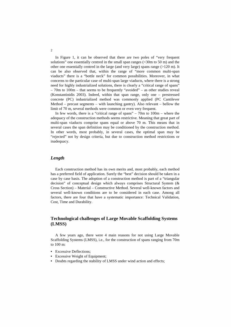
In Figure 1, it can be observed that there are two poles of “very frequent solutions” one essentially centred in the small span ranges (<30m to 50 m) and the other one essentially centred in the large (and very large) spans range (>120 m). It can be also observed that, within the range of “more common multi-span viaducts” there is a “bottle neck” for common possibilities. Moreover, in what concerns to the particular case of multi-span large viaducts, where there is a strong need for highly industrialized solutions, there is clearly a “critical range of spans” – 70m to 100m – that seems to be frequently “avoided” – as other studies reveal (Konstantinidis 2003). Indeed, within that span range, only one – prestressed concrete (PC) industrialized method was commonly applied (PC Cantilever Method – precast segments – with launching gantry). Also relevant – bellow the limit of 70 m, several methods were common or even very frequent.
In few words, there is a “critical range of spans” – 70m to 100m – where the adequacy of the construction methods seems restrictive. Meaning that great part of multi-span viaducts comprise spans equal or above 70 m. This means that in several cases the span definition may be conditioned by the construction method. In other words, most probably, in several cases, the optimal span may be “rejected” not by design criteria, but due to construction method restrictions or inadequacy.
Length
Each construction method has its own merits and, most probably, each method has a preferred field of application. Surely the “best” decision should be taken in a case by case basis. The adoption of a construction method is part of a “triangular decision” of conceptual design which always comprises Structural System (& Cross Section) – Material – Constructive Method. Several well-known factors and several well-known conditions are to be considered in each case. Among all factors, there are four that have a systematic importance: Technical Validation, Cost, Time and Durability.
Technological challenges of Large Movable Scaffolding Systems (LMSS)
A few years ago, there were 4 main reasons for not using Large Movable Scaffolding Systems (LMSS), i.e., for the construction of spans ranging from 70m to 100 m:
• Excessive Deflections; • Excessive Weight of Equipment; • Doubts regarding the stability of LMSS under wind action and effects;
3
• Productivity and Construction Time.
Other possible reasons could also be pointed out, such as logistic restrictions, concrete pouring control (due to duration and volume), or off-shore restrictions, but surely reasonable solutions to overcome them could be developed, if the formers were overcome.
Excessive deflections
The deflection of a MSS under fresh concrete load is one of its main operational characteristics. Recently, the larger span MSS (60 to 70m span) were often characterized by mid-span deflections (during concrete pouring operation) which were near the limits of acceptable operational values.
Indeed, the common values of mid-span deflections (D) during concrete pouring operation, for most common MSS were within the range L/1000<D<L/400. That would represent absolute values within the interval 70mm<D<250mm for the span range 70m<L<100 m (Vasques de Carvalho 2008; Pacheco et al. 2011).
Even applying pre-cambers, the potential geometric deviations could be easily greater than common acceptable tolerances.
Additionally, this level of deformation could induce structural problems on the erected decks - such as cracks - in the event of long concrete pouring operations and/or if more than one stage of concrete operations occurs, in which the concrete of first stages partially withstands the load from the subsequent stages (Pacheco et al.).
According to previous studies, for LMSS, good results are achieved if the mid-span deflection during concrete pouring is limited to L/1000 (Pacheco et al. 2011).
Excessive weight
The MSS weight may have impact on the deck design and also on the piers design.
It is known that the design of the deck may significantly depend on the constructive joint location (usually between at L/4 or L/5 from the pier). Associated with this issue it is also relevant the location of MSS back support (typically on the deck cantilever).
In what concerns to piers design, any approximation, even simplified, would be much difficult to achieve. Indeed, the piers height, the structural design, the specific actions of the local, etc., could have important influence in each case. Nevertheless, if conventional MSS were applied for 70m to 100m spans, Bridge Designers should expect service horizontal forces values on the top of the piers

4
that could easily reach values from 75 ton to 150 ton. Regarding this matter, the MSS sliding devices specification is also an important issue (Pacheco et al. 2011).
Stability of LMSS under wind effect
The study of wind action and wind effects in MSS involves some particularities where importance is enhanced with the span increase.
Design wind loads are usually substantially different in launching operation stages and in equipment stationary stages. This is essentially justified by the duration of the stages/operations and MSS Operational Manuals restrictions (Resende et al. 2015).
The wind actions for this type of equipment are not specifically included in known codes.
It is then necessary to define specific rules and criteria for this type of structures, with, as explained before, very particular characteristics. Nevertheless, in the particular case of MSS, there is specific and useful bibliography that deals with the disparity between MSS operational stages, using different wind velocities for each situation (SEOPAN 2007).
Previous studies (Rosignoli 2013, Pacheco et al. 2015) show that natural frequencies of MSS during launching stage, as expectable, decrease with the span increase. Although such operation is to be conditioned by actual wind speed measured during the operation, if natural frequencies are too low, there is not an adequate domain of involved phenomena. This fact induces doubts on the applicability of previous knowledge to the study of stability of LMSS under wind effect.
Indeed, LMSS natural frequencies are below the former typical values for MSS (Pacheco et al. 2011), additional research is strongly recommended, as dynamic phenomena may occur.
Construction time and productivity of MSS technology for large spans
The last point identified as demanding further technological development is productivity. As a matter of fact, productivity is obviously a key issue for all intervenient in a Bridge Project but, particularly important for the constructors.
In the beginning of the XXI century there is plethora of experiences referring to cruise MSS deck erection productivities nearby the value 3 km/year, for the span range of 40m to 60 m.
But, according to known relates, that value could decrease down to 2 km/year (or lower values) of cruise deck erection for 70m span decks and the expectative for larger spans is not better. For the decision makers, values of productivity

5
around 2km/year are not compatible with the industrialized needs of multi-span viaducts, which could be near from 4 km/year achieved with other methods.
The Organic Prestressing (OPS) technology – brief description
The present chapter, which appears to be disconnected from the previous, gives a brief and overall overview of Organic Prestressing System (OPS) to all readers not yet familiarized with this technology.
OPS is an automatically adaptive prestressing system which has the ability to increase or decrease prestressing forces according to load variation. It was first developed using as an inspiration the behaviour of nature formed structures (biomimetics), more specifically the muscle behaviour. One can describe it as a prestressing system in which the tension applied to cables is automatically adjusted to the actuating loads, through a control system, in order to reduce the structural deformations and minimize tensions (Pacheco et al. 2007).
Using MSS as an explanatory reference, the OPS main elements are 1) the actuator and the active anchorage, 2) the unbonded cables, 3) the sensors, 4) the electronic controller in the girder control unit, 5) passive anchorage and 6) deviation shores (please see Figure 2).
Figure 2 - OPS Main Elements and layout

6
The OPS control is ruled by an algorithm that adopts the girder mid span deflection as main control variable. Mid span deflection is monitored by pressure transducers (sensors) continuously transmitting signals to the control unit (PLC).
The control algorithm computes actuation decisions (hydraulic cylinders stroke variations) which consequently affects tension on prestressing cables. Actuation decision is based on mid span deflection changing tendency, filtering instantaneous deflection noise due to vibration.
To ensure an adequate reliability level, OPS is provided with distinctive and redundant sensors with measures that are permanently compared to guarantee that the algorithm decision is always based on accurate information.
Overcoming LMSS technological challenges – OPS impact
In Chapter 2, technological challenges to enable the use of Large Movable Scaffolding Systems were identified. In the present Chapter, potential solutions to overcome such challenges are described.
Overcoming excessive deflections
As mentioned before, OPS is nothing more than an active control prestressing system, whose objective is to reduce deformations and/or stresses due to live loading.
In the practical case of the Overhead LMSS used for Rio Cabriel Bridge (Spain) construction, the maximum mid-span deflection (neglecting vibrations) is about 25 mm. As the span of the bridge is 70 m, that give us an approximate mid span deflection of L/3000.
In the particular case of underslung MSS strengthened with OPS technology, as described in previous publications (Pacheco et al. 2014) that value may be reduced to L/10.000 or even less.
In all MSS and LMSS applications with OPS technology, maximum mid-span deflections observed are always about L/2000 and in some cases much less (Pacheco et al. 2011). Meaning that the technological needs for mid span deflections bellow L/1000 is clearly overcome.
Overcoming excessive weight
The static effect of organic prestressing is nothing different from the static effect of conventional prestressing. Meaning that, when OPS is applied, a very important compensation of MSS Main Girders flexural moments is achieved. And,

7
if stresses are reduced, the main girder profiles are reduced, subsequently the weight of the equipment decreases.
Several studies published before (Pacheco et al.) allow concluding that for
conventional MSS span ranges (until 70m span) that weight reduction may be above 30%. The relative difference increases with the span length.
For large spans (70m to 100 m) that comparison is not feasible since conventional MSS for multi-span bridges with spans larger than 72m are not known by the authors.
Let us consider Figure 3, where the registration of the weight of 23 different conventional MSS is pointed and where a linear approximation of MSS conventional weight is drawn. A very simplified analysis, which equalize the deck flexural moment over the last pier with deck, for the maximum constructive loading scenario and for bridge service loading (the same pier with the complete deck), allow to obtain grossly approximate values of what would be approximately a neutral weight for the deck design (Pacheco et al. 2011). A simplified indicative linear projection of “MSS neutral Weight” may then be drawn.
In Figure 3, it is then possible to observe that above approximately 65m of span, the weight of conventional MSS tends to be conditioning for the deck design, and that tendency clearly increases with the span length. In the same picture, a simplified projection of “LMSS weight (with OPS)” is also drawn. It is possible to observe that the point of interception between the “MSS Neutral weight” and the “LMSS weight (with OPS)” lines is clearly above the former 65m and approximately near from 90 m.
Presently there is an application of a LMSS with OPS for 90m span – see
Figure 4. This equipment traveling mass weight is about 1250 ton (with a
Figure 3 - MSS weight (with and without OPS)/ Span relation – versus – MSS neutral weight

8
maximum expected variation of 5%), which reasonably accomplishes predicted “LMSS (with OPS)” line.
Wind effect assessment
To overcome any doubts on wind effect assessment on LMSS, additional research is being developed following previous preliminary studies on critical issues related to wind action on LMSS. It is also important to understand that the wind effects on LMSS – either the static, and/or dynamic – are to be evaluated in a probabilistic basis, as the wind forces and their effects on the LMSS structure cannot be formulated on definite mathematical functions of time (Andre et al. 2015; Pacheco et al.2011).
As a first approach, a robust methodology to overcome this issue should generally comprise the following integrated measures:
– Previous studies on local (near the site) wind actions – site registry of the previous months and long-term data obtained from the nearest station;
– Judicious choice of the design wind velocities by the LMSS designer in order to obtain sufficiently small probabilities of occurrence, ensuring a safe operation of the LMSS (Resende et al. 2015) and without causing excessive operational restrictions;
Figure 4 - LMSS for 90m spans – 3D Model (currently under production)

9
– Adoption of adequate measures during the conceptual design of the LMSS in order to ensure adequate natural frequencies, in particular in maximum cantilever configuration during launching operation (Pacheco et al. 2015);
– Progressive development of the Operations Manual (by versions), more conservative in first launching operations and upgraded afterwards - with increased operational wind speed limits;
– Continuous monitoring of wind action is to be always applied (already common);
– In first the first applications of each LMSS, monitoring of structural response is highly recommended.
Wind effect assessment
Recent works regarding productivity on span by span, cast in situ, and segmental precast emerging technologies have been recently published, comprising possible peak productivities of 3 km to 4 km/year per deck/equipment unit (Pacheco et al. 2014).
In span by span cast in place solutions, the decks erection may begin in a much earlier stage of construction, thus, even if the “Deck Construction” task is actually longer, the total construction period may be shorter than in precast solutions.
Under certain circumstances, both cast in situ and precast segmental, span by span, construction methods, may achieve similar levels of productivity, or even in some cases higher than other fast construction methods. Surely, this should be analyzed in a case by case basis, but the productivity of mentioned span by span methods is not an obstacle anymore for implementation of LMSS technology.
CONCLUSIONS
Most probably, OPS technology is still at an early stage of its development, but so far it has already brought new limits to some of the most common methods for multi-span large decks (see Figure 5). In particular, it is now possible to increase in situ, span by span methods span range up to 100m span. The first application for 90m span is already ongoing (under production). Several other projects (still in design stage) are already being developed worldwide within this new span range limits.
Certainly, there are now less restrictions for decisions makers, and most probably, in certain cases, this span range increase will contribute for the adoption of the most rational and competitive solution.

10
Mainly, this represents another degree of freedom for bridge designers, for
constructors and for project owners.
References
1. Konstantinidis, D. and Maravas, A. (2003) Egnatia Motorway concrete bridges statistics, Proceedings of the 31st ASECAP Study, Portoroz, Slovenia, May 18–21: 92–109. 2. Pacheco, P., Coelho, H., Borges, P., Guerra, A. (2011) Technical Challenges of Large Movable Scaffolding Systems, Structural Engineering International (IABSE), Vol. 21, Number. 4: 450–455. 3. Pacheco, P., Guerra, A., Borges, P., Coelho, H. (2007) A scaffolding system strengthened with organic prestressing – the first of a new generation of structures, in Structural Engineering International, journal of the International Association for Bridge and Structural Engineering, Vol. 17, Number 4, November 2007: 314-321(8). 4. Pacheco, P., Coelho, H., Resende, A. and Soares I (2014) High productivity in bridge construction – the OPS effect. 9th International Conference on Short and Medium Span Bridges, Calgary, Alberta, Canada. 5. Resende, A., Coelho, H. and Pacheco, P. (2015) Preliminary Assessment of Wind Actions in large span MSS, Porto, Proceedings of Multi-span Large Bridges 2015 International Conference, CRC Press. 6. Rosignoli, Marco, 2013, Bridge Construction Equipment, Thomas Telford. 7. SEOPAN, Confederación de la Construcion (2007), Manual of Self launching scaffoldings, in spanish, 1a ed., CNC, Madrid. 8. Vasques de Carvalho, D. (2008) Study of the application of the prestressing application stage in decks constructed span by span – deformation of the scaffoldings effects, in Portuguese, MSc Thesis, FEUP.
Figure 5 - Actual span ranges for the most common constructive methods/bridge types: the OPS impact