orewFord - soberit.hut.fi · orewFord Software is becoming more pervasive and traditionally...
107
Transcript of orewFord - soberit.hut.fi · orewFord Software is becoming more pervasive and traditionally...

Foreword
Software is becoming more pervasive and traditionally non-software productsare increasingly turning into software-intensive products. Furthermore, the of-fering of many companies is moving towards service-oriented business insteadof software or software-intensive products. At the same time, the amount ofvariability required is constantly increasing in order to improve customer sat-isfaction, cover larger and more heterogeneous markets, and so on. As moreand more products and services must support variability, e�cient variabilitymanagement may become essential for surviving in competitive markets
Variability management is facing new challenges on its own and at least threetrends can be identi�ed. Firstly, binding of variability, i.e., the selection of theright variant is delayed later in the product's life cycle. Variability can also bere-bound, i.e., the product is recon�gured, and this can take place at runtime.Secondly, variability also concerns the quality attributes or non-functional prop-erties of products. Product variants may even be di�erentiated solely in termsof their quality attributes. Thirdly, all variation possibilities cannot be assumedto be known beforehand, as, for example, new software or service componentsare developed by third parties and need to be incorporated into the product.Furthermore, products also need to adapt to the context of use. These trendsare not separable but take place concurrently, which makes the preparation forthem even more challenging.
In order to face the future challenges of variability management, clear con-ceptual foundation, rigorous modelling methods and languages, and di�erentkinds of tools are needed to describe and manage the variability and to imple-ment e�ective means for deriving products and services. The goal of this work-shop is to explore and explicate the current status and ongoing work within the�eld of variability management by bringing together researchers and practition-ers from di�erent disciplines and application domains, and on this basis supportfruitful transfer of knowledge.
The workshop received eleven submission of, which nine were accepted tothe workshop. Five of the papers were accepted as full papers and four as shortpapers. The topics of the contributions focus on a set of common themes, suchas modelling methods and tools and future directions in software variabilitymanagement. Together the contributions form a basis for fruitful discussions onthe emerging body of knowledge. We expect the workshop to make a relevantcontribution in this respect by bringing together researchers with di�erent back-grounds and linking the research e�orts with industrial experiences and needsfrom di�erent domains.
April, 2007
Tomi Männistö, Eila Niemelä and Mikko Raatikainen

Organizers
Workshop Chairs
Tomi Männistö, Helsinki University of Technology (TKK), Software Businessand Engineering institute (SoberIT), Finland
Eila Niemelä, VTT Technical Research Centre of Finland, Finland
Mikko Raatikainen (local arrangement), Helsinki University of Technology (TKK),Software Business and Engineering institute (SoberIT), Finland
Program Committee
Jan Bosch, Nokia, FinlandKrzysztof Czarnecki, University of Waterloo, CanadaAlexander Felfernig, University of Klagenfurt, AustriaAlbert Haag, SAP, GermanyPeter Knauber, Mannheim University of Applied Sciences, GermanyKai Koskimies, Tampere University of Technology, FinlandRene Krikhaar, ICT NoviQ, NetherlandsThorsten Krebs, University of Hamburg, GermanyCharles Krueger, BigLever Software, USA.Johan Lilius, Åbo Akademi University, FinlandJohn MacGregor, Robert Bosch GmbH, GermanyMari Matinlassi, VTT, Finlandllkka Niemelä, Helsinki University of Technology, FinlandKlaus Pohl, Lero, Ireland, University of Duisburg-Essen, GermanyChristian Prehofer, Nokia, FinlandPierre-Yves Schobbens, University of Namur, BelgiumJuha-Pekka Tolvanen, MetaCase, FinlandRob van Ommering, Philips Research, Netherlands

Contents
Full PapersTowards the Comparative Evaluation of Feature Diagram LanguagesPatrick Heymans, Pierre-Yves Schobbens, Jean-Christophe Trigaux, Raimundas Matulevičius, Andreas Classen, Yves Bontemps . . . . . . . . . . . . . . . . . . . . . . . . . . . . . . . . . . . . . . . . . . . . . . 1
Ontology-Based Software Reliability Evaluation and Software Reliability OntologyJiehan Zhou, Eila Niemelä, Antti Evesti . . . . . . . . . . . . . . . . . . . . . . . . . . . . . . . . . . . . . . . 17
An Analysis of Variability Modeling and Management Tools for Product Line Devel-opmentRafael Capilla, Alejandro Sánchez, Juan C. Dueñas . . . . . . . . . . . . . . . . . . . . . . . . . . . . . . . 32
Tool-Supported Multi-Level Language EvolutionMarkus Pizka, Elmar Jürgens . . . . . . . . . . . . . . . . . . . . . . . . . . . . . . . . . . . . . . . . . . . . . . . 48
Kumbang Modeler: A Prototype Tool for Modeling VariabilityHanna Koivu, Mikko Raatikainen, Marko Nieminen, Tomi Männistö . . . . . . . . . . . . . . . . . 68
Short PapersVariability Management and Compositional SPL DevelopmentJilles van Gurp . . . . . . . . . . . . . . . . . . . . . . . . . . . . . . . . . . . . . . . . . . . . . . . . . . . . . . . . . . 81
Variations in Model-Based Composition of DomainsAnca Daniela Ionita, Jacky Estublier, German Vega . . . . . . . . . . . . . . . . . . . . . . . . . . . . . . . . 87
Towards Integration of Modelling and Reusing Software CasesKatharina Wolter, Lothar Hotz, Thorsten Krebs . . . . . . . . . . . . . . . . . . . . . . . . . . . . . . . . . . . 93
Goal and Variability Modeling for Service-oriented System: Integrating i* with Deci-sion ModelsPaul Grünbacher, Deepak Dhungana, Norbert Seyff, Michael Quintus, Roger Clotet, Xavier Franch, Lidia López, Jordi Marco . . . . . . . . . . . . . . . . . . . . . . . . . . . . . . . . . . . . . . . . . . . . . 99
Towards the Comparative Evaluation of FeatureDiagram Languages
Patrick Heymans, Pierre-Yves Schobbens, Jean-Christophe Trigaux?,Raimundas Matulevicius, Andreas Classen and Yves Bontemps
PReCISE research centre, Computer Science Faculty, University of Namur21, rue Grandgagnage – B-5000, Namur (Belgium)
{phe,pys,jtr,rma,aclassen,ybo}@info.fundp.ac.be
Abstract. This paper proposes a path to defragmenting research on feature dia-gram languages: (1) a global quality framework to serve as a language quality im-provement roadmap; (2) a set of formally defined criteria to assess the semantics-related qualities of feature diagram languages; (3) a systematic method to for-malise these languages and make them ready for comparison and efficient toolautomation. The novelty of this paper resides in the latter point and the integra-tion. The results obtained so far are summed up and future works are identified.
1 Introduction
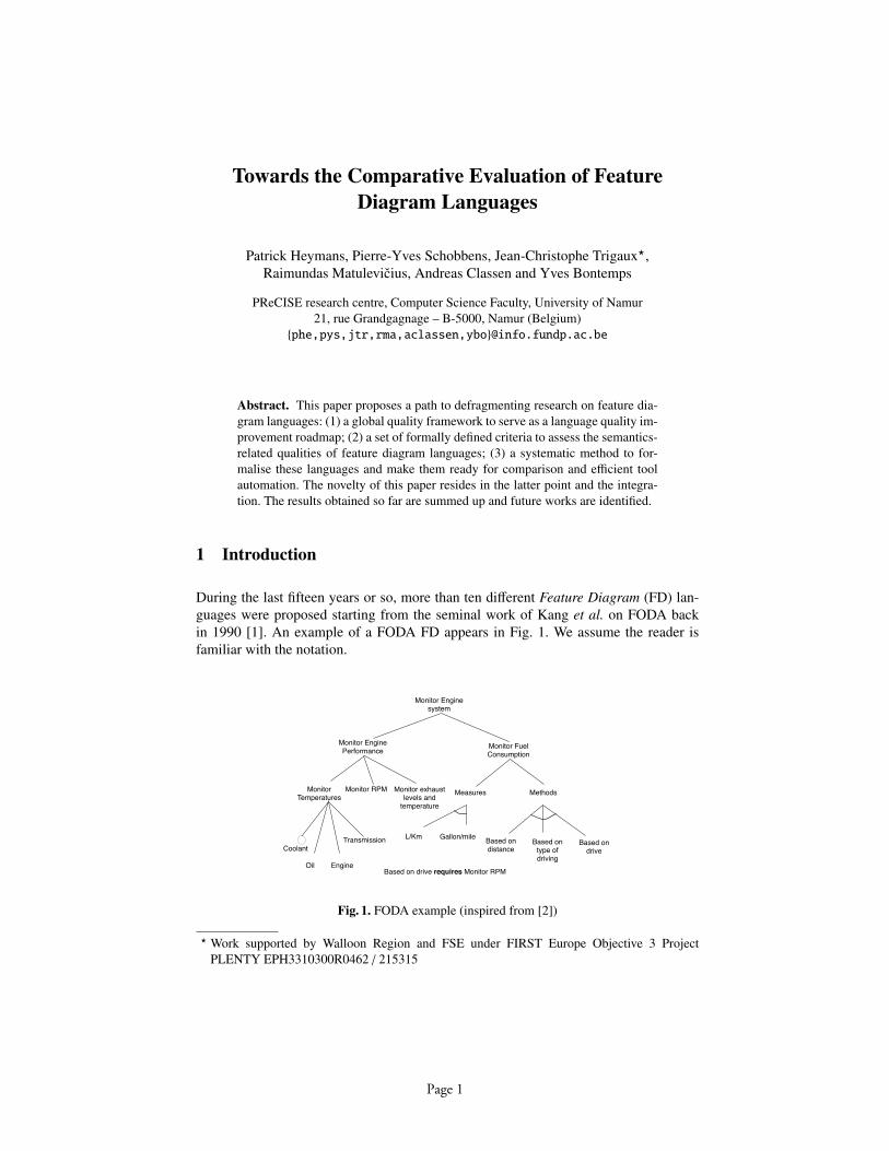
During the last fifteen years or so, more than ten different Feature Diagram (FD) lan-guages were proposed starting from the seminal work of Kang et al. on FODA backin 1990 [1]. An example of a FODA FD appears in Fig. 1. We assume the reader isfamiliar with the notation.
Monitor Temperatures
Coolant
Oil
Monitor Engine system
Monitor Fuel Consumption
Monitor Engine Performance
Engine
Transmission
Monitor exhaust levels and
temperature
Monitor RPM
Based on type of driving
Gallon/mileL/Km
Measures
Based on drive
Based on distance
Methods
Based on drive requires Monitor RPM
Fig. 1. FODA example (inspired from [2])
? Work supported by Walloon Region and FSE under FIRST Europe Objective 3 ProjectPLENTY EPH3310300R0462 / 215315
Page 1

Since Kang et al.’s proposal, several extensions to FODA were devised [3–9] (seealso Table 1). When looking at these FD languages, one immediately sees aesthetic dif-ferences (see, e.g., Fig.2). Although concrete syntax is an important issue in its ownright [10], this work focusses on what is really behind the pictures: semantics. Wenoticed that proponents of FD languages often claimed for added value of their lan-guage in terms of precision, unambiguity or expressiveness. Nevertheless, our previouswork [11–15] demonstrated that the terminology and evaluation criteria that they usedto justify these claims were often vague, and sometimes even misleading. We also triedto give a precise meaning to the constructs of those languages.
OFT,OFD,GPFT RFD VBFD EFD PFT
1..1
s s
Fig. 2. Concrete syntaxes for xor-decomposition
Although we note that recent research has devoted more attention to the semanticfoundations of these languages [16–22], we still lack concrete means to discriminatebetween these proposals.
This paper suggests a method to evaluate and compare FD languages focused onthe study of their semantics. This method relies on formally defined criteria and ter-minology, based on the highest standards in formal language definition [23]. It is alsosituated with respect to SEQUAL [24, 25], a comprehensive framework for assessingand improving the quality of modelling languages.
In Section 2, we briefly present SEQUAL. Section 3 recalls good language defi-nition principles from [23]. On these grounds, Section 4 continues with the definitionof the criteria that our method aims to investigate: expressiveness, embeddability (alsocalled naturalness), succinctness and (computational) complexity. The method is de-scribed in Section 5 and constitutes the main contribution of this paper. Section 6 sum-marises the results obtained so far [13–15]. The paper finishes by discussing the currentlimitations of the method and the remaining research challenges (Section 7), before itconcludes (Section 8). This paper is short version of a technical report [26]1.
2 Quality of Models and Languages
Assessing and improving the quality of modelling is a complex and multidimensionaltask. A comprehensive view of the concerns involved is given in the SEQUAL (semiotic
1 Available at http://www.info.fundp.ac.be/∼phe/docs/papers/TechRep Eval FPof FDL 06.pdf
Page 2
quality) framework, developed over the last decade by Krogstie et al. [25]. SEQUALis based on a distinction between semiotic levels: syntactic, semantic and pragmatic.It adheres to a constructivistic world-view that recognises model creation as part of adialog between participants whose knowledge changes as the process takes place.
SEQUAL is amenable to specific criteria and guidelines by tailoring. Its main ad-vantages are that (1) it helps situate one’s investigations within a comprehensive qualityspace, (2) it acts as a checklist of qualities to be pursued and (3) it recommends generalguidelines on how to proceed.
Our investigation is targeted semantic and pragmatic qualities of FDs which wehave found to be somehow neglected in the current state of the art. So doing, we willsee that we inevitably interfere with the other qualities, mainly syntactic quality.
The problem we encounter is that representative objects of study – models – donot always exist, or at least are not easily available. And this is indeed the case forFDs which (1) are an emerging modelling paradigm, and (2) have the purpose of repre-senting highly strategic company information. Since representative models2 are almostnowhere to find, we concentrate on improving the quality of FD languages.
Domain appropriateness
Language externalizability appropriateness Participant language knowledge appropriateness
Organisational appropriateness
Comprehensibility appropriateness
Technical actor interpretation appropriateness
Goals of modelling
G
Modelling domain
D
Participant knowledge
K
Language extension
L
Social actor interpretation
I
Technical actor interpretation
T
Model externalisation
M
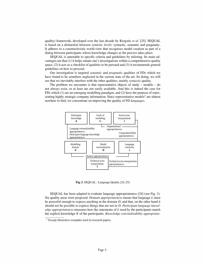
Fig. 3. SEQUAL : Language Quality [24, 25]
SEQUAL has been adapted to evaluate language appropriateness [24] (see Fig. 3).Six quality areas were proposed. Domain appropriateness means that language L mustbe powerful enough to express anything in the domain D, and that, on the other hand itshould not be possible to express things that are not in D. Participant language knowl-edge appropriateness measures how the statements of L used by the participants matchthe explicit knowledge K of the participants. Knowledge externalisability appropriate-
2 Except illustrative examples used in research papers.
Page 3

ness means that there are no statements in K that cannot be expressed in L. Comprehen-sibility appropriateness means that language users understand all possible statements ofL. Technical actor interpretation appropriateness defines the degree to which the lan-guage lends itself to automatic reasoning and supports analysability and executability.Finally, organisational appropriateness relates L to standards and other needs withinthe organisational context of modelling.
Not being able to assess model qualities directly, our investigations were re-targetedat three main language qualities: domain appropriateness, comprehensibility appropri-ateness and technical actor interpretation appropriateness. The matching of the inves-tigated criteria wrt these qualities is further discussed in Section 7. In the next section,we will first introduce the basic notions behind these criteria (Section 3), and then thecriteria themselves (Section 4).
3 Formal definition of visual languages
In [23], Harel and Rumpe recognise that: “Much confusion surrounds the proper defi-nition of complex modelling languages [. . . ]. At the root of the problem is insufficientregard for the crucial distinction between syntax and true semantics and a failure toadhere to the nature and the purpose of each.” [23] Although they are far less complexthan, e.g., the UML3, we demonstrated in previous papers [11–14] that FDs were also“victims” of similar “mistreatments”.
Harel and Rumpe make it clear that the unambiguous definition of any modellinglanguage must consist of three equally necessary elements: a syntactic domain (L), asemantic domain (S) and a semantic function (M) (see Fig. 4). All three should bedefined through explicit, rigid and unambiguous rules, hence the use of mathematics.
Syntactic domain (L) Semantic domain (S)
All the diagrams
one can write in LAll the possible meanings
of L diagrams
Semantic function(M: L ! S)myDiagram
yourDiagram
herDiagram
M(yourDiagram)
M(myDiagram)
M(herDiagram)
= M(hisDiagram)hisDiagram
Fig. 4. The 3 constituents of a formal language
During our survey, we could observe that many FD languages were never formallydefined. Maybe, some answers to why this is so are given in [23] where the authors point
3 In [23], one of Harel and Rumpe’s main motivations is to suggest how to improve the UML.
Page 4
out of set of frequent misconceptions about formal semantics, e.g., “Semantics is themetamodel”, “Semantics is dealing with behaviour”, “Semantics is being executable”,“Semantics means looking mathematical”, etc. This folklore is demystified [23]. Fornow, we turn to the definitions of L, S andM.
3.1 Syntax
Concrete syntax is the physical representation of the data (on screen, or on paper) interms of lines, arrows, closed curves, boxes and composition mechanisms involvingconnectivity, partitioning and “insideness” [23].
Although discouraged by best pratice, most of the (informal) definitions of the se-mantics of FDs we found in the literature were based on concrete syntax, usually dis-cussed on FD examples. Most of the time, a substantial part of the semantics was im-plicit, leaving it to the diagrams to “speak for themselves”.
The abstract syntax (L) is a representation of data that is independent of its physicalrepresentation and of the machine-internal structures and encodings. It thus makes thesyntactic rules simpler and more portable. The set of all data that comply with a givenabstract syntax is called the syntactic domain.
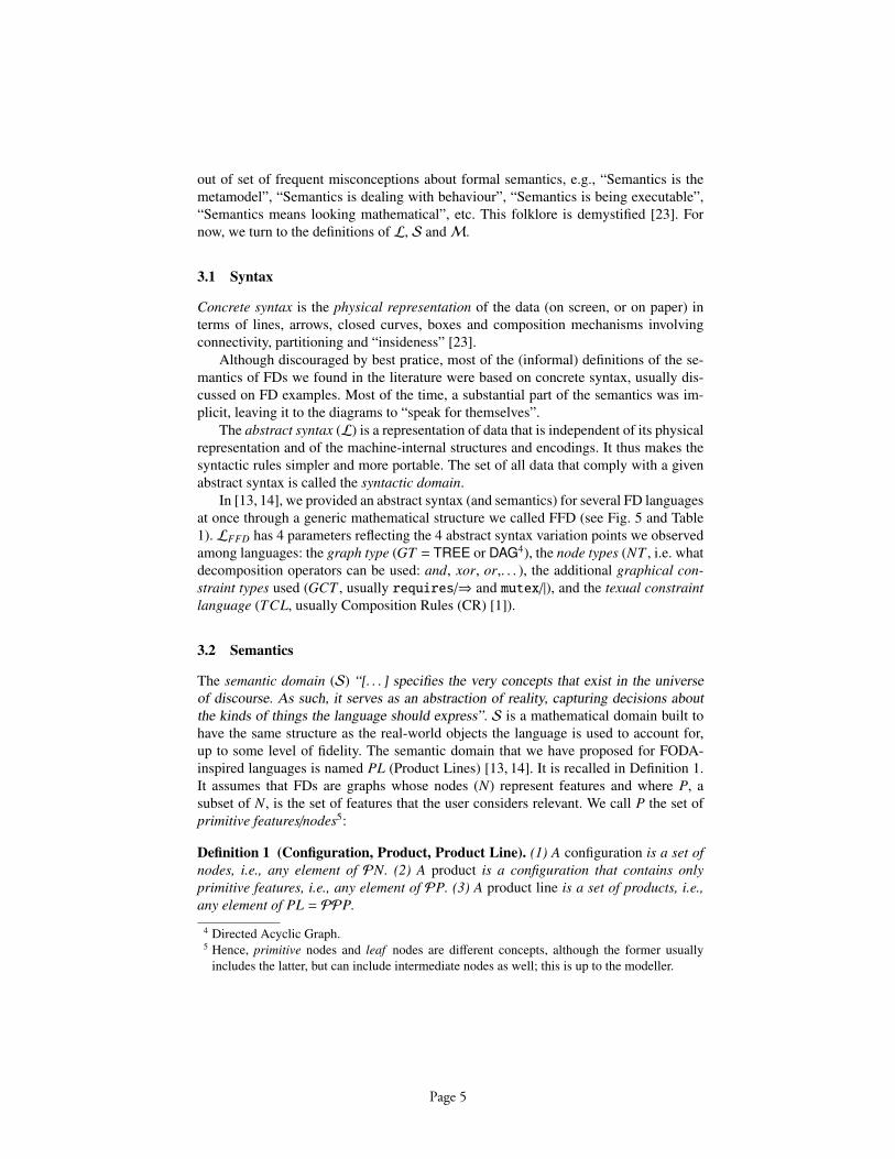
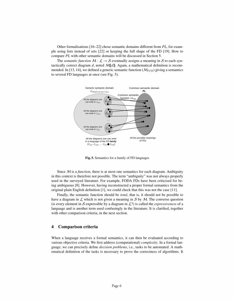
In [13, 14], we provided an abstract syntax (and semantics) for several FD languagesat once through a generic mathematical structure we called FFD (see Fig. 5 and Table1). LFFD has 4 parameters reflecting the 4 abstract syntax variation points we observedamong languages: the graph type (GT = TREE or DAG4), the node types (NT , i.e. whatdecomposition operators can be used: and, xor, or,. . . ), the additional graphical con-straint types used (GCT , usually requires/⇒ and mutex/|), and the texual constraintlanguage (TCL, usually Composition Rules (CR) [1]).
3.2 Semantics
The semantic domain (S) “[. . . ] specifies the very concepts that exist in the universeof discourse. As such, it serves as an abstraction of reality, capturing decisions aboutthe kinds of things the language should express”. S is a mathematical domain built tohave the same structure as the real-world objects the language is used to account for,up to some level of fidelity. The semantic domain that we have proposed for FODA-inspired languages is named PL (Product Lines) [13, 14]. It is recalled in Definition 1.It assumes that FDs are graphs whose nodes (N) represent features and where P, asubset of N, is the set of features that the user considers relevant. We call P the set ofprimitive features/nodes5:
Definition 1 (Configuration, Product, Product Line). (1) A configuration is a set ofnodes, i.e., any element of PN. (2) A product is a configuration that contains onlyprimitive features, i.e., any element of PP. (3) A product line is a set of products, i.e.,any element of PL = PPP.
4 Directed Acyclic Graph.5 Hence, primitive nodes and leaf nodes are different concepts, although the former usually
includes the latter, but can include intermediate nodes as well; this is up to the modeller.
Page 5
Other formalisations [16–22] chose semantic domains different from PL, for exam-ple using lists instead of sets [22] or keeping the full shape of the FD [19]. How tocompare PL with other semantic domains will be discussed in Section 5.
The semantic functionM : L → S eventually assigns a meaning in S to each syn-tactically correct diagram d, notedM[[d]]. Again, a mathematical definition is recom-mended. In [13, 14], we defined a generic semantic function (MFFD) giving a semanticsto several FD languages at once (see Fig. 5).
LOFT
LOFD
LPFT
...
Generic syntactic domain
LFFD(GT,NT,GCT,TCL)
All the diagrams one can write
in a language of the FD family
(LOFT
, LOFD
, ... , LPFT ! LFFD)
All the diagrams one
can write in LOFT
All the diagrams one
can write in LOFD
All the diagrams one
can write in LPFT
Common semantic domain
PL
All the possible meanings
of FDs
Common semantic
function MFFD
Fig. 5. Semantics for a family of FD languages
SinceM is a function, there is at most one semantics for each diagram. Ambiguityin this context is therefore not possible. The term “ambiguity” was not always properlyused in the surveyed literature. For example, FODA FDs have been criticised for be-ing ambiguous [8]. However, having reconstructed a proper formal semantics from theoriginal plain English definition [1], we could check that this was not the case [11].
Finally, the semantic function should be total, that is, it should not be possible tohave a diagram in L which is not given a meaning in S byM. The converse question(is every element in S expressible by a diagram in L?) is called the expressiveness of alanguage and is another term used confusingly in the literature. It is clarified, togetherwith other comparison criteria, in the next section.
4 Comparison criteria
When a language receives a formal semantics, it can then be evaluated according tovarious objective criteria. We first address (computational) complexity. In a formal lan-guage, we can precisely define decision problems, i.e., tasks to be automated. A math-ematical definition of the tasks is necessary to prove the correctness of algorithms. It
Page 6
also allows to study complexity, thereby assessing their scalability. Results give an in-dication about the worst case, and how to handle it. Heuristics taking into account themost usual cases can be added to the backbone algorithm, to obtain practical efficiency.
In [13], we studied the complexity of a selection of FD-related decision problems:(1) satisfiability: given a diagram d, is M[[d]] = ∅ true? (2) equivalence: given twodiagrams d1 and d2, is M[[d1]] = M[[d2]] true? (3) model-checking (called product-checking for FDs): given a product c and a diagram d, is c ∈ M[[d]] true? (4) inter-section: compute a new diagram d3 such thatM[[d3]] = M[[d1]]
⋂M[[d2]]. (5) union:
compute a new diagram d3 such thatM[[d3]] =M[[d1]]⋃M[[d2]]. (6) reduced product:
compute a new diagram d3 such thatM[[d3]] = {c1 ∪ c2|c1 ∈ M[[d1]], c2 ∈ M[[d2]]}.When languages, in addition to having a formal semantics, also share a common
semantic domain (S), we can compare them with additional criteria. We use three com-mon criteria:
– expressiveness: what can the language express?– embeddability (or macro-eliminability): when translating a diagram to another lan-
guage, can we keep its structure?– succinctness: how big are the expressions of a same semantic object?
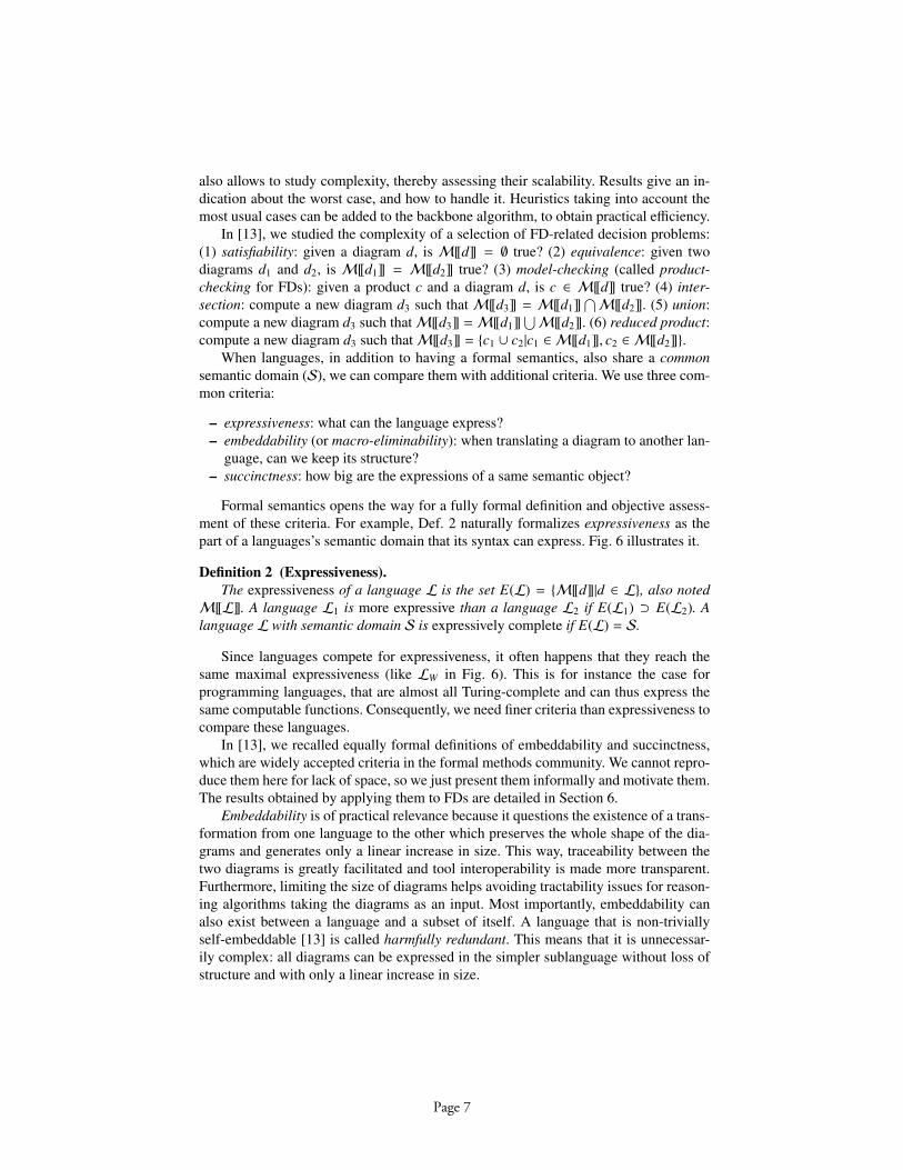
Formal semantics opens the way for a fully formal definition and objective assess-ment of these criteria. For example, Def. 2 naturally formalizes expressiveness as thepart of a languages’s semantic domain that its syntax can express. Fig. 6 illustrates it.
Definition 2 (Expressiveness).The expressiveness of a language L is the set E(L) = {M[[d]]|d ∈ L}, also noted
M[[L]]. A language L1 is more expressive than a language L2 if E(L1) ⊃ E(L2). Alanguage L with semantic domain S is expressively complete if E(L) = S.
Since languages compete for expressiveness, it often happens that they reach thesame maximal expressiveness (like LW in Fig. 6). This is for instance the case forprogramming languages, that are almost all Turing-complete and can thus express thesame computable functions. Consequently, we need finer criteria than expressiveness tocompare these languages.
In [13], we recalled equally formal definitions of embeddability and succinctness,which are widely accepted criteria in the formal methods community. We cannot repro-duce them here for lack of space, so we just present them informally and motivate them.The results obtained by applying them to FDs are detailed in Section 6.
Embeddability is of practical relevance because it questions the existence of a trans-formation from one language to the other which preserves the whole shape of the dia-grams and generates only a linear increase in size. This way, traceability between thetwo diagrams is greatly facilitated and tool interoperability is made more transparent.Furthermore, limiting the size of diagrams helps avoiding tractability issues for reason-ing algorithms taking the diagrams as an input. Most importantly, embeddability canalso exist between a language and a subset of itself. A language that is non-triviallyself-embeddable [13] is called harmfully redundant. This means that it is unnecessar-ily complex: all diagrams can be expressed in the simpler sublanguage without loss ofstructure and with only a linear increase in size.
Page 7
In case linear translations are not possible, the blow-up in the size of the diagrammust be measured by succinctness. If L1 is more succinct than L2, this usually entailsthat L1’s diagrams are likely to be more readable. Also, if one needs to translate fromL1 to L2
6, succinctness will be an indicator of the difficulty to maintain traceabilitybetween the orginal and the generated diagram. Traceability of linear translations isusually easier but is likely to become more difficult as the size of the generated diagramsgrows bigger. However, this should not be concluded too hastily since succinctnessdoes not provide information on the structure of the generated diagrams7. In this sense,succinctness is a coarser-grained criteria than embeddability.
...
Syntactic domains Semantic domain
Semantic functions
E(LW)=S
E(LY)
E(LZ)
E(LX)
LW
LYLX
LZ
My!Ly"
Mz!Lz"
Mx!Lx"
Mw!Lw"
Fig. 6. Comparing expressiveness
5 A Comparison Method for FD languages
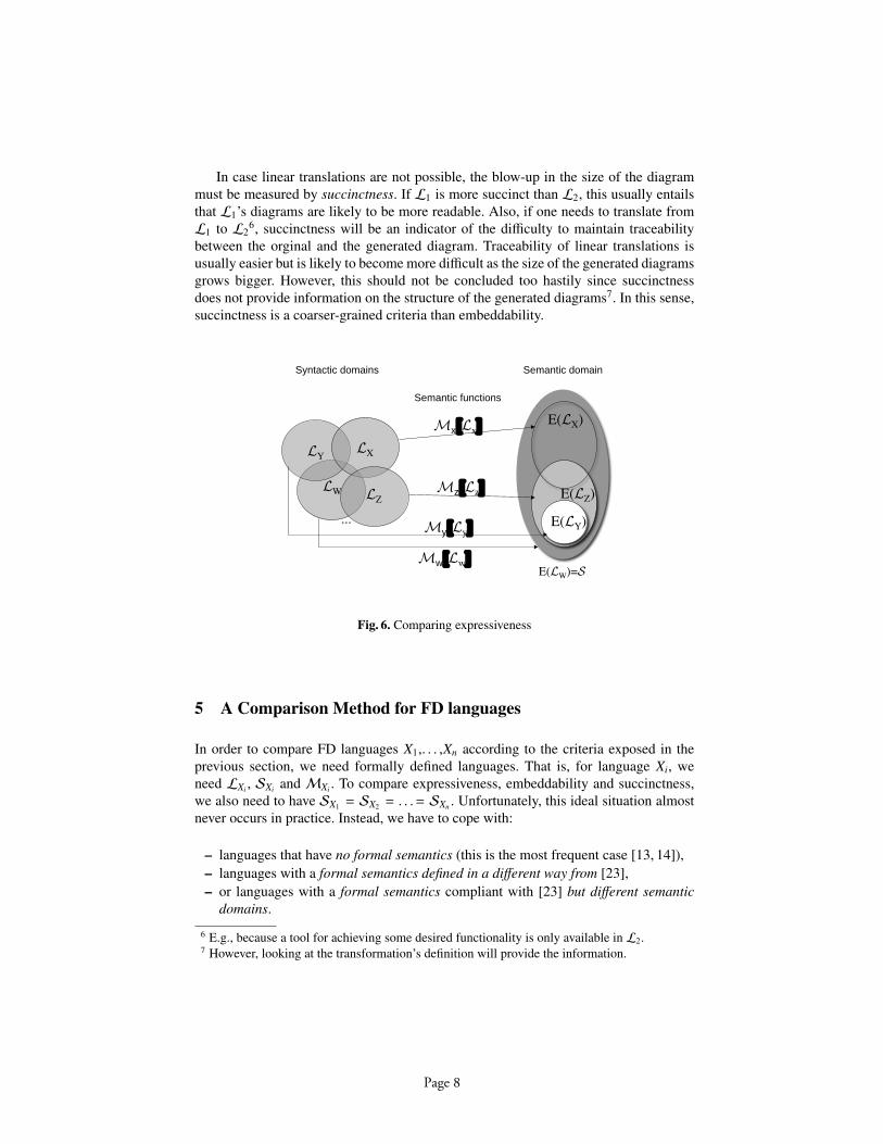
In order to compare FD languages X1,. . . ,Xn according to the criteria exposed in theprevious section, we need formally defined languages. That is, for language Xi, weneed LXi , SXi and MXi . To compare expressiveness, embeddability and succinctness,we also need to have SX1 = SX2 = . . .= SXn . Unfortunately, this ideal situation almostnever occurs in practice. Instead, we have to cope with:
– languages that have no formal semantics (this is the most frequent case [13, 14]),– languages with a formal semantics defined in a different way from [23],– or languages with a formal semantics compliant with [23] but different semantic
domains.
6 E.g., because a tool for achieving some desired functionality is only available in L2.7 However, looking at the transformation’s definition will provide the information.
Page 8

Hence, the overall comparison process should be carried out in two steps: (1) makethe languages suitable for comparison, (2) make the comparisons. We now detail thefirst step.
Let X1 be the language we want to compare with the others (X2, ..., Xn) which, weassume, are fully and clearly formalised according to [23] and have identical semanticdomains. We distinguish three cases:
5.1 Case 1: X1 has no formal semantics
There are two alternatives:
– The first alternative is to define the syntax and semantics for each FD languageindividually following [23]. That is, we define X1 independently from X2, ..., Xn.This is what we did in [11] where we formalised FODA FDs (OFT) [1]. FORMFDs (OFD) [3] are treated the same way in [26].
– The second alternative is to make scale economies and define several languages atonce. In [14], we observed that most of the FD languages largely share the samegoals, the same constructs and, as we understood from the informal definitions, thesame (FODA-inspired) semantics. For this reason, we proposed to define not oneFD language but a family of related FD languages (see Fig. 5). We defined a para-metric abstract syntax, called FFD, in which parameters correspond to variations inLX1 , ...,LXn . This definition follows, but slightly adapts, the principles of Section 3.The semantic domain (PL) and semantic function are common to all FD variants,maximizing semantic reusability. With this method, we are confined to handle lan-guages whose only significant variations are in abstract syntax. For languages withvery different semantic choices, e.g. [19], it is much harder to describe (and justify)the introduction of variation points in the semantics. Then, we should rather followeither the first alternative in Case 1 if the language is informal, or Cases 2 or 3otherwise.
5.2 Case 2: X1 has formal semantics but LX1 , SX1 andMX1 need to be clarified
Another frequent case is when X1 actually has a formal semantics, but irrespective of[23]. That is, we cannot see explicit and self-contained mathematical definitions ofLX1 ,SX1 andMX1 . Typically,LX1 is clear and self-contained, but SX1 andMX1 are not. Mostof the time, the semantics of X1 is given by describing a transformation of X1’s diagramsto another language, say W, which is formal. W does not even need to be a FD language,and usually it is not. Therefore, the semantic domain might be very different from theone intuitively thought of for FDs. The main motivation for formalising this way isusually because W is supported by tools. The problem is that these kinds of “indirect”,or tool-based, semantics complicate the assessment of the language8.
Several proposals of this kind for FDs can be found in recent work [17–22]. Wethus need to reformulate the semantics of those languages. In [15], we treated the FDlanguage proposed by van Deursen and Klint [22] (renamed vDFD) before comparing
8 Even more if W’s semantics also does not follow [23].
Page 9

it to FFD. The main difference w.r.t. Case 1 is that here formalisation decisions areusually much more straightforward since they have already been made. However, theymight be hard to dig out if they are coded in some tool. Also, formalisations are notnecessarily error-free, and errors can thus be discovered when re-formalising [15].
5.3 Case 3: X1 has formal semantics with clear LX1 , SX1 and MX1 butSX1 , SX2 , ...,SXn
The third and last case is when we have a clear and self-contained mathematical defini-tion of L, S andM for all languages (either from the origin, or having previously gonethrough Case 1 or 2) but the semantic domains of the languages differ. We thus needto define a relation between the semantic domains. We met this problem, for instance,when comparing vDFD with FFD [15]. On the one hand, we had SFFD = PL = PPP(sets of sets of nodes), and on the other, SvDFD = OON (lists of lists of nodes). The lat-ter introduces an order relation on features, and one on products. Comparing languageswith different semantic domains is actually possible, but it requires preliminary workwhich is now explained.
Syntactic domains
Semantic domains
Semantic functions
L1
L2
S1
S2T
A
M1
M2
d2
M2 !d2"=
A(M1!d1 ")=
M2!T(d1) "
M1!d1"d
1
Fig. 7. Abstracting a semantic domain
We need to define an abstraction function (A in Fig. 7) whose purpose is to re-move extra information from the richer domains and keep the “core” of the semanticdomain, where we will perform the comparisons. We used such a function to removethe ordering of features and products from SvDFD [15]. However, the question of the rel-evance of this discarded information remains and should be studied carefully. A fairlygeneral case is illustrated in Fig. 7, where domain S1 contains more information thanS2; we then take S2 as the common domain. A removes extra information from ele-ments of S1 and maps them in S2. It then makes sense to look for quasi-translationsT : L1 → L2 between their syntactic domains. They are translations for the abstracted
Page 10
semantics A ◦ M1, and can thus be used to compare languages for expressiveness,embeddability or succinctness. Hence, if we apply T to a diagram d1 in the syntacticdomain L1 we will obtain a diagram d2 in the syntactic domain L2 with the same ab-stracted semantics. Semantically, if we apply the semantic functionM1 to d1 and thenthe abstraction functionA, we will map on the same element of S2 as if we apply T tod1 and thenM2:A(M1[[d1]]) =M2[[T (d1)]].
When applied to more than two languages, this method will create many semanticdomains related by abstraction functions. The abstraction functions can be composedand will describe a category of the semantic domains. At the syntactic level, the transla-tions can also be composed to yield expressiveness and succinctness results. Similarly,the composition of embeddings yields an embedding.
6 Language Evaluation Results
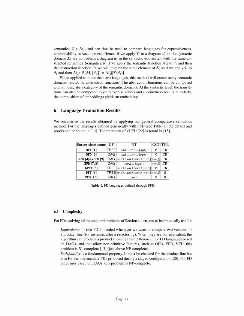
We summarise the results obtained by applying our general comparative semanticsmethod. For the languages defined generically with FFD (see Table 1), the details andproofs can be found in [13]. The treatment of vDFD [22] is found in [15].
Survey short name GT NT GCT TCLOFT [1] TREE and ∪ xor ∪ {opt1} ∅ CROFD [3] DAG and ∪ xor ∪ {opt1} ∅ CR
RFD [4]=VBFD [9] DAG and ∪ xor ∪ or ∪ {opt1} {⇒, |} CREFD [7, 8] DAG card ∪ {opt1} {⇒, |} CRGPFT [5] TREE and ∪ xor ∪ or ∪ {opt1} ∅ CRPFT [6] TREE and ∪ xor ∪ or ∪ {opt1} {⇒, |} ∅
VFD [13] DAG card ∅ ∅
Table 1. FD languages defined through FFD
6.1 Complexity
For FDs, solving all the standard problems of Section 4 turns out to be practically useful:
– Equivalence of two FD is needed whenever we want to compare two versions ofa product line (for instance, after a refactoring). When they are not equivalent, thealgorithm can produce a product showing their difference. For FD languages basedon DAGs, and that allow non-primitive features, such as OFD, EFD, VFD, thisproblem is Π1-complete [13] (just above NP-complete).
– Satisfiability is a fundamental property. It must be checked for the product line butalso for the intermediate FDs produced during a staged configuration [20]. For FDlanguages based on DAGs, this problem is NP-complete.
Page 11
– Model-checking verifies whether a given product (made of primitive features) is inthe product line of a FD. It is not as trivial as expected, because the selection per-formed for non-primitive nodes must be reconstructed. This gives an NP-completeproblem. When recording this selection, the problem becomes linear again.
– Union is useful when parallel teams try to detect feature interference in FDs. Theirwork can be recorded in separate FDs, the union of which will represent the vali-dated products. For FD languages based on DAGs, this problem is solved in lineartime, but the resulting FD should probably be simplified for readability. Intersectionand reduced product are similar.
The complexity results show the role of non-primitive features. On one hand, it isuseful to record them to accelerate the checking of products. However, they should notbecome part of the semantics since this would restrict the expressiveness and stronglyreduce the possible transformations of diagrams.
6.2 Expressiveness
The distinction between languages that only admit trees and the ones that allow shar-ing of features by more than one parent (DAGs or vDFD) turns out to be important.While tree-shaped languages are usually incomplete, OFD [3] are already expressivelycomplete without the constraints, and thus a fortiori RFD [4], EFD [7, 8] and VFD [13].vDFD are “almost” trees in that only terminal features (i.e. the leaves) can have multipleparents (justifications), but this is sufficient to obtain expressive completeness.
In contrast, tree-shaped diagrams turned out to be expressively incomplete; in par-ticular, OFT [1] cannot express disjunction. This justifies a posteriori the proposal [9](VBFD) to add the or operator to OFT. But even so, we do not attain expressive com-pleteness: this language is still unable to express card3[2..2], the choice of two featuresamong three9. This justifies similarly the proposal [7] (EFD) to use the card operators.Both [9] and [7] also propose to allow DAGs: this extension alone, as we have seen,ensures expressive completeness. But we will see below better justifications in terms ofembeddability rather than succinctness.
When designing a FD language, is thus essential to have more than trees to reach ex-pressive completeness. Trees, however, are easier to understand and manipulate becausethey have a compositional semantics. vDFD [22] manage to have both advantages.
6.3 Embeddability
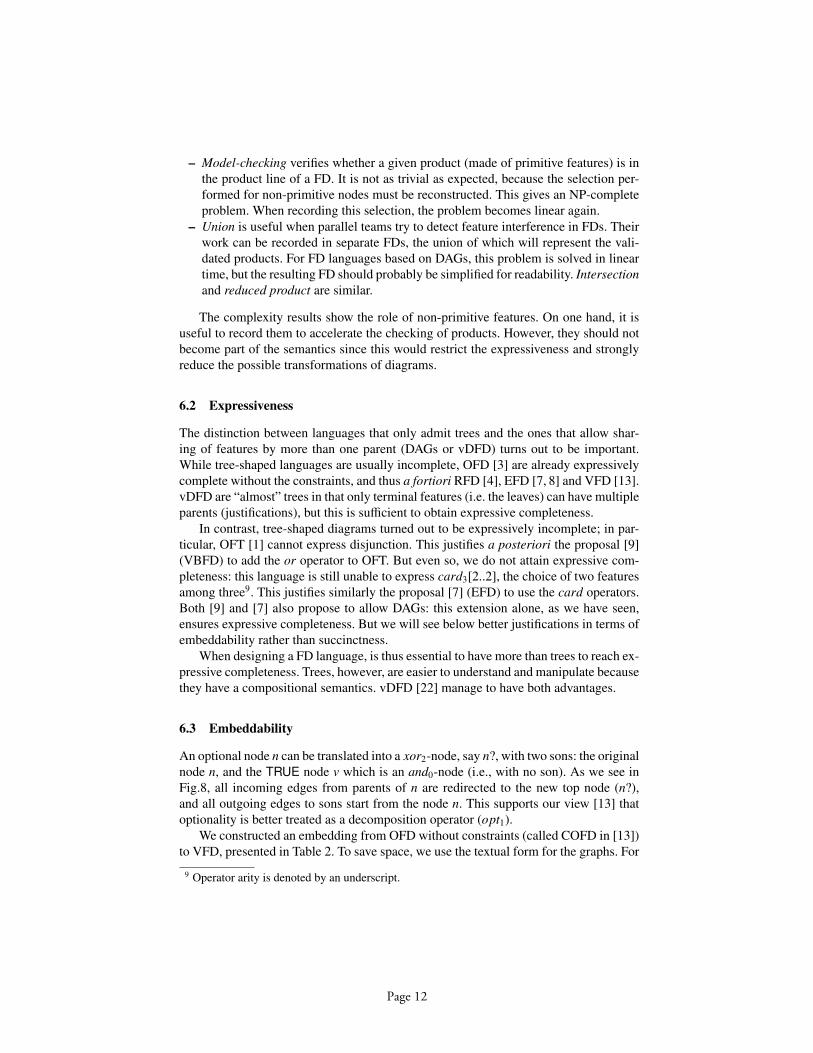
An optional node n can be translated into a xor2-node, say n?, with two sons: the originalnode n, and the TRUE node v which is an and0-node (i.e., with no son). As we see inFig.8, all incoming edges from parents of n are redirected to the new top node (n?),and all outgoing edges to sons start from the node n. This supports our view [13] thatoptionality is better treated as a decomposition operator (opt1).
We constructed an embedding from OFD without constraints (called COFD in [13])to VFD, presented in Table 2. To save space, we use the textual form for the graphs. For
9 Operator arity is denoted by an underscript.
Page 12

n
n?
n V
Fig. 8. Graphical embedding of redundant optional node (in OFD concrete syntax)
instance, a node bearing a xorm operator is translated to a node bearing a cardm[1 . . . 1]operator. In the next section, we will consider how those embeddings increase the sizeof the graph. Here we see that the VFD resulting from the embedding of a COFD di-agram has the same size. This result indicates that card-nodes proposed by [7] canembed all the other constructs. We proposed thus to use them systematically insidetools. We slightly differ from [7] that also uses optional edges: these can be modelledby card1[0..1]-nodes and would be harmfully redundant. We proposed VFD to elimi-nate this slight drawback. Please note that this latter suggestion only concerns abstractsyntax. In the concrete syntax, it is probably a good idea to keep optional nodes as thiswould decrease the size and visual complexity of the diagrams.
Instead of . . . write . . .opt1( f ) card1[0 . . . 1]( f )
xorm( f1, . . . , fm) cardm[1 . . . 1]( f1, . . . , fm)ands( f1, . . . , fs) cards[s . . . s]( f1, . . . , fs)
Table 2. Embedding COFD into VFD
6.4 Succinctness
When translations are not linear, it is still interesting to compute the increase in size ofthe graph, as measured by succinctness. RFD and OFD are of similar succinctness, butwhen translating VFD or EFD to OFD we translate a cardk-node to a OFD graph of sizeO(k2) [13]. A VFD of size O(k) could contain k cardk-nodes, giving a cubic translationat the end: COFD ≤ O(VFD3). This result indicates again that card-nodes are a usefuladdition, but for different reasons than presented in [7].
7 Discussion
The main limitation of our work is explicit in its scope: we address only formal seman-tics-related properties. In order not to over-interpret our conclusions, one should keepcomprehensive view of model quality in mind. With respect to SEQUAL (Section 2),in order to be accurate and effective, we deliberately chose to address only part of the
Page 13
required qualities: Domain appropriateness is addressed by looking at language expres-siveness. Comprehensibility appropriateness is addressed by looking at embeddabilityand succinctness. Technical actor interpretation appropriateness is addressed by look-ing at complexity and also embeddability and succinctness. Furthermore, our criteriacover only part of each of the three qualities. Future research should therefore devotesimilar attention to other qualities and criteria.
In contrast, a more holistic (quality-wise) attempt to compare FD languages is re-ported in [27]. It is specific though in the sense that it concerns the usage of FDs ina particular company, for a given kind of project. This leads us to point out that thenotion of a “good” modelling language is only relative to the context of use of the lan-guage. The priorities to be put on the expected qualities and criteria are very likely tobe different from one company, or projet, to another. This could lead us to relativisein some contexts the importance of formality. Still, we think that for FDs formality isvery likely to deliver more than it will cost since (1) languages are relatively simple,(2) formality can be made largely transparent to the users (hidden behind a graphicalconcrete syntax), (3) the automation possibilities are many [13, 14, 28], and (4) correctFDs are mission-critical company assets that should suffer no ambiguity.
SEQUAL also helps identify another limitation: for now, we have only looked atlanguage quality adopting a theoretical approach. A complementary work is to investi-gate models empirically. In Section 2, we emphasised the difficulty of such an endeav-our because of the limited availability of “real” FDs. Nevertheless, we do not considerit impossible and can certainly learn a lot by observing how practitioners create and useFDs. Although we have focussed on studying theoretical properties of FD languages,we need to recognise that no formal semantics, nor criteria, can ever guarantee by itselfthat the languages help capture the right information (neither too little, nor too much)about the domain being modelled. Only empirical research can help us give a convinc-ing answer to this other aspect of domain appropriateness.
A threat to validity is that all our reasoning (comparisons, demonstrations of theo-rems) was done by humans only, no tools. Human errors, miss- or over-interpretationsare thus possible. Also, our formalisations were made only by considering the publisheddocuments, and without contacting the authors for clarifications, nor testing their tools.However, making L, S andM explicit, we open the way for constructive discussion.
Finally, our method is yet to be applied to some relevant FD language proposals [16–21]. This is a prioritary topic of future work.
8 Conclusion
The bad news confirmed by this paper is that current research on variability modellingis fragmented. Existing research in the field is characterised by a growing number ofproposals and a lack of accurate comparisons between them. In particular, the formalunderpinnings of feature diagrams need more careful attention.
The nocuous consequences of this situation are: (1) the difficulty for practitioners tochoose appropriate feature modelling techniques, (2) an increased risk of ambiguity inmodels, (3) underdeveloped, suboptimal or unsafe (i.e., not proved correct) tool supportfor reasoning on feature diagrams.
Page 14

The good news that this paper delivers is that there are remedies to this situation.The ones that we propose are: (1) a global quality framework (e.g. Krogstie et al.’sSEQUAL) to serve as a roadmap for improving the quality of feature modelling tech-niques; (2) a set of formally defined criteria to assess the semantics-related qualities offeature diagram languages; (3) a systematic method to formalise these languages andmake them ready for comparison and efficient tool automation; and (4) a first set ofresults obtained from the application of this systematic method on a substantial part ofthe feature modelling languages encountered in the literature.
Although the road ahead is still quite long, we are confident that the communitycan take profit of our proposal. It could be used for example as part of an arsenal toelaborate a standard feature modelling language. This standard would not suffer fromambiguity, and its formal properties (among others) would be well known, allowingto devise proved correct efficient reference algorithms. A similar approach could alsobe transposed to cognate areas where existing modelling techniques face similar chal-lenges. In particular, we think of goal modelling techniques.
References
1. Kang, K., Cohen, S., Hess, J., Novak, W., Peterson, S.: Feature-Oriented Domain Analysis(FODA) Feasibility Study. Technical Report CMU/SEI-90-TR-21, Software EngineeringInstitute, Carnegie Mellon University (1990)
2. Cohen, S., Tekinerdogan, B., Czarnecki, K.: A case study on requirement specification:Driver Monitor. In: Workshop on Techniques for Exploiting Commonality Through Variabil-ity Management at the Second International Conference on Software Product Lines (SPLC2).(2002)
3. Kang, K.C., Kim, S., Lee, J., Kim, K., Shin, E., Huh, M.: FORM: A feature-oriented reusemethod with domain-specific reference architectures. Annals in Software Engineering 5(1998) 143–168
4. Griss, M., Favaro, J., d’Alessandro, M.: Integrating Feature Modeling with the RSEB. In:Proceedings of the 5th International Conference on Software Reuse (ICSR’98), Vancouver,BC, Canada (1998) 76–85
5. Eisenecker, U.W., Czarnecki, K.: Generative Programming: Methods, Tools, and Applica-tions. Addison-Wesley (2000)
6. Eriksson, M., Borstler, J., Borg, K.: The PLUSS Approach - Domain Modeling with Fea-tures, Use Cases and Use Case Realizations. In: Proceedings of the 9th International Con-ference on Software Product Lines (SPLC 2005). (2005) 33–44
7. Riebisch, M., Bollert, K., Streitferdt, D., Philippow, I.: Extending Feature Diagrams withUML Multiplicities. In: Proceedings of the Sixth Conference on Integrated Design andProcess Technology (IDPT 2002), Pasadena, CA (2002)
8. Riebisch, M.: Towards a More Precise Definition of Feature Models. Position Paper. In:M. Riebisch, J. O. Coplien, D, Streitferdt (Eds.): Modelling Variability for Object-OrientedProduct Lines (2003)
9. van Gurp, J., Bosch, J., Svahnberg, M.: On the Notion of Variability in Software ProductLines. In: Proceedings of the Working IEEE/IFIP Conference on Software Architecture(WICSA’01). (2001)
10. Moody, D.L.: What Makes a Good Diagram? Improving the Cognitive Effectiveness ofDiagrams in IS Development. In: Proceedings of the 15th international conference in Infor-mation Systems Development (ISD 2006). (2006)
Page 15
11. Bontemps, Y., Heymans, P., Schobbens, P.Y., Trigaux, J.C.: Semantics of FODA FeatureDiagrams. In Mannisto, T., Bosch, J., eds.: Proceedings of Workshop on Software VariabilityManagement for Product Derivation: Towards Tool Support, Boston (2004) 48–58
12. Bontemps, Y., Heymans, P., Schobbens, P.Y., Trigaux, J.C.: Generic Semantics of FeatureDiagrams Variants. In: Proceedings of the 8th International Conference on Feature Interac-tions in Telecommunications and Software Systems(ICFI), IOS Press (2005) 58–77
13. Schobbens, P.Y., Heymans, P., Trigaux, J.C., Bontemps, Y.: Generic semantics of featurediagrams. Computer Networks (2007) special issue on feature interactions in emerging ap-plication domains 51 (2007) 456–479
14. Schobbens, P.Y., Heymans, P., Trigaux, J.C., Bontemps, Y.: Feature Diagrams: A Surveyand A Formal Semantics. In: Proceedings of the 14th IEEE International RequirementsEngineering Conference (RE’06), Minneapolis, Minnesota, USA (2006) 139–148
15. Trigaux, J.C., Heymans, P., Schobbens, P.Y., Classen, A.: Comparative semantics of FeatureDiagrams : FFD vs vDFD. In: Proceedings of Workshop on Comparative Evaluation inRequirements Engineering (CERE’06), Minneapolis, Minnesota, USA (2006)
16. Asikainen, T., Mannisto, T., Soininen, T.: A Unified Conceptual Foundation for FeatureModelling. In: Proceedings of the 10th International Software Product Line Conference.(2006) 31–40
17. Batory, D.S.: Feature Models, Grammars, and Propositional Formulas. In: Proceedings ofthe 9th International Conference on Software Product Lines (SPLC 2005). (2005) 7–20
18. Benavides, D., Ruiz-Cortes, A., Trinidad, P.: Automated Reasoning on Feature Models.LNCS, Advanced Information Systems Engineering: Proceedings of the 17th InternationalConference, CAiSE 2005 3520 (2005) 491–503
19. Czarnecki, K., Helsen, S., Eisenecker, U.: Formalizing Cardinality-based Feature Modelsand their Specialization. Software Process: Improvement and Practice 10 (2005) 7–29
20. Czarnecki, K., Helsen, S., Eisenecker, U.: Staged Configuration Using Feature Models.Software Process Improvement and Practice, special issue on Software Variability: Processand Management 10 (2005) 143 – 169
21. Sun, J., Zhang, H., Li, Y.F., Wang, H.: Formal Semantics and Verification for Feature Model-ing. In: Proceedings of the 10th IEEE International Conference on Engineering of ComplexComputer Systems, ICECCS 2005. (2005) 303–312
22. van Deursen, A., Klint, P.: Domain-Specific Language Design Requires Feature Descrip-tions. Journal of Computing and Information Technology 10 (2002) 1–17
23. Harel, D., Rumpe, B.: Meaningful Modeling: What’s the Semantics of “Semantics”? IEEEComputer 37 (2004) 64–72
24. Krogstie, J.: Using a semiotic framework to evaluate UML for the development of models ofhigh quality. Unified Modeling Language: System Analysis, Design and Develoment Issues,IDEA Group Publishing (2001) 89–106
25. Krogstie, J., Sindre, G., Jørgensen, H.: Process Models Representing Knowledge for Action:a Revised Quality Framework. Eur. J. Inf. Syst. 15 (2006) 91–102
26. Heymans, P., Schobbens, P.Y., Trigaux, J.C., Matulevicius, R., Bontemps, Y., Classen, A.:Evaluating Formal Properties of Feature Diagrams. Technical report, University of Namur(2006)
27. Djebbi, O., Salinesi, C.: Criteria for Comparing Requirements Variability Modeling Nota-tions for Product Lines. Workshop on Comparative Evaluation in Requirements Engineering(CERE’06) 0 (2006) 20–35
28. Benavides, D., Ruiz-Cortes, A., Trinidad, P., Segura., S.: A Survey on the Automated Anal-yses of Feture Models. In: Jornadas de Ingenierıa del Software y Bases de Datos (JISBD).(2006)
Page 16
OntologyBased Software Reliability Modelling
Jiehan Zhou, Eila Niemelä, Antti Evesti
VTT Technical Research Centre of FinlandKaitoväylä 1, 90571 Oulu, Finland
Email:{firstname.surname}@vtt.fi
Abstract. Reliability has become a major concern for softwareintensivesystems. This paper proposes a novel ontologybased method for softwarereliability modelling, including a software reliability ontology and an ontologybased software reliability modelling system. The software reliability ontology isanalysed and developed for software reliability engineering with respect todomains of reliability measurement processes, methods, models, organization,and tools. The ontologybased software reliability modelling system validatesthe ontologybased method with presentations of the system infrastructure, thesystem implementation techniques, and the system application cases.
1. Introduction
Modern society is permeated by softwareintensive systems, such as consumerelectronics, buildings, automobiles, and aircraft. The size and complexity of softwareintensive systems have grown dramatically during the past decade, and the trend iscertain to continue with the emergence of serviceoriented architectures and Webservices [1, 2]. Meanwhile, software reliability has become a major concern forsoftwareintensive systems.
‘Software reliability’ refers to the probability of failurefree operation of acomputer program in a specified environment over a specified period of time [35]. Inthe interest of increasing software reliability, a number of studies have been carriedout on reliability modelling [68], reliability estimation, and prediction toolsdevelopment [9, 10]. At the same time, several books [4, 5, 11] have been publishedfor the purposes of reliability education and training. For the sake of brevity, whenspeaking of ‘reliability’ below, we are referring to software reliability.
In what follows, we will explore a novel ontologybased method for reliabilitymodelling, including a reliability ontology and an ontologybased reliabilitymodelling system. To the best of our knowledge, there are only few reports availableon the topic. The remainder of the paper is organized as follows: Section 2 outlines aset of key concepts related to ontologybased reliability modelling. Section 3 definesthe objectives of building a reliability ontology. In Section 4, different ontologyengineering methods are compared and a guideline is presented for reliabilityontology modelling. Section 5 examines reliability domains and develops thereliability ontology. The reliability modelling system is presented in Section 6, alongwith the system infrastructure, system implementation techniques, and some system
Page 17

application cases. Section 7 draws the conclusions from our discussion and anticipatesdirections for future research.
2. Concepts
Ontology is a shared knowledge standard or knowledge model explicitly definingprimitive concepts, relations, rules, and their instances. Ontology can be used forcapturing, structuring, and enlarging explicit and tacit knowledge across people,organizations, and computer and software systems [12].
Reliability ontology consists of concepts and their relationships related to the topicof reliability engineering and aimed at facilitating the work of reliability experts inmanaging and developing reliability knowledge.
Ontologybased reliability design is an ontologybased method that providesreliability experts with the reliability ontology and associated management tools forfacilitating software reliability definition and measurement.
3. Objectives of the reliability ontology development
The intended uses of the reliability ontology include the following applicationcontexts:§ Management and development of reliability knowledge. By making use of the
reliability ontology, the software customer can understand reliabilityterminologies explicitly, assess the reliability of the provided software orservice, and fluently communicate with reliability experts. The reliabilityexperts can adopt, adjust, and choose reliability models based on the reliabilityontology.§ Support for computeraided reliability estimation and prediction. Once the
reliability ontology is built into software programs (socalled ontologybasedprograms), these programs can be enhanced by customizing reliabilitymeasurement procedures and by providing a common reliability developmentand management framework.§ Support for reliability knowledge management in software engineering.
Component and service reliability becomes a critical factor influencingcomponentbased and serviceoriented software development. The reliabilityontology promises to provide software community with a commoncommunication platform for addressing reliability knowledge, and to facilitatereliabilitybased service discoveries and compositions.
Page 18
4. Ontology engineering and reliability ontology modelling
4.1 Ontology engineering methodologies
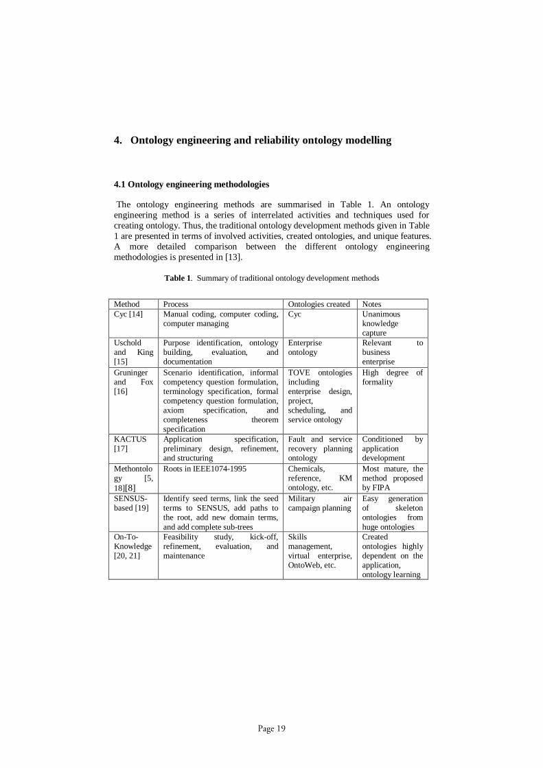
The ontology engineering methods are summarised in Table 1. An ontologyengineering method is a series of interrelated activities and techniques used forcreating ontology. Thus, the traditional ontology development methods given in Table1 are presented in terms of involved activities, created ontologies, and unique features.A more detailed comparison between the different ontology engineeringmethodologies is presented in [13].
Table 1. Summary of traditional ontology development methods
Method Process Ontologies created NotesCyc [14] Manual coding, computer coding,
computer managingCyc Unanimous
knowledgecapture
Uscholdand King[15]
Purpose identification, ontologybuilding, evaluation, anddocumentation
Enterpriseontology
Relevant tobusinessenterprise
Gruningerand Fox[16]
Scenario identification, informalcompetency question formulation,terminology specification, formalcompetency question formulation,axiom specification, andcompleteness theoremspecification
TOVE ontologiesincludingenterprise design,project,scheduling, andservice ontology
High degree offormality
KACTUS[17]
Application specification,preliminary design, refinement,and structuring
Fault and servicerecovery planningontology
Conditioned byapplicationdevelopment
Methontology [5,18][8]
Roots in IEEE10741995 Chemicals,reference, KMontology, etc.
Most mature, themethod proposedby FIPA
SENSUSbased [19]
Identify seed terms, link the seedterms to SENSUS, add paths tothe root, add new domain terms,and add complete subtrees
Military aircampaign planning
Easy generationof skeletonontologies fromhuge ontologies
OnToKnowledge[20, 21]
Feasibility study, kickoff,refinement, evaluation, andmaintenance
Skillsmanagement,virtual enterprise,OntoWeb, etc.
Createdontologies highlydependent on theapplication,ontology learning
Page 19
4.2 Reliability ontology modelling
Based on the summary of ontology engineering methods and a typical ontologyengineering process given in [8], we can propose a guideline for creating thereliability ontology:
Step 1. Determine the domain of the reliability ontology. The reliability ontologycovers reliability process, method, model, specification, tool, and organizationdomains.
Step 2. Consider reusing existing reliability ontologies. Unfortunately, noreliability ontologies exist as of yet. Information on reliability is distributed thoughbooks and research publications.
Step 3. Enumerate important reliability concepts. It is useful to start with classicalworks on reliability engineering, creating a list of all the concepts that reliabilityexperts would prefer to use.
Step 4. Define the reliability concept hierarchy. A topdown development processmay be used in this step. First we define the most general reliability concepts(process, method, and specification) and the subsequent specialisation of theseconcepts (reliability definition and operational profile development).
Step 5. Define the reliability properties. In general, there are two types ofreliability properties: internal properties and external properties. The internalproperties indicate properties belonging to the concept itself, such as the name of aprocess. The external properties indicate relationships between concepts, such as themethod of a process.
Step 6. Create reliability instances. We define an individual reliability instance interms of a concept and its properties.
5. Reliability ontology design
5.1. Reliability ontology domains
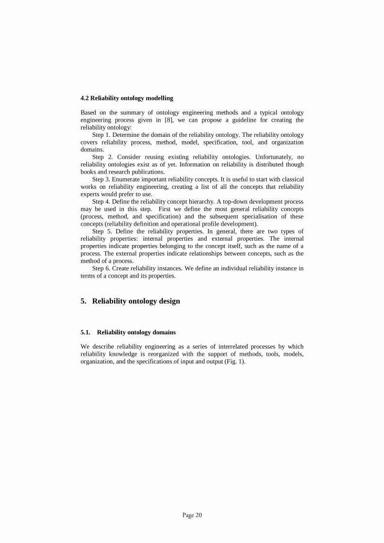
We describe reliability engineering as a series of interrelated processes by whichreliability knowledge is reorganized with the support of methods, tools, models,organization, and the specifications of input and output (Fig. 1).
Page 20

tool
mod
elm
etho
d
orga
niza
tion
Fig. 1. Reliability ontology domainsThe reliability process refers to reliability engineering processes, consisting of five
activities: a) definition of necessary reliability, b) development of operational profiles,c) preparation for test, d) execution of test, and e) application of failure data to guidedecisionmaking.
The reliability organization is in charge of executing the processes. Reliabilitymeasurement is usually carried out in an operation organization. The commonlyinvolved roles are the enduser for executing the software, the manager for resourceallocation, the system engineers for tailoring reliability procedures, and the qualityassurance engineers for running tools and collecting failure data.
The reliability method identifies a way for the organization to undertake reliabilityprocesses in terms of costefficiency and purposespecification.
The reliability models are chosen and used in any given applications depending onthe purpose of the application. A software reliability model usually has the form of arandom process that describes the behaviour of failures over time.
Reliability tools are computer programs or simulations used in software reliabilitymeasurement.
Reliability specification of input and output refers to the input and output data forthe reliability process. This data can take the form of tables, files, and graphics.
5.2. Concepts hierarchy
A reliability concepts hierarchy is a hierarchical concept classification. Fig. 2describes these concepts in detail.
Page 21

Fig. 2. Reliability concept hierarchy
Reliability process conceptsDefining reliability means quantitative reliability definition of a software system,
which in turn makes it possible for reliability experts to balance customer needs forreliability, delivery date, and cost. The reliability definition mainly consists of thesubprocesses of reliability severity definition, failure intensity objective setting, andreliability strategies engineering.
The operational profile development mainly consists of the subprocesses ofidentifying the initiator of operations, listing the operations, determining the operationoccurrence, and determining the occurrence probabilities.
In preparing for test, the operational profile information is applied to planningefficient testing, including preparation of test cases and test procedures.
In executing the test, the test cases and test procedures are used in such a way thatthe desired goal of the efficient test can be achieved. The execution of tests involvesthree main activities: allocating test time, invoking the tests, and identifying failuresthat occur.
In failure data interpretation, the predicted reliability is compared with the setreliability objectives for guiding systemreliability decision making, e.g., accepting orrejecting an acquired component or a software system.
Reliability method conceptsA method describes how to conduct a process efficiently and effectively. The
reliability method mainly consists of the methods used in the reliability processes.
Page 22

The following lists the methods that are presented in [5], including operational profiledevelopment methods and failure interpretation methods.
Operational profile development methods include tabular representation andgraphical representation. Tabular representation generally works better for systemswhose operations have few (often only one) attributes. Graphical representation isgenerally better suited for software the operations of which have multiple attributes.
Failure interpretation methods. There are two approaches for interpreting softwaresystem reliability: failure intensity trend and reliability chart demonstration. Thefailure intensity trend method estimates the failure intensity over all severity classesand across all operational modes against time. The reliability chart method is used incertification tests in which each failure is plotted and labelled with its severity class.
Specification conceptsSpecifications are the input or output of the reliability measurement processes,
such as operational profiles, test cases, and reliability metrics.An operational profile is an operation scenario that describes typical uses of the
system, consisting of an operation list, the operation occurrence, and the operationoccurrence probability. The operation list is a tabular or graphical representation ofthe operations each initiator produces. The operation occurrence refers to theoccurrence rates of the operation. The operation occurrence is commonly measuredwith respect to time. The operation occurrence probability is the ratio of the operationcompared to the total occurrence rates.
A test case is the partial specification of a run through the naming of its direct inputvariables and the values of these variables during the preparations for the test process.
Reliability metrics are measurable, quantitative software attributes, consistingmainly of the following items:§ A failure is the departure of program behaviour from user requirements
during execution. A failure confidence interval represents a range of valueswithin which a parameter is expected to lie with a certain statistical degree ofprobability.
§ A failure severity class is a set of failures that affect users to the same degreeor level. The severity is often related to the criticality of the operation thatfails [5, 11].
§ A failure objective is set for the software system.§ Failure strategies include fault prevention, fault removal, and fault tolerance.
Fault prevention uses requirements, design, and coding technologies andprocesses to reduce the number of faults. Fault removal uses code inspectionand development testing to remove faults in the code once it is written. Faulttolerance reduces the number of failures that occur, by detecting andcountering deviations in program execution that may lead to failures [5].
§ The failure data refers to the metric of representing failure occurrence,including the timebased class and the failurebased class. The failurebasedclass represents failure occurrence by indicating the frequency of the failuresexperienced within a time interval. The timebased class represents failureoccurrence by determining the time interval between failures.
Model concepts
Page 23

A reliability model usually has the form of a failure process that describes thebehaviour of failures with time, also called failure random process. The possibilitiesfor different mathematical forms to describe the failure process are almost limitless[5]. The following lists two classes of reliability models used in software architecturereliability evaluation.
The statebased models use a control flow graph to represent the architecture of thesystem. It is assumed that the transfer of control between components has a Markovproperty, which means that, given what is known of the component in control at anygiven time, the future behaviour of the system is conditionally independent of its pastbehaviour [22]. Statebased models consist of the states, or externally visible modesof operation, that must be maintained, and the state transitions labelled with systeminputs and transition probabilities. Statebased models can be used even if the sourcecode of the component is not available. Statebased model instances include: theLittlewood model [23], the Cheung model [24], the Laprie method [25], the Kubatmethod [26], the Gokhale et al. method [27], and the Ledoux method [28].
The pathbased models are based on the same common steps as the statebasedmodels [22]. In addition, the pathbased models enable one to specify, with the helpof the simulation, component reliability estimations [29]. Pathbased model instancesinclude: the Shooman model [30], the Krishnamurthy and Mathur model [31], and theYacoub et al. model [32].
Tool conceptsThis section presents some reliability evaluation tool instances, such as SMERFS
[4], CASRE[9], SoRel [33], and AgenaRisk [34].SMERFS (Statistical Modelling and Estimation of Reliability Functions for
Systems) [4] allows the end user to enter data, to edit and/or transform the data ifnecessary, to plot the data, to select an appropriate model to fit the data, to determinethe fit of the model using both statistical and graphical techniques, to make variousreliability predictions based upon the fitted model, and to try different models if theinitial model proves inadequate.
CASRE (Computer Aided Software Reliability Estimation) [9, 35] is an extensionof SMERFS. Users are guided through the selection of a set of failure data and theexecution of a model with the assistance of selectively enabling pulldown menuoptions.
SoRel [33] is a tool for software (and hardware) reliability analysis and predictionthat provides qualitative and quantitative elements concerning, for instance, a) theevolution of the reliability in response to the debugging effort; b) the estimation of thenumber of failures for the subsequent time periods to allow test effort planning andthe assignment of the numerical importance by the test and/or maintenance team; andc) the prediction of reliability such as the mean time to failure, the failure rate, andthe failure intensity.
AgenaRisk [34] is a risk assessment and risk analysis tool. It arms users with thelatest algorithms that allow quantification of uncertainty and offer models forprediction, estimation, and diagnosis, all made accessible via a sophisticated graphicaluser interface.
Additional software reliability modelling tools and programs are surveyed in [36]and listed on the Web [37].
Page 24

5.3. Properties definition
We categorize the reliability property into internal property and external property.The internal property describes the internal structure and attributes of concepts, andthe external property describes the relationships between concepts. For an internalproperty, we must determine which concept it describes; for instance,specificationName is one of the internal properties of the concept Specification. Foran external property, we must determine the class(es) of which the values of theproperty will be members, and the class(es) that will have the property as a member;for instance, hasMethod is an internal property between concepts of Method andProcess. The initial reliability properties are defined in Fig. 3.
Fig. 3. Reliability properties definitionSystem properties
systemName: a system has a name.hasSystemReliability: a system has a reliability objective.hasOperationProfile: a system has an operational profile.hasReliabilityObjective: a system has a failure intensity objective or reliabilityobjective.hasSpecification: a system has at least one specification.
Process propertiesprocessName: a process has a name.hasSubprocess: a process could have two or more subprocesses.isBefore/isAfter/isSimutaneous: a process can occur before/after/simultaneouslywith at least one other process.hasMethod: a process could have a method.hasTool: a process could have a supporting tool.hasModel: a process could have a model.hasInput: a process could have an input specification.hasOutput: a process could have an output specification.
Tool Properties
Page 25

toolName: a tool must have a name.hasFunctionalDescription: a tool must have a functional description.hasProvider: a tool must have a provider.
Model propertiesmodelName: a model must have a name.hasFailureData: a model must have failure data for input.hasRandomProcess: a model must have a random process.
Specification propertiesspecificationName: a specification must have a name.versionStatus: a specification has a version status.
Method PropertiesmethodName: a method must have a name.
6. Ontologybased reliability modelling system
6.1. System infrastructure
Suppose a company is planning to introduce a new software product of HomeSecurityfor monitoring home environment information automatically. The system consists of aset of home automation service components (e.g. a video capture service, a lightswitch service, and an alarming service). Those components must satisfy qualityrequirements to some degree. For example, the alarm service needs a high reliabilityin the HomeSecurity system. In order to facilitate product reliability measurement, wehave designed an ontologybased reliability modelling system, which has the primaryfunctions of managing the software reliability ontology and designing softwaresystem reliability (Fig. 4).
Fig. 4. Ontologybased reliability modelling system
Page 26

The system level consists of an ontology modelling framework and an applicationdevelopment environment. The ontology modelling framework is used for reliabilityontology modelling by allowing reliability experts to create reliability ontology andload reliability ontology files. The application development environment is anapplication development platform used for building, deploying, and managingapplication software across the lifecycle.
The middleware level consists of APIs (Application Programming Interfaces)responsible for handling reliability ontology, including build, access, display, andupdate reliability ontology.
The application level includes reliability ontology management and reliabilitymodelling. The reliability ontology management application is responsible for reading,writing, and visualizing reliability ontology documents written in Web ontologylanguages (e.g., RDF [38], and OWL [39]). The reliability ontology managementfurther enables reliability experts to make semantic knowledge queries aboutreliability. The reliability modelling application supports software system reliabilitymeasurement processes, including definition of reliability, development of operationprofiles, preparation for and execution of reliability test, and interpretation of failuredata.
6.2. System implementation
In the implementation of the ontologybased reliability modelling system, we haveexplored and adopted the following technonologies: Eclipse for the applicationdevelopment environment, OWL for the reliability ontology modelling, and Jena forthe reliability ontology file management.§ Eclipse for the ontologybased system development environment [40]. Eclipse is
an open source development platform comprised of extensible frameworks andtools for building, deploying, and managing software across the lifecycle. Eclipsepossesses a powerful modelling framework and code generation facility (EclipseModelling Framework, or EMF). The EMF provides the foundation forinteroperability with other EMFbased tools and applications.
§ OWL (Web Ontology Language) [41] for the reliability ontology modelling.OWL enables greater machine interpretability of Web content than XML, RDF,or RDF Schema. OWL further provides additional vocabulary along with formalsemantics, and adds qualifiers for describing properties and classes, such asdisjointness, cardinality, and symmetry. The reliability OWL documents refer tofiles written with the OWL language.
§ Jena API [42] for accessing reliability ontology OWL documents. Jenaframework provides rich OWL APIs for reading and writing reliability ontologyOWL documents. These can be used to save and read the reliability ontology inthe form of files.
Page 27
6.3. Application cases
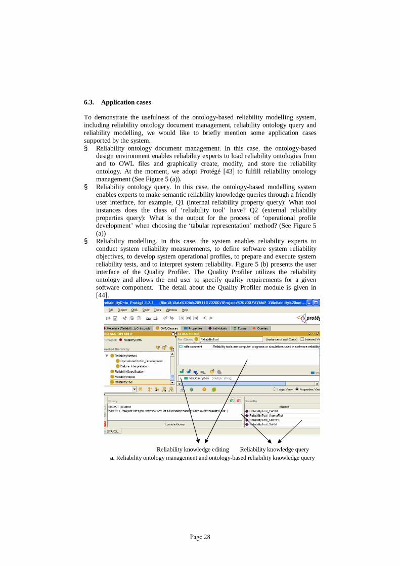
To demonstrate the usefulness of the ontologybased reliability modelling system,including reliability ontology document management, reliability ontology query andreliability modelling, we would like to briefly mention some application casessupported by the system.§ Reliability ontology document management. In this case, the ontologybased
design environment enables reliability experts to load reliability ontologies fromand to OWL files and graphically create, modify, and store the reliabilityontology. At the moment, we adopt Protégé [43] to fulfill reliability ontologymanagement (See Figure 5 (a)).
§ Reliability ontology query. In this case, the ontologybased modelling systemenables experts to make semantic reliability knowledge queries through a friendlyuser interface, for example, Q1 (internal reliability property query): What toolinstances does the class of ‘reliability tool’ have? Q2 (external reliabilityproperties query): What is the output for the process of ‘operational profiledevelopment’ when choosing the ‘tabular representation’ method? (See Figure 5(a))
§ Reliability modelling. In this case, the system enables reliability experts toconduct system reliability measurements, to define software system reliabilityobjectives, to develop system operational profiles, to prepare and execute systemreliability tests, and to interpret system reliability. Figure 5 (b) presents the userinterface of the Quality Profiler. The Quality Profiler utilizes the reliabilityontology and allows the end user to specify quality requirements for a givensoftware component. The detail about the Quality Profiler module is given in[44].
a. Reliability ontology management and ontologybased reliability knowledge queryReliability knowledge editing Reliability knowledge query
Page 28

b. Ontologybased reliabilityaware software modellingFig.5. Reliability ontologybased applications
7. Conclusions and future work
Growing attention has been given to the quality driven software design, increasingsoftware complexity and emerging serviceoriented architectures. At present, onlyfew studies exist on ontologybased software reliability design. In the foregoing wehave explored and proposed a novel ontologybased method for designing softwarereliability. The ontologybased method aims to provide reliability experts with areliability ontology and related computeraided tools for facilitating reliabilityengineering. First, the concepts related to reliability were specified. Next, studiesassociated with ontology engineering were discussed, including the objectives ofcreating a reliability ontology, ontology engineering methods, and guidelines forcreating a reliability ontology. Further, by identifying the knowledge scopes ofreliabilityaware software design, the reliability ontology was designed primarily withrespect to reliability concepts and properties. The experiences gained in developingthe ontologybased reliability design tool were also presented. Future work will focuson elaborating the ontologybased method in the following aspects:§ Continuing the development of reliability ontology, along with the mining
and refining of the reliability concepts and properties.
Page 29

§ Applying the method to software architecture design. This work will extendthe existing reliability ontology by developing and merging a softwarearchitecture ontology and developing associated applications supportingreliabilityaware software architecture design.
§ Elaborating the implementation of the ontologybased reliability modellingsystem for specified technical features.
References
1. Kreger, H.: Web Service Conceptual Architecture (WSCA 1.0). www3.ibm.com/software/solutions/webservices/pdf/WSCA.pdf, 2001.2. WSA/W3C.: Web Services Architecture. http://www.w3.org/TR/wsarch/#whatis, 2004.3. Standard Glossary of Software Engineering Terminology. ANSI/IEEE 1991.4. Lyu, M. R.: Handbook of software reliability engineering. McGrawHill, 1995.5. Musa, J.: Software reliability engineering, more reliable software faster development andtesting: McGrawHill, 1998.6. Wallace, D. R.: Practical software reliability modeling. 26th Annual NASA, SoftwareEngineering Workshop, 2001.7. Wang, W.L., Chen, M.H.: Heterogeneous software reliability modeling. 13th InternationalSymposium on Software Reliability Engineering, 2002.8. Noy, N. F., McGuinness, D. L.: Ontology Development 101: A Guide to Creating YourFirst Ontology. http://ksl.stanford.edu/people/dlm/papers/ontology101/ontology101noymcguinness.html, 2006.9. Lyu, M. R., Nikora, A.: CASRE: a computeraided software reliability estimation tool.Fifth International Workshop on ComputerAided Software Engineering, 1992.10. Ramani, S., Gokhale, S. S., Trivedi, K. S.: SREPT: software reliability estimation andprediction tool. Performance Evaluation, vol. 39, pp. 37 60, 2000.11. Musa, J. D., Iannino, A., Okumoto, K.: software reliability: measurement, prediction,application: McGrawHill Book Company, 1987.12. Zhou, J.: Knowledge Dichotomy and Semantic Knowledge Management. In theproceedings of the 1st IFIP WG 12.5 working conference on Industrial Applications ofSemantic Web, Jyvaskyla, Finland, 2005.13. Zhou, J., Niemela, E.: State of the Art on MetamodelDriven Multimedia over MobileUbiquitous Computing Environments. 4th IASTED International Conference onCommunications, Internet and Information Technology CIIT2005, Cambridge, USA, 2005.14. Lenat, D. B., Guha, R.V.: Building large knowledgebased systems: representation andinference in the Cyc project. Boston, Massachusetts: AddisonWesley, 1990.15. Uschold, M., King, M.: Towards a methodology for building ontologies. IJCAI'95Workshop on Basic Ontological Issues in Knowledge Sharing, Montreal, Canada, 1995.16. Gruninger, M., Fox, M. S.: Methodology for the design and evaluation of Ontologies.IJCAI'95 Workshop on Basic Ontological Issues in Knowledge Sharing, Montreal, Canada,1995.17. Bernaras, A., Laresgoiti, I., Corera, J.: Building and reusing ontologies for electricalnetwork applications. European Conference on Artificial Interlligence (ECAI'96), Budapest,Hungary, 1996.18. Computer Society. IEEE standard for developing software life cycle processes. IEEE std1074. New York, 1995.
Page 30
19. Swartout, B., Patil, R., Knight, K., Russ, T.: Toward distributed use of largescaleontologies. AAAI'97 Spring Symposium on Ontological Engineering, Standford University,California, 1997.20. Staab, S., Schnurr, H. P., Studer, R., Sure, Y.: Knowledge processes and ontologies.IEEE Intelligent Systems, vol. 16, pp. 2634, 2001.21. Roshandel, R., Medvidovic, N.: Toward Architecturebased Reliability Estimation. TheInternational Conference on Dependable Systems and Networks, Florence, Italy, 2004.22. Popstojanova, K. G., Trivedi, K. S.: Architecturebased approach to reliability assessmentof software systems. Performance Evaluation, vol. 45, pp. 179204, 2001.23. Littlewood, B.: Software reliability model for modular program structure. IEEE Trans.Reliability, vol. 28, pp. 241246, 1979.24. Cheung, R. C.: A useroriented software reliability model. IEEE Trans. Software Eng., vol.6, pp. 118125, 1980.25. Laprie, J. C.: Dependability evaluation of software systems in operation. IEEE Trans.Software Eng., vol. 10, pp. 701714, 1984.26. Kubat, P.: Assessing reliability of modular software. Operation Research Letters, vol. 8,pp. 3541, 1989.27. Gokhale, S., Wong, W. E., Trivedi, K., Horgan, J. R.: An analytical approach toarchitecture based software reliability prediction. Third International Computer Performanceand Dependability Symposium (IPDS'98), 1998.28. Ledoux, J.: Availability modeling of modular software. IEEE Trans. Reliability, vol. 48,pp. 159168, 1999.29. Immonen, A.: A method for predicting reliability and availability at the architectural level.in Research Issues in Software ProductLines Engineering and Managemen, T. Kakola and J.C. Duenas, Eds. Berlin Heidelberg: Springer Verlag, 2006, pp. 373422.30. Shooman, M.: Structural models for software reliability prediction. Second InternationalConference on Software Engineering, 1976.31. Krishnamurthy, S. Mathur, A. P.: On the estimation of reliability of a software systemusing reliabilities of its components. Eighth International Symposium on Software ReliabilityEngineering (ISSRE?7), 1997.32. Yacoub, S., Cukic, B., Ammar, H.: Scenariobased reliability analysis of componentbasedsoftware. 10th International Symposium on Software Reliability Engineering (ISSRE'99), 1999.33. Kanoun, K., Kaaniche, M., Laprie, J.C., Metge, S.: SoRel: A tool for reliability growthanalysis and prediction from statistical failure data. The TwentyThird InternationalSymposium on FaultTolerant Computing, 1993.34. AgenaRisk. http://www.agenarisk.com/, 2006.35. AT&T SRE Toolkit. http://www.cse.cuhk.edu.hk/~lyu/book/reliability/sretools.html, 2006.36. Stark, G. E.:A Survey of Software Reliability Measurement Tools. The InternationalSymposium on Software Reliability Engineering, 1991.37. Reliability Modeling Programs.http://www.enre.umd.edu/tools/rmp.htm38. RDF/W3C.: Resource Description Framework (RDF). http://www.w3.org/RDF/, 2005.39. W3COWL.: OWL Web Ontology Language Overview. 2005.40. Eclipse. http://www.eclipse.org/, 2006.41. OWL Web Ontology Language Overview. http://www.w3.org/TR/2004/RECowlfeatures20040210/#s1.2, 2005.42. Jena A Semantic Web Framework for Java. http://jena.sourceforge.net/index.html, 2005.43. Protégé. http://protege.stanford.edu/.44. Evesti, A.: Quality oriented software architecture development. Department of Electricaland Information Engineering. Oulu: University of Oulu, 2007, pp. 57.
Page 31
An Analysis of Variability Modeling and Management Tools for Product Line Development
Rafael Capilla1, Alejandro Sánchez1, Juan C. Dueñas2*
1 Department of Computer Science, Universidad Rey Juan Carlos c/ Tulipán s/n, 28933, Madrid, Spain
[email protected], [email protected] 2 Department of Engineering of Telematic Systems, ETSI Telecomunicación
Ciudad Universitaria s/n, 28040, Madrid, Spain [email protected]
Abstract. Software variability is considered a key technique for modelling the variable parts of a software system. The importance for representing this vari-ability is well recognized in product lines architectures. The advantage for pro-ducing multiple products under strong time to market conditions is reached through the definition of appropriate variation points as configurable options of the system. In industry, the development of large software systems requires an enormous effort for modelling and configuring multiple products. To face this problem, variability modelling tools have been proposed and used for repre-senting and managing the variations of a system. In this work we analyze the current state of practice of some of these tools to identify their capabilities and limits and we provide suggestions for future second-generation tools.
1. Introduction
Software architectures have been widely used for almost 25 years for representing the main parts of a software system [2]. The success of software architectures comes from their ability for representing the common and variable parts of a set of related systems. The aim of software variability is to exploit the variable parts of a set of systems and to configure new products from the same family. Software variability has been widely used during the last years in product line architectures [6] for building multitude of products as a way to meet the market condition when multiple products have to be delivered in short time. Variation points are used to represent this variabil-ity as well as to discriminate and to configure different products. One of the main advantages is that variation points are used to delay the design decisions made at the beginning to the latest moment in the product lifecycle. Different alternatives for representing and configuring these variation points are possible, but modeling and managing hundreds of variation points constitutes a current problem, because de-pendencies between these have to be handled. The remainder of this paper is as fol-
* The work performed by Juan C. Dueñas has been partially done in the ITEA-SERIOUS project, under
grant FIT340000-2005-136 of Ministerio de Industria, Turismo y Comercio de España.
Page 32

lows. Section 2 describes the main concepts of software variability. Section 3 outlines variability representation and visualization techniques. Section 4 describes the main characteristics of a representative list of variability modeling tools. Section 5 men-tions the impact of variability modeling tools in product lines. Section 6 discusses the limits of current tools and the features that might be implemented for future tools.
2. Software Variability Concepts
In order to analyze and understand the features implemented in the tools examined in this work, in this section we provide an overview of the main concepts belonging to software variability.
2.1 Origins
At the beginning of the ‘90s, the Feature-Oriented Domain Analysis (FODA) method [16] was proposed for modeling the variations of software systems. FODA defines mandatory, alternative and optional features and composition rules for guid-ing the rationale in which the visible and external properties of systems are repre-sented. Some approaches improve FODA capabilities. The Feature-Oriented Reuse Method (FORM) [17] extends FODA with domain features (i.e.: features specific to a particular domain) and performs a classification of different types of features. FORM is a systematic method that captures the commonalities and differences of application in a domain in terms of features and produces different feasible configurations of reusable architectures. Indeed, these feature trees are used as a “decision model” in the engineering process to obtain different product configurations. In [8] the authors propose to include quantitative values to FODA trees for specifying QoS parameters in distributed systems. The definition of quantitative values and ranges values among are quite useful for featuring certain applications (e.g. telecommunication systems). Today, the success of software product lines in the industry has raised the popularity of feature trees like FODA for describing the variability of the product family. A FODA tree describes at a high level (i.e.: conceptual level) the variations and alterna-tives that occur in a particular software product or in the entire product family as specified in the requirements. This high level description must be translated to the design and implementation levels in the form of variation points and variants.
2.2 Variation Points and Variants
The concrete specification of a feature tree is usually achieved by means of variation points (VP). We understand by variation points an area of a software system affected by variability. Each variation point is commonly defined in terms of variants that represent the alternatives for each variation point. At the end, each variant may define a set of allowed values that are selected at a given time. Variability in space defined the allowed configurations for a set of products. Furthermore, the extensibility of a
Page 33
variation point can be open or closed. In closed variation points all variants are de-fined at pre-deployment time and the selection of the choices is only possible between the built-in variants. Open variation points allow the inclusion of new variants to an existing variation points at runtime. Note than adding a variant to an existing varia-tion point is quite different from adding a new variation point, but this concept seems really hard to implement. Therefore, the evolution of the variation points has impact in the evolution of the products.
2.2 Binding Time and Implementation Mechanisms
The selection of a particular feature implies the selection of its corresponding variation point, variants, and values. The realization of the variability, that is, the moment in which the variability happens, is often called the binding time (i.e.: vari-ability in time). This binding time may take place at different moments, like design time, compilation, programming, run-time, etc. In [11], the authors identify different binding times for which variability may occur. Complementary to the definition of each particular binding time, the variation points defined at the design level must be implemented at the code level. Some of the alternatives to realize the variability are the following.
• Compiler directives and installation procedures: The variation points are
realized when the software is compiled and this is achieved through directives, (e.g.: #ifdef). These directives can be used during the installation of software packages (e.g.: operating systems) to install or configure a particular product.
• Flow control sentences: Flow control sentences (e.g.: if..then) can be used at programming and run-time for selecting concrete options in the product.
• Parameterization: Variation points and variants are specified using function parameters that are instantiated at a given moment.
• Boolean formula: The result of a variation point is computed by means of a specific formula, usually based on logical connectors, and checked afterwards to select a particular alternative or a different variation point. Variability is implemented at programming time and realized at run-time.
• Configuration: Configuration files are loaded at the beginning of the execu-tion of the system and used to select between different options. This configu-ration file is usually written in the same language of the software product.
• Generator files: Under a generative approach, makefiles can be used to de-ploy automatically a software package or particular product configuration, which is usually built on the top of different base software packages.
• Database: This mechanism is sometimes used (e.g.: context-aware systems) and the variations are realized depending of the values stored in databases. An initial set-up of the values must be done prior to the execution of the system, so they can be checked afterwards to decide between different alternatives.
Other additional techniques are possible to enable variability in general (e.g.: ag-
gregation, inheritance, overloading, macros), such as described in [23]. In many cases
Page 34

and due to the complexity of software systems, several variability implementation mechanisms might be combined to obtain the desired configuration. In [29], the au-thors present a taxonomy of variability realization techniques in which different ways to implement the variation points are described. The authors describe the motivation of each realization technique and they relate it with a concrete stage of the lifecycle as well as the proposed solution for each case.
2.3 Dependency Model and Traceability
An important characteristic that affects both the modeling and the implementation of the variability is the existence of dependencies that can be established between features. A dependency may be originated because some feature needs the existence of another or because the modification of a particular feature impacts on other fea-tures. System constraints can be modeled as dependencies which limits the number of allowed products. During the modeling process, new dependencies add a degree of complexity to the features model with a direct impact on the definition and selection of the variation points. Feature models can use logical connectors like AND, OR and XOR to model the relationships between features, and variation points can be defined using these logical connectors. More complex dependencies can be modeled in a different way. Jaring and Bosch [15] discuss a taxonomy of variability realization techniques as a major concern when modeling and configuring products in a product line context. The authors identify four main types of variability dependencies, each of them consisting of four subtypes. Lee and Kang [20] suggest a classification of de-pendency types for feature modeling in product lines and they analyze feature de-pendencies that can be useful in the design of reusable components. Because feature modeling mainly focuses on structural dependencies, the authors propose to extend classic feature models by adding operational dependencies. An operational depend-ency is a relationship between features during the execution of the system. For in-stance, the usage dependency happens when a feature may depend on other features for its correct functioning. In [21], the authors describe a feature dependency model for managing static and dynamic dependencies for product line development. Three static dependencies and seven dynamic ones are defined. A directed graph is used to analyze domain requirements dependencies to produce the right product members in the product line. An algorithm generates the maximum connective dependencies graph but only direct dependencies are represented, no implicit ones. In general, vari-ability modeling and management techniques are not enough powerful to support traceability, making it necessary to use other mechanisms to relate, for example, fea-ture models with products. As stated in [7], capturing and representing this traceabil-ity is a challenging task. The authors propose a unified approach for successful vari-ability management, in which trace links are defined to connect both the problem space (the feature model) with the solution space (instantiated architecture and code). Hence, several dimensions of variability can be defined to represent the variation points, the dependencies and the traces under a product line context. For the represen-tation of these traces, and providing basic dependency types are handled, matrixes are a suitable option.
Page 35

2.4 Variability Management
Variability is the ability to change or customize a system [32], and variability man-agement includes the processes for maintaining the variability model across the dif-ferent stages of the lifecycle in order to produce the right product configurations. Because features and variation points are not isolated, changes performed over a variation point may affect other variation points as well as the final product. Manag-ing the variation points, variants and dependencies of a software system constitutes a big challenge for current variability modeling tools. Typical management activities should include: maintain the variation points, variants and dependencies, constraint checking, traceability between the model and products, configuration processes, and documentation. In [32], the authors describe some activities concerning variability management in a product line context, such as: variability identification, introduction of the variability in the system, collecting the variants and binding the system to one variant. The authors state the existence of feature interaction but the maintenance of the dependencies between features should be described explicitly in the proposed tasks. The technical report described in [22] discusses family based development processes and how to express requirements in terms of features and features in terms of variation points. Variability should be managed not only in the problem space, but also in the solution space during the development phase because the product portfolio has a direct impact on variability management activities.
3. Variability Representation and Visualization Techniques
The notation of variation point was introduced in RSEB (Reuse-Driven Software Engineering Business) [13], but some other notations have been proposed and used. In [23], the author analyses and compares five different leading modeling notations for representing variability in software systems (i.e.: FODA, FORM, Generative programming, Feature-RSEB and Jan Bosch’s notation). Some of the aforementioned notations share FODA and FORM feature types and relationships while others pro-pose extensions to the feature modeling. For instance, Jan Bosch’s model proposes the introduction of “external features” which does not fit in the usual classification. A feature tree is one of the most common presentation techniques used for describing the variability of a system. In addition, UML uses some extensions to describe the variability of systems, like: UML stereotypes, tagged values and constraints based on the OCL (Object Constraint Language) [10]. In general, standard UML suffers the lack of a more precise notation to express all the variability concepts needed, the same as the original FODA feature trees which are not enough powerful to represent complex relationships between the variation points. Practical usage, however, sug-gests that FODA feature trees are well adapted for variability analysis, while the usage of UML profiles for variability has a clear focus on architecture, as described in [4].
Page 36
3.1 Visualization
Variability management and modeling tools usually provide a graphical descrip-tion of the variation points and variants for each product. Therefore, visualization and configuration facilities must be included, such as the following ones.
• Tree view: FODA trees are widely used for representing the variation points
and variants for a particular product. One of the problems with this approach is the scalability when the number of alternatives grows.
• Graph view: Graphs are similar to trees but some kind of mechanism to ex-pand the branches containing the alternatives is needed.
• Matrix view: Matrixes allow the visualization of a large number of items, but using this approach we can loose the perspective of the hierarchy and depend-encies of the variation points and variants.
In addition, combo and check boxes or radio buttons can be used for the selection
of the choices during product configuration. As the number of variation points and variants becomes unmanageable, the visualization of all the alternatives becomes a big problem. A way to solve this is to split the variability model into categories for which the user may select or visualize a portion of the tree. Another solution is to employ zooming tools to expand only those parts of the model in which the designer is interested on. The visualization of hundreds of variations points becomes an impor-tant problem in industrial product lines because it may hamper the scalability of visu-alization facilities.
4. State of Practice of Variability Modeling Tools
Once we have described the main concepts of software variability modeling, in this section we outline the main characteristics of some existing variability modeling and management tools. The tools selected offer specific functionality for modeling vari-ability. The assessment was performed, based on the information given by the tools’ authors or providers, who were asked to complete a review form. There was no cross-comparison between tools since the main objective of the evaluation is not to identify the best tool, but to identify the most relevant items that offer practical relevance to the community. The scope of this analysis is mainly focused on variability modeling and management tools rather than those using MDA-MDD [34], domain-specific languages [30], and generative approaches.
4.1 GEARS
Gears is a commercial software product line development tool developed by BigLever Inc [19] (http://www.biglever.com) and enables the modeling of optional and varying features which is used to differentiate the products in the portfolio. The Gears feature model uses rich typing (sets, enumerations, records, Boolean, integer,
Page 37

float, character, string) distinguishes between “features” at the domain modeling level and “variation points” at the implementation level (source code, requirements, test cases, documentation). In Gears, set types allow the selection of optional subsets, enumeration types allow selection of one and only one alternative, Boolean represent singular options, and records represent mandatory lists of features. Gears variation points are inserted to support implementation level variation. Components with Gears variation points become reusable core assets that are automatically composed and configured into product instances. Thus developers work in a very conventional way on Gears core assets, with the exception of implementing the variation points to sup-port the required feature model variations that are in the scope of their asset.
Dependencies in Gears are expressed as relational assertions. Simple binary rela-tions can be used to express the conventional require and excludes dependencies. Assertions can also contain 3 or more feature and relations such as “greater than”. Variation points and feature models are fully user programmable to arbitrary levels of sophistication and complexity. User-defined compound features have anonymous types (i.e., with the advanced typing in Gears, explicit user defined types and reusable types are not required).
The Gears approach defines product feature profiles for each product and selects the desired choices in the feature model. A product configurator automatically pro-duces the individual products in the portfolio by assembling the assets and customiz-ing the variation points within those assets to produce a particular product according to the feature profile. Gears modules can be mapped to any existing modularity capa-bilities in software. Gears modules can be composed into subsystems, which can be treated as standalone “product lines”. Product lines can be composed from modules and other nested product lines. Aspect-oriented features are captured in Gears “mix-ins”, which allow crosscutting features to be imported into one or more modules for use in implementation variation points in those modules. The tool supports also the definition of hierarchical product lines by nesting one product line into another.
Two views and editor styles are supported and can be switched dynamically: (1) syntactically and semantically well-defined text view and (2) context-sensitive struc-tural tree view. Gears uses file and text based composition and configuration. This language-independent approach allows users to transition legacy variation as well as implement new variations. Gears has been used for all of the above and supports multiple binding times in one product line. For runtime binding, Gears typically in-fluences the runtime behavior indirectly through statically instantiated configuration files or database setting, though these could also be set dynamically by making fea-ture selections at runtime.
Gears technology eases the software mass customization process because enables organizations to quickly adopt a software mass customization for product line devel-opment. Gears supports three different models for product line adoption. Proactive, reactive and extractive approaches can be used depending of each particular organiza-tion, but they are not necessarily mutually exclusive. Gears has been used in systems with millions of LoC with no perceived limitation on scalability.
Page 38

4.2 V-Manage
V-Manage from European Software Institute (ESI) (http://www.esi.es), is a tool for internal use that supports system family engineering in the context of MDA (Model Driven Architecture) and consists of the following three modules [26].
• V-Define: Defines the variation model (i.e. decision model in V-Manage ter-
minology) as well as the relationships. The elements of the feature model are HTML links.
• V-Resolve: Builds application models by setting the values of the decision model and produces a suitable configuration of the decision model. It supports the resolution of the model using the variation model.
• V-Implement: Supports the implementation of reusable components and links the variation parameters attached to the decisions to some external compo-nents or to other dependencies. V-Manage generates the result of a particular configuration to HTML, PLC-code, a UML model or requirements document.
As described in [4], with V-Manage the user specifies a variation model and a
resolution model, and provides a mechanism to specify product line models to derive concrete system models. The V-define interface is used as the front-end to specify the variation model for a product line. The resulting model is an application model where all the variations have been resolved. Dependency rules guide the user during the configuration of the values for each variation element. Binding and refinement are supported by V-implement for the production of reusable components.
4.3 COVAMOF
The COVAMOF (ConIPF Variability Modeling Framework, http://www.covamof.com) approach is a variability modeling approach for represent-ing variation points and variants on all abstractions layers, supports the modeling of relations between dependencies, provides traceability, and a hierarchical organization of variability. Five types of variation points supported in COVAMOF: optional, alter-native, optional-variant, variant and value. The optional-variant variation point refers to the selection (zero or more) from the one or more associated variants. The COVAMOF Variability View (CVV) [25] represents the view of the variability for the product family artifacts and unifies the variability on all layers of abstraction. The CVV models the dependencies that occur in industrial product families to restrict the binding of one or more variation points. Simple dependencies are expressed by a Boolean expression, and CVV specifies a function valid to indicate whether a de-pendency is violated or not. In addition to the Booleans, dependencies and constraints can also contain integer values, with operators ADD, SUBSTRACT, etc. Boolean and Numerical are used together in operators like the GREATER THAN, where numeri-cal values are the input and Booleans are the output. Complex dependencies are de-fined in COVAMOF as dynamically analyzable dependencies and the CVV contains for each dynamically analyzable dependency the following properties [27]:
Page 39

• Aspect: Each dependency is associated to an aspect that can be expressed by a real value.
• Valid range: This dependency specifies a function to {true, false} indicating whether a value is acceptable.
• Associations: The CVV distinguishes three types of associations for dynamic dependencies, which are: predictable, directional and unknown.
COVAMOF provides a graphical representation and a XML representation, used
for communication between tools. The Mocca tool has been also developed to man-age the COVAMOF Variability View, and allows for multiples views of CVV. Mocca supports the management of the CVV from the variation point view and the dependency view [26]. Mocca is implemented in Java as extension to the Eclipse 3.0 platform. Some recent improvements to COVAMOF, in particular to the derivation process, are supported by COVAMOF-VS tool suite [28], which is a set of add-ins for Microsoft Visual Studio.NET. The COVAMOF-VS provides two main graphical views, that is the variation point view and the dependency view, as a way to maintain an integrated variability model. Finally, specific plug-ins can be added for supporting different variability implementation mechanisms.
4.4 VMWT
VMWT (Variability Modeling Web Tool) is a research prototype developed at the University Rey Juan Carlos of Madrid. This first prototype (http://triana.escet.urjc.es/VMWT/) is a web-based tool built with PHP and Ajax and running over Apache 2.0. VMWT stores and manages variation points and variants following a product line approach and enables to create product line projects for which a set of reusable existing assets can be associated. Before configuring a particular product, the variants that will be part of the variation points of the feature model must be added. Each variant can be associated to a particular code component and we can specify numeric values (quantitative values), ranges of values or a enu-merated list can be specified. Once all the variants have been added, the variation points will be added to the code components. VMWT supports dependency rules and constraints for the variation points and variants already defined. The following Boo-lean relationships are allowed: AND, OR, XOR and NONE. In addition, more com-plex dependencies can be defined, such as requires and excludes. The tool allows constraint and dependency checking and we it computes the number of allowed con-figurations. This is quite useful when it is needed to estimate the cost of the products to be engineered. Finally, a FODA tree is visualized for selecting the options for each product and the selected configuration is then displayed to the user. The variation points and variants selected are included in a file attached to each code component. Documentation of the product line can be automatically generated as PDF documents.
Page 40

4.5 AHEAD
The AHEAD (Algebraic Hierarchical Equations for Application Development) Tool Suite (AHEAD TS) (http://www.onekin.org) was developed to support the development of product lines using compositional programming techniques [3]. AHEAD TS has been used in distinct domains (i) to produce applications where fea-tures and variations are used in the production process [9] (ii) to produce a product line of portlets. The production process in software product lines require the use of features that have to be modeled as first-class entities. AHEAD distinguishes between “product features” and “built-in features”. The former characterizes the product as such. The latter refers to variations on the associated process. The production proc-esses are specified in using Ant, a popular scripting language from the Java commu-nity. AHEAD uses a step-wise refinement process based on the GenVoca methodol-ogy for incrementally adding features to the products belonging to a system family. The refinements supported by AHEAD are packaged in layers. The base layer con-tains the base artifacts and the lower layers allow the refinements needed to enhance the base artifacts with specific features. The AHEAD production process distin-guishes between two different stages. The intra-layer production process specifies the tasks for producing a set of artifacts within a layer or upper layers. The inter-layer production process defined how layers should be intertwined to obtain the final prod-uct. An extension to AHEAD is described in [31], and a tool called XAK was devel-oped for composing base and refinement artifacts in XML format. ATS was refac-tored into features to allow the integration with XAK The feature refactoring ap-proach used in XAK decomposes legacy applications into a set of feature modules which can be added to a product line. AHEAD doesn’t require manual intervention during the derivation process.
6. Discussion and Comparison
Complementary to the tools described before, we can find other approaches for feature and variability modeling. In [33], the authors present the Koala approach for modeling variability in software product families. Koala specifies the variability in the design by selecting the components and appropriate parameters. Another ap-proach presented in [5] outlines the variability of a product family into two levels: the specification level and the realization level. The variability model defines the varia-tion points and where these are implemented in the asset base. Static and dynamic variation points are allowed, whereas dependencies are modeled 1-to-1. In [12], the authors mention the Product-Line UML based Software Engineering Environment (PLUSEE), which is a tool for addressing multiple views of a software product line and check the consistency among these views. Variability is defined using the UML notation through different views (e.g.: case model, static model, collaboration model, statechart model and feature model) and each view is related to a particular stage in the software lifecycle. There are two versions of PLUSEE, one uses Rational Rose and the other Rational Rose RT. PLUSEE is able to produce a consistent multiple-view model and an executable model using Rose RT.
The FeaturePlugin mentioned in [1] is an Eclipse plug-in for feature modeling.
Page 41
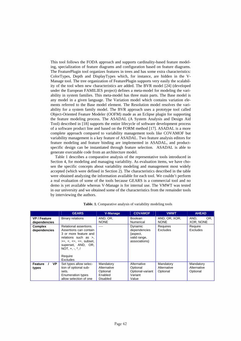
This tool follows the FODA approach and supports cardinality-based feature model-ing, specialization of feature diagrams and configuration based on feature diagrams. The FeaturePlugin tool organizes features in trees and has some extra characteristics: ColorTypes, Depth and DisplayTypes which, for instance, are hidden in the V-Manage tool. The tree organization of FeaturePlugin supports very easily the scalabil-ity of the tool when new characteristics are added. The BVR model [24] (developed under the European FAMILIES project) defines a meta-model for modeling the vari-ability in system families. This meta-model has three main parts. The Base model is any model in a given language. The Variation model which contains variation ele-ments referred to the Base model element. The Resolution model resolves the vari-ability for a system family model. The BVR approach uses a prototype tool called Object-Oriented Feature Modeler (OOFM) made as an Eclipse plugin for supporting the feature modeling process. The ASADAL (A System Analysis and Design Aid Tool) described in [18] supports the entire lifecycle of software development process of a software product line and based on the FORM method [17]. ASADAL is a more complete approach compared to variability management tools like COVAMOF but variability management is a key feature of ASADAL. Two feature analysis editors for feature modeling and feature binding are implemented in ASADAL, and product-specific design can be instantiated through feature selection. ASADAL is able to generate executable code from an architecture model.
Table 1 describes a comparative analysis of the representative tools introduced in Section 4, for modeling and managing variability. As evaluation items, we have cho-sen the specific concepts about variability modeling and management most widely accepted (which were defined in Section 2). The characteristics described in the table were obtained analyzing the information available for each tool. We couldn’t perform a real evaluation of some of the tools because GEARS is a commercial tool and no demo is yet available whereas V-Manage is for internal use. The VMWT was tested in our university and we obtained some of the characteristics from the remainder tools by interviewing the authors.
Table. 1. Comparative analysis of variability modeling tools
GEARS V-Manage COVAMOF VMWT AHEAD
VP / Feature
dependencies
Binary relations AND, OR, NONE
Boolean Numerical
AND, OR, XOR, NONE
AND, OR, XOR, NONE
Complex
dependencies
Relational assertions. Assertions can contain 3 or more feature and relations such as >, >=, <, <=, ==, subset, superset, AND, OR, NOT, +, -, *, / Require Excludes
---- Dynamic dependencies {aspect, valid range, associations}
Requires Excludes
Require Excludes
Feature / VP
types
Set types allow selec-tion of optional sub-sets. Enumeration types allow selection of one
Mandatory Alternative Optional Enabled Disabled
Alternative Optional Optional-variant Variant Value
Mandatory Alternative Optional
Mandatory Alternative Optional
Page 42
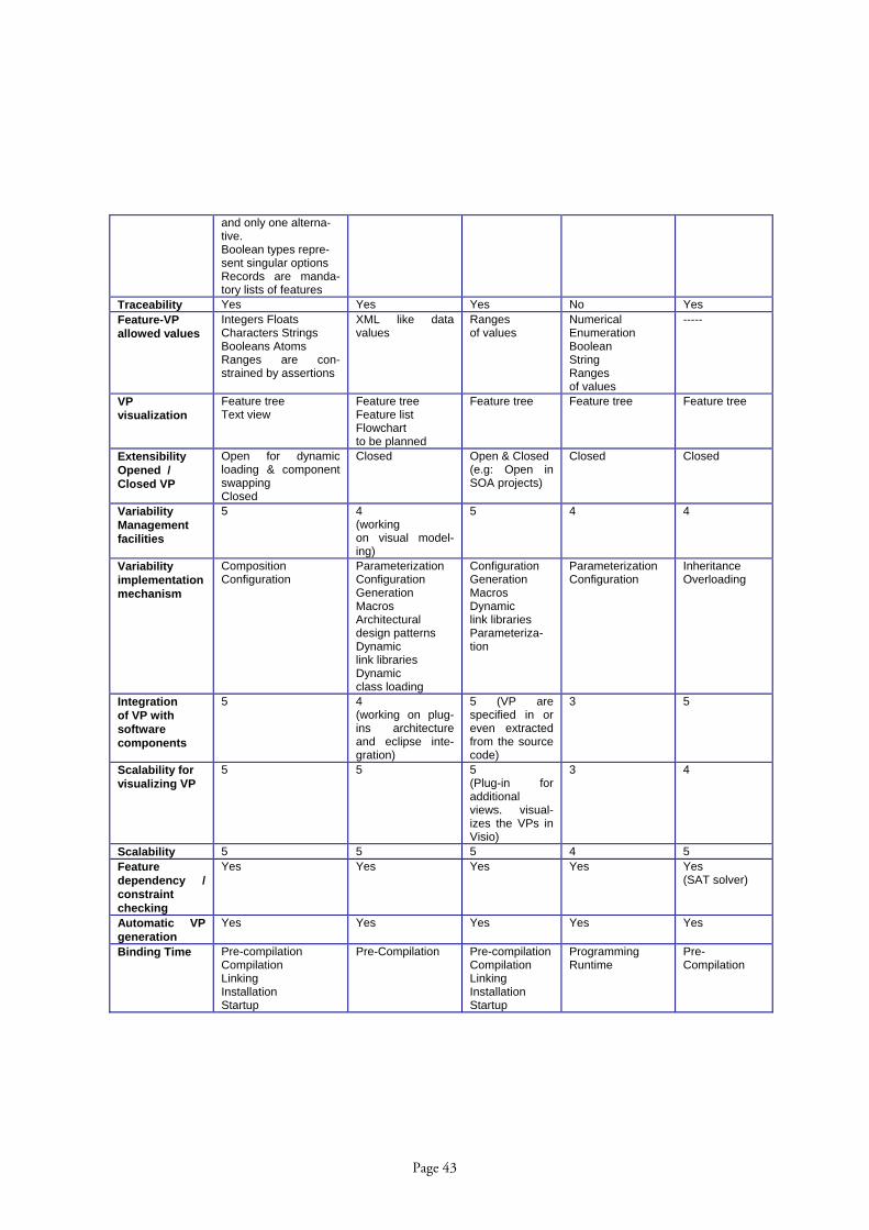
and only one alterna-tive. Boolean types repre-sent singular options Records are manda-tory lists of features
Traceability Yes Yes Yes No Yes
Feature-VP
allowed values
Integers Floats Characters Strings Booleans Atoms Ranges are con-strained by assertions
XML like data values
Ranges of values
Numerical Enumeration Boolean String Ranges of values
-----
VP
visualization
Feature tree Text view
Feature tree Feature list Flowchart to be planned
Feature tree Feature tree Feature tree
Extensibility
Opened /
Closed VP
Open for dynamic loading & component swapping Closed
Closed Open & Closed (e.g: Open in SOA projects)
Closed Closed
Variability
Management
facilities
5 4 (working on visual model-ing)
5 4 4
Variability
implementation
mechanism
Composition Configuration
Parameterization Configuration Generation Macros Architectural design patterns Dynamic link libraries Dynamic class loading
Configuration Generation Macros Dynamic link libraries Parameteriza-tion
Parameterization Configuration
Inheritance Overloading
Integration
of VP with
software
components
5 4 (working on plug-ins architecture and eclipse inte-gration)
5 (VP are specified in or even extracted from the source code)
3 5
Scalability for
visualizing VP
5 5 5 (Plug-in for additional views. visual-izes the VPs in Visio)
3 4
Scalability 5 5 5 4 5
Feature
dependency /
constraint
checking
Yes Yes Yes
Yes Yes (SAT solver)
Automatic VP
generation
Yes Yes Yes Yes Yes
Binding Time Pre-compilation Compilation Linking Installation Startup
Pre-Compilation
Pre-compilation Compilation Linking Installation Startup
Programming Runtime
Pre-Compilation
Page 43

Runtime Runtime
Statistical
analysis and
Reporting
Yes Yes Yes Variability and Project PDF documents
No
Product
derivation
Yes Yes Yes Partially Yes
Estimation
of the number
of products
Yes (Combinatory report-ing of estimated in-stances)
Yes No Yes Yes (SAT solver)
Phases of the
lifecycle
covered
Analysis Design Implementation
Requirements Design Implementation
Analysis Design Implementation
Design Implementation
Design Implementation
Tool approach Modeling Management
Modeling
Modeling Management
Configuration Modeling Management
Configuration Modeling
Development
approach
Specialization Compositional
Compositional Derivation
Compositional Generative
Specialization Compositional
Specialization Compositional Generative
Platform /
Technology
Java Standalone version with Eclipse and Vis-ual Studio
Java Ant XML Eclipse
MS Visual Studio.NET XML
PHP AJAX JavaScript
Java-Ant XML
5. Impact on Product Line Development
Today, we have many examples of successful products lines (e.g.: Celsius Tech Cummins, Salion, Market Maker, Thales Naval, HP, etc) in which multiple products are designed and built under strong time to market conditions. The Nokia product line an example of successful product line which comprises multiple mobile phones or-ganized around different families (e.g.: Nokia series 30, 60). A few examples of using the tools in real cases have been documented and the numbers of savings in terms of cost and effort have been reported. Some of the aforementioned tools have been tested both in academia and in industry. For instance, COVAMOF was used on the Intrada product family from Dacolian B.V., a small independent SME in The Nether-lands for intelligent traffic systems [28]. Engenio is a firm dedicated to high-performance disk storage systems with approximately 200 developers distributed across four locations. Around 80% of the code is common to the 82 products of the firm. The increasing demand for Engenio’s RAID storage server products led to the adoption of a product line approach and Gears was selected for this. Several success-ful results were obtained (see [14]). For instance, Engenio has experienced a 50% increase in development capacity. All these stories prove that software product lines constitute a successful approach for building software system families, and tools are strongly needed for managing the amount of variability required.
Page 44

6. Current Limits and Second-generation Tools
The aforementioned tools constitute an important help for product line engineer-ing. The lack of a unified approach for software variability leads to a certain number of tools with the same goal and similar characteristics, but with differences between them. There are some limitations of current tools as well as some issues that can be enhanced. For instance, the visualization of hundreds of variation points with their associated variants, in particular in industrial product lines, is a limitation of some of the existing tools, and new visualization facilities are welcome. As an example, we tested VMWT in two medium-size web projects and we observed that the tool needs better visualization capabilities when the number of variation points and variants scale up. Another issue, in particular for complex systems, is the need to handle com-plex dependencies. Some of the existing tools need to support more complex depend-encies for describing all the relationships and constraints for any type of software system. Also, the extensibility of the variability model for supporting runtime vari-ability (e.g.: adding variation points during the execution of the system) is a complex problem associated to the evolution of the system that could be alleviated by the us-age of plug-ins mechanisms in runtime. The integration of variability modeling tools with traditional software engineering tools seems quite interesting for software prod-uct line engineering. In particular, unless there is a serious effort by the variability tools providers to integrate these tools with software configuration management tools and integrate the variability management activities in the practical development proc-esses, the success of these tools will be in danger. The integration of variability tools with the configuration management community is an interesting issue to explore for configuration management purposes. Also, variability management tools could learn about the knowledge management community to incorporate more additional fea-tures. These and other capabilities seem to be interesting to be added and we believe a second-generation variability tools is a goal to pursuit. In this paper we have studied some representative tools for modeling and managing software variability in order to discover the needs for second-generation tools. Most of the tools analyzed share many common characteristics and most of them focus on specialization and composi-tional approaches. The estimation of the number of allowed products or right configu-rations is an interesting issue for the defining production plans and for cost estima-tion. The majority of the tools cover design and implementation phases of the soft-ware lifecycle. Finally, integrated derivation processes from feature models to prod-ucts are welcome to reduce the effort of configuration processes.
Acknowledgements
We thank to Charlie Krueger for his useful information about GEARS, which has been balanced between commercial and academic reasons; also Jason X. Mansell (ESI) who gave us many responses about V-manage. Many thanks to Marco Sinnema for providing useful information of COVAMOF-VS, and Salva Trujillo and Oscar Díaz who provide us the details of AHEAD TS in alive discussions
Page 45

References
1. Antkiewicz, M. and Czarnecki K. FeaturePlugin: Feature Modeling Plug-in for Eclipse, OOPSLA’04 Eclipse Technology eXchange (ETX) Workshop, 2004
2. Bass, L., Clements P. and Kazman, R. Software Architecture in Practice, Addison-Wesley, 2nd edition, (2003).
3. Batory, D., Sarvela, J.N. and Rauschmayer, A. Scaling Step-Wise Refinement. IEEE TSE 30(6) 355-371, (2004).
4. Bayer, J, Gerard, S., Haugen, Ø, Mansell, J., Møller-Pedersen, B., Oldevik, J., Tessier, P., Thibault, J.P. and Widen, T. Consolidated Product Line Variability Modeling, In Software Product Lines Research Issues in Engineering and Management, Springer-Verlag, Timo Käköla and Juan Carlos Dueñas (Eds), pp. (2006).
5. Becker, M. Mapping Variability’s onto Product Family Assets. Procs of the International Colloquium of the Sonderforschungberich 501, University of Kaisersalutern, Germany, (2003).
6. Bosch, J. Design and Use of Software Architectures, Addison-Wesley (2000). 7. Berg, K., Bishop, J. and Muthig, D. Tracing Software Product Line Variability – From Prob-
lem to Solution Space. Procs of the Annual Conference of the South African Institute of Computer Scientists and Information Technologists (SAICSIT), pp. 111-120 (2005).
8. Capilla, R. and Dueñas, J.C. Modelling Variability with Features in Distributed Architec-tures, Procs of Product Family Engineering (PFE), Springer-Verlag LNCS pp. 319-329, (2001).
9. Díaz, O., Trujillo, S. and Anfurrutia, F.I. Supporting Production Strategies as Refinements of the Production Process. Procs of 9th Software Product Line Conference (SPLC), Springer-Verlag LNCS 3714 pp.210-221, (2005).
10. Dobrica, L. and Niemelä, E. Using UML Notation Extensions to Model Variability in Product-line Architectures. International Workshop on Software Variability Management (SVM), ICSE’03, Portland, Oregon, USA pp. 8-13 (2003).
11. Fritsch, C., Lehn, A. and Strohm, T. Evaluating Variability Implementation Mechanisms. Procs of International Workshop on Product Line Engineering (PLEES’02), Technical Re-port at Fraunhofer IESE (No. 056.02/E) 59-64 (2002).
12. Gomaa, H. and Shin, M.E. Variability in Multiple-View Models of Software Product Lines. International Workshop on Software Variability Management (SVM), ICSE’03, Portland, Oregon, USA pp. 63-68 (2003).
13. Griss M. L., Favaro J., d’Alessandro M., Integrating Features Modeling with the RSEB. 5th International Conference on Software Reuse, IEEE Computer Society (1998)
14. Hetrick, W.A., Krueger, C.W. and Moore, J.G. Incremental Return on Incremental Invest-ment: Engenio’s Transition to Software Product Line Practice. Conference on Object Oriented Programming Systems Languages and Applications, Companion to the 21st ACM SIGPLAN conference on Object-oriented programming systems, lan-guages, and applications (OOPSLA), ACM pp. 798-804 (2006).
15. Jaring, M. and Bosch, J. Variability Dependencies in Product Family Engineering. 5th International Workshop on Product family Engineering (PFE), Springer-Verlag, LNCS 3014, pp. 81-97, (2004).
16. Kang K. C., Cohen S., Hess J. A., Novak W. E., Peterson A. S.. Featured-Oriented Domain Analysis (FODA) Feasibility Study. Technical Report, CMU/SEI-90-TR-21 ESD-90-TR-22, Software Engineering Institute, Carnegie Mellon University, Pittsburgh (1990).
17. Kang K. C., Kim, S., Lee, J., Kim, K., Shin, E., and Huh, M. FORM: A Feature-oriented Reuse Method with Domain Specific Software Architectures. Annals of Software Engineer-ing, Vol 5(1) pp. 143-168, Springer (1998).
Page 46
18. Kim, K., Kim, H., Ahn, M., Seo, M., Chang, Y. and Kang, K.C. ASADAL: A Tool System for Co-Development of Software and Test Environment based on Product Line Engineering. ICSE 2006, pp. 783-786, (2006).
19. Krueger, C. W. Software Mass Customization. BigLever Software Inc. Available at: http://www.biglever.com/extras/BigLeverMassCustomization.pdf, (2006).
20. Lee, K. and Kang, K.C. Feature Dependency Analysis for Product Line Component De-sign. 8th International Conference on Software Reuse (ICSR), Madrid, Springer-Verlag LNCS 3107, pp. 69-85, (2004).
21. Lee, Y., Yang, C., Zhu, C. and Zhao, W. An Approach to Managing Feature Dependencies for Product releasing in Software Product Lines. 9th International Conference on Software Reuse (ICSR), Turin, Italy, Springer-Verlag LNCS 4039, pp. 127-141, (2006).
22. Myllymäki, T. Variability Management in Software Product Lines. Technical Report 30. Institute of Software Systems, Tampere University of Technology (2002).
23. Robak, S. Feature Modeling Notations for System Families. International Workshop on Software Variability Management (SVM), ICSE’03, Portland, Oregon, USA pp. 58-62 (2003).
24. Shakari, P. and Møller-Pedersen, B. On the Implementation of a Tool for feature Modeling with a base Model Twist. Available at: http://www.himolde.no/nik06/articles/08-Shakari.pdf
25. Sinnema, M., Deelstra, S., Nijuis, J. And Bosch, J. COVAMOF: A Framework for Model-ing Variability in Software Product Families. Procs of 3rd International Software Product Line Conference (SPLC), Springer-Verlag LNCS 3154, pp. 197-213, (2004).
26. Sinnema, M., de Graaf, O. and Bosch, J. Tool Support for COVAMOF. Procs of the 2nd Groningen Workshop on Software Variability Management (SVMG), Groningen, The Neth-erlands, (2004).
27. Sinnema, M., Deelstra, S., Nijuis, J. And Bosch, J. Modeling Dependencies in Product Families with COVAMOF. Procs of 13th International Workshop on Engineering of Com-puter Based Systems (ECBS’06), pp. 299-307 (2006).
28. Sinnema, M., Deelstra, S., Nijuis, J. and Hoekstra, P. The COVAMOF Derivation Process, 9th International Conference on Software Reuse (ICSR), Turin, Italy, Springer-Verlag LNCS 4039, pp. 101-114, (2006).
29. Svahnberg, M., van Gurp, J. and Bosch, J. A Taxonomy of Variability Realization Tech-niques. Software Practice & Experience, vol 35(8), 705-754, (2005).
30. Tolvanen, J-P., Kelly, S. Defining Domain-Specific Modeling Languages to Automate Product Derivation: Collected Experiences, Proceedings of the 9th International Software Product Line Conference, H. Obbink and K. Pohl (Eds.) Springer-Verlag, LNCS 3714, pp. 198 – 209, (2005).
31. Trujillo, S., Batory, D. and Díaz O. Feature Refactoring a Multi-Representation Applica-tion into a Product Line. Procs of 5th International Conference on Generative Programming and Component Engineering, pp. 191-200 (2006).
32. van Gurp, J., Bosch, J. and Svahnberg, M. Managing Variability in Software Product Lines. Procs of IEEE/IFIP Conference on Software Architecture, WICSA 2001, Amsterdam, The Netherlands, IEEE CS, pp. 45-54 (2001).
33. van Ommering, R. van der Linden, F., Kramer, J. and Magee, J. The Koala Component Model for Consumer Electronics Software. IEEE Computer, pp. 78-85, (2000).
34. Oldevik, J. Solberg, A., Haugen, Ø., -Pedersen, B. Evaluation framework for Model-Driven Product Line Engineering tools, In Software Product Lines Research Issues in Engineering and Management, Springer-Verlag, Timo Käköla and Juan Carlos Dueñas (Eds), pp. (2006).
Page 47

Tool-Supported Multi-Level Language Evolution
Markus Pizka and Elmar Jurgens
Technische Universitat MunchenInstitut fur Informatik
Boltzmannstr. 3Germany – 85748 Garching
Abstract. Through their high degree of specialization, domain specificlanguages (DSLs) promise higher productivity and thus shorter develop-ment time and lower costs than general purpose programming languages.Since many domains are subject to continuous evolution, the associatedDSLs inevitably have to evolve too, to retain their value. However, thecontinuous evolution of a DSL itself can be very expensive, since itscompiler as well as existing words (i. e. programs) have to be adaptedaccording to the changes to a DSL’s specification. These maintenancecosts compromise the expected reduction of development costs and thuslimit the success of domain specific languages in practice.This paper proposes a concept and a tool for the evolutionary develop-ment of domain specific languages. It provides language evolution oper-ations that automate the adaptation of the compiler and existing DSLprograms according to changes to the DSL specification. This signifi-cantly reduces the cost of DSL maintenance and paves the ground forbottom-up development of domain specific languages.
1 Domain Specific Chances and Limitations
Albeit three decades of intense research and significant progress in research andpractice, the development and maintenance of software systems still constitutesa time-consuming, costly and risky endeavor. The reduction of software devel-opment and maintenance costs thus remains a research topic of paramount im-portance to software engineering. A basic idea behind many approaches thatattempt to reduce these costs is to increase the productivity of software devel-opers. One approach to raise productivity that has received increased attentionin recent years, are domain specific languages.
1.1 Productivity Through Specialization
A domain-specific language (DSL) is a programming language or executablespecification language that offers, through appropriate notations and abstrac-tions, expressive power focused on, and usually restricted to, a particular prob-lem domain [1]. Hence, the key characteristic of domain specific languages istheir specialization to a problem domain. This specialization allows them to of-fer language constructs and abstractions tailored to the class of problems from
Page 48

this domain. DSLs typically allow these problems to be described very directlyand concisely, requiring less developer effort than general purpose programminglanguages. DSLs thus have the potential to increase productivity and decreasecosts of software development. Particularly prominent examples for the benefitsof DSLs are found in the compiler construction field with specialized languagesand generators (amongst others) for hashing (e. g. gperf), scanners, and parsers.Tools for the interactive design of graphical user interfaces, the query languageSQL, interface definition languages like WSDL or modeling languages like MAT-LAB/Simulink add further examples for the benefits of DSLs, i. e. purpose-builtlanguages with powerful generators.
Besides reduced development time and cost, DSLs are a promising meanto decrease the maintenance cost of software because of the reduced code sizeand increased comprehensibility, both due to the higher expressiveness of DSLscompared to general-purpose languages. The decrease of maintenance costs isparticularly important since 60-80% of the costs of software are usually notdevoted to initial development but to maintenance [2–4].
However, DSLs only help to reduce overall maintenance costs, as long asthe costs for development and maintenance of the DSL itself can be amortized.If unanticipated changes to a domain require changes to the DSL definition,maintenance costs can be high, as noted in [5].
1.2 Limitations
Thus, the success of DSLs is clearly still limited to few niches. To the extent ofour own practical experiences and that of our commercial partners, the bulk ofcode that gets written, be it information systems in financial institutions or flightcontrol systems for commercial aircrafts, makes little use of DSLs. Languageslike Risla for Financial Products [5] are rare exceptions to the rule.
We state that there are at least three major reasons for this which we will ex-plain more precisely in the following paragraphs. First are the costs of designingand implementing DSLs. Second, the limited capabilities of one-step generationand third, the constant need to evolve DSLs.
The multi-level language evolution concept and tool-support presented inthis paper largely increases the applicability of DSLs by helping to overcomeexactly these three current core difficulties in DSL design and implementation.
2 Challenges in DSL Design and Maintenance
The goal of the concept and tool-set presented in this paper is to increase thelong-term applicability of DSLs by supporting an evolutionary and bottom-uporiented style for DSL design and implementation. The rationale for this ap-proach is the need to overcome three major obstacles that we detail in thefollowing paragraphs.
Page 49
2.1 DSLs Are Expensive to Build
Though DSLs promise substantial gains in productivity, the development ofDSLs itself is expensive and troublesome. [6] summarizes the difficulties of build-ing DSLs adequately as follows:
DSL development is hard, requiring both domain knowledge and lan-guage development expertise. Few people have both. Not surprisingly,the decision to develop a DSL is often postponed indefinitely, if con-sidered at all, and most DSLs never get beyond the application librarystage.
Clearly, one of the primary contributions of DSLs is enabling reuse, i. e. reuseof abstractions and reuse of the knowledge about how to implement these ab-straction in different contexts. As such, DSLs must cope with the same economicchallenges like any other reuse oriented approach [7]. Building reusable compo-nents requires a costly analysis of the domain and its variability followed byan even more expensive implementation of reusable components1. The costs ofplanning and building such generalized components are usually a multiple of thecosts of building a concrete solution to a particular problem [7]. Hence, buildingDSLs only pays-off after repeated successful use of the DSL. However, due to theconstant change of requirements and the execution environment [8], the futureuse of a DSL is uncertain and building DSLs is economically risky. Note, thatthis risk increases with the degree of specialization respectively the potentialbenefit.
Requirement 1 (Stepwise Bottom-Up Generalization)To reduce the uncertainty of the benefit of DSL design and implementation, DSLsshould be built in an incremental and bottom-up oriented manner instead of thecurrently predominant top-down and big-bang like approach. To support this styleof DSL development, means for the step-wise generalization of existing conceptsand solutions as needed are required.
If DSLs can be built by gradually abstracting and flexibilizing existing so-lutions (including DSLs) as needed, then the cost of building a DSL will neversignificantly exceed the costs of developing the desired new solution from scratch,but often provide immediate pay-offs. No effort has to be put into speculationabout future requirements and there is no need for risky in advance investmentinto flexibility that could possibly be needed in the future.
2.2 Generators are no Oracles
A DSL usually requires a generator that reads a word2 of the domain specificlanguage and produces a word in the desired target language. Program gen-erators for DSLs are nothing but program transformation systems providing a1 In case of DSLs represented through the domain language and a code generator.2 The term word is used as in formal language theory to denote strings that conform
to the language syntax.
Page 50
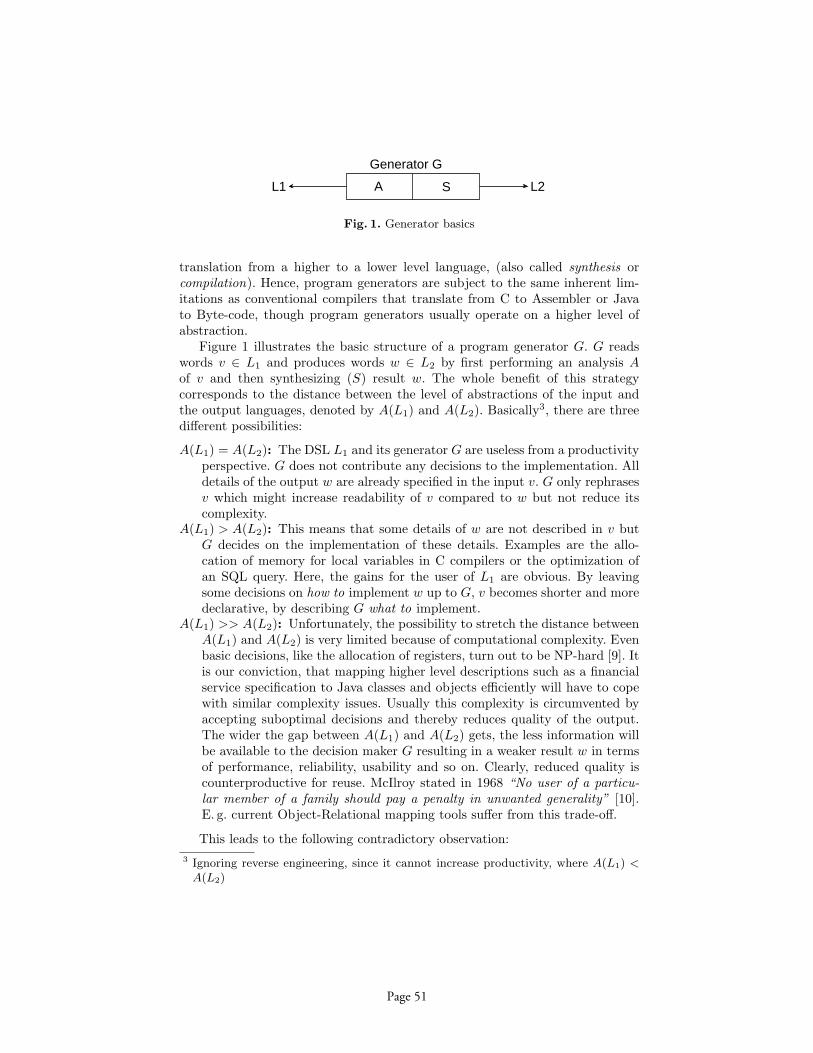
A S L2L1
Generator G
Fig. 1. Generator basics
translation from a higher to a lower level language, (also called synthesis orcompilation). Hence, program generators are subject to the same inherent lim-itations as conventional compilers that translate from C to Assembler or Javato Byte-code, though program generators usually operate on a higher level ofabstraction.
Figure 1 illustrates the basic structure of a program generator G. G readswords v ∈ L1 and produces words w ∈ L2 by first performing an analysis Aof v and then synthesizing (S) result w. The whole benefit of this strategycorresponds to the distance between the level of abstractions of the input andthe output languages, denoted by A(L1) and A(L2). Basically3, there are threedifferent possibilities:
A(L1) = A(L2): The DSL L1 and its generator G are useless from a productivityperspective. G does not contribute any decisions to the implementation. Alldetails of the output w are already specified in the input v. G only rephrasesv which might increase readability of v compared to w but not reduce itscomplexity.
A(L1) > A(L2): This means that some details of w are not described in v butG decides on the implementation of these details. Examples are the allo-cation of memory for local variables in C compilers or the optimization ofan SQL query. Here, the gains for the user of L1 are obvious. By leavingsome decisions on how to implement w up to G, v becomes shorter and moredeclarative, by describing G what to implement.
A(L1) >> A(L2): Unfortunately, the possibility to stretch the distance betweenA(L1) and A(L2) is very limited because of computational complexity. Evenbasic decisions, like the allocation of registers, turn out to be NP-hard [9]. Itis our conviction, that mapping higher level descriptions such as a financialservice specification to Java classes and objects efficiently will have to copewith similar complexity issues. Usually this complexity is circumvented byaccepting suboptimal decisions and thereby reduces quality of the output.The wider the gap between A(L1) and A(L2) gets, the less information willbe available to the decision maker G resulting in a weaker result w in termsof performance, reliability, usability and so on. Clearly, reduced quality iscounterproductive for reuse. McIlroy stated in 1968 “No user of a particu-lar member of a family should pay a penalty in unwanted generality” [10].E. g. current Object-Relational mapping tools suffer from this trade-off.
This leads to the following contradictory observation:3 Ignoring reverse engineering, since it cannot increase productivity, where A(L1) <
A(L2)
Page 51
1. The benefit that can be gained from a single generator is inherently andseverely limited. We are convinced that there will not be a single flexibleDSL for some high-level business domain with a generator that maps it tohigh-quality Java code.
2. To gain a significant advantage from a DSL, the gap between the level ofabstractions of the input and the output has to be wide (see A(L1) > A(L2)).
The concept and tool-set presented in this paper aims at solving this conceptby fulfilling the following requirement.
Requirement 2 (DSL Layering)The design and implementation of a DSL should not be limited to a one-stepcompilation but support layers of DSLs and a staged generation process withadditional user input at each stage.
Note, that staging further increases the complexity and costs of building andmaintaining the DSL as discussed in 2.1 because changes on one stage mightaffect other stages, too. Again, ruling this complexity requires a tool-set thataids in gradually adapting the DSL hierarchy as needed (see requirement 1).
2.3 Language and Word Evolution
While building a DSL is costly, building layered DSLs is even more expensiveand maintaining a single or even layered DSL is even worse because nothing ismore constant than change entailing a constant need for evolution [8].
The design and implementation of a DSL trivially depends on the require-ments of the domain. With the exception of DSLs that model a technical domain,such as regular expressions or SQL, the requirements are directly connected withthe business processes in this domain. Unfortunately, business processes are veryvolatile [11], simply because business process agility is the mean to achieve com-petitive advantages.
This poses a serious difficulty for DSLs. On the one hand, a DSL should behigh-level or in other words as close to the business processes as possible in orderto provide increased productivity compared to a general purpose language. Onthe other hand, the tighter the DSL is connected with the business processes,the more fragile it gets and the more often it will have to be changed, which inturn reduces the benefits of possible reuse.
A non-trivial change to an existing DSL L leading to a new DSL version L′
requires the following three major steps:
1. Change of the definition of L – its syntax and semantics.2. Adaption of all tools processing L; at least the corresponding compiler or
generator but possibly also syntax aware editors (e. g. highlighting), debug-ger, etc.
3. Transformation of all already existing words (programs) w ∈ L into languageL′.
Page 52
As an alternative to step 3, one could also maintain older versions of DSLs sothat words in older versions of the language could still be used and changedindependently of newer versions of the language. However, this would create acomplicated configuration management problem and in addition to this, users ofolder versions of the language could not benefit from any advantages of newerversions and new tools. In practice, this drawbacks forces users to migrate theirwords to the new version.
Hence, most DSLs will have to evolve over time, including the tools thatprocess these DSLs and words written in these languages. Without adequatetool-support, DSL evolution is a complex, time-consuming, and error-prone taskthat severely hampers the long-term success of a DSL.
Requirement 3 (Automated Co-Evolution) DSL maintenance is inevitablefor most realistic domains and requires adequate tool support. The transformationof existing words and the adaptation of language processing tools according tochanges of the language has to be automated as far as possible.
Note that this requirement complements requirement 1 because the tool-supported co-evolution of language, tools and words is a contribution to stepwisebottom-up generalization as formulated in requirement 1.
3 Related Work
The work presented in this paper combines DSLs [1] and generative programming[12] with elements of program transformation [13] and compiler construction, aswell as software evolution [8]. Within this general context, the evolution con-cept has strong relations with Grammar Engineering and language evolution asdescribed in the following paragraphs.
3.1 Grammar Engineering
In [14], Klint, Lammel and Verhoef argue that although grammars and relatedformalisms play a pervasive role in software systems, their engineering is insuffi-ciently understood. They propose an agenda that is meant to promote researchon Grammarware and state research challenges that need to be addressed inorder to improve the development of grammars and dependent software.
One of these challenges is the development of a framework for grammar trans-formations and the co-evolution of grammar-dependent software. The GrammarEvolution Language proposed in this paper offers such grammar transforma-tion operations, and the automatic generation of compilers from DSL definitionswith static validation of path expressions aims at the desired co-evolution of oneimportant instance of grammar-dependent software, namely the compiler.
In [15], Lammel proposes a comprehensive suite of grammar transformationoperations for the incremental adaptation of context free grammars. The pro-posed operations are based on sound, formal preservation properties that allow
Page 53
to reason about the relationship between grammars before and after transforma-tion. [16] and [17] present systems that implemented these evolution operationsto incrementally transform LLL and SDF grammars.
Lammel’s grammar adaptation operations inspired the design of the Gram-mar Evolution Language used in our approach as a mean to automate languageevolution. However, this paper focuses primarily on the coupled evolution ofgrammars and words of the language described by these grammars. Comparedto the operations suggested by Lammel, the Grammar Evolution Language sacri-fices the formal basis to allow for simpler coupled evolution operations. It wouldbe desirable to combine the coupled evolution capabilities proposed in this paperwith the formal preservation properties proposed by Lammel in future versionsof our tool Lever.
3.2 Evolution of Language Specifications
TransformGen is a system that generates converters that adapt programs ac-cording to changes of the language specification [18, 19]. While TransformGenautomatically produces converters for local4 changes, non-local transformationsmust be specified manually. Furthermore, non-local transformations cannot bereused between recurring evolution operations.
TransformGen only targets the adaptation of words but does not take lan-guage processing tools into account. The tool Lever presented in this paper goesone step further by semi-automating the adaptation of compilers, too. Moreover,Lever supports reuse of coupled transformations.
3.3 Schema Evolution in Object Oriented Databases
Regarding a data base schema as a language and the information contained in adata base as the words of this language allows to relate schema evolution withprogram transformation. Co-evolution of language and words is of predominantimportance to this field and studied in various works.
In [20], Banerjee proposes a methodology for the development of schemaevolution frameworks for object oriented databases (OODB) that was used inthe ORION OODB system. The methodology suggests invariants for consis-tent database schemas and evolution primitives for incremental changes to thedatabase. The evolution primitives perform coupled updates of both the schemaand the objects in the database. Similar schema invariants and update primi-tives were proposed in [21] for GemStone OODB. The DSL Dictionary invariantsthat we use in our approach were inspired by these ideas. In [22], Ferrandina de-scribes the schema evolution approach used in the O2 OODB. In contrast to thecoupled evolution primitives of ORION, it performs schema and data updatesseparately. While a declarative language is used for schema updates, migrationof objects to new schema versions is based on user-defined conversion functions.Through this separation, O2 is able to support global evolution operations. The4 Local transformations are restricted to the boundary of a grammar production.
Page 54
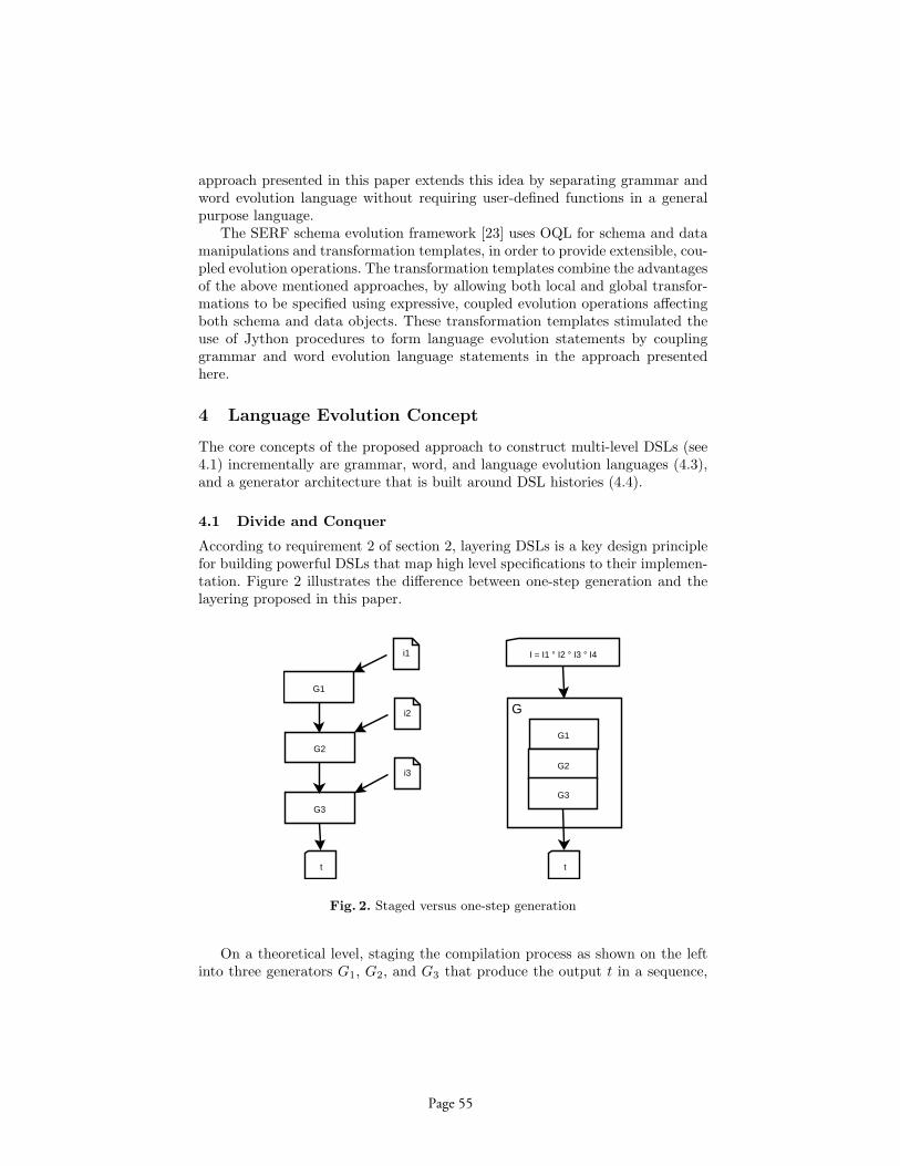
approach presented in this paper extends this idea by separating grammar andword evolution language without requiring user-defined functions in a generalpurpose language.
The SERF schema evolution framework [23] uses OQL for schema and datamanipulations and transformation templates, in order to provide extensible, cou-pled evolution operations. The transformation templates combine the advantagesof the above mentioned approaches, by allowing both local and global transfor-mations to be specified using expressive, coupled evolution operations affectingboth schema and data objects. These transformation templates stimulated theuse of Jython procedures to form language evolution statements by couplinggrammar and word evolution language statements in the approach presentedhere.
4 Language Evolution Concept
The core concepts of the proposed approach to construct multi-level DSLs (see4.1) incrementally are grammar, word, and language evolution languages (4.3),and a generator architecture that is built around DSL histories (4.4).
4.1 Divide and Conquer
According to requirement 2 of section 2, layering DSLs is a key design principlefor building powerful DSLs that map high level specifications to their implemen-tation. Figure 2 illustrates the difference between one-step generation and thelayering proposed in this paper.
G1
G2
G3
t
i1
i2
i3
G1
G2
G3
t
G
I = I1 ° I2 ° I3 ° I4
Fig. 2. Staged versus one-step generation
On a theoretical level, staging the compilation process as shown on the leftinto three generators G1, G2, and G3 that produce the output t in a sequence,
Page 55

seems identical with one-step generation of a composed generator G as shownon the right hand side; with the technical exception that inputs i1, i2 and i3 arenot fed into the generation process at once but at the beginning of each stage.In fact, the concatenation of the various inputs i = i1 ◦ i2 ◦ i3 could be regardedas a word of the language I that results from concatenating the input languagesI1, I2, and I3.
However, there are strong differences between the staged or the one-stepgeneration model when it comes to the implementation of the DSL. Note, thatnot only the input fragments i2 and i3 depend on i1 respectively i2 ◦ i1 butalso every language In depends on all inputs previous to stage n. Technicallyspeaking, In corresponds with the information needed by Gn to further drive withthe generation process in the situation created by i0, . . . , in1 . Now, specifying theunified language I of all possible input sequences would theoretically be possiblebut technically impractical. It would yield a undesirable DSL with numeroussemantical conditions and exceptions allowing and restricting the use of languageelements within a word of the language depending on arbitrary prefixes of theword.
In addition to the improved structuring of DSL, the staged model also indi-cates a feasible way of implementing complex generation process by dividing thetask into separate steps with individual inputs at those points where it is needed.Though this might seem surprising for DSL design and implementation, this isexactly the strategy that system level software uses successfully to map high-level applications to system-level representations for execution. E. g. the C++source code i1 gets compiled with the C++ compiler G1. The link-loader G2
further sets the memory layout according to whether the user wants to executethe code as a stand-alone application or a shared library as specified in i2. Theoperating system kernel G3 then maps the results of these steps to main memorypages, CPU cycles, and so on according to the priorities of the user (i3). Imaginethe same process without staging. It would surely be possible but either hard tocomprehend or less flexible.
4.2 Generator Maintenance By Transformation
Maintaining such a sequence of dependent generators is highly complex by itselfand only practical with adequate tool-support. For example, if the top level DSLI1 must be changed to accommodate a new feature, there is a high probabilitythat the output of G1 changes too, entailing the need for changing I2, G2, andso on. All of these changes of languages (In) and programs (Gn) can themselvesbe treated as language and program transformations. Hence, the evident tool tomaintain a staged DSL is itself a DSL for the domain of DSL manipulation.
The crucial element of this overall architecture is the top-level language evo-lution language and the meta-level generator H. Our tool called Lever5 presentedin section 5 implements significant parts of such a meta-level generator basedon grammar and word evolution languages.
5 Language evolver.
Page 56
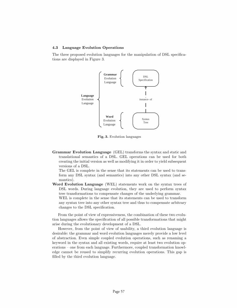
4.3 Language Evolution Operations
The three proposed evolution languages for the manipulation of DSL specifica-tions are displayed in Figure 3.
DSL Specification
Syntax Tree
instance- of
Grammar Evolution Language
Word Evolution Language
Language Evolution Language
Fig. 3. Evolution languages
Grammar Evolution Language (GEL) transforms the syntax and static andtranslational semantics of a DSL. GEL operations can be used for bothcreating the initial version as well as modifying it in order to yield subsequentversions of a DSL.The GEL is complete in the sense that its statements can be used to trans-form any DSL syntax (and semantics) into any other DSL syntax (and se-mantics).
Word Evolution Language (WEL) statements work on the syntax trees ofDSL words. During language evolution, they are used to perform syntaxtree transformations to compensate changes of the underlying grammar.WEL is complete in the sense that its statements can be used to transformany syntax tree into any other syntax tree and thus to compensate arbitrarychanges to the DSL specification.
From the point of view of expressiveness, the combination of these two evolu-tion languages allows the specification of all possible transformations that mightarise during the evolutionary development of a DSL.
However, from the point of view of usability, a third evolution language isdesirable: the grammar and word evolution languages merely provide a low levelof abstraction. Even simple coupled evolution operations, such as renaming akeyword in the syntax and all existing words, require at least two evolution op-erations – one from each language. Furthermore, coupled transformation knowl-edge cannot be reused to simplify recurring evolution operations. This gap isfilled by the third evolution language.
Page 57

Language Evolution Language (LEL) statements perform coupled evolutionof both the grammar and the syntax tree. They provide a higher level of ab-straction to users and enable reuse of coupled transformation knowledge.LEL builds on the GEL and WEL to implement its transformations.
LEL can be conceived as a procedure mechanism that uses GEL and WELstatements in the bodies of LEL procedures.
4.4 Evolution Architecture
Figure 4 shows the central components of the architecture of our language evo-lution tool Lever.
All evolution operations applied during the construction and evolution of aDSL are stored in the DSL History. The DSL History thus contains transforma-tion information that specifies the delta between consecutive versions of a DSL.This transformation information is used to automatically adapt both the DSLcompiler and existing DSL words to conform to the latest language version.
Lever
DSL History
DSL Word
instantiation
parsing
DSL Specification
Syntax Tree
semantic processing
Target Code
generation
instance- of
Fig. 4. Lever architecture
DSL History contains evolution operations that define specifications for allversions of a DSL: The first evolution operations create the DSL specificationfor the initial version of a DSL. Subsequent evolution operations transformthe DSL specification to yield later DSL versions.
DSL Specification is a comprehensive, declarative specification of the syntaxand static and translational semantics of a single version of the DSL. It isexplicitly available at runtime and drives the compilation process.
Syntax Tree is the in-memory representation of DSL words. It is an abstractsyntax tree that is decorated with concrete syntax and semantic attributes.
Page 58
DSL Word is the input for the compilation process. DSL words are versionedto allow the identification of the DSL version in which the word was written.
Target Code is the result of the compilation process.
Compiling Words of Arbitrary Versions The information contained in theDSL history allows to translate DSL words written in any version of the DSL.During the compilation process, the following steps are performed:
1. Identification of the DSL word’s language version.2. Execution of the evolution operations from the DSL history in order to create
a DSL specification in the corresponding language version.3. Generation of a parser from the information in the DSL specification. The
parser is then used to instantiate the syntax tree from the DSL word.4. Transformation of DSL specification and syntax tree to the latest language
version. Versions of the DSL dictionary and the syntax tree are comparedwith this latest DSL version. If needed, the DSL history is used to transformboth the DSL specification and the syntax tree to the latest version.
5. Semantic processing: according to the DSL semantics contained in the DSLspecification, target code for the syntax tree is computed and written to theoutput.
5 Implementation: Lever
The proposed evolution operations and evolution architecture is implementedprototypically in our tool Lever. Lever is implemented in Java. Evolution lan-guages are implemented as internal DSLs in Jython [24], the Scannerless Gener-alized LR parser (SGLR) [25] is used for parsing and the velocity template engineis used for code generation.
5.1 DSL Specification Formalism
Lever uses an object oriented interpretation of attribute grammars6[26] as speci-fication formalism for both syntax and semantics of a DSL. In Lever, DSL speci-fications are called DSL Dictionaries, since they define the syntax and semanticsof every word a language comprises.
In DSL dictionaries, semantic rules specify how target code gets generatedfrom the data contained in the syntax tree. In order to cleanly separate targetcode fragments, code generation logic and syntax tree access from one another,DSL dictionaries use code generation templates as semantic rules. Access to thesyntax tree from within code generation templates runs via XPath [27] expres-sions.
Every access to the syntax tree from within a semantic rule introduces a de-pendency between the rule and the syntax tree. Language evolution operations6 Context free grammars extended with semantic attributes and rules for their com-
putation.
Page 59

may change the shape of the syntax tree and thus potentially break these de-pendencies. In order to support DSL architects, Lever can statically validate allXPath expressions against the DSL dictionary and thus detect broken depen-dencies during language evolution.
5.2 Evolution Operations in Lever
The Grammar Evolution Language (GEL) comprises statements to declare non-terminals, to create, rename and delete productions, to add, modify and remove(literal, terminal or nonterminal) production components and (inherited or syn-thesized) attribute declarations, to set semantic rules, to change the order ofproduction components and to influence priorities and associativity of produc-tions. Every GEL statement operates on a single DSL Dictionary element.
The Word Evolution Language (WEL) comprises statements that use XPathexpressions to select, insert, update and remove nodes from the syntax tree. Fur-thermore, it contains statements to declaratively construct syntax tree fragmentsand change the dictionary element a syntax tree node instantiates.
The Language Evolution Language (LEL) comprises statements for recurringcoupled evolution operations, such as the introduction or removal of literal orterminal symbols, the encapsulation or in-lining of production components orthe renaming of productions or literals (i.e. keywords).
5.3 Limitations
The current version of Lever only automates the adaptation of the DSL compiler.Additional tools, such as a debugger, pretty printer or syntax aware editor stillhave to be maintained manually.
Furthermore, Lever currently only targets textual DSLs. However, it is ourconviction, that the stated problems also hold for visual DSLs and we believethat the concepts this paper proposes can also be applied to them.
6 Case Study: Catalog Description Language
As a proof of concept, Lever was applied to develop a specification language forproduct catalog management systems in an evolutionary way. The results showthe feasibility of the proposed approach to DSL development.
Due to space constraints, this case study only demonstrates language evolu-tion in a single stage scenario. On a conceptual level, this can be justified, sincethe conceptual distance between the DSL and the target code framework is smallenough to allow for generation of high-quality Java code.
6.1 Domain
Product catalogs are collections of structured product documents. Each docu-ment belongs to a product family. Typically, all documents within a product
Page 60

family share the same structure, whereas different families have different docu-ment structures.
Catalog management systems are used to create, manage and publish productcatalogs. This comprises the creation, manipulation and deletion of documentsby users, and the persistence and export of catalog data to different media.Catalog management systems are data-centric. Thus, solution domain artifactsthat implement editors, display forms, persistence and data export depend onthe structure of the documents the implemented catalog comprises. Implement-ing each artifact by hand—for every single document structure contained in acatalog—is tedious, error prone and costly.
The goal of the Catalog Description Language (CDL) is to provide a declar-ative specification language for product catalogs, from which these structure-dependent artifacts can be generated. This increases the level of abstraction ofcatalog management system development, by using generation to replace stereo-type implementation activities.
Target System The Catalog management systems generated from CDL speci-fications comprise two types of code: generic framework code, which implementsfunctionality common to all catalog management systems, and catalog specificcode, which gets generated from CDL specifications.
As suggested by the Generation Gap pattern [28], inheritance is used toseparate generic framework code (which resides in base classes) from catalogspecific, generated code (which resides in generated subclasses).
Fig. 5. Framework architecture
Page 61
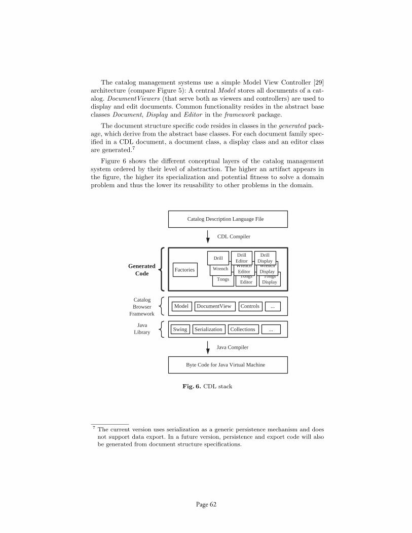
The catalog management systems use a simple Model View Controller [29]architecture (compare Figure 5): A central Model stores all documents of a cat-alog. DocumentViewers (that serve both as viewers and controllers) are used todisplay and edit documents. Common functionality resides in the abstract baseclasses Document, Display and Editor in the framework package.
The document structure specific code resides in classes in the generated pack-age, which derive from the abstract base classes. For each document family spec-ified in a CDL document, a document class, a display class and an editor classare generated.7
Figure 6 shows the different conceptual layers of the catalog managementsystem ordered by their level of abstraction. The higher an artifact appears inthe figure, the higher its specialization and potential fitness to solve a domainproblem and thus the lower its reusability to other problems in the domain.
Factories
Tongs Tongs Editor
Tongs Display
Wrench Wrench Editor
Wrench Display
Drill Drill
Editor Drill
Display
Swing Serialization Collections ...
Model DocumentView Controls ...
Generated Code
Catalog Browser
Framework
Java Library
Byte Code for Java Virtual Machine
Catalog Description Language File
CDL Compiler
Java Compiler
Fig. 6. CDL stack
7 The current version uses serialization as a generic persistence mechanism and doesnot support data export. In a future version, persistence and export code will alsobe generated from document structure specifications.
Page 62

Initial Language Version Listing 1.1 shows an exemplary specification8 fora tool catalog written in the initial version of CDL. The file specifies documentstructures for two product families: Wrenches consist of a single multi-line textfield Description, whereas Drills comprise one single-line text field Headline andtwo multi-line text fields Description and Shipment. The captions depict fieldlabels displayed in editor forms.
Due to space constraints, the complete specification of CDL and the evolutionoperations applied during its evolution have been omitted. Refer to [30] and [31]for a complete reference of the implementation and evolution of CDL.
1 vers ion 12 Wrench {3 mul t i l i n e Descr ipt caption ” Desc r ip t i on ” ;4 }
6 Dr i l l {7 s i n g l e l i n e Headl ine caption ”Family ” ;8 mul t i l i n e Descr ipt caption ” Desc r ip t i on ” ;9 mul t i l i n e Shipment caption ”Shipment In fo ” ;
10 }
Listing 1.1. CDL file in version 1
6.2 Evolving the Language
As is typical for incremental development, the first language version only com-prises a small set of core language elements. Instead of designing the completelanguage up-front, we will grow it in small steps. This saves us from the effortand cost of performing a domain and variability analysis for our DSL. Further-more, as we employ the first version of CDL to create catalog specifications, ourunderstanding of the domain grows and we get feedback on our language design.Based on this feedback, we can make founded decisions on how to evolve thelanguage.
In the following, we present two exemplary evolution steps: A relatively sim-ple transformation that changes the concrete syntax, and a more complex trans-formation that restructures the language in a non-local way.
Local transformation As a first change, we decide to make the concrete syntaxof CDL more expressive, by adding the keywords catalog, document and fieldand encapsulating the documents of a catalog in curly braces. Since this changeonly affects the concrete syntax of our language and leaves its abstract syntaxunchanged, no semantic rules have to be updated.
Listing 1.2 depicts the required evolution operations. Line 2 contains a Lan-guage Evolution Language statement that inserts the keyword catalog into the8 simplified due to space constraints
Page 63
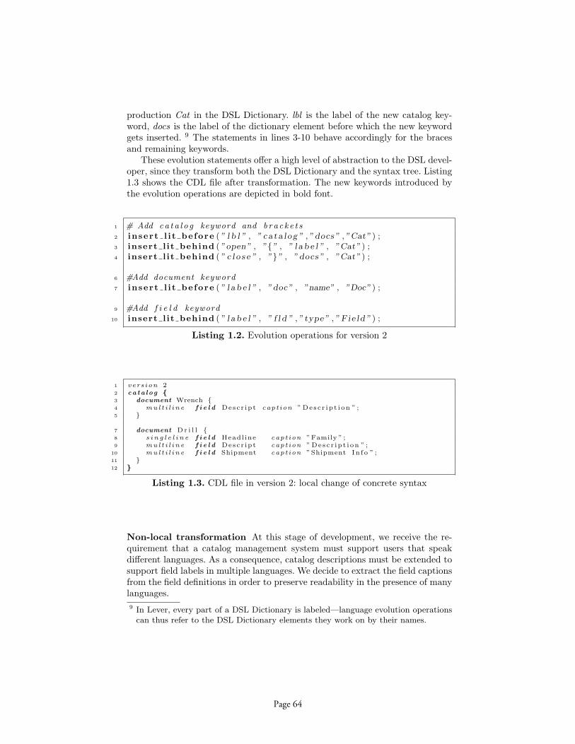
production Cat in the DSL Dictionary. lbl is the label of the new catalog key-word, docs is the label of the dictionary element before which the new keywordgets inserted. 9 The statements in lines 3-10 behave accordingly for the bracesand remaining keywords.
These evolution statements offer a high level of abstraction to the DSL devel-oper, since they transform both the DSL Dictionary and the syntax tree. Listing1.3 shows the CDL file after transformation. The new keywords introduced bythe evolution operations are depicted in bold font.
1 # Add ca t a l o g keyword and b ra c k e t s2 insert l i t before ( ” l b l ” , ” ca ta l og ” , ”docs ” , ”Cat” ) ;3 insert l it behind ( ”open” , ”{” , ” l a b e l ” , ”Cat” ) ;4 insert l it behind ( ” c l o s e ” , ”}” , ”docs ” , ”Cat” ) ;
6 #Add document keyword7 insert l i t before ( ” l a b e l ” , ”doc” , ”name” , ”Doc” ) ;
9 #Add f i e l d keyword10 insert l it behind ( ” l a b e l ” , ” f l d ” , ” type” , ” F i e ld ” ) ;
Listing 1.2. Evolution operations for version 2
1 vers ion 22 ca ta l o g {3 document Wrench {4 mul t i l i n e f i e l d Descr ipt caption ” Desc r ip t i on ” ;5 }
7 document Dr i l l {8 s i n g l e l i n e f i e l d Headl ine caption ”Family ” ;9 mul t i l i n e f i e l d Descr ipt caption ” Desc r ip t i on ” ;
10 mul t i l i n e f i e l d Shipment caption ”Shipment In fo ” ;11 }12 }
Listing 1.3. CDL file in version 2: local change of concrete syntax
Non-local transformation At this stage of development, we receive the re-quirement that a catalog management system must support users that speakdifferent languages. As a consequence, catalog descriptions must be extended tosupport field labels in multiple languages. We decide to extract the field captionsfrom the field definitions in order to preserve readability in the presence of manylanguages.9 In Lever, every part of a DSL Dictionary is labeled—language evolution operations
can thus refer to the DSL Dictionary elements they work on by their names.
Page 64

Listing 1.4 shows the CDL file after transformation. Lines 11-19 have beencreated by the evolution operations. Now that the labels have been extracted intoa captions region, further captions regions can be added for additional languages.
This evolution scenario is an example for a non-local restructuring. It cannotbe specified completely using high-level Language Evolution Language State-ments alone. Rather, statements from the low level grammar and word evolutionlanguages have been used to perform this evolution step. 10
1 vers ion 32 ca ta log {3 document Wrench {4 mul t i l i n e f i e l d Descr ipt ;5 }
7 document Dr i l l {8 s i n g l e l i n e f i e l d Headl ine ;9 mul t i l i n e f i e l d Descr ipt ;
10 mul t i l i n e f i e l d Shipment ;11 }
13 capt ions english {14 Wrench {15 Descript ”Description”;16 }
18 Dril l {19 Headline ”Family”;20 Descript ”Description”;21 Shipment ”Shipment Info ”;22 }23 }24 }
Listing 1.4. CDL file in version 3: non-local restructuring
7 Conclusion
DSLs are a promising approach to increase the productivity of software develop-ment through raising the level of abstraction and providing powerful generativetechniques. However, DSLs are expensive to build and even more expensive tomaintain. The concepts and implementation techniques presented in this paperallow a new style of DSL development and maintenance by incremental step-wiseevolution. This strategy renders the critical task of domain analysis less time-consuming and critical and significantly reduces the costs of changing a DSLby
1. automatically transforming all existing words in previous versions of the DSLand
10 The evolution script comprises about 20 evolution operations and has been left outof this paper for brevity.
Page 65

2. providing prototypical tool-support for the adaptation of the DSL compiler.
As shown with the exemplary product catalog description language, DSL archi-tects are enabled to introduce flexibility into the DSL as needed at any time. Thekey to this flexibility is the transformation tool Lever (language evolver) that it-self implements a powerful DSL for grammar, word, and coupled transformationfor the consistent manipulation of DSLs.
As shown in this paper, a tool like Lever contributes to the construction ofmore powerful DSLs that span several levels of abstractions because this canonly be done realistically by structuring the compilation process into a sequenceof generation steps with a corresponding set of DSLs. Building and maintainingsuch a sequence of DSLs without tool supported and coupled transformation ofgrammars and words seems highly impractical.
Clearly, this work leaves room for interesting future work. One open questionis how to further automate the adaption of the compiler and other languageprocessing tools according to chances of the language. Another question that wewill further investigate in the future is the actual construction of realisticallyapplicable multi-level DSLs with the tool Lever implemented as part of the workpresented in this paper.
References
1. van Deursen, A., Klint, P., Visser, J.: Domain-specific languages: An annotatedbibliography. SIGPLAN Notices 35(6) (2000) 26–36
2. Lientz, B.P., Bennet, P., Swanson, E.B., Burton, E.: Software Maitenance Man-agement. Addison Wesley, Reading (1980)
3. STSC: Software Reengineering Assessment Handbook v3.0. Technical report,STSC, U.S. Department of Defense (March 1997)
4. Pigoski, T.M.: Practical Software Maintenance. Wiley Computer Publishing (1996)5. Deursen, A., Klint, P.: Little languages: little maintenance? Technical report,
Amsterdam, The Netherlands (1997)6. Mernik, M., Heering, J., Sloane, A.: When and how to develop domain-specific
languages. Technical Report SEN-E0517, CWI (December 2005)7. Stutzle, R.: Wiederverwendung ohne Mythos: Empirisch fundierte Leitlinien fur
die Entwicklung wiederverwendbarer Software. PhD thesis, Technische UniversitatMunchen (April 2002) (Engl.: Reuse without Myth).
8. Lehman, M., Ramil, J.F., Wernick, P.D., Perry, D.E., Tursky, W.M.: Metrics andlaws of software evolution - the nineties view (1997)
9. Chaitin, G.: Register allocation and spilling via graph coloring. SIGPLAN Not.39(4) (2004) 66–74
10. McIlroy, M.: Mass produced software components. In Naur, P., Randell, B., eds.:Software Engineering, Garmisch, Germany, NATO Science Committee (October1968) 138–155
11. Panas, T., Lowe, W., Asmann, U.: Towards the unified recovery architecture forreverse engineering. In: SERP’03. Volume 1., Las Vegas, NV, CSREA Press (June2003) 854–860
12. Eisenecker, U.W., Czarnecki, K.: Generative Programmierung. Addison-Wesley,Munchen (2002)
Page 66

13. Visser, E.: A survey of strategies in program transformation systems. ElectronicNotes in Theoretical Computer Science 57 (2001)
14. Klint, P., Lammel, R., Verhoef, C.: Toward an engineering discipline for grammar-ware. ACM Trans. Softw. Eng. Methodol. 14(3) (2005) 331–380
15. Lammel, R.: Grammar Adaptation. In: Proc. Formal Methods Europe (FME)2001. Volume 2021 of LNCS., Springer-Verlag (2001) 550–570
16. Lammel, R., Wachsmuth, G.: Transformation of SDF syntax definitions in theASF+SDF Meta-Environment. In: Proc. of the 1st Workshop on Language De-scriptions, Tools and Applications (LDTA’01), publisher =. (April 2001)
17. Kort, J., Lammel, R.: The grammar deployment kit - system demonstration.In: Proceedings of the Second Workshop on Language Descriptions, Tools andApplications (LDTA’02). Volume 65 of ENTCS., Elsevier Science (2002)
18. Staudt, B.J., Krueger, C.W., Garlan, D.: A structural approach to the maintenanceof structure-oriented environments. In: SDE 2: Proc. of the 2nd software engineer-ing symposium on Practical software development environments, New York, NY,USA, ACM Press (1987) 160–170
19. Garlan, D., Krueger, C.W., Lerner, B.S.: Transformgen: automating the main-tenance of structure-oriented environments. ACM Trans. Program. Lang. Syst.16(3) (1994)
20. Banerjee, J., Kim, W., Kim, H.J., Korth, H.F.: Semantics and implementationof schema evolution in object-oriented databases. In: SIGMOD ’87: internationalconference on Management of data, New York, NY, USA, ACM Press (1987) 311–322
21. Penney, D.J., Stein, J.: Class modification in the gemstone object-oriented dbms.In: OOPSLA ’87, New York, NY, USA, ACM Press (1987) 111–117
22. Ferrandina, F., Meyer, T., Zicari, R., Ferran, G., Madec, J.: Schema and databaseevolution in the O2 object database system. In: Proc. of the 21th Intern. Conf. onVery Large Data Bases, San Francisco, CA, USA, Morgan Kaufmann PublishersInc. (1995) 170–181
23. Claypool, K.T., Jin, J., Rundensteiner, E.A.: Serf: schema evolution through anextensible, re-usable and flexible framework. In: CIKM ’98, New York, NY, USA,ACM Press (1998) 314–321
24. : Jython Home Page. http://www.jython.org/ (January 2003)25. CWI: SGLR. http://www.cwi.nl/htbin/sen1/twiki/bin/view/SEN1/SGLR (Jan-
uary 2006)26. Paakki, J.: Attribute grammar paradigms a high-level methodology in language
implementation. ACM Comput. Surv. 27(2) (1995) 196–25527. W3C: XSL Transformations (XSLT). http://www.w3.org/TR/xpath (November
1999)28. Vlissides, J.: Generation Gap. http://www.research.ibm.com/designpatterns/
pubs/gg.html (December 1996)29. Gamma, E., Helm, R., Johnson, R., Vissides, J.: Design patterns : elements of
reusable object-oriented software. Addison Wesley (1995)30. Juergens, E.: Evolutionary Development of Domain Specific Languages. Master’s
thesis, Technical University of Munich (March 2006)31. Juergens, E., Pizka, M.: Tool Demonstration: The Language Evolver Lever. In
Boyland, J., Sloane, A., eds.: Sixth Workshop on Language Descriptions, Tools,and Applications (LDTA). (April 2006)
Page 67
Kumbang Modeler: A Prototype Tool for
Modeling Variability
Hanna Koivu, Mikko Raatikainen, Marko Nieminen, and Tomi Männistö
Helsinki University of TechnologySoftware Business and Engineering Institute (SoberIT)
P.O. Box 9210, 02015 TKK, Finland{Hanna.Koivu, Mikko.Raatikainen, Marko.Nieminen, Tomi.Mannisto}@tkk.fi
Abstract. Variability is the ability of a system to be e�ciently ex-tended, changed, customized, or con�gured for use in a particular con-text. Several methods of modeling variability have been reported. How-ever, tool support is also needed to take full advantage of models. Wedescribe a prototype tool called Kumbang Modeler. Kumbang Modelerenables modeling the variability of a software product family using Kum-bang conceptualization and language. The study follows the design sci-ence methodology. A user-centered design was applied in the develop-ment of Kumbang Modeler, and light-weight usability tests in the evalu-ation. The usability tests show that a person with knowledge of Kumbangconcepts is able to correctly model the variability of a software productfamily using Kumbang Modeler.
1 Introduction
Variability is the ability of a system to be e�ciently extended, changed, cus-tomized, or con�gured for use in a particular context [1]. As a successful meansof managing variability, a software product family approach has emerged [2]. Asoftware product family refers to a set of product individuals that reuse the samesoftware assets and have a common structure called a software product familyarchitecture [3]. The assets and the architecture of a software product familycontain variability. This variability is resolved and, typically, product-speci�csoftware is also developed in order to derive the di�erent product individualsof a software product family [4]. In a con�gurable software product family, theproduct individuals are constructed entirely on a basis of existing software onlyby resolving the variability [5,6].
A con�gurable software product family can contain a great amount of vari-ability. In addition, this variability includes, for example, traceability relationsand constraints [7]. Therefore, capturing and managing variability is challeng-ing. Di�erent variability modeling methods have emerged for variability manage-ment. When variability is expressed rigorously, such as in models with adequaterigor, product derivation can bene�t from tool support. Tools can deduce con-sequences, check conformance to the model, and show when all variability isbound, for example [8]. Modeling also bene�ts from tools. Tools can hide the
Page 68

details of the modeling language and tools can provide a viewpoint to modelsuch that the model is only partially visible and easily navigatable. Hence, prod-uct expects can express variability without considering the syntax details of aparticular language A modeling tool should also make it easier to demonstratevariability modeling to companies that could bene�t from it, as well as makingit more approachable.
In this paper, we describe Kumbang Modeler, which is a prototype modelingtool for Kumbang. Kumbang [9] is a domain ontology for modeling the vari-ability in software product families. Kumbang includes concepts for modelingvariability, from the point of view of the component and feature structures. Thelanguage that utilizes Kumbang conceptualization is likewise called Kumbang.The modeling tool is an Eclipse plug-in [10] for creating and editing Kumbangmodels. The tool stores models using the Kumbang language. In the study, wefollowed the design science methodology [11]. For developing the tool, we applieda user-centered design, and, in particular, the personas method [12,13]. The toolwas tested for feasibility and in two lightweight usability tests.
The rest of the paper is organized as follows. In Section 2, we describe theresearch methods. In Section 3, we give an overview of Kumbang. Section 4 intro-duces Kumbang Modeler. In Section 5, we describe the validation of KumbangModeler. Section 6 discusses our experiences in developing Kumbang Modeler.Section 7 outlines related work. Section 8 draws conclusions and provides somedirections for future work.
2 Method
The research followed the design science methodology [11]. The construction isa prototype Kumbang Modeler. The objective of the prototype was to providethe user with the ability to be able to create and edit Kumbang models througha graphical user interface. The models made using Kumbang Modeler shouldbe saved to text �les using the Kumbang language. The study built on existingKumbang concepts, without changing them.
The development of Kumbang Modeler followed a user-centered design. Themethods used were Goal-Directed Design, and especially Personas [12,13]. How-ever, users and context, which are central in user-centered design [14], could notbe studied in practice, e.g., in a case study. This was because Kumbang Modeleris a new kind of product and not used anywhere. Therefore, di�erent use scenar-ios and characteristics of potential users were explored, mainly on the basis ofresults reported in the literature. The objective was to achieve a better under-standing of the e�ective use of a modeling tool in an industrial setting, and theskill requirements for users. In addition, the feasibility of a user-centered designwithout actual users was assessed.
Kumbang Modeler was tested for feasibility and in lightweight usability tests.In the feasibility test, di�erent models were developed and their correctness wasvalidated. The lightweight formative usability tests were carried out with twodi�erent users. Both users had experience with software product families. The
Page 69

users had not used or even seen Kumbang Modeler before the test. One user didnot have knowledge of Kumbang, while the other was familiar with Kumbangconcepts and language. The tests took roughly an hour and were done in ano�ce room with a PC. Both tests were recorded with a video camera and screencapture software. The users were interviewed before and after the tests.
3 Kumbang Overview
Kumbang [9] is a domain ontology for modeling variability in software productfamilies. Kumbang di�erentiates between a con�guration model, which describesa family and contains variability, and a product description, which is a model ofa product individual derived from a con�guration model by resolving variability.The elements in a con�guration model are referred to as types, while the elementsin a product description are referred to as instances.
Kumbang includes concepts for modeling variability from both a structuraland feature point of view. More speci�cally, the modeling concepts include com-
ponents and features with inheritance structure and compositional structure,attributes, the interfaces of components and connections between these, andconstraints. A compositional structure is achieved through the concepts of asubfeature de�nition and part de�nition that state what kinds of parts can ex-ists for a feature or component, respectively. Constraints can be speci�ed withincomponents and features. Implementation constraints are a special class of con-straints between features and components.
The semantics of Kumbang is rigorously described using natural languageand a UML pro�le. A language based on the Kumbang ontology, likewise calledKumbang, has been de�ned. Kumbang has been provided with formal semanticsby de�ning and implementing a translation from Kumbang to WCRL (WeightConstraint Rule Language) [15], a general-purpose knowledge representation lan-guage with formal semantics.
A tool called Kumbang Con�gurator, which supports product derivation forsoftware product families modeled using Kumbang, has been implemented [8].Kumbang Con�gurator supports a user in the con�guration task as follows:Kumbang Con�gurator reads a Kumbang model and represents the variabilityin the model in a graphical user interface. The user resolves the variability byentering her requirements for the product individual: for example, the user maydecide whether to include an optional element in the con�guration or not, to se-lect attribute values or the type of a given part, or create a connection betweeninterfaces. After each requirement entered by the user, the Kumbang Con�gu-rator checks the consistency of the con�guration, i.e., whether the requirementsentered so far are mutually compatible, and deduces the consequences of therequirements entered so far, e.g., automatically choosing an alternative that hasbeen constrained down to one; the consequences are re�ected in the user inter-face. The consistency checks and deductions are performed using an inferenceengine called smodels [15] based on the WCRL program translated from themodel. Once all the variation points have been resolved and a valid con�gura-
Page 70

tion thus found, the tool is able to export the con�guration, which can act as aninput for tools used to implement the software, or used for other purposes.
4 Kumbang Modeler
This section introduces Kumbang Modeler, a prototype tool for creating Kum-bang models. Kumbang Modeler has been implemented as a plug-in for theEclipse Platform [10]. First, a short introduction to Eclipse will be given below,then Kumbang Modeler is described in terms of architecture, user interface, andusage.
4.1 Eclipse
Eclipse [10] is an integrated development environment popular among Java de-velopers [16]. Eclipse began as an open source IDE tool for Java development,but has been extended to a multi-purpose development environment via plug-inextensions. Eclipse plug-ins are currently very popular [17].
Eclipse's development environment is called a workbench [18]. A user seesa workbench as one or several windows. Each window contains a menu bar, atoolbar, and one or more perspectives. A perspective de�nes what is included inthe menus and toolbar. The perspective also de�nes a default layout, which canbe changed or reloaded to undo changes. A perspective is also a container thatde�nes the initial group and layout of a group of editors and views. An editor ora view contains the actual user interface elements. Plug-ins can consist of any ofthe element such as views, editors, menus, or perspectives.
4.2 Kumbang Modeler Architecture
The main elements of the Kumbang Modeler architecture are the model layer, thecontrollers layer, and the user interface layer. A Kumbang model is representedas Java objects at the model layer and can be imported from or exported toa text �le. The controllers layer combines some display information with hemodel objects, provides ways to change the model and updates these changesat the graphical user interface layer. The user interface elements are at thegraphical user interface layer. Kumbang Modeler reuses the model and parserfrom Kumbang Con�gurator [8].
4.3 Kumbang Modeler User Interface
User interface elements speci�c to Kumbang Modeler are a perspective, an edi-tor, and three views. In addition, Kumbang Modeler uses two standard Eclipseviews. The user interface design was guided by the Eclipse User Interface Guide-lines [19].
The perspective for Kumbang Modeler comprises six di�erent areas, depictedby letters a-f in Figure 1. The perspective is automatically opened when a �lecontaining a Kumbang model is opened or a new Kumbang model is created.
Page 71

Fig. 1: The perspective for Kumbang Modeler: a) the editor area b) the type view c)the feature view d) the component view e) the properties view f) the navigator view
The editor area (Figure 1, a) shows the currently active editor and enablesswitching between open editors by selecting the model from the tabs. The editorarea displays the model name and type; all other information is shown in theviews. This gives the user more control over the user interface, as views can beresized, moved, and closed freely. The editor takes care of opening and savingthe model. Several editors can be open at the same time.
The three views peculiar to Kumbang are a type view, a feature view and a
component view (Figure 1 b, c and d, respectively). The type view lists currentlyavailable types. Kumbang has feature, component, interface, and attribute valuetypes. The feature and component views show the compositional hierarchies.The hierarchies form trees with one root. The tree is composed using the sub-feature de�nitions within the features types and the part de�nitions within thecomponents types. In addition, constraints are added to the feature and com-ponent types in the feature and component views. Implementation constraintsbetween the feature hierarchy and the component hierarchy are placed in thefeature view.
The properties and navigator views are standard views in the Eclipse IDE.The properties view (Figure 1, e) shows additional information on the currently
Page 72

(a) (b)
Fig. 2: Two Kumbang Modeler dialogs: a) a dialog for adding a new feature type; b) adialog for a subfeature de�nition.
selected elements. The navigator view (Figure 1, f) shows Eclipse projects and�les.
Finally, Kumbang Modeler contains several dialogs that are needed whenediting a model. The archetypes of the dialogs are shown below in the sectiondescribing the usage of Kumbang Modeler.
4.4 Usage
The available types, such as di�erent feature and component types, of a model arecreated using dialogs. Figure 2(a) shows a dialog for creating a new feature type;similar dialogs are used for other types, although the exact �elds are peculiarfor the respective type. The dialogs are needed in order to set all details of thespeci�c type. For example, a new feature type needs a name, possible supertypes,speci�cation if the type is abstract, and an optional comment. The same dialogsthat are used for creating new types are used to display and change existingtypes. Right-clicking in any of the views peculiar to Kumbang opens a menufrom which an option for the dialog for creating new types can be selected.Alternatively, the dialog can be opened and new types created while de�ningcompositional structures other than root, as described below.
Page 73
The compositional structure of the features and components needs to proceedfrom the root to the leafs. When a type is dragged from the type view to anempty structural view of that type, the type becomes the root; or, when thereis no root set, an existing type can be selected to be the root from a list of allpossible types. Consequently, only existing type can be selected to be a root.
When the root is set, the other types can be added to the compositionalstructure through their respective de�nitions. A type can be added to the struc-ture by dragging. Alternatively, an existing type can be selected or a new typecan be created for the compositional structure during the construction of thede�nition. Attributes and interfaces are attached to the structure using the con-cept of de�nition, similar to the way the compositional structure is constructed.A dialog is always needed to determine the necessary information when addinga type to a structure. Figure 2(b) shows an example dialog for a subfeature def-inition. If a type is dragged to the tree, those values that have feasible defaultvalues are pre-�lled. For instance, the cardinality of de�nitions has a defaultvalue of one-to-one, and the name is derived from the type, but the direction ofan interface de�nition has no sensible default value.
The constraint language of Kumbang [20] combines predicates with Booleanalgebra. A constraint can be very complex; hence, there is no simple way tomanage them. In addition, �exibility is required in constructing the constraints,since length cannot be determined beforehand. The approach taken in KumbangModeler splits constraints into parts that can be constructed separately. Thereare two kinds of basic parts: expressions, which are predicates or functions, andoperators, which combine the expressions or implicate relationships between theexpressions. These parts are shown in a list, which is expanded every time a partis added, as seen in Figure 3(a). When a new expression is added, an expressiontype must �rst be chosen (Figure 3(b)). A similar dialog is also used for choosingoperators. Each expression has a special dialog for de�ning the details.
5 Validation of Kumbang Modeler
5.1 Feasibility to Produce Valid Models
We tested whether Kumbang Modeler is able to produce valid models basedon Kumbang concepts and written in the Kumbang language. The models weresyntactically correct and could be opened also in Kumbang Con�gurator. Inaddition, Kumbang Modeler can be used to open and modify various existingKumbang test models.
5.2 Usability Evaluation of the Prototype
Kumbang Modeler was tested through lightweight formative usability tests withtwo di�erent users by a prede�ned modeling task de�ned as a scenario. The�rst user, who knew Kumbang very well, had very little trouble making a modelaccording to the scenario. She did have some suggestions for improving the user
Page 74

Fig. 3: A dialog for editing a constraint and a dialog for choosing an expression to aconstraint.
interface, however. Most of these proposals were implemented before the secondusability test. The second user had no previous knowledge of Kumbang beforeparticipating in the test. He had trouble understanding the need for relationbetween types and de�nitions used for compositional structure. This made himvery frustrated; when he wanted to add a feature to the model, he did notunderstand why he had to make both a feature type and a subfeature de�nitionto achieve this. However, he was able to produce an acceptable model. Table 1summarizes the main usability changes made to Kumbang Modeler on the basisof the usability tests.
Problem Action taken
The icon used in an interface de�nitiondid not show whether the interface wasprovided or required.
Instead of a single interface icon, di�er-ent icons was designed for a required andprovided interface.
Subfeature de�nitions could not bemoved in the feature structure.
Subfeature de�nitions were made drag-gable.
User was irritated with having to nameboth types and de�nitions.
Lower case version of the type name wasmade to be the default de�nition name.
User was irritated with having to do toomany steps when wanting to make a def-inition with a type that did not exist yet.
Several steps were combined into one.
Table 1: Changes made after the feedback from the usability tests
Page 75

6 Discussion
6.1 Feasibility of Tool Support for Variability Modeling
Kumbang Modeler seems feasible for modeling variability in software productfamilies. In addition, Kumbang Modeler seems to have advantages over writinga model by a text editor. For example, the produced models are syntacticallycorrect, and the tree structure seems to make navigating within the hierarchyeasier.
Kumbang Modeler was developed as a plug-in for Eclipse, which seems to bea practically applicable platform for such a modeling tool as Eclipse is currentlya popular development environment. In addition, di�erent plug-in extensions arealso relatively widely used and easy to install. Many developers are thus familiarwith Eclipse as a development environment, and with plug-in extensions forEclipse.
6.2 Validation of Kumbang Modeler
Two tests for Kumbang Modeler were carried out: the test of the validity of themodels produced and the usability tests. However, these tests have weaknesses.First, Kumbang Modeler does not check anything other than the syntactical cor-rectness of a produced model. However, we are currently implementing advancedchecks for Kumbang Modeler. The advanced checks ensure, for example, that amodel does not contain cycles in the inheritance, part, or subfeature structures;a model contains all the references needed, such as the type declarations for thetypes used in a part de�nition, and at least one con�guration can be found suchthat all interfaces can be connected; for every required interface, a provided in-terface exists; and constraints are not in con�ict with each other. Second, theusability tests were lightweight and were not carried out using a real product.Hence, more usability tests are required in industrial settings.
6.3 Feasibility to use Kumbang Modeler to Model Variability
Kumbang Modeler seems to be feasible for product experts to express the vari-ability of a software product family as Kumbang models. The user who knewKumbang concepts was able to use the tool without di�culties. The user seemsto be, however, required to have some knowledge of Kumbang and softwareproduct families, as the second usability test showed. Nevertheless, a thoroughunderstanding of Kumbang syntax and semantics did not seem to be needed.The requirement of understanding Kumbang concepts is not necessarily a prob-lem, since the tool is meant for highly specialized use. However, more tests areneeded, as argued above.
The di�culties the other user had with producing a model using KumbangModeler seemed to be more related to Kumbang concepts than Kumbang Mod-eler as a tool. The user had no previous knowledge of Kumbang and was, in fact,used to modeling software product families di�erently. Especially troublesome
Page 76

were those concepts that are not widely used in other modeling approaches.Three issues especially caused di�culties: the type and instance di�erentiation,the part and subfeature de�nitions in the compositional structure, and termi-nology. These are discussed in more depth below.
First, many feature modeling methods, for example, do not di�erentiate be-tween types and instances. However, in Kumbang they are used in order todistinguish between a family model that contains variability and an instancemodel in which variability is resolved, enable several instances of the same type,and enable feature type reuse in di�erent places of the model [21]. In addition,software product family engineering distinguishes between family and instance,e.g., in a form of family and instance development processes, or reusable andreused assets. Consequently, di�erentiating between types and instances seemsreasonable.
Second, despite the fact that subfeatures and the compositional structure ofcomponents are used in most modeling methods, the subfeature and part de�ni-tions, which are slightly di�erent in Kumbang, caused di�culties. The subfeatureand part de�nitions are regarded as required in Kumbang [21]. However, espe-cially in simple structures, such as in a subfeature structure without variability,it seems that in many cases, default values can be used for the details of thesubfeature de�nitions. The user interface was simpli�ed, e.g., by making a low-ercase version of the type name the default name of the part de�nition. Althoughthe subfeature de�nitions, for example, can be simpli�ed in the user interface byusing default values, they are still needed in order to express complex variability.
Third, the terminology of Kumbang Modeler was confusing. However, in soft-ware product family engineering the same term is often used to refer to di�erentconcepts or several terms are used to refer the same concept. For example, fea-ture modeling methods do not terminologically distinguish between feature typesand feature instances or product derivation can be also called instantiation, de-ployment or con�guring. Hence, the terminology in general is ambiguous andnot established. A person used to one terminology can get confused when sheneeds to use another terminology.
6.4 Variability Modeling
Issues concerning the nature of variability arose during the study. For example,Kumbang uses constructs that can be used to model complex variability. How-ever, much of the variability in usability tests was so simple that using Kumbangconstructs meant inserting information that was laborious, and default valueswould have been feasible. In order to enhance tool support, the nature of vari-ability in software in terms of, for example, the amount and complexity of vari-ability needs to be studied in more depth. This could then be used to developtools that meet the actual requirements for modeling variability. For example,syntactic sugar on top of modeling concepts could be developed in order to hidecomplex structures. However, the rigor of the models should not be lost. Themodels should be based on a well-founded conceptual foundation.
Page 77
6.5 User-Centered Design
We faced problems with the user-centered design approach during the develop-ment of Kumbang Modeler. The users of Kumbang Modeler do not exist and,hence, cannot be studied. We tried to study the literature in order to capture,e.g., the skills of potential users, but little is reported in the literature. Anotheroption would have been to carry out a user study of software product familyengineers in general, but this was considered to be beyond the scope of thisstudy.
Goal-Directed Design considers necessary-use scenarios to be less importantthan daily-use scenarios. However, Kumbang Modeler is mainly a prototype tooland thus the threshold for using it for modeling should be low. Therefore, thecreation of new models is just as important in Kumbang Modeler as modifyingexisting ones, although only modifying a model can be considered a daily use sce-nario. Therefore, Goal-Directed Design was not directly applicable in KumbangModeler design.
The usability tests brought about the same problem as with the overall de-velopment of the tool, namely a lack of real users who would use the tool inan actual, industrial environment. However, we assumed that such users couldhave three kinds of knowledge: knowledge of the speci�c con�gurable productfamily, con�gurable product family concepts, and modeling concepts. Since con-�gurable product families are hard to �nd, in usability tests we used two kindsof user: both had knowledge of con�gurable product family concepts and oneknew Kumbang.
7 Related Work
Several software variability modeling methods have been developed in additionto Kumbang, such as feature modeling [22], orthogonal variability modeling [23],and COVAMOF [24]. Di�erent kinds of tools have been developed for the mod-eling methods; a review of a set of tools is provided in the ConIPF methodol-ogy [25].
In addition, there are variability modeling tools that are not used for softwareproducts. Instead, the tools are originally meant for modeling mechanical andelectronic products. Examples of such tools are the Wecotin [26] and EngCon [27]modelers.
Tools can be also used in other phases of the software life cycle. In ConIPFmethodology [25], tools are used for requirements engineering, modeling, con�g-uring, realization, and software con�guration management. Di�erent tools canbe used in di�erent phases. Kumbang currently has tool support for the model-ing and con�guration phases. Di�erent tools or new tools for Kumbang need tobe developed for the other phases of development.
Page 78

8 Conclusions
In this paper we described Kumbang Modeler, which is a tool for modeling thevariability of a software product family. Modeling is based on Kumbang concep-tualization. Hence, Kumbang Modeler enables modeling both from a structuraland feature point of view. The study followed design science methodology. We ap-plied a user-centered design in developing Kumbang Modeler; more speci�cally,the Goal-Directed Design and Personas methods. Kumbang Modeler was testedfor feasibility to produce correct models and in lightweight formative usabilitytests.
The results showed the feasibility of modeling variability with KumbangModeler. At least some knowledge on the applied Kumbang variability conceptsis required to use the tool. We faced problems with the user-centered design be-cause actual users were not available. The usability tests, nevertheless, showedthat despite the fact that variability can be modeled with the existing methods,more studies are needed to show that modeling is e�cient and convenient. Forexample, much of the variability can be simple and details of more complex con-structs to model variability can then be hidden or default values can be used.However, modeling also seems to need complex structures. In addition, in orderfor, e.g., tool-supported derivation to be possible, modeling should be based onrigorous foundations.
Kumbang Modeler provides the missing tools support for Kumbang. That is,with Kumbang Modeler, the captured variability of a software product familycan be modeled, whereas with the existing Kumbang Con�gurator, expressedvariability can be bound during product derivation. Hence, other tools, such asa generator, are still needed.
Acknowledgements
The authors acknowledge the �nancial support of Tekes, the Finnish FundingAgency for Technology and Innovation.
References
1. Svahnberg, M., van Gurp, J., Bosch, J.: A taxonomy of variability realizationtechniques. Software � Practice and Experience 35 (2000)
2. Weiss, D.M., Lai, C.T.R.: Software Product-Line Engineering: A Family-BasedSoftware Development Process. Addison-Wesley Longman Publishing Co., Inc.,Boston, MA, USA (1999)
3. Clements, P., Northrop, L.M.: Software Product Lines: Practices and Patterns.Addison-Wesley (2001)
4. Bosch, J.: Design and Use of Software Architecture. Addison-Wesley (2000)5. Bosch, J.: Maturity and evolution in software product line: Approaches, artefacts
and organization. Lecture Notes in Computer Science (Proc. of SPLC2) 2379
(2002) 257�271
Page 79

6. Männistö, T., Soininen, T., Sulonen, R.: Con�gurable software product families.In: ECAI 2000 Con�guration Workshop, Berlin. (2000)
7. Thiel, S., Hein, A.: Modeling and using product line variability in automotivesystems. IEEE Software 19(4) (2002)
8. Myllärniemi, V., Asikainen, T., Männistö, T., Soininen, T.: Kumbangcon�gurator�a con�guration tool for software product families. In: IJCAI-05Workshop on Con�guration. (2005)
9. Asikainen, T., Männistö, T., Soininen, T.: Kumbang: A domain ontology for mod-elling variability in software product families. Advanced Engineering Informatics21(1) (2007)
10. Eclipse Foundation: Eclipse platform. http://www.eclipse.org/ (2006) VisitedDecember 2006.
11. Hevner, A.R., March, S.T., Park, J., Ram, S.: Design science in information systemsresearch. MIS Quarterly 28(1) (2004)
12. Cooper, A.: The Inmates Are Running the Asylum. Macmillan Publishing Co.Inc. (1999)
13. Cooper, A., Reimann, R.: About Face 2.0: The Essentials of Interaction Design.John Wiley & Sons, Inc. (2003)
14. ISO/IEC: 9241-11 ergonomic requirements for o�ce work with visual display ter-minals (vdt)s - part 11: Guidance on usability (1998)
15. Simons, P., Niemelä, I., Soininen, T.: Extending and implementing the stablemodel semantics. Arti�cial Intelligence 138(1-2) (2002)
16. Goth, G.: Beware the march of this ide: Eclipse is overshadowing other tool tech-nologies. IEEE Software 22(4) (2005) 108�111
17. Murphy, G.C., Kersten, M., Findlater, L.: How are java software developers usingthe eclipse ide? IEEE Software 23(4) (2006) 76�83
18. Eclipse 3.2 Documentation. http://help.eclipse.org/help32/index.jsp (2006) Vis-ited December 2006.
19. Edgar, N., Haaland, K., Li, J., Peter, K.: Eclipse user interface guidelines, v. 2.1(2004) http://www.eclipse.org/articles/Article-UI-Guidelines/Index.html. VisitedDecember 2006.
20. Asikainen, T.: Kumbang language, technical report (2007, to appear)21. Asikainen, T., Männistö, T., Soininen, T.: A uni�ed conceptual foundation for
feature modelling. In: Proceedings of the 10th International Software ProductLine Conference. (2006)
22. Kang, K., Cohen, S., Hess, J., Novak, W., Peterson, A.: Feature-oriented do-main analysis (foda) feasibility study. Technical Report CMU/SEI-90-TR-21, ADA235785, Software Engineering Institute (1990)
23. Pohl, K., Böckle, G., van der Linden, F.: Software Product Line Engineering:Foundations, Principles, and Techniques. Springer (2005)
24. Sinnema, M., Deelstra, S., Nijhuis, J., Bosch, J.: Covamof: A framework for mod-eling variability in software product families. In: Proceedings of Software ProductLine Conference (SPLC). (2004) 197�213
25. Hotz, L., Wolter, K., Krebs, T., Deelstra, S., Sinnema, M., Nijhuis, J., MacGregor,J.: Con�guration in Industrial Product Families. IOS Press (2006)
26. Tiihonen, J., Soininen, T., Niemelä, I., Sulonen, R.: A practical tool for mass-customising con�gurable products. In: In Proceedings of International Conferenceon Engineering Design (ICED 03). (2003)
27. Hollmann, O., Wagner, T., Guenter, A.: Engcon - a �exible domain-independentcon�guration engine. In: Con�guration Workshop at ECAI-2000. (2000)
Page 80
Variability Management and Compositional SPL Development
Jilles van Gurp
Nokia Research Center, Helsinki, Finland jilles.vangurp AT nokia.com
This position paper reflects on the implications for variability management related practices in SPL development when adopting a compositional style of development. We observe that large scale software development is increasingly conducted in a decentralized fashion and on a global scale with little or no central coordination. However, much of the current SPL and variability practices seem to have strong focus on centrally maintained artifacts such as feature and architecture models. We conclude that in principle it should be possible to decentralize these practices and identify a number of related research challenges that we intend to follow up on in future research.
Introduction
Over the past ten years software product line (SPL) conferences and related workshops have established SPL research as a new discipline in the broader field of software engineering. We, and others, have been contributors to this field with publications on software variability management [1, 2] and involvement in earlier workshops [3]. In more recent work, we have published about compositional development of software products [4]. Compositional development decentralizes much of the traditionally centralized activities in an integration oriented SPL, including requirements management, architecture and design. These activities are pushed down to the component level.
So far, Moore's law has accurately predicted the exponential growth of transistor density on chips and software developers seem to have matched this growth with a similar growth in software size (generally measured in lines of code). Decentralization of development activities allows development to scale better to such levels. This scalability is required to create more products that integrate a wider diversity of components and functionality. Making software products that support an ever wide range of functionality is necessary in order to differentiate in the market.
Unfortunately, decentralization has far reaching consequences for SPL methodology and tooling. A common characteristic of many of the currently popular SPL methodologies is the use of centrally maintained feature models that describe the variability in the SPL. For example, much of the SPL specific tooling depends on such models. This includes build configuration tools; requirements management tooling and product derivation support tools. Additionally, processes and
Page 81

organizations are generally organized around these tools and models. In a compositional approach where development is decentralized and different
components are developed by different people, business units and organizations using different methodologies and tools, these approaches break down. Products are not created by deriving from a central architecture and feature model but by combining different components and writing glue code.
The intention of this position article is to reflect on this topic and identify new research issues. It seems that much of the current research is conducted under a closed world assumption where one central organizational entity is in charge of overall design, management and governance of the SPL software. We believe this assumption to be flawed. The reality on the ground is quite different. Increasingly software companies are collaborating either directly or through open source projects on software assets that they have a shared interest in. It seems that it is almost impossible to develop software these days without at least some dependencies on external software. Additionally, in large companies software development is distributed throughout the organization. Consuming software from a business unit on a different continent poses very similar challenges to partnering with a different company.
In the remainder of this article we first briefly introduce the topic of compositional development before reflecting on what that means for variability management and finally reflecting on some future research topics related to that.
Compositional development
Compositional development might be interpreted as a move back to the COTS approaches popular in the past decade. In those days, it was suggested that companies would either buy components developed by other components or use in house developed components from a reusable component base. These approaches fragmented in roughly four directions over the past decade:
• Integrated Platforms. In this approach, one vendor offers a fully integrated software platform complete with tools, documentation, vast amounts of reusable software and consulting. Examples of companies that provide such vertical stacks of software are IBM, Oracle and Microsoft. While successful, this approach is mostly limited to the domain of enterprise systems. Characteristic of this domain is that most systems built are one of a kind.
• SPLs. For other domains than enterprise systems (e.g. embedded software), SPLs have emerged as a successful way to develop a platform in house and use that to build software products. Unlike enterprise software, most embedded software products are not one of a kind. Product lines for embedded software also tend to be highly specialized for the domain (e.g. mobile phones; audio visual equipment; medical equipment). Within those domains, the product line aims to support a wide range of products.
• 'True' COTS . The vision in the nineties was not SPLs or huge vertical stacks of technology but a market of component vendors whose products
Page 82
could be combined by product developers. Except for a few limited domains (e.g. GUI components), this market never emerged [5]. However, this market is comparatively small. Problems with respect to ownership of source code; interoperability; documentation and support are usually cited as the causes for this.
• Open source. From the mid nineties a vast amount of software has been released in the form of open source. Currently there are tens of thousands of active projects releasing high quality software. Most commercial software development, including embedded software development, now depends on substantial amounts of this software. Very few commercial software companies are 100% open source though. It seems many companies have a small layer of differentiating software & services that are not open source.
Of course, these approaches overlap. For example, several SPL case studies have been published for enterprise systems. Additionally using COTS in combination with either SPLs or enterprise platforms is quite common. In fact, most of the COTS companies seem to make components that are specialized for a particular platform. Finally, open source is important for COTS, integrated platforms and SPLs. Compositional development of products involves combining elements from all of these approaches and is certainly not about just COTS.
In compositional development, development teams of components or subsystems operate with a higher degree of autonomy then they would in a SPL organization. Identification of key requirements and design solutions is largely the responsibility of these teams. They interact with developers of other components they depend on and with developers of components (or products) that depend on them. However, the central coordination of this communication is absent.
The rationale here is to bring the decision processes as close to where it has an impact; and also to where the domain and technical experts operate. This is a quite different working model from the traditional one where a group of seniors decides together with the major stakeholders on design, requirements and other issues.
The problem with integrated SPL model is that it does not scale to the current industrial practice where software systems spanning multiple millions of lines of code are now the rule, not the exception. Managing the design and architecture of such software centrally is extremely difficult. The amount of people with a detailed enough knowledge of the software is very low in such companies. Additionally these people tend to be very busy and are generally very hard to replace.
In practice, this means that as software size grows, decision makers at the top are increasingly detached from the design details of the software. In other words, it disqualifies these individuals for making the technical decisions they should be making. The logical, and in our view inevitable, approach is to stop trying to take most of these decisions centrally.
A useful analogy here might be that of the communist era planned economies vs. the capitalist free market system. Making government level decisions about when, where, and how to move a few tons of tomatoes is obviously nonsensical to proponents of the latter. Yet this is exactly what happened in the strictly hierarchical organized planned economies leading to obvious issues such as one half of the country having a shortage of tomatoes and another half having tons of tomatoes rot in
Page 83

some central deposit. Similarly, detailed decisions about design and features are best left to the experts working on the actual software and any depending stakeholders.
Variability Management
Software variability is the ability of software assets to be extended, customized, configured or otherwise adapted. In SPLs, the intention is to have a set of reusable assets and architecture as well as a means to create software products from those. In other words, the reusable assets and architecture feature a degree of variability that is put to use during product creation.
In line with research from others at the time, our earlier work on variability management identified feature models as a means to identify so-called variant features in the requirements; and also as a means to plan the use of variability realization techniques to translate the variant features into variation points (i.e. concrete points in a software system where there is an opportunity to bind variants to the variation points during product creation).
More recent research, has focused on (partially) automating and supporting this process; formalizing the underlying models (e.g. using the UML meta model); tool support; etc. Some of these approaches are now used successfully in industry. A small commercial tool and support community is emerging. E.g., Big Lever (www.biglever.com) can support companies with support and tooling when adopting a SPL approach. MetaCase (www.metacase.com) provides similar services. Additionally, various research tools integrate feature modeling support into popular IDEs. Clearly, these tools are useful and various case studies seem to confirm that.
However, all of them more or less depend on the presence of a centrally governed architecture and feature model. Introducing compositional development implies less central control on these two assets. Consequently, requirements analysis and architecture design activities are also affected.
Assuming that software development is fully decentralized, this means the following:
• New features or variant features are identified, prioritized and implemented locally rather than at a central level.
• Important architecture decisions with respect to component variability and flexibility are mostly taken without consulting a central board of architects.
• New variant features are not represented in centrally maintained feature models unless the updating of such models is either automated or enforced with (central) processes and bureaucracy. This may be hard or even impossible given differences between organizations & processes of the various software development teams involved.
• For the same reason, any tool mapping of such new variant features to software variation points is not updated. Such mappings are critical in e.g. build configuration tools.
Page 84
Provided vs. required variability
Feature models may be regarded as descriptions of either required or provided features in a software system. Feature models of required features are the output of the software analysis process. They may be interpreted as specifications of the software or be used to guide the design process. On the other hand, feature models of provided features describe implemented software systems in terms of the features actually implemented in the software. Models of provided features may be of use for e.g. configuring software products derived from the platform. In theory, these models should be the same but in practice requirements constantly change and few software products actually conform to initial requirements specifications. In fact, most development on large software systems is software maintenance and concerns changes to both the software and its provided feature specifications.
A similar distinction can be made for architecture documents. While the words 'architecture document' suggest that software is developed according to the blueprints outlined in this document, a more popular use of architecture documentation tools seems to be to document the design of already implemented software. This type of documentation is generally used to, for example, communicate the design to various stakeholders. Additionally, models described in an architecture description language may be used to do automated architecture validations; simulations; or system configuration.
When using a build configuration tool based on feature models, developers select existing implementations of features or variant features. In other words, they make use of a model of the provided variability. The tool in turn needs to map the feature configuration to variation points in the implementation artifacts. In other words, it has an internal model of the provided variation points in the software architecture.
This distinction of provided vs. required variability is highly relevant because we observe that much of the SPL tooling is more related to provided rather than required variability. De-centrally developed components may not conform to a centrally pre-defined model of required features but they certainly do provide features that may be described. Similarly, these components do not realize a pre-defined central architecture but may still provide explicit variation points. There is nothing inherently central about either feature models or architecture.
Research Issues & Concluding remarks
This article observes that there is a trend to decentralize software development in the current software industry and that this raises issues with respect to SPL development, particularly where it concerns the use of centrally defined feature models, architecture models, and related tooling. Fundamentally, this centralized/top down style of software development is not compatible with the bottom up style development seen across the industry and we foresee that this centralized approach will not continue to scale to the required levels. Already, the incorporation of de-centralized elements is evident in the increasing popularity & use of open source components, and also in publications such as Van Ommering.
Page 85

From this observation, we explored a bit what it means to do decentralized compositional development and what that means for the centralized use of feature models and architecture models in current SPL development. An important conclusion we make is that most of the current tooling is focused around using feature models of provided features in a software system to configure provided variability points in a software architecture. We do not see any fundamental objections to continue doing that in a decentralized development model. Feature models of individual components may be provided and similarly the variability provided in these components may be described.
The above suggest that much of the tooling that currently exists for variability management may be adapted for use in a de-central fashion. Some potential research topics related to this that we intend to explore further in future work are:
• How to synthesize aggregated feature models and architecture models from the individual component level models given a component configuration.
• How to validate component configurations given incomplete feature & architecture information from components.
• How to deal with integrating components without formally documented features and variation (e.g. most open source software comes without such documentation).
• How to deal with crosscutting variant features that affect multiple, independently developed components. E.g., security related features generally have such crosscutting properties.
Some preliminary work related to this has already been done by amongst other Van Ommering [6] who wrote articles on KOALA and development issues related to compositional development. The trend, judging from KOALA, similar approaches and, also from the increased popularity of component frameworks such as standardized in OSGI, seems to be to address these issues with microkernel like architectures that explicitly requires components to state dependencies and interfaces.
References
[1] J. van Gurp, J. Bosch, M. Svahnberg, On the Notion of Variability in Software Product Lines, Proceeedings of WICSA 2001, 2001.
[2] P. Clements, L. Northrop, “Software Product Lines - Practices and Patterns”, Addison-Wesley, 2002.
[3] J. van Gurp, J. Bosch, Proceedings of First workshop on software variability management (SVM 2003), Groningen 2003.
[4] J. van Gurp, C. Prehofer, J. Bosch, Scaling Product Lines to new Levels: the Open Compositional approach, submitted December 2006. [5] B. Lang, Overcoming the Challenges of COTS, news @ SEI, 4(2)
http://www.sei.cmu.edu/news-at-sei/features/2001/2q01/feature-5-2q01.htm, 2001. [6] R. van Ommering, Building product populations with software components, proceedings of
Proceedings of the 24rd International Conference on Software Engineering (ICSE 2002), pp. 255-265, 2002.
Page 86
Variations in Model-Based Composition of Domains
Anca Daniela Ionita1, Jacky Estublier2, German Vega2
1Automatic Control and Computers Faculty, Univ. "Politehnica" of Bucharest,
Spl.Independentei 313, 060042, Bucharest, Romania
[email protected] 2LIG-IMAG, 220, rue de la Chimie BP53 38041 Grenoble Cedex 9, France
{Jacky.Estublier, German.Vega}@imag.fr
Abstract. As model driven engineering increases the level of abstraction, there
are more possibilities to hide complexity and to introduce variability points.
Variations and composition, which are usually complementary approaches, may
be merged inside models and complement each other. The “domains”, presented
in this paper represent a coarse granularity reuse units. Domain variability is de-
fined by models and the way domains are composed is also defined by a (com-
position) model. Therefore, variations are found at two levels, (1) inside do-
mains (by choosing the appropriate model) and (2) in the composition
mechanism itself (by defining the composition semantics).
Keywords: Model Driven Engineering (MDE), variability, composition, reuse
1 Introduction
For managing diversity, variation and composition are often considered two inde-
pendent “schools of thought”, but merging them has been identified as a necessity [1].
Variation, in product family approaches, supposes a top-down approach, based on an
architecture where the elements, common to the whole family, and the “features” spe-
cific to each family member, are clearly identified. While planned variations are easy
to perform (feature selection), unplanned evolution is difficult to address. Conversely,
composition supposes a bottom-up approach, where existing units are selected and
glued, in order to form an application. Composition is not limited to putting together
components that perfectly fit together, but must also solve functional and non func-
tional mismatches. This paper investigates the links between variation and composi-
tion, supported by Model Driven Engineering [2].
Composition may be seen as a variation mechanism because it allows building dif-
ferent combinations that constitute variations, and hierarchical composition [3] in-
creases the variability potential. The current composition approaches use a rigid com-
position mechanism, which reduces both the reuse potential and the range of possible
assemblies. Generally, variation only consists in changing method call parameters
and/or in selecting the classes/components implementing the required interfaces. The
composition logic and the variability are spread among components and cannot be
changed without changing their code. To enhance flexibility, reusability and evolutiv-
ity, the control flow should not be the scattered in the components, but centralised,
like in orchestration [4].
Page 87
To improve both variation and composition, MDE raises the level of abstraction of
the applications, allowing abstract composition mechanisms independent from techni-
cal details. In an MDE approach, the elements to compose are models, and composi-
tion means more than selecting and gluing pieces of code. A powerful model compo-
sition mechanism, which includes variability capabilities, is needed. Composition can
be used to create large applications pertaining to product populations [5], but new
concepts and mechanisms are required to support this complexity.
The paper discusses a new model-based composition mechanism, tailored for large
units of reuse called “domains”. Each domain is associated with a DSL (a metamodel)
and an application in the domain is defined as a model written in this DSL (conform
to the metamodel). Composing two applications (A and B) pertaining to two domains
is reduced to composing their models (MA and MB). First, our approach composes
the two DSLs (DSL_A and DLS_B) through the definition of new relationships be-
tween them and obtains a new DSL (DSL_AB). This (meta) composition may include
some variability. Then, MA and MB are composed, while the composition model is
expressed in DSL_AB, leaving MA and MB unchanged.
A development environment, called Mélusine has been realised and a correspon-
dent methodology [7] has been defined for supporting this approach. Chapter 2 de-
scribes the variability introduced by the domain architecture, while chapter 3 presents
the variation points related to domain composition through relationships. Both of
them are exemplified on real examples used and reused in industrial applications.
2 Variations and Composition with Domains
2.1 Variability inside Domains
The domains presented in this paper have been designed to reuse heterogeneous com-
ponents that do not know each other. The composition model is explicit, according to
the domain specificity and to the application variability. The layered architecture al-
lows the definition of variation points on multiple levels.
Domains are fully independent and autonomous: they do not have dependencies of
any kind. A domain has a domain specific language and can interpret models con-
forming to it (see Fig. 1). This DSL gives an abstract and stable description of the
problem to solve and also gives the possibility for the domain experts to deal with the
concepts, without knowing technical details. An example of DSL is presented in Fig.1
for Product domain, used as a basic versioning system for various products, character-
ised by types and attributes.
After defining the domain DSL, a DSL interpreter is realized by mapping the ab-
stract architecture on concrete components, which are called tools in our approach.
The mapping is not done directly, but in terms of a feature model that captures func-
tional and non-functional properties, which are optional and may be maintained inde-
pendently from the DSL.
Once the domain and its interpreter are available, creating an application simply
stands in choosing the variation points at three levels: (V1) defining the application
model conforming to the DSL, (V2) selecting the features and (V3) selecting the
Page 88

components (tools). Thus, application development becomes a simple task that can be
performed by non experts.
(V1) Application Model
definition (e.g. J2EE architecture) Domain Specific Language (e.g. for Product Domain)
Revision
AttributeTypeProductAttribute 1* 1*
Branch
1..*1..*
Attribute
+value
**
*
+reference
*
Effectivity
ProductType
Product 1..*1..*
*
1
*
1
*
+shared
*
ProductDomain
(V2 )
Feature selection (e.g. persistency, visibility)
(V3)
Component selection (e.g. SQL or CVS storage)
Application Model
Domain
Domain Interpreter
Components
Feature Model
Fig. 1. Variation points inside the domain architecture
2.1.1 Application Model Definition For a particular application, one has to define a model conforming to this DSL, which
is then understood by the domain interpreter. As the model is often structural only, the
application development does not need any programming [7], so it may be performed
directly by domain experts and not necessarily by software engineers. E.g., if Product
domain is used to version software artefacts conforming to J2EE architecture, a prod-
uct type may correspond to the Servlet concept.
2.1.2 Feature Selection The DSL incorporates the variability regarding the domain concepts, but there are
other variations, regarding behaviour or non-functional properties, which are not re-
lated to a single concept. For this reason, the DSL, which is defined a priori, is com-
plemented by a feature model, which may be identified and incorporated in the sys-
tem a posteriori. As this feature model does not try to grasp all the variability, it is
rather simple and does not need the generality of the feature models from product
lines [8]. Features are optional and may be selected through the wizard given by Mé-
lusine environment. Examples of features for Product domain are:
- persistency – for objects instantiated from Product, Branch and Revision;
- visibility – for visualizing products and revisions stored in ProductDomain.
Page 89
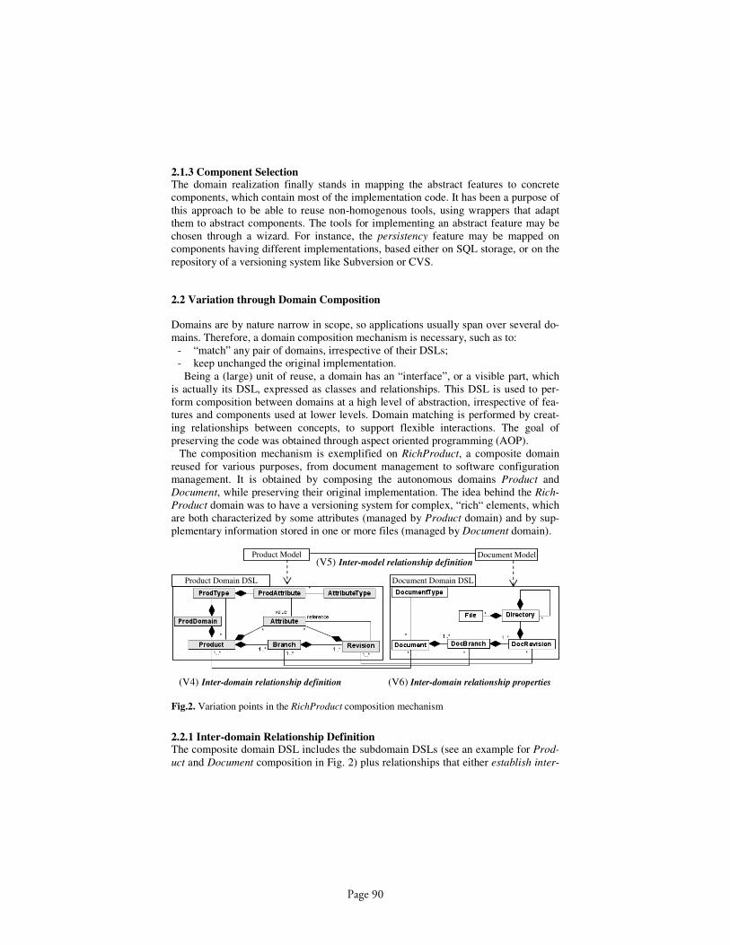
2.1.3 Component Selection The domain realization finally stands in mapping the abstract features to concrete
components, which contain most of the implementation code. It has been a purpose of
this approach to be able to reuse non-homogenous tools, using wrappers that adapt
them to abstract components. The tools for implementing an abstract feature may be
chosen through a wizard. For instance, the persistency feature may be mapped on
components having different implementations, based either on SQL storage, or on the
repository of a versioning system like Subversion or CVS.
2.2 Variation through Domain Composition
Domains are by nature narrow in scope, so applications usually span over several do-
mains. Therefore, a domain composition mechanism is necessary, such as to:
- “match” any pair of domains, irrespective of their DSLs;
- keep unchanged the original implementation.
Being a (large) unit of reuse, a domain has an “interface”, or a visible part, which
is actually its DSL, expressed as classes and relationships. This DSL is used to per-
form composition between domains at a high level of abstraction, irrespective of fea-
tures and components used at lower levels. Domain matching is performed by creat-
ing relationships between concepts, to support flexible interactions. The goal of
preserving the code was obtained through aspect oriented programming (AOP).
The composition mechanism is exemplified on RichProduct, a composite domain
reused for various purposes, from document management to software configuration
management. It is obtained by composing the autonomous domains Product and
Document, while preserving their original implementation. The idea behind the Rich-
Product domain was to have a versioning system for complex, “rich“ elements, which
are both characterized by some attributes (managed by Product domain) and by sup-
plementary information stored in one or more files (managed by Document domain).
(V5) Inter-model relationship definition
(V4) Inter-domain relationship definition (V6) Inter-domain relationship properties
Product Model Document Model
Product Domain DSL Document Domain DSL
Fig.2. Variation points in the RichProduct composition mechanism
2.2.1 Inter-domain Relationship Definition The composite domain DSL includes the subdomain DSLs (see an example for Prod-
uct and Document composition in Fig. 2) plus relationships that either establish inter-
Page 90

actions characteristic to the new composite domain, or link “the same” concept found
in both domains - called inter-domain relationships (for example Product – Docu-
ment or Revision – DocRevision, representing the variation point V4 from Fig.2)
Inter-domain relationships are not modifying the code of the original domains; links
and interactions are implemented in a non-invasive way, using AOP.
2.2.2 Inter-model Relationship Definition An application pertaining to a composite domain is characterized by several models,
one for each of the composed domains. For developing a new application, the applica-
tion designer should select a model from each domain and should define the relation-
ships between these models, in conformity with the previously described inter-domain
relationships. These inter-model relationships (variation point V5 from Fig. 2) may be
established either automatically (if there are enough criteria for matching the model
elements) or manually, through another Mélusine wizard (methodological details
were given in [7]).
2.2.3 Inter-domain Relationship Properties The inter-domain relationships in composite domains are characterised by several
properties, which also constitute the variation points of our composition mechanism
(see V6 from Fig.2). Some characteristic attributes are given below:
a) Destination Life Cycle Management:
- Source Independent - if objects from the source and destination classes are
created independently and then related by an implicit or an explicit selection;
this is similar to an association in UML;
- Source Dependent - if the life cycle of the objects instantiated from the desti-
nation class is managed by the objects instantiated from the source class; these
relationships are similar to UML composition but the implementation is dif-
ferent from a composition between classes belonging to the same model.
In our example, the documents life cycle, with branches and revisions, is under the
control of products, with their respective revision tree. Thus, the destination life cycle
is dependent on the source one.
b) Multiplicity – an object from the source class may be linked to one or more ob-
jects from the destination class and vice-versa; the link may be optional or not.
Multiplicity may vary with respect to the composition policy and strongly depends on
the context in which the composed domains will be used. Let us take as example the
multiplicity choice for the Revision class related to DocRevision. What happens
when the product attributes change, while the document content remains the same? If
the multiplicity is 1..*, a document revision may be linked to more product revisions.
c) Link Creation Moment - represents the moment at which the source and destina-
tion instances are linked:
- Early, at instantiation - means creating the link immediately after the instantia-
tion of the source;
- Late, at navigation - means creating the link when navigation requires the des-
tination object;
In RichProduct,, a document is instantiated immediately after creating a product and
linked to it. So happens to branches and revisions also.
Page 91

d) Persistence – if the link is persistent and must be recreated in case of failure;
e) Captures - the signature of methods that have to be captured for supporting inter-
actions across the relationship.
Mélusine environment includes a user interface that asks the composite domain
developer to make the right choice for these properties. The code for implementing
the above properties (like establishing and navigating the links, persistency, or desti-
nation object creation) is generated automatically in the form of AspectJ extensions.
Other complex interactions between the linked objects should however be manually
coded, on the basis of the skeleton generated for the captures.
3 Conclusion
The increase of size, complexity and evolution requires more flexible composition
mechanisms, such as to manage variation points inside the units of reuse, but also in
the composition mechanisms itself. This may be obtained through model-based com-
position, at a high level of abstraction. This paper presents such a composition
mechanism for high granularity units of reuse called domains. Any pair of domains
may be composed by establishing inter-domain relationships, whose properties repre-
sent variation points of the composition.
Acknowledgments. The work of Anca Daniela Ionita was supported by a FP6, Marie
Curie – EIF fellowship at LIG-IMAG and by MEC-CNCSIS A37 grant.
References
1. van Ommering, R., Bosch, J.: Widening the Scope of Software Product Lines – From
Variation to Composition. In: G. Chastek (Ed.): SPLC2 2002. LNCS 2379 (2002) 328-
347
2. Favre, J.M.: Towards a Basic Theory to Model Driven Engineering. 3rd Workshop in
Software Model Engineering, WiSME 2004 (2004)
3. Bruneton, E., Coupaye, T., Stefani, J.B.: Recursive and Dynamic Software Composition
with Sharing. Seventh International Workshop on Component-Oriented Programming
(WCOP02), Malaga, Spain (2002)
4. Peltz, D.: Web services orchestration. A review of emerging technologies, tools and stan-
dards. Hewlett Packard, Co., January (2003)
5. van Ommering, R., Beyond Product Families: Building a Product Population ?. In: F. van
der Linden (Ed.): IW-SAPF-3, LNCS 1951 (2000) 187-198
6. Estublier, J., Vega, G., Ionita, A.D.: Composing Domain-Specific Languages for Wide-
Scope Software Engineering Applications. Lecture Notes in Computer Science. Proceed-
ing of MoDELS/UML Conference, Jamaica 3713 (2005) 69 – 83.
7. Estublier, J., Ionita, A.D., Vega, G.: Relationships for Domain Reuse and Composition.
Journal of Research and Practice in Information Technology, 38, 4 (2006) 287-301
8. Riebisch M., Streitferdt D., Pashov I.: Modeling Variability for Object-Oriented Product
Lines. Workshop Reader of 17th European Conference on Object Oriented Programming
ECOOP 2003, Darmstadt, Germany (2003) 165-178
Page 92

Towards Integration of Modelling and ReusingSoftware Cases
Katharina Wolter1, Lothar Hotz1, and Thorsten Krebs1
HITeC e.V. c/o Department Informatik, Universitat HamburgHamburg, Germany, 22527
{hotz|krebs|kwolter}@informatik.uni-hamburg.de
Abstract. This paper introduces a novel approach to integrate reuse ofsoftware cases and dynamic variability modelling. Software cases com-prise both a problem description in form of a requirements specificationand a solution in form of architecture, design and code. Previous soft-ware cases are identified based on the requirements specification and canbe reused for different but similar problems. This paper describes workin progress. The ideas stem from research work within the EU-fundedproject ReDSeeDS (Requirements-driven Software Development)1.
1 Introduction
The necessity to enhance reuse in software development is known. Software prod-uct lines and variability modelling are well-known approaches to reach this goal[1] [2]. Adopting these approaches, the variability of the domain is modelled inadvance to software development and is reused during application engineering.
In this paper, we propose a novel approach in which reuse is based on softwarecases and variability can be modelled during software development. Using thisapproach, the additional effort for variability modelling is kept minimal. Ourapproach clearly differs from the software product line approach. New variabilityand new artefacts are defined during application engineering, when needed. Theapproach can be seen as a complement or alternative to the strict separation ofapplication engineering and domain engineering which is typical for developmentin software product lines.
A software case comprises a problem statement (requirements) and a solution(architecture, design and implementation) [3]. The requirements specification ismapped to appropriate elements of the solution. Between the solution elements,there is also a mapping defined: i.e. between requirements and architecture, be-tween architecture and design, and between design and code. For a more detaileddescription of this approach we refer the interested reader to [3].
All software cases of one domain are collected in a software knowledge model.While a single software case does not contain any variability, each new softwarecase introduces new variability. The variability in the software knowledge model
1 http://www.redseeds.eu
Page 93

2 Katharina Wolter, Lothar Hotz and Thorsten Krebs
is exploited during software development as follows. Based on a partial require-ments specification similar software cases are identified [3]. From these retrievedsoftware cases, both requirements and the corresponding solutions can be reused.The resulting new software case is added to the software knowledge model.
In order to compute similarity between different software cases it is apparentthat the software knowledge model must be consistent at any time. A challengeto this is the fact that customers use their own, probably domain-specific, ter-minology. Hence, there is no explicit one-to-one mapping from the requirementsof a new software case to requirements of stored software cases. For keeping re-quirements customer-understandable, but being able to map their requirementsto stored cases, a local vocabulary is created for every software case. Terms of thisvocabulary contain a mapping to terms defined in a global, common vocabularywhich is maintained within the software knowledge model. The mapping betweenthe local vocabulary and the common vocabulary can be one-to-one, but also in-clude synonym and homonym definitions. Whenever requirements specificationscontain new terms that the global vocabulary does not yet contain or termsused with a different meaning, these are integrated into the common vocabu-lary – henceforth called consolidated vocabulary. This approach allows to definedifferent, customer-related terminologies but nonetheless using the full power ofsimilarity-based identification and reuse of different software cases. The softwareknowledge model grows incrementally and thus can become very large. In orderto ensure consistency, tool support is essential.
The remainder of the paper is organised as follows. First, we illustrate howsoftware development looks like using a software knowledge model for definingvariability of stored software cases (2.1). Then we detail the software knowledgemodel (2.2) and show how similarity of software cases can be computed basedon the consolidated vocabulary (2.3). We discuss and compare the approach torelated work (3), present future work and finally summarise the main benefits(4). Throughout the paper we use examples from the domain of managementsoftware applied for a fitness club.
2 Case-base variability modelling
2.1 Vision
Within the ReDSeeDS approach [4, 3], reuse already starts during requirementsspecification. The Requirements Engineer (RE) defines requirements e.g. in aset of scenarios2. Each scenario is a sequence of sentences written in restrictedEnglish3, called requirements statements. A tool supports the RE during re-quirements specification. When the RE enters a new sentence the tool checks2 Note that the ReDSeeDS approach also supports other forms of requirements spec-
ifications. Fore simplicity reasons we restrict ourselves to scenarios in this paper.3 One example of restricted English is Subject-verb-object (SVO) sentences where the
subject comes first, the verb second and the object third [5]. There are also otherapproaches to restrict English text, like the Attempto Controlled English (ACE).The extended form of SVO sentences used in ReDSeeDS have the advantage of
Page 94
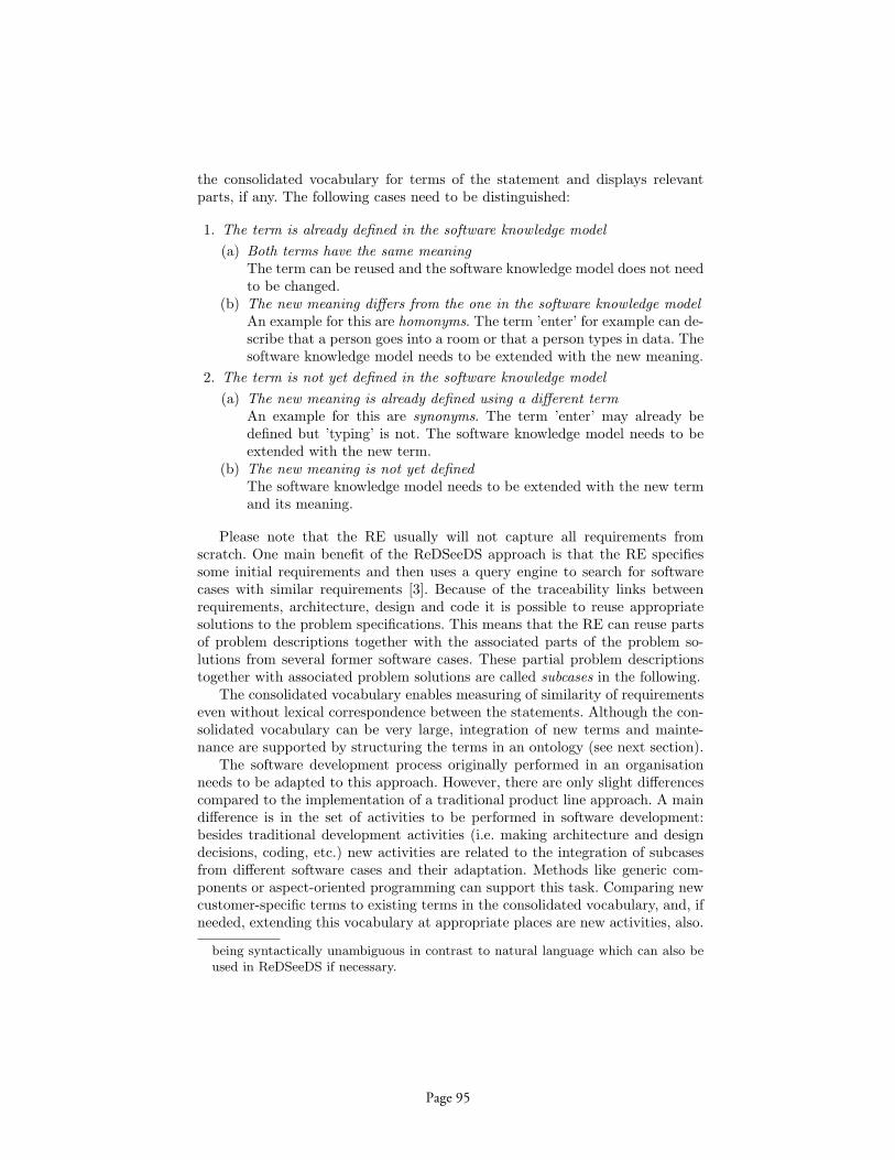
Modelling and Reusing Software Cases 3
the consolidated vocabulary for terms of the statement and displays relevantparts, if any. The following cases need to be distinguished:
1. The term is already defined in the software knowledge model(a) Both terms have the same meaning
The term can be reused and the software knowledge model does not needto be changed.
(b) The new meaning differs from the one in the software knowledge modelAn example for this are homonyms. The term ’enter’ for example can de-scribe that a person goes into a room or that a person types in data. Thesoftware knowledge model needs to be extended with the new meaning.
2. The term is not yet defined in the software knowledge model(a) The new meaning is already defined using a different term
An example for this are synonyms. The term ’enter’ may already bedefined but ’typing’ is not. The software knowledge model needs to beextended with the new term.
(b) The new meaning is not yet definedThe software knowledge model needs to be extended with the new termand its meaning.
Please note that the RE usually will not capture all requirements fromscratch. One main benefit of the ReDSeeDS approach is that the RE specifiessome initial requirements and then uses a query engine to search for softwarecases with similar requirements [3]. Because of the traceability links betweenrequirements, architecture, design and code it is possible to reuse appropriatesolutions to the problem specifications. This means that the RE can reuse partsof problem descriptions together with the associated parts of the problem so-lutions from several former software cases. These partial problem descriptionstogether with associated problem solutions are called subcases in the following.
The consolidated vocabulary enables measuring of similarity of requirementseven without lexical correspondence between the statements. Although the con-solidated vocabulary can be very large, integration of new terms and mainte-nance are supported by structuring the terms in an ontology (see next section).
The software development process originally performed in an organisationneeds to be adapted to this approach. However, there are only slight differencescompared to the implementation of a traditional product line approach. A maindifference is in the set of activities to be performed in software development:besides traditional development activities (i.e. making architecture and designdecisions, coding, etc.) new activities are related to the integration of subcasesfrom different software cases and their adaptation. Methods like generic com-ponents or aspect-oriented programming can support this task. Comparing newcustomer-specific terms to existing terms in the consolidated vocabulary, and, ifneeded, extending this vocabulary at appropriate places are new activities, also.
being syntactically unambiguous in contrast to natural language which can also beused in ReDSeeDS if necessary.
Page 95
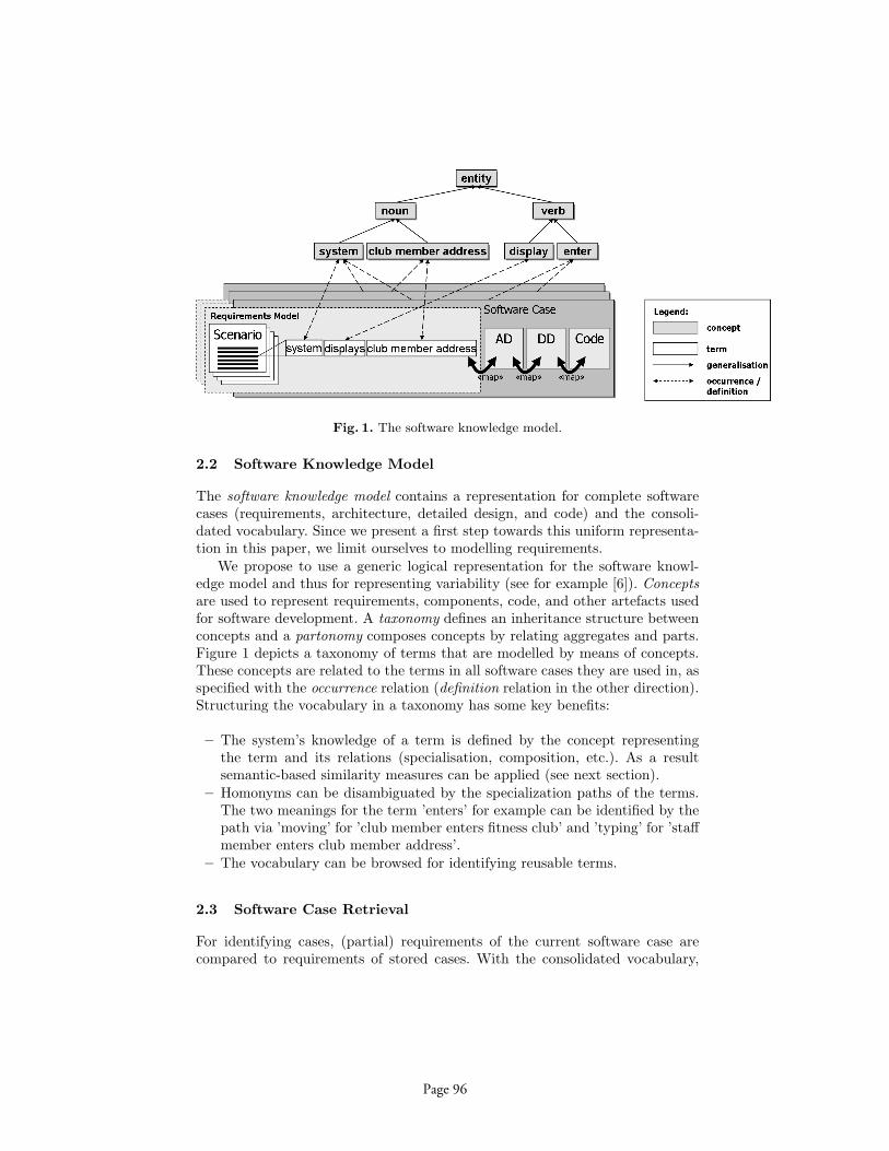
4 Katharina Wolter, Lothar Hotz and Thorsten Krebs
Fig. 1. The software knowledge model.
2.2 Software Knowledge Model
The software knowledge model contains a representation for complete softwarecases (requirements, architecture, detailed design, and code) and the consoli-dated vocabulary. Since we present a first step towards this uniform representa-tion in this paper, we limit ourselves to modelling requirements.
We propose to use a generic logical representation for the software knowl-edge model and thus for representing variability (see for example [6]). Conceptsare used to represent requirements, components, code, and other artefacts usedfor software development. A taxonomy defines an inheritance structure betweenconcepts and a partonomy composes concepts by relating aggregates and parts.Figure 1 depicts a taxonomy of terms that are modelled by means of concepts.These concepts are related to the terms in all software cases they are used in, asspecified with the occurrence relation (definition relation in the other direction).Structuring the vocabulary in a taxonomy has some key benefits:
– The system’s knowledge of a term is defined by the concept representingthe term and its relations (specialisation, composition, etc.). As a resultsemantic-based similarity measures can be applied (see next section).
– Homonyms can be disambiguated by the specialization paths of the terms.The two meanings for the term ’enters’ for example can be identified by thepath via ’moving’ for ’club member enters fitness club’ and ’typing’ for ’staffmember enters club member address’.
– The vocabulary can be browsed for identifying reusable terms.
2.3 Software Case Retrieval
For identifying cases, (partial) requirements of the current software case arecompared to requirements of stored cases. With the consolidated vocabulary,
Page 96
Modelling and Reusing Software Cases 5
the terms of all software case are comparable: the ontological structure can beexploited to identify similarity of terms from different cases.
A child concept is similar to its parent because the former is a specializationof the latter. Two siblings are also similar because both are children of the sameparent (they inherit the same characteristics). Concepts in different places ofthe taxonomy are not necessarily similar. For example ’staff member’ and ’clubmember’ are both ’person’s which means that they are siblings and have a lot incommon (e.g. name, address, etc.) compared to a ’staff member’ and a ’bracelet’which is a ’thing’. Several heuristic similarity measures that are based on acommon hierarchial structure of terms are described in [7].
3 Discussion and Related Work
In case-based reasoning, cases (i.e. past experience) are stored to be retrieved forsimilar problems [8]. The solution in the retrieved case is examined and appliedto the current problem with suitable modifications. While most case-based ap-proaches to software reuse apply reuse on the level of software components andcode [9], ReDSeeDS starts reuse already on the level of requirements. This is anessential advantage due to the fact that former cases can be identified early andrequirements specification can be skipped when requirements are reused togetherwith the solution.
Software Product Lines (SPLs) are a means for large-scale reuse. A productline contains a set of products that share a common, managed set of featuressatisfying the specific needs of a particular market segment or mission [1]. Do-main engineering plays a key role: analysing the product domain, building acommon architecture and planning reuse. Variability is modelled explicitly e.g.in a feature model. This modelling can be done in a waterfall-like approach orincrementally. Our approach models variability is implicitly through the differentsoftware cases. In contrast to a-priori domain engineering, our approach enablesdynamic extension of the reusable asset repository, i.e. reuse is not planned a-priori. Evolving the model during product development contains both, evolvingthe problem description (vocabulary, scenarios, etc.) and including the solutionto the problem (i.e. architecture, design and code). This means that domainengineering is not a separate tasks but done during application development.In SPL reusable artefacts are determined using a variability model while in theReDSeeDS approach these artefacts are identified by searching for software caseswith similar requirements.
4 Summary and Future Work
In this paper, we have introduced a novel approach that integrates variabilitymodelling and reuse of former software cases. A software case comprises theproblem description in form of a requirements specification and a solution de-scription in form of architecture, detailed design and code artefacts. Reusing
Page 97
6 Katharina Wolter, Lothar Hotz and Thorsten Krebs
software cases or subcases is enabled with a query engine that compares re-quirements specifications of former cases to the current problem. Variability ismodelled implicitly by the set of all known software cases and is automaticallyextended for every new software case that is developed and stored.
The ideas in this paper originate from research work within the ReDSeeDSproject, in which a similarity measure will be developed based on the con-solidated vocabulary sketched in this paper. The AMPL (Asset Modelling forProduct Lines) language developed in the ConIPF (Configuration in IndustrialProduct Families)4 project defines a language to represent complete productknowledge (incl. features, context, software and hardware artefacts) [6]. Thesemodelling facilities will be extended to formalize requirements, architecture, de-sign and code. The adaptation of subcases from former software cases and theintegration of subcases from different software cases are further challenges.
Acknowledgement
This work is partially funded by the EU: Requirements-driven Software Devel-opment System (ReDSeeDS) (contract no. IST-2006-33596). The project is coor-dinated by Infovide, Poland with technical lead of Wasaw University of Technol-ogy and with University of Koblenz-Landau, Vienna University of Technology,Fraunhofer IESE, University of Latvia, HITeC e.V. c/o University of Hamburg,Heriot-Watt University, PRO DV, Cybersoft and Algoritmu Sistemos.
References
1. Clements, P., Northrop, L.: Software Product Lines: Practices and Patterns.Addison-Wesley (2002)
2. Kang, K., Cohen, S., Hess, J., Novak, W., Peterson, S.: Feature-oriented DomainAnalysis (FODA) Feasibility Study. Technical Report CMU/SEI-90-TR-021 (1990)
3. Smialek, M.: Towards a Requirements driven Software Development System. In:Models 2006. (2006)
4. Smialek, M.: Acoomodating Informality with Necessary Precision in Use Case Senar-ios. Journal of Object Technology 4(8) (2005) 59–67
5. Graham, I.: Task scripts, use cases and scenarios in object oriented analysis. ObjectOriented Systems 3 (1996) 123–142
6. Hotz, L., Wolter, K., Krebs, T., Deelstra, S., Sinnema, M., Nijhuis, J., MacGregor,J.: Configuration in Industrial Product Families - The ConIPF Methodology. IOSPress, Berlin (2006)
7. Pedersen, T., Patwardhan, S., Michelizzi, J.: Wordnet::similarity - measuring therelatedness of concepts. In: In Proceedings of the Nineteenth National Conferenceon Artificial Intelligence (AAAI-04). (2004)
8. Aamodt, A., Plaza, E.: Case-based reasoning: Foundational issues, methodologi-cal variations, and system approaches. Artificial Intelligence Communications 7(1)(1994) 39–59
9. Fouque, G., Matwin, S.: A case-based approach to software reuse. Journal ofIntelligent Information Systems 2(2) (1993) 165–197
4 http://www.conipf.org
Page 98

Goal and Variability Modeling for Service-oriented Systems: Integrating
i* with Decision Models
P. Grün-bacher1
D. Dhun-gana1
N. Seyff2
M. Quintus2
R. Clotet3
X. Franch3
L. López3
J. Marco3
Christian Doppler Lab for Automated Software Eng.1 Johannes Kepler University
4040 Linz, Austria
Systems Engineering and Automation2
Johannes Kepler University4040 Linz, Austria
Universitat Politècnica de Catalunya (UPC)3
Barcelona, Spain
Abstract. Variability modeling and service-orientation are important ap-proaches that address both the flexibility and adaptability required by stake-holders of today’s software systems. Goal-oriented approaches for modeling service-oriented systems and their variability in an integrated manner are needed to address the needs of heterogeneous stakeholders and to develop and evolve these systems. In this paper we propose an approach that complements the i* modeling framework with decision models from orthogonal variability modeling. We illustrate the approach using an example and present options for tool support.
1 Introduction
Stakeholders of today’s software-intensive systems demand flexibility and adaptabil-ity to allow rapid system evolution made necessary by new and changing require-ments. Variability modeling and service-orientation are promising with respect to both flexibility and adaptability. Variability modeling is an approach fostering soft-ware reuse and rapid customization of systems [8][10]. Service-orientation is visible in buzzwords such as service-oriented computing, service-oriented architectures, or service-oriented software engineering and is promoted by a number of emerging standards for service-oriented development. Recently, researchers have started to explore the integration of service-oriented systems and variability modeling. Variabil-ity modeling is increasingly seen as a mechanism to support run-time evolution and dynamism in different domains and to design, analyze, monitor, and adapt service-oriented systems [7]. At the same time the modeling framework i* [11] is gaining popularity to model service-oriented and agent-based systems [9] and researchers are seeking new ways to enhance it with variability modeling capabilities [6].
Pursuing similar goals we have been using i* to model a service-oriented multi-stakeholder distributed system (MSDS) in the travel domain to validate its usefulness
Page 99

in this context [3]. Despite the power and expressiveness of i* we experienced some deficiencies when modeling variability in particular when specifying the needs of heterogeneous stakeholders in the MSDS or when investigating the modeling needs of service provides and service integrators. As a result we started investigating the dependencies of goal modeling and variability modeling. In this paper we discuss an initial approach integrating orthogonal variability modeling techniques into i*. We illustrate the approach using examples and discuss tentative tool support based on our existing work on meta-tools for variability modeling. Our approach is based on our integration framework [3] as well as our earlier work on the use of i* [5] and variabil-ity modeling [4].
2 Modeling the Variability of Service-oriented Systems with i*
Modeling service-oriented systems requires an understanding of stakeholder goals and goal variability. i* is an established framework for goal modeling [11] which is goal-oriented as well as actor-oriented and supports the assignment of responsibilities to system actors to express high-level actor requirements. There are two types of models in i*: Strategic Dependency (SD) models define actors, their relationships (e.g., specialization and composition) and how they depend on each other. Strategic Rationale (SR) models state the main goals of these actors and their decomposition using some refinement constructs. Together the SD and SR models provide a com-prehensive system overview. i* supports recording the rationale behind requirements and decomposing elicited requirements at the required level of detail. At the require-ments level actors are mainly used to represent stakeholders’ needs, while at the ar-chitecture levels they can be used to model services: For instance, Franch and Maiden have explored the use of i* to model architectures using roles and agents [5]. A simi-lar approach has been proposed by Penserini et al. in [9]. i* supports traceability from high-level actor goals to concrete services in the running system and vice versa. It has been shown that high-level stakeholder goals tend to be more stable than underlying requirements and selected software solutions. Linking services to high-level stake-holder goals modeled in i* thus increases system stability and adaptability by guiding the replacement of malfunctioning services with services also fulfilling essential stakeholder goals. It also facilitates the identification of affected stakeholders [3].
Fig 1. Modeling Goal Variability in i*: Customer assistance can be either provided
using asynchronous or synchronous support.
Page 100
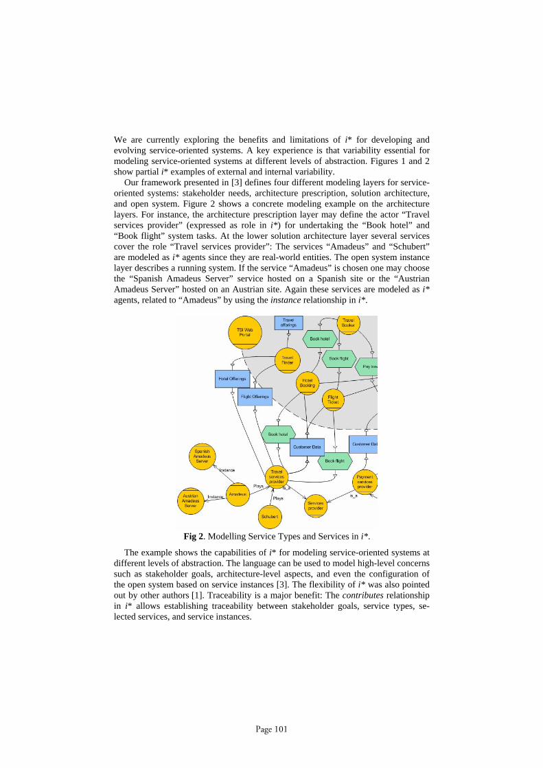
We are currently exploring the benefits and limitations of i* for developing and evolving service-oriented systems. A key experience is that variability essential for modeling service-oriented systems at different levels of abstraction. Figures 1 and 2 show partial i* examples of external and internal variability.
Our framework presented in [3] defines four different modeling layers for service-oriented systems: stakeholder needs, architecture prescription, solution architecture, and open system. Figure 2 shows a concrete modeling example on the architecture layers. For instance, the architecture prescription layer may define the actor “Travel services provider” (expressed as role in i*) for undertaking the “Book hotel” and “Book flight” system tasks. At the lower solution architecture layer several services cover the role “Travel services provider”: The services “Amadeus” and “Schubert” are modeled as i* agents since they are real-world entities. The open system instance layer describes a running system. If the service “Amadeus” is chosen one may choose the “Spanish Amadeus Server” service hosted on a Spanish site or the “Austrian Amadeus Server” hosted on an Austrian site. Again these services are modeled as i* agents, related to “Amadeus” by using the instance relationship in i*.
Fig 2. Modelling Service Types and Services in i*.
The example shows the capabilities of i* for modeling service-oriented systems at different levels of abstraction. The language can be used to model high-level concerns such as stakeholder goals, architecture-level aspects, and even the configuration of the open system based on service instances [3]. The flexibility of i* was also pointed out by other authors [1]. Traceability is a major benefit: The contributes relationship in i* allows establishing traceability between stakeholder goals, service types, se-lected services, and service instances.
Page 101
The examples, however, also show some limitations of modeling variability in i*. The expressiveness and formality is insufficient compared to existing variability mod-eling approaches. There are no language constructs to capture more formal aspects required in variability models such as constraints (e.g., between services), conditions under which services become active or inactive, selector types, or cardinalities [10]. The variability modeling capabilities of i* should therefore be enhanced.
3 Using Variability Modeling with i*
We propose an approach based on our framework for multi-stakeholder distributed systems [3] and our earlier work on the use of i* [5] and meta-tools for variability modeling [4]. A fundamental approach in variability modeling is to complement ex-isting models and artifacts with variability information rather than using specific notations or languages. Our work is influenced by a decision-oriented approach pro-posed by Schmid and John [10] that supports orthogonal variability modeling for arbitrary artifacts independent from a specific notation. The benefits of such ap-proaches are the flexibility gained and traceability established by using one variability mechanisms for different artifacts at the requirements, design, architecture, imple-mentation, application, and runtime level. We propose to complement i* with or-thogonal variability modeling techniques. Such an approach requires:
• The development of a decision model describing the variability of the system and dependencies between variabilities [4].
• An asset model describing the system elements and their dependencies [4]. In the domain of service-oriented systems the elements include service types, services, and service instances together with their dependencies (e.g. a pay-ment service might rely on a transaction service).
• The annotation of i* models with rules referring to the decision model to model inclusion conditions for services and the dependencies among assets and decisions.
• A mechanism to prune i* models based decisions taken at design-time or runtime to generate/update system configurations on the fly (e.g., by add-ing/removing/updating services).
We envisage an i* model to hold a snapshot of a service-oriented system at a certain point in time that can be adapted based on decisions taken by stakeholders by consid-ering all assets and their dependencies. In the product line terminology such a snap-shot is based on the domain-level, ”product-line“ version of the i* model. Obviously, beyond the i* model, the runtime configuration requires the generation of additional information for configuration, i.e., concrete values of decision variables that inform system configuration (see Figure 3).
Page 102
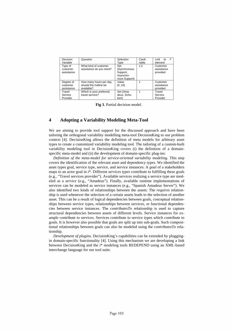
Decision Variable
Question Selection Type
Cardi- nality
Link to i* element
Type of customer assistance
What kind of customer assistance do you need?
Set {Synchronous Support, Asynchro-nous Support}
1:2 Customer assistance provided
Degree of customer assistance
How many hours per day should the hotline be available?
Value [0..24]
1 Customer assistance provided
Travel Service Provider
Which is your preferred travel service?
Set (Ama-deus, Schu-bert)
1 Travel Service Provider
Fig 3. Partial decision model.
4 Adopting a Variability Modeling Meta-Tool
We are aiming to provide tool support for the discussed approach and have been tailoring the orthogonal variability modelling meta-tool DecisionKing to our problem context [4]. DecisionKing allows the definition of meta models for arbitrary asset types to create a customized variability modeling tool. The tailoring of a custom-built variability modeling tool in DecisionKing covers (i) the definition of a domain-specific meta-model and (ii) the development of domain-specific plug-ins:
Definition of the meta-model for service-oriented variability modeling. This step covers the identification of the relevant asset and dependency types. We identified the asset types goal, service type, service, and service instances: A goal of a stakeholders maps to an actor goal in i*. Different services types contribute to fulfilling these goals (e.g., “Travel services provider”). Available services realizing a service type are mod-eled as a service (e.g., “Amadeus”). Finally, available runtime implementations of services can be modeled as service instances (e.g., “Spanish Amadeus Server”). We also identified two kinds of relationships between the assets: The requires relation-ship is used whenever the selection of a certain assets leads to the selection of another asset. This can be a result of logical dependencies between goals, conceptual relation-ships between service types, relationships between services, or functional dependen-cies between service instances. The contributesTo relationship is used to capture structural dependencies between assets of different levels. Service instances for ex-ample contribute to services. Services contribute to service types which contribute to goals. It is however also possible that goals are split up into sub-goals. Such composi-tional relationships between goals can also be modeled using the contributesTo rela-tionship.
Development of plugins. DecisionKing’s capabilities can be extended by plugging-in domain-specific functionality [4]. Using this mechanism we are developing a link between DecisionKing and the i* modeling tools REDEPEND using an XML-based interchange language for our tool suite.
Page 103

5 Open Issues
In this paper we proposed an initial approach to complement i* with an orthogonal variability modeling technique. There are several open issues needing attention:
We need to extend the i* language in order to include variability information. On the one hand, we need to provide complete formal semantics for the is_a inheritance i* mechanism, which is currently only defined at the actor level. On the other hand, we need to provide a formal syntax for modeling taken decisions (e.g., which services are chosen) and variation points. We are considering the use of the i* routine concept for reflection decisions taken in the model.
We also need to complete tool integration to improve traceability between i* and variability models. For this purpose we will link the i* meta-model and the variability meta-model and exchange information between models using an XML interchange definition language currently under definition.
References
[1] J. Castro, M. Kolp, J. Mylopoulos. “Towards Requirements-Driven Information Systems Engineering: The Tropos Project”. Information Systems, vol. 27, 2002. [2] L. Chung, B.A. Nixon, E. Yu, J. Mylopoulos, Non-functional requirements in software engineering, Kluwer Academic Publishers, 2000. [3] R. Clotet, X. Franch, P. Grünbacher, L. López, J. Marco, M. Quintus, N. Seyff: “Require-ments Modelling for Multi-Stakeholder Distributed Systems: Challenges and Techniques”. RCIS'07: 1st IEEE Int. Conf. on Research Challenges in IS, Ouarzazate, 2007 [4] D. Dhungana, P. Grünbacher, and R. Rabiser, "DecisionKing: A Flexible and Extensible Tool for Integrated Variability Modeling.", 1st International Workshop on Variability Model-ling of Software-intensive Systems, Limerick, Ireland, 2007. [5] X. Franch, N.A.M. Maiden. “Modeling Component Dependencies to Inform their Selec-tion”. In Proceedings 2nd International Conference on COTS-Based Software Systems (ICCBSS), Lecture Notes on Computer Science 2580, Springer,2003. [6] S. Liaskos, Y. Yu, E. Yu, J. Mylopoulos. “On Goal-based Variability Acquisition and Analysis”. Proc. 14th IEEE Int’l Requirements Engineering Conference (RE'06) (Sept 11-15, 2006). IEEE Computer Society [7] J. Peña, M.G. Hinchey, A. Ruiz-Cortés. “Multi-agent system product lines: challenges and benefits”. Communications of the ACM, vol. 49, n. 12 (Dec. 2006), 82-84. [8] K. Pohl, G. Böckle, and F. J. van der Linden, Software Product Line Engineering: Founda-tions, Principles, and Techniques: Springer, 2005. [9] L. Penserini, A. Perini, A. Susi, J. Mylopoulos. "From Stakeholder Needs to Service Re-quirements". Proceedings of the 2nd International Workshop on Service-Oriented Computing: Challenges on Engineering Requirements (SOCCER), 2006. [10] K. Schmid and I. John, "A Customizable Approach to Full-Life Cycle Variability Man-agement". Journal of the Science of Computer Programming, Special Issue on Variability Management, vol. 53(3), pp. 259-284, 2004. [11] E. Yu. Modeling Strategic Relationships for Process Reengineering, PhD Thesis, To-ronto, 1995.
Page 104