
OREGON LANDSCAPE GUIDELINES - MemberClicks · 2016-01-14 · 10.03 landscape design phase 81-82 a....
169
Oregon Landscape Guidelines March 2004 OREGON LANDSCAPE GUIDELINES Developed by the OREGON LANDSCAPE CONTRACTORS ASSOCIATION PREPARED BY: RICHARD L. HOLLENBECK EDITED BY: O.L.C.A. GUIDELINES COMMITTEE Martin L. Gascoyne, Committee Chairperson, Lane County Lisa Walter-Sedlacek, Lane County Matt Triplett, CLP, CLT, Portland Stacey Werner, CLP, CLT, Portland Chris Stout, CLP, CLT, Portland Rick Christensen, Portland Scott Winkelman, CLP, Portland John Galbraith, Southern Oregon Robbin Pearce, C.L.I.A., Southern Oregon Joe Lymp, C.L.I.A., Central Oregon Ken DeSantis CLP, CLT, Salem/Mid-Valley ILLUSTRATIONS BY: Douglas Rothe
Transcript of OREGON LANDSCAPE GUIDELINES - MemberClicks · 2016-01-14 · 10.03 landscape design phase 81-82 a....

Oregon Landscape Guidelines March 2004
OREGON LANDSCAPE GUIDELINES
Developed by the
OREGON LANDSCAPE CONTRACTORS ASSOCIATION
PREPARED BY: RICHARD L. HOLLENBECK
EDITED BY: O.L.C.A. GUIDELINES COMMITTEE Martin L. Gascoyne, Committee Chairperson, Lane County
Lisa Walter-Sedlacek, Lane County Matt Triplett, CLP, CLT, Portland
Stacey Werner, CLP, CLT, Portland Chris Stout, CLP, CLT, Portland
Rick Christensen, Portland Scott Winkelman, CLP, Portland John Galbraith, Southern Oregon
Robbin Pearce, C.L.I.A., Southern Oregon Joe Lymp, C.L.I.A., Central Oregon
Ken DeSantis CLP, CLT, Salem/Mid-Valley
ILLUSTRATIONS BY: Douglas Rothe
Oregon Landscape Guidelines March 2004
i
INTRODUCTION ________________________________________________________________________
These guidelines were written for those individuals and companies involved in the
landscape construction industry in the State of Oregon. Their purpose is to serve as a
reference for minimum standards for the industry, a guide for the landscape contractor
and as a learning tool for students and employees studying landscape construction. The
information presented reflects the requirements for landscape contracting as set forth by
the State of Oregon at the time of this writing. The information presented applies to
specific landscape operations. The basic elements are presented in the order a full
landscape installation might be completed.
In using these guidelines, it should be kept in mind that they do not address all
possibilities nor do they answer all questions. The guidelines are the recommended
minimum and the word ’should’ is used in place of the word ‘shall’ as used in written
specifications, national, state and local codes and/or ordinances. The guidelines are not
meant to replace written specifications, code or law requirements as set forth by legal
jurisdictions.
Richard L. Hollenbeck
The OLCA Guidelines Committee has spent an enormous amount of time reviewing and
editing this document. We were guided in our efforts by three major considerations.
First, the document should reflect minimum guidelines, not best management practices.
Second, the document should not infringe on the creative process unnecessarily. Third,
that regional differences should be accounted for.
While this document reflects the committee’s best efforts to accomplish that, they still
remain just guidelines. Many of the illustrations convey just one way of accomplishing a
task, and they should not be viewed as limitations. The final decisions about what work
is going to be done and how it is going to be achieved must be outlined in the written
contract negotiated between the contractor and the client.
Martin L.Gascoyne
Oregon Landscape Guidelines March 2004
ii
TABLE OF CONTENTS
SECTION PAGE NUMBER ________________________________________________________________________
1.0 LANDSCAPE LAWS AND REGULATIONS 1
1.01 STATE RULES AND REGULATIONS 1
1.02 LOCAL RULES AND REGULATIONS 1
1.03 LOCATES 1 ________________________________________________________________________
2.0 GENERAL REQUIREMENTS 2
2.01 DESCRIPTION 2
2.02 GENERAL REQUIREMENTS 2-9 A. SITE PROTECTION B. ENVIRONMENTAL CONDITIONS C. UNDERGROUND UTILITIES D. SAFETY E. EQUIPMENT F. SITE CLEAN-UP
2.03 QUALITY ASSURANCE 9-10 A. REGULATORY REQUIREMENTS B. LICENSING C. TESTING D. INSPECTIONS
2.04 REFERENCES 10
2.05 SUBMITTALS 10-11 A. SHOP DRAWINGS B. SAMPLES C. PERMIT DOCUMENTS D. AS-BUILT DRAWINGS E. EQUIPMENT MANUALS AND DRAWINGS
2.06 SITE CONDITIONS 11-12 A. EXISTING CONDITIONS B. ENVIRONMENTAL REQUIREMENTS
Oregon Landscape Guidelines March 2004
iii
2.07 SCHEDULING 12
2.08 SUBSTITUTIONS 12
2.09 WARRANTY 12 ________________________________________________________________________
3.0 CONSTRUCTION LAYOUT 13
3.01 DESCRIPTION 13
3.02 WORK INCLUDED 13
3.03 CONTRACTOR RESPONSIBILITY 13
3.04 STAKES 14
3.05 FLAGS 14
3.06 LABELS 14 ________________________________________________________________________
4.0 SITE PREPARATION – CLEARING 15
4.01 DESCRIPTION 15
4.02 WORK INCLUDED 15
4.03 EXISTING CONDITIONS 15
4.04 PROTECTIVE FENCING – MATERIALS 15
4.05 PROTECTION OF EXISTING SITE IMPROVEMENTS & PLANTINGS 15
4.06 CLEARING AND GRUBBING 16
4.07 DISPOSAL 17 ________________________________________________________________________
5.0 SITE PREPARATION – GRADING 18
5.01 DESCRIPTION 18
5.02 WORK INCLUDED 18
5.03 QUALITY ASSURANCE 18
5.04 SITE CONDITIONS 18
5.05 CONTRACTOR RESPONSIBILITY 19
Oregon Landscape Guidelines March 2004
iv
5.06 FILL SOIL MATERIAL 19
5.07 TOPSOIL 19
5.08 SLOPE RATIOS 19-20
5.09 ROUGH GRADING 20
5.10 FILL AND COMPACTION 20-21
5.11 TOPSOIL PLACEMENT 21
5.12 FINISH GRADING 21 ________________________________________________________________________
6.0 SITE PREPARATION – GRADING 22
6.01 DESCRIPTION 22
6.02 WORK INCLUDED 22
6.03 QUALITY ASSURANCE 22
6.04 SUBMITTALS 22
6.05 EXISTING CONDITIONS 22
6.06 GENERAL/PRODUCTS 22-23
6.07 DRAINAGE PIPE 23
6.08 MATERIAL STORAGE 23
6.09 INSTALLATION REQUIREMENTS: GENERAL 23-24
6.10 SURFACE DRAINAGE 24-25 A. SYSTEM DESCRIPTION B. FLOOD AND DAMAGE PREVENTION C. MINIMUM SLOPES D. RESTRICTIONS ON OFF-SITE WATER FLOW E. DRAINAGE SWALES
6.11 SUB-SURFACE DRAINAGE 25-28 A. DESCRIPTION OF SYSTEMS B. FRENCH DRAINS C. DIRECTIONAL/AREA DRAINS D. SUB-SURFACE DRAINS: INTERCEPTORS E. SUB-SURFACE DRAINS F. PREFABRICATED DRAIN SYSTEMS

Oregon Landscape Guidelines March 2004
v
6.12 FINAL GRADING AND TESTING 28 A. FINISH GRADES B. TESTING & FLUSHING ________________________________________________________________________
7.0 HARDSCAPES - WOOD CONSTRUCTION 29
7.01 DESCRIPTION 29
7.02 WORK INCLUDED 29
7.03 QUALITY ASSURANCE 29
7.04 SCHEDULING 29
7.05 LUMBER PRODUCTS AND MATERIALS 30-32 A. LUMBER TYPES B. SEASONING C. SIZING D. FASTENERS AND JOINING E. CONNECTORS F. WOOD FINISHES G. CONCRETE H. PIER BLOCKS I. FLASHING
7.06 LAYOUT 32
7.07 LUMBER STORAGE 32
7.08 GENERAL WOOD CONSTRUCTION PRACTICES 33
7.09 FENCE CONSTRUCTION 33-36 A. LUMBER GRADES B. LOCATION C. FENCE HEIGHT D. POST INSTALLATION E. POST ALIGNMENT F. POST SETTING G. RAILS AND BOARD INSTALLATION H. GATE CONSTRUCTION
7.10 DECK CONSTRUCTION 36-41 A. DESCRIPTION B. CONTRACTOR RESPONSIBILITY C. LUMBER GRADES D. PIERS

Oregon Landscape Guidelines March 2004
vi
E. BEAMS AND JOISTS F. LEDGER BOARDS G. DECK FLOORING H. DECK TRIM ` I. STAIRS AND HANDRAILS J. GUARDRAILS
7.11 WOOD STAIRS 42-44 A. DESCRIPTION B. GRADES OF LUMBER C. SUPPORT D. STRINGERS E. RISER/TREAD RATIO F. HANDRAILS
7.12 WOOD BENCHES 45-46 A. DESCRIPTION B. LUMBER GRADES C. POST SUPPORTS D. BENCH SEAT SUPPORTS
7.13 ARBORS 47-49 A. DESCRIPTION B. CONTRACTOR RESPONSIBILITY C. LUMBER GRADES D. LAYOUT E. SUPPORT F. POSTS G. BEAMS H. RAFTERS I. TOP BOARDS
7.14 WOOD RETAINING WALLS 49-51 A. DESCRIPTION B. LUMBER GRADE C. STRUCTURAL DESIGN D. POSTS E. BOARDS F. CAP G. DRAINAGE
7.15 HEADER BOARDS/EDGING 51-54 A. DESCRIPTION B. LUMBER GRADES C. LAYOUT
Oregon Landscape Guidelines March 2004
vii
D. STRAIGHT HEADERS E. HEADERS WITH A SLIGHT CURVE F. HEADERS WITH A STRONG CURVE
G. PLASTIC AND STEEL ________________________________________________________________________
8.0 HARDSCAPES - CONCRETE CONSTRUCTION 55
8.01 GENERAL DESCRIPTION 55
8.02 WORK INCLUDED 55
8.03 QUALITY ASSURANCE 55
8.04 SUBMITTALS 55
8.05 EXISTING CONDITIONS 55
8.06 SCHEDULING 55
8.07 CONTRACTOR RESPONSIBILITY 56
8.08 MATERIALS – CONCRETE CONSTRUCTION 56-57 A. BASE MATERIALS B. REINFORCEMENT C. CONCRETE MIX D. EXPANSION JOINTS E. AGGREGATES FOR SEEDED EXPOSED AGGREGATE F. WATERPROOFING PRODUCTS
8.09 GENERAL REQUIREMENTS – CONCRETE WORK 57-59 A. FORMING B. BURIED INSERTS C. REINFORCEMENT D. EXPANSION AND CONTROL JOINTS E. MOISTURE LEVEL OF SUB-BASE AND BASE F. CONCRETE PLACEMENT G. WALL FINISHES H. FLAT FINISHES
I. CURING J. FORM REMOVAL
8.10 CONCRETE FOOTINGS 59-60 A. DIMENSIONS B. SUB-GRADE C. FORMS D. REINFORCEMENT E. CONCRETE
Oregon Landscape Guidelines March 2004
viii
8.11 RETAINING WALLS – CONCRETE 60-62 A. FORMING B. REINFORCEMENT C. CONCRETE PLACEMENT D. DRAINAGE E. WALL SEALING
8.12 CONCRETE STAIRS 62-63 A. RISE/TREAD RATIO B. SUB-GRADE C. BASE D. FORMING E. REINFORCEMENT F. EXPANSION JOINTS G. CONCRETE H. HANDRAILS
8.13 CONCRETE PATIOS 64-65 A. SUB-GRADE B. BASE C. FORMING D. REINFORCEMENT E. EXPANSION JOINTS F. CONCRETE
8.14 CONCRETE WALKWAYS 65-66 A. SUB-GRADE B. BASE C. FORMING D. REINFORCEMENT E. EXPANSION JOINTS F. CONCRETE ________________________________________________________________________
9.0 HARDSCAPES - STONE AND MASONRY 67
9.01 DESCRIPTION 67
9.02 WORK INCLUDED 67
9.03 QUALITY ASSURANCE 67 A. PERMITS AND CODES B. WALL LIMITATIONS
9.04 SCHEDULING 67 A. SLEEVES B. SCHEDULE
Oregon Landscape Guidelines March 2004
ix
9.05 BASE MATERIALS 67
9.06 REINFORCEMENT 67
9.07 CONCRETE MIX 68
9.08 MORTAR 68
9.09 GROUT 68
9.10 MASONRY UNITS 68 A. BRICK B. CONCRETE BUILDING BLOCK C. CONCRETE PAVERS
9.11 STONE 68-69 A. QUARRIED STONE
9.12 TILE PAVERS 69
9.13 GENERAL CONSTRUCTION REQUIREMENTS 69-70 A. CONTRACTOR RESPONSIBILITY B. FOOTINGS C. CONCRETE SUB-BASE D. REINFORCEMENT E. BRICK CONSTRUCTION F. MORTAR G. MORTARED JOINTS H. GROUT I. CLEANUP
9.14 BRICK WALLS 71 A. TYPE OF CONSTRUCTION B. FOOTINGS C. REINFORCEMENT D. BRICK INSTALLATION E. GROUTING F. WALL CAP G. DRAINAGE
H. WALL SEALING
9.15 CONCRETE BLOCK WALLS 72 A. WALL CONSTRUCTION B. FOOTINGS C. REINFORCEMENT D. BLOCK INSTALLATION E. GROUTING F. WALL CAP

Oregon Landscape Guidelines March 2004
x
G. DRAINAGE H. WALL SEALING I. WALL FINISH
9.16 STONE WALLS 72-74 A. TYPE OF CONSTRUCTION B. FOOTINGS C. REINFORCEMENT D. MORTARED STONE INSTALLATION E. DRY-STACK STONE INSTALLATION F. DRAINAGE
9.17 MODULAR PAVING 74-75 A. TYPES OF CONSTRUCTION B. SUB-GRADE C. BASE D. REINFORCEMENT
9.18 BRICK PAVING – DRY MORTAR INSTALLATION 75
9.19 BRICK PAVING – WET MORTAR INSTALLATION 76
9.20 BRICK PAVING – SAND JOINT INSTALLATION 76
9.21 CONCRETE UNIT PAVERS 77 A. TYPES OF CONSTRUCTION B. SUB-BASE C. BASE D. INSTALLATION
9.22 NATURAL STONE PAVING 78-80 A. TYPES OF CONSTRUCTION B. SUB-BASE C. BASE D. REINFORCEMENT E. INSTALLATION
9.23 TILE PAVING 80 A. BASE B. REINFORCEMENT C. INSTALLATION
Oregon Landscape Guidelines March 2004
xi
________________________________________________________________________
10.0 WATER CONSERVATION 81
10.01 DESCRIPTION 81 A. PURPOSE B. APPROACH
10.02 CONTRACTOR RESPONSIBILITY 81 A. CODES AND REGULATIONS
10.03 LANDSCAPE DESIGN PHASE 81-82 A. DESCRIPTION B. SITE ANALYSIS C. PLANT SELECTION
10.04 INSTALLATION AND PLANTING 82-83 A. SITE PREPARATION B. PLANTING
10.05 WATERING AND IRRIGATION 83 A. WATERING B. IRRIGATION DESIGN AND LAYOUT C. INSTALLATION D. SCHEDULING E. IRRIGATION SYSTEM MAINTENANCE
10.06 LANDSCAPE MAINTENANCE 83-84 A. GOALS B. MAINTENANCE ________________________________________________________________________
11.0 IRRIGATION 85
11.01 DESCRIPTION 85 A. DEFINITION B. WATER SOURCE C. USES
11.02 WORK INCLUDED 85 A. SUPPLIES AND MATERIALS B. SYSTEM DESIGN AND LAYOUT C. INSTALLATION TECHNIQUES D. PROGRAMMING AND SCHEDULING E. MAINTENANCE

Oregon Landscape Guidelines March 2004
xii
11.03 CONTRACTOR RESPONSIBILTY 86 A. CODES AND PERMITS B. LICENSING
11.04 REFERENCES 86
11.05 SUBMITTALS 86 A. AS-BUILT DRAWINGS B. OPERATION AND MAINTENANCE/WARRANTY DATA
11.06 EXISTING CONDITIONS 86-87 A. PAVING AND STRUCTURES B. EXISTING VEGETATION
11.07 SCHEDULING 87 A. SLEEVES B. CONSTRUCTION PHASE
11.08 SUBSTITUTIONS 87
11.09 WARRANTY 87-88 A. CONTRACTOR RESPONSIBILITY
B. MANUFACTURERS’ WARRANTY C. PERFORMANCE WARRANTY
11.10 MATERIALS AND PRODUCTS 88-89 A. RIDGID PVC B. FLEXIBLE PLASTIC C. GALVANIZED STEEL D. COPPER
11.11 BACKFLOW PREVENTION DEVICES 89-93 A. DESCRIPTION B. METHODS C. ATMOSPHERIC VACUUM BREAKERS D. PRESSURE VACUUM BREAKERS E. DOUBLE CHECK VALVE ASSEMBLIES F. REDUCED PRESSURE BACKFLOW PREVENTERS
11.12 VALVES AND VALVE BOXES 94 A. QUICK COUPLER B. MANUAL VALVES: MAIN, GLOBE, ANGLE, SPRINKLER AND
COMBINATION ANTI-SIPHON C. MANUAL VALVES: , MAIN SHUT OFF OR ISOLATION VALVES D. CHECK VALVES

Oregon Landscape Guidelines March 2004
xiii
E. PRESSURE REGULATING VALVES F. REMOTE CONTROL VALVES G. VALVE BOXES
11.13 CONTROLLER AND CONTROLLER CIRCUITS 94-96 A. AUTOMATIC IRRIGATION CONTROLLERS B. CIRCUITS
C. IRRIGATION CONTROL CIRCUITS D. CONTROLLER OUTPUT CIRCUITS
E. CONDUCTORS F. CONDUIT (SLEEVES)
11.14 SPRINKLER HEADS, RISERS AND ANTI-DRAIN VALVES 96-97 A. DEFINITIONS B. SPRINKLER HEADS C. RISERS D. SWING JOINTS AND FLEX RISERS E. ANTI-DRAIN VALVES
11.15 BOOSTER PUMPS 97
11.16 SOIL MOISTURE SENSING DEVICES 98 A. APPLICATION B. TYPES
11.17 RAIN SENSORS 98
11.18 DRIP IRRIGATION COMPONENTS 98-100 A. VALVES B. FILTRATION C. TUBING/PIPING D. FITTINGS E. EMISSION/WATER DELIVERY PRODUCTS
11.19 OTHER IRRIGATION PRODUCTS AND MATERIALS 100
11.20 SYSTEM LAYOUT 100
11.21 TRENCHING AND BACKFILL 100-102 A. TRENCHING PROCEDURES B. PIPE PULLING C. DRILLING AND BORING D. BACKFILL
11.22 SLEEVES 102 A. APPLICATION B. MATERIAL C. DEPTH AND LENGTH

Oregon Landscape Guidelines March 2004
xiv
11.23 PIPE AND FITTINGS 102-105 A. HANDLING AND STORAGE B. PIPE INSTALLATION C. FABRICATION PROCEDURES D. FLUSHING
11.24 BACKFLOW PREVENTION DEVICES – INSTALLATION 105-106 A. GENERAL INSTALLATION REQUIREMENTS
11.25 VALVES AND VALVE BOX INSTALLATION 106-110 A. QUICK COUPLER VALVES B. MANUAL VALVES: SPRINKLER, GLOBE, ANGLE AND
COMBINATION ANTI-SIPHON C. MANUAL VALVES: MAIN SHUT-OFF AND ISOLATION VALVES D. PRESSURE REGULATING VALVES E. REMOTE CONTROL VALVES F. VALVE BOXES
11.26 CONTROLLER AND CONTROLLER CIRCUITS 110-113 A. LOCATION B. CONTROLLER INSTALLATION C. CONTROLLER POWER SUPPLY D. DIRECT BURIAL CONDUCTOR INSTALLATION E. ABOVE GROUND CONDUCTOR INSTALLATION
11.27 SPRINKLER HEADS AND ASSEMBLIES 113-117 A. TURF SPRINKLERS B. SHRUB SPRINKLERS C. BUBBLER SPRINKLERS D. SWING JOINTS AND FLEX RISERS E. ANTI-DRAIN VALVES
11.28 BOOSTER PUMPS 117 A. GENERAL REQUIREMENTS B. INSTALLATION
11.29 DRIP/LOW VOLUME IRRIGATION 117-119 A. DESCRIPTION B. APPLICATION C. PRESSURE RANGES D. SYSTEM PLANNING E. INSTALLATION
11.30 WINTERIZATION 119-120 A. DESCRIPTION B. SLOPE TO DRAIN METHOD C. AIR EVACUATION METHOD

Oregon Landscape Guidelines March 2004
xv
11.31 AS-BUILT DRAWINGS 121 ________________________________________________________________________
12.0 PLANTING 122
12.01 DESCRIPTION 122
12.02 WORK INCLUDED 122
12.03 QUALITY ASSURANCE 122
12.04 SUBMITTALS 122
12.05 SITE CONDITIONS 122 A. EXISTING CONDITIONS B. ENVIRONMENTAL CONDITIONS
12.06 SCHEDULING 123
12.07 SUBSTITUTIONS 123
12.08 WARRANTY 123
12.09 SOIL AND/OR GROWING MEDIA 123 A. GROWING MEDIA B. SOIL C. IMPORTED SOIL
12.10 SOIL AMENDMENTS 123-124 A. MATERIALS B. REQUIREMENTS C. CODE AND SPECIFICATION COMPLIANCE D. APPLICATION
12.11 FERTILIZERS 124 A. FERTILIZER B. APPLICATION
12.12 PLANT MATERIALS 124-125 A. QUALITY AND SIZE B. PLANT HEALTH
12.13 TURF, SOD AND SEED 125 A. SOD B. TYPE C. STORAGE D. SEED
Oregon Landscape Guidelines March 2004
xvi
12.14 OTHER MATERIALS 125 A. TREE STAKES B. TREE TIES C. CHEMICAL WEED CONTROL D. MULCH
12.15 PLANTING 126 A. SOIL PREPARTATION
12.16 PLANTING HOLES 126-127 A. PREPARATION B. LOCATIONS C. PLANT HOLE
12.17 TREE AND SHRUB PLANTING 127-129 A. MOVING B. CONTAINER PLANTS C. BALLED AND BURLAP D. TREES WITH WIRE BASKETS E. BAREROOT F. BACKFILL G. WATERING H. FINISH GRADING I. PRUNING
12.18 GROUND COVER, ANNUAL AND PERENNIAL PLANTS 129
12.19 TREE STAKING AND GUYING 129-131 A. STAKING B. GUYING
12.20 SODDING AND SEEDING TURFGRASS 131-132 A. SOIL PREPARATION B. SODDING C. SEEDING ________________________________________________________________________
13.0 LANDSCAPE LIGHTING 133
13.01 DESCRIPTION 133
13.02 WORK INCLUDED 133
13.03 CONTRACTOR RESPONSIBILITY 133
13.04 WARRANTY 133
Oregon Landscape Guidelines March 2004
xvii
13.05 MATERIALS 134 A. GENERAL B. GROUND FAULT INTERRUPTERS C. CONDUIT D. LOW VOLTAGE CABLE E. LOW VOLTAGE TRANSFORMERS F. WIRE/SPLICE CONNECTORS G. CONTROLS AND SWITCHES H. FIXTURES
13.06 INSTALLATION 135-136 A. SUPPLY WIRING AND PROTECTION B. GROUND FAULT INTERRUPTERS C. TRANSFORMERS D. LOW VOLTAGE CABLE E. FIXTURES ________________________________________________________________________
14.0 WATER FEATURES 137
14.01 DESCRIPTION 137
14.02 WORK INCLUDED 137 14.03 QUALITY ASSURANCE 137
14.04 CONTRACTOR RESPONSIBILITY 137
14.05 WARRANTY 137
14.06 MATERIALS 137-138 A. LINERS AND CONTAINERS B. PUMPS C. FILTERS D. PIPING
14.07 INSTALLATION 138-142 A. GENERAL B. SITE PREPARATION C. LINERS D. PUMPS E. PIPING F. FILTERS G. PLANTINGS H. WATERFALLS AND STREAMS I. STONE
Oregon Landscape Guidelines March 2004
xviii
14.08 MAINTENANCE 142-143 A. ALGAE PREVENTION B. WINTERIZATION C. CLEANING
14.09 ADDITIONS 143 ________________________________________________________________________
15.0 LANDSCAPE MAINTENANCE 144
15.01 DESCRIPTION 144
15.02 WORK INCLUDED 144
15.03 QUALITY ASSURANCE 144
15.04 SITE CONDITIONS 145 A. SITE INSPECTIONS B. ENVIRONMENTAL CONDITIONS
15.05 SCHEDULING 145
15.06 WARRANTY 145-146 A. CONTRACTOR’S RESPONSIBILITY B. CONTRACTOR’S LIABILITY C. LIMITS TO CONTRACTOR’S LIABILITY
15.07 EQUIPMENT 146
15.08 MATERIALS 146 A. FERTILIZERS B. PESTICIDES C. GROWTH REGULATORS 15.09 TREES AND SHRUBS 147-148 A. PRUNING B. FERTILIZATION C. MULCHING
15.10 TURFGRASS 148-149 A. MOWING B. FERTILIZATION
15.11 PEST CONTROL 149-150
15.12 LEAF AND DEBRIS REMOVAL 150
15.13 BLOWING 150

Oregon Landscape Guidelines March 2004
1
SECTION 1.0 LANDSCAPE REGULATIONS
____________________________________________________________
1.01 STATE RULES AND REGULATIONS
In the State of Oregon, landscaping is governed by the Landscape Contractors
Board. Oregon Administrative Rules chapter 808 and Oregon Revised Statutes
ORS Chapter 671 are the pertinent sections of state law that apply. Contractors
performing work in the state of Oregon should be familiar with the rules and
statutes and abide by them in all their work.
1.02 LOCAL RULES AND REGULATIONS
Many aspects of landscape contracting may be regulated by various county, city
and local ordinances. Landscape contractors must abide by any such regulations.
1.03 LOCATES
The contractor is responsible for obtaining utility locates for any and all aspects
of landscape work when they are required.
Oregon Landscape Guidelines March 2004
SECTION 2.0 GENERAL REQUIREMENTS
____________________________________________________________
2.01 DESCRIPTION
The general requirements list conditions that are specific for all landscape
operations and apply to all the guidelines included herein.
2.02 GENERAL REQUIREMENTS
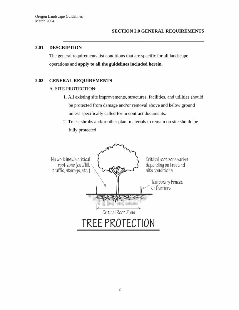
A. SITE PROTECTION:
1. All existing site improvements, structures, facilities, and utilities should
be protected from damage and/or removal above and below ground
unless specifically called for in contract documents.
2. Trees, shrubs and/or other plant materials to remain on site should be
fully protected
2
Oregon Landscape Guidelines March 2004
3
B. ENVIRONMENTAL CONDITIONS
1. Contractor should be responsible for controlling dust generated by
landscape construction activities during all phases of the landscape
project. Dust shall be minimized to the extent possible, using all
methods necessary, including but not limited to:
a. Sprinkling all exposed dust producing areas with water.
b. Applying Agency/Governmental approved dust control
measures on haul and access roads.
c. Establishing temporary vegetative cover.
d. Placing wood chips or other effective mulches on high vehicle
and equipment traffic areas
e. Maintaining adequate moisture control on all areas affected by
landscape activities.
f. Use of covered haul equipment.
g. Timing operations to periods of low wind.
2. Erosion Control and sediment control: Use of erosion prevention
techniques shall be emphasized over those of sediment control. All
erosion control methods must comply with state and local ordinances
a. Definitions:
(1.) Erosion prevention: techniques designed to protect soil
particles from the force of rain, wind and moving water.
(2.) Sediment control: measures designed to capture soil
particles after they have been dislodged and to attempt
their retention onsite.
b. Erosion Prevention: All construction projects shall include
properly installed, operated, and maintained temporary and
permanent erosion control measures.
(1.) Existing vegetation should be protected and left in
place.
(2.) Where existing vegetation has been removed, or
original grades disturbed, permanent erosion
Oregon Landscape Guidelines March 2004
4
prevention techniques shall be installed and
maintained.
(3.) Construction entrances: Vehicles or equipment shall
not access a worksite adjacent to a stream,
watercourse, storm or surface water structure/facility
or wetlands unless adequate measures are taken to
prevent physical erosion into water systems or
wetlands.
(4.) The use of approved sediment filters should be used as
temporary Catch Basin Protection on streets.
(5.) Plastic sheeting shall generally not be used for an
erosion control measure. It may be used for temporary
protection in small, highly erodable areas or on
temporary stockpiles of soil. Paths of concentrated
water flow from the plastic must be prevented.
3. Erosion prevention techniques: select methods as approved by
applicable regulations.
a. Surface erosion: areas best protected include all surface
disturbed but in particular, sites with slopes greater than 2% and
sites with highly erodable:
(1.) Use of cover crops should be used in areas where soil
surface will be exposed for long time periods, or
through wet periods. Materials used include oats,
wheat, annual rye-grass, and buckwheat. Should be
used in combination with temporary control measures.
(2.) Mulch sites with slopes less than 5%. Materials used
include straw, wood chips and shredded wood as
stipulated by applicable regulations. Mulch should be
placed 3 to 6 inches thick and needs periodic
replacement.
Oregon Landscape Guidelines March 2004
5
(3.) Hydromulching using water and tackifier or bonded
fiber mulches can be sprayed on areas for protection.
(4.) Erosion control blankets/mats may be used for slopes
up to 5%.
(5.) For slopes greater than 5% use slope retaining block or
rip-rap.
4. Sediment control techniques: select methods as approved by applicable regulations.
a. Situations not requiring sediment barriers:
(1.) Where there are no concentrated water flow and slope
to be protected is less than 2%.
(2.) Where flows are collected through the use of
temporary or permanent grading or other means that
direct flow and sediment to an approved settlement
pond, bioswale, filtering system, or sediment barrier.
(3.) Where there are no concentrated flows, slopes are less
than 10% and where the run-off moves through an
approved grass area that is at least as large as the
project area being drained.
(4.) Where the surface of the area is protected by approved
ground-cover or erosion control matting.
b. Sediment barrier types include straw bales, silt fences and mulch berms:
(1.) Straw bales: prone to washout over time use for short
term projects. Clear weeds and debris for a 2’ (two
foot) path along the area to be protected. Level the
surface so that bales make continuous contact with
ground. Lay bales end to end and stake with 2-3 foot
wood or metal stakes driven in 12” (twelve inches)
from ends of bales and down flush to top of bale.
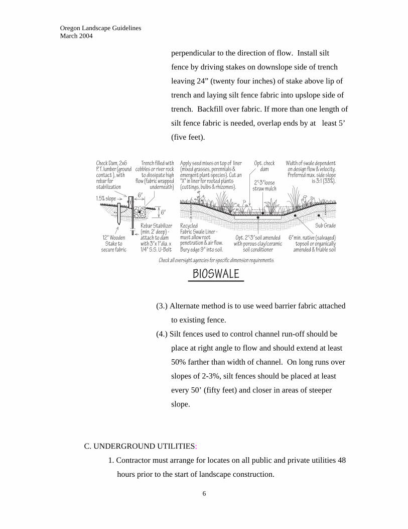
(2.) Silt fence: begin by clearing weeds and debris for a 2’
(two foot) path for silt fence. Second excavate a 12”
(twelve inch) wide and 6” (six inch) deep trench
Oregon Landscape Guidelines March 2004
perpendicular to the direction of flow. Install silt
fence by driving stakes on downslope side of trench
leaving 24” (twenty four inches) of stake above lip of
trench and laying silt fence fabric into upslope side of
trench. Backfill over fabric. If more than one length of
silt fence fabric is needed, overlap ends by at least 5’
(five feet).
(3.) Alternate method is to use weed barrier fabric attached
to existing fence.
(4.) Silt fences used to control channel run-off should be
place at right angle to flow and should extend at least
50% farther than width of channel. On long runs over
slopes of 2-3%, silt fences should be placed at least
every 50’ (fifty feet) and closer in areas of steeper
slope.
C. UNDERGROUND UTILITIES:
1. Contractor must arrange for locates on all public and private utilities 48
hours prior to the start of landscape construction.
6
Oregon Landscape Guidelines March 2004
7
2. Procedures for arranging locates:
a. Obtain the “ONE-CALL” number for the area
b. Call 48 hours prior to commencement of work.
c. Have the specific address and location of project on hand.
d. Identify type and extent of work
e. Indicate who is calling, contractor number, phone and address.
f. Provide construction starting dates and times.
3. Where utilities are marked and trenching or excavation must be
performed, marked areas should be carefully hand excavated to
determine exact alignment and depth prior to start of actual work.
4. Movement and/or removal of utilities should be carried out only by
properly licensed and trained companies.
5. Be aware of the APWA Uniform Color Code:
a White – proposed excavation.
b. Pink – Temporary Survey Markings
c. Red – Electric Power Lines, Cables, Conduit and Lighting Cables.
d. Yellow – Gas, Oil, Steam, Petroleum or Gaseous Materials.
e. Orange – Communication, Alarm or Signal Lines, Cables or Conduit.
f. Blue – Potable Water
g. Purple – Reclaimed Water, Irrigation and Slurry Lines.
h. Green – Sewer and Drain Lines
D. SAFETY
1. Landscape Contractor should exercise the necessary precautions to
protect the public, employees and real property during all phases of
landscape projects. All work should meet or exceed all national, state
and/or local regulations for human and environmental safety.
2. All equipment, tools, personal protective equipment, and operations
should conform to the Occupational Safety and Health Act (OSHA)
standards.
3. By law, the landscape business should have Material Safety and Data
Sheets (MSDS) on file at the business, in vehicles carrying materials
Oregon Landscape Guidelines March 2004
8
used on site and on the job site for any material that poses a risk to the
public and employees.
4. Employers and employees should have periodic safety training and
reviews, basic first aid training and CPR.
5. Employees should have and use Personal Protective Equipment as
needed for specific landscape operations including but not limited to:
hearing protection, eye protection, respiratory protection,
environmental protection (proper clothing), bodily protection such as
hard-hats, workboots and gloves.
6. Use of all pesticides (insecticides, herbicides, fungicides, rodenticides
etc.) must conform to current ODA licensing regulations and
manufacturers label regulations and recommendations.
7. Adequate barricades, flashers, signs and/or lights should be installed in
all hazardous locations including but not limited to areas of pedestrian
and vehicular traffic and open excavations.
8. All hazardous materials including, but not limited to, gasoline,
pesticides, and other similar materials should be stored in a safe and
protected manner in accordance with all applicable regulations.
9. All stacked materials including such items as lumber, pipe and similar
materials should be stacked and secured to prevent rolling and/or
spilling.
10. All work areas should be kept neat and tidy. Traffic areas should
remain clear and uncluttered. Hand tools should be stored in a manner
as to protect pedestrians from personal injury.
E. TOOLS & EQUIPMENT
1. Landscape Contractor is responsible for all equipment necessary to
perform the job.
2. Equipment should be safe, proper, efficient and suited to the job at
hand. All equipment should be maintained in proper, safe working
condition.

Oregon Landscape Guidelines March 2004
9
3. All employees operating equipment should have training prior to use
and should utilize equipment only for the jobs it is designed for.
4. All required safety devices and labels should be in place, in good
working order and should conform to OSHA regulations.
5. Equipment not in safe working order should be tagged and removed
from service until proper repairs are completed in conjunction with
safety regulations.
F. SITE CLEANUP
1. Landscape Contractor is responsible for reasonable cleanliness of job
site during all phases of work. Accumulation of all vegetative debris,
pots and other landscape construction debris should be removed from
the site on a regular basis and properly disposed of.
2. Upon completion of work, entire worksite should be inspected, all
walks and hard surfaces swept clean or properly washed off and all
debris/litter removed.
2.03 QUALITY ASSURANCE
A. REGULATORY REQUIREMENTS
1. Permits: it is the responsibility of the landscape contractor to ensure all
permits required in the performance of the contracted work have been
obtained.
2. Codes and Regulations: All work performed should comply with all
applicable codes, laws and regulations.
B. LICENSING: Landscape contractor and business must be properly licensed
and/or certified for all phases of work to be performed and must indicate
license numbers and types on all business materials for the job to be
performed.
C. TESTING
1. For systems and materials that require testing, the landscape contractor
shall ensure that arrangements have been made with the proper,
Oregon Landscape Guidelines March 2004
10
qualified inspectors to have tests made. Cost for testing will be paid by
the owner unless otherwise written into contract.
2. Materials and or work that fail to meet or exceed specified testing levels
should be corrected, removed from site or replaced at the expense of
the contractor or as specified by contract.
D. INSPECTIONS
1. A schedule of inspections should be agreed upon between the landscape
contractor and the owner or owner’s representative and written into the
contract.
2. Inspections required by any legal entities should be arranged for by the
contractor and inspection reports should be delivered to the owner or
owner’s representative.
2.04 REFERENCES: As required per individual section above.
2.05 SUBMITTALS
A. SHOP DRAWINGS: If required by contract, the landscape contractor should
submit shop drawings (illustrations of methods of construction) prior to or
during construction.
B. SAMPLES: Landscape contractor should provide samples of materials to
owner or owner’s representative prior to installation if required by contract.
C. PERMIT DOCUMENTS: Upon final completion of work, the contractor
should provide the owner with all approved and stamped drawings required for
permits and signed off permits.
D. AS-BUILT DRAWINGS: Upon completion of work, the contractor should
provide the owner with accurate drawings that reflect any changes made to
original plans and drawings if provided that indicate the as-built status of any
underground work.
Oregon Landscape Guidelines March 2004
11
E. EQUIPMENT MANUALS AND WARRANTIES: The contractor should
provide the owner with all manuals and warranty information for all equipment
installed on site.
2.06 SITE CONDITIONS
A. EXISTING CONDITIONS
1. Site Inspection:
Prior to commencement of work, contractor should be thoroughly
familiar with any surveys, investigative reports or covenants directly
related to the work to be performed. Related material should be
supplied to contractor by client or client’s representative.
a. Contractor should examine conditions at site, document all
conditions differing from those indicated in contract documents
and immediately notify client or client’s representative.
b. Underground obstructions such as, but not limited to, utilities,
structures, water, rock, hard pan, or other obstructions which are
not indicated on the plans or readily apparent should be treated
as additional work if encountered during construction. This
statement needs to be included in contracts.
2. Utilities:
a. Client or client’s representative should provide the contractor
with accurate as-built plans or drawings of existing underground
construction if available. Contractor should call for locates on
all jobs. The contractor should not be held responsible for
damages to underground utilities, other than those located,
unless provided with accurate as-built plans prior to the start of
construction.
b. Adequate point-of-connection for all water and other utilities
should be provided by the owner/client and installed by
properly licensed parties.
Oregon Landscape Guidelines March 2004
12
B. ENVIRONMENTAL REQUIREMENTS
1. Contractor should be aware of, and adhere to, any regulations protecting
air, water, plants, wildlife, and natural environmental features that may
be present on site.
2. Contractor should be aware of any regulations put forth by Public
agencies/authorities regarding dust, noise and/or water pollution.
2.07 SCHEDULING
Scheduling of start and completion dates should be agreed upon in written
contract. Changes to schedule need to be agreed upon by contractor and client or
client’s representative in writing.
2.08 SUBSTITUTIONS
All substitutions should only be allowed with written approval from contractor
and client or client’s representative.
2.09 WARRANTY
A. Contractor should be responsible for defective materials and faulty
workmanship while the work is in progress. Upon relinquishing care, custody
and control of a project, the contractor should be responsible for defective
materials and faulty workmanship for a minimum period of 90 days for plant
materials and one year for all other work.
B. Any damages to site improvements and facilities caused by the contractor’s
neglect should be corrected and paid for by the contractor at no cost to the
client.
C. After relinquishing care, custody, and control of a project, the contractor
should not be held responsible for the results of improper maintenance or
neglect.
D. At no time should the contractor be responsible for damages due to vandalism,
civil disorder, flood, earthquakes or other events beyond the contractors
control.
Oregon Landscape Guidelines March 2004
13
SECTION 3.0 - CONSTRUCTION LAYOUT
____________________________________________________________
3.01 DESCRIPTION
Construction layout establishes the actual positions of all control staking and
elements that are to remain and/or be placed in the landscape prior to the
commencement of work.
3.02 WORK INCLUDED
Section includes the accurate measurement, layout, and staking of both horizontal
and vertical points of all elements included on drawings as required for clearing,
grading, drainage, hardscapes, irrigation, lighting, and planting operations.
3.03 CONTRACTOR RESPONSIBILITY
A. Unless provided for in contract and written specifications, contractor should be
responsible for the accurate layout of all elements on the job site. The layout
of property lines, easements, and control points should be laid out by a
properly licensed land surveyor.
B. Contractor should be responsible for using all survey information furnished by
the client and should cross-check line and grade from adjacent bench marks of
staking to determine that existing survey and/or bench marks have not been
accidentally displaced.
C. Contractor should preserve all bench marks, survey stakes, survey control
points, reference points, and any other permanent points during construction.
Points damaged or removed should be replaced by a properly licensed
individual at the cost of the contractor.
D. Construction survey stakes which are displaced or destroyed by the
contractor’s operations should be replaced by a properly licensed individual at
the contractor’s expense.
Oregon Landscape Guidelines March 2004
14
3.04 STAKES
Stakes should be of wood or metal and of such length as to be clearly visible.
Stakes should be clearly marked as to purpose and measurement reference.
3.05 FLAGS
Flags should be brightly colored cloth or plastic and be able to withstand the
natural elements during the construction period.
3.06 LABELS
Labels should be of bright materials and should encircle plants and other
landscape elements marked for protection.
Oregon Landscape Guidelines March 2004
15
SECTION 4.0 - SITE PREPARATION/CLEARING
____________________________________________________________
4.01 DESCRIPTION
Clearing provides for the proper removal and disposal of designated site
improvements, vegetation, and debris prior to commencement of other
construction operations. Any such work should conform to all applicable local,
county, state and federal regulations.
4.02 WORK INCLUDED
Work includes the protection of all site improvements and plant materials to be
retained as outlined in section 2.02 – A, and it includes the removal of specified
structures, paving, and other existing improvements, plant material and debris.
4.03 EXISTING CONDITIONS
Prior to the commencement of clearing operations, the contractor should meet
with the client or client’s representative to designate all plant material and
existing site improvements to remain on site and those to be removed. To protect
both the consumer as well as the contractor, all preexisting conditions should be
documented in writing.
4.04 PROTECTIVE FENCING
Protective fencing or barriers should be wire, plastic or biodegradable mesh; solid
lumber; or similar material with a minimum 36” (thirty six inch) height.
4.05 PROTECTION OF EXISTING SITE IMPROVEMENTS AND PLANTINGS
Protect all improvements, the environment, and plantings as per section 2.02 -
GENERAL CONDITIONS - SITE PROTECTION. Also ensure all work
conforms to all applicable code requirements and restrictions.

Oregon Landscape Guidelines March 2004
16
4.06 CLEARING AND GRUBBING
A. Clearing and grubbing operations should begin only after protective fencing
and barriers have been installed. Protective measures should be maintained
throughout the duration of the project.
B. No grade changes should be made that will adversely impact root systems of
existing trees and shrubs that are to remain in project.
C. All undesirable stumps, major roots and debris should be removed in areas of
excavations.
D. All undesirable debris should be removed in areas of fill. Where fills are less
than five feet in depth, all stumps and root systems which would be buried
should be removed. In areas of fill greater than five feet stumps and roots
should be cut flush to original grade prior to burial.
E. In areas of no grade changes, all undesirable stumps and roots should be dug or
cut out to a depth of 18” (eighteen inches).
F. In areas where drainage systems are to be installed all stumps and roots should
be removed. Minimize compaction from the use of heavy equipment.
G. Backfill all stump, root and debris holes with suitable material in accordance
with fill and compaction requirements.
H. All noxious weeds and unwanted vegetation should be eradicated.
1. Use of herbicides should be performed or supervised directly by a
properly trained, certified individual. All such work should conform to
current ODA licensing regulations.
2. Selection of methods should be based on Integrated Pest Management
principles using least toxic methods to accomplish the goal and should
conform to all applicable legal and environmental regulations.
I. Contaminated soils: soils containing hazardous or unstable materials that are
encountered, should be reported to the proper authorities and should be
removed to a certified hazardous waste disposal facility as prescribed by law.
Oregon Landscape Guidelines March 2004
17
4.07 DISPOSAL
A. All cleared site improvements, vegetation and debris.
1. Vegetative matter; non-diseased and non-contaminated
a. Can be ground up and used on site but not used as a soil
ammendment.
b. If removed, should be legally disposed of.
2. Diseased or insect-infested vegetation should be disposed of by
burning, burial, or other disposal methods as set forth per Oregon
Department of Agriculture, governmental and/or environmental
regulations.
B. Burning or burying on site should only be performed in a legal manner
conforming to all regulations. Large woody material should be ground up prior
to burial. No onsite burning or burial should occur without permission of
client or client’s representative.
Oregon Landscape Guidelines March 2004
18
SECTION 5.0 - SITE PREPARATION - GRADING
____________________________________________________________
5.01 DESCRIPTION
Grading involves the changing of existing elevations and topography of a site to
provide positive drainage where needed and to allow for the construction and
installation of landscape improvements.
5.02 WORK INCLUDED
Work includes rough grading, import and export of soils, excavation and
embankment fills, compacting, topsoil placement, and finish grading.
5.03 QUALITY ASSURANCE
When required by regulation or written specification, testing of compacted fill,
import soil and/or exiting soil conditions should be done by a certified testing
laboratory or company.
5.04 SITE CONDITIONS
A. EXISTING CONDITIONS
1. Prior to the commencement of any grading work the contractor should
be aware of and implement proper precautionary measures for any and
all hazards that may impact pedestrians, workers, environment and/or
vehicles as per section 2.02. D.
2. As per section 2.02 General Requirements, all existing improvements
should be properly protected for safety and damage during grading
operations.
B. Contractor should be aware of consequences of grading practices and the
effects it will have on surrounding structures, pedestrian areas and existing
landscapes.
C. Avoid causing damage to existing plant root-zones.

Oregon Landscape Guidelines March 2004
19
5.05 CONTRACTOR RESPONSIBILITY
A. Any damage, such as compaction or rutting, caused on existing grades during
grading operations should be repaired and returned to the original condition.
B. Settlement or erosion that occurs during grading operations should be repaired
and grades reset to the required elevations and contours.
5.06 FILL SOIL MATERIAL
A. Fill soil should be of comparable composition to soil exiting on site and should
be free of rocks larger than three inches in diameter, vegetation and other
debris.
B. Where excavation areas yield material that is mostly rock or gravel, such
material may be use only as fill in areas where it will be buried three or more
feet deep. Such material should not be used any closer to the surface unless
designated in specifications, by the client or the client’s representative
C. An on-site source of additional soil needed to balance the grading operations
may, when appropriate, be designated by the client or client’s representative.
D. All imported soil should be free of diseases, pests, debris, contaminants and
noxious weeds.
5.07 TOPSOIL
A. All imported topsoil should be natural soil, or an approved planting mix with
soil, graded to not larger than ¾ inch and should be free of un-decomposed
animal or vegetable matter, diseases, pests and noxious weeds unless otherwise
specified.
B. The interface of existing soil and added topsoil should be tilled or scarified
when conditions warrant to break up transition layers.
5.08 SLOPE RATIOS
A. The maximum slope ratio in cut situations should not exceed two to one (2:1),
measured horizontal to vertical unless approved by a permitting agency with
licensed engineer review.
Oregon Landscape Guidelines March 2004
20
B. The maximum slope ratio for fill situations should not exceed three to on (3:1),
measured horizontal to vertical.
5.09 ROUGH GRADING
A. GRADE TOLERANCES: All rough grading should be carried out to an
accuracy of plus or minus two-tenths (.2) of a foot from designed and/or
specified elevations. Pockets or depressions in graded surfaces should be
eliminated.
B. Grades should be finished with a smooth natural appearance and should blend
evenly into exiting areas. Rough graded areas should be free of rocks, large
clods of dirt, unspecified mounds or ridges and any debris.
C. All grades, both cut and fill, have to meet the original grade within the
boundaries of the construction project or the property boundaries whichever
applies.
5.10 FILL AND COMPACTION
A. All vegetative matter should be removed from surfaces where fill will be
placed and the surface should be scarified and smoothed prior to the addition
of fill.
B. Where fills of a different soil type are to be made on slopes, the surface of the
area to be filled needs to be tilled scarified
C. In situations where fill is to be placed on slopes with a ratio greater than three
to one (3:1), the work should be approved by a properly licensed individual or
permitting agency.
D. Fill soil should be placed in layers 6-8” (six to eight inches) thick and
compacted as they are laid. The first layer should be placed and incorporated
into the existing surface
E. Cut and fill areas should be kept shaped throughout the construction process
and surface drainage patterns should be maintained. Areas of cut and fill
should be protected from run-off and erosion. When grading and weather
protection is not practical, sediment control measures should be in place.
Oregon Landscape Guidelines March 2004
21
F. Compaction of fill material should only be done when the fill material has
adequate moisture content for the material to compact properly. Compaction
should not take place in soils with excessive moisture or in rain unless
authorized by proper permitting agencies.
G. Minimum degrees of compaction:
1. Top one foot under walks or paving: ..................95% relative density
2. Other fill under walks and paving: .....................90% relative density
3. Fill in planting areas: ..........................................80% relative density
4. Other non-structural fill or backfill:....................85% relative density
5.11 TOPSOIL PLACEMENT
Placement of imported topsoil, if required, should take place prior to finish grading.
5.12 FINISH GRADING
A. Finish graded surfaces should be smooth, uniform and free of debris. No rocks
or clods over ¾” (three quarter inch) should remain for lawn areas, 2” (two
inches) or over for planting areas.
B. All grades should blend smoothly into existing grades.
C. Finish grades abutting structures or hardscapes should be even, uniform and at
heights specified by code or written specifications.
D. All finish grades should slope away from improvements at a minimum 2%
slope to an approved drainage way.
Oregon Landscape Guidelines March 2004
22
SECTION 6.0 – SITE PREPARATION – DRAINAGE
____________________________________________________________
6.01 DESCRIPTION
Sub-surface drainage systems collect water from the surface and from under ground on a
site and deposit the water in an area where it can be absorbed into the ground or treated in
a natural bioswale or storm water treatment pond. Surface drainage includes sheet
drainage across the ground surface and the use of drainage swales. All work should
conform to all applicable local, county, state or federal regulations
6.02 WORK INCLUDED
Work includes the installation of surface and sub-surface drainage systems and water
collection devices.
6.03 QUALITY ASSURANCE
All work will be performed to the standards set by code and regulating agencies and at a
minimum will be performed to the level set herein.
6.04 SUBMITTALS
Some projects and permitting requirements may require shop and as-built drawings. It
will be the responsibility of the contractor to obtain and/or provide this information.
6.05 EXISTING CONDITIONS
All exiting improvements and plantings that will remain in project should be properly
protected and maintained in the construction of drainage systems. Contractor should be
responsible for repair and replacement of any damages caused by neglect or construction
operations at the contractor’s expense.
6.06 GENERAL/ PRODUCTS
All products used in drainage systems shall be new and of the type specified by any
applicable codes or regulations as regards to type and size. Gravel and rock used in
Oregon Landscape Guidelines March 2004
23
drainage systems should be clean and of sizes indicated by code or regulation or drainage
system manufacturer specification.
6.07 DRAINAGE PIPE
A. Drainage pipe should be any material listed as suitable by its ASTM number as
being suitable for subsurface landscape drainage applications and meeting
those requirements set forth by any codes or regulations.
B. Types of drainage systems include, but are not limited to, corrugated and
smooth wall plastic, and coextruded dual wall corrugated plastic pipe;
prefabricated plastic and geotextile fabric and geocomposite subsurface
interceptor drains.
C. All fittings used in drainage systems should either match, or be compatible
with the materials as listed above in section “B.”.
6.08 MATERIAL STORAGE
All pipe and fittings should be stored in a manner that will protect materials from
mechanical damage and from long terms exposure to the affects of UV rays. Piping
should be stored as to prevent sagging and distortion. Storage of piping should conform
to OSHA and any other applicable regulations.
6.09 INSTALLATION REQUIREMENTS: GENERAL
A. All open excavations should have barricades, equipped with flashing lights
that operate in times of limited light and/or darkness, and flagging. Barricades
need to be installed in compliance with OSHA regulations.
B. No drainage system should be backfilled until it can be confirmed that all
piping and connections can be installed at the locations and slopes needed for
positive drainage to approved outlet sites.
C. All drainage systems should be laid true to line and grade. When all parts of
the drainage system are laid, the system should have a smooth, continuous flow
line with a minimum of a 1% (one percent) grade.
Oregon Landscape Guidelines March 2004
24
D. Trench bottoms and backfill should be formed and laid to provide even support
to a minimum of one fourth of the pipe circumference along the entire length
of the drain system.
E. All ends/outlets of drainage systems should be so constructed as to prevent
erosion and be fully protected from the entry of soil, debris or animals. During
the construction work, interiors of systems should be kept free of soil and
flushed clean.
F. All drainage systems used should collect and dispose of water in a manner that
protects waterways from sediment and pollution in compliance with code and
environmental regulations.
G. Test drain as described in 6.13.B.
6.10 SURFACE DRAINAGE
A. SYSTEM DESCRIPTION: Surface drainage systems use the contouring or
topography of the finished grade to collect and direct the flow of surface water
to approved outlets or collection areas utilizing sheet drainage and swales.
B. FLOOD AND DAMAGE PREVENTION: Surface drainage should be
installed and directed to prevent flooding and damage to site improvements.
C.MINIMUM SLOPES: All buildings and site improvements should have a
minimum of a 2% (two percent) surface slope away from them.
D.RESTRICTIONS ON OFF-SITE FLOW
No surface drainage systems shall increase water flow off the site or property.
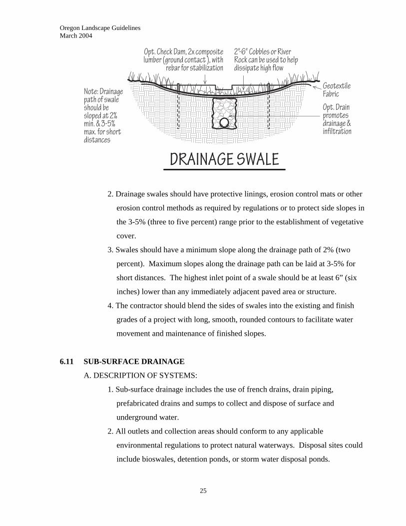
E. DRAINAGE SWALES:
1. Need to direct water to approved outlet or collection sites such as, but not
limited to, bioswales, stormwater detention ponds, or in ground sumps.
Oregon Landscape Guidelines March 2004
2. Drainage swales should have protective linings, erosion control mats or other
erosion control methods as required by regulations or to protect side slopes in
the 3-5% (three to five percent) range prior to the establishment of vegetative
cover.
3. Swales should have a minimum slope along the drainage path of 2% (two
percent). Maximum slopes along the drainage path can be laid at 3-5% for
short distances. The highest inlet point of a swale should be at least 6” (six
inches) lower than any immediately adjacent paved area or structure.
4. The contractor should blend the sides of swales into the existing and finish
grades of a project with long, smooth, rounded contours to facilitate water
movement and maintenance of finished slopes.
6.11 SUB-SURFACE DRAINAGE
A. DESCRIPTION OF SYSTEMS:
1. Sub-surface drainage includes the use of french drains, drain piping,
prefabricated drains and sumps to collect and dispose of surface and
underground water.
2. All outlets and collection areas should conform to any applicable
environmental regulations to protect natural waterways. Disposal sites could
include bioswales, detention ponds, or storm water disposal ponds.
25
Oregon Landscape Guidelines March 2004
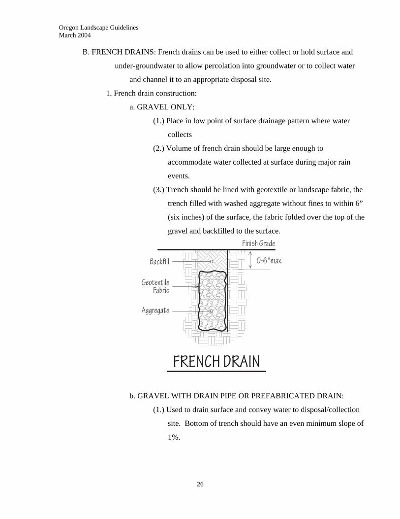
B. FRENCH DRAINS: French drains can be used to either collect or hold surface and
under-groundwater to allow percolation into groundwater or to collect water
and channel it to an appropriate disposal site.
1. French drain construction:
a. GRAVEL ONLY:
(1.) Place in low point of surface drainage pattern where water
collects
(2.) Volume of french drain should be large enough to
accommodate water collected at surface during major rain
events.
(3.) Trench should be lined with geotextile or landscape fabric, the
trench filled with washed aggregate without fines to within 6”
(six inches) of the surface, the fabric folded over the top of the
gravel and backfilled to the surface.
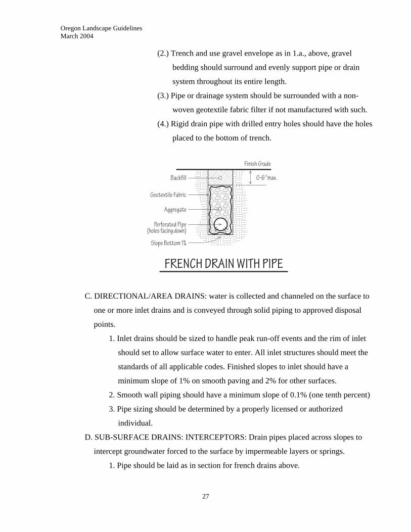
b. GRAVEL WITH DRAIN PIPE OR PREFABRICATED DRAIN:
(1.) Used to drain surface and convey water to disposal/collection
site. Bottom of trench should have an even minimum slope of
1%.
26
Oregon Landscape Guidelines March 2004
(2.) Trench and use gravel envelope as in 1.a., above, gravel
bedding should surround and evenly support pipe or drain
system throughout its entire length.
(3.) Pipe or drainage system should be surrounded with a non-
woven geotextile fabric filter if not manufactured with such.
(4.) Rigid drain pipe with drilled entry holes should have the holes
placed to the bottom of trench.
C. DIRECTIONAL/AREA DRAINS: water is collected and channeled on the surface to
one or more inlet drains and is conveyed through solid piping to approved disposal
points.
1. Inlet drains should be sized to handle peak run-off events and the rim of inlet
should set to allow surface water to enter. All inlet structures should meet the
standards of all applicable codes. Finished slopes to inlet should have a
minimum slope of 1% on smooth paving and 2% for other surfaces.
2. Smooth wall piping should have a minimum slope of 0.1% (one tenth percent)
3. Pipe sizing should be determined by a properly licensed or authorized
individual.
D. SUB-SURFACE DRAINS: INTERCEPTORS: Drain pipes placed across slopes to
intercept groundwater forced to the surface by impermeable layers or springs.
1. Pipe should be laid as in section for french drains above.
27
Oregon Landscape Guidelines March 2004
28
2. Depth should be set to properly intercept water.
E. SUB-SURFACE DRAINS: Systems used to collect water from poorly drained area or
used to drain entire areas.
1. Pattern types: random, herringbone, gridiron.
2. Pipe size to drain a particular area depends on gradient to outlet and on peak
run-off. Design of system should be by manufactures standards and/or as
performed/permitted by properly licensed/authorized individuals.
3. Depth and spacing: Depth is governed by outlet elevation. All drainage piping
should be laid to prevent frost damage. Spacing is determined by soil type.
General applications for recreational turf:
F. PREFABRICATED DRAIN SYSTEMS:
1. Install as per manufacturer’s standards; normally with 3-4” (three to four inch)
wide trenches with a minimum 12” (twelve inch) depth.
2. Trenches should have minimum 1% bottom slope to outlet
3. No envelope required.
4. Maximum length of laterals 50’ (fifty feet) unless size of drain is increased.
5. Sub-main collectors should not exceed 100’ in length.
6. Main collectors should be sized to handle maximum flows.
6.12 FINAL GRADING AND TESTING
A. FINISH GRADES: Finished grades adjacent to drainage systems should allow for
positive flow into inlets with no standing water.
B. TESTING AND FLUSHING: Upon completion of systems, all portions should be
flushed to clear all debris and confirm positive flow of water through systems.
Oregon Landscape Guidelines March 2004
29
7.0 HARDSCAPES - WOOD CONSTRUCTION
____________________________________________________________
7.01 DESCRIPTION
Wood construction allows for the development of circulation and outdoor use areas,
privacy and screening, terracing and the demarcation of edges on the ground. It is used
for both functional and aesthetic purposes.
7.02 WORK INCLUDED
Section 7.0 includes the construction of fences, decks, garden stairs and paths, benches,
arbors, retaining walls, planter boxes, header boards and other wooden structures.
7.03 QUALITY ASSURANCE
A. It will be the responsibility of the contractor to ensure all necessary permits have been
obtained; to use materials that meet all code requirements and specifications; and to
use construction techniques that meet codes and protect the clients’ welfare.
B. All lumber used should be of a grade that meets code, specification and contract
requirements. Lumber grades should be those as given by the following associations:
1. Fir/Hemlock: Western Wood Products Association
2. Cedar: Western Wood Products Association
3. Redwood: California Redwood Association/Redwood Inspection Association
4. Pressure Treated Lumber: American Wood Preservers Bureau
5. Plywood: American Plywood Association
C. All lumber should conform to appearance and finish required by code specification,
and contract.
7.04 SCHEDULING
All grading, underground utility, irrigation piping and protective sleeves that are to occur
where structures in this section are to be built, should be completed prior to the beginning
of wood construction.
Oregon Landscape Guidelines March 2004
30
7.05 LUMBER PRODUCTS AND MATERIALS
A. LUMBER TYPES:
1. DOUGLAS FIR AND HEMLOCK: Used in outdoor situations for both
structural and appearance purposes. These should be painted, stained or
treated for weather exposure and should not be used in direct ground or water
contact. Depending on application, these may have smooth or rough-sawn
surfaces.
2. WESTERN RED CEDAR/ALASKAN YELLOW CEDAR/PORT ORFORD
CEDAR:
Used primarily for appearance and non-structural purposes. May be used in
limited structural situations with relatively light loads (check building codes
and practices). Cedar lumber may be used unfinished or can be painted with
exterior grade paints and/or stains, or treated for weather exposed purposes. It
may have rough sawn or smooth surfaces. “All heartwood” grade may be used
for ground contact with limited life span.
3. REDWOOD: Used primarily for appearance and non-structural uses. May be
used in limited structural situations with relatively light loads (check building
codes and practices). Redwood lumber may be used unfinished or can be
painted with exterior grade paints and/or stains, or treated for weather exposed
purposes. Redwood may be used for direct ground contact or within 12”
(twelve inches) of grade, if it is “All heartwood” grade.
4. SPRUCE: Limited use, generally for fence boards. Should be painted or stained
for weather exposure.
5. TREATED LUMBER: Lumber that has been treated with chemical
preservatives to prevent insect and fungal damage.
a. Lumber treated with creosote or pentachloraphyenol (“Penta”) should
not be used.
b. All weather treated wood: treated with copper salts and arsenate, wood
used for wet weather conditions. Should not be used for ground
contact. Can be structural or finish lumber.
Oregon Landscape Guidelines March 2004
31
c. Ground contact lumber: Deep treated to withstand ground and water
contact and used primarily for structural applications.
d. SAFETY PRECAUTIONS WITH TREATED LUMBER
(1.) Avoid prolonged skin contact.
(2.) Wear gloves and long sleeve shirts when handling.
(3.) Wear approved dust mask and eye protection when cutting.
(4.) Wash hands thoroughly after handling.
(5.) Do not burn; dispose of properly in a hazardous material
collection site.
6. COMPOSITE PLASTIC/WOOD MATERIALS: Used in place of surface and
appearance lumber applications. Materials are weatherproof and may not need
additional finishes. Not approved for structural applications. Use as per
manufacturer’s specifications.
B. SEASONING: To prevent warping and other problems, lumber should indicate that it
has been air-dried or kiln dried to a moisture content of 19% or less. Grade stamps will
indicate the proper dryness with marks of “DRY”, “S-DRY”, “MC-15”, or “KILN-
DRIED”. Lumber stamped as “GRN” or “S-GRN” should not be used in exterior
applications.
C. SIZING: All lumber should conform to the sizes and finishes as specified in permits,
codes and/or specifications. The dimension size of lumber should be used in all
calculations and measurements.
D. FASTENERS AND JOINING:
1. All exposed fasteners including nails, screws, lag screws, bolts, hinges, latches
or other fasteners should be galvanized, non-corrosive metal or have non-
corrosive finishes.
2. All fasteners should be sized and used as per code or specification to provide
secure, safe connections.
3. Nails, bolts, and screws should be placed in positions far enough from the
edges of lumber piece to prevent splitting. Screw, lag screws, and bolts should
have properly sized pilot holes drilled to proper depths prior to fastening.
Oregon Landscape Guidelines March 2004
32
E. CONNECTORS: Non-corrosive connectors; selected, sized and placed to meet code
and/or specifications, should be used for beams, joists, ledgers, rafters and posts when
called for in design or specifications.
F. WOOD FINISHES:
1. PROTECTION: Wood, other than redwood or cedar, should have a protective
finish to prevent excessive cupping, checking, warping and/or splitting.
2. TYPES: Finish products include water repellents, water or oil base stains and
paints, and specific wood preservatives. Apply as per manufacturers’
specifications.
G. CONCRETE: All concrete used in the installation of piers, footings, or below grade
posts in wood construction should be the equivalent of a “5-sack” mix.
H. PIER BLOCKS:
1. Precast pier blocks can be notched, flat, or have metal post/beam connectors
poured as an integral part of the block. Blocks with lumber inset in concrete
for fastening should not be used.
2. Pier blocks can be set on gravel or concrete footing. The elevation of the pier
block, above finish grade, should provide a minimum ground clearance for
non-ground contact lumber of 6” (six inches).
3. Footings for pier blocks should have their base below frost line and should be
compacted properly to deter settling over time.
I. FLASHING: Non-Corrosive metal flashing material should be used to provide insect
and decay protection whenever wood construction is in contact with existing
structures.
7.06 LAYOUT
The exact location of each wood construction element should be accurately established
and marked on-site prior to the start of construction to assure proper alignment.
7.07 LUMBER STORAGE
Lumber stored on site should have weather protection, stacked flat with adequate support
to prevent bending and should not have ground contact.
Oregon Landscape Guidelines March 2004
33
7.08 GENERAL WOOD CONSTRUCTION PRACTICES
A. All joint should be made accurately and fastened securely. The type of joint used will
be determined by code or specification. Any lumber with splitting due to improper
joining and fastening should be replaced at contractor’s expense.
B. Splices in beams, joists, rails or similar elements should only occur over supporting
members.
C. All posts below grade, or all supporting members on grade or within 6” (six inches) of
grade, should be approved for ground contact.
D. All wood surfaces, except where specifications or design call for unfinished lumber,
should be sealed with an appropriate wood finish product applied to the
manufacturer’s specifications.
7.09 FENCE CONSTRUCTION
A. DESCRIPTION: Fences can be freestanding or attached fences and screens.
B. LUMBER GRADES:
1. POSTS: Posts should be ground contact grade pressure treated wood or “All
Heart” grade cedar or redwood.
2. RAILS: Rails can be pressure treated lumber; standard and better or higher
grade of Douglas fir/hemfir; or cedar or redwood in “All Heart” or select
grades.
3. FENCE BOARDS: Boards should have a nominal thickness of 1” (one inch)
and a dimension thickness of not less than ¾” (three quarter inch). They should
be an appearance grade free of defects.
C. LOCATION: Placement of fences and screens should comply with all code and permit
requirements. When placed on the property line they become community property.
The client should have written agreements with the owners of neighboring properties
when so placing fences and screens.
D. FENCE HEIGHT: Fence height will vary according to use, application and code
requirements. It is the responsibility of the contractor assure fence heights meet codes.
Generally, a 6’ (six foot) height is the maximum allowable height without code
variance.
Oregon Landscape Guidelines March 2004
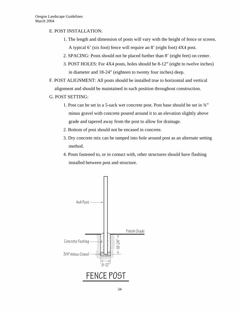
E. POST INSTALLATION:
1. The length and dimension of posts will vary with the height of fence or screen.
A typical 6’ (six foot) fence will require an 8’ (eight foot) 4X4 post.
2. SPACING: Posts should not be placed further than 8’ (eight feet) on center.
3. POST HOLES: For 4X4 posts, holes should be 8-12” (eight to twelve inches)
in diameter and 18-24” (eighteen to twenty four inches) deep.
F. POST ALIGNMENT: All posts should be installed true to horizontal and vertical
alignment and should be maintained in such position throughout construction.
G. POST SETTING:
1. Post can be set in a 5-sack wet concrete post. Post base should be set in ¾”
minus gravel with concrete poured around it to an elevation slightly above
grade and tapered away from the post to allow for drainage.
2. Bottom of post should not be encased in concrete.
3. Dry concrete mix can be tamped into hole around post as an alternate setting
method.
4. Posts fastened to, or in contact with, other structures should have flashing
installed between post and structure.
34
Oregon Landscape Guidelines March 2004
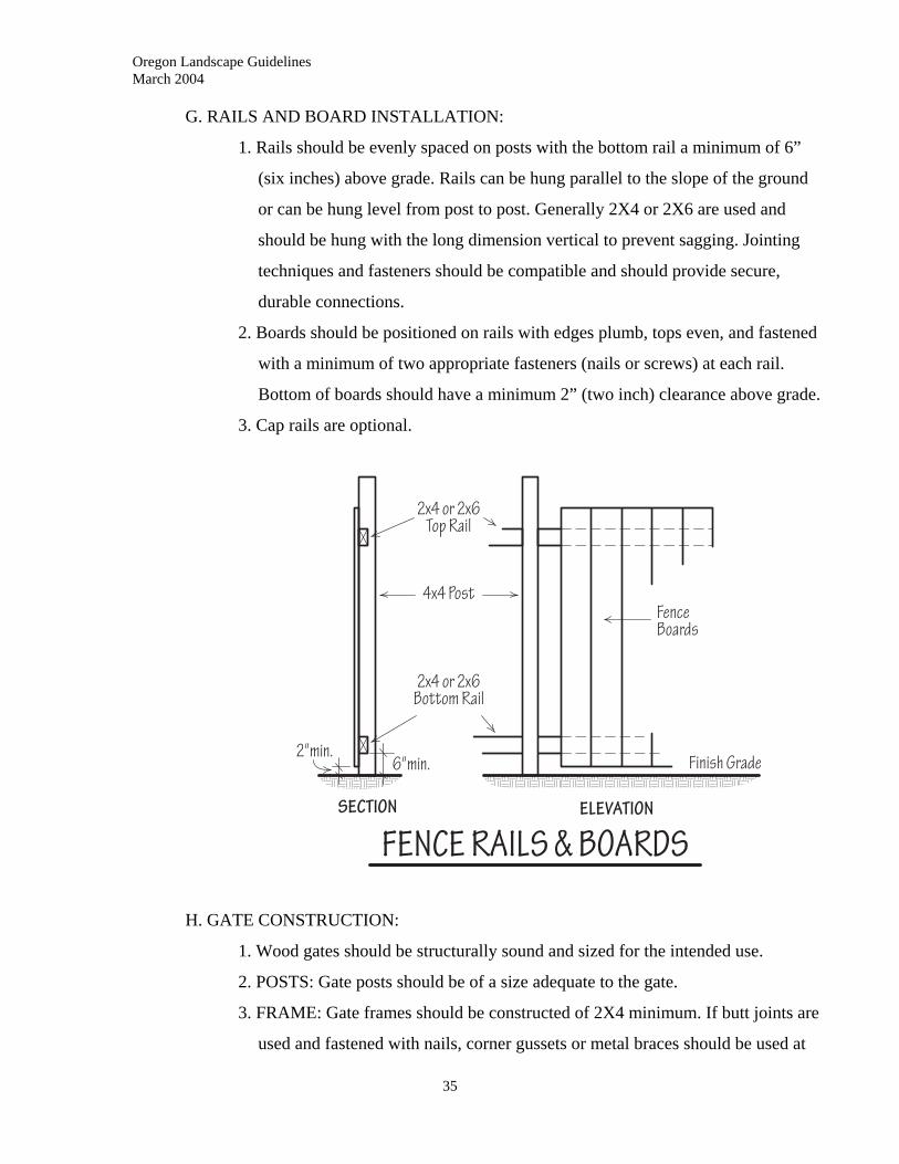
G. RAILS AND BOARD INSTALLATION:
1. Rails should be evenly spaced on posts with the bottom rail a minimum of 6”
(six inches) above grade. Rails can be hung parallel to the slope of the ground
or can be hung level from post to post. Generally 2X4 or 2X6 are used and
should be hung with the long dimension vertical to prevent sagging. Jointing
techniques and fasteners should be compatible and should provide secure,
durable connections.
2. Boards should be positioned on rails with edges plumb, tops even, and fastened
with a minimum of two appropriate fasteners (nails or screws) at each rail.
Bottom of boards should have a minimum 2” (two inch) clearance above grade.
3. Cap rails are optional.
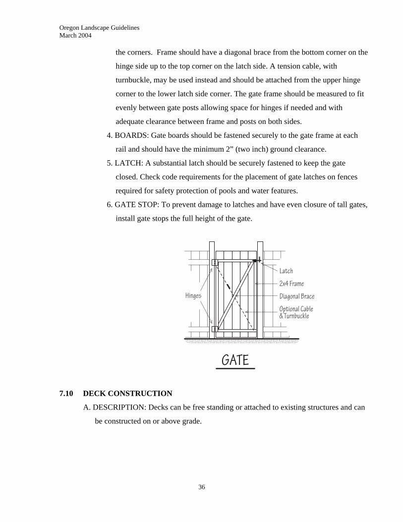
H. GATE CONSTRUCTION:
1. Wood gates should be structurally sound and sized for the intended use.
2. POSTS: Gate posts should be of a size adequate to the gate.
3. FRAME: Gate frames should be constructed of 2X4 minimum. If butt joints are
used and fastened with nails, corner gussets or metal braces should be used at
35
Oregon Landscape Guidelines March 2004
the corners. Frame should have a diagonal brace from the bottom corner on the
hinge side up to the top corner on the latch side. A tension cable, with
turnbuckle, may be used instead and should be attached from the upper hinge
corner to the lower latch side corner. The gate frame should be measured to fit
evenly between gate posts allowing space for hinges if needed and with
adequate clearance between frame and posts on both sides.
4. BOARDS: Gate boards should be fastened securely to the gate frame at each
rail and should have the minimum 2” (two inch) ground clearance.
5. LATCH: A substantial latch should be securely fastened to keep the gate
closed. Check code requirements for the placement of gate latches on fences
required for safety protection of pools and water features.
6. GATE STOP: To prevent damage to latches and have even closure of tall gates,
install gate stops the full height of the gate.
7.10 DECK CONSTRUCTION
A. DESCRIPTION: Decks can be free standing or attached to existing structures and can
be constructed on or above grade.
36
Oregon Landscape Guidelines March 2004
37
B. CONTRACTOR RESPONSIBILITY:
1. Contractor should make sure any needed permits are obtained and posted, and
should ensure that all work meets or exceeds all applicable codes or
specifications.
2. For decks over 30” (thirty inches) above grade or for decks with any unusual
loading, design of structural members should be carried out by a properly
licensed individual.
3. Flashing should be used at any point where parts of a deck contact existing
structures.
C. LUMBER GRADES:
1. Posts, beams, joists or stringers that will have ground contact or be within 8”
(eight inches) of grade should be graded for ground contact.
2. All structural members should be built of lumber graded for structural use and
should have a grade of standard and better or higher.
3. Decking and finish work such as rail balusters should be finish and/or
appearance grades.
D. PIERS:
1. TYPES: Piers can be poured in place concrete or precast pier blocks on a
gravel footing. On-grade decks can have sleepers laid on existing slabs or a
compacted gravel base. Deck design, soil type and codes will determine the
necessary pier construction.
a. Poured wet concrete piers should be a minimum of 12” (twelve inches)
in diameter, and should extend below the frost line. Tops of piers
should have non-corrosive metal post or beam brackets inset into wet
concrete, plumbed and aligned to deck structure.
Oregon Landscape Guidelines March 2004
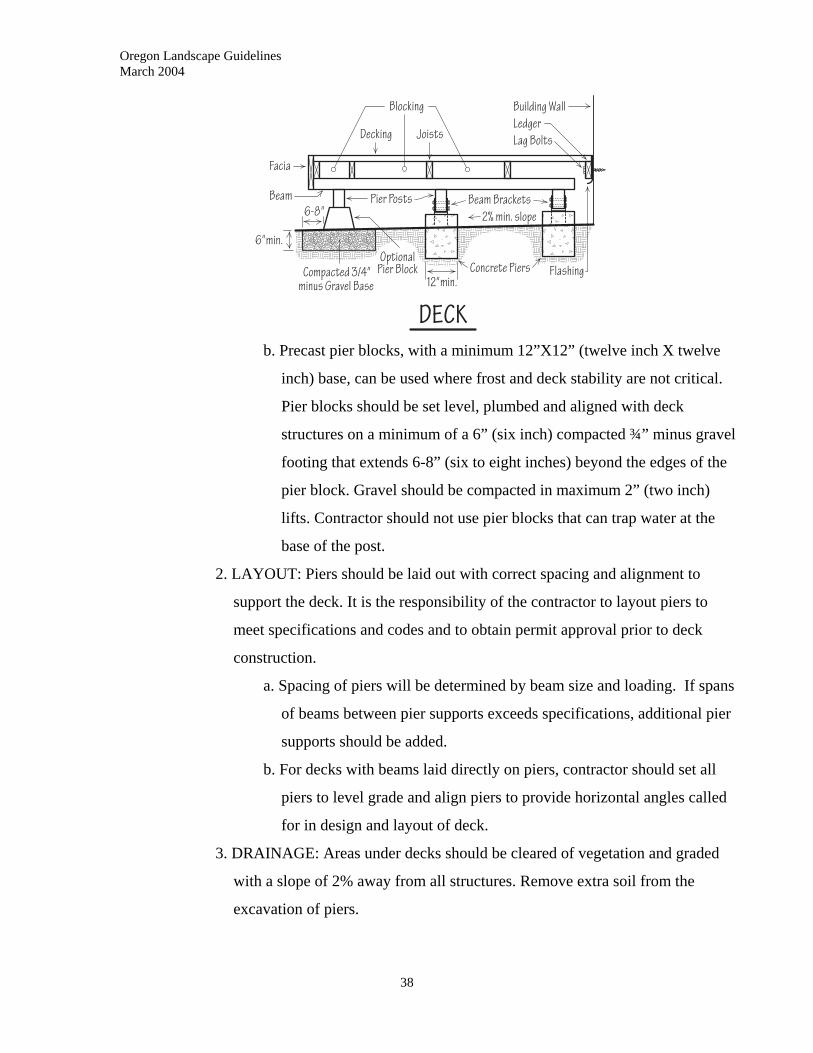
b. Precast pier blocks, with a minimum 12”X12” (twelve inch X twelve
inch) base, can be used where frost and deck stability are not critical.
Pier blocks should be set level, plumbed and aligned with deck
structures on a minimum of a 6” (six inch) compacted ¾” minus gravel
footing that extends 6-8” (six to eight inches) beyond the edges of the
pier block. Gravel should be compacted in maximum 2” (two inch)
lifts. Contractor should not use pier blocks that can trap water at the
base of the post.
2. LAYOUT: Piers should be laid out with correct spacing and alignment to
support the deck. It is the responsibility of the contractor to layout piers to
meet specifications and codes and to obtain permit approval prior to deck
construction.
a. Spacing of piers will be determined by beam size and loading. If spans
of beams between pier supports exceeds specifications, additional pier
supports should be added.
b. For decks with beams laid directly on piers, contractor should set all
piers to level grade and align piers to provide horizontal angles called
for in design and layout of deck.
3. DRAINAGE: Areas under decks should be cleared of vegetation and graded
with a slope of 2% away from all structures. Remove extra soil from the
excavation of piers.
38
Oregon Landscape Guidelines March 2004
39
4. PIER POSTS: Posts should be sized to meet deck design, loading, and code.
Posts that come within 6” (six inches) of finish grade should be approved for
ground contact. Pier posts should be connected to piers with approved
connectors.
5. CROSS BRACING: For decks over 4’ (four feet) in height and decks carrying
more load than pedestrian traffic and deck furniture, cross bracing should be
used from joist/beams to posts to prevent lateral movement and swaying.
Braces should be installed to code.
E. BEAMS AND JOISTS:
1. BEAM CONSTRUCTION: Post and beam or drop beam construction may be
used. Beams may be single or composite members. Beam tables or
specifications from a properly licensed individual should be use to properly
size beams. Beam spacing will be determined by allowable joist spans and
spacing.
2. LUMBER AND FASTENING:
a. Lumber should be structural type and grade. Beams should be securely
fastened to posts and ledgers with non-corrosive hangers or bolts.
3. BEAM LAYOUT: Beams should be laid out over posts, set level, or with a 1%
cross slope away from structures if called for.
4. JOIST SIZE AND SPACING:
a. Joists are used to support deck flooring.
b. Joist sizes are set by the support beam spacing and should be
determined from deck tables or as designed by a properly licensed
individual.
c. Joist spacing is determined by the strength of the decking material used.
Generally, joist spacing should not exceed 24” (twenty four inches) for
2” (two inch) thick decking and should not exceed 12” (twelve inches)
for 1” (one inch) thick decking.
d. JOIST PLACEMENT: Joists can be set on top of beams or hung from
beams to meet design requirements. Joists should be fastened to beams
with code approved methods.
Oregon Landscape Guidelines March 2004
40
e. JOIST BLOCKING: Deck joist should be supported laterally to prevent
twisting. Blocking, either metal or wood, members the same size as the
joist should be placed between joists at 6-8’ (six to eight foot) intervals
along the length of the joists.
F. LEDGER BOARDS:
1. Used to support the end of joists in place of a beam when a deck is attached to
an existing structure and the joists run perpendicular to the structure’s wall.
a. Ledger board has to be set at an elevation so that water cannot enter
over door sills when decking is in place.
b. Siding where ledger attaches to structure should be removed. It is best if
ledger is fastened to the rim joist of the wall; second best is attachment
to the wall studs.
c. Ledgers are 2” (two inch) thick lumber with the width matching the
joists.
d. Flashing should be placed between the ledger and the wall and/or over
the ledger to provide moisture protection to the structure.
e. Fasten ledgers to structure with 3/8” (three eighths inch) lag screws that
penetrate the rim joists or studs 2/3 of their thickness.
G. DECK FLOORING:
1. Decking can be douglas fir, cedar, redwood or composite lumber.
2. Decking should be laid with the bark side up to prevent cupping and the pulling
loose of fasteners.
3. Decking should be laid with a minimum of 1/8” (one eighth inch) space
between boards. Wet lumber should be laid tight to allow for shrinkage.
4. Decking should be fastened with two twelve-penny galvanized nails or deck
screws over each joist or support member.
5. Fasteners should be placed in from edges and end of lumber a sufficient
distance to prevent splitting.
H. DECK TRIM:
1. Position of fascia to be determined by layout and design of beams and joist.
2. Fascia can cover decking ends or decking can be cantilevered over fascia.
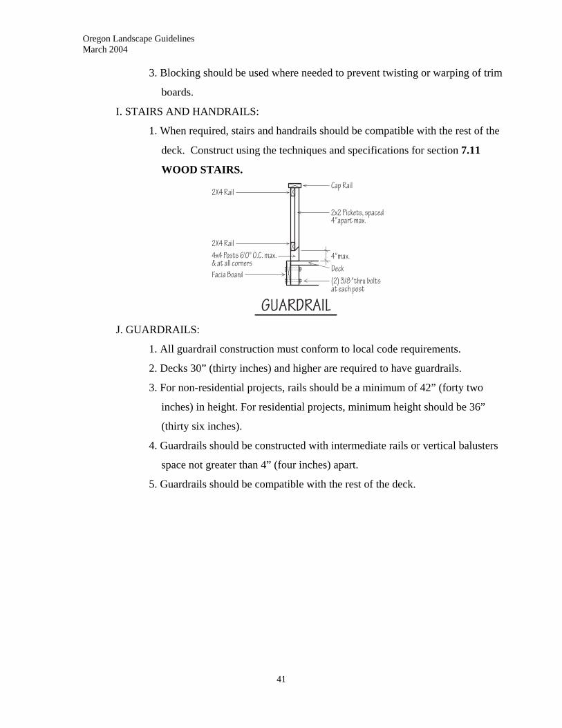
Oregon Landscape Guidelines March 2004
3. Blocking should be used where needed to prevent twisting or warping of trim
boards.
I. STAIRS AND HANDRAILS:
1. When required, stairs and handrails should be compatible with the rest of the
deck. Construct using the techniques and specifications for section 7.11
WOOD STAIRS.
J. GUARDRAILS:
1. All guardrail construction must conform to local code requirements.
2. Decks 30” (thirty inches) and higher are required to have guardrails.
3. For non-residential projects, rails should be a minimum of 42” (forty two
inches) in height. For residential projects, minimum height should be 36”
(thirty six inches).
4. Guardrails should be constructed with intermediate rails or vertical balusters
space not greater than 4” (four inches) apart.
5. Guardrails should be compatible with the rest of the deck.
41
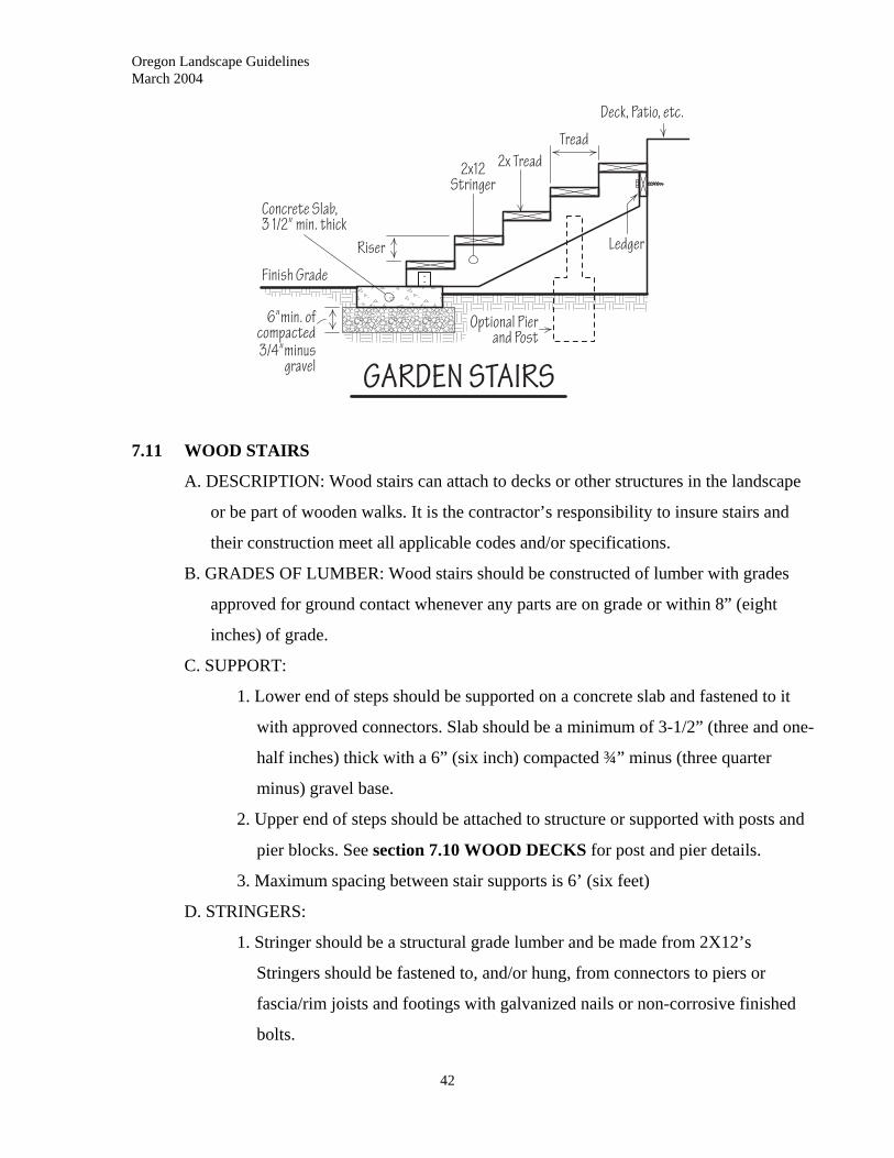
Oregon Landscape Guidelines March 2004
7.11 WOOD STAIRS
A. DESCRIPTION: Wood stairs can attach to decks or other structures in the landscape
or be part of wooden walks. It is the contractor’s responsibility to insure stairs and
their construction meet all applicable codes and/or specifications.
B. GRADES OF LUMBER: Wood stairs should be constructed of lumber with grades
approved for ground contact whenever any parts are on grade or within 8” (eight
inches) of grade.
C. SUPPORT:
1. Lower end of steps should be supported on a concrete slab and fastened to it
with approved connectors. Slab should be a minimum of 3-1/2” (three and one-
half inches) thick with a 6” (six inch) compacted ¾” minus (three quarter
minus) gravel base.
2. Upper end of steps should be attached to structure or supported with posts and
pier blocks. See section 7.10 WOOD DECKS for post and pier details.
3. Maximum spacing between stair supports is 6’ (six feet)
D. STRINGERS:
1. Stringer should be a structural grade lumber and be made from 2X12’s
Stringers should be fastened to, and/or hung, from connectors to piers or
fascia/rim joists and footings with galvanized nails or non-corrosive finished
bolts.
42
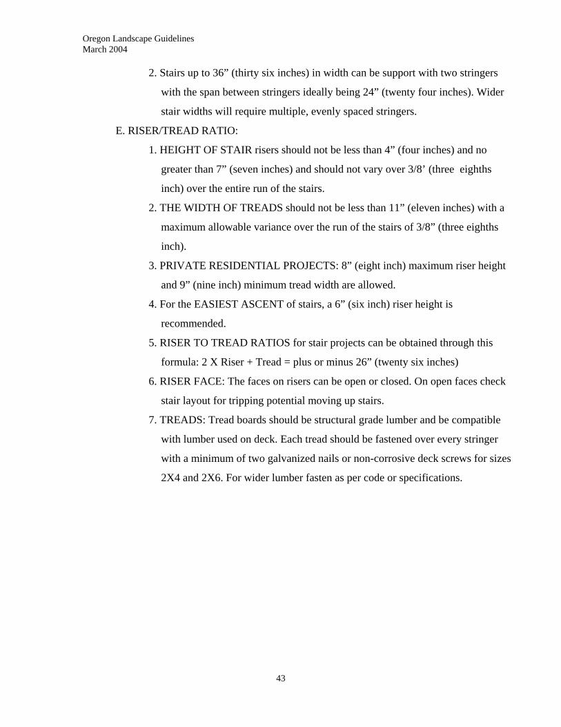
Oregon Landscape Guidelines March 2004
43
2. Stairs up to 36” (thirty six inches) in width can be support with two stringers
with the span between stringers ideally being 24” (twenty four inches). Wider
stair widths will require multiple, evenly spaced stringers.
E. RISER/TREAD RATIO:
1. HEIGHT OF STAIR risers should not be less than 4” (four inches) and no
greater than 7” (seven inches) and should not vary over 3/8’ (three eighths
inch) over the entire run of the stairs.
2. THE WIDTH OF TREADS should not be less than 11” (eleven inches) with a
maximum allowable variance over the run of the stairs of 3/8” (three eighths
inch).
3. PRIVATE RESIDENTIAL PROJECTS: 8” (eight inch) maximum riser height
and 9” (nine inch) minimum tread width are allowed.
4. For the EASIEST ASCENT of stairs, a 6” (six inch) riser height is
recommended.
5. RISER TO TREAD RATIOS for stair projects can be obtained through this
formula: 2 X Riser + Tread = plus or minus 26” (twenty six inches)
6. RISER FACE: The faces on risers can be open or closed. On open faces check
stair layout for tripping potential moving up stairs.
7. TREADS: Tread boards should be structural grade lumber and be compatible
with lumber used on deck. Each tread should be fastened over every stringer
with a minimum of two galvanized nails or non-corrosive deck screws for sizes
2X4 and 2X6. For wider lumber fasten as per code or specifications.
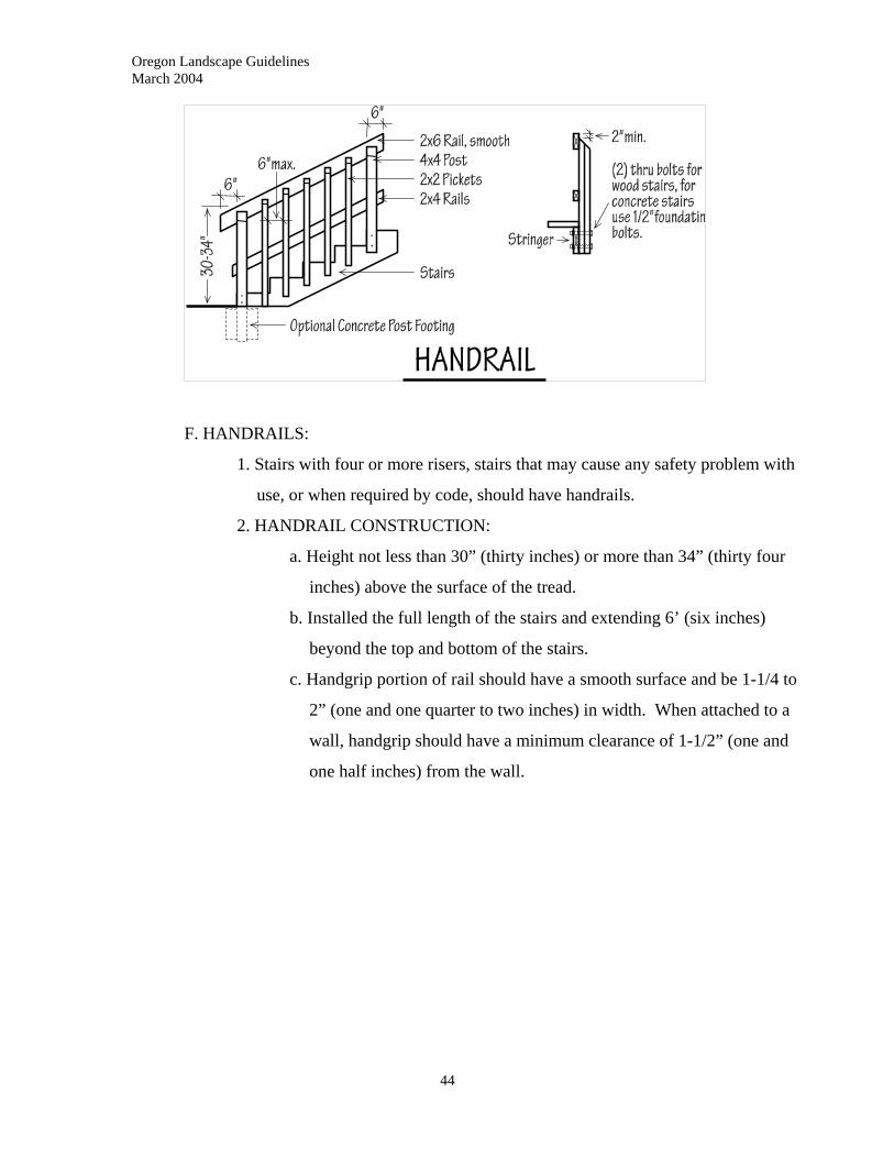
Oregon Landscape Guidelines March 2004
F. HANDRAILS:
1. Stairs with four or more risers, stairs that may cause any safety problem with
use, or when required by code, should have handrails.
2. HANDRAIL CONSTRUCTION:
a. Height not less than 30” (thirty inches) or more than 34” (thirty four
inches) above the surface of the tread.
b. Installed the full length of the stairs and extending 6’ (six inches)
beyond the top and bottom of the stairs.
c. Handgrip portion of rail should have a smooth surface and be 1-1/4 to
2” (one and one quarter to two inches) in width. When attached to a
wall, handgrip should have a minimum clearance of 1-1/2” (one and
one half inches) from the wall.
44
Oregon Landscape Guidelines March 2004
7.12 WOOD BENCHES
A. DESCRIPTION: Benches should be designed and built for the comfort and safety of
the end users.
B. LUMBER GRADES:
1. Posts and all parts of bench frames within 8” (eight inches) of grade should be
constructed of lumber grades suitable for ground contact.
2. Bench seats and backs should be an appearance grade of lumber approved for
structural use.
3. Trim boards should be appearance grade and be compatible with the rest of the
bench.
C. POST SUPPORTS:
1. POST SIZING: Posts should be sized to support the weight of the bench and a
live load as calculated for decks. Spacing of posts will be determined by the
size and type of lumber used and should prevent sagging and to create a
deflection of the bench surface under load.
2. WOOD DECK: When fastened to wood decks, the posts should extend through
the decking and be bolted to the deck’s sub-structure.
3. CONCRETE OR MASONRY PATIO: Best if posts can be anchored to surface
of patio. With a 4” (four inch) or thicker paving, concrete patio post connectors
can be anchored to the surface with expansion bolts. For masonry or stone
45
Oregon Landscape Guidelines March 2004
46
patios that do not have the concrete base, the post should extend through the
paving material and should be anchored in a 12” (twelve inch) wide by a
minimum 24” (twenty four inch) deep poured concrete pier.
4. FREE-STANDING: Free standing benches can have posts anchored to poured
concrete piers or can sit on the ground or paving surface.
a. Piers for anchored posts should be 12” (twelve inches) wide and a
minimum of 24” (twenty-four inches) deep.
b. Free standing benches should have a wide enough base and enough
weight to prevent tipping.
D. BENCH SEAT SUPPORTS:
1. Bench seat supports should fully support the bench seat and users.
2. If bench is designed to have the seat boards span the distance between posts
and seat supports, the distance between supports should not exceed 3’ (three
feet) maximum with 24” (twenty four inches) maximum recommended. The
sizing of greater spans and spans for composite materials will be determined by
the support design as in the sizing of deck joists and beams and should
conform to codes and/or manufacturers’ specifications.
3. Support lumber should be a grade approved for structural applications.
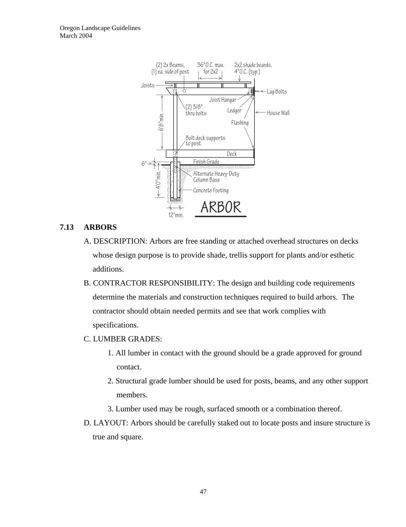
Oregon Landscape Guidelines March 2004
7.13 ARBORS
A. DESCRIPTION: Arbors are free standing or attached overhead structures on decks
whose design purpose is to provide shade, trellis support for plants and/or esthetic
additions.
B. CONTRACTOR RESPONSIBILITY: The design and building code requirements
determine the materials and construction techniques required to build arbors. The
contractor should obtain needed permits and see that work complies with
specifications.
C. LUMBER GRADES:
1. All lumber in contact with the ground should be a grade approved for ground
contact.
2. Structural grade lumber should be used for posts, beams, and any other support
members.
3. Lumber used may be rough, surfaced smooth or a combination thereof.
D. LAYOUT: Arbors should be carefully staked out to locate posts and insure structure is
true and square.
47
Oregon Landscape Guidelines March 2004
48
E. SUPPORT:
1. Free standing arbors should have shear support in two horizontal directions and
shear support vertically for beams and rafters.
2. Arbors attached to structures should be securely fastened to a ledger board as in
section 7.10 DECK CONSTRUCTION – F. LEDGER BOARDS.
F. POSTS:
1. LAYOUT: All posts should be set truly vertical and aligned if so specified.
2. SIZING AND SPACING:
a. Sizing and spacing of posts should comply with code and will vary
depending on the design and the size and spacing of beams.
b. Post size should be a minimum of 4X4 and spacing is determined by the
size of the beam and the load being carried.
3. SETTING POSTS:
a. Posts may be set in a concrete pier. Adjust size of pier to design or
specifications. Construct as per section 7.10 DECK
CONSTRUCTION – PIERS.
b. Posts may be installed on a concrete slab or footing pad with approved
metal post anchors that provide adequate shear support.
c. Posts may be attached to the structure of an existing deck or structure.
G. BEAMS:
1. Dimensions of arbor beams will depend on design, construction method,
spacing of supports, weight of structural members and variations in live load
for different regions.
2. SINGLE BEAM: Usually 4X6 to 4X12 set on top of beams and securely
fastened to them with approved post to beam connectors.
3. DOUBLE BEAM: Two beams, usually 2X6 to 2X12 can be sandwiched
around posts and bolted to them with a minimum of two appropriately sized
bolts.
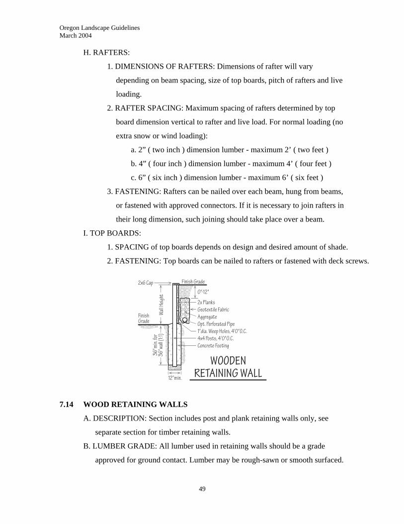
Oregon Landscape Guidelines March 2004
H. RAFTERS:
1. DIMENSIONS OF RAFTERS: Dimensions of rafter will vary
depending on beam spacing, size of top boards, pitch of rafters and live
loading.
2. RAFTER SPACING: Maximum spacing of rafters determined by top
board dimension vertical to rafter and live load. For normal loading (no
extra snow or wind loading):
a. 2” ( two inch ) dimension lumber - maximum 2’ ( two feet )
b. 4” ( four inch ) dimension lumber - maximum 4’ ( four feet )
c. 6” ( six inch ) dimension lumber - maximum 6’ ( six feet )
3. FASTENING: Rafters can be nailed over each beam, hung from beams,
or fastened with approved connectors. If it is necessary to join rafters in
their long dimension, such joining should take place over a beam.
I. TOP BOARDS:
1. SPACING of top boards depends on design and desired amount of shade.
2. FASTENING: Top boards can be nailed to rafters or fastened with deck screws.
7.14 WOOD RETAINING WALLS
A. DESCRIPTION: Section includes post and plank retaining walls only, see
separate section for timber retaining walls.
B. LUMBER GRADE: All lumber used in retaining walls should be a grade
approved for ground contact. Lumber may be rough-sawn or smooth surfaced.
49
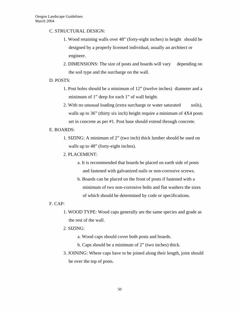
Oregon Landscape Guidelines March 2004
50
C. STRUCTURAL DESIGN:
1. Wood retaining walls over 48” (forty-eight inches) in height should be
designed by a properly licensed individual, usually an architect or
engineer.
2. DIMENSIONS: The size of posts and boards will vary depending on
the soil type and the surcharge on the wall.
D. POSTS:
1. Post holes should be a minimum of 12” (twelve inches) diameter and a
minimum of 1” deep for each 1” of wall height.
2. With no unusual loading (extra surcharge or water saturated soils),
walls up to 36” (thirty six inch) height require a minimum of 4X4 posts
set in concrete as per #1. Post base should extend through concrete.
E. BOARDS:
1. SIZING: A minimum of 2” (two inch) thick lumber should be used on
walls up to 48” (forty-eight inches).
2. PLACEMENT:
a. It is recommended that boards be placed on earth side of posts
and fastened with galvanized nails or non-corrosive screws.
b. Boards can be placed on the front of posts if fastened with a
minimum of two non-corrosive bolts and flat washers the sizes
of which should be determined by code or specifications.
F. CAP:
1. WOOD TYPE: Wood caps generally are the same species and grade as
the rest of the wall.
2. SIZING:
a. Wood caps should cover both posts and boards.
b. Caps should be a minimum of 2” (two inches) thick.
3. JOINING: Where caps have to be joined along their length, joint should
be over the top of posts.
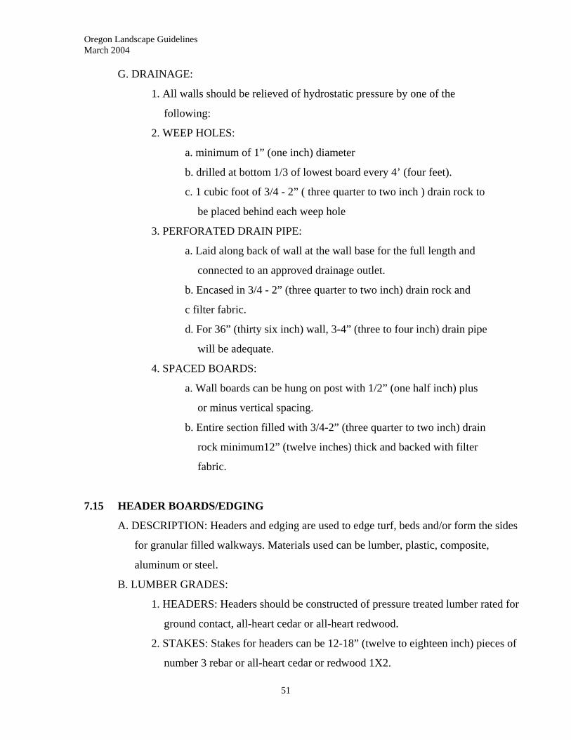
Oregon Landscape Guidelines March 2004
51
G. DRAINAGE:
1. All walls should be relieved of hydrostatic pressure by one of the
following:
2. WEEP HOLES:
a. minimum of 1” (one inch) diameter
b. drilled at bottom 1/3 of lowest board every 4’ (four feet).
c. 1 cubic foot of 3/4 - 2” ( three quarter to two inch ) drain rock to
be placed behind each weep hole
3. PERFORATED DRAIN PIPE:
a. Laid along back of wall at the wall base for the full length and
connected to an approved drainage outlet.
b. Encased in 3/4 - 2” (three quarter to two inch) drain rock and
c filter fabric.
d. For 36” (thirty six inch) wall, 3-4” (three to four inch) drain pipe
will be adequate.
4. SPACED BOARDS:
a. Wall boards can be hung on post with 1/2” (one half inch) plus
or minus vertical spacing.
b. Entire section filled with 3/4-2” (three quarter to two inch) drain
rock minimum12” (twelve inches) thick and backed with filter
fabric.
7.15 HEADER BOARDS/EDGING
A. DESCRIPTION: Headers and edging are used to edge turf, beds and/or form the sides
for granular filled walkways. Materials used can be lumber, plastic, composite,
aluminum or steel.
B. LUMBER GRADES:
1. HEADERS: Headers should be constructed of pressure treated lumber rated for
ground contact, all-heart cedar or all-heart redwood.
2. STAKES: Stakes for headers can be 12-18” (twelve to eighteen inch) pieces of
number 3 rebar or all-heart cedar or redwood 1X2.

Oregon Landscape Guidelines March 2004
C. LAYOUT: All headers should be laid true to line and flush to grade where edging
lawns.
D. STRAIGHT HEADERS:
1. Headers will be butt jointed when needed for length.
2. Stakes should be placed 4’ (four feet) on center with two stakes at each joint.
Stakes should be driven flush to the top of the header and fastened with two
galvanized nails or non-corrosive screw.
3. Alternate method, use number 3 rebar, drill vertical holes to match rebar size
every four feet with a hole 4-6” (four to six inches) from each end, and drive
rebar flush with header surface.
52
Oregon Landscape Guidelines March 2004
E. HEADERS WITH SLIGHT CURVE:
1. Headers with slight curves should be laminated from two 1X4 lumber approved
for ground contact. Joints of lumber should be staggered along the length with
a minimum 48” (forty eight inch) spacing.
2. Laminations should be fastened every 12” (twelve inches) with galvanized
nails or non-corrosive finished screws.
3. Using the same wood stakes, as in straight headers, space stakes 3’ (three feet)
on center maximum along the outside of curve, with two stakes placed on
either side of each butt joint and one stake on either side of header when there
is a directional change. Fasten securely to header with non-corrosive finished
nails or screws.
F. HEADERS WITH A STRONG CURVE:
1. Headers with strong curves should be laminated from four or more 3/8X4
(three eighths by four) boards approved for ground contact. Joints should be
staggered with a minimum of 48” (forty eight inches) spacing.
53

Oregon Landscape Guidelines March 2004
54
2. Fasten laminations every 12” (twelve inches) with galvanized nails or non-
corrosive finished screws.
3. Space stakes every three feet along outside of curve, at each joint and one on
either side of header at points of directional change. Fasten securely to header
with non-corrosive finished nails or screws.
G. PLASTIC AND STEEL: Plastic and steel edging should be installed as per
manufacturer’s specifications.
Oregon Landscape Guidelines March 2004
55
8.0 HARDSCAPES – CONCRETE CONSTRUCTION
____________________________________________________________
8.01 GENERAL DESCRIPTION:
Concrete construction provides durable hardscape features that are used for both
functional and esthetic purposes in the landscape.
8.02 WORK INCLUDED:
This section includes the construction of concrete footings, walls, patios, walks and
stairs, and mowing strips.
8.03 QUALITY ASSURANCE:
Permits may be required for concrete construction and concrete construction may have to
be phased in with the work of a general contractor. The landscape contractor will be
responsible for ensuring that all permits needed are obtained and that all work conforms
to project code and/or specifications.
8.04 SUBMITTALS:
On some jobs, samples of concrete mix, finish, color or aggregate for seeded exposed
aggregate concrete may be required.
8.05 EXISTING CONDITIONS:
Methods of construction and structural details of concrete work will vary depending on
soil types, design specifications, and whether the work is built on cut or fill.
8.06 SCHEDULING:
Prior to the commencement of concrete work, all related grading should be completed, all
piping and wiring laid and sleeves placed. Generally, concrete work should be
completed before irrigation and plants are installed.
Oregon Landscape Guidelines March 2004
56
8.07 CONTRACTOR RESPONSIBILITY:
The contractor will be responsible for insuring proper drainage, both on and off, all
concrete flatwork.
8.08 MATERIALS - CONCRETE CONSTRUCTION:
A. BASE MATERIALS:
1. SAND: Clean washed builders sand, uniform in size and texture and free of
clay lumps or stones.
2. GRAVEL: 3/8” (three eighths inch) pea gravel or washed crushed gravel.
3. AGGREGATE SUB-BASE: Should conform to the standards set by the
Portland Cement Association. Usually 3/4” minus.
B. REINFORCEMENT:
1. STEEL REBAR: Deformed, new billet steel bars. Size of rebar will depend on
the spacing of reinforcement, the depth of the concrete, and structural
requirements as set forth in code, design and/or specifications.
2. TIE WIRE: Standard AWG #14 (American Wire Gauge) wire.
3. WELDED WIRE MESH: AWG #10 (American Wire Gauge) wire welded to
form a 6”X6” (six inch by six inch) mesh.
C. CONCRETE MIX:
1. CEMENT: Standard Portland Cement, domestic gray, Type II.
2. AGGREGATES:
a. All aggregates use should be free of all animal or vegetable matter.
b. FINE: Clean washed builders sand or aggregates manufactured from
crushed rock, with sharp particles graded from a #100 sieve to 1/4”
(one quarter inch).
c. COARSE: Gravel graded from 1/4 to 3/4” (one quarter to three quarter
inch).
3. ADMIXTURES: If used, admixtures should be of the intended type (hardening,
coloring, etc.) and used following the manufacturer’s specifications.
D. EXPANSION JOINTS: Wood, metal or composite strips, sized with a minimum 1/4”
(one quarter inch) width and with a depth equal to the concrete pour.
Oregon Landscape Guidelines March 2004
57
E. AGGREGATES FOR SEEDED EXPOSED CONCRETE: Smooth, washed gravel
from 1/4” to 1-1/2” (one quarter to one and one half inch). Can be chosen for texture
and color.
F. WATERPROOFING PRODUCTS: Waterproofing products can be painted on, or
attached to wall surfaces and imbedded in concrete. When used, they should be
applied to manufacturer’s specifications.
8.09 GENERAL REQUIREMENTS CONCRETE WORK
A. FORMING:
1. Wood or metal frames should be used for all concrete pours with the exception
of footings or post pours into compacted or undisturbed soil.
2. Forms should be placed with smooth side toward the pour and adequately
staked and braced for the maximum load in order to maintain their position
during pouring and finishing operations.
3. Prior to pouring, forming should be treated on the concrete side to prevent
concrete from adhering to the form.
4. Forming should be put in place with screws or duplex nails to allow easy
stripping and removal.
5. Forming material used to be left in project as headers and/or expansion joints
should be taped prior to pouring and finishing to maintain its surface.
B. BURIED INSERTS:
1. All reinforcement, knock-outs, conduits, piping or other inserts that are to
remain buried within the concrete should be accurately placed and securely
fastened into place prior to pour.
2. It is the responsibility of the contractor to ascertain the requirements for any
inserts, accurately place and anchor them according to code and/or
specifications.
C. REINFORCEMENT:
1. All lapped joints of rebar should be a minimum of 30 times the diameter of the
rod and should be tied at all joints/intersections with ties not further apart than
24” (twenty four inches).
Oregon Landscape Guidelines March 2004
58
2. All rebar and wire mesh reinforcement should be a minimum 2” (two inches) in
from the edges of any pour.
3. Reinforcements should be placed at the manner and depth in the concrete
specified by code or design.
4. Reinforcement should not extend through expansion or control joints. If a tie is
required across these, use a dowel or keyed joint.
D. EXPANSION AND CONTROL JOINTS
1. Used to minimize or control cracking of the concrete.
2. Should be space a minimum of every 10’ (ten feet) in both horizontal directions
and at all corners.
3. Install where concrete work abuts a structure or slab.
4. Control joints can be made at time of pour with a jointing tool or cut into cured
concrete.
5. Control joints should form a weakened plane 1/5 (one fifth) the thickness of the
slab.
E. MOISTURE LEVEL OF SUB-BASE AND BASE:
1. When sub-base is an expansive type soil, do not pour concrete until sub-base
has been thoroughly and completely moistened and has expanded.
2. Prior to pouring any base should be evenly moistened to prevent wicking of
water out of the concrete mix and preventing proper curing.
F. CONCRETE PLACEMENT:
1. All concrete should be placed in a continuous pour between stopping points,
worked into forms to eliminate air pockets and leveled to top or forms.
2. Flat surfaces should be leveled with a “bull float” or similar piece of
equipment.
3. All exposed edges should be finished with a s slight round or bull nose.
4. Finish troweling should be done when surface of work has lost its water sheen
and before hardening of concrete.
G. WALL FINISHES: Many types of wall finishing are available. Most will require
removal of wall forms prior to work. Apply as per manufacturer’s specifications.
Oregon Landscape Guidelines March 2004
59
H. FLAT FINISHES:
1. Any of the following finishes are suitable for flatwork:
a. troweled
b. broom finish
c. sand finish
d. washed finish
e. rock salt finish
f. seeded exposed finish
g. stamped finish
2. Choice and timing of finish will depend on intended use, design specifications,
and finish type.
I. CURING:
1. Concrete must be kept damp a minimum of 72 (seventy two) hours before
forms are removed to allow complete curing.
2. Moisture can be retained using sprinklers, waterproof paper without coatings,
burlap, straw, sand or other approved materials.
J. FORM REMOVAL: Care needs to be taken when removing forms to prevent breakage
at corners, openings edges of work.
8.10 CONCRETE FOOTINGS
A. DIMENSIONS
1. Depth and width concrete footings will be determined by soil type, height of
the wall, and construction methods. Size should be sufficient to meet all code
requirements.
2. Depth of footings should be sufficient to extend below frost line.
B. SUB-GRADE:
1. Should be free of organic matter, large clay lumps/clods or stones larger than
one inch.
2. Sub-grade should be compacted to 95% relative density.
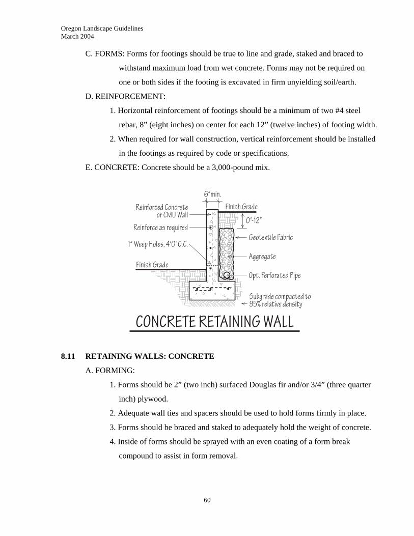
Oregon Landscape Guidelines March 2004
C. FORMS: Forms for footings should be true to line and grade, staked and braced to
withstand maximum load from wet concrete. Forms may not be required on
one or both sides if the footing is excavated in firm unyielding soil/earth.
D. REINFORCEMENT:
1. Horizontal reinforcement of footings should be a minimum of two #4 steel
rebar, 8” (eight inches) on center for each 12” (twelve inches) of footing width.
2. When required for wall construction, vertical reinforcement should be installed
in the footings as required by code or specifications.
E. CONCRETE: Concrete should be a 3,000-pound mix.
8.11 RETAINING WALLS: CONCRETE
A. FORMING:
1. Forms should be 2” (two inch) surfaced Douglas fir and/or 3/4” (three quarter
inch) plywood.
2. Adequate wall ties and spacers should be used to hold forms firmly in place.
3. Forms should be braced and staked to adequately hold the weight of concrete.
4. Inside of forms should be sprayed with an even coating of a form break
compound to assist in form removal.
60
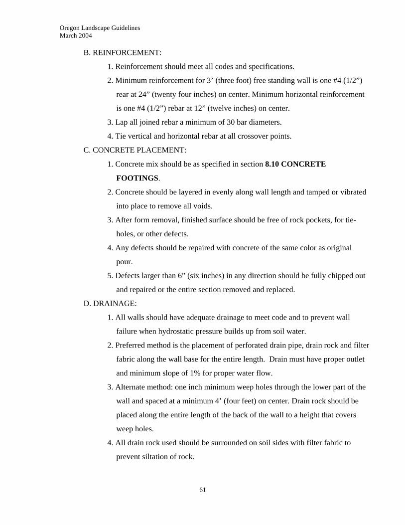
Oregon Landscape Guidelines March 2004
61
B. REINFORCEMENT:
1. Reinforcement should meet all codes and specifications.
2. Minimum reinforcement for 3’ (three foot) free standing wall is one #4 (1/2”)
rear at 24” (twenty four inches) on center. Minimum horizontal reinforcement
is one #4 (1/2”) rebar at 12” (twelve inches) on center.
3. Lap all joined rebar a minimum of 30 bar diameters.
4. Tie vertical and horizontal rebar at all crossover points.
C. CONCRETE PLACEMENT:
1. Concrete mix should be as specified in section 8.10 CONCRETE
FOOTINGS.
2. Concrete should be layered in evenly along wall length and tamped or vibrated
into place to remove all voids.
3. After form removal, finished surface should be free of rock pockets, for tie-
holes, or other defects.
4. Any defects should be repaired with concrete of the same color as original
pour.
5. Defects larger than 6” (six inches) in any direction should be fully chipped out
and repaired or the entire section removed and replaced.
D. DRAINAGE:
1. All walls should have adequate drainage to meet code and to prevent wall
failure when hydrostatic pressure builds up from soil water.
2. Preferred method is the placement of perforated drain pipe, drain rock and filter
fabric along the wall base for the entire length. Drain must have proper outlet
and minimum slope of 1% for proper water flow.
3. Alternate method: one inch minimum weep holes through the lower part of the
wall and spaced at a minimum 4’ (four feet) on center. Drain rock should be
placed along the entire length of the back of the wall to a height that covers
weep holes.
4. All drain rock used should be surrounded on soil sides with filter fabric to
prevent siltation of rock.
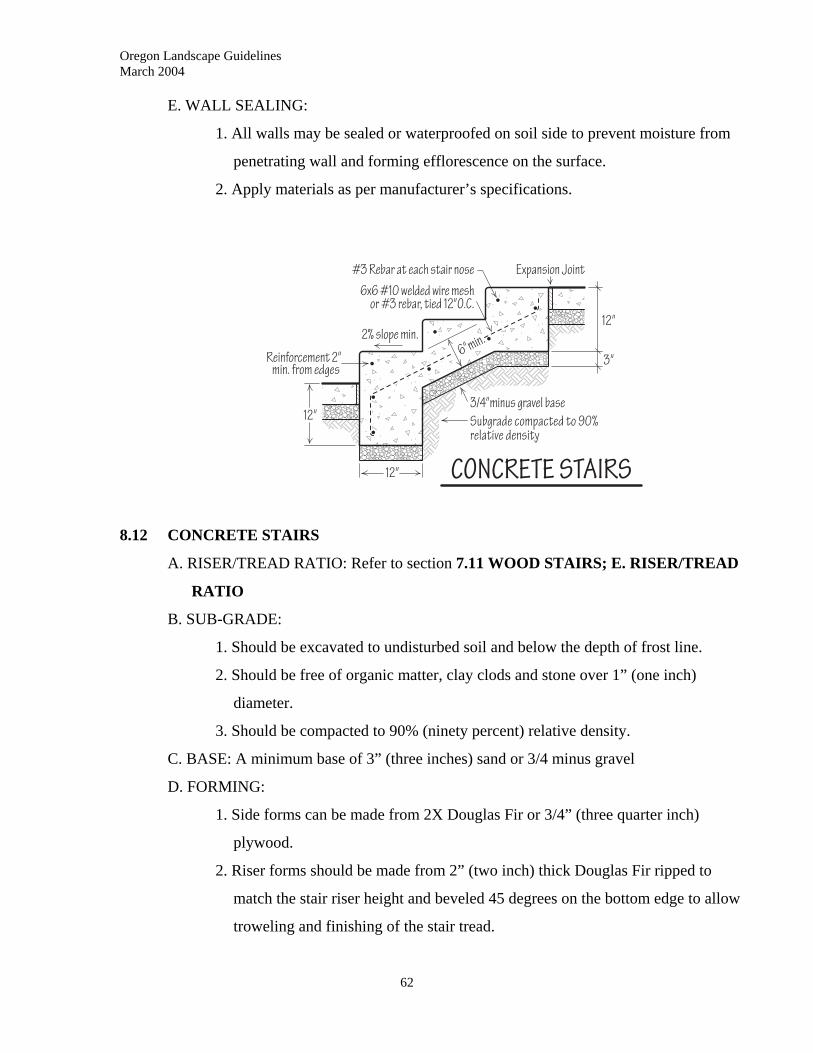
Oregon Landscape Guidelines March 2004
E. WALL SEALING:
1. All walls may be sealed or waterproofed on soil side to prevent moisture from
penetrating wall and forming efflorescence on the surface.
2. Apply materials as per manufacturer’s specifications.
8.12 CONCRETE STAIRS
A. RISER/TREAD RATIO: Refer to section 7.11 WOOD STAIRS; E. RISER/TREAD
RATIO
B. SUB-GRADE:
1. Should be excavated to undisturbed soil and below the depth of frost line.
2. Should be free of organic matter, clay clods and stone over 1” (one inch)
diameter.
3. Should be compacted to 90% (ninety percent) relative density.
C. BASE: A minimum base of 3” (three inches) sand or 3/4 minus gravel
D. FORMING:
1. Side forms can be made from 2X Douglas Fir or 3/4” (three quarter inch)
plywood.
2. Riser forms should be made from 2” (two inch) thick Douglas Fir ripped to
match the stair riser height and beveled 45 degrees on the bottom edge to allow
troweling and finishing of the stair tread.
62
Oregon Landscape Guidelines March 2004
63
3. All forms should be adequately staked and braced to allow for maximum
concrete load without give or failure.
4. All riser forms over 3’ (three feet) in length should be reinforced with 1X4
strongbacks placed 3’ (three feet) on center maximum and nailed over top of
risers.
5. Riser forms should be placed to allow a 2% (two percent) or 1/4” (one quarter
inch) per 1’ (one foot) fall from back of tread to front for drainage.
6. Inside of forms should be sprayed with an even coating of a form break
compound to assist in form removal.
E. REINFORCEMENT:
1. Stairs should be reinforced with either 6x6#10 welded wire mesh bent to fit the
contour of the stairs or with #3 (3/8” - three eighths inch) rebar 12” (twelve
inches) on center in both directions.
2. All reinforcement should be a minimum of 2” (two inches) from edge of
concrete.
F. EXPANSION JOINTS: Approved expansion joints should be installed in stairs
exceeding 10’ (ten feet) in width and at the top or bottom of stairs abutting walks,
patios or structures.
G. CONCRETE:
1. Concrete should be a minimum of a 3,000 lb. mix.
2. Concrete should be poured a minimum of 6 inches thick as diagrammed and
finished as designed or specified.
H. HANDRAILS:
1. Handrails should comply with all codes and specifications.
2. May be bolted to finished concrete or included as part of pour.
3. Sizes and minimum specifications refer to section 7.11 WOOD STAIRS
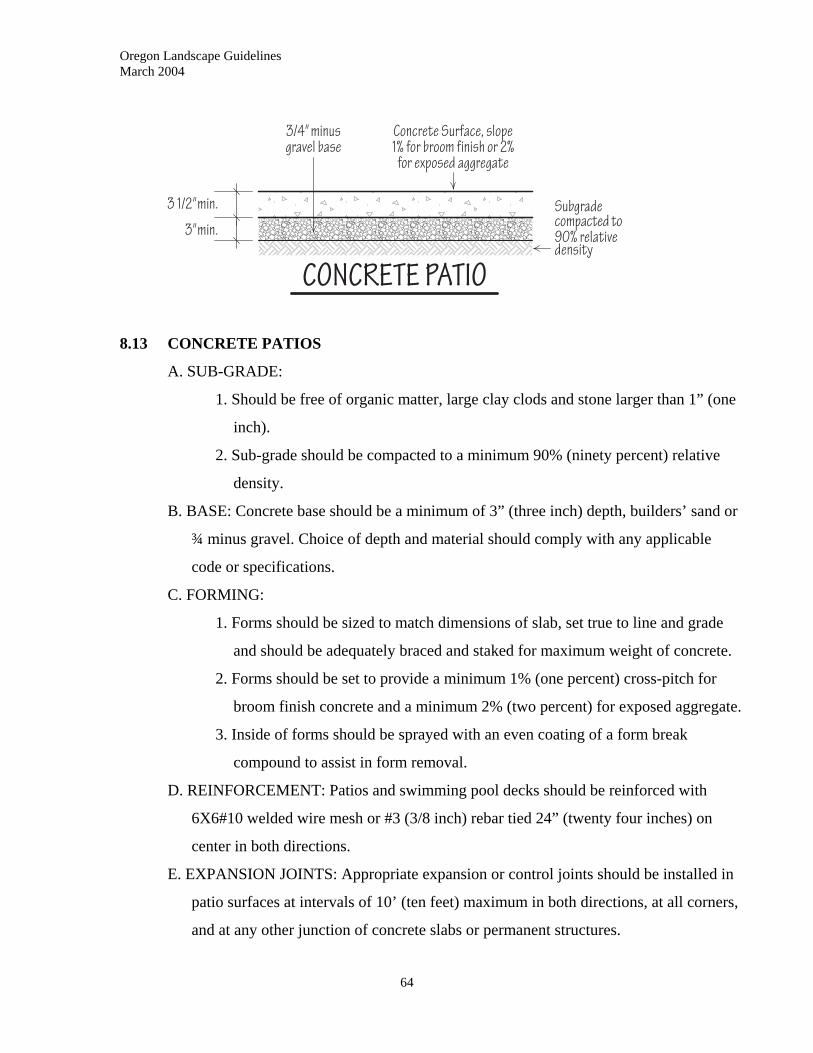
Oregon Landscape Guidelines March 2004
8.13 CONCRETE PATIOS
A. SUB-GRADE:
1. Should be free of organic matter, large clay clods and stone larger than 1” (one
inch).
2. Sub-grade should be compacted to a minimum 90% (ninety percent) relative
density.
B. BASE: Concrete base should be a minimum of 3” (three inch) depth, builders’ sand or
¾ minus gravel. Choice of depth and material should comply with any applicable
code or specifications.
C. FORMING:
1. Forms should be sized to match dimensions of slab, set true to line and grade
and should be adequately braced and staked for maximum weight of concrete.
2. Forms should be set to provide a minimum 1% (one percent) cross-pitch for
broom finish concrete and a minimum 2% (two percent) for exposed aggregate.
3. Inside of forms should be sprayed with an even coating of a form break
compound to assist in form removal.
D. REINFORCEMENT: Patios and swimming pool decks should be reinforced with
6X6#10 welded wire mesh or #3 (3/8 inch) rebar tied 24” (twenty four inches) on
center in both directions.
E. EXPANSION JOINTS: Appropriate expansion or control joints should be installed in
patio surfaces at intervals of 10’ (ten feet) maximum in both directions, at all corners,
and at any other junction of concrete slabs or permanent structures.
64
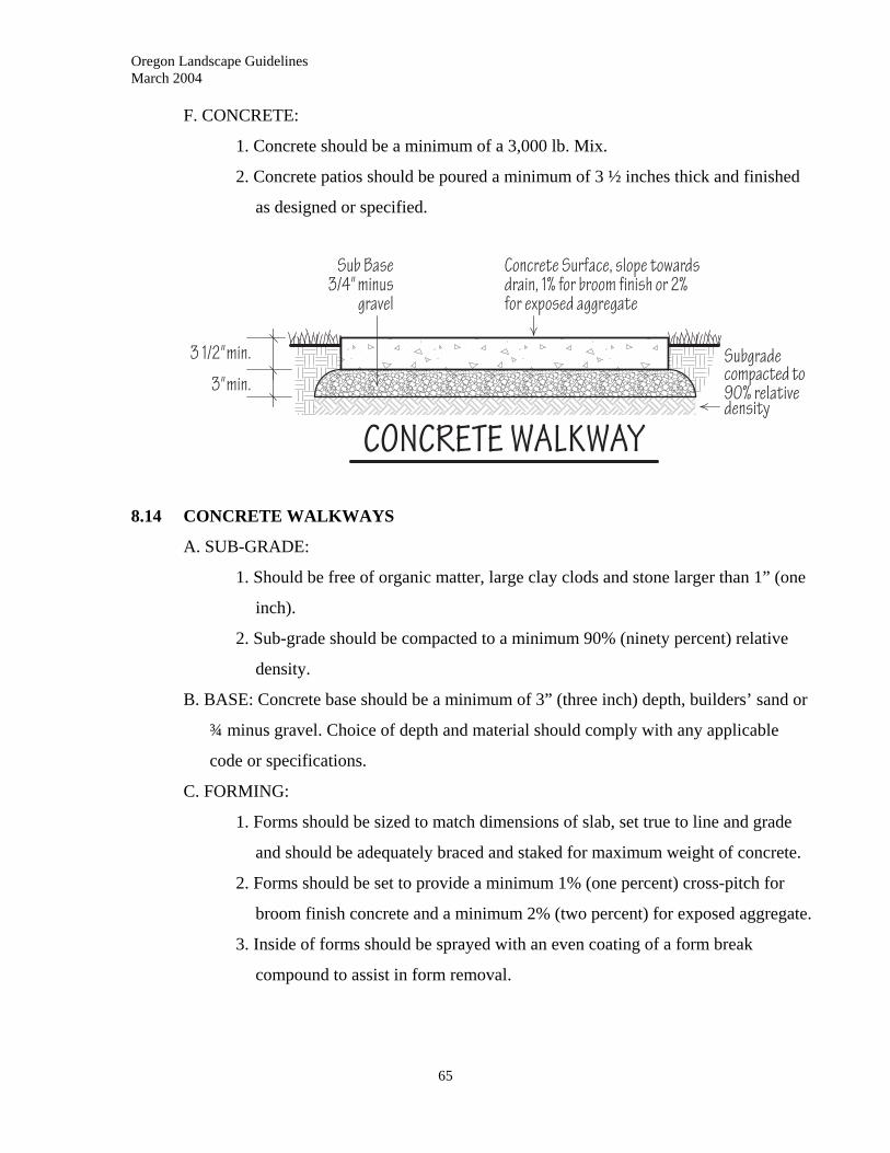
Oregon Landscape Guidelines March 2004
F. CONCRETE:
1. Concrete should be a minimum of a 3,000 lb. Mix.
2. Concrete patios should be poured a minimum of 3 ½ inches thick and finished
as designed or specified.
8.14 CONCRETE WALKWAYS
A. SUB-GRADE:
1. Should be free of organic matter, large clay clods and stone larger than 1” (one
inch).
2. Sub-grade should be compacted to a minimum 90% (ninety percent) relative
density.
B. BASE: Concrete base should be a minimum of 3” (three inch) depth, builders’ sand or
¾ minus gravel. Choice of depth and material should comply with any applicable
code or specifications.
C. FORMING:
1. Forms should be sized to match dimensions of slab, set true to line and grade
and should be adequately braced and staked for maximum weight of concrete.
2. Forms should be set to provide a minimum 1% (one percent) cross-pitch for
broom finish concrete and a minimum 2% (two percent) for exposed aggregate.
3. Inside of forms should be sprayed with an even coating of a form break
compound to assist in form removal.
65

Oregon Landscape Guidelines March 2004
66
D. REINFORCEMENT: Patios and swimming pool decks should be reinforced with #10
welded wire mesh or #3 (3/8 inch) rebar tied 24” (twenty four inches) on enter in both
directions.
E. EXPANSION JOINTS: Appropriate expansion or control joints should be installed in
walkway at maximum intervals of two times the width of the walk.
F. CONCRETE:
1. Concrete should be a minimum of a 3,000 lb. mix
2. Concrete walks should be poured a minimum of 3 ½ inches thick and finished
as designed or specified.
Oregon Landscape Guidelines March 2004
67
9.0 HARDSCAPES: STONE AND MASONRY
____________________________________________________________
9.01 DESCRIPTION
The construction of functional and esthetic landscape elements through the use of brick,
pavers modular concrete units, natural stone, concrete block and tile.
9.02 WORK INCLUDED
Includes the construction of masonry, segmental and stone walls and paving.
9.03 QUALITY ASSURANCE
A. PERMITS AND CODES; Contractor responsible for ensuring all permits have been
obtained and assuring walls meet any applicable codes.
B. WALL LIMITATIONS: For walls with higher surcharge possibilities and retaining
walls over 4’ (four feet) in height, structural design and specifications should be
carried out by a properly licensed individual.
9.04 SCHEDULING
A. SLEEVES: Sleeves for utilities and irrigation should be installed prior to the
construction of stone or masonry construction.
B. SCHEDULE: All masonry, stone and segmental construction should be completed
prior to the final installation of irrigation and plantings.
9.05 BASE MATERIALS
Refer to section 8.08 MATERIALS - CONCRETE CONSTRUCTION - A. BASE
MATERIALS.
9.06 REINFORCEMENT
Refer to section 8.10 MATERIALS - CONCRETE CONSTRUCTION –B.
REINFORCEMENT.
Oregon Landscape Guidelines March 2004
68
9.07 CONCRETE MIX
Refer to section 8.10 MATERIALS - CONCRETE CONSTRUCTION –C.
CONCRETE MIX.
9.08 MORTAR
A mortar mix approved for the construction application should be used. Mortar shall
comply with ATM C270 Type S (as per UBC 21-15).
9.09 GROUT
Grout used for reinforced walls shall comply with ASTM C476 (as per UBC 21-19).
9.10 MASONRY UNITS
A. BRICK: Building and paving bricks are manufactured in many sizes, colors and
densities, and may be a recycled product. Grades and sizes are listed in ASTM C216,
Grade SW, Type FBS.
B. CONCRETE BUILDING BLOCK: Concrete building blocks are manufactured in a
variety of sizes and shapes from cement, sand and lightweight or normal weight
aggregate. Grades and sizes should conform to ASTM C90-01.
C. CONCRETE PAVERS:
1. Manufactured in a variety of shapes, sizes, colors and some designed to
interlock.
2. Available in different thicknesses for vehicular and pedestrian traffic.
3. Pavers shall be manufactured to ASTM C936 specifications.
9.11 STONE
A. QUARRIED STONE:
1. GRANITE: hard, dense igneous rock used for paving, curbing, and veneer.
Granite occurs in many colors; is available rough cut and as cut-stone paving
units; and can be polished.
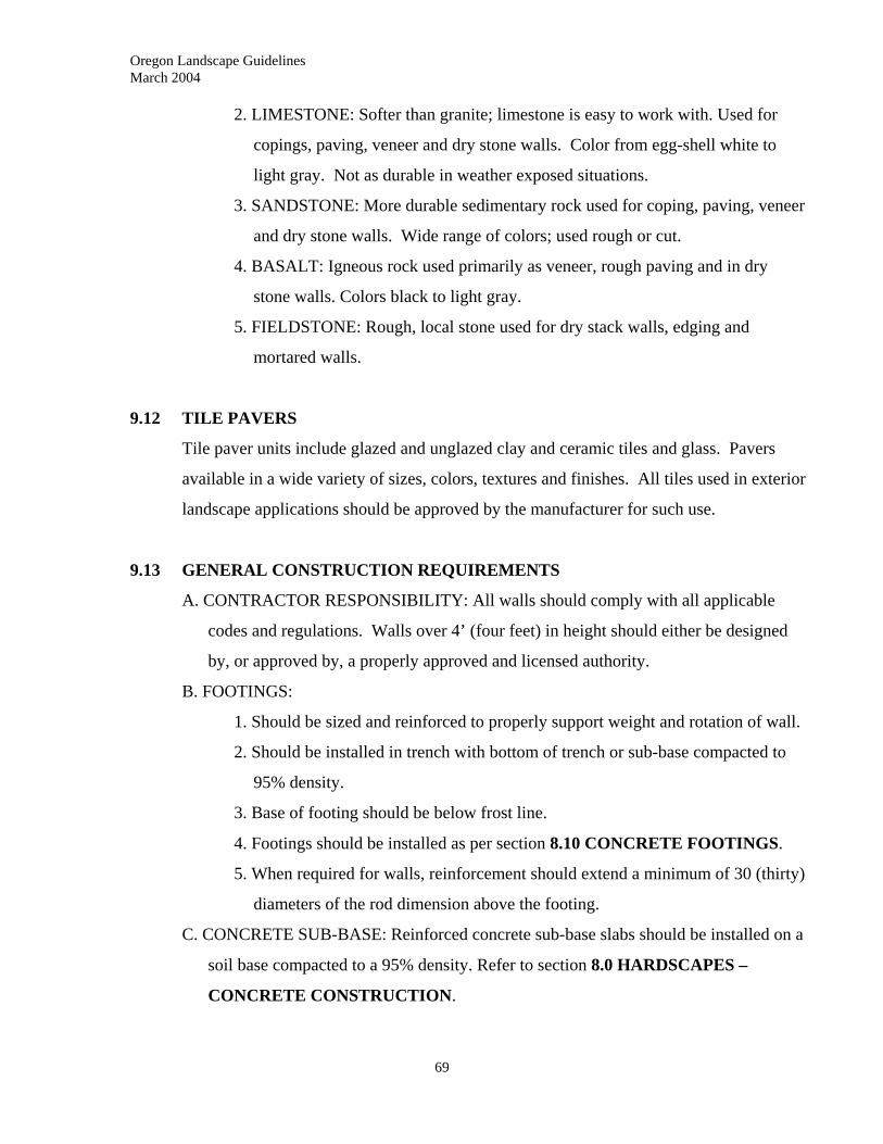
Oregon Landscape Guidelines March 2004
69
2. LIMESTONE: Softer than granite; limestone is easy to work with. Used for
copings, paving, veneer and dry stone walls. Color from egg-shell white to
light gray. Not as durable in weather exposed situations.
3. SANDSTONE: More durable sedimentary rock used for coping, paving, veneer
and dry stone walls. Wide range of colors; used rough or cut.
4. BASALT: Igneous rock used primarily as veneer, rough paving and in dry
stone walls. Colors black to light gray.
5. FIELDSTONE: Rough, local stone used for dry stack walls, edging and
mortared walls.
9.12 TILE PAVERS
Tile paver units include glazed and unglazed clay and ceramic tiles and glass. Pavers
available in a wide variety of sizes, colors, textures and finishes. All tiles used in exterior
landscape applications should be approved by the manufacturer for such use.
9.13 GENERAL CONSTRUCTION REQUIREMENTS
A. CONTRACTOR RESPONSIBILITY: All walls should comply with all applicable
codes and regulations. Walls over 4’ (four feet) in height should either be designed
by, or approved by, a properly approved and licensed authority.
B. FOOTINGS:
1. Should be sized and reinforced to properly support weight and rotation of wall.
2. Should be installed in trench with bottom of trench or sub-base compacted to
95% density.
3. Base of footing should be below frost line.
4. Footings should be installed as per section 8.10 CONCRETE FOOTINGS.
5. When required for walls, reinforcement should extend a minimum of 30 (thirty)
diameters of the rod dimension above the footing.
C. CONCRETE SUB-BASE: Reinforced concrete sub-base slabs should be installed on a
soil base compacted to a 95% density. Refer to section 8.0 HARDSCAPES –
CONCRETE CONSTRUCTION.
Oregon Landscape Guidelines March 2004
70
D. REINFORCEMENT:
1. Vertical and horizontal rods should be tied at a minimum of 18” (eighteen
inches) in each direction.
2. Horizontal reinforcement in low brick walls may be welded wire mesh
imbedded in the mortared joints.
3. All laps of reinforcement rods should be a minimum of 30 (thirty) rod
diameters.
E. BRICK CONSTRUCTION:
1. Prior to construction, all brick should be clean and free of dirt.
2. Brick should be thoroughly wetted but not soaked.
3. Bed and end joints should be full and exposed. Joints on brick faces should be
struck flush or tooled as specified.
F. MORTAR:
1. Should be well mixed to a uniform consistency and not used if standing for
more than two hours.
2. Re-tempering may be accomplished by adding water as needed. All mortar
must be used within 2-1/2 hours of mixing.
G. MORTARED JOINTS:
1. Flush joints are not recommended
2. Tooled joints should be made with a metal jointing tool.
3. Raked joints should be formed and recessed approximately 3/8” (three eighths
inch) with a jointing tool, but they are not recommended for exterior
applications.
H. GROUT: Should be placed in all voids of reinforced brick or concrete block masonry
unit walls and should be puddled or vibrated to remove air pockets and to properly
place using a blunt-end rod or vibrating tool.
I. CLEANUP:
1. Mortar and/or grout spilled on exposed surfaces should be removed with clean
water before stain has been allowed to set.
2. Stained masonry may be cleaned with a proprietary cleaning product as
recommended by the manufacturer and thoroughly rinsed with clean water.
Oregon Landscape Guidelines March 2004
Use all specified personal protective equipment and environmental protection
measures.
9.14 BRICK WALLS
A. TYPES OF CONSTRUCTION:
1. Walls of all sizes may be brick veneer.
2. Walls shall conform to all current UBC code requirements
B. FOOTINGS: Refer to sections 3.01 - A. FOOTINGS and 8.10 CONCRETE
FOOTINGS
C. REINFORCEMENT: In hollow or two-wythe construction, see structural notes for
placement and size of reinforcement (9.13.D.).
D. BRICK INSTALLATION: All brick should be laid plumb, level and true to line in the
specified pattern unless otherwise specified.
E. GROUTING: The cavity space in double wall constructed walls should be filled with
mortar or grout.
F. WALL CAP: Brick walls should be capped either with brick, stone, or tile as specified.
Cap bricks are usually laid perpendicular to the wall face.
G. DRAINAGE: Refer to 8.11 CONCRETE WALLS - Section D.; DRAINAGE
H. WALL SEALING: Refer to 8.11 CONCRETE WALLS - Section E.; WALL
SEALING.
71
Oregon Landscape Guidelines March 2004
72
9.15 CONCRETE BLOCK WALLS
A. WALL CONSTRUCTION: Concrete block walls usually have a nominal thickness of
8” (eight inches) and are built of standard 8x8x16 inch concrete block.
B. FOOTINGS: Refer to sections 3.01 FOOTINGS and 8.10 CONCRETE
FOOTINGS.
C. REINFORCEMENT:
1. Walls 24-48” (twenty four to forty-eight inch) height should have #4
reinforcing bar installed every 24” (twenty four inches) on center vertically and
every 16” (sixteen inches) on center horizontally embedded in the mortar
joints.
2. Freestanding walls, less than 24” (twenty four inches) in height only require
reinforcement for the top course.
D. BLOCK INSTALLATION: All block units should be laid level and true to line in a
running bond pattern and with 3/8” (three eighths inch) mortar joints.
E. GROUTING: All cells in block should be filled with grout or mortar.
F. WALL CAP: All concrete block walls should be capped with a minimum of a 2” (two
inch) cap unless otherwise specified.
G. DRAINAGE: Refer to 8.11 CONCRETE WALLS - Section D.; DRAINAGE
H. WALL SEALING: Refer to 8.11 CONCRETE WALLS - Section E.; WALL
SEALING.
I. WALL FINISH: Concrete block walls can be left plain, plastered or stuccoed, faced or
painted as desired and/or specified.
9.16 STONE WALLS
A. TYPES OF CONSTRUCTION: Stone walls can be constructed of almost any stone;
may be built from cut and dressed and/or rough stone; and may be built as mortared
or dry stone construction. Free standing walls over 24” (twenty four inches) in height
should be double-wall construction with stone rubble between wythes.
B. FOOTINGS:
1. Mortared stone walls should be constructed with a concrete footing as per
section 3.01 - A FOOTINGS.
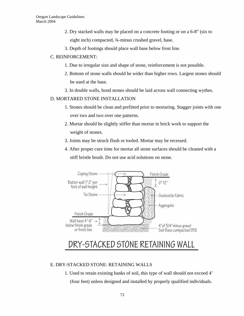
Oregon Landscape Guidelines March 2004
2. Dry stacked walls may be placed on a concrete footing or on a 6-8” (six to
eight inch) compacted, ¾-minus crushed gravel, base.
3. Depth of footings should place wall base below frost line.
C. REINFORCEMENT:
1. Due to irregular size and shape of stone, reinforcement is not possible.
2. Bottom of stone walls should be wider than higher rows. Largest stones should
be used at the base.
3. In double walls, bond stones should be laid across wall connecting wythes.
D. MORTARED STONE INSTALLATION
1. Stones should be clean and prefitted prior to mortaring. Stagger joints with one
over two and two over one patterns.
2. Mortar should be slightly stiffer than mortar in brick work to support the
weight of stones.
3. Joints may be struck flush or tooled. Mortar may be recessed.
4. After proper cure time for mortar all stone surfaces should be cleaned with a
stiff bristle brush. Do not use acid solutions on stone.
E. DRY-STACKED STONE: RETAINING WALLS
1. Used to retain existing banks of soil, this type of wall should not exceed 4’
(four feet) unless designed and installed by properly qualified individuals.
73
Oregon Landscape Guidelines March 2004
74
2. Bank of soil and face of wall should be battered 1” to 2” (one to two inches)
per foot of wall height.
3. Bottom of wall should be 4”-6” (four to six inches) below finish grade or below
the frost line whichever is greater.
4. First row of stones should be large and heavy enough to anchor the wall. In
each layer every stone should be placed so it is hooked or locked to adjacent
stones.
5. As the rows of the wall are laid up, loose, moist soil should be tamped into all
voids between the soil bank and the stones.
F. DRAINAGE: Refer to 8.11 CONCRETE WALLS - Section D.; DRAINAGE
9.17 MODULAR PAVING
A. TYPES OF CONSTRUCTION
1. May be laid with dry or wet mortar or with sand joints in a variety of patterns.
2. All paving should be confined in place with edging, though random or
staggered-edge paving may preclude this. Materials include:
a. mortared course of brick
b. concrete edging strip
c. polyethylene edging
d. metal edging
e. staked wood headers
B. SUB-GRADE
1. Area to be paved should be laid out true to line and grade with cross pitch
needed to assure proper drainage from finished surface.
2. Should be excavated to proper depth to allow for base and pavers.
3. Area should be free of organic matter, rocks over 3/4” (three quarter inch), and
clay lumps.
4. Sub-soil should be compacted to 90% relative density for non-vehicular areas
and 95% relative density for vehicular traffic areas.
C. BASE: Should conform to ICPI (International Concrete Paver Institute) standards.
Oregon Landscape Guidelines March 2004
75
1. Concrete base in areas with vehicular traffic should be a minimum of 4” (four
inches) of reinforced concrete over a minimum 2” (two inch) compacted sand or 3/4”
minus gravel sub-base or as per code and/or specifications.
2. Concrete base for non-vehicular areas should be a minimum of 2” (two inches)
of reinforced concrete laid over a 2” (two inch) sub-base of sand or 3/4” minus
gravel or as per code and/or specification.
3. Base for pavers on sand should be a minimum of 3” (three Inches) of base
gravel compacted to 95% density with plus-or-minus 1” (one inch) sand,
screeded level.
4. Base should be constructed with a 2% cross slope to direct drainage at surface.
D. REINFORCEMENT: Refer to section 8.13 CONCRETE PATIOS
9.18 BRICK PAVING - DRY MORTAR INSTALLATION
A. Set on concrete base with a mortared brick edge or on sand base as in 9.17.C.3. In
sand-base installations, filter fabric should be laid over prepared soil sub-base prior to
placement of gravel and sand.
B. Lay brick with approximately equal spaced maximum 1/4” (one quarter inch) joints
and fill joints carefully with dry mortar mix. Excess mortar should be brushed off
brick face and removed.
C. Moisten surface with fine spray of water until all mortar mix is well moistened but not
wet.
D. Place additional mortar mix into all joints that have settled and spray lightly with
water.
E. Tool all joints with jointing tool to finish and compress mortar.
F. CLEANING: Refer to 9.12 GENERAL CONSTRUCTION REQUIREMENTS -
section I. CLEANING
Oregon Landscape Guidelines March 2004
76
9.19 BRICK PAVING - WET MORTAR INSTALLATION
A. Install on a concrete base.
B. Place brick true to line and level on a uniform 1/2” (one half inch) mortar bed in
desired pattern and tap into place to seat into mortar leaving joints open minimum 1/4”
to 3/8” (one quarter to three eighths inch).
C. After mortar bed has cured, fill joints with wet mortar avoiding getting excess mortar
on surface.
D. Joints may be finished flush, tooled or raked.
E. CLEANING: Refer to 9.12 GENERAL CONSTRUCTION REQUIREMENTS -
section I. CLEANING
9.20 BRICK PAVING - SAND JOINT INSTALLATION
A. Base for brick on sand installations should be a minimum 3” (three inches) of base
gravel compacted to 95% density with plus-or-minus 1” (one inch) sand, screeded
level.
B. Make sure brick length is exactly twice brick width for this application.
C. Lay bricks true to line and level with tight joints.
D. Spread fine, dry sand over surface and sweep into joints. Moisten with fine spray to
seat sand and repeat.
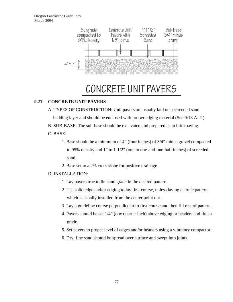
Oregon Landscape Guidelines March 2004
9.21 CONCRETE UNIT PAVERS
A. TYPES OF CONSTRUCTION: Unit pavers are usually laid on a screeded sand
bedding layer and should be enclosed with proper edging material (See 9:18 A. 2.).
B. SUB-BASE: The sub-base should be excavated and prepared as in brickpaving.
C. BASE:
1. Base should be a minimum of 4” (four inches) of 3/4” minus gravel compacted
to 95% density and 1” to 1-1/2” (one to one-and-one-half inches) of screeded
sand.
2. Base set to a 2% cross slope for positive drainage.
D. INSTALLATION:
1. Lay pavers true to line and grade in the desired pattern.
2. Use solid edge and/or edging to lay first course, unless laying a circle pattern
which is usually installed from the center point out.
3. Lay a guideline course perpendicular to first course and then fill rest of pattern.
4. Pavers should be set 1/4” (one quarter inch) above edging or headers and finish
grade.
5. Set pavers to proper level of edges and/or headers using a vibratory compactor.
6. Dry, fine sand should be spread over surface and swept into joints.
77
Oregon Landscape Guidelines March 2004
78
9.22 NATURAL STONE PAVING
A. TYPES OF CONSTRUCTION: Natural stone paving may be set with wet or dry
mortar joints, sand joints or soil joints. It may be mortared on a concrete bed, set on a
sand bed or a soil bed.
B. SUB-BASE
1. Area to be paved should be laid out true to line and grade with cross pitch
needed to assure proper drainage from finished surface.
2. Should be excavated to proper depth to allow for base and pavers.
3. Area should be free of organic matter, rocks over 3/4” (three quarter inch), and
clay lumps.
4. Sub-soil should be compacted to 90% relative density for non-vehicular areas
and 95% relative density for vehicular traffic areas.
C. BASE
1. Concrete base in areas with vehicular traffic should be a minimum of 4” (four
inches) of reinforced concrete over a minimum 2” (two inch) compacted sand
or 3/4” minus gravel sub-base or as per code and/or specifications.
2. Concrete base for non-vehicular areas should be a minimum of 2” (two inches)
of reinforced concrete laid over a 2” (two inch) sub-base of sand or 3/4” minus
gravel sub-base or as per code and/or specification.
3. Base for stone on sand should be a minimum of 3” (three inches) gravel
compacted to 95% density with plus-or-minus 1” (one inch) sand, having
enough variation in depth to accommodate the adjustments needed to place the
finished surface at an even plane with differing stone thicknesses. Sand should
be screeded level.
4. Base should be constructed with a 2% cross slope to direct drainage at surface.
D. REINFORCEMENT: Refer to section 8.13 CONCRETE PATIOS
E. INSTALLATION:
1. All stone should be laid true to line and grade in the desired pattern.
2. Stone laid into areas with fixed edges should be laid first in alignment with
such edges and then filled to the middle.
Oregon Landscape Guidelines March 2004
79
3. DRY MORTAR:
a. Stone laid first on sand or mortar bed over concrete base (best method).
b. Stones set with a maximum average joint space of 1/2” (one half inch).
Set stones with beveled edges with the bevel down to minimize size of
joints.
4. WET MORTAR:
a. Stone should be set on a mortar bed over a concrete base and allowed to
cure.
b. Place stones with joints 1/2” (one half inch) to 1” (one inch) wide.
Joints should be no more than a maximum 2” (two inches) wide.
c. Tap mortar mix into place to fill joints to specified level and finish as
specified.
d. Clean excess mortar from stone surface before drying and do not use
acid for cleaning natural stone.
5. SAND JOINTS:
a. Stone can be set with sand joints over a sand base or sand bed on a
concrete base.
b. Joints should average 1/2” (one half inch) or less and beveled edge of
stone should be placed down.
c. Stone should contact adjacent stone at least at three points to provide a
more stable surface.
d. Builders sand should be spread over finished surface and swept in
multiple directions to fill joints. After fill, spray surface and joints with
water to set sand.
e. In areas of frequent freeze-thaw patterns and/or wet-dry cycles, this
type of stone paving will heave and might have to be reset on a regular
basis.
6. SOIL JOINTS:
a. Stepping stones and stone paving designed to have plantings
interspersed may be laid on a compacted soil base.
Oregon Landscape Guidelines March 2004
80
b. Level of stone surfaces should be set on a gradual changing level or
level to avoid trip hazards.
c. Adjust width of joints to accommodate average stride distance between
stepping stones and/or width required to accommodate inter-plantings.
d. Joints should have a minimum width of 2” (two inches).
e. Joints should be filled to a depth that will bring plantings to the height
of stone surface.
f. Stone level and alignment should be checked yearly.
9.23 TILE PAVING
A. BASE: The base for tile paving should be the same as used for brick paving unless a
sand base is used, in which case, a 4” (four inch) compacted sand base should be
used.
B. REINFORCEMENT: Refer to section 8.13 CONCRETE PATIOS.
C. INSTALLATION:
1. All tile should be installed as per manufacturer and/or code specifications.
2. Tile should be laid true to line and grade in the specified pattern.
3. Tiles should be set on a wet mortar base.
4. Joints should be set as specified with a 1/2” (one half inch) maximum width.
5. Joints may be filled with mortar or weather proof grout as specified and
normally will be finished with a tooled joint.
Oregon Landscape Guidelines March 2004
81
10.0 WATER CONSERVATION
____________________________________________________________
10.01 DESCRIPTION
A. PURPOSE: As an industry, we recognize that water is in limited supply, and water
conservation should be practiced by all landscape professionals. The industry is
committed to protecting the environment and existing water supplies in the face of
increasing population and urban growth, and to saving our clients’ budgetary dollars
through water savings. The goal is to be proactive in water management practices
while installing and maintaining functional, aesthetically pleasing landscapes and
promoting value-added services to the landscapers’ customer base.
B. APPROACH: Four main phases in landscape work have a major effect on water use
and management:
1. Concept/design phase
2. Installation
3. Irrigation
4. Maintenance
At each phase of work, site conditions, design schemes, installation
procedures, and maintenance, should be thoroughly analyzed to assess
opportunities for better water management practices.
10.02 CONTRACTOR RESPONSIBILITY
CODES AND REGULATIONS: It is the responsibility of the Landscape Contractor to
comply with all applicable codes and regulations. The contractor should be proactive in
encouraging clients, designers and landscape architects to use water conservation, and
environmental protection techniques.
10.03 LANDSCAPE DESIGN PHASE
A. DESCRIPTION: Landscape design should implement water management. The design
of a landscape has long-term effects on water usage.
Oregon Landscape Guidelines March 2004
82
B. SITE ANALYSIS: Prior to design and/or installation, the contractor should be aware
of site information that impacts material selection, installation techniques,
environmental protection and water conservation. Such information may include:
1. Regional, local and micro-climates.
2. Soil conditions.
3. Slopes and Drainage Patterns.
4 .Existing vegetation: Analyze existing vegetation on site:
5. Landscape use: The proposed intent/use of the landscape being designed.
C. PLANT SELECTION:
1. Plants selected should be suitable for the hardiness/climatic regime of the site;
unless specified for specialized growing conditions. Plants should be selected
by water use classification for a given region.
2. Plants should be selected for site microclimates and hydrozones to provide
optimum growth potential and reduce water requirement.
3. Plants selection should be based on the proposed use of the various parts of the
landscape.
4. A portion of the criteria for selecting plants should include their irrigation
requirement.
10.04 INSTALLATION AND PLANTING
A. SITE PREPARATION: In preparation for plantings and installation of landscapes,
methods and techniques should promote good soil tilth:
1. Practice plant and site protection as set forth in section 2.02 GENERAL
REQUIREMENTS.
2. Whenever feasible do not work very wet or dry soils. If necessary to work in
such conditions, contractor should take measures to prevent compaction and
breakdown of soil structure.
3. If possible, keep all areas to be landscaped covered with vegetation and/or
mulch until they are worked to prevent erosion and loss of material.

Oregon Landscape Guidelines March 2004
83
4. In areas with soil conditions not conducive to good plant growth, and where
budget and time allow, provide drainage systems and use amendments to build
soil structure and texture.
B. PLANTING: Planting techniques should be practiced as in section 12.0 PLANTING
TECHNIQUES to promote healthy plantings.
10.05 WATERING AND IRRIGATION
A. WATERING: The contractor should advise the client as to watering practices relative
to hydrozones, timing, and quantity of water that should be applied.
B. IRRIGATION DESIGN AND LAYOUT
1. Design for efficient and uniform distribution of water.
2. Select appropriate equipment components that meet site and local code
requirements.
3. Design considerations should include soil type, slope, root depth, plant
materials, microclimates, water source, peak demands and watering windows.
C. INSTALLATION:
1. The installation shall conform to plans, designs and specifications.
2. Field changes should be considered.
3. Utility locates should be arranged, and all local code requirements met.
D. SCHEDULING:
The irrigation schedule should be changed as required to provide supplemental water to
maintain healthy plants and turf-grass without wasting the resource.
E. IRRIGATION SYSTEM MAINTENANCE:
1. The system shall be maintained to assure the integrity of the design.
2. Maintenance shall result in sustaining an efficient and even distribution of the
water.
10.06 LANDSCAPE MAINTENANCE
A. GOALS: The goal is to use good cultural practices to maintain plantings and soil
health at an optimum level in order to reduce the amount of water needed.

Oregon Landscape Guidelines March 2004
84
B. MAINTENANCE: Landscape maintenance should be practiced as in section 15.0
LANDSCAPE MAINTENANCE.
1. CRITICAL ASPECTS FOR WATER CONSERVATION
a. Maintenance of soil structure and soil health as in section 10.03
INSTALLATION AND PLANTING - A. SITE PREPARATION
b. Mulching open beds with 2-4” (two to four inches) of compost; or
organic mulch when organic fertilizer is added to offset nitrogen loss.
2. Avoid practices that stress plants and/or would require high water inputs.
3. Utilize mulch mowing practices to conserve water.
Oregon Landscape Guidelines March 2004
85
11.0 IRRIGATION
____________________________________________________________
11.01 DESCRIPTION
A. DEFINITION: A landscape irrigation system is any assemblage of equipment and
materials that are designed, manufactured and installed to deliver controlled
applications of water for landscape purposes.
B. WATER SOURCE: Water can be supplied from any safe and suitable source allowed
by code and/or regulation including wells, municipal water, ponds, rivers and
streams, and where deliverable and approved, treated wastewater.
C. USES: Irrigation systems may be used to supply supplemental water to all landscape
plantings, to control dust and/or erosion or other environmental controls in any and
all landscape areas.
11.02 WORK INCLUDED
This section includes all steps necessary in the selection of materials, proper installation,
system programming and scheduling, and maintenance.
A. SUPPLIES AND MATERIALS:
1. Pipe and fittings
2. Backflow prevention devices
3. Valves and valve boxes
4. Controllers and control circuits
5. Sprinkler heads and risers
6. Drip systems
7. Filtering systems
8. Check valves and anti-drain valves
9. Booster pumps/pumps
10. Moisture/rain sensors
B. SYSTEM DESIGN AND LAYOUT
C. INSTALLATION TECHNIQUES
D. PROGRAMMING AND SCHEDULING
E. MAINTENANCE
Oregon Landscape Guidelines March 2004
86
11.03 CONTRACTOR’SRESPONSIBILITY
A. CODES AND PERMITS: All irrigation systems and their installation should conform
to any national, state and/or local codes that apply, including permits and/or
inspections that may be required.
B. LICENSING: Any person installing irrigation systems, other than minor head
replacement and repair, must be a licensed Landscape Irrigation Contractor
(otherwise referred to as contractor in this section) and must have a LBDI (Limited
Backflow Device Installer) license if installing a backflow prevention device. Refer
to ORS (Oregon Revised Statute) and OAR (Oregon Administrative Rules) for
detailed information.
11.04 REFERENCES
There are two state codes that establish minimum application and installation standards
for backflow devices in Oregon:
A. The Oregon Administrative Rules (OAR).
B. The Uniform Plumbing Code (UPC).
11.05 SUBMITTALS
A. AS-BUILT DRAWINGS: The contractor should furnish the client with accurate, up to
date drawings when a project is finished that include any changes that might have
been made during installation (changes to original plans and contracts should have
been approved in writing prior to the actual changes) if required by contract.
B. OPERATION AND MAINTENANCE/WARRANTY DATA:
1. Upon completion of the installation and setup of the system, contractor should
furnish to the client all manufacture information and warranties.
2. When manufacturers’ information is not available, contractor should furnish
client with directions for operation of systems, including controller schedules.
11.06 EXISTING CONDITIONS
The installation of irrigation systems should not exceed minimal disturbance of existing
site improvements and/or vegetation unless approved in advance:
Oregon Landscape Guidelines March 2004
87
A. PAVING AND STRUCTURES: Existing paving and structures should not be
disturbed in the installation of irrigation systems if at all possible. Piping should be
run in sleeves placed by boring beneath the base of pavements and, in cases where
boring is not feasible, the pavement or structure should be replaced to as near as
original as possible. Such work and the compensation for the work should be agreed
to in written contract prior to commencement.
B. EXISTING VEGETATION: Mechanical trenching and pipe pulling should not
be allowed in the rootzones of existing plants. Smaller plants that will not be
damaged by operations, can be lifted and held until irrigation trenching is done. With
larger plants, all effort should be made to run piping outside of root zones. When not
possible, use boring techniques to run piping.
11.07 SCHEDULING
A. SLEEVES: Contractor should arrange for, and/or install, sleeves for irrigation piping
prior to the commencement of construction on all paving and walls.
B. CONSTRUCTION PHASE: Irrigation piping and risers should be installed, whenever
possible, after rough grading. Heads and final adjustments should be
installed/completed after finish grading.
11.08 SUBSTITUTIONS
All substitutions of product should be of equal or greater quality, should perform equal to
or better than original design specifications, and should be approved by owner or owner’s
representative.
11.09 WARRANTY
A. CONTRACTOR RESPONSIBILITY: Upon completion and testing of the system the
contractor should provide in writing and demonstrate to the client how to monitor,
adjust and schedule all parts of the system.
B. MANUFACTURER’S WARRANTY: All manufacturers’ and supplier warranties
should be explained and presented to the client or client’s representative at the time of
completion.
Oregon Landscape Guidelines March 2004
88
C. PERFORMANCE WARRANTY: A warranty shall be provided covering
workmanship and materials for a period of 1 (one) year following completion of the
installation.
11.10 MATERIALS/PRODUCTS
A. RIGID PVC: All rigid polyvinyl chloride pipe (PVC) should conform to ASTM
standards for PVC 1120, PVC 1120 (type 1) or PVC 2120 (type 2) and should be
National Sanitation Foundation (NSF) approved.
1. CONSTANT PRESSURE/MAIN LINE: All main line piping (under constant
pressure) using solvent weld joints should be Class 200 or better, in sizes up to
4” (four inches). Pipe over 4” (four inches) should be Class 200 ring or gasket
joint pipe. All piping 4” (four inches) and larger should have proper thrust
blocking.
2. LATERAL PIPE: Piping downtstream of operating valves, not subject to
constant pressure, should be a minimum of Class 200 PVC.
3. FITTINGS: Fittings for rigid PVC pipe should be solvent weld, ring or gasket
joint, or IPS (Iron Pipe Size) threaded. Heavy wall PVC nipples, Schedule 80
with molded threads can be used.
a. SOLVENT WELD: Fittings should be socket type PVC Shedule 40.
b. RING OR GASKET: Fittings should be of a type compatible to the pipe
used and recommended for use by the manufacturer.
c. COMPRESSION: Fittings should be of a size and type compatible with
PVC pipe and pressure rated to meet and/or exceed the pressure
requirements of the system.
d. THREADED: All fittings for threaded joints should match IPS sizing
and should be threaded schedule 40.
e. THREADED NIPPLES: All rigid nipples used in threaded assemblies
should be PVC Shedule 80 with molded IPS threads.
Oregon Landscape Guidelines March 2004
89
B. FLEXIBLE PLASTIC:
1. PIPE: All flexible plastic pipe should be polyethylene (PE) PE 2306, PE 3306,
or PE 3406 Class 125 or greater as required to meet the pressure requirements
of the system.
2. FITTINGS: Fittings should be insert or compression type designed to use with
PE pipe. Fittings should meet the pressure requirements of the system and
should use fastening systems designated by the manufacture for such use.
C. GALVANIZED STEEL: Due to hydraulic characteristics, cost and propensity to
corrosion, galvanized steel should not be used unless specifically called for by code,
regulation and/or specification.
1. PIPE: All steel pipe should be Schedule 40 standard steel pipe.
2. FITTINGS: Should be standard malleable standard steel with IPS threads.
3. NIPPLES: Nipples should be threaded Schedule 40 standard steel pipe unless
specified otherwise.
D. COPPER:
1. PIPE: All piping should be Type L copper tube.
2. FITTINGS: Fittings should be standard solder type wrought copper or cast
bronze, 150 psi. Connections between copper and standard steel should utilize
bimetal, non-corrosive fittings.
11.11 BACKLOW PREVENTION ASSEMBLIES
A. DESCRIPTION: Backflow prevention prevents the backflow of contaminated water
from irrigation systems into domestic water supplies.
1. Backflow can occur through any “cross connection” between irrigation systems
and potable water systems.
2. “Cross Connections” are defined as any actual or potential connection in a
water system where contaminating material can come in contact with a potable
water supply.
3. Backflow can occur in two ways:
a. BACKSIPHONAGE: Occurs when the supply pressure is interrupted
and a negative pressure or siphon occurs.
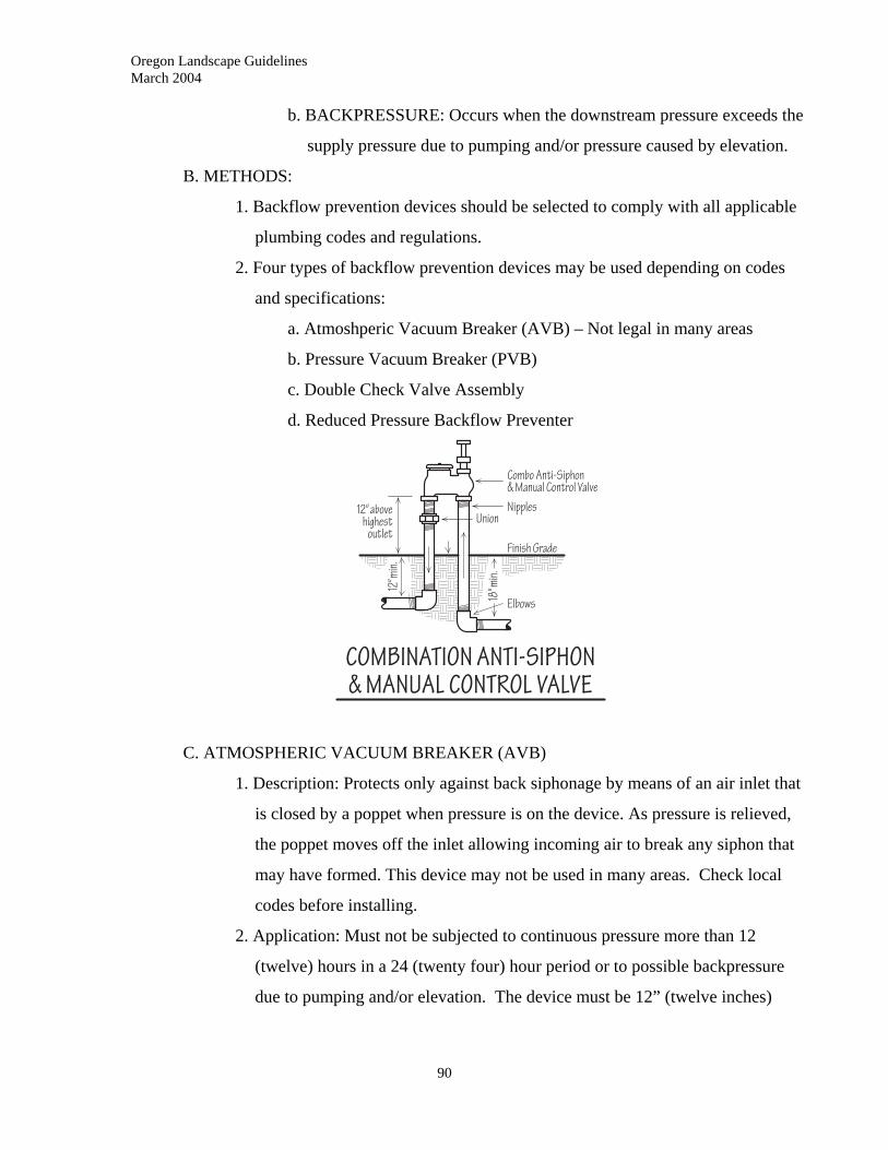
Oregon Landscape Guidelines March 2004
b. BACKPRESSURE: Occurs when the downstream pressure exceeds the
supply pressure due to pumping and/or pressure caused by elevation.
B. METHODS:
1. Backflow prevention devices should be selected to comply with all applicable
plumbing codes and regulations.
2. Four types of backflow prevention devices may be used depending on codes
and specifications:
a. Atmoshperic Vacuum Breaker (AVB) – Not legal in many areas
b. Pressure Vacuum Breaker (PVB)
c. Double Check Valve Assembly
d. Reduced Pressure Backflow Preventer
C. ATMOSPHERIC VACUUM BREAKER (AVB)
1. Description: Protects only against back siphonage by means of an air inlet that
is closed by a poppet when pressure is on the device. As pressure is relieved,
the poppet moves off the inlet allowing incoming air to break any siphon that
may have formed. This device may not be used in many areas. Check local
codes before installing.
2. Application: Must not be subjected to continuous pressure more than 12
(twelve) hours in a 24 (twenty four) hour period or to possible backpressure
due to pumping and/or elevation. The device must be 12” (twelve inches)
90

Oregon Landscape Guidelines March 2004
higher than the highest head in the circuit. Pipe nipples connecting device to
mainline must be set vertically.
3. Has to be placed on the downstream side of control valves.
4. This section also refers to combination control valve and AVB equipment.
5. Must be protected from freezing when necessary.
D. PRESSURE VACUUM BREAKER (PVB)
1. Description: Protects against back siphonage by means of a check valve and an
air inlet, which is closed when pressure is on the device. The poppet closing
the air inlet is spring loaded which insures it will open even after being under
pressure for long periods.
2. Application: Can be placed under continuous pressure. Will not function with
back pressure from pumping or elevation. Has to be placed 12” (twelve)
inches higher than the highest point in the irrigation system. Pipe nipples
connecting device to mainline must be set vertically.
3. Can be placed before control valves requiring only one device for entire
system.
4. Should not be installed where any toxic substances may backflow.
5. Must be tested at time of installation, after repair, when relocated and at least
annually after installation by a certified backflow assembly tester.
91
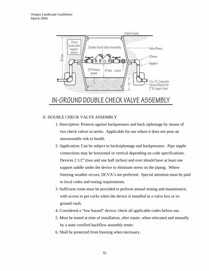
Oregon Landscape Guidelines March 2004
E. DOUBLE CHECK VALVE ASSEMBLY
1. Description: Protects against backpressure and back siphonage by means of
two check valves in series. Applicable for use where it does not pose an
unreasonable risk to health.
2. Application: Can be subject to backsiphonage and backpressure. Pipe nipple
connections may be horizontal or vertical depending on code specifications.
Devices 2 1/2” (two and one half inches) and over should have at least one
support saddle under the device to eliminate stress on the piping. Where
freezing weather occurs, DCVA’s are preferred. Special attention must be paid
to local codes and testing requirements.
3. Sufficient room must be provided to perform annual testing and maintenance,
with access to pet cocks when the device is installed in a valve box or in-
ground vault.
4. Considered a “low hazard” device; check all applicable codes before use.
5. Must be tested at time of installation, after repair, when relocated and annually
by a state certified backflow assembly tester.
6. Shall be protected from freezing when necessary.
92
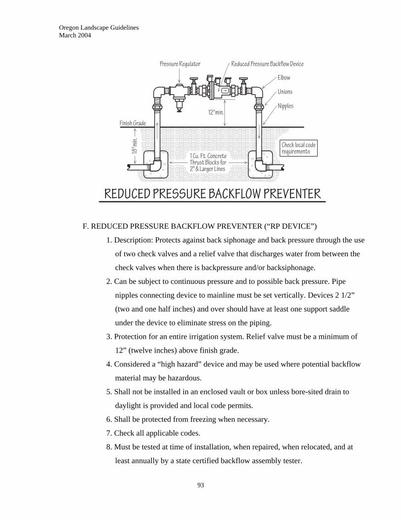
Oregon Landscape Guidelines March 2004
F. REDUCED PRESSURE BACKFLOW PREVENTER (“RP DEVICE”)
1. Description: Protects against back siphonage and back pressure through the use
of two check valves and a relief valve that discharges water from between the
check valves when there is backpressure and/or backsiphonage.
2. Can be subject to continuous pressure and to possible back pressure. Pipe
nipples connecting device to mainline must be set vertically. Devices 2 1/2”
(two and one half inches) and over should have at least one support saddle
under the device to eliminate stress on the piping.
3. Protection for an entire irrigation system. Relief valve must be a minimum of
12” (twelve inches) above finish grade.
4. Considered a “high hazard” device and may be used where potential backflow
material may be hazardous.
5. Shall not be installed in an enclosed vault or box unless bore-sited drain to
daylight is provided and local code permits.
6. Shall be protected from freezing when necessary.
7. Check all applicable codes.
8. Must be tested at time of installation, when repaired, when relocated, and at
least annually by a state certified backflow assembly tester.
93
Oregon Landscape Guidelines March 2004
94
11.12 VALVES AND VALVE BOXES
A. QUICK COUPLER VALVES:
1. Quick coupler valves are normally pressurized to the valve, and mounted flush
with finish grade or in a valve box.
2. Activated by a key, generally with a sprinkler or hose bib attached.
3. Provide with winterization points.
B. MANUAL VALVES: MAIN, GLOBE, ANGLE, SPRINKLER AND
COMBINATION ANTI-SIPHON: These valves stop and start an irrigation circuit
and control pressure downstream from the valve location. Contractor should suggest
use of automated valves to promote water conservation.
C. MANUAL VALVES: MAIN SHUT-OFF or ISOLATION: Purpose is to isolate and
control the entire irrigation system or a portion thereof. The main requirement for
these valves are low flow losses and infrequent cycling (on and off).
D. CHECK VALVES: Horizontal or vertical, spring loaded valves allowing flow of
liquid in one direction only.
E. PRESSURE REGULATING VALVES: Installed to automatically maintain a set
operating pressure and/or flow downtstream.
F. REMOTE CONTROL VALVES: Devices that are used to control the flow of
irrigation water and are activated from a remote source. Most control valves are
electric types with the controlling signal coming from a controller via wire. One
valve is used for each irrigation zone or circuit.
G. VALVE BOXES: Concrete or Plastic boxes designed to house valves, preventing their
burial in soil and allowing access for adjustment, testing, manual operation and/or
repair. Can house single or multiple valves.
11.13 CONTROLLER AND CONTROLLER CIRCUITS
A. AUTOMATIC IRRIGATION CONTROLLERS: Any automatic timing device
used to control irrigation zones by activation of remote control valves on a
predetermined schedule. Types:
1. Hydraulic: seldom used except in specialty situations
2. Electric: mechanical control knobs
Oregon Landscape Guidelines March 2004
95
3. Electric: electronic or solid-state touch pad, includes memory and multiple
functions
4. Electric: computer driven combined with radio signal
5. Solar powered
6. Hybrid combination controllers
7. Battery powered
B. CIRCUITS: Any combination of conductors used to transmit hydraulic or electrical
energy.
C. IRRIGATION CONTROL CIRCUITS: Any electrical circuit that controls the
operation of remote landscape irrigation equipment by supplying signals and/or
power to a solenoid, thermal motor, clock motor, or actuating device.
D. CONTROLLER OUTPUT CIRCUITS: Output circuits for irrigation systems must be
power-limited remote control for signaling and activating remote control valves.
1. Limited power source should be one of the following:
a. A transformer approved for the purpose
b. A primary battery
c. Other inherently limited power source approved for this purpose.
2. Irrigation control circuits should be supplied by a limited power source to the
following levels:
Circuit Voltage - Vmax --------------30 VAC
Volt Amperes - VA-------------------100 VA
Current - I -----------------------------100/Vmax
Current Limitation - Imax-------------5.0 Amps
E. CONDUCTORS: Any wire or cable for carrying electrical current:
1. Conductors on the load side of transformer should be no smaller than #14 if
single conductor and #18 if multiple conductor for physical strength, and
should be:
a. Type UF cable rated at 600 volts as per U/L standard number 493.
b. Polyethelene-insulated golf course and irrigation system wire for direct
burial rated at 300 volts per U/L Miscellaneous wires.
Oregon Landscape Guidelines March 2004
96
c. Other approved cable suitable for direct burial in the earth, which is
rated at not less than 300 volts with a covering that is moisture, fungus
and sunlight resistant and has an insulation thickness of not less than 30
mils.
F. CONDUIT (SLEEVE): A tube, pipe or other enclosure through which electrical wires
or piping is run to provide accessibility and/or protection from physical damage.
Type should be selected as per code and/or specification.
11.14 SPRINKLER HEADS, RISERS AND ANTI-DRAIN VALVES
A. DEFINITIONS:
1. ARC OF COVERAGE: The angle of coverage of a sprinklers nozzle or pattern
expressed in degrees (90, 120, etc), or as part of a circle, quarter spray etc.
2. CAP: Top of a sprinkler; usaually the pop-up type.
3. CASE: The exterior shell or body of the sprinkler
4. CUT-OFF RISER: A nipple, usually of polyethylene material, with several
threaded sections that can be cut off to adust nipple height. Seldom used in
professional applications.
5. FLEX RISER: A riser made of flexible material so it can be bent without
breaking. Usually used for mounting small sprinklers to avoid damage to
lateral pipe.
6. POSITIVE RETRACTION: Feature of a pop-up type sprinkler that returns it to
the non-operating retracted position by means of a spring.
7. RADIUS: The distance water is thrown from the nozzle.
B. SPRINKLER HEADS: A mechanism used to deliver water to the landscape.
1. NOZZLE: Portion of sprinkler that can determine the pattern of spray, the arc
of coverage, and the radius of coverage. Patterns may be fixed, solid arcs of
coverage (i.e. half), stream sprays or bubblers.
2. BUBBLERS: Used for small areas or individual plants; delivers water in a
series of small streams or a small fountain pattern. Mounted above grade.
3. FIXED SPRAY: Heads mounted as pop-ups or above grade that deliver water
to the entire area on a continual basis. May have adjustable nozzles, stream or
Oregon Landscape Guidelines March 2004
97
spray patterns, and generally operate at lower operating pressures; low to
medium flow requirements and medium to high precipitation rates.
4. POP-UP: A sprinkler that has the nozzle mounted on a stem that riser above the
body of the sprinkler when under pressure.
5. ROTARY SPRINKLER: Gear driven or impact driven, a sprinkler in which a
stream or multiple streams of water are rotated over the arc of coverage.
Generally covers larger areas with lower precipitation rates.
6. SHRUB HEADS: Sprinklers, usually set on fixed risers above vegetation, used
to irrigate shrub areas.
C. RISERS: When describing a sprinkler, it is the stem to which the sprinkler body is
attached. Risers can be schedule 80 PVC, polyethylene, galvanized steel or marlex.
In pop-up sprinklers, it is the pop-up stem to which the nozzle is attached.
D. SWING JOINTS AND FLEX RISERS: Used to provide protection to lateral piping
when sprinklers are subjected to impact.
1. SWING JOINTS: Joints between the lateral pipe and sprinkler bodies or joints
between mainline pipe and quick coupling valves. Generally made up of a
combination of nipples and threaded fittings; can be single, double or triple
joints.
2. FLEX NIPPLES OR RISERS: Manufactured from PVC hose with fixed
threaded fittings or polyethylene hose with barbed, insert fittings and hose
clamps along with threaded IPS fittings (“funny-pipe”).
E. ANTI-DRAIN VALVES: Used to prevent low head drainage on lateral lines. Check
valves that are spring loaded; opening under pressure and closing by spring action
when pressure drops.
11.15 BOOSTER PUMPS
A. Placed into mainlines to increase existing pressure to a higher pressure at a given
flow.
B. Boosters pumps are typically electrical centrifugal pumps that operate at 230/460
volts.
Oregon Landscape Guidelines March 2004
98
11.16 SOIL MOISTURE SENSING EQUIPMENT
A. APPLICATION: Monitors soil moisture in relation to plant needs and overrides the
pre-programmed schedule of the controller. Manual sensors that do not override the
controller can be used to establish optimum scheduling/programming.
B. TYPES: Two basic categories are used:
1. TENSIOMETERS: Hollow water filled tubes with a ceramic sensing tip and a
sealed vacuum gauge. Inserted in the soil, measures soil water matrix potential
on a direct basis. (manual measurement to aid programming).
2. ELECTRICAL RESISTANCE DEVICES: Use electrodes encased in porous
material (usually gypsum) to measure soil water potential and to activate
controller cycles when soil moisture drops to temporary wilting point.
11.17 RAIN SENSORS
A. Sensors that monitor rainfall and interrupt normal controller cycles when rainfall
exceeds a preset amount.
11.18 DRIP IRRIGATION COMPONENTS
A. VALVES: Manual or remote control valves adjustable to, or designed to operate at,
low flow rates and operating pressures.
B. FILTRATION: Most drip or low volume irrigation systems require filtration because
of the minute orifice openings used to disperse water. Most manufactures specify
mesh or micron requirements for filtration.
1. MESH: Number of openings per lineal inch
2. MICRON: Equal to one millionth of a meter.
C. TUBING/PIPING
1. Mainline piping normally PVC, laterals and delivery tubing usually poly.
2. POLYETHYLENE: Polyethylene resin tubing that is flexible. Quality piping
treated with UV inhibitors.
3. PVC (Polyvinyl Chloride) FLEXIBLE TUBING: Not as flexible as poly. Used
where mechanical damage and/or rodent damage are problems.
Oregon Landscape Guidelines March 2004
99
4. TUBING REQUIREMENTS:
a. I.D. and O.D. must be published for each tubing type.
b. Tubing must be of a material that resists the growth of algae on the
inside.
c. Temperature extremes: maximum 140 degrees C. minimum water
temperature to -40 degrees C. freezing.
d. All tubing and fittings must be installed as per manufacturer
specifications.
D. FITTINGS:
1. POLYETHYLENE TUBING:
a. Compression: fittings that slide over tubing and through the use of
gaskets grip the outside. Designs allow use with pressures up to 90 psi.
b. Barbed insert: slip inside pipe and use pipe clamps on larger tubing
sizes. Pressure usually limited to 80 psi maximum.
2. PVC TUBING: Solvent weld schedule 40 PVC fittings usually used unless
special fittings are specified by manufacturer.
3. FITTING REQUIREMENTS:
a. Must specify tubing to be used by I.D. or O.D. depending on tubing
type.
b. Must withstand design pressure of system
c. Temperature extremes: maximum 140 degrees C. minimum water
temperature to -40 degrees C. freezing.
E. EMISSION/WATER DELIVERY PRODUCTS
1. EMITTERS: Single or multiple orifices that deliver water in “drip” form with
flows measured in GPH (gallons per hour). Operate at low pressures.
a. Compensating: devices that compensate for pressure fluctuations due to
elevation changes.
b. Non-compensating: devices that do not compensate for pressure
fluctuations.
2. MIST SPRAYERS: Used in specialty plantings and situations; emit a fine mist
to increase air moisture.
Oregon Landscape Guidelines March 2004
100
3. SOAKERS: Perforated or porous tubing used to deliver water fairly evenly
along the entire lenth of the tube.
a. Multi-chamber: Water flows through the main center of tubing and is
dispensed through a lower pressure chamber or chambers. Outlet
spacing is usually in the range of 6” to 24” (six to twenty four inches).
b. Single chamber: Water flows along the tubing and is dispensed through
holes drilled by laser in the chamber wall or emitters in-line. Outlet
spacing is usually in the range of 6” to 24” (six to twenty four inches).
4. POROUS: Tubing extruded from porous material that allows the entire tube to
weep.
5. EMISSION DEVICE REQUIREMENTS:
a. Must have published flow rates at specific water pressure.
b. Minimum and maximum operating pressure must be published
c. Devices must be self-purging or easily cleaned in field.
d. Must be capable of deterring the entry of insects.
11.19 OTHER IRRIGATION PRODUCTS AND MATERIALS
The proper assemblage of an irrigation system requires the use of other materials such as
PVC solvent, copper flux and solder, teflon tape and wire connectors. All materials
should be selected and used as per manufacturers’ specifications.
11.20 SYSTEM LAYOUT
Exact location of sprinkler heads, pipe routing, valves, backflow devices and controller
locations should be clearly marked and confirmed on-site prior to work.
11.21 TRENCHING AND BACKFILL
A. TRENCHING PROCEDURES:
1. Locates should be made prior to any trenching.
2. Trenches should be dug in relatively straight lines with vertical sides and with
bottoms smooth and level. May be machine or hand dug.
Oregon Landscape Guidelines March 2004
101
3. Trench width should be wide enough for easy installation of pipe and/or wire
and allow enough width to snake PVC pipe in gradual “S” curves to allow for
expansion and contraction. Minimum size should be 2 1/2 (two and one half)
the diameter of pipe.
4. Trench depth: Should conform to all regulations and codes. Generally in
commercial and residential work mainline pipe should have 18-24” (eighteen
to twenty four inches) of cover over the pipe and lateral pipe should have 12-
18” (twelve to eighteen inches) of cover. In areas where ground conditions do
not allow full trenching depths, cover should be placed over pipe.
B. PIPE PULLING:
1. In areas where soil conditions permit, pipe up to 2” (two inches), with a
minimum wall thickness of class 200 PVC, may be pulled into soil with proper
vibratory plow equipment eliminating the need to trench.
2. Locates should still be made.
3. Areas where equipment and fitting connections need to be made should be dug
the depth of the lateral or mainline being constructed and should provide
sufficient clearance along the pipe length to make proper connections.
C. DRILLING AND BORING:
1. Conduit can be installed under existing pavement to serve as a sleeve for
running piping and/or irrigation wiring. Approved jacking or drilling methods
may be used.
2. Jacking/drilling pits should be kept back a minimum of 2’ (two feet) from edge
of paving.
3. Excessive use of water that would soften sub-grade or undermine paving
should not be allowed.
4. Conduit should be placed below base material of paving.
5. Utility locates should be made prior to drilling or boring
D. BACKFILL:
1. All lumber, rocks and debris should be removed from trenches and backfill
material.
2. Pipe should have a firm, uniform bedding along its entire length.
Oregon Landscape Guidelines March 2004
102
3. In areas that are rocky, pipe should be laid on a minimum 2” (two inch) sand
base or clean, rock-free native soil and covered with 4” of sand or clean, rock-
free native soil.
4. Trenches should be backfilled with excavated soil after pipe and wire are
installed and pressure checked where required. The backfill should be
compacted to the density of the surrounding soil.
11.22 SLEEVES
A. APPLICATION: Irrigation sleeves should be installed under all site structures prior to
the laying of the base material to allow the running of pipe without disturbing the
finished work.
B. MATERIAL: Sleeves should be a minimum of class 200 PVC and sized to allow the
size of pipe and fittings designed for the irrigation system to pass through easily.
Where possible, provide separate sleeves for pipe and wiring.
C. DEPTH AND LENGTH: Sleeves should have a minimum of 8” (eight inches) of
cover between the sleeve and the structure; should be below the base material and at
the level of the piping. The length of the sleeve should extend 12” (twelve inches)
beyond the sides of the structure.
11.23 PIPE AND FITTINGS
A. HANDLING AND STORAGE: Pipe and fittings should be stored and handled in a
manner that would protect it from damage. Pipe storage should conform to OSHA
regulations and should protect piping from UV damage.
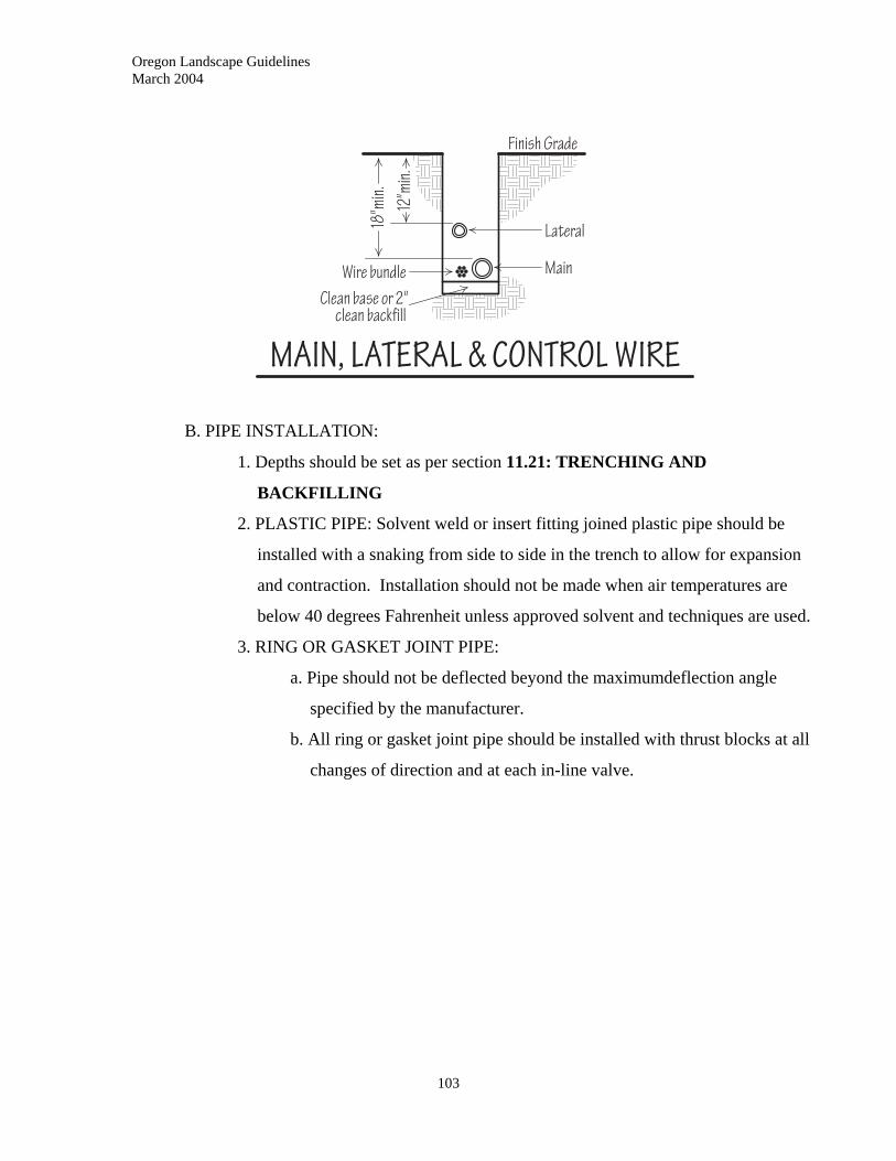
Oregon Landscape Guidelines March 2004
B. PIPE INSTALLATION:
1. Depths should be set as per section 11.21: TRENCHING AND
BACKFILLING
2. PLASTIC PIPE: Solvent weld or insert fitting joined plastic pipe should be
installed with a snaking from side to side in the trench to allow for expansion
and contraction. Installation should not be made when air temperatures are
below 40 degrees Fahrenheit unless approved solvent and techniques are used.
3. RING OR GASKET JOINT PIPE:
a. Pipe should not be deflected beyond the maximumdeflection angle
specified by the manufacturer.
b. All ring or gasket joint pipe should be installed with thrust blocks at all
changes of direction and at each in-line valve.
103
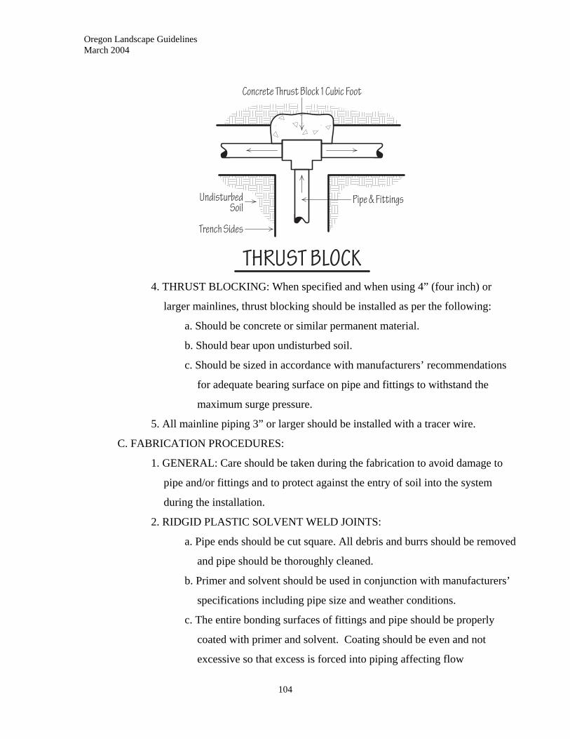
Oregon Landscape Guidelines March 2004
4. THRUST BLOCKING: When specified and when using 4” (four inch) or
larger mainlines, thrust blocking should be installed as per the following:
a. Should be concrete or similar permanent material.
b. Should bear upon undisturbed soil.
c. Should be sized in accordance with manufacturers’ recommendations
for adequate bearing surface on pipe and fittings to withstand the
maximum surge pressure.
5. All mainline piping 3” or larger should be installed with a tracer wire.
C. FABRICATION PROCEDURES:
1. GENERAL: Care should be taken during the fabrication to avoid damage to
pipe and/or fittings and to protect against the entry of soil into the system
during the installation.
2. RIDGID PLASTIC SOLVENT WELD JOINTS:
a. Pipe ends should be cut square. All debris and burrs should be removed
and pipe should be thoroughly cleaned.
b. Primer and solvent should be used in conjunction with manufacturers’
specifications including pipe size and weather conditions.
c. The entire bonding surfaces of fittings and pipe should be properly
coated with primer and solvent. Coating should be even and not
excessive so that excess is forced into piping affecting flow
104
Oregon Landscape Guidelines March 2004
105
characteristics. Excess materials should be wiped clean from pipe after
insertion in fittings.
d. Pipe should be inserted into the fitting to the shoulder, rotated about one
quarter turn and held in position until the solvent is set.
3. RIDGID PVC THREADED JOINTS: Threads should be wrapped with teflon
tape (except swing-joints) prior to installation unless otherwise specified for
specific applications. Joints should be tightened to fit snugly but not over-
tightened to prevent splitting of female fittings.
4. FLEXIBLE PLASTIC JOINTS: Manufacturer’s specifications for particular
type of fittings should be carefully followed. See setion 11.18: DRIP
IRRIGATION COMPONENTS. Pipe should be cut square and pressed on
fittings to the fitting stops.
5. GALVANIZED STEEL JOINTS: Pipe threads should be cleanly cut; all burrs
and debris removed and teflon taped or coated with a pipe sealing compound
as per as specifications prior to installation.
6. COPPER JOINTS: Copper pipe should be cut clean and square with a wheel
type cutter; burrs and debris removed; and coated with the appropriate copper
flux before joining. Pipe should be inserted firmly into the fitting stop; pipe
and fitting uniformly heated until solder is uniformly drawn into the joint
forming a bead at the outer edge. Connections to steel pipe should be made
with bimetal connectors to prevent corrosion.
D. FLUSHING: All main and lateral lines should be thoroughly flushed of debris and soil
prior to installation of valves and sprinkler devices.
11.24 BACKFLOW PREVENTION DEVICE – INSTALLATION
A. GENERAL INSTALLATION REQUIREMENTS:
1. CONTRACTOR RESPONSIBILTY: Installation must be made by a properly
licensed plumber or a landscape contractor licensed for irrigation and LBDI
(Limited Backflow Device Installer).
2. LOCATION: Device must be installed as per section 11.12: BACKFLOW
PREVENTION DEVICES. Where practical devices should be installed in
Oregon Landscape Guidelines March 2004
106
areas where they do not stand out in the landscape and where they are not
prone to physical damage. In areas where physical damage or vandalism might
be possible, devices should be placed in protective expanded metal cages that
can be locked.
3. PROPER POSITIONING: All devices should be installed as per code and to
allow easy access for attachment of testing devices, visual inspection and/or
maintenance. Also check with local water purveyor.
4. FREEZE PROTECTION: All devices must be installed in such a manner that
freeze protection procedures can be initiated without interfering with proper
operation of devices.
5. SPECIFIC APPLICATIONS: See section 11.11: BACKFLOW
PREVENTION DEVICES.
11.25 VALVES AND VALVE BOXES INSTALLATION
A. QUICK COUPLER VALVES:
1. LOCATION: If possible, should be installed outside turf areas to prevent
damage and to protect turf users.
2. DEPTH/HEIGHT: Generally should be placed slightly above grade to prevent
entry of dirt and /or debris when used. Should be placed 2” (two inches) above
grade in open beds or mulched areas.
3. If placed higher than two inches above grade, vertical connection to valve
should be staked and clamped to steel rebar stake to limit movement in use.
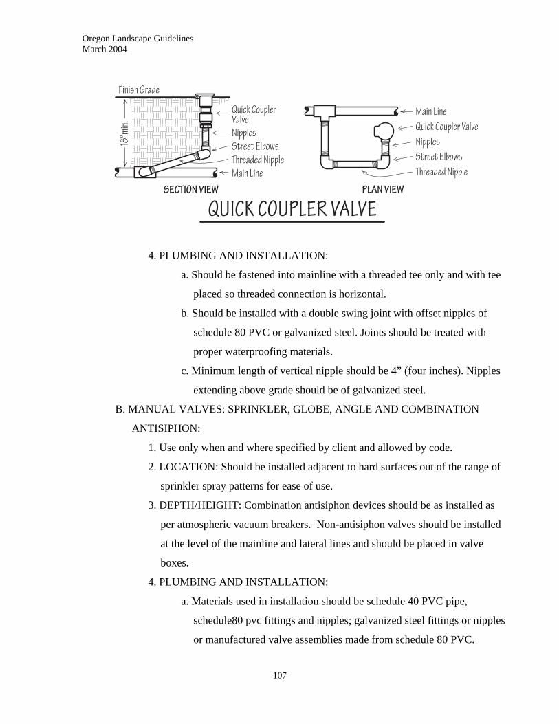
Oregon Landscape Guidelines March 2004
4. PLUMBING AND INSTALLATION:
a. Should be fastened into mainline with a threaded tee only and with tee
placed so threaded connection is horizontal.
b. Should be installed with a double swing joint with offset nipples of
schedule 80 PVC or galvanized steel. Joints should be treated with
proper waterproofing materials.
c. Minimum length of vertical nipple should be 4” (four inches). Nipples
extending above grade should be of galvanized steel.
B. MANUAL VALVES: SPRINKLER, GLOBE, ANGLE AND COMBINATION
ANTISIPHON:
1. Use only when and where specified by client and allowed by code.
2. LOCATION: Should be installed adjacent to hard surfaces out of the range of
sprinkler spray patterns for ease of use.
3. DEPTH/HEIGHT: Combination antisiphon devices should be as installed as
per atmospheric vacuum breakers. Non-antisiphon valves should be installed
at the level of the mainline and lateral lines and should be placed in valve
boxes.
4. PLUMBING AND INSTALLATION:
a. Materials used in installation should be schedule 40 PVC pipe,
schedule80 pvc fittings and nipples; galvanized steel fittings or nipples
or manufactured valve assemblies made from schedule 80 PVC.
107
Oregon Landscape Guidelines March 2004
108
b. When assembled into multiple valve assemblies or manifolds, valves
should be placed a minimum of 5” (five inches) apart to permit valve
removal without having to remove entire manifold. When using
galvanized nipples and fittings, unions should be used to facilitate
repairs.
c. Flush valves installed without valve boxes should have sleeves (or valve
collars) with covers installed to extend flush to finish grade. Sleeves
should be a minimum of 6” (six inch) diameter for hand operated
valves or 3” (three inch) diameter for valves operated by a sprinkler
key.
C. MANUAL VALVES: MAIN SHUT-OFF AND ISOLATION VALVES
1. PURPOSE: Used to isolate the irrigation system from water supply.
2. LOCATION: System should have at least one shut-off valve located at the
point of connection the water supply line.
3. A master electric control valve may be used in place of a gate valve for main
shut-off. Backflow devices should not be used as main shut-off valves.
4. DEPTH: Should be set at the depth of the mainline.
5. PLUMBING AND INSTALLATION: Should be installed in a valve box with
extensions to final grade when needed for manual operation.
6. IDENTIFICATION: Valve boxes for main shut-off valves should be clearly
and permanently marked on the cover.
D. PRESSURE REGULATING VALVES:
1. LOCATION: Need to be placed in mainline on the pressure side of control
(upstream side) valves. Should be placed in valve boxes. For drip irrigation
applications, a pressure regulator may be placed on the downstream side of the
control valve.
2. DEPTH: Install as per code regulations; usually at depth of mainline.
3. PLUMBING AND INSTALLATION:
a. Should use unions or flanged connections for ease in repair.
b. Provide minimum 4” (four inch) gravel base under valve box for
drainage.
Oregon Landscape Guidelines March 2004
109
E. REMOTE CONTROL VALVES:
1. LOCATION:
a. Should be installed at locations that provide the best hydraulic balance
(near the center of the zone) when needed and/or possible. If possible
locate outside of turf areas.
b. Should be installed in valve box and where possible located outside the
spray pattern of the sprinklers.
2. DEPTH: Should be installed at level of lateral piping; should not exceed 20”
(twenty inches) in depth.
3. PLUMBING AND INSTALLATION:
a. Remote control valves should not be direct buried.
b. All valves should have a minimum 2” (two inch) clearance from walls
of valve boxes and other valves.
c. When valve boxes are open, should have unlimited vertical clearance.
d. When assembled into multiple-valve assemblies or manifolds, valves
should be placed to permit removal of individual valves.
e. All valves equipped with flow control mechanisms should be easily
accessed from the top of the box.
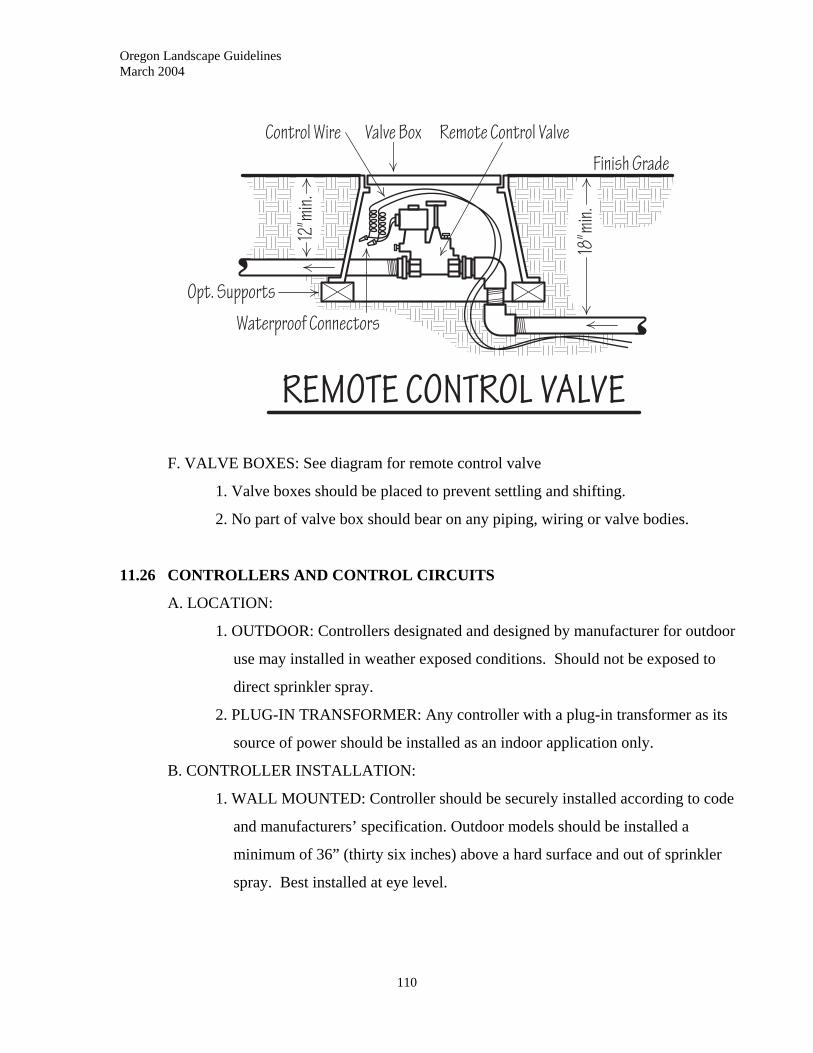
Oregon Landscape Guidelines March 2004
F. VALVE BOXES: See diagram for remote control valve
1. Valve boxes should be placed to prevent settling and shifting.
2. No part of valve box should bear on any piping, wiring or valve bodies.
11.26 CONTROLLERS AND CONTROL CIRCUITS
A. LOCATION:
1. OUTDOOR: Controllers designated and designed by manufacturer for outdoor
use may installed in weather exposed conditions. Should not be exposed to
direct sprinkler spray.
2. PLUG-IN TRANSFORMER: Any controller with a plug-in transformer as its
source of power should be installed as an indoor application only.
B. CONTROLLER INSTALLATION:
1. WALL MOUNTED: Controller should be securely installed according to code
and manufacturers’ specification. Outdoor models should be installed a
minimum of 36” (thirty six inches) above a hard surface and out of sprinkler
spray. Best installed at eye level.
110
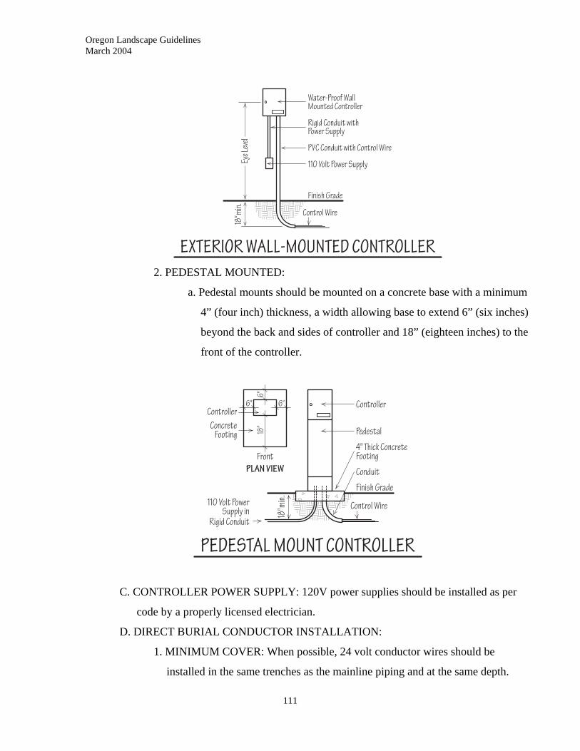
Oregon Landscape Guidelines March 2004
2. PEDESTAL MOUNTED:
a. Pedestal mounts should be mounted on a concrete base with a minimum
4” (four inch) thickness, a width allowing base to extend 6” (six inches)
beyond the back and sides of controller and 18” (eighteen inches) to the
front of the controller.
C. CONTROLLER POWER SUPPLY: 120V power supplies should be installed as per
code by a properly licensed electrician.
D. DIRECT BURIAL CONDUCTOR INSTALLATION:
1. MINIMUM COVER: When possible, 24 volt conductor wires should be
installed in the same trenches as the mainline piping and at the same depth.
111
Oregon Landscape Guidelines March 2004
112
Conductors installed separate from piping should be buried a minimum of 12”
(twelve inches) or 6” (six inches) if installed in conduit.
2. BURIAL UNDER PAVING:
a. When run under paving, conductors should be placed in a sleeve or
conduit. Changes of direction in sleeve/conduit should be made with
sweep ells.
b. 24 volt irrigation conductors should not be run in conduit carrying
120/240 volt power lines.
3. SPLICES AND TAPS:
a. Splices and taps should only be made in approved splice boxes or valve
boxes that permit inspection and repair.
b. Splices and taps should only be made with approved connectors that are
fully insulated and protected against moisture.
4. SINGLE CONDUCTORS: All conductors on the same control circuit should
be installed in the same trench.
5. CONDUCTOR HANDLING: All conductors should be handled with care to
avoid damage to wire and/or insulation. This includes stretching and/or
mechanical damage. Repairs should be made as per splices and taps.
6. BUNDLING AND EXPANSION COILS: Multiple, single, direct burial
conductors in the same trench should be bundled with electrical tape or other
approved fastener every 15’ (fifteen feet).
7. CABLE IDENTIFICATION: Conductors for the common wire and for each
control valve should be clearly color coded and/or marked.
E. ABOVE GROUND CONDUCTOR INSTALLATION:
1. PROTECTION:
a. Direct burial conductors brought above ground for connection to a low
voltage controller, or to carry 120 volt current, should be installed in
code and/or specified conduit with sweep ells. Conduit for 120 Volt and
higher conductors shall be installed by a properly licensed electrician.
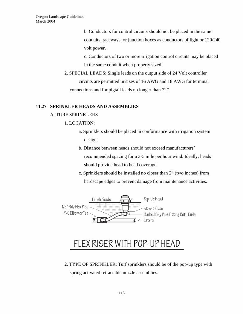
Oregon Landscape Guidelines March 2004
b. Conductors for control circuits should not be placed in the same
conduits, raceways, or junction boxes as conductors of light or 120/240
volt power.
c. Conductors of two or more irrigation control circuits may be placed
in the same conduit when properly sized.
2. SPECIAL LEADS: Single leads on the output side of 24 Volt controller
circuits are permitted in sizes of 16 AWG and 18 AWG for terminal
connections and for pigtail leads no longer than 72”.
11.27 SPRINKLER HEADS AND ASSEMBLIES
A. TURF SPRINKLERS
1. LOCATION:
a. Sprinklers should be placed in conformance with irrigation system
design.
b. Distance between heads should not exceed manufacturers’
recommended spacing for a 3-5 mile per hour wind. Ideally, heads
should provide head to head coverage.
c. Sprinklers should be installed no closer than 2” (two inches) from
hardscape edges to prevent damage from maintenance activities.
2. TYPE OF SPRINKLER: Turf sprinklers should be of the pop-up type with
spring activated retractable nozzle assemblies.
113
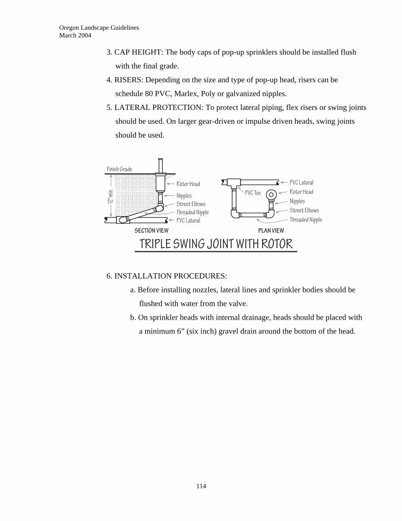
Oregon Landscape Guidelines March 2004
3. CAP HEIGHT: The body caps of pop-up sprinklers should be installed flush
with the final grade.
4. RISERS: Depending on the size and type of pop-up head, risers can be
schedule 80 PVC, Marlex, Poly or galvanized nipples.
5. LATERAL PROTECTION: To protect lateral piping, flex risers or swing joints
should be used. On larger gear-driven or impulse driven heads, swing joints
should be used.
6. INSTALLATION PROCEDURES:
a. Before installing nozzles, lateral lines and sprinkler bodies should be
flushed with water from the valve.
b. On sprinkler heads with internal drainage, heads should be placed with
a minimum 6” (six inch) gravel drain around the bottom of the head.
114
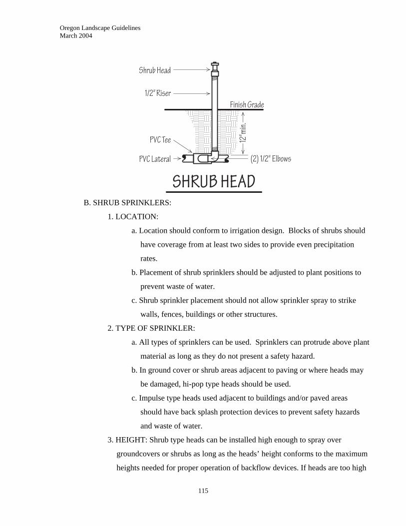
Oregon Landscape Guidelines March 2004
B. SHRUB SPRINKLERS:
1. LOCATION:
a. Location should conform to irrigation design. Blocks of shrubs should
have coverage from at least two sides to provide even precipitation
rates.
b. Placement of shrub sprinklers should be adjusted to plant positions to
prevent waste of water.
c. Shrub sprinkler placement should not allow sprinkler spray to strike
walls, fences, buildings or other structures.
2. TYPE OF SPRINKLER:
a. All types of sprinklers can be used. Sprinklers can protrude above plant
material as long as they do not present a safety hazard.
b. In ground cover or shrub areas adjacent to paving or where heads may
be damaged, hi-pop type heads should be used.
c. Impulse type heads used adjacent to buildings and/or paved areas
should have back splash protection devices to prevent safety hazards
and waste of water.
3. HEIGHT: Shrub type heads can be installed high enough to spray over
groundcovers or shrubs as long as the heads’ height conforms to the maximum
heights needed for proper operation of backflow devices. If heads are too high
115
Oregon Landscape Guidelines March 2004
116
to be practical, or unsightly, the head height should be set to spray under the
branching.
4. RISERS: All heads mounted above grade should have risers of galvanized steel
or schedule 80 PVC to prevent breakage.
5. LATERAL PROTECTION: Heads mounted above grade should use swing
joints to protect lateral pipe. Where physical damage is likely and risers do not
pose a danger, steel rebar and pipe clamps can be used to stake risers.
6. Lateral lines and risers should be flushed with water from valves prior to
nozzle installation.
C. BUBBLER SPRINKLERS:
1. LOCATION: Bubblers should be located to directly place water in the plant
root zone.
2. HEIGHT: Bubblers should be mounted low, 2-3” (two to three inches) above
grade, to prevent washing of soil or mulch surface.
3. RISERS: Riser types and installation should be the same as shrub heads.
4. LATERAL PROTECTION AND INSTALLATION: Same as for shrub heads.
D. SWING JOINTS and FLEX RISERS:
1. USE OF SWING JOINTS: Swing joints should be used to protect all sprinklers
with risers that extend above grade, pop-up sprinklers with large surface area
that are exposed to the weight of maintenance equipment and on quick
coupling valves.
2. MAKE-UP: Swing joints may be double or triple and are used to adjust height
of sprinkler relative to grade.
3. FLEX RISERS: For smaller heads at grade, flex risers may be used for heads
with 1/2” (one half inch) and 3/4” (three quarter inch) threads. Flex risers use
flexible poly tube (“funny pipe”) and poly street ells.
E. ANTI-DRAIN VALVES:
1. PURPOSE: Anti-drain valves are used to prevent low head drainage in the
lateral lines of sprinkler circuits.
2. LOCATION: Anti-drain and/or check valves should be placed in the lateral
line prior to the lowest head or may be an integral part of the sprinkler head.
Oregon Landscape Guidelines March 2004
117
Valves should be checked as to the amount of static pressure elevation gain
that they will hold against.
11.28 BOOSTER PUMPS
A. GENERAL REQUIREMENTS
1. Booster pumps should be installed on solid, level concrete or steel bases with
anti-vibration fasteners.
2. All electrical connections should be made in accordance with code and should
be done by a properly licensed electrician.
3. Booster pump inlets should be under positive pressure.
B. INSTALLATION
1. All installations should include:
a. A low-intake water circuit to shut down pump if water supply is
interrupted.
b. Low-discharge safety circuit to shut down pump if pressure drops
below a preset level do to line break.
c. High-discharge safety circuit to shut down pump if discharge pressure
exceeds a preset level.
d. If needed for elevation, a check valve to prevent backsiphonage.
e. A reduced pressure backflow preventer to protect potable water.
2. Outdoor installations should have waterproof electrical motors or be placed in
weatherproof enclosures.
11.29 DRIP/LOW VOLUME IRRIGATION
A. DESCRIPTION: Low volume irrigation designed to water specific areas with set flow
rates controlled by emission devices such as emitters, micro-sprays and laser tubes.
B. APPLICATION: Low volume irrigation systems can be used in place of any
conventional irrigation system when water filtering and system maintenance will
allow.
C. PRESSURE RANGES
1. LOW PRESSURE: 3-25 (three to twenty five) PSI
Oregon Landscape Guidelines March 2004
118
3. TUBING:
a. Pressure regulation and/or flow restriction devices required.
b. Filtration of 150 (one hundred fifty) mesh or better normally required.
2. MEDIUM PRESSURE: 15-45 (fifteen to forty five) PSI
a. Pressure regulation and/or flow restriction devices required.
b. Filtration of 150 (one hundred fifty) mesh or better normally required.
3. HIGH PRESSURE: 30-90 (thirty to ninety) PSI
a. Filtration of 80 (eighty) mesh normally required.
b. Pressure regulation is required over 90 (ninety) PSI
D. SYSTEM PLANNING
1. Systems should be planned with ease of maintenance and future adjustment in
mind.
2. Specific water requirement for each plant and/or block of plants/turf should be
calculated.
3. System should be laid out in conjunction with planting plan and/or existing
plantings to accurately deliver water.
4. Tubing should be hydraulically sized to deliver proper water flow and pressure
to each planting area and to allow for addition of emission devices as
plants/plantings grow.
E. INSTALLATION
1. VALVES: Install as per section 11.26: VALVES AND VALVE BOXES.
2. FILTRATION DEVICES: Should be installed in the location and manner
specified by manufacturer.
a. Poly delivery and emission tubing should be installed in protected areas
when feasible.
b. Tubing should be easy to locate to prevent damage when beds are
cultivated, mulched, etc. It is recommended that supply tubing be run
around perimeters of areas to be watered.
c. Tubing run overhead for specialty situations should allow an extra 6”
(six inches) of length per 100’ (one hundred feet) of run to allow for
expansion and contraction.
Oregon Landscape Guidelines March 2004
119
4. FITTINGS: All fittings should be installed as per manufacturers’
specifications.
5. EMISSION DEVICES
a. Unless approved for underground applications, all devices should be
placed above ground.
b. All above grade devices should have stakes, clips or other devices to
hold them in place.
11.30 WINTERIZATION
A. DESCRIPTION: Winterization of irrigation systems should be performed whenever
and wherever cold winter conditions pose a risk of freeze damage to components.
Methods should be selected according to the amount of risk.
B. SLOPE TO DRAIN METHOD:
1. All piping should be installed with a minimum of 1% (one percent) slope to
drain and no low spots.
2. Trenching should be run to minimize the number of low spots.
3. Drain valves and gravel sumps should be installed at predetermined, accessible
low spots in the piping.
4. Drain devices should be manually operated on continuous pressure pipe and
can be automatic opening on non-pressure lateral lines.
5. Manual drain valves should be of the globe type and installed as per section
11.26 VALVES AND VALVE BOXES.
6. All drain valves should drain to daylight or to a gravel filled sump capable of
draining all the water held in the lines above the drain. The sump should have
enough depth so that when finished draining, the water level in the sump is 6”
(six inches) below the level of the valve.
7. Automatic drain valves should be installed as per manufacturer specifications
and should have a minimum activating pressure of 3 (three) PSI.
8. There should be a minimum of one drain valve for each circuit or zone.
C. AIR EVACUATION METHOD
1. Method allows the introduction of compressed air to blow out the water.
Oregon Landscape Guidelines March 2004
120
2. NEEDED EQUIPMENT
a. An isolation valve the size of the mainline should be installed in the
mainline at a point where the pipe is still at a frost free depth (usually just after
the point of connection).
b. A tee should be installed in the main line downstream of the gate valve
with the tee horizontal.
c. A quick-coupler valve should be provided for blow-out.
d. A quick-coupler key with a hose swivel and air compressor hose
connector allows connection to a compressor for “blow out”
3. BLOW OUT PROCEDURES
a. Turn a valve on at the controller or manually open it.
b. Turn the water off at the point-of-connection. Verify there is only one
water source.
c. Connect air compressor to system via quick-coupler with all control
valves closed. Minimum compressor size 65 (sixty-five) CFM or
adequate size for larger systems.
d. Start compressor. Do not run above 60 psi on small and medium size
residential systems.
e. Run compressor on zone 1 until heads are just misting. Repeat
procedure for all zones.
f. Winterize the DCVA. Do not run more than 20 psi. Wrap PVB/AVB
with insulation wrapped with plastic to protect from weather.
g. Prepare controller for winter.
4. PHYSICAL PROTECTION
a. All above ground equipment that may retain water should be insulated
or removed for the winter. When removed, piping should be capped or
sealed to prevent debris entry.
b. All above-ground equipment exposed to potential physical damage
from winter operations or activities should be removed and piping
sealed.

Oregon Landscape Guidelines March 2004
121
11:31 AS-BUILT DRAWINGS
A. All irrigation systems should have as-built drawings or a written description
identifying the point-of-connection, isolation valve (s), backflow assembly, control
valves, zone locations and controller. Other devices, such as moisture sensors, should
also be identified.
Oregon Landscape Guidelines March 2004
122
12.0 PLANTING
____________________________________________________________
12.01 DESCRIPTION
Planting includes all phases in the installation of trees, shrubs, groundcovers, turf,
annuals and perennials, and/or plants for interior landscapes.
12.02 WORK INCLUDED
This section includes soil preparation, digging, plant selection and installation, staking
and/or guying, mulching, and watering.
12.03 QUALITY ASSURANCE
All plants and/or seeds should be inspected and properly stored to assure optimum health
at planting time. Soils should be analyzed for nutrient and water characteristics prior to
planting. Planting should be carried out as per this standard and as specified by code or
specification.
12.04 SUBMITTALS
Samples of materials including, but not limited to, plants, seed, staking materials,
fertilizers and soil amendments may be required. Contractor should provide samples
when called for by code, specifications or client’s representative.
12.05 SITE CONDITIONS
A. EXISTING CONDITIONS: Rough grading, finish grading, underground utilities,
irrigation piping and site improvements should be completed prior to plantings with
the exception of larger trees and plants which should be placed after rough grading.
Drip irrigation is usually installed after planting also.
B. ENVIRONMENTAL CONDITIONS: When plantings have to take place in wet or
muddy soils or in times of high temperatures, steps should be taken to minimize
compaction in the planting areas and to assure adequate moisture levels for plant
survival. Planting should not take place in freezing weather or in frozen ground.
Oregon Landscape Guidelines March 2004
123
12.06 SCHEDULING
Planting operations should be scheduled to allow the shortest possible time between plant
delivery to job sites and actual planting.
12.07 SUBSTITUTIONS
All substitutions of plants and/or materials specified should be approved in writing unless
original contract permits contractor substitutions in which case, substitutions should have
similar characteristics to the original selections.
12.08 WARRANTY
Contractor should be responsible for the quality of all materials used and workmanship
for a period of 6 months of growing season following the completion and final inspection
of work if proper maintenance is provided as per the Maintenance Section.
12.09 SOIL AND/OR GROWING MEDIA
A. GROWING MEDIA: Should be fertile, friable and of a quality that will promote plant
health.
B. SOIL: Soil should be reasonably free of rocks, debris and noxious weeds. Soils
should be tested and, if it is subsoil or of poor quality, sufficient topsoil or
amendments should be brought in to assure plant health.
C. IMPORTED SOIL: Should be free of diseases, weeds, pests and debris. If topsoil is
brought in that has different textural qualities it should be handled as per section 5.06
FILL SOIL MATERIAL and section 5.07 TOPSOIL.
12.10 SOIL AMENDMENTS
A. MATERIALS: Soil amendments should be approved compost, wood or bark products,
sand, pumice, cinders and/or other dry organic matter.
B. REQUIREMENTS: Amendments should be free of diseases, pests, weeds, and or
chemicals including herbicides. Those amendments whose carbon to nitrogen ratio
exceeds 20:1 (twenty to one), should have supplemental nitrogen added prior to
plantings.
Oregon Landscape Guidelines March 2004
124
C. CODE AND SPECIFICATION COMPLIANCE: All amendments used should
comply with any applicable codes and/or regulations.
D. APPLICATION: All amendments should be applied as indicated by soil tests and in a
manner that is environmentally safe.
12.11 FERTILIZERS
A. Fertilizers may be organic or synthetic and can be in pellet, tabular, granular or liquid
form. All fertilizers used must have labeling that conforms to environmental and
safety requirements set forth by state and national regulations.
B. APPLICATION: All fertilizers should be applied as per label instructions, as indicated
by soil tests and in a manner that is environmentally safe.
12.12 PLANT MATERIALS
A. QUALITY AND SIZE:
1. Quality and size of plants should conform to the American Association of
Nurserymen Standards for Nursery Stock.
2. The American Association of Nurserymen’s guides to on-site plant selection
should be used as a guideline for inspecting plants delivered to the job.
a. Container grown plants should retain a minimum of 75% (seventy five
percent) of their rootball mass when planted.
b. When lifted by the trunk, container plants should rise no more than 1”
(one inch) before the rootball begins to rise.
c. When planted without support, trees should not lean more than 30
(thirty) degrees from the vertical when measured 4” (four inches) above
the rootball.
3. All specified plants should be reasonably uniform in size, texture and color for
the species, in relatively good health with no damage or diseases.
4. Groundcover plants: All rooted cuttings should be healthy vegetative material
with well established roots at one or more nodes. Container grown stock
should have viable roots through at least 50% (fifty percent) of the medium.
Oregon Landscape Guidelines March 2004
125
B. PLANT HEALTH:
1. All plants used should comply with Federal and State laws and quarantines that
affect their use.
2. Plants shipped from out of state by the landscape contractor should have all
required ODA inspection certificates delivered with them.
12.13 TURF SOD AND SEED
A. SOD: All sod should be free of diseases and weeds; cut at a uniform thickness and
should have root structure well enough established to prevent tearing when handled.
B. TYPE: Sod should be of a type specified and/or selected for the geographical and
localized site to be planted.
C. STORAGE: When stored for more than 24 hours, sod should retain uniform color and
good health for installation
D. SEED: All seed should be selected for the particular application and should be labeled
in accordance with the Association of Official Seed Certification Agencies. Seed
should be planted within one year of its harvest.
12.14 OTHER MATERIALS
A. TREE STAKES: Stakes should be of sufficient size and strength to support trees
against windthrow and vandalism as needed to allow good root establishment and
trunk protection.
B. TREE TIES: Tree ties should be of a durable, non-abrasive material and should
support the tree while allowing tree movement in the wind.
C. CHEMICAL WEED CONTROLS: When used, herbicides should conform to national,
state and local codes; should only be used as per label instructions; and should be
used in a safe and environmentally protective manner. Applications should only be
made by individuals properly licensed by the ODA.
D. MULCH: Suitable materials include compost, bark dust, wood chips and gravel.
Selection should conform to codes and specifications. All materials should be free of
disease and insects.
Oregon Landscape Guidelines March 2004
126
12.15 PLANTING
A. SOIL PREPARATION:
1. Preparation of planting areas should consist of rough grading, cultivation where
needed, incorporation of soil amendments and fertilization (if called for),
finished grading and mulching (if called for).
2. Planting beds that are cultivated beds, and areas for turfgrass should be
cultivated to a minimum depth of 6” (six inches) to break up compaction and
reduce the chance of transition layers. Over tilling, causing the breakdown of
soil structure should be avoided. If amendments are to be worked into entire
bed, it should be done at this stage.
3. After cultivation, and incorporation of amendments when called for, beds
should be finish graded. Finish grades should be set 1” (one inch) minimum
below hardscape surfaces to allow drainage into planting areas.
4. SLOPES: MINIMUM AND MAXIMUM FOR LANDSCAPE FINISH
GRADES:
a. Adjacent to site structures (away) ---- 2-10% (two to ten percent)
b. Lawn/turf areas ---------------------2-20% (two to twenty percent)
c. Slopes with plants-------------------- 3-50% (three to fifty percent)
d. Slopes with stable groundcover-- 3-100% (three to one hundred)
5. All planting areas should be free of debris, smooth and free of rocks or clods
over 3/4” (three-quarter inch).
12.16 PLANTING HOLES
A. PREPARATION: Should consist of laying out plant locations, digging holes, and
adding amendments if called for.
B. LOCATIONS: Plants should be located as per plan or specification. Placement should
be modified to avoid existing utilities, and irrigation equipment. Major movement of
plants should be approved by owner or owner’s representative. If the contractor
recognizes problems with ultimate plant size for area specified, contractor should
inform owner or owner’s representative in writing about substituting or moving plant.
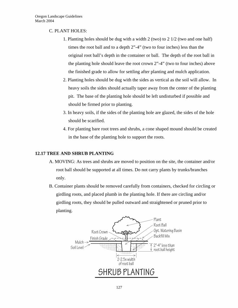
Oregon Landscape Guidelines March 2004
C. PLANT HOLES:
1. Planting holes should be dug with a width 2 (two) to 2 1/2 (two and one half)
times the root ball and to a depth 2”-4” (two to four inches) less than the
original root ball’s depth in the container or ball. The depth of the root ball in
the planting hole should leave the root crown 2”-4” (two to four inches) above
the finished grade to allow for settling after planting and mulch application.
2. Planting holes should be dug with the sides as vertical as the soil will allow. In
heavy soils the sides should actually taper away from the center of the planting
pit. The base of the planting hole should be left undisturbed if possible and
should be firmed prior to planting.
3. In heavy soils, if the sides of the planting hole are glazed, the sides of the hole
should be scarified.
4. For planting bare root trees and shrubs, a cone shaped mound should be created
in the base of the planting hole to support the roots.
12.17 TREE AND SHRUB PLANTING
A. MOVING: As trees and shrubs are moved to position on the site, the container and/or
root ball should be supported at all times. Do not carry plants by trunks/branches
only.
B. Container plants should be removed carefully from containers, checked for circling or
girdling roots, and placed plumb in the planting hole. If there are circling and/or
girdling roots, they should be pulled outward and straightened or pruned prior to
planting.
127
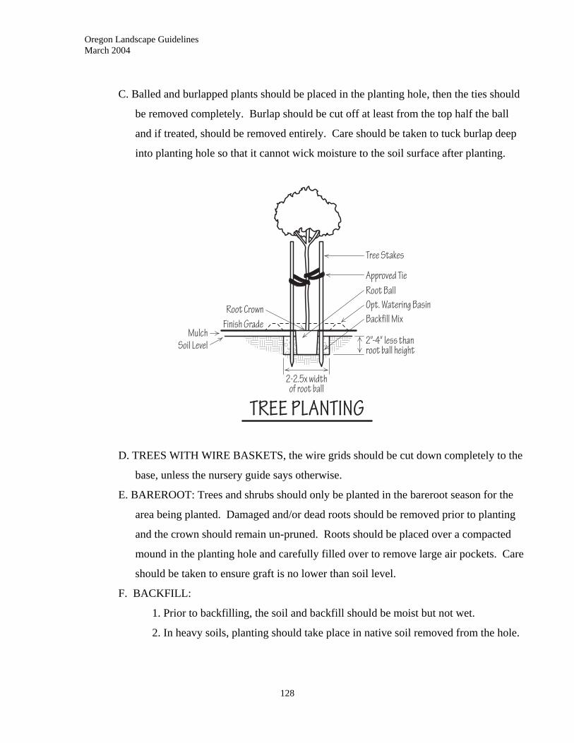
Oregon Landscape Guidelines March 2004
C. Balled and burlapped plants should be placed in the planting hole, then the ties should
be removed completely. Burlap should be cut off at least from the top half the ball
and if treated, should be removed entirely. Care should be taken to tuck burlap deep
into planting hole so that it cannot wick moisture to the soil surface after planting.
D. TREES WITH WIRE BASKETS, the wire grids should be cut down completely to the
base, unless the nursery guide says otherwise.
E. BAREROOT: Trees and shrubs should only be planted in the bareroot season for the
area being planted. Damaged and/or dead roots should be removed prior to planting
and the crown should remain un-pruned. Roots should be placed over a compacted
mound in the planting hole and carefully filled over to remove large air pockets. Care
should be taken to ensure graft is no lower than soil level.
F. BACKFILL:
1. Prior to backfilling, the soil and backfill should be moist but not wet.
2. In heavy soils, planting should take place in native soil removed from the hole.
128
Oregon Landscape Guidelines March 2004
129
3. In light soils the backfill should be mixed with soil amendments as specified.
Amendments with high carbon to nitrogen ratios should not be used when
planting new plants.
4. Planting holes should be backfilled in layers to firmly surround the plant’s
roots.
5. Large air pockets should all be removed. If planting holes are settled using
water, care should be taken to avoid over compaction and subsequent loss of
structure.
G. WATERING: Plants should be thoroughly watered in after backfill. In light soils or
situations where water will not stay in plant root zone area, water basins should be
created to facilitate watering until the plants are established.
H. FINISH GRADING: All planting areas should be graded to a smooth finish and
mulched to a 2-4” (two to four inch) depth as specified to complete the work.
I. PRUNING: At planting time, pruning should be kept to a minimum. Damaged,
diseased and/or dead material should be removed.
12.18 GROUNDCOVER, ANNUAL AND PERENNIAL PLANTS
For groundcover, perennial and/or annual plantings, entire beds should be prepared and
amended as specified prior to planting. Plants should be planted at the spacing and
pattern specified and then watered in.
12.19 TREE STAKING AND GUYING
A. STAKING:
1. Trees should be staked only when necessary to prevent windthrow and/or to
protect them from vandalism.
2. When used, staking should be low on the tree and should allow trunk
movement. Stakes should be driven into firm, undisturbed, soil in a position
parallel to the prevailing wind direction.
3. Trees should be tied to stakes with approved non abrasive material such as
chain-lock or arbortie (Copyright) as per manufacturers’ specifications.
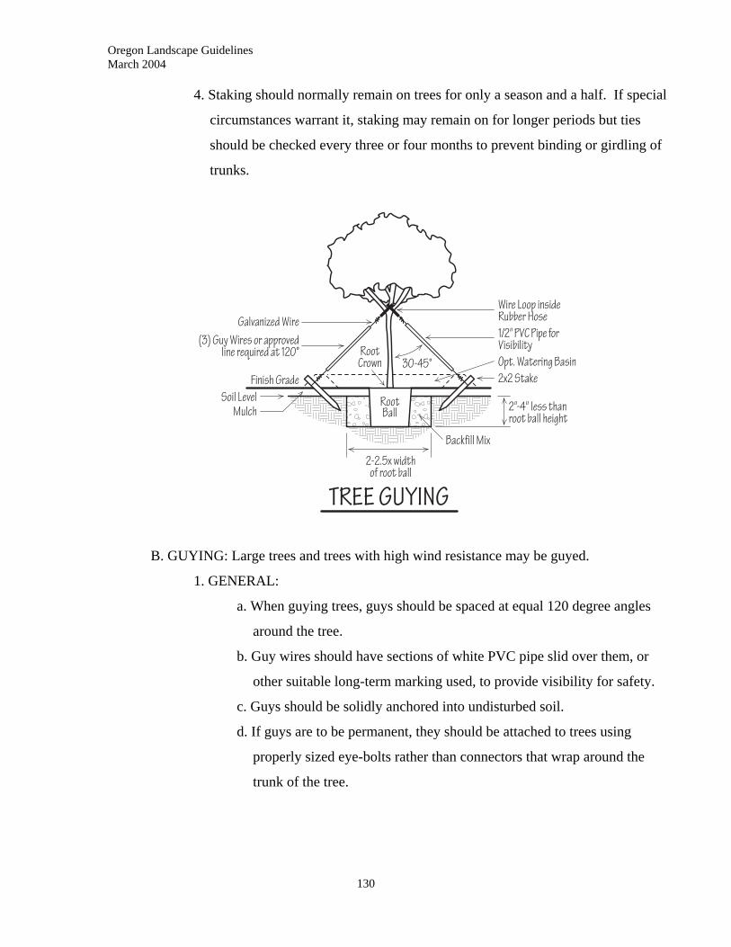
Oregon Landscape Guidelines March 2004
4. Staking should normally remain on trees for only a season and a half. If special
circumstances warrant it, staking may remain on for longer periods but ties
should be checked every three or four months to prevent binding or girdling of
trunks.
B. GUYING: Large trees and trees with high wind resistance may be guyed.
1. GENERAL:
a. When guying trees, guys should be spaced at equal 120 degree angles
around the tree.
b. Guy wires should have sections of white PVC pipe slid over them, or
other suitable long-term marking used, to provide visibility for safety.
c. Guys should be solidly anchored into undisturbed soil.
d. If guys are to be permanent, they should be attached to trees using
properly sized eye-bolts rather than connectors that wrap around the
trunk of the tree.
130
Oregon Landscape Guidelines March 2004
131
2. METHODS of ANCHORING:
a. “Duck-bill Anchors” may be used. Duck bills should be attached to
proper tree staking fasteners. Turnbuckles should be used for
tightening guys.
b. Stakes, driven in at a 60 (sixty) degree angle sloped away from the tree
may be used. Stakes should be clearly flagged or painted to avoid trip
hazards.
c. DEADMEN: made of concrete or pressure treated wood, deadmen
should be buried at right angles to the tree. Size of deadmen needs to
be developed for each specific application. Removal of deadmen
should be considered before use as damage may occur to root system
and they may interfere with other landscape operations or equipment.
12.20 SODDING and SEEDING TURFGRASS
A. SOIL PREPARATION:
1. Soil should be prepared as in 12.15 PLANTING, section A. SOIL
PREPARATION.
2. Finish grade should be a minimum of 1” (one inch) below surface of adjoining
hardscapes.
3. Prior to seeding or sodding, soil should be evenly moistened.
4. Fertilization should be based on soil tests and low amounts of soluble nitrogen
should be applied prior to planting.
5. Prior to seeding or sodding, entire area should be rolled with a drum roller to
firmly compact the grade.
B. SODDING:
1. Sod used should be compatible with the microclimate being landscaped.
2. Sod delivered to installation sites should be used within 24 (twenty four) hours,
or special precautions should be taken to avoid drying and/or burning.
3. Sod should be laid in straight rows with the ends of sod strips making close
contact with each other and end joints staggered. Sod should make firm
contact with the soil.
Oregon Landscape Guidelines March 2004
132
4. After sod is laid, and prior to initial watering, it should be rolled.
5. On steep slopes, sod should be laid perpendicular to the slope and should be
fastened with turf staples.
6. Sod and soil bed should be kept moist throughout the planting operation. Upon
completion of planting, sod should be thoroughly watered and placed under
irrigation or watered regularly.
7. First mowing of sod should take place as soon as sod has rooted in. No more
than 1/3 (one third) of leaf height should be removed at any one mowing.
C. SEEDING:
1. Seed selected should be compatible with the microclimate of the site being
planted and should be certified by the Association of Official Seed
Certification Agencies.
2. The choice of seed type, seeding rate, blends and/or mixes, percent viability
and purity should be made according to specifications and/or grower
recommendations.
3. Soil should be rolled prior to seeding and the top ¼” (one quarter inch) of
surface lightly loosened.
4. One half of seed should be sown in one direction and one half in opposite
direction.
5. After seed has been sown, it should be covered with a raking method (hand
raked, tiller rake or steel chain mat) so that it is covered with ¼ - 1/3” (one
quarter to one third inch) of soil or mulch unless otherwise specified by
supplier.
6. Seed bed should be kept evenly moist until grass is well established.
7. Mowing should begin when grass has reached a height 50% (fifty percent)
taller than the height it will be regularly mowed (varies according to turf type).
Oregon Landscape Guidelines March 2004
133
13.0 LANDSCAPE LIGHTING
____________________________________________________________
13.01 DESCRIPTON
A. Landscape lighting includes the placement and installation of outdoor lighting systems
for the following:
1. SAFETY on circulation paths, stairs, patios and decks.
2. SECURITY with general area lighting.
3. MOOD LIGHTING including variable use area lighting, depth lighting to
enhance landscape areas, and effect lighting.
4. FOCAL OR SPOT LIGHTING to enhance specific areas or features in
landscape.
13.02 WORK INCLUDED
This section includes only the selection and installation of “low voltage” landscape
systems as defined in NEC (National Electrical Code) Article 411.
13.03 CONTRACTOR RESPONSIBILITY
A. Landscape Contractor is licensed to install “low voltage” systems only. All 120 and
240 volt electrical systems must be installed by a properly licensed electrician.
B. All work performed must comply with the National Electrical Code and any other
applicable codes.
C. Contractor will be responsible for ensuring any required permits are obtained prior to
commencement of work.
13.04 WARRANTY
A. All manufacturers’ warranties and operational directions for lighting systems should
be turned over to client upon completion of work.
B. Contractor should educate owner as to proper operation, maintenance and replacement
of lamps.
C. Contractor’s warranty, if any, should be specified in written contract.
Oregon Landscape Guidelines March 2004
134
13.05 MATERIALS
A. GENERAL: All cables, wire, transformers and fixtures must meet all applicable code
requirements and meet UL (Underwriters Laboratory) standards. All products must
conform to NEC Article 411.
B. GROUND FAULT INTERRUPTERS: All circuits for outdoor lighting must be
protected with approved ground fault interrupter circuit breakers.
C. CONDUIT: All wiring and cable placed in conduit for mechanical and/or code
compliance should be placed in rigid galvanized conduit or Sch. 40 PVC gray conduit
as specified by code or written specifications.
D. LOW VOLTAGE CABLE: Cable should be type UF (Underground Feeder), stranded,
properly sized AWG (American Wire Gauge) minimum, of direct burial quality and
covered with insulation treated to inhibit actions of oil, water, Salt, UV radiation and
to repel rodents.
E. LOW VOLTAGE TRANSFORMERS:
1. Transformers should be manufactured specifically for outdoor low voltage
lighting and may be single tap or multi-tap types.
2. Transformers should be sized to supply even voltage to all fixtures on a circuit.
Voltage for halogen lamps should not be lower than 10.8 volts nor greater than
12.2 volts.
3. Exterior mounted transformers must be weather tight (NEMA 3R).
F. WIRE SPLICES/CONNECTORS: Connectors should be water tight and make positive
contact. If wire nuts are used, they should be properly sized for the wire used and
should have an approved watertight connection.
G. CONTROLS AND SWITCHES
1. Controls, either solid state or photocell, should be approved for the application
and conform to system requirements.
2. All switches used should conform to all applicable electrical codes.
H. FIXTURES: All fixtures used should be weatherproof. Fixtures should match the
intended design use and/or specification. All fixtures should be supplied with the
proper lamps.
Oregon Landscape Guidelines March 2004
135
13.06 INSTALLATION
A. SUPPLY WIRING AND PROTECTION
1. Installation of 120 volt supply wiring and GFI protection should be carried out
by a licensed electrician.
B. GROUND FAULT INTERRUPTERS: Approved GFI circuit breakers or receptacles
should be used to protect all transformers and circuits and should be installed by a
licensed electrician as per code.
C. TRANSFORMERS:
1. Transformer should be sized to supply uniform voltage to each lamp on a
circuit:
a. Determine size by total watts needed.
b. Amperage and volts should be compatible with cable and lamps used.
c. Transformer should be installed in an easily accessible location and to
manufacturer’s recommendations
D. LOW VOLTAGE CABLE:
1. Cable should be sized appropriately.
2. If directly buried, cable should be type UF.
3. Cable should be run loosely to accommodate the placement of fixtures.
4. Cable placed in trees should be run up the side away from normal viewing and
should be fastened securely.
5. The length of cable runs between fixtures should be limited to a distance that
will allow proper operating voltage to each lamp as per manufacturer’s
recommendations.
6. Cable from transformers to fixtures should be run in a method that limits the
voltage difference to no more than 1-volt between lamps
7. Where possible, cable should be fastened directly to connectors on fixtures. If
not possible, connections to pigtails should be secure and properly protected to
avoid excessive voltage loss and possible overheating.
E. FIXTURES:
1. All fixtures should be installed as per code and manufacturer specifications.

Oregon Landscape Guidelines March 2004
136
2. Fixtures should be placed so as to not shine directly into landscape users’ eyes.
This protection is usually achieved by the placement of thefixtures, the use of
baffles, louvers and special lenses, or a combination of any of these.

Oregon Landscape Guidelines March 2004
137
14.0 WATER FEATURES
____________________________________________________________
14.01 DESCRIPTION
Ornamental water features are placed into the landscape to provide visual interest, set
moods, and to support plants and wildlife. They can be formal or informal and can be
from the size of small butterfly pools to large ponds and streams. This section does not
include natural bodies of water or bio-swales.
14.02 WORK INCLUDED
This section includes the ground preparation, construction, drainage and maintenance of
water features in the landscape.
14.03 QUALITY ASSURANCE
All materials and workmanship should be done in accordance with manufacturer’s
specifications and should meet all applicable code and regulation requirements. All work
should be performed as per written contract.
14.04 CONTRACTOR RESPONSIBILITY
A. Contractor should be properly licensed with the landscape contractors’ board.
B. Contractor is responsible for all needed permits and inspections.
14.05 WARRANTY
Upon completion of work, all equipment warranties should be delivered to the client by
the contractor. Guaranty of workmanship, if any, should be stated in written contract.
14.06 MATERIALS
A. LINERS AND CONTAINERS
1. CONCRETE/MORTAR: Refer to section 8.08 MATERIALS –CONCRETE
CONSTRUCTION
2. LINERS: Liners should be flexible, UV resistant, and should have a stated
warranty period. “EDPM” rubber liners are recommended.
Oregon Landscape Guidelines March 2004
138
3. Molded fiberglass containers: Fiberglass containers should be of sufficient
thickness to resist mechanical damage and should be UV resistant.
4. OTHER: Pots, vases and other containers should be weatherproof and
waterproof. If fish or other aquatic life are planned for, vessels should be
checked to be sure they are non-toxic.
B. PUMPS: All pumping systems should be UL approved and should be capable of
providing the flow and lift called for in design specifications. All pumps should be
sealed to prevent contamination of water supply.
C. FILTERS: When used, filters should be capable of treating the volume of water
utilized by the particular feature and matched to the pumping system.
D. PIPING: Piping may be rigid PVC, flexible PVC or Polyethelene (PE) pipe.
14.07 INSTALLATION
A. GENERAL: All pond and stream installations should comply with the following:
1. SECURITY: Depth of water features should be checked against all applicable
codes to see if security fencing and locked areas will be necessary.
2. WATER SUPPLY: Pools and streams supplied directly from potable water
supplies should be protected with backflow devices as per plumbing code.
Installation of such devices should only be carried out by contractors licensed
for Irrigation and LBDI or by properly licensed plumbers.
3. OVERFLOW AND DRAINAGE: Overflow and drainage from ponds should
be captured on-site in sumps or bio-swales. Water features should not be
drained into storm water facilities. In all features, liners should extend a
minimum of 6” (six inches) above water level to prevent overflow and should
rise 6” (six inches) minimum above surrounding grade to prevent rain and/or
irrigation run-off from overflowing feature.
4. GROUNDWATER: All in-ground features should have the groundwater
drainage checked prior to installation. If groundwater is a concern, subsurface
drains should be laid to prevent hydraulic bubbles in liners or washing of base
under concrete.
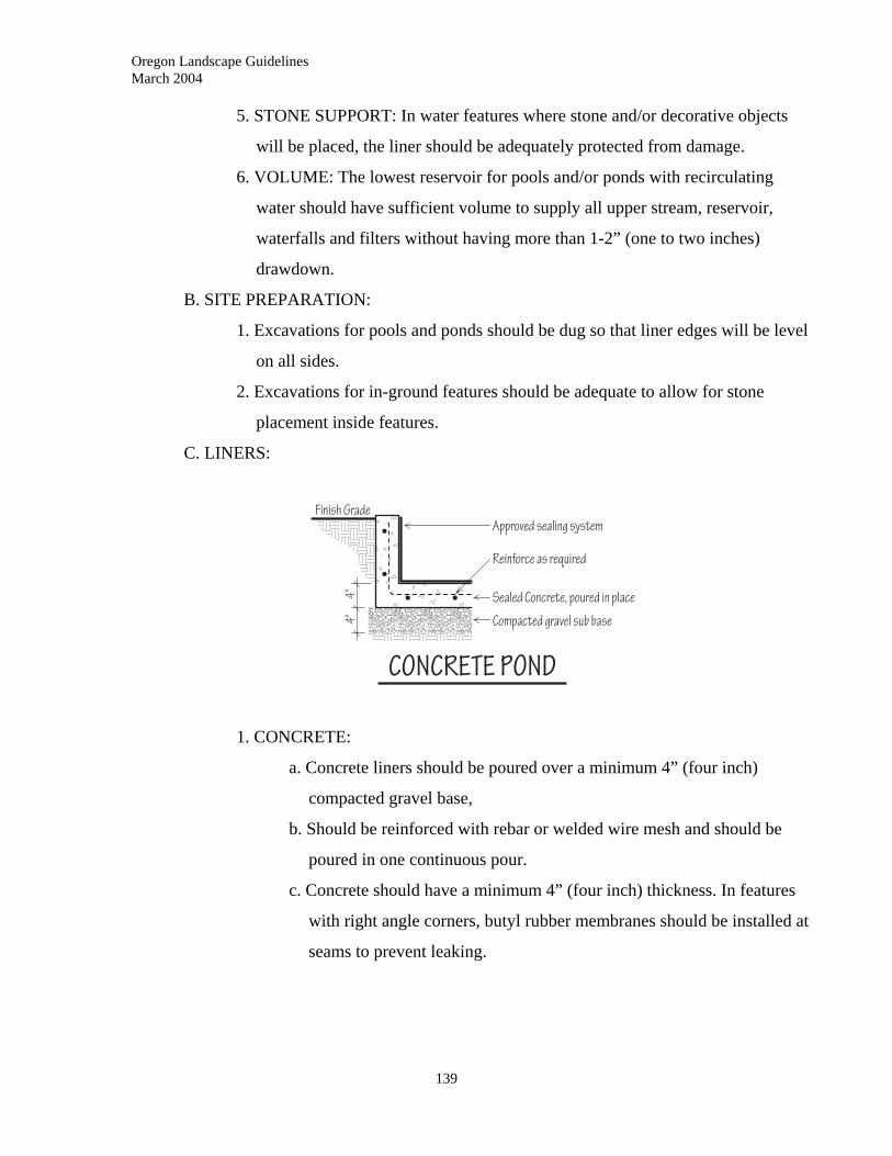
Oregon Landscape Guidelines March 2004
5. STONE SUPPORT: In water features where stone and/or decorative objects
will be placed, the liner should be adequately protected from damage.
6. VOLUME: The lowest reservoir for pools and/or ponds with recirculating
water should have sufficient volume to supply all upper stream, reservoir,
waterfalls and filters without having more than 1-2” (one to two inches)
drawdown.
B. SITE PREPARATION:
1. Excavations for pools and ponds should be dug so that liner edges will be level
on all sides.
2. Excavations for in-ground features should be adequate to allow for stone
placement inside features.
C. LINERS:
1. CONCRETE:
a. Concrete liners should be poured over a minimum 4” (four inch)
compacted gravel base,
b. Should be reinforced with rebar or welded wire mesh and should be
poured in one continuous pour.
c. Concrete should have a minimum 4” (four inch) thickness. In features
with right angle corners, butyl rubber membranes should be installed at
seams to prevent leaking.
139
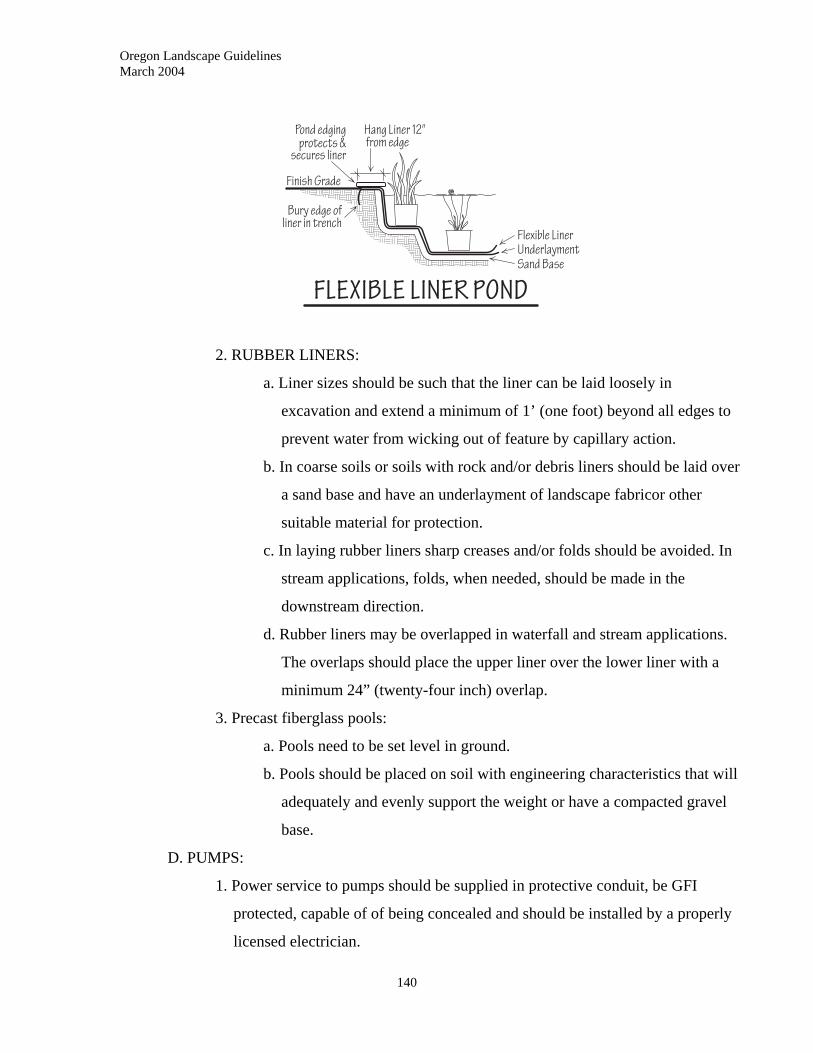
Oregon Landscape Guidelines March 2004
2. RUBBER LINERS:
a. Liner sizes should be such that the liner can be laid loosely in
excavation and extend a minimum of 1’ (one foot) beyond all edges to
prevent water from wicking out of feature by capillary action.
b. In coarse soils or soils with rock and/or debris liners should be laid over
a sand base and have an underlayment of landscape fabricor other
suitable material for protection.
c. In laying rubber liners sharp creases and/or folds should be avoided. In
stream applications, folds, when needed, should be made in the
downstream direction.
d. Rubber liners may be overlapped in waterfall and stream applications.
The overlaps should place the upper liner over the lower liner with a
minimum 24” (twenty-four inch) overlap.
3. Precast fiberglass pools:
a. Pools need to be set level in ground.
b. Pools should be placed on soil with engineering characteristics that will
adequately and evenly support the weight or have a compacted gravel
base.
D. PUMPS:
1. Power service to pumps should be supplied in protective conduit, be GFI
protected, capable of of being concealed and should be installed by a properly
licensed electrician.
140
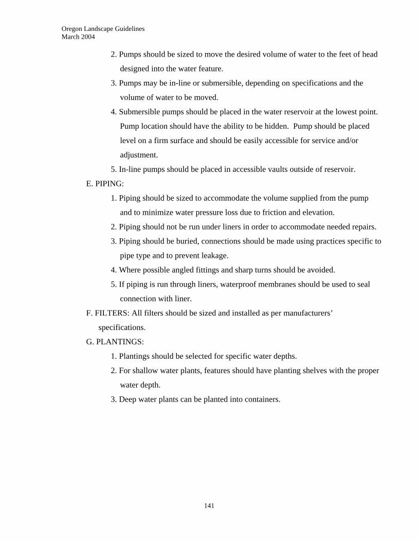
Oregon Landscape Guidelines March 2004
141
2. Pumps should be sized to move the desired volume of water to the feet of head
designed into the water feature.
3. Pumps may be in-line or submersible, depending on specifications and the
volume of water to be moved.
4. Submersible pumps should be placed in the water reservoir at the lowest point.
Pump location should have the ability to be hidden. Pump should be placed
level on a firm surface and should be easily accessible for service and/or
adjustment.
5. In-line pumps should be placed in accessible vaults outside of reservoir.
E. PIPING:
1. Piping should be sized to accommodate the volume supplied from the pump
and to minimize water pressure loss due to friction and elevation.
2. Piping should not be run under liners in order to accommodate needed repairs.
3. Piping should be buried, connections should be made using practices specific to
pipe type and to prevent leakage.
4. Where possible angled fittings and sharp turns should be avoided.
5. If piping is run through liners, waterproof membranes should be used to seal
connection with liner.
F. FILTERS: All filters should be sized and installed as per manufacturers’
specifications.
G. PLANTINGS:
1. Plantings should be selected for specific water depths.
2. For shallow water plants, features should have planting shelves with the proper
water depth.
3. Deep water plants can be planted into containers.
Oregon Landscape Guidelines March 2004
H. WATERFALLS AND STREAMS:
1. Water supply should be designed to work with the depth and width of waterfall
features.
2. Waterfalls may be built in place or precast. In either case, stone or other
waterfall material should be mortared into place to avoid water loss behind
falls.
3. Waterfalls and sections of streams should have adequate reservoir volume
directly above each section.
4. The depth of reservoir at each falls or stream section should be adequate to
avoid loss of water due to splash over.
I. STONE:
1. Stone should be placed after liner is complete and before pumping systems are
placed. Stone used to conceal pumps, piping or power cords should not be
mortared.
2. If sharp angular stone is used, additional liner protection should be installed.
14.08 MAINTENANCE
A. ALGAE PREVENTION:
1. If algae prevention is desired, methods include adequate and properly chosen
planting, algaecides and filtration systems. Use of algaecide should conform to
all applicable regulations.
142
Oregon Landscape Guidelines March 2004
143
2. Methods used must be adjusted to volume of water treated. Pool and features
should be regularly topped off to keep water at optimum level.
B. WINTERIZATION: In areas with freezing winters, features without adequate depth to
protect pumps should be designed to be drained and pumps removed for winter. In
situations where pumps run through freezing weather, care should be taken not to
cause flooding and loss of water to pumps through ice build-up.
C. CLEANING:
1. Pump filters should be checked on a regular basis.
2. Features should be drained and surfaces cleaned as needed. If systems and
water are in balance, cleaning should not be performed.
14.09 ADDITIONS
A. No additions should be made to existing water features without first calculating the
capacity of the existing pumping and filtering systems.
Oregon Landscape Guidelines March 2004
144
15.0 LANDSCAPE MAINTENANCE
____________________________________________________________
15.01 DESCRIPTION
The landscape contractor might maintain the landscape plantings and the landscape area
for a specified a period of time, usually the first year after planting or until landscape
plantings are established; or might perform continuing maintenance on the site. The
intent of the maintenance should be to preserve the health of the plants, the overall
appearance of the site and the intended design concept. This section is not intended to
address ongoing maintenance after the first year.
15.02 WORK INCLUDED
This section includes all work performed to maintain a landscape site up to one year after
initial installation including, but not limited to, site inspection; hardscape cleaning;
mowing, fertilization, pruning, and training of plant material, weed, disease and insect
suppression; irrigation scheduling; tree staking removal; plant replacement; mulching;
and general site clean-up.
15.03 QUALITY ASSURANCE
A. COMPLIANCE: All work must comply with client and written specifications and/or
codes as set forth in contract or must be performed at the minimum standard as
indicated.
B. LICENSING: Businesses performing only the maintenance of the landscape do not
have to be licensed landscape contractors. If performing any chemical applications,
they must be properly licensed by the Oregon Department of Agriculture for the
proper pesticide certification. Contractors should limit pruning to no more than 12’
(twelve feet) above ground. Larger trees and pruning heights should be referred to a
licensed arborist.
Oregon Landscape Guidelines March 2004
145
15.04 SITE CONDITIONS
A. SITE INSPECTIONS:
1. Contractor or persons responsible for maintenance should perform a thorough
site inspection prior to the commencement of work. Each site should be
inspected at a one month minimum interval during the growing season.
2. All maintenance requirements for the site should be listed and the maintenance
service provider should be familiar with all plant material including growth
habits and growing requirements
3. Maintenance provider should inform client, or client’s representative, of work
required including scheduling, materials and fees and should enter into contract
for such.
B. ENVIRONMENTAL CONDITIONS
1. The maintenance contractor should take note of any environmental conditions
such as wetlands, existing waterways, drainage patterns, heat sinks, noxious
weeds or quarantined plants, and pest infestations. The client and/or client’s
representative should be notified of such conditions and maintenance practices
should be adjusted accordingly.
15.05 SCHEDULING
A. Maintenance services should be scheduled as per contract on an as-needed basis
depending on the time of year, the individual landscape and the services provided.
B. Changes to those services specified by contract should be approved by the contractor,
and the client or client’s representative in writing.
15.06 WARRANTY
A. CONTRACTOR’S RESPONSIBILITY:
1. Maintenance contractor should furnish all supervision, labor, materials and
supplies, and equipment needed to perform the specified work.
2. All plant material should be maintained in a healthy state, irrigation and
drainage systems kept in good working order, and the general site kept clean
and hazard free.
Oregon Landscape Guidelines March 2004
146
B. CONTRACTOR’S LIABILITY: The maintenance contractor should replace any plant
material or hardscapes damaged by the contractor’s action or lack of action.
C. LIMITS TO CONTRACTOR’S LIABILITY: Contractor should not be responsible for
the following unless specifically agreed to in contract and allowed by law:
1. Replacement and or extension of irrigation components due to client request or
normal wear. Without an irrigation contractors’ license, only minor head and
line repairs may be performed.
2. Replacement and/or renovation of any plant material or other materials
damaged by power failure, weather, vandalism, rodents, other pests or any
other causes beyond the contractors’ control.
3. Renovation and thatching of turf.
4. Rotation of annual color.
15.07 EQUIPMENT
Unless agreed to in written contract, maintenance contractor should provide all necessary
equipment to perform the maintenance services. All equipment should have safety
guards in place and should be used for the manufacturers’ intended purpose. Equipment
should be maintained in the proper condition and adjusted to perform the needed work.
15.08 MATERIALS
A. FERTILIZERS: All fertilizers used should have proper labels with a guaranteed
analysis and should be selected to provide nutrients for specific applications.
B. PESTICIDES: All pesticides should be registered with the EPA, approved for use by
the state of Oregon, approved for the specific application, used only as per label
instructions, and applied only by a licensed applicator.
C. GROWTH REGULATOR: Regulators should be used as per specification and label
direction only and should be applied by a licensed applicator only.
Oregon Landscape Guidelines March 2004
147
15.09 TREES AND SHRUBS
A. PRUNING:
1. In general, trees and shrubs should not be pruned in the first season after
planting except for the removal of dead, damaged or diseased wood or for
training as per specifications. All pruning should conform to the design and
maintenance concepts for the site as agreed to by contractor and client or
client’s representative.
2. Pruning should enhance the desired growth characteristics of the plants and
promote strong structural growth, especially in trees. Trees with single central
leaders need little or no pruning. Such trees should never be topped or have the
central leader removed. Trees with multiple leaders should be pruned to
develop strong structural scaffold branches that are 18-24” (eighteen to twenty
four inches) apart and to prevent “V” crotches. In trees, watersprouts and
suckers should be removed. All pruning cuts should be made to conform with
current practices as set forth by the International Society of Arborists and/or
university extension reasearch.
3. Timing of pruning should be selected based on plant need and design concepts:
a. Shearing and training may have to take place multiple times throughout
the year.
b. Trees and shrubs that bloom on new wood should normally be pruned
after flowering.
c. Trees and shrubs that bloom on second year and older wood should
normally be pruned in the winter dormant season.
d. Trees that are prone to “bleeding”, such as birch, should only be pruned
in early winter or mid-summer.
4. When pruning plants that may have fungal or viral diseases, pruning tool
should be disinfected before each cut is made.
5. Plants requiring special training such as espaliers should be pruned beginning
right after planting and continuing on a regular basis depending on growth rate.
6. Unless specified or desired for special growth pattern or rehabilitation, no more
than 30% (thirty percent) of a plant should be removed at any one pruning.
Oregon Landscape Guidelines March 2004
148
7. All pruning debris should be removed from the site and disposed of in a proper
plant debris recycling site.
B. FERTILIZATION:
1. TREES AND SHRUBS: Fertilization of trees and shrubs should be carried out
on an as needed basis for each individual plant.
a. METHODS: Contractor should select fertilization methods that supply
nutrients to the feeder root zone of plants being fertilized while at the
same time, protecting the environment from run-off and groundwater
pollution. Amounts of fertilizer and formulations should be accurately
calculated and applied for each individual application.
b. MATERIALS: It is recommended that unless specified, contractor
should use the least amount of fertilizers possible; should use slow
release type materials or use organic materials.
C. MULCHING: Where mulch was applied as part of the initial installation, a 2’ to 4”
(two inch to four inch) depth should be maintained. Cost for any additional material
which may be needed should be negotiated with the client or client’s representative.
15.10 TURFGRASS
A. MOWING
1. TIMING/FREQUENCY: Turf should be mowed whenever needed during
active growth. Mowing should be avoided when ground is too wet and/or
when frozen. A task schedule negotiated between the contractor and client or
client’s representative will determine mowing frequency.
2. HEIGHT: Cool season turfgrass should be mowed at heights recommended for
each turf type. Mowing turf at the higher recommended ranges will increase
durability and reduce the amount of water and nutrients required to keep turf
healthy. At any cutting, no more than one third of the length of the blade
should be removed.
3. PATTERN: The pattern of mowing should be changed each time the turf is
mowed to prevent compaction and graining of turf.
Oregon Landscape Guidelines March 2004
149
4. CLIPPINGS: Whenever practical, mulching mowers should be used and
clippings left on the lawn. When clippings are removed, they should be
properly composted or deposited in a recycle site.
5. EDGING: Edging should be performed at a minimum two week interval during
the active growing season to limit the spread of turf, maintain clean edges on
paved areas, and to insure clear operation of sprinkler heads. An agreed upon
task schedule will determine the actual frequency of edging.
6. EQUIPMENT: Mower types should be matched with the specified turf height
and use. Mower blades should be kept sharp and balanced.
B. FERTILIZATION:
1. APPLICATION: Fertilization of turf should be based on soil tests and turf
types.
2. TIMING: Fertilization of turf will be determined by contract requirements and
localized environmental factors.
3. RATES: To prevent environmental damage and to promote overall turf health,
the lowest recommended fertilizer rates for a given area should be used. If
needed, soil Ph should be adjusted to fit the turf type used.
4. When possible, slow release and/or organic fertilizers should be used.
5. Fertilizers should be applied as per manufacturer’s specifications and generally
should be watered in after application.
6. Care should be taken in spreading fertilizer to prevent overthrow into areas not
needing nutrients and on to hard surfaces where runoff could pollute water.
15.11 PEST CONTROL
Pest control should be performed on an as needed basis:
A. Pest control should be performed by individuals, or in the direct supervision of
individuals, properly licensed by the Oregon Department of Agriculture for the
applications being made.
B. Pesticide applications should be made using “Integrated Pest Management” principles
as follows:
1. Pest tolerance levels should be established for each section of sites.
Oregon Landscape Guidelines March 2004
150
2. Contractor should use the least toxic methods for controlling pests including
cultural and biological means first; then pesticides.
3. Pesticides should only be applied for specific, targeted pests.
4. When utilized, pesticides should be applied according to label, EPA, DEQ, and
any other applicable regulations.
5. Pesticides should be used in the lowest strength that will deliver the desired
level of of pest control.
6. Weeds should be managed using cultural means first, then herbicides as
needed:
a Mulched areas should be properly maintained.
b. Hand removal should be performed whenever practical.
c. When herbicides are used, weeds should be removed as soon as they die
back.
15.12 LEAF AND DEBRIS REMOVAL
A. LEAF REMOVAL: When feasible, leaves free from insect and disease should be
sheet composted on site. Leaves removed from site should be disposed of in a proper
yard waste recycling facility.
B. DEBRIS REMOVAL: Debris should be removed from site at each scheduled
maintenance operation and sent to a proper disposal site.
15.13 BLOWING
When used, timing and safe use for operators and any persons within the surrounding
area should be carefully considered to minimize noise and safety impacts. Use must
comply with local ordinances.