Orbit USB Interface Module - K-Pro Softkprosoft.com/file/UK_Orbit USB Interface Module_MAN.pdf ·...
21
Orbit USB Interface Module User Manual
Transcript of Orbit USB Interface Module - K-Pro Softkprosoft.com/file/UK_Orbit USB Interface Module_MAN.pdf ·...
Orbit USB Interface Module
User Manual
Part No. 502693 Issue 5
Information in this document is subject to change without notice. Companies, names and data used in examples herein are fictitious unless noted otherwise. No part of this document may
be reproduced or transmitted in any form or by means, electronic or mechanical, for any purpose, without the express permission of Solartron Metrology.
© 2006 Solartron Metrology Ltd. All rights reserved.
Orbit is a registered trademark of Solartron Metrology Ltd
Windows 98, Windows 2000, Windows XP, Windows NT and Excel are registered trademarks of Microsoft Corporation in the United States and/or other countries
Borland is the registered trademark of the Borland Software Corporation
Plug & Play registered trademarks of Microsoft Corporation
All other brand names, product names or trademarks belong to their respective holders.
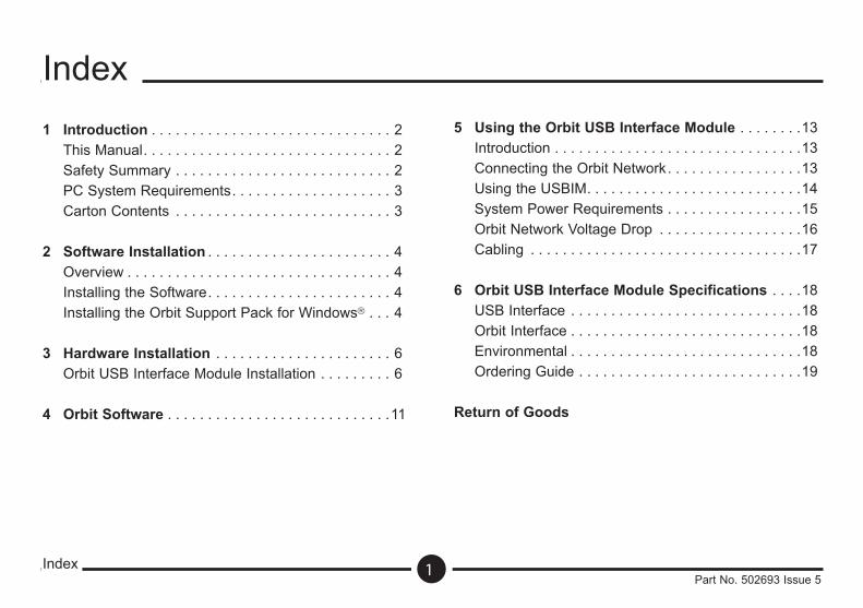
1 Introduction . . . . . . . . . . . . . . . . . . . . . . . . . . . . . . 2 This Manual. . . . . . . . . . . . . . . . . . . . . . . . . . . . . . . 2 Safety Summary . . . . . . . . . . . . . . . . . . . . . . . . . . . 2 PC System Requirements. . . . . . . . . . . . . . . . . . . . 3 Carton Contents . . . . . . . . . . . . . . . . . . . . . . . . . . . 3
2 Software Installation . . . . . . . . . . . . . . . . . . . . . . . 4 Overview . . . . . . . . . . . . . . . . . . . . . . . . . . . . . . . . . 4 Installing the Software. . . . . . . . . . . . . . . . . . . . . . . 4 Installing the Orbit Support Pack for Windows . . . 4
3 Hardware Installation . . . . . . . . . . . . . . . . . . . . . . 6 Orbit USB Interface Module Installation . . . . . . . . . 6 4 Orbit Software . . . . . . . . . . . . . . . . . . . . . . . . . . . .11
5 Using the Orbit USB Interface Module . . . . . . . .13 Introduction . . . . . . . . . . . . . . . . . . . . . . . . . . . . . . .13 Connecting the Orbit Network. . . . . . . . . . . . . . . . .13 Using the USBIM. . . . . . . . . . . . . . . . . . . . . . . . . . .14 System Power Requirements . . . . . . . . . . . . . . . . .15 Orbit Network Voltage Drop . . . . . . . . . . . . . . . . . .16 Cabling . . . . . . . . . . . . . . . . . . . . . . . . . . . . . . . . . .17
6 Orbit USB Interface Module Specifications . . . .18 USB Interface . . . . . . . . . . . . . . . . . . . . . . . . . . . . .18 Orbit Interface . . . . . . . . . . . . . . . . . . . . . . . . . . . . .18 Environmental . . . . . . . . . . . . . . . . . . . . . . . . . . . . .18 Ordering Guide . . . . . . . . . . . . . . . . . . . . . . . . . . . .19
Return of Goods
Index
Index
1Part No. 502693 Issue 5
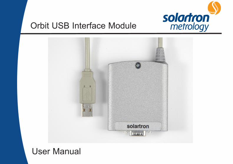
IntroductionThe Orbit USB Interface Module provides an interface to one Solartron Orbit Network. The module is designed to plug into a Type A USB socket on a PC.
This ManualThis manual describes the installation and preparation of the Orbit USB Interface Module, and the installation of the software drivers.
1.0: Introduction
1.0: Introduction
2Part No. 502693 Issue 5
Safety SummaryTerms in this manual:WARNING statements identify conditions or practices
that could result in personal injury or loss of life.
CAUTION statements identify conditions or practices that could result in damage to the equipment or other property.
Symbols in this manual:This symbol indicates where applicable cautionary or other information is to be found.
WARNINGS:Do not operate in an explosive atmosphereTo avoid explosion, do not operate this equipment in an explosive atmosphere.
NOTES:This equipment contains no user serviceable partsThis equipment must be returned to a Solartron Dealer for all service and repair.Low VoltageThis equipment operates at below the SELV and is therefore outside the scope of the Low Voltage Directive.
PC System RequirementsPC Hardware Requirements Personal or Multimedia computer with a Pentium
processor running at 700MHz or above with 128 MB or more RAM,
One available USB type A socket, Microsoft Windows 32 bit operating system
(Windows 98, Windows ME, Windows 2000, Windows XP, Windows NT4 (SP6) or later),
VGA or higher resolution video adaptor (Super VGA, 256-colour recommended),
Microsoft Mouse or compatible pointing device.
Carton ContentsThe Orbit USB Interface Module is supplied in a carton with the following accompanying items: T-Con (9 way D-Type plug to socket). 9-Way D-Type Terminator plug. Driver and installation software. This operating manual.
1.0: Introduction
1.0: Introduction (continued)
3Part No. 502693 Issue 5
OverviewSections 2 and 3 will guide you through the steps required to prepare and connect the Orbit USB Interface Module to a personal or multimedia computer or a compatible system.
Installing the SoftwareThe Orbit Support Pack for Windows Software must be installed BEFORE CONNECTING any Orbit USB Interface Modules to your computer.
Installing the Orbit Support Pack for Windows Software
To install the software follow the steps below
1. Close any open applications running on your PC.
2. Insert the Orbit Measurement System Software & Documentation CD into the appropriate drive. 3. Using Windows Start button, select Run.
4. Select Browse and look for SETUP.EXE on the CD ROM drive. Select and click OK.
2.0: Software Installation
2.0: Software Installation
4Part No. 502693 Issue 5
2.0: Software Installation
2.0: Software Installation (continued)
5Part No. 502693 Issue 5
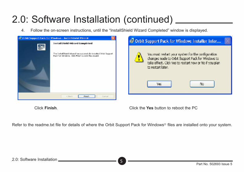
4. Follow the on-screen instructions, until the “InstallShield Wizard Completed” window is displayed.
Click Finish. Click the Yes button to reboot the PC
Refer to the readme.txt file for details of where the Orbit Support Pack for Windows files are installed onto your system.
Orbit USB Interface Module Installation
The Orbit USB Interface Module (USBIM) is designed to be connected to a USB Type A socket on your personal computer. Follow the steps below:
1. Before fitting the USBIM, install the Orbit Support Pack for Windows. Refer to section 2.0 Software Installation.
2. Insert the USB plug into any free USB Type A socket on the PC.
3. The PC will recognise the USBIM and, on some operating systems, will report that the USBIM has been connected. If the PC shows a message similar to the one shown overleaf please read the following information.
Please note that the following screen shots do not apply to all operating systems. Some operating systems may install the USBIM software automatically without any user intervention.
3.0: Hardware Installation
3.0: Hardware Installation
6Part No. 502693 Issue 5
3.0: Hardware Installation
3.0: Hardware Installation (continued)
7Part No. 502693 Issue 5
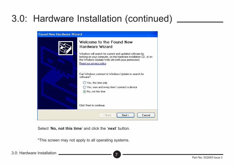
Select ‘No, not this time’ and click the ‘next’ button.
*This screen may not apply to all operating systems.
3.0: Hardware Installation
3.0: Hardware Installation (continued)
8Part No. 502693 Issue 5
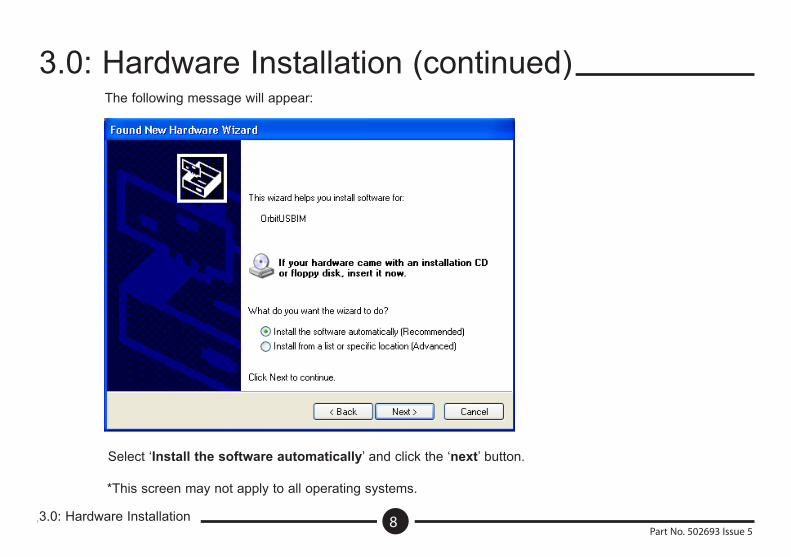
The following message will appear:
Select ‘Install the software automatically’ and click the ‘next’ button.
*This screen may not apply to all operating systems.
3.0: Hardware Installation
3.0: Hardware Installation (continued)
9Part No. 502693 Issue 5
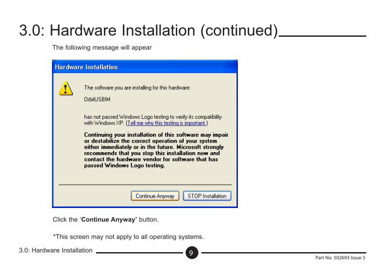
The following message will appear
Click the ‘Continue Anyway’ button.
*This screen may not apply to all operating systems.
3.0: Hardware Installation
3.0: Hardware Installation (continued)
10Part No. 502693 Issue 5
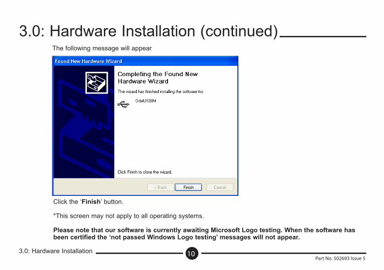
The following message will appear
Click the ‘Finish’ button.
*This screen may not apply to all operating systems.
Please note that our software is currently awaiting Microsoft Logo testing. When the software has been certified the ‘not passed Windows Logo testing’ messages will not appear.
4.0: Orbit Software
4.0: Orbit Software
11Part No. 502693 Issue 5
After installing the Orbit Support Pack for Windows the following components will have been loaded on the computer.
A dynamic link library (Orbit_IF.dll) that provides the interface between a 32 bit application and the Orbit Network via a Solartron Orbit PCI Network Card, Orbit ISA Network Card, RS232 Interface Module or USB Interface Module. The DLL supports most of the popular computer programming languages.
The Orbit Network Registration program (OrbitRegistration.exe) which allows you to register your Orbit Controller hardware (RS232 Interface Module or Orbit ISA Network Card). The Orbit Network Registration program does not have to be run when using the Orbit PCI Network card or USBIM. This program is activated using the Start menu at any time.
Orbit Network Explorer (OrbitExplorer.exe). This is a simple application program that allows the user to test each of the Orbit commands with a network of probes and to observe how the probes respond to these commands. You can also use this application to give you confidence that your Orbit system is operating correctly.
The Orbit COM Library, which gives a language independent interface to the Orbit Measurement System. See the Orbit COM Library Programmers Manual for further information.
Code examples and support files for COM, DLL and DOS applications.
Orbit Network ExplorerTo select the USBIM use the network - setup menu. The USBIM will appear in the ‘Orbit Network Selection’ dialog box as ‘Orbit USBIM (ssssssssss)’ where ‘ssssssssss’ is the serial number of the USBIM.
Multiple Orbit USB Interface Module’s will be listed in Orbit Network Selection as shown below
OrbitUSBIM (xxxxxxxxxx) OrbitUSBIM (yyyyyyyyyy) OrbitUSBIM (zzzzzzzzzz) etc....
Where xxx..., yyy..., and zzz... are the serial numbers of the installed USBIM’s.
4.0: Orbit Software
4.0: Orbit Software (continued)
12Part No. 502693 Issue 5
IntroductionThe Orbit USB Interface Module, USBIM, provides a simple interface between personal computers and the Orbit Network. It is suitable for applications where an Orbit PCI Network Card cannot be used, such as in notebook computers and field devices.The computers USB port will allow a maximum of four Orbit modules to be controlled via the USBIM without the need for a separate power supply. The addition of a Power Supply Interface Module (PSIM) can extend the capability of the USBIM to control up to 31 Orbit modules.The USBIM is Orbit backward compatible and fully supports all Orbit functions except the dynamic measurement feature.
Connecting the Orbit NetworkIf the USBIM is still connected to your PC it is recommended that it is unplugged before the Orbit modules (and PSIM if used) are connected to the USBIM, this will avoid any power supply disturbances created by plugging Orbit modules into a ‘hot’ nework. Once the network is fully connected, plug the USBIM plug into the USB socket on the PC.
5.0: Using the Orbit USB Interface Module
5.0: Using the Orbit USB Interface Module
13Part No. 502693 Issue 5
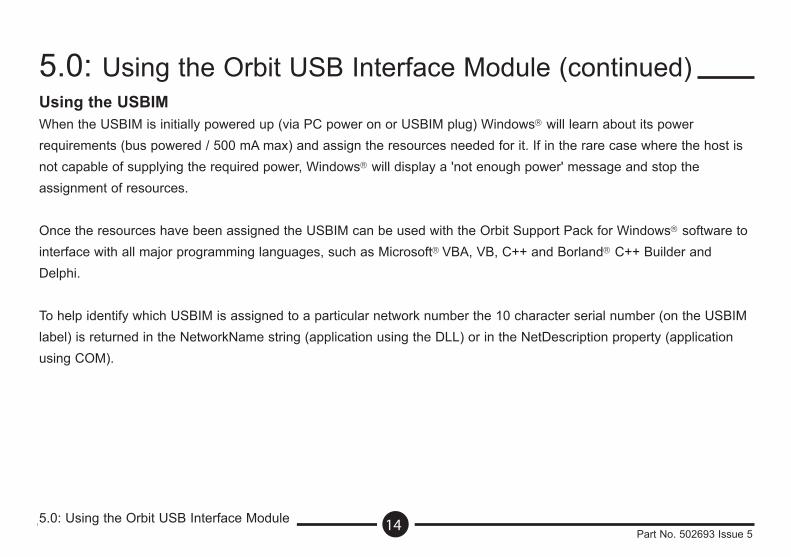
Using the USBIMWhen the USBIM is initially powered up (via PC power on or USBIM plug) Windows will learn about its power requirements (bus powered / 500 mA max) and assign the resources needed for it. If in the rare case where the host is not capable of supplying the required power, Windows will display a 'not enough power' message and stop the assignment of resources.
Once the resources have been assigned the USBIM can be used with the Orbit Support Pack for Windows software to interface with all major programming languages, such as Microsoft VBA, VB, C++ and Borland C++ Builder and Delphi.
To help identify which USBIM is assigned to a particular network number the 10 character serial number (on the USBIM label) is returned in the NetworkName string (application using the DLL) or in the NetDescription property (application using COM).
5.0: Using the Orbit USB Interface Module
5.0: Using the Orbit USB Interface Module (continued)
14Part No. 502693 Issue 5
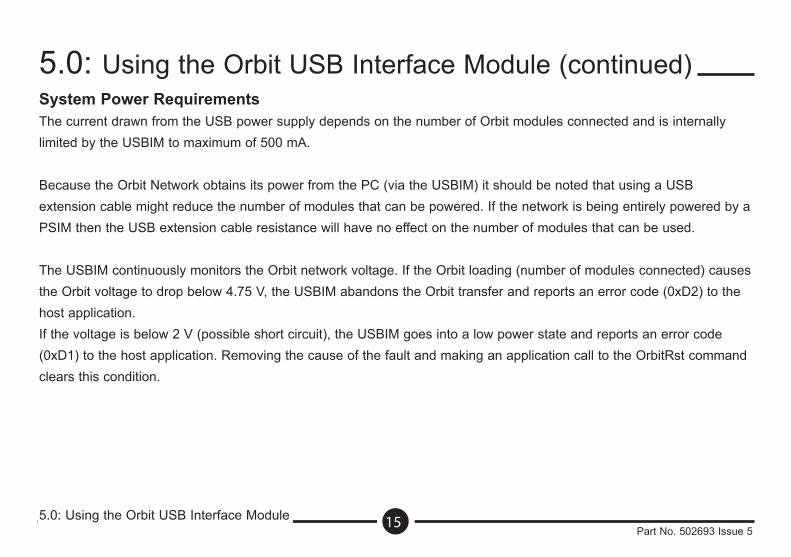
System Power RequirementsThe current drawn from the USB power supply depends on the number of Orbit modules connected and is internally limited by the USBIM to maximum of 500 mA.
Because the Orbit Network obtains its power from the PC (via the USBIM) it should be noted that using a USB extension cable might reduce the number of modules that can be powered. If the network is being entirely powered by a PSIM then the USB extension cable resistance will have no effect on the number of modules that can be used.
The USBIM continuously monitors the Orbit network voltage. If the Orbit loading (number of modules connected) causes the Orbit voltage to drop below 4.75 V, the USBIM abandons the Orbit transfer and reports an error code (0xD2) to the host application.If the voltage is below 2 V (possible short circuit), the USBIM goes into a low power state and reports an error code (0xD1) to the host application. Removing the cause of the fault and making an application call to the OrbitRst command clears this condition.
5.0: Using the Orbit USB Interface Module
5.0: Using the Orbit USB Interface Module (continued)
15Part No. 502693 Issue 5
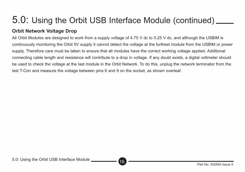
Orbit Network Voltage DropAll Orbit Modules are designed to work from a supply voltage of 4.75 V dc to 5.25 V dc, and although the USBIM is continuously monitoring the Orbit 5V supply it cannot detect the voltage at the furthest module from the USBIM or power supply. Therefore care must be taken to ensure that all modules have the correct working voltage applied. Additional connecting cable length and resistance will contribute to a drop in voltage. If any doubt exists, a digital voltmeter should be used to check the voltage at the last module in the Orbit Network. To do this, unplug the network terminator from the last T-Con and measure the voltage between pins 6 and 9 on the socket, as shown overleaf.
5.0: Using the Orbit USB Interface Module
5.0: Using the Orbit USB Interface Module (continued)
16Part No. 502693 Issue 5
5.0: Using the Orbit USM Interface Module
5.0: Using the Orbit USB Interface Module (continued)
17Part No. 502693 Issue 5
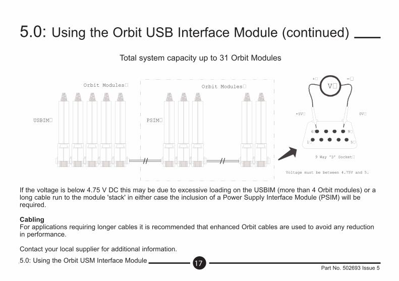
Voltage must be between 4.75V and 5.25V DC�
PSIM�USBIM�
Orbit Modules� Orbit Modules�
9 Way 'D' Socket�
V�
1� 5�
6� 9�
0V�+5V�
+� -�
If the voltage is below 4.75 V DC this may be due to excessive loading on the USBIM (more than 4 Orbit modules) or a long cable run to the module 'stack' in either case the inclusion of a Power Supply Interface Module (PSIM) will be required.
CablingFor applications requiring longer cables it is recommended that enhanced Orbit cables are used to avoid any reduction in performance.
Contact your local supplier for additional information.
Total system capacity up to 31 Orbit Modules
6.0: Orbit USB Interface Module Specification
6.0: Orbit USB Interface Module Specification
18Part No. 502693 Issue 5
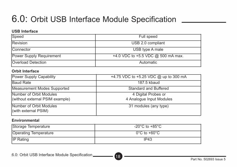
USB InterfaceSpeed Full speedRevision USB 2.0 compliantConnector USB type A malePower Supply Requirement +4.0 VDC to +5.5 VDC @ 500 mA max.Overload Detection Automatic
Orbit Interface
Number of Orbit Modules (without external PSIM example)
Power Supply Capability +4.75 VDC to +5.25 VDC @ up to 300 mABaud Rate 187.5 kbaudMeasurement Modes Supported Standard and Buffered
4 Digital Probes or 4 Analogue Input Modules
Number of Orbit Modules (with external PSIM)
31 modules (any type)
EnvironmentalStorage Temperature -20°C to +85°COperating Temperature 0°C to +60°CIP Rating IP43
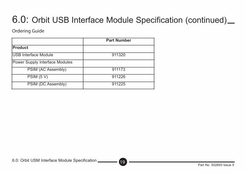
Ordering Guide
6.0: Orbit USM Interface Module Specification
6.0: Orbit USB Interface Module Specification (continued)
19Part No. 502693 Issue 5
Part Number
Product
USB Interface Module 911320
Power Supply Interface Modules
PSIM (AC Assembly) 911173
PSIM (5 V) 911226
PSIM (DC Assembly) 911225