
ORBIMAT 165 CA ORBIMAT 300 CA - E H Wachsehwachs.com/resources/pdf/prodmanual-20130506145003.pdf ·...
80
Operating instructions for operators and machine users Orbital Welding Power Supplies ORBIMAT CAdvanced ORBIMAT 165 CA ORBIMAT 300 CA Machine No: Please read all operating instructions before commissioning this machine so that you can work with it safely. Retain the operating instructions for future use.
Transcript of ORBIMAT 165 CA ORBIMAT 300 CA - E H Wachsehwachs.com/resources/pdf/prodmanual-20130506145003.pdf ·...

Operating instructionsfor operators and machine users
Orbital Welding Power Supplies
ORBIMAT CAdvanced
ORBIMAT 165 CAORBIMAT 300 CA
Machine No:
Please read all operating instructions before commissioning this machine so that you can work with it safely.Retain the operating instructions for future use.

2 | orbitalum tools GmbH, D-78224 Singen, www.orbitalum.com, Tel. +49 (0) 77 31 792-0 (01.2012) OM_BA_ORBIMAT_CA_01_EN
ORBIMAT CA | Operating instructions
1. ABOUT THIS INSTRUCTIONS..................................41.1 Warnings ...................................................41.2 Other symbols and labels ...........................41.3 Abbreviations ............................................41.4 Warning signs ............................................5
2. OWNER INFORMATION AND SAFETY PRECAUTIONS ..........................................6
2.1 Duties of the owner ....................................62.2 Use of the machine .....................................6
2.2.1 Intended purpose.............................62.2.2 Improper use ...................................62.2.3 Limits of the product ........................6
2.3 Basic safety precautions ............................7
3. LAYOUT OF THE PRODUCT ...................................103.1 ORBIMAT 165 CA ......................................103.2 ORBIMAT 300 CA ......................................113.3 Integrated compact cooling* ....................113.4 Accessories .............................................12
3.4.1 ORBICAR W trolley with integrated water coolant .................................12
3.4.2 ORBICOOL W ..................................123.4.3 ORBICOOL Active ...........................123.4.4 ORBITWIN switching device ............123.4.5 ORBICAR S trolley ..........................123.4.6 ORBTROLLEY ..................................133.4.7 Durable carrying case ....................133.4.8 BUP Control Box .............................133.4.9 Oxygen meter ORB 1001 ................133.4.10 ORBIPURGE forming set..................133.4.11 CompactFlash Card 32 MB ..............133.4.12 Soft-/Hardware package ................143.4.13 Remote control with cable ..............143.4.14 Paper roll for integrated printer ......143.4.15 Ribbon cartridge for integrated
printer ...........................................143.4.16 Anti freeze .....................................14
4. CHARACTERISTICS AND RANGE OF APPLICATIONS ...................................................15
4.1 Characteristics .........................................154.2 Additional characteristics .........................16
4.2.1 ORBIMAT 165 CA ............................164.2.2 ORBIMAT 300 CA Compact .............164.2.3 ORBIMAT 300 CA AC/DC .................164.2.4 ORBIMAT 300 CA AC/DC Compact ...164.2.5 ORBIMAT 300 CA AVC/OSC .............16
4.3 Functional description ..............................16
5. TECHNICAL DATA ................................................175.1 System data .............................................17
5.1.1 Components and parts ...................175.1.2 Technical Data ...............................17
6. COMMISSIONING ...............................................196.1 Checking scope of delivery .......................196.2 Scope of delivery .....................................19
7. SETUP AND ASSEMBLY .......................................207.1 Control elements ......................................20
7.1.1 Overview of the main control elements .......................................20
7.1.2 Connections and control elements on the front panel ...............................20
7.1.3 Operating concept..........................217.1.4 Operation via the rotary knob .........227.1.5 Operation via push switches
(softkeys) ......................................227.1.6 Operation via an external keyboard 22
7.2 Connection of the power source ................237.2.1 Connecting gas bottle and weld head
.....................................................237.3 Commissioning ........................................24
7.3.1 Adding anti-freeze and water ..........257.3.2 Commissioning water pump ...........25
8. OPERATION ........................................................298.1 Auto programming ...................................29
8.1.1 Setting parameters ........................298.2 Testing the procedure ...............................31
8.2.1 Preparing weld head ......................318.2.2 Connecting forming gas .................328.2.3 Welding .........................................338.2.4 Interrupting the welding process ....34
8.3 Adjusting the procedure ...........................358.3.1 Reasons and steps for adjusting
procedure ......................................358.3.2 Making percental changes ..............358.3.3 Adjusting individual parameters .....368.3.4 Adjusting gas times .......................368.3.5 Adjusting ignition current, end current
and current slope-off .....................378.3.6 Adjusting the pool formation time ..388.3.7 Adjusting welding current and
transition times ("Slope") ...............388.3.8 Adjusting pulse times ................... 40
TABLE OF CONTENTS

(01.2012) OM_BA_ORBIMAT_CA_01_EN orbitalum tools GmbH, D-78224 Singen, www.orbitalum.com, Tel. +49 (0) 77 31 792-0 | 3
ORBIMAT CA | Operating instructions
All rights reserved, particularly the right to copy, distribute and translate. Duplication or reproduction in any form (print, photocopy, microfilm or data capture) requires written permission from Orbitalum Tools GmbH.
8.3.9 Adjusting weld speed and transition time ("Slope") ............................... 40
8.3.10 Changing the sector .......................428.4 Saving and calling up a procedure ........... 44
8.4.1 Saving a procedure ....................... 448.4.2 Calling up a procedure .................. 44
8.5 Locking machine with key switch ..............458.6 Tacking function ...................................... 468.7 Using the second gas pressure level ("flow
force") .....................................................478.8 Connecting supplementary devices ..........47
8.8.1 ORB 1001 Residual Oxygen Meter...478.8.2 Connecting and configuring the BUP
control unit ................................... 488.8.3 TIG manual welding torch .............. 488.8.4 External remote control ..................498.8.5 External printer (A4) .......................498.8.6 External monitor/LCD (VGA) ............49
8.9 Monitoring functions ................................508.9.1 General information .......................508.9.2 Adjusting limit values .....................508.9.3 Grenzwerte anpassen ....................50
8.10 Data documentation and data management ...............................................................518.10.1 Managing data ...............................518.10.2 Entering comments and application
data ("Process details") .................528.10.3 Working with external memory cards
.....................................................538.10.4 Viewing and printing data ..............548.10.5 Editing data on a PC with the
"OrbiProgCA" supplemental software .....................................................55
8.11 Updating and backup functions for the software ..................................................55
8.12 Updating software components ................568.13 Saving software components ...................568.14 Restoring software components ...............568.15 Working in other languages ......................56
8.15.1 Changing the language ..................568.15.2 Printing data in another language ...578.15.3 Creating a new operating language .57
8.16 Importing programs from other ORBIMATIC power sources .........................................57
8.17 Special keyboard commands ....................578.18 Operation of the system with other mains
voltages (OM 165 CA only) ........................58
9. SERVICE AND TROUBLESHOOTING ......................599.1 Performing service work ...........................59
9.1.1 Pumping out water .........................599.1.2 Performing motor calibration ..........599.1.3 Adjusting an external printer ........ 609.1.4 Switching on an internal printer ..... 609.1.5 Printing a test page ........................619.1.6 Service screen ...............................619.1.7 Info................................................62
9.2 Possible application/operating errors .......629.2.1 Uneven weld seam ("current
fluctuations") ................................629.2.2 Annealing colors inside/outside .....629.2.3 Wide seam and no weld penetration
.....................................................639.2.4 Uneven seam/hole formation at the
end of welding ...............................639.2.5 Ignition problems ...........................639.2.6 Machine does not start ................. 64
9.3 List of error messages ............................. 649.4 Status LED indicators .............................. 689.5 Temporarily deactivating sensors and
monitoring functions ................................719.6 Setting date and time ...............................72
10. MAINTENANCE, SERVICE AND REMEDYING ERRORS .........................................................................73
10.1 Maintenance ............................................7310.1.1 Maintenance intervals ....................7310.1.2 Storage..........................................74
10.2 Service/Customer service .........................74
11. ENVIRONMENTAL PROTECTION AND DISPOSAL ....7511.1 Electric tools and accessories ...................75
12. OVERVIEW WIRING DIAGRAM ..............................76
13. EC DECLARATION OF CONFORMITY ......................7713.1 ORBIMAT 165 CA | 300 CA ........................77

4 | orbitalum tools GmbH, D-78224 Singen, www.orbitalum.com, Tel. +49 (0) 77 31 792-0 (01.2012) OM_BA_ORBIMAT_CA_01_EN
ABOUT THIS INSTRUCTIONS ORBIMAT CA | Operating instructions
1. ABOUT THIS INSTRUCTIONS
For quick comprehension of these instructions and safe handling of the machine, the warnings, notes and symbols used in the instructions are presented here, as are their meanings.
1.1 WarningsWarnings are used in these instructions to warn you of injury or damage to property.
X Always read and heed these warnings!
This is the warning symbol. It warns you of the danger of injury. X Carry out all measures identified with the safety symbol to avoid injury or death.
Warning symbol Meaning
DANGER
Immediate danger!Non-compliance can result in death or very serious injury.
[ Prohibited activities (if applicable). X Measures for avoiding danger.
WARNING
Possible danger!Non-compliance can result in serious injury.
X Prohibited activities (if applicable). [ Measures for avoiding danger.
CAUTION
Dangerous situation!Non-compliance can result in minor injury.
X Measures for avoiding danger.
CAUTIONDangerous situation!Non-compliance can result in damage to property.
X Measures for avoiding danger.
1.2 Other symbols and labelsSymbol Meaning
Note: Include important information for comprehension.
Imperative: You must heed this symbol.
1. si Action instruction in a sequence of actions: You must carry out an action here.
X Single action instruction: You must carry out an action here.
Z Conditional action instruction: You must carry out an action here if the preceding condition is fulfilled.
1.3 AbbreviationsAbbr. Meaning
OM ORBIMAT
CA CAdvanced

(01.2012) OM_BA_ORBIMAT_CA_01_EN orbitalum tools GmbH, D-78224 Singen, www.orbitalum.com, Tel. +49 (0) 77 31 792-0 | 5
ORBIMAT CA | Operating instructions ABOUT THIS INSTRUCTIONS
1.4 Warning signs X Heed all warnings and safety precautions found on the machine.
The following information is also found on the machine:
Image Machine model Position on the machine
Meaning Code No.
ORBIMAT 165 CAORBIMAT 300 CA
Rear Danger: Danger of injury from electric shock
-
ORBIMAT 165 CAORBIMAT 300 CA
Rear Warning: Danger of injury from electric shock
-

6 | orbitalum tools GmbH, D-78224 Singen, www.orbitalum.com, Tel. +49 (0) 77 31 792-0 (01.2012) OM_BA_ORBIMAT_CA_01_EN
OWNER INFORMATION AND SAFET Y PRECAUTIONS ORBIMAT CA | Operating instructions
2. OWNER INFORMATION AND SAFETY PRECAUTIONS
2.1 Duties of the owner• Workshop/outdoor/field use: The owner is responsible for safety in the dangerous area of the machine and ensures
that only trained personnel operate the machine and occupy the dangerous area.
• Employee safety: The owner is responsible for complying with the safety regulations described and for safety- conscious working with all prescribed safety equipment see Sec. 2.3, Page 7.
2.2 Use of the machine
2.2.1 Intended purpose
The orbital welding systems (Power Sources CA/CB 165/300 and Orbitwin in conjunction with the orbital weld heads of the OW/OWS/TP/P/OP/HX series and the accessories recom-mended by the manufacturer) are used for the welding of ferritic, uncoated pipes up to the pipe circumferences specified by the heads and maximum possible pipe walls using the Tungsten Inert Gas process (TIG) with a direct current arc, and if specified, with an alterna-ting current arc.
X Heed the safety precautions in these operating instructions. X Heed the safety precautions in the operating instructions of the accessories and other
machines. X Comply with inspection and maintenance intervals. X Use machine only in its original state. Use only genuine accessories, spare parts and
operating materials. X Do not remove safety devices or modify their function. X Use the machine only on empty, unpressurized pipes and containers in a non-
explosive atmosphere.
2.2.2 Improper use
Any use that differs from or goes beyond the use specified under "Intended purpose" is improper. The owner shall be responsible for any damage which results from improper use.The machine is not intended for use by the private consumer.It is impermissible to remove safety devices or operate the machine without the safety devices.It is impermissible to exceed the technical values specified for normal operation..
2.2.3 Limits of the product
• Workplace: In pipe preparation, plant construction or in the plant
• Space requirement/Movement space: Radial space requirement of approx. 2 meters around the machine for operating personnel.
• Working illumination: At least 300 Lux.
• Maintenance, see Sec. 10.1, Page 72
• Age of operating personnel: At least 14 years old and without physical impairments.
• Qualification of operating personnel: Instructed person with professional training in welding technology.
• Operation by one person
• Climate conditions:Temperature range for machine operation: –10 °C to 40 °C, (< 70% rel. humidity). Temperature range for machine storage: –20 °C to 40 °C, (< 70% rel. humidity).
X Do not work in misty, rainy or stormy conditions outside. Cooling is only ensured with a full water tank.
(01.2012) OM_BA_ORBIMAT_CA_01_EN orbitalum tools GmbH, D-78224 Singen, www.orbitalum.com, Tel. +49 (0) 77 31 792-0 | 7
ORBIMAT CA | Operating instructions OWNER INFORMATION AND SAFET Y PRECAUTIONS
2.3 Basic safety precautionsAll products produced and sold by Orbitalum Tools GmbH are built for safe use using state-of-the-art technology. Remaining risks are described in the following operating instructions. Using the equipment in a way other than as described in the operating instructions can lead to serious personal injury and damage to property.
• Heed and comply with safety precautions.
• Store all documentation near the machine.
• Heed country-specific regulations, accident-prevention regulations, standards and guidelines.
• Use the machine only in proper operating order. Heed information on maintenance (see Sec. 10.1, Page 72).
• Report deviations in operating behavior of the machine to the person in charge immediately.
• Use only the dimensions and materials listed in these instructions. Other materials may only be used after consulting with Orbitalum Tools customer service.
• Use only genuine tools, spare parts, operating materials and accessories from Orbitalum Tools.
• Repair and maintenance work on the electrical equipment may only be carried out by a qualified electrician.
• Switch the machine off, let it stop running and unplug the power plug after using it, before transporting it, before changing tools and before carrying out cleaning, adjustment and repair work.
• Do not carry machine by the hose assembly. Protect machine cabling from heat, oil and sharp edges.
• Do not reach into the tools during operation.
• Ensure that the workpiece is clamped properly.
• Only switch on the machine if a pipe is clamped.
• When working with the machine, wear safety shoes as per EN ISO 20345 (at least S1).
• When working with the machine, wear safety shoes in accordance with EN ISO 20345 (at leastS1)
• In extreme usage conditions, conductive dust can settle inside the machine. Z Have a professional electrician install an SPE-PRCD or ground-fault circuit (30 mA) between the mains
network and the machine.
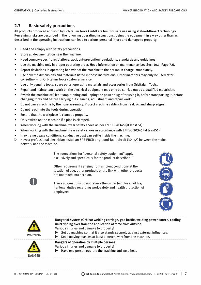
The suggestions for "personal safety equipment" apply exclusively and specifically for the product described.
Other requirements arising from ambient conditions at the location of use, other products or the link with other products are not taken into account.
These suggestions do not relieve the owner (employer) of his/her legal duties regarding work-safety and health protection of employees.
WARNING
Danger of system (Orbicar welding carriage, gas bottle, welding power source, cooling unit) tipping over from the application of force from outside.Various injuries and damage to property!
X Set up machine so that it also stands securely against external influences. X Keep moving masses at least 1 meter away from the machine.
DANGER
Dangers of operation by multiple persons.Various injuries and damage to property!
X Have one person operate the machine and weld head.

8 | orbitalum tools GmbH, D-78224 Singen, www.orbitalum.com, Tel. +49 (0) 77 31 792-0 (01.2012) OM_BA_ORBIMAT_CA_01_EN
OWNER INFORMATION AND SAFET Y PRECAUTIONS ORBIMAT CA | Operating instructions
DANGER
Dangers of improper maintenance of the system.Various injuries and damage to property!
X Carry out maintenance as described in the "Maintenance" chapter.
DANGER
Electrical hazards through touching and incorrect or damp safety equipment. Electric shock!
[ Do not touch energized parts (pipe), especially when igniting the arc. [ Do not allow persons with increased sensitivity to electrical hazards
(e.g. weakness of the heart) to work with the machine. X Wear dry safety shoes, dry metal-free (grommet-free) leather gloves and dry safety
suits to minimize the electrical hazard. X Work on a dry surface.
DANGER
Accidental ignition.Electric shock!
X Switch off the orbital welding power source when connecting or disconnecting a weld head.
WARNING
Electromagnetic incompatibility of surrounding devices during high-frequency ignition and devices in operation without a protective ground.Various injuries and damage to property!
X Use only electrical devices with protective insulation in the working area of the welding system.
X Observe electromagnetically-sensitive devices when igniting the system.
WARNING
Ultraviolet radiation from the arc while welding.Damage to eyes and burning of skin!
X During operation, wear eye protection as per EN 170 and skin-covering safety clothing.
X With closed weld heads, ensure proper working order of the eye protection.
WARNING
Hot leaking liquids and hot plug connections during heavy operation.Danger of scalding!
X Heed the safety precautions of the technical supervisor/person in charge of safety.
DANGER
Incorrect handling of pressure tanks and other parts of the system (e.g. forming gas bottle).Various injuries and damage to property!
X Heed safety regulations, especially those for pressure tanks. X Comply with safety data sheets. X If the system and its components exceed 25 kg in weight, lift using several people or
lifting equipment.
DANGER
Flammable material near the welding zone or solvent in the room air.Danger of explosion and fire!
[ Do not weld near solvents (e.g. where painting is being carried out). [ Do not weld near explosive substances. [ Do not use flammable materials as a base in the welding area. X Ensure that no flammable materials or soiling is located near the machine.
CAUTION
Hot surfaces of the weld head and weld points, including for a period of time after welding.Danger of burns!
X Wear safety gloves.

(01.2012) OM_BA_ORBIMAT_CA_01_EN orbitalum tools GmbH, D-78224 Singen, www.orbitalum.com, Tel. +49 (0) 77 31 792-0 | 9
ORBIMAT CA | Operating instructions OWNER INFORMATION AND SAFET Y PRECAUTIONS
WARNING
Poisonous vapors and substances during the welding process and handling of the electrodes.Health problems, including cancer!
X Use extraction devices as per the professional association regulations (e.g. BGI: 7006-1).
X Extra caution is required with chrome, nickel and manganese. [ Do not use electrodes containing thorium.
DANGER
Faulty ignition in case of non-connected or incorrectly positioned weld head.Electric shock, bodily injury and damage to property at other devices as well!
[ Do not play with weld head. X If the weld head is not ready for operation, switch it to the "Test" function.
DANGER
Improper access to and opening of the ORBIMAT system.Electric shock!
X Disconnect system from mains. X Disconnect all external devices connected to the machine (weld heads etc.). X Allow machine to cool down sufficiently before opening. X Allow only a professional electrician to access the electrical system. [ Never connect an opened system to the mains network.
DANGER
Liquid in the housing due to improper use and transport.Electric shock!
[ Do not place liquids (drinks) on the system. X Do not block ventilation slots. X Check housing interior for moisture after transporting the machine and leave it
open to air it out if necessary.
DANGER
Damaged plugs. Electric shock!
[ Do not use adapter plugs together with protectively grounded power tools. X Ensure that the connecting plugs of the machine fit into the outlet.
DANGER
Catching of loose/long clothing, long hair or jewelry by rotating machine parts. Very serious injury!
[ Do not wear loose/long clothing, e.g. ties, when operating the equipment. X Secure long hair against being caught.
DANGER
Defective safety parts due to soiling and wear.Bodily injury due to failure of safety parts!
X Replace defective safety parts immediately. X Check safety parts daily for proper operation. X Check machine daily for externally visible damage and defects.
Have a professional remedy the damage and defects immediately.

10 | orbitalum tools GmbH, D-78224 Singen, www.orbitalum.com, Tel. +49 (0) 77 31 792-0 (01.2012) OM_BA_ORBIMAT_CA_01_EN
LAYOUT OF THE PRODUCT ORBIMAT CA | Operating instructions
3. LAYOUT OF THE PRODUCT
3.1 ORBIMAT 165 CA
9
1
2
3
4
5
6
7
8
10
11
1. Display housing2. Printer cover3. Intregrated Printer4. Rotary knob5. Multicard reader6. Flowmeter7. Front panel8. Main switch9. Hood10. Softkeys11. 10.5" color display
Fig. 1: Layout of Orbimat 165 CA
(01.2012) OM_BA_ORBIMAT_CA_01_EN orbitalum tools GmbH, D-78224 Singen, www.orbitalum.com, Tel. +49 (0) 77 31 792-0 | 11
ORBIMAT CA | Operating instructions LAYOUT OF THE PRODUCT
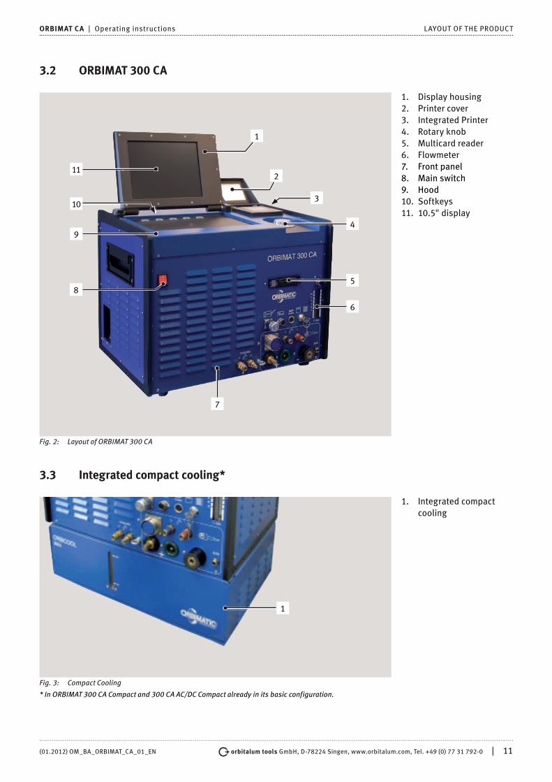
3.2 ORBIMAT 300 CA
4
6
7
8
9
10
11
5
2
3
1
1. Display housing2. Printer cover3. Integrated Printer4. Rotary knob5. Multicard reader6. Flowmeter7. Front panel8. Main switch9. Hood10. Softkeys11. 10.5" display
Fig. 2: Layout of ORBIMAT 300 CA
3.3 Integrated compact cooling*
1
1. Integrated compact cooling
Fig. 3: Compact Cooling
* In ORBIMAT 300 CA Compact and 300 CA AC/DC Compact already in its basic configuration.

12 | orbitalum tools GmbH, D-78224 Singen, www.orbitalum.com, Tel. +49 (0) 77 31 792-0 (01.2012) OM_BA_ORBIMAT_CA_01_EN
LAYOUT OF THE PRODUCT ORBIMAT CA | Operating instructions
3.4 AccessoriesNot included in scope of delivery.
WARNING
Danger from insufficiently secured accessories!Various injuries and damage to property.
X Use only accessories, spare parts and operating materials developed and approved by the manufacturer.
3.4.1 ORBICAR W trolley with integrated water coolant
Article Suitable for ORBIMAT Code kg
ORBICAR W trolley with integrated water coolant 300 CB, 300 CA, 300 CA AC/DC 884 000 002 58,200
3.4.2 ORBICOOL W
Article Suitable for ORBIMAT Code kgORBICOOL W 300 CB, 300 CA, 300 CA AC/DC 885 000 002 26,000
3.4.3 ORBICOOL Active
Article Code kgORBICOOL Active for OM 165 889 000 001 40,000ORBICOOL Active for OM 300 889 000 002 40,000
3.4.4 ORBITWIN switching device
Article Suitable for ORBIMAT Code kgORBIMAT 165 CB switching device 165 CB 860 000 001 8,800ORBIMAT 165 CA switching device 165 CA 861 000 001 8,800ORBITWIN 300 switching device* all ORBIMAT 300 876 000 001 8,800*not suitable for AVC/OSC machines.
3.4.5 ORBICAR S trolley
Article Code kgORBICAR S trolley 884 000 001 19,100

(01.2012) OM_BA_ORBIMAT_CA_01_EN orbitalum tools GmbH, D-78224 Singen, www.orbitalum.com, Tel. +49 (0) 77 31 792-0 | 13
ORBIMAT CA | Operating instructions LAYOUT OF THE PRODUCT
3.4.6 ORBTROLLEY
Article Code kgORBTROLLEY 884 000 003 -
3.4.7 Durable carrying case
Article Suitable for ORBIMAT Code kgCarrying case 165 CB, 165 CA 875 050 002 17,500Carrying case 300 CB, 300 CA, 300 CA AC/DC 874 050 001 20,800
3.4.8 BUP Control Box
Article Suitable for ORBIMAT Code kgBUP Control Box 165 CA, 300 CA 886 000 001 2,700
3.4.9 Oxygen meter ORB 1001
Article Version Code kgOxygen meter ORB 1001 230 - 115 V, 50/60 Hz, single-phase 882 000 001 3,100
3.4.10 ORBIPURGE forming set
Article Tube ID [mm] Tube ID [inch] Code kgORBIPURGE forming set 12,0 - 110,0 0.472 - 4.331 881 000 001 3,150
3.4.11 CompactFlash Card 32 MB
Article Code kgCompactFlash Card 32 MB 875 0102 056 0,010

14 | orbitalum tools GmbH, D-78224 Singen, www.orbitalum.com, Tel. +49 (0) 77 31 792-0 (01.2012) OM_BA_ORBIMAT_CA_01_EN
LAYOUT OF THE PRODUCT ORBIMAT CA | Operating instructions
3.4.12 Soft-/Hardware package
Article Code kgSoft-/Hardware package 875 050 003 0,200 3.4.13 Remote control with cable
Article Cable length [m] Cable length [ft] Code kgRemote control with cablel 7,5 24,6 875 050 001 1,350 3.4.14 Paper roll for integrated printer
Article Code kgPaper roll for integrated printer (contains 3 paper rolls) 875 050 017 0,150 3.4.15 Ribbon cartridge for integrated printer
Article Code kgRibbon cartridge for integrated printer CA 875 030 004 0,010Ribbon cartridge for integrated printer CB 875 030 002 0,020
3.4.16 Anti freeze
Article Code kgAnti freeze 1 Liter 875 030 011 1,350

(01.2012) OM_BA_ORBIMAT_CA_01_EN orbitalum tools GmbH, D-78224 Singen, www.orbitalum.com, Tel. +49 (0) 77 31 792-0 | 15
ORBIMAT CA | Operating instructions CHARACTERISTICS AND RANGE OF APPLICATIONS
4. CHARACTERISTICS AND RANGE OF APPLICATIONS
4.1 CharacteristicsOperating concept, functions and equipment of the ORBIMAT CA series (basic configuration):
• ORBIMATIC auto programming with programming aid via entry of pipe diameter, wall thickness,material and weld gas.
• ORBIMAT CA models: FLOW FORCE for reducing the gas pre purge time with closed weld heads(standard configuration).
• BUP control function with monitored, position-dependent pipe internal-pressure control (optional).
• Operation by multifunctional rotary knob.
• DC direct current welding.
• Control option for cold wire supply.
• 10.5" swiveling monitor.
• Storage capacity for over 5,000 procedures.Procedure management through the creation of folder structures.
• Welding data logging and printing of actual values.
• Multicard reader for data transfer to external PC.
• Memory expansion and data exchange possible via CompactFlash card (CF), SD, MMC, SM, Sony Memory Stick.
• PC Offline software (optional) with conversion option for data logs to PDF and Excel files.
• Service functions via PSS (Pro Service System): – Function checking even without opening the system. – Maintenance and exchange of parts via systematic component layout.
• Current and motor slope setting between the individual sectors.
• Monitoring of cooling water and weld gas.
• Programming of up to 99 sectors possible.
• VGA port.
• Built-in printer.

16 | orbitalum tools GmbH, D-78224 Singen, www.orbitalum.com, Tel. +49 (0) 77 31 792-0 (01.2012) OM_BA_ORBIMAT_CA_01_EN
CHARACTERISTICS AND RANGE OF APPLICATIONS ORBIMAT CA | Operating instructions
4.2 Additional characteristics
4.2.1 ORBIMAT 165 CA
• Integrated water cooling system for cooling the connected welding heads.
• WIDE RANGE input voltages for safe operation of power sets or voltage networks with extreme fluctuations in voltage – ideal for mobile use on building sites.
4.2.2 ORBIMAT 300 CA Compact
• Integrated compact cooling.
4.2.3 ORBIMAT 300 CA AC/DC
• Alongside the benefits of the ORBIMAT 300 CA power supply, this device also offers the option of AC welding.
• Option to set a positive and negative half-cycle in the ratio 20 - 80%.
• Frequency setting 50 - 200 Hz.
• Detection of actual values for the welding reports in the DC regime.
4.2.4 ORBIMAT 300 CA AC/DC Compact
• Integrated compact cooling.
• Alongside the benefits of the ORBIMAT 300 CA power supply, this device also offers the option of AC welding.
• Option to set a positive and negative half-cycle in the ratio 20 - 80%.
• Frequency setting 50 - 200 Hz.
• Detection of actual values for the welding reports in the DC regime.
4.2.5 ORBIMAT 300 CA AVC/OSC
• The new ORBIMATIC arc voltage control calculates and programs the length of the arc automatically in "mm" from the current voltage characteristics. This avoids the usual time spent calculating the necessary arc voltage each time the weld power changes to maintain the arc at a consistent length in the individual sectors.
• During oscillation each of the edge holding times can be synchronized with the high-pulse settings.
• The center of the seam can be accessed manually and be determined using an automatic scanner. The electrode accesses each of side of the seam and then calculates the center of the path automatically. For asymmetric weld seam configurations this is compensated by an OFFSET function.
• These functions are also shown graphically on the display for easier understanding.
• Remote control (cable length: 7.5 m)
• All the relevant functions can initially be changed even during the welding process by means of the remote control that forms part of the standard model and are later transferred into the program memory.
4.3 Functional descriptionThe machine is supplied with voltage and controlled by the orbital welding power supply.The weld head is clamped to the pipe to be welded using clamping inserts or clamping jaws. The weld head is arranged in such a way that the weld electrode is located radially over the weld joint.After ignition of the weld arc, the electrode is guided around the workpiece at the speed specified by the welding controller and the weld seam is constructed.The cassette (closed weld heads only) is fully closed and thus forms a space which keeps the atmospheric air away from the weld point.
A procedure is required for welding with the machine. The machine features a procedure library, which enables procedures to be created and can create a procedure automatically via auto programming. You do not need to carry out complex calculations, as the software calculates the required parameters automatically depending on the welding task.After entering the pipe diameter, wall thickness, material and gas type, the machine creates a procedure suggestion. This procedure suggestion usually requires only minimal adjustments which can be determined by carrying out a test run of the procedure, for example.

(01.2012) OM_BA_ORBIMAT_CA_01_EN orbitalum tools GmbH, D-78224 Singen, www.orbitalum.com, Tel. +49 (0) 77 31 792-0 | 17
ORBIMAT CA | Operating instructions TECHNICAL DATA
5. TECHNICAL DATA
5.1 System data
5.1.1 Components and parts
Welding system primarily comprised of the following:
• Welding power source
• Operating buttons and rotary knob
• Weld gas supply
• Integrated water cooling system (only with 165 CA)
• Function and drive control of the weld heads
• Remote control connection option
• Residual oxygen meter, forming gas control unit (BUP)
• External keyboard, printer and monitor (VGA)
• Function and drive control of the cold wire supply
Weld system type Welding rectifier (inverter)
5.1.2 Technical Data
Parameter Unit OM 165 CA OM 300 CA Remarks
Input (mains)
Mains system 1 phase +PE 3 phase +PE
Mains input voltage V (AV) 90 - 260 400
Permissible voltage tolerance & See mains voltage +/- 15 OM165CA = Wide Range
Mains frequency Hz 50-60 50-60
Continuous input current A (AC) 14 (on 230V) 13
Continuous input kVA 3,2 (on 230V) 9
Current consumption, max. A (AC) 19 (on 230V) 20
Connection value, max. kVA 4,4 13,5
Mains fuse A 16 20 Slow-blow characteristic
Power factor (cos) 0,99 (with 100A) 0,7 (with 200A) OM 165 CA : PFC
Output (welding circuit)
Setting range Weld current A (DC) 2 - 165 5 -300 In 0.1 A increments
Weld current reproducibility % +/- 0,5 +/- 0,5
Rated current at 100 % ED A (DC) 120 200
Rated current at 60 % ED A (DC) 165
Rated current at 50 % ED A (DC) 300
Min. weld voltage V (DC) 10 10
Max. weld voltage V (DC) 16 22
Max. open-circuit voltage V (DC) 85 86
Min. cable diameter mm2 16 35
Max. ignition power Joule 0,9 0,9
Max. ignition voltage kV 8 8
18 | orbitalum tools GmbH, D-78224 Singen, www.orbitalum.com, Tel. +49 (0) 77 31 792-0 (01.2012) OM_BA_ORBIMAT_CA_01_EN
TECHNICAL DATA ORBIMAT CA | Operating instructions
Output (control)
Max. rotation motor voltage V (DC) 24 24 PWM - Signal
Max. wire feeding motor voltage V (DC) 24 24 PWM - Signal
Max. rotation motor current A (DC) 1,5 1,5
Max. wire feeding motor current 1,5 1,5
Rotation tacho voltage V (DC) 0 - 10 0 - 10 Rotation speed, actual value
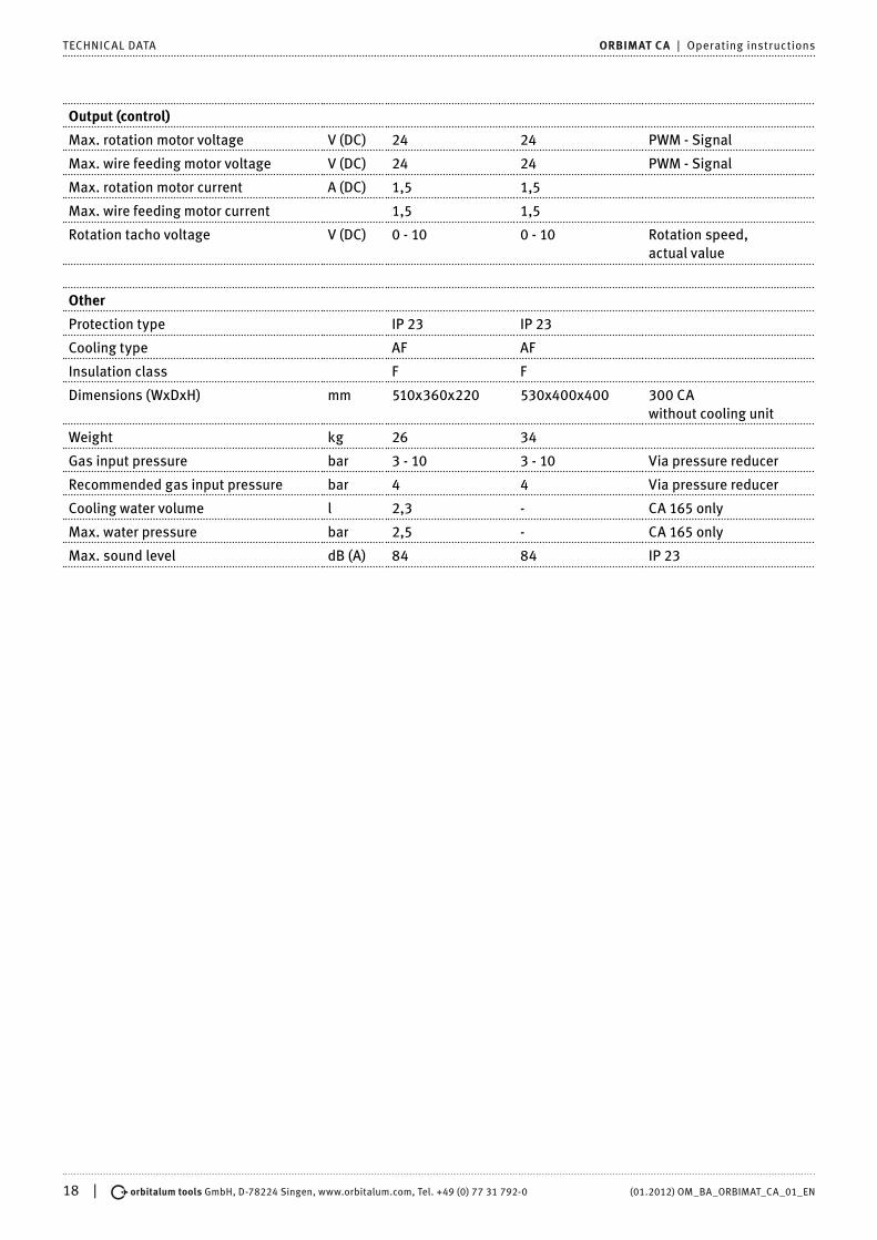
Other
Protection type IP 23 IP 23
Cooling type AF AF
Insulation class F F
Dimensions (WxDxH) mm 510x360x220 530x400x400 300 CA without cooling unit
Weight kg 26 34
Gas input pressure bar 3 - 10 3 - 10 Via pressure reducer
Recommended gas input pressure bar 4 4 Via pressure reducer
Cooling water volume l 2,3 - CA 165 only
Max. water pressure bar 2,5 - CA 165 only
Max. sound level dB (A) 84 84 IP 23

(01.2012) OM_BA_ORBIMAT_CA_01_EN orbitalum tools GmbH, D-78224 Singen, www.orbitalum.com, Tel. +49 (0) 77 31 792-0 | 19
ORBIMAT CA | Operating instructions COMMISSIONING
6. COMMISSIONING
6.1 Checking scope of delivery• Check delivery for completeness and transport damage.
• Report missing parts or transport damage to the location of purchase immediately.
6.2 Scope of delivery• 1 orbital welding power source of the ORBIMAT CA series
• 1 ORBIMAT hose connection set (875.030.018)
• 1 dummy plug for insertion into the connection of the remote control if no external
• remote control will be used (875.050.006)
• 1 liter of anti-freeze (875.030.011)
• 1 filling funnel (875.030.014)
• 1 external operating keyboard (875.012.075)
• 2 keys for key switch (for subsequent ordering of one key, 875.012.058)
• 1 set of operating instructions

20 | orbitalum tools GmbH, D-78224 Singen, www.orbitalum.com, Tel. +49 (0) 77 31 792-0 (01.2012) OM_BA_ORBIMAT_CA_01_EN
SETUP AND ASSEMBLY ORBIMAT CA | Operating instructions
7. SETUP AND ASSEMBLY
7.1 Control elements
7.1.1 Overview of the main control elements
The main control elements are five push switches, so-called "softkeys" (Items 1–5) with variable functions located on the top of the machine. The current function of these softkeys depends on the respective operating status of the system and is indicated by the display on the bottom line.The included standard PS2 keyboard can be set up before the softkeys.The individual menu items are selected using the rotary knob (Item 6) and confirmed by pressing the rotary knob.Detailed descriptions are provided with the explanation of the respective operating steps.
65432
1
1. Push switch(softkey) 1
2. Push switch(softkey) 2
3. Push switch(softkey) 3
4. Push switch(softkey) 4
5. Push switch(softkey) 5
6. Rotary knob
Fig. 4: Main control elements
7.1.2 Connections and control elements on the front panel
1
23456
7
1. Gas hose2. Water connection,
red (water return)3. Water connection,
blue (water flow)4. Weld current socket5. Weld current plug6. Amphenol socket,
control line7. Strain relief eye
Fig. 5: Front panel: Connections and control elements

(01.2012) OM_BA_ORBIMAT_CA_01_EN orbitalum tools GmbH, D-78224 Singen, www.orbitalum.com, Tel. +49 (0) 77 31 792-0 | 21
ORBIMAT CA | Operating instructions SETUP AND ASSEMBLY
• The connections at Items 1–7 are intended for the connection of the various weld heads from the ORBIMATIC line. The coding prevents plugs from being mixed up. The cooling water connections (water flow and return) are the same.
1
5
6 7
42
3
1. Gas quantity setting2. Connection of BUP
Control Box3. ORB 1001 connection4. Key switch5. Remote control
connection6. STOP indicator
(with EMERGENCY-STOP active)
7. Multicard reader
Fig. 6: Front panel: Connections and control elements
• Remote control connectionConnection for remote control (optional) or dummy plug.If remote control is not being used and the dummy plug is not inserted, most of the system is deenergized. The pilot light in the red main switch lights up, and the STOP indicator for active EMERGENCY-STOP lights up red.
• Key switchThe key switch disables procedure modification.A shortened selection menu (main menu) appears if procedure modification is disabled.Key position (as shown): Modification enabled In the "disabled" key position, the key can be removed.
• ORB 1001 connectionConnection of a residual oxygen meter (type ORB 1001) (optional).For continuous monitoring of the forming gas: The portion of residual oxygen remains below a percental portion which can be set at the device (e.g. 70 ppm).
• Connection of BUP Control BoxFor supplementary devices for control of the forming gas pressure (BUP: BackUp Pressure Control) (optional).These supplementary devices record the gas pressure inside the pipe using a pressure sensor and change it using a controllable gas valve.
• Multicard readerFor the exchange of procedures between multiple machines, for the creation of backup copies of the system data and for updating the system, languages, header data and the database for auto programming.Memory cards which can be used: CF, SD, MMC, Smart Media and Sony Memory Stick
• Gas quantity setting (weld gas)Adjusting screw with sight glass for setting the weld gas quantity.
• Other connection options (on device rear)Optionally, the connection of an external keyboard (included in the scope of delivery) or an external printer and/or monitor to the rear of the device is possible.
7.1.3 Operating concept
The main control elements are the rotary knob and five push switches. The current function assignment of theseswitches is displayed in the fields at the bottom edge of the display. Direct access to standard functions (e.g. "start" and "stop") is possible at all times.

22 | orbitalum tools GmbH, D-78224 Singen, www.orbitalum.com, Tel. +49 (0) 77 31 792-0 (01.2012) OM_BA_ORBIMAT_CA_01_EN
SETUP AND ASSEMBLY ORBIMAT CA | Operating instructions
Optional text entry is possible using an external keyboard. If faults occur (e.g. failure of the rotary knob or softkeys), the machine can be operated completely using the external keyboard.
7.1.4 Operation via the rotary knob
The rotary knob has either a fine or rough detent when being turned, depending on whether you are navigating bet-ween menu items/fields (rough detent) or setting parameter values (e.g. weld current) (fine detent).
Navigating to a menu item/field in the display X Turn rotary knob. The menu item/field appears in blue.
Selecting menu item/field X Briefly press the rotary knob. The menu item is selected.
Exiting menu and navigating to the next-higher menu level X Press the rotary knob for more than 2 seconds. The menu of the next-higher level appears in the display.
Setting a parameter/Entering a value X Highlight a field. The field appears in red. X Change value within the specified limit values: Turn rotary knob. X Save value and exit field: Briefly press the rotary knob.
7.1.5 Operation via push switches (softkeys)
The five push switches are assigned with standard functions as softkeys.
Examples
The push switch (Item 5) is usually assigned the "Menu" function, i.e. pressing it brings you directly to the main menu, regardless of which sub-menu currently appears in the display.
The push switch (Item 3) is assigned the "Save procedure" function. It can be used to quickly save a procedure change.
7.1.6 Operation via an external keyboard
Navigating to a menu item/field in the display X Press UP and DOWN arrow buttons.
Selecting menu item/field X Press ENTER key.
Setting a parameter/Entering a value X Highlight a field. The field appears in red. X Enter value: Change with the arrow buttons or enter directly with the number buttons. X Save value and exit field: Press ENTER key.
Entering comments on procedures X Select a comment field. X Enter text using the keyboard.
Using push switches (softkeys) on the keyboard
Function keys F1 through F5 on the external keyboard correspond to push switches 1 through 5.

(01.2012) OM_BA_ORBIMAT_CA_01_EN orbitalum tools GmbH, D-78224 Singen, www.orbitalum.com, Tel. +49 (0) 77 31 792-0 | 23
ORBIMAT CA | Operating instructions SETUP AND ASSEMBLY
7.2 Connection of the power source
7.2.1 Connecting gas bottle and weld head
DANGER
Electrical hazards through touching and incorrect or damp safety equipment.Electric shock!
[ Do not touch energized parts (pipe), especially when igniting the arc. [ Do not allow persons with increased sensitivity to electrical hazards
(e.g. weakness of the heart) to work with the system. X Wear dry safety shoes, dry metal-free (grommet-free) leather gloves and dry safety suits. X Work on a dry surface.
WARNING
Ultraviolet radiation from the arc while welding.Damage to eyes and burning of skin!
X During operation wear eye protection as per EN 170 and skin-covering safety clothing. X With closed weld heads, ensure proper working order of the eye protection.
WARNING
Falling objects or tipping and snapping pipes.Irreversible crushing!
X Place sufficient supports under pipe.
WARNING
Uncontrollable pipe movement.Danger of crushing!
X Secure pipe and weld head so that they are stable.
Setting up machine X First set up system for connection in such a way that it is as accessible as possible from the front and back. X Ensure that the machine is disconnected from the mains network on all sides. X Secure machine against being switched on accidentally.
Connecting a gas bottle X Check stability of the gas bottle. Secure gas bottle against falling over. X Ensure that the union nut on the pressure reducer fits the thread on the valve of the gas bottle. X Mount pressure reducer on the gas bottle. X Connect gas sparger. (There is no gas sparger if a double pressure reducer is used). X Screw both included gas hoses onto the gas sparger or the double pressure reducer. X Insert gas hose (which is intended for connection to the power source and is identified by the plug-in nipple made
of brass on the end) into the intended connection socket on the back of the power source. X Connect weld head.
Connecting weld head
CAUTION
Disconnection of the control plug and breakage of the connected control cable due to improper handling.Damage to control cable!
[ Do not turn the rear screw joint of the control plug strain relief. X When tightening and loosening, ensure that only the front, loose union nut is turned.
CAUTION
Fault during ignition and current transfer, overheating due to loose weld current plug. Damage to the plugs, and machine failure!
X Replace loose, non-firmly fitting weld current plug.
X Hook carabiner of the hose assembly for strain relief into the strain relief eye (Fig. 5, Item 7). X Insert 24-pin control plug of the weld head into the control line (Fig. 5, Item 6). X Insert the two weld current plugs for the ground connection (Fig. 5, Item 5) and the electrode
connection (Fig. 5, Item 4). X Ensure that both plugs are inserted fully and are firmly seated.

24 | orbitalum tools GmbH, D-78224 Singen, www.orbitalum.com, Tel. +49 (0) 77 31 792-0 (01.2012) OM_BA_ORBIMAT_CA_01_EN
SETUP AND ASSEMBLY ORBIMAT CA | Operating instructions
X Connect water hoses to the quick-action closures (Fig. 5, Items 3 and 2). The direction of flow of the cooling water is not important here. Ensure that they engage properly and are free of kinks.
X Insert gas hose with plug-in nipple into gas hose connection (Fig. 5, Item 1).
A dummy plug (Item 5) must be inserted into the remote control connection if remote control will not be used (standard scope of delivery). The system may only be operated if either the dummy plug is inserted or a remote control is connected.
X Insert a dummy plug into the remote control connection (Item 5) if necessary.
Properly connected weld head:
Fig. 7: Weld head, connected
Detaching water hoses X Lightly push back front ring on machine-side connection and pull off water hose.
Pumping out waterThe connections of the machine close automatically when the cooling water is removed.
X When connecting the water hoses, pay attention to the flow and return. X Connect drain hose to the water connection, blue (Fig. 5, Item 3). X Close off the water hoses with the included plugs to prevent the cooling water from running out of the weld head.
Closing off gas hose X Actuate the side pawl on the hose-side plug connection and pull gas hose out of connection.
7.3 Commissioning
WARNING
Ultraviolet radiation from the arc while welding. Damage to eyes and burning of skin!
X During operation, wear eye protection as per EN 170 and skin-covering safety clothing. X With closed weld heads, ensure proper working order of the eye protection.
WARNING
Hot leaking liquids and hot plug connections during heavy operation.Danger of scalding!
X Heed the safety precautions of the technical supervisor/person in charge of safety.
CAUTION
Hot surfaces of the weld head and weld points, including for a period of time after welding.Danger of burns!
X Wear safety gloves.

(01.2012) OM_BA_ORBIMAT_CA_01_EN orbitalum tools GmbH, D-78224 Singen, www.orbitalum.com, Tel. +49 (0) 77 31 792-0 | 25
ORBIMAT CA | Operating instructions SETUP AND ASSEMBLY
DANGER
Faulty ignition in case of unmounted or incorrectly positioned weld head.Electric shock, bodily injury and damage to property at other devices aswell!
X If the weld head is not ready for operation, switch machine to the "Test" function.
DANGER
Improper access to and opening of the ORBIMAT system.Electric shock!
X Disconnect system from mains. X Disconnect all external devices connected to the system (weld heads etc.). X If the machine was just in operation, allow it to cool down sufficiently. X Allow only a professional electrician to access the electrical system. [ Never connect an opened system to the mains network.
DANGER
Liquid in the housing due to improper use and transport.Electric shock!
[ Do not place liquids (drinks) on the system. X Do not block ventilation slots. X Check housing interior for moisture after transporting the machine and leave it open
to air it out if necessary.
7.3.1 Adding anti-freeze and water
Before welding may be carried out, the cooling water circuit is filled anti-freeze and water.It is not possible to use the Orbicool 3004 and another external cooling system simultaneously.
X XXEnsure that the machine is not connected to the mains network during filling. X XXSecure machine against being switched on accidentally.
ORBIMAT 165 CA:1. Open tank closure on the top of the device.2. Add all the included anti-freeze to the tank with a suitable funnel.3. Fill tank up to the "MAX" mark (visible behind the left side panel) with tap water.
Carefully wipe off any spilled water from the machine.4. Close tank with screw cap.
ORBIMAT 300 CA (Orbicool 3004):1. Open screw cap of the water tank located on the side.2. Add all the included anti-freeze to the tank with a suitable funnel.3. Fill tank up to the "MAX" mark (visible in sight glass on front of cooling unit) with tap water.
Carefully wipe off any spilled water from the machine.4. Close tank with screw cap.
7.3.2 Commissioning water pump
A low-maintenance and low-wear water pump (magnetic coupling without vulnerable mechanical seal, brushless DC motor) is installed in the OM 165 CA und OM 300 CA units. The water pump is not self-priming and must be filled with water once before operation.
Connecting water hoses1. Connect included water hose to the blue connection of the unit.2. Ensure that the exiting water is caught by a container (e.g. empty bottle).
Switching on machine1. Connect machine to the mains network.2. Switch on machine at the main switch.The software is loaded. The main menu (long form) appears in the display.3. If the main menu appears in short form: Set front key switch to "disabled" position.
Problems while switching on

26 | orbitalum tools GmbH, D-78224 Singen, www.orbitalum.com, Tel. +49 (0) 77 31 792-0 (01.2012) OM_BA_ORBIMAT_CA_01_EN
SETUP AND ASSEMBLY ORBIMAT CA | Operating instructions
Is the machine not starting the first time it is switched on? X Check whether the pilot light in the main switch is lit up.
Is the pilot light not lit up?There is a problem with the power supply (no voltage, plug not inserted).
X Check whether the power plug is properly inserted. X Have the power supply checked.
Is the pilot light lit up? X Check whether the STOP indicator (for active EMERGENCY-STOP) on the front panel is lit up.
Is the STOP indicator on the front panel lit up?With external remote control connected: EMERGENCY-STOP switch is pressed.1. Unlock EMERGENCY-STOP switch by turning it counterclockwise.2. Switch off machine.3. Wait at least 5 seconds and then switch machine on again.Is an external remote control not connected?The dummy plug is missing from the remote control connection, EMERGENCY-STOP is activated.
X Insert dummy plug to close the EMERGENCY-STOP circuit if necessary.
Pumping out waterTo protect the pump against possible dry running, the software stops pumping out after approx. 30 seconds.
Fig. 8: Main menu (long form)
1. In the main menu, call up the "System settings" menu item by turning the rotary knob.2. Briefly press rotary knob.The System settings sub-menu appears.
(01.2012) OM_BA_ORBIMAT_CA_01_EN orbitalum tools GmbH, D-78224 Singen, www.orbitalum.com, Tel. +49 (0) 77 31 792-0 | 27
ORBIMAT CA | Operating instructions SETUP AND ASSEMBLY
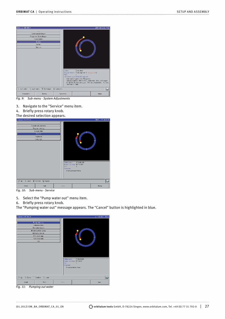
Fig. 9: Sub-menu - System Adjustments
3. Navigate to the "Service" menu item.4. Briefly press rotary knob.The desired selection appears.
Fig. 10: Sub-menu - Service
5. Select the "Pump water out" menu item.6. Briefly press rotary knob.The "Pumping water out" message appears. The "Cancel" button is highlighted in blue.
Fig. 11: Pumping out water

28 | orbitalum tools GmbH, D-78224 Singen, www.orbitalum.com, Tel. +49 (0) 77 31 792-0 (01.2012) OM_BA_ORBIMAT_CA_01_EN
SETUP AND ASSEMBLY ORBIMAT CA | Operating instructions
7. Allow water pump to run until the water exits the drain hose under pressure.8. Confirm "Cancel" by briefly pressing the rotary knob.The water pump is switched off. The water pump is now filled with water and is ready for operation.
If the water does not exit the hose within a maximum of 10 seconds:1. Cancel drainage, as prolonged dry running can damage the pump.2. Check water level.3. Check whether the pump is running and if a pumping sound can be heard.Additional help see Sec. 9, Page 59 "Service and troubleshooting".

(01.2012) OM_BA_ORBIMAT_CA_01_EN orbitalum tools GmbH, D-78224 Singen, www.orbitalum.com, Tel. +49 (0) 77 31 792-0 | 29
ORBIMAT CA | Operating instructions OPERATION
8. OPERATION
8.1 Auto programming
8.1.1 Setting parameters
1. Connect weld head.2. Switch on machine.The main menu appears in the display (Fig. 8 "Long form").3. Switch over to the view of the long menu if necessary.4. Select and highlight the "Auto programming" menu item.The following display appears:
Field "....": Return to main menuFields ("Weld head model" to "Wall thickness"): Parameter entryField "Wire feed": Welding with/without filler wire."Calculate procedure": Calculation of the procedure with the entered parameters.
Fig. 12: Sub menu - Auto programming
Configuring weld head1. Select "Weld head" field and briefly press the rotary knob.The following display appears:
A list of the weld heads which can be used with this system appears.This system automatically detects the type of connected head and offers it for selection first. In the example, this is an OW 115.
Fig. 13: Selecting a weld head
2. Select desired weld head by turning the rotary knob. – or – Select the weld head highlighted by the system.
3. Confirm by briefly pressing the rotary knob.
Configuring material1. Select "Material" field and briefly press the rotary knob.The following display appears:

30 | orbitalum tools GmbH, D-78224 Singen, www.orbitalum.com, Tel. +49 (0) 77 31 792-0 (01.2012) OM_BA_ORBIMAT_CA_01_EN
OPERATION ORBIMAT CA | Operating instructions
Materials in the list:
• Chrome-nickel-steels: Five materials
• Ferritic materials: Two materials
• Titanium (Ti)
Fig. 14: Selecting material
Does the material used not appear in the list? X Select the most similar material (example: for stainless steels, one of the chrome-nickel-steels).
2. Select material.3. Confirm by briefly pressing the rotary knob.
Configuring protective gas1. Select "Gas type" field and briefly press the rotary knob.2. Select protective gas.3. Confirm by briefly pressing the rotary knob.
Configuring pipe diameter1. Select "Diameter" field.The following display appears:
Fig. 15: Pipe diameter setting
2. Select value by pressing the rotary knob.3. Enter values via the external keyboard or the rotary knob.The value range is automatically limited to the possible diameter range of the connected or previously selected weld head here.
Configuring wall thickness1. Select "Wall thickness" field and briefly press the rotary knob.The value range is limited to 4 mm.

(01.2012) OM_BA_ORBIMAT_CA_01_EN orbitalum tools GmbH, D-78224 Singen, www.orbitalum.com, Tel. +49 (0) 77 31 792-0 | 31
ORBIMAT CA | Operating instructions OPERATION
We recommend a so-called "tulip-shaped" or "U-shaped" preparation for these wall thicknesses (approx. 4 mm and larger).In these cases, we recommend carrying your own weld tests. Auto programming can be helpful here, because you can enter the thickness of the bluntly-joined root face (usually 1.5–2.5 mm) as the wall thickness first, and then manually improve the auto programmed procedure calculated in this way.
2. Select value by pressing the rotary knob.3. Enter values via the external keyboard or the rotary knob.
Configuring wire feedSelection is only possible if the connected weld head is capable of cold wire feeding.If cold wire feeding is not possible, the option fields are given a gray background, "No" is configured and this cannot be changed by the operator (see also Fig. 15).1. Select "Wire feed" field and briefly press the rotary knob.2. Select "Yes" option (with wire feed) and "No" option (without wire feed).
Calculating procedure1. Select and briefly press the "Calculate procedure" menu item.The procedure is calculated. The main menu appears in the display.
8.2 Testing the procedure
8.2.1 Preparing weld head
Naturally, these operating instructions can only provide basic information on the most commonly used weld heads (due to the variety of tools which can be connected).In the following, the important actions for so-called "open" weld tongs and cassette heads are listed.
X Refer to detailed information on preparing the operating instructions of the weld head.
D Gas bottle and weld head connected see Sec. 7.2.1, Page 23.
D Commissioning carried out see Sec. 7.3, Page 24.
D Machine switched on.
Preparing electrodeFor almost all ORBIMATIC weld heads: Electrodes with a diameter of 1.6 mm and 2.4 mm can be used.
X For "Micro head" type OW 12: Use only electrodes with a 1.0 mm diameter. X Up to a current of approx. 100 amperes (high-pulse): Use electrodes with a 1.6 mm diameter (recommendation). X Calculate electrode diameter based on the max. weld current of the application.
If smaller currents are used, the use of 2.4 mm electrodes can lead to a worsening of the ignition characteristics and "wandering" of the arc at the electrode.
WARNING
Sharply ground and pointy electrodes!Danger of injury.
X Store ground electrodes so that there is no danger of injury.
Turning weld headYou can turn the weld heads with a motor for insertion of the electrode.

32 | orbitalum tools GmbH, D-78224 Singen, www.orbitalum.com, Tel. +49 (0) 77 31 792-0 (01.2012) OM_BA_ORBIMAT_CA_01_EN
OPERATION ORBIMAT CA | Operating instructions
CAUTION
Unintended starting of the welding procedure!Danger of injury. Damage to materials and machine.In the "ready to start" condition (see Fig. 16), the "Start" button could be pressed by an unauthorized person and start the welding procedure.XXAfter inserting the electrode, ensure that the "Start" button in the display is not lit red.XXOnly use the function for motor movement from the "red" start area if the weld head is being moved immediately before starting the process, e.g. to change the starting position.
"Test mode" is indicated by the "Start" button lit yellow.The start command in test mode starts running a procedure without igniting an arc and therefore without weld current; the gas valve and water pump are switched off. You can use this "dry run" to check the change in level at the intended points on the pipe and the run of the motor.
Fig. 16: Machine ready to start - Welding (left) Fig. 17: Machine ready to start - Test run (right) - Start
• With the remote control of the weld head: X Press gray "Motor" button until the desired position is reached. Only one rotation direction is possible here.
• With an additional remote control (optional, available as accessory): X Press "MOTOR+" or "MOTOR–" button.
The rotor turns in the selected direction as long as a button is being pressed.• With the push switches of the machine:
X Call up main menu if necessary. X Press softkey 2 "Test".
The main menu in test mode appears in the display, and the "Start" button is yellow. X Press softkey 4 "Motor".
The assignment of the softkeys for controlling the motor changes. X Press "Motor forward" or "Motor backward" button.
The motor runs in the selected direction as long as a button is being pressed. X Press softkey 2 "Home".
The weld head turns to the open position. X Press softkey "Motor OK" to exit the operating diagram. X Press softkey 5 "Menu" to change directly to the main menu.
8.2.2 Connecting forming gas
With orbital welding, sufficient gas coverage must also be ensured inside the pipe ("root protection") with an inert gas (usually argon). This also applies for the so-called "black" (ferritic) materials.
X Plug up lines of the gas bottle with suitable stoppers. X Open regulator on gas bottle and set a low flow rate for forming gas. X Ensure sufficient gas pre purge time before starting the machine.
To determine the right time, the residual oxygen meter (ORB 1001) can be used.

(01.2012) OM_BA_ORBIMAT_CA_01_EN orbitalum tools GmbH, D-78224 Singen, www.orbitalum.com, Tel. +49 (0) 77 31 792-0 | 33
ORBIMAT CA | Operating instructions OPERATION
CAUTIONImpermissible gas pressure inside the pipe. Penetration of melted metal into the weld head.Damage to weld head.
[ Ensure that gas pressure does not build up inside the pipe.
X XWhen using closed weld heads, ensure that the same gas type is used both outside and inside the pipe, i.e. the same gas both for the machine (weld head) and that which is fed into the pipe.
Different gas types can lead to an undefined mixture of both gases in the welding pocket and thus to uneven weld penetration.
X Do not use "classic" forming gases with up to 30% hydrogen content.A small amount of hydrogen which ends up in the welding pocket from inside the pipe via the pipe joint can lead to considerably greater penetration, as the hydrogen releases additional energy during combustion.Values gained from experience: An admixture of only 2% hydrogen has roughly the same effect on penetration as a 10% increase in weld current.
8.2.3 Welding
Starting the welding process X Before beginning, read "Interrupting the welding process" see Sec. 8.2.4, Page 34 so that you can take action
immediately in case irregularities arise during a test run.
D Power source programmed
D Weld heads prepared for welding: Properly connected and positioned
D Gas bottle secured and opened
D Machine switched on
D The main menu appears in the display
X Press softkey 1 "Weld".The machine is ready to start. The "Start" button in the display is red.
X Press softkey 1 "Start".– or –
X Press START button on an external remote control, if connected.– or –
X Press red START/STOP button on weld head.The water pump starts up, and the solenoid valve is opened. After the programmed gas pre-flow time passes, the arc is ignited and the welding process begins.The machine carries out the welding process completely.Open the gas bottle and regulate to a small flow of forming gas mixture.
X Observe welding process continuously and be prepared to take action at any time. X With open weld tongs: Ensure proper guidance of the hose assembly while the rotor is
circling.Possible problems with the welding process:
• Incorrectly set weld current
• LP weld tong not tensioned tightly enough
• Forming gas quantity too high, holes being formed X In these cases, interrupt welding process see Sec. 8.2.4, Page 34.
Welding process – SequenceThe machine carries out the welding process completely. During the welding process, the machine monitors the welding process and the following parameters:
• Cooling water flow: The welding process is stopped if the limit value of 0.8 L/min is undershot.
• Gas flow: The welding process is interrupted if 3 L/min is undershot.
• The weld current, weld voltage and weld speed process parameters:

34 | orbitalum tools GmbH, D-78224 Singen, www.orbitalum.com, Tel. +49 (0) 77 31 792-0 (01.2012) OM_BA_ORBIMAT_CA_01_EN
OPERATION ORBIMAT CA | Operating instructions
Limit values specified in the program are taken into account.
Fig. 18 Display during runing welding process
Progress of process: Bar graph with specifications of process progress (in %) for the respective current sectorCorrection factor: Percent value by which the current in the current process was changed in comparison to thesaved procedureParameters Diameter to Wire LP Speed: Display of the process parameter of the procedure. The values can be changed during the welding process. The changes are saved to the current welding process by pressing the rotary knob (key-board: ENTER). The changes are not yet saved in the procedure. Fields with a gray background cannot be edited.Graphic: Display of the weld sequence. After starting up, a pointer pointing to the inner yellow dot appears during gas pre purge. After the gas pre purge, pool formation occurs (the time after ignition during which no rotational movements are occurring for buildup of the weld pool). In the individual sectors, the respective current sector is highlighted in white, and the accompanying red indicator indicates the current electrode position. The current sector number and current position (in angular degrees) appear in the bottom section of the graphic.Info field: The following information appears in the info field (below the graphic): Name of the folder in which the proce-dure is saved, name of the running procedure, current measurement values for water flow (in L/min), water temperature and inverter temperature (in °C); current mains voltage (in V).Warning messages and error messages appear in the "Warning" field.
The info field only appears during a running welding process.
Other: The following information appears on the two bottom lines: Help texts for operation with the rotary knob; on the right, information on the activated printer and the memory card (diskette symbol). When the printer is activated (e.g. log printing after welding) or the card is activated (procedure being loaded), the symbols are highlighted in red.Softkeys: The current assignment of the softkeys appears at the bottom edge of the display. During the welding pro-cess, only softkeys 1 and 2 ("Stop" and "Final slope") are active.
Ending the welding processThe following steps are carried out automatically at the end of the welding process:
• Current is automatically sloped off to the programmed final current.
• The arc is extinguished.
• Gas flow and water cooling are deactivated after the programmed time expires.
• Machine switches to ready-to-start condition.
8.2.4 Interrupting the welding process
Switching off entire system X XXSwitch off machine at the main switch.
– or –

(01.2012) OM_BA_ORBIMAT_CA_01_EN orbitalum tools GmbH, D-78224 Singen, www.orbitalum.com, Tel. +49 (0) 77 31 792-0 | 35
ORBIMAT CA | Operating instructions OPERATION
X Press EMERGENCY-STOP button on connected remote control.The entire machine is disconnected from the mains network immediately and completely (both poles). No other functions are carried out here: The gas flow is interrupted immediately. The current weld becomes unusable.
Stopping a running process X Press softkey 1 ("Stop").
– or – X Press STOP button on connected remote control.
– or – X Press red START/STOP button on weld head.
The weld current is switched off immediately. The machine remains in operation, the gas post purge time runs and the water cooling of the weld head is carried out until the end of the gas post purge time.A slight crater can arise in the seam on the workpiece, and this can be compensated for by over-welding it.
Premature slope-off of a running process X Press softkey 2 ("Final slope").
– or – X Press the "Final" button on the weld head.
– or – X Press slope-off symbol on connected remote control.
The machine slopes off the weld current as per the procedure. The weld head continues running during the slope-off phase. After slope-off, the weld current is switched off, the gas post purge and pump continue running until the end of the programmed time.
8.3 Adjusting the procedure
8.3.1 Reasons and steps for adjusting procedure
The auto programming of the machine cannot take all influencing factors into account during welding. Procedures can be adjusted after the test run for this reason. Possible reasons:
• Batch-dependent fluctuations in the material composition
• Different dissipation (pipe on solid parts) etc.
X Improve procedure step by step. When adjusting, change only one parameter at a time so that you can better judge the influence on welding.
X Save adjusted procedure. X After the adjustment, carry out a test run of the parameters. X Observe effects of the adjustment and carry out further adjustments if necessary.
8.3.2 Making percental changes
Reason: Welding result even, but weld seam penetrated too lightly or too heavily.The percental change affects all levels (sectors) on high- and low-pulse current.After the test run, the "Correction factor" field is highlighted in the display.1. Highlight a field.2. Adjust and save value with rotary knob or keyboard:
Positive value: Increase weld current Negative value: Reduce weld current
The settable value range can be limited in the program (e.g. only max. +5% and min. –5%). X Turn key switch to cancel limit if necessary.
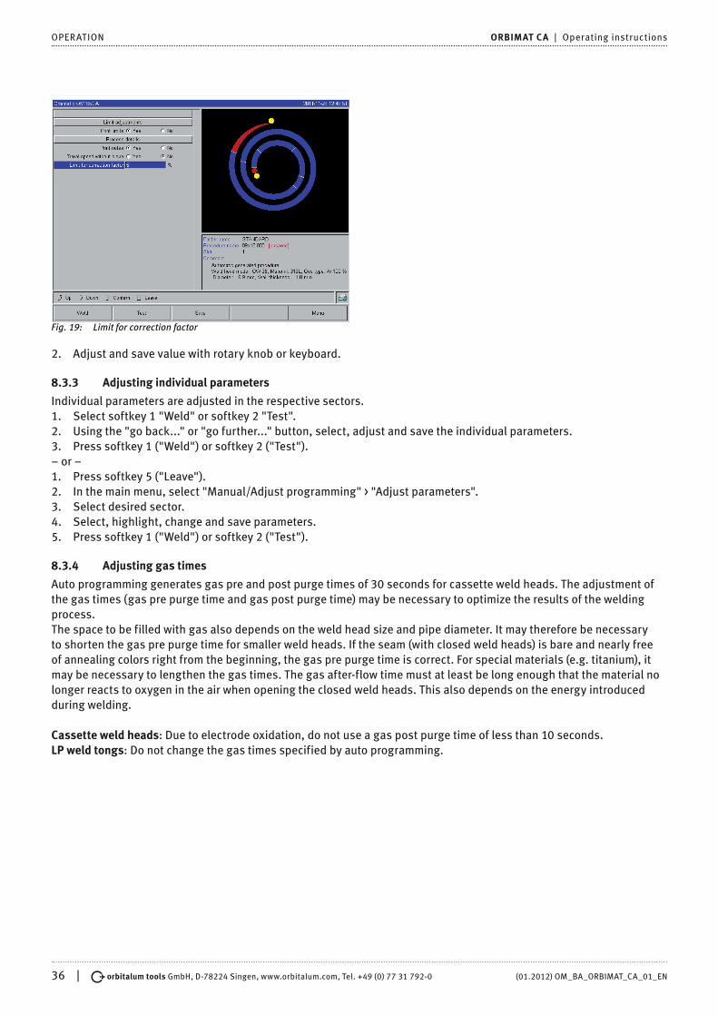
Changing correction factor limit1. In the main menu, select "System settings" > "Program settings".The current limit is specified in the "Limit for correction factor" field, in which the operator can change the correction factor in "completed" mode (production mode).
Example: Specification "5%" – Change in range from –5% to +5% (absolute range: 10%).
36 | orbitalum tools GmbH, D-78224 Singen, www.orbitalum.com, Tel. +49 (0) 77 31 792-0 (01.2012) OM_BA_ORBIMAT_CA_01_EN
OPERATION ORBIMAT CA | Operating instructions
Fig. 19: Limit for correction factor
2. Adjust and save value with rotary knob or keyboard.
8.3.3 Adjusting individual parameters
Individual parameters are adjusted in the respective sectors.1. Select softkey 1 "Weld" or softkey 2 "Test".2. Using the "go back..." or "go further..." button, select, adjust and save the individual parameters.3. Press softkey 1 ("Weld") or softkey 2 ("Test").– or –1. Press softkey 5 ("Leave").2. In the main menu, select "Manual/Adjust programming" > "Adjust parameters".3. Select desired sector.4. Select, highlight, change and save parameters.5. Press softkey 1 ("Weld") or softkey 2 ("Test").
8.3.4 Adjusting gas times
Auto programming generates gas pre and post purge times of 30 seconds for cassette weld heads. The adjustment of the gas times (gas pre purge time and gas post purge time) may be necessary to optimize the results of the welding process.The space to be filled with gas also depends on the weld head size and pipe diameter. It may therefore be necessary to shorten the gas pre purge time for smaller weld heads. If the seam (with closed weld heads) is bare and nearly free of annealing colors right from the beginning, the gas pre purge time is correct. For special materials (e.g. titanium), it may be necessary to lengthen the gas times. The gas after-flow time must at least be long enough that the material no longer reacts to oxygen in the air when opening the closed weld heads. This also depends on the energy introduced during welding.
Cassette weld heads: Due to electrode oxidation, do not use a gas post purge time of less than 10 seconds.LP weld tongs: Do not change the gas times specified by auto programming.

(01.2012) OM_BA_ORBIMAT_CA_01_EN orbitalum tools GmbH, D-78224 Singen, www.orbitalum.com, Tel. +49 (0) 77 31 792-0 | 37
ORBIMAT CA | Operating instructions OPERATION
Fig. 20: Input field - Gas post purge time
1. Press softkey 1 "Weld".2. Using the "go back to gas post purge time" or "go further to gas pre purge time" button, select, adjust and save the
individual parameters.– or –1. In the main menu, select "Manual/Adjust programming" > "Adjust parameters".2. Select, highlight, adjust and save parameters.
X Press softkey 1 ("Weld") or softkey 2 ("Test").The machine is ready to start.
8.3.5 Adjusting ignition current, end current and current slope-off
X Adjust values specified by auto programming only in exceptional cases (e.g. with extremely thin-walled pipes).Ignition current: Value specified during ignition. The ignition current is active only very briefly and affects the ignition behavior itself. If the ignited arc is detected, the machine switches to the current programmed on level 1 within a few tenths of a second.Final current: Current level reached by the final slope-off immediately before switch-off of the arc at the end of the wel-ding process. The value must be greater than 0. Otherwise, the arc will cut out before the end of the welding process.
X Ensure that the value (3 A) is not zero.For extremely large arc gaps (LP tongs):
X If the arc cuts out at the end of current slope-off: Increase value.
Slope-off time: Time from the end of the last-used weld sector to the switch-off of the arc. This is identified by an incre-asingly narrower weld seam on the welded part.The current slope-off is necessary to prevent a final crater (formed due to immediate switch-off) from being formed.Is a longer or shorter run-out of the weld seam desired?
X Increase or decrease value.

38 | orbitalum tools GmbH, D-78224 Singen, www.orbitalum.com, Tel. +49 (0) 77 31 792-0 (01.2012) OM_BA_ORBIMAT_CA_01_EN
OPERATION ORBIMAT CA | Operating instructions
Fig. 21: Input field - Ignition current and pool formation time
1. Ignition current: Using the "go further to gas pre purge time" > "go further to start delay time" buttons, select, adjust and save parameters.
2. Final current and current slope-off: Using the "go further to gas post purge time" > "go back to weld seam end" buttons, select, adjust and save parameters.
3. Press softkey 1 ("Weld") or softkey 2 ("Test").– or –1. In the main menu, select "Manual/Adjust programming" > "Adjust parameters".2. Select, highlight, adjust and save parameters.3. Press softkey 1 ("Weld") or softkey 2 ("Test").The machine is ready to start.
8.3.6 Adjusting the pool formation time
Pool formation time: Start delay of the rotation motor so that a point weld penetration exists at the beginning of the rotation movement. The pool formation time must be adjusted if the starting point shows too much or too little weld penetration. Adjustment of the pool formation time is made easier by observing, for example, the root formation inside the pipe on a test piece. Ideally, the rotation should begin immediately after a visible formation of the melt pool inside the pipe.Increasing the weld current in the 1st sector affects the energy introduced to the melt pool during pool formation.
X Ensure that the weld current of the 1st sector is used during pool formation.1. Using the "go further to gas pre purge time" > "go further to start delay time" buttons, select, adjust and save
parameters.– or –1. In the main menu, select "Manual/Adjust programming" > "Adjust parameters".2. Select, highlight, adjust and save parameters.3. Press softkey 1 ("Weld") or softkey 2 ("Test").The machine is ready to start.
8.3.7 Adjusting welding current and transition times ("Slope")
The weld currents in the individual sectors are the process parameters which are changed most often in practice to achieve optimum and even weld seam formation. If the seam is welded unevenly or insufficiently, adjust the energy being applied.To prevent changes in voltage from being sudden, and thus a possible visible change in the seam, a value can be speci-fied for a transition time starting with sector 2. The value is a percental value of the sector time in which a linear current transition from (current) value of the previous sector follows the current value of the current sector.
Example
• Current of 50 A (HP) in sector 1 and 45 A (HP) in sector 2
• Sector time in level 2 of 10 sec.
• Slope of 10%

(01.2012) OM_BA_ORBIMAT_CA_01_EN orbitalum tools GmbH, D-78224 Singen, www.orbitalum.com, Tel. +49 (0) 77 31 792-0 | 39
ORBIMAT CA | Operating instructions OPERATION
Process sequence
• The sector is welded up to the end with 50 A (HP or LP as programmed).
• Within 10% of the sector time (i.e. 10% of 10 sec = 1 sec), the current is dropped linearly from 50 A to 45 A.
• For the remaining sector time in sector 2 (9 sec), the current remains constant at 45 A.
Auto programming uses these linear transitions. This reduces the number of sectors. The effects to be compensated for by a change in current (e.g. heating of the pipes during welding) do not have a sudden character and can be compensa-ted for better using transitions.
Alternatively, it is also possible by adjusting the weld speed. With different weld speeds, however, the seam appearance changes ("scaling") if the high- and low-pulse times are not adjusted in the same proportion.
Recommendation for standard applications X The procedure of a constant weld speed within a program "recommended" by auto programming is retained. X To achieve an even seam with proper weld penetration, adjust the current setting in the individual sectors.
For minor adjustments: X Change only the high-pulse current.
– or – X Change both currents in the same direction to obtain the desired "pulse effect".
1. In the main menu, select "Manual/Adjust programming" > "Adjust parameters".2. Select desired sector.The respective selected sector is highlighted in color to the right in the display. The angular degree of this sector is specified.3. Select, highlight, adjust and save the "HP current", LP current" and "Slope" parameters.4. Press softkey 1 ("Weld") or softkey 2 ("Test").The machine is ready to start.
The specification of the current transition in percent is then problematic under certain circumstances if programs from other machines must be transferred with an incompatible data format and these machines are programmed with a slope in seconds instead of percent.The field for input of the slope time can be switched from percent to seconds.See also "Special keyboard commands" see Sec. 8.17, Page 57.
X To switch the slope time specification from % to sec (and vice versa), press the "S", "L" and "O" keys (for SLOPE) on the external keyboard.
X Confirm message (see Fig. 22) by pressing the rotary knob.The next time the machine is started, the % values corresponding to the seconds appear.

40 | orbitalum tools GmbH, D-78224 Singen, www.orbitalum.com, Tel. +49 (0) 77 31 792-0 (01.2012) OM_BA_ORBIMAT_CA_01_EN
OPERATION ORBIMAT CA | Operating instructions
Fig. 22: Converting the slope time from percent to seconds
8.3.8 Adjusting pulse times
Pulse times in most applications: 0.05 to 0.5 seconds.Auto programming calculates the pulse times from the wall thickness. Adjusting the pulse times affects the seam ap-pearance: A shorter pulse time yields a finer scale.
Fig. 23: Input field of a sector with representation of the seam scale
1. In the main menu, select "Manual/Adjust programming" > "Adjust parameters".2. Select desired sector.The respective selected sector is highlighted in color to the right in the display. The angular degree of this sector is specified. An image of the seam scale appears below the process graphic.3. Select, highlight, adjust and save the "HP time" and "LP time" parameters.4. Press softkey 1 ("Weld") or softkey 2 ("Test").The machine is ready to start.
Recommendation [ Do not set the high- and low-pulse times with different values.
Experienced users can adjust the pulse times with different values. This is recommended for certain materials (e.g. copper).
8.3.9 Adjusting weld speed and transition time ("Slope")
Auto programming specifies weld speeds in the range of 70–100 mm/min (at pipe circumference) which lie in the medium range for the TIG process. As of a certain wall thickness, the system drives the motor in sync with the pulse: The motor remains nearly still during the high-pulse phase and moves only during the low-pulse phase.This method reduces the volume of the liquid material so that the melt pool remains under control even with wall thick-

(01.2012) OM_BA_ORBIMAT_CA_01_EN orbitalum tools GmbH, D-78224 Singen, www.orbitalum.com, Tel. +49 (0) 77 31 792-0 | 41
ORBIMAT CA | Operating instructions OPERATION
nesses of around 4.0 mm. In these cases, the average value of both speeds is to be calculated for the resulting speed if the high- and low-pulse times are the same length.
In principle, a high weld speed (up to max. approx. 200 mm/min makes sense) is only possible if the process does not indicate tolerances (offset, wall thickness, air gap etc.).At a somewhat lower speed, irregularities (e.g. minor fluctuations in the pipe wall thicknesses) are tolerated by the process. With auto programming, average values are provided for this reason.If a higher weld speed is required for an application:
X Increase current to introduce the same energy (per section) into the process again.
For different weld speeds in the sectors:When switching between sectors at different speeds, the motor is accelerated or braked linearly if a slope time has been set.
Deactivating transition in the speed1. In the main menu, select "System settings" > "Program settings".2. Select the "No" option for "Speed without ramp".The slope is deactivated in the current procedure.3. Press softkey 5 ("Menu").The machine is ready to start.
If you are working with different speeds in high- and low-pulse current:XXDo not select pulse times shorter than 0.2 seconds to balance the inertia of the motors and the machinery.If the motor is to nearly stand still in the high-pulse phase:XXEnter value "1" for the speed.The motor continues running and does not have to overcome static friction when starting up. This protects the motor and leads to higher precision while complying with the angle of rotation while welding.Auto programming automatically generates the value 1 for the weld speed in the high-pulse time during operation in sync with the pulse.
Adjusting wire feed parameters X Only adjust wire feed parameters if a weld head is connected or was selected with cold wire supply.
With other weld heads, the input fields are grayed-out.
Wire feed parameters:
• Wire start delay (in seconds)
• Wire final delay time (in seconds)
• Wire retract (in seconds)
• Wire HP Speed (in mm/min)
• Wire LP Speed (in mm/min)Changing the wire feed quantity requires a change to the current, since more (cold) material is introduced to the wel-ding process with an increased wire speed, for example. If the wire quantity is too high, it is difficult to control the melt pool in the individual positions or it breaks away or drips off.
Wire start delay: The time from ignition of the arc to the introduction of wire feed. The time corresponds with the time for pool formation (start delay for the rotation motor). It cannot be longer than the pool formation time.In special cases, it can be shorter than the bath formation time, so that the wire enters the melt pool while the rotation motor is still not moving.
X Do not set wire start delay too short, as the wire is not "taken up" if the melt pool has not yet been formed.
Wire final delay time: Time during which the wire is still fed to the process during current slope-off at the end of welding. Its minimum value is 0 and maximum value is as long as the current slope-off. With a value of 0, the wire feed stops when current slope-off begins. If the time corresponds to the duration of the current slope-off, wire continues to

42 | orbitalum tools GmbH, D-78224 Singen, www.orbitalum.com, Tel. +49 (0) 77 31 792-0 (01.2012) OM_BA_ORBIMAT_CA_01_EN
OPERATION ORBIMAT CA | Operating instructions
be fed during the entire slope-off time.Since the introduced energy declines as the current slopes off, the wire feed should stop when there is no longer a melt pool.
Wire retract: Time during which the wire running direction is reversed at the end of the wire feed so that the wire does not rest on the pipe when turning back the weld head. The retraction time should be approx. 1–2 sec. and is set properly when the wire extends 2–3 mm from the feed tube after retraction. If the time is too long, the wire is pulled in completely and the end (which is usually still a liquid ball) can adhere to the wire feed tube.
Wire HP/LP Speed: The wire feed speeds of the filler wire (in mm/min) in the individual sectors. Auto programming usu-ally controls the wire in sync with the pulse: The wire feed motor does not move on the low pulse, as the energy of the arc may not be sufficient to melt the wire under certain circumstances here.To achieve a higher deposition rate:
X Increase speed of the wire in the high-pulse phase.– or –
X Feed wire in the low-pulse phase as well. The weld current set for low pulse must be sufficient here.
1. In the main menu, select "Manual/Adjust programming" > "Adjust parameters" > "Pool formation".2. Select, highlight, adjust and save the "Wire start delay", "Wire final delay time" and "Wire retract" parameters.3. Select "go forward to sector 1" or select the desired sector.
The respective selected sector is highlighted in color to the right in the display. The angular degree of this sector is specified. An image of the seam scale appears below the process graphic.4. Select, highlight, adjust and save the "Wire HP Speed" and "Wire LP Speed" parameters.5. Press softkey 1 ("Weld") or softkey 2 ("Test").The machine is ready to start.
8.3.10 Changing the sector
Auto programming divides welding into different sectors (usually four to six). The parameters can be programmed for each sector. The sector borders can be shifted manually, and sectors can be added or deleted.
Adjusting sector borders with the rotary knob1. In the main menu, select "Manual/Adjust programming" > "Devide into levels".The sector list appears on the left in the display (five sectors in the example, see Fig. 24). The process sequence ap-pears on the right.
Fig. 24: Sector list - Pointer position for 90°
2. Turn rotary knob until the pointer points to a white sector border.The green pointer moves through the sector, and the degree information of the position appears at the bottom edge of the process representation.3. Ensure that the pointer is positioned correctly. For this purpose, compare value in the sector list (end sector 1 =
90°) with the degree information.

(01.2012) OM_BA_ORBIMAT_CA_01_EN orbitalum tools GmbH, D-78224 Singen, www.orbitalum.com, Tel. +49 (0) 77 31 792-0 | 43
ORBIMAT CA | Operating instructions OPERATION
4. Briefly press the rotary knob.The sector border is displayed in green.5. Move sector border to the desired position with the rotary knob.6. Briefly press the rotary knob.The sector border is saved at the new position. The sector list is updated accordingly.
Adjusting sector borders with the keyboard1. In the main menu, select "Manual/Adjust programming" > "Adjust parameters".2. Select desired sector, e.g "sector 1".3. Select and highlight the "Final angle" field, enter a value and save it.To adjust other sectors:4. Select "go forward to sector..." or "go backward to sector...".final angel of level 1, you select level 1, then choose
Moving/deleting sectors
Example: Divide sector 1 (0–90°) into two sectors. New border at 45°.1. In the main menu, select "Manual/Adjust programming" > "Devide into levels".The sector list appears on the left in the display (five sectors in the example, see Fig. 24). The process sequence ap-pears on the right.2. Move pointer to the 45° position with the rotary knob.3. Briefly press the rotary knob.
The new sector border is set, and the sector list is updated. The new sector appears in the list.The parameters of the new sector are copied from the previous sector.4. Adjust parameters of the new sector.
Example: Delete sector 11. In the main menu, select "Manual/Adjust programming" > "Devide into levels".The sector list appears on the left in the display (five sectors in the example, see Fig. 24). The process sequence ap-pears on the right.2. Move pointer to the 90° position with the rotary knob.3. Ensure that the pointer is positioned correctly. For this purpose, compare value in the sector list (end sector 1 =
90°) with the degree information.4. Briefly press the rotary knob.5. Move pointer to the next-lowest border to the left (0°) with the rotary knob.6. Briefly press the rotary knob.Sectors 1 (0–90°) and 2 (90–185°) are combined to form a new sector 1 (0–185°). Sector 1 and the parameters of this sector are deleted. The new sector has the parameters of the old sector 2.7. Check parameters of the sector.
Note: Moving the sector border to the right (185°) causes the new sector 1 to accept the parameters of the old sector 1.

44 | orbitalum tools GmbH, D-78224 Singen, www.orbitalum.com, Tel. +49 (0) 77 31 792-0 (01.2012) OM_BA_ORBIMAT_CA_01_EN
OPERATION ORBIMAT CA | Operating instructions
8.4 Saving and calling up a procedure
8.4.1 Saving a procedure
Procedure statusWith an unsaved procedure, "[unsaved]" appears next to the name of the procedure in the "Procedure name" field in the display. The procedures are saved in folders. The folders can be created and named as desired. The "Default" folder is specified and cannot be deleted.
X Recommendation: Save procedures regularly, including after adjusting individual parameters.
Deactivating the folder structure1. In the main menu, select "System settings" > "System adjustments".2. Select the "No" option for "Create new folders".The folder structure is deactivated. All procedures are saved in the main directory.
Saving a procedure under existing nameThe name of the folder in which the procedure is saved appears in the "Folder" field in the display.1. Press softkey 3 ("Save").A prompt appears.2. Confirm the prompt with "Yes".3. The procedure is saved with the adjustments.
Saving an adjusted procedure under new name1. Press the "Save" button in the main menu.2. Press "New folder" button or select an existing folder.If "New folder" was pressed:
Z Select input field and briefly press the rotary knob. Z The input field is activated (red). Z Enter folder name with the keyboard. Z Press "OK" button.
The new folder is created. Z Select new folder.
3. Highlight and activate input field for procedure name and enter new procedure name.4. Press "OK" button.The program is saved with the new name (possibly in newly created folder).
8.4.2 Calling up a procedure
X Recommendation: Save unsaved procedures if necessary before calling up a procedure.1. Press the "Select procedure" button in the main menu.2. Select folder.A list of procedures appears. Additional information on each procedure appears in the display.3. Select procedure.
If an unsaved procedure is loaded in the RAM, another procedure cannot be loaded. A warning appears:"Cancel": The procedure call is interrupted. The main menu appears:"No": The unsaved procedure is not saved, and any adjustments made are lost. The selected procedure is called up."Yes": The unsaved procedure is saved. The main menu appears.
If unsaved procedures are saved or adjustments were rejected:4. Call up procedure again.The selected program appears in the display.
(01.2012) OM_BA_ORBIMAT_CA_01_EN orbitalum tools GmbH, D-78224 Singen, www.orbitalum.com, Tel. +49 (0) 77 31 792-0 | 45
ORBIMAT CA | Operating instructions OPERATION
8.5 Locking machine with key switchThe machine features two views of the main menu:
Long form
• Procedure programming mode. Procedures can be changed, and sensors and monitoring functions can be activated/deactivated.
Short form
• Production mode. All functions which lead to changes in the existing programs cannot be executed in the "Short menu" and are not displayed. Sensors and monitoring functions cannot be deactivated.
Switching between the two views is carried out using the key switch located on the front.Key switch in "disabled" position: Machine is locked; the main menu appears in short form in the display.The saved data is largely protected against loss or change.
Recommendation X Create backup copies of the data of the internal memory at regular intervals.
Fig. 25: Main menu (short form)
Limitation of the percental current changeIn the "disabled" position, the operator can not adjust or delete existing procedure sequences.If it is necessary, however, to make small adjustments for a welding task (e.g. due to batch-based fluctuations of the material composition or minor changes in the wall thickness), a percental limit can be set in the welding procedure. The operator can adjust the current within this limit.
This adjustment is not saved in the procedure and affects all sectors and the high-pulse and low-pulse current.
X XXRecommendation: Allow for max. 10% (20% adjustment range).Specifying "5%" means that it is possible to adjust up to 5% above or below the base value. The total adjustment range is 10%.
Specifying a limit1. Unlock machine with key switch.The main menu "long form" appears in the display.2. In the main menu, select "System settings" > "Program settings".3. Select and highlight the "Limit for correction factor" field and enter a percental value.– or –If no adjustment is desired: Enter value "0".4. Save procedure.5. Lock machine with key switch.

46 | orbitalum tools GmbH, D-78224 Singen, www.orbitalum.com, Tel. +49 (0) 77 31 792-0 (01.2012) OM_BA_ORBIMAT_CA_01_EN
OPERATION ORBIMAT CA | Operating instructions
8.6 Tacking function1. Select test mode or weld mode with softkeys 1 or 2.2. Select "pool formation" with "go backward..." or "go forward...".3. Select the "Yes" option for "Tacking".The following four fields are activated.4. Accept or adjust suggested parameters.5. Test tacking function: Carry out welding on a test pipe.6. Interrupt test weld with "Stop" after the tacking phase.7. Remove sample pipe from the weld head and assess tacking.8. Adjust parameters manually if necessary.
Tack pointsNumber of tack points on the pipe. The system calculates the optimum position of the points from the specified number of points and moves to them during the tacking procedure: With four tack points, the two opposite tack points (0° and 180°) come first, followed by the other points (90° and 270°).
Tack currentPresetting: High-pulse current from level 1.During the tacking procedure, this current is switched on after the position for the respective tack point (with rotor not moving) is reached. If the time specified under "Tack time" has past, the system switches to a low current (the "pilot current") and moves to the next tack point at the maximum possible speed.
X In case of weak tacking: Lengthen tacking time or increase tack current.
Pilot currentCurrent upon arriving at tack points. The pilot current should, on the one hand, be high enough so that the arc does not cut out, and on the other hand low enough so that a melt pool does not form on the pipe surface.
[ Recommendation: Do not change pilot current.
Tack timeDuration for the readiness of the tack current when the position is reached and the rotor is not moving.
X In case of weak tacking: Lengthen tacking time or increase tack current.
When a tacking procedure is carried out first, the starting point of welding is moved. X Compensate for this shift by entering an angle in the "Start position" field (see Fig. 7.4).
The angle specified for "Start position" is approached by the system before welding begins. By selecting this angle accordingly, the starting point of welding is moved back to the original position.
X Recommendation: Run procedure in test mode and check the movement of the rotor when doing so.
Fig. 26: Ready to weld (tacking function)

(01.2012) OM_BA_ORBIMAT_CA_01_EN orbitalum tools GmbH, D-78224 Singen, www.orbitalum.com, Tel. +49 (0) 77 31 792-0 | 47
ORBIMAT CA | Operating instructions OPERATION
8.7 Using the second gas pressure level ("flow force")Auto programming generates gas pre purge times of 30 seconds if a closed weld head is selected.The machine can first fill the weld head with a higher gas pressure during the gas pre purge time to reduce the time. The gas pre purge time is the total time for filling the welding pocket before welding.Only values which are at least 2 seconds shorter than the total gas pre purge time are possible for the flow force. This time difference of 2 seconds is necessary so that a corresponding pressure compensation can occur in the weld head before ignition of the arc. The increased flow speeds of the flow force also causes turbulence, which could negatively affect stable arc ignition.The correct value depends on the following parameters: Pressure setting on pressure reducer, pocket size, weld head size and pipe diameterIf oxidation occurs near the start position on the fully welded part, the potential reduction has been reached. The oxidation indicates possible uneven gas coverage at the start of welding.
X Determine setting values by testing.
The flow force must be activated manually. During the pre purge at increased pressure, the measuring tube on the front of the machine does not indicate the correct value. Gas monitoring by the sensor does not occur until the end of the time of the "second gas duct", i.e. at the start of the pressure compensation. Using this function together with open-type weld tongs has no advantage and is of no use.
Activating a gas pressure level1. Switch to "Welding" mode with "go forward to gas pre purge time" to set the gas pre purge time.The following display appears:
Fig. 27: Flow force
2. Select the "Yes" option for "Flow Force".The "Flow Force time" field is activated.3. Enter and save value for the flow force.
8.8 Connecting supplementary devices
8.8.1 ORB 1001 Residual Oxygen Meter
The BUP control unit enables a defined and programmable internal pipe pressure (forming gas) to be built up in con-junction with suitable plugs for closing off the pipe on both sides. This pressure is controlled based on the electrode position. Thus an incursion of the weld seam which occurs in the flat position can be reduced or eliminated.The residual oxygen meter can be used separately or connected to the machine.
Separate use: If the limit value set at the meter is undershot by the device, a warning signal is sounded. This has no effect on the welding process. The operator can carry out other measures.Connection to the machine: The machine cannot be started as long as the residual oxygen value lies above the set limit value. If the limit value is exceeded, the process is canceled and a note is entered in the log.
48 | orbitalum tools GmbH, D-78224 Singen, www.orbitalum.com, Tel. +49 (0) 77 31 792-0 (01.2012) OM_BA_ORBIMAT_CA_01_EN
OPERATION ORBIMAT CA | Operating instructions
8.8.2 Connecting and configuring the BUP control unit
The control unit does not have its own power supply: It is connected to the machine via the connection socket and is thus ready for operation.
Connecting the unit1. Connect unit to the "BUP Control" connection socket of the machine.2. In the main menu, select "System settings" > "System adjustments".3. Select the "Yes" option for "External input for abort".The signal from the oxygen meter is monitored continuously.
To save the activation of the external input in a procedure: X Save procedure after activation.
Activating the unit1. In the main menu, select "Manual/Adjust programming" > "Adjust parameters" > "Gas settings".2. Select the "Yes" option for "Backup gas control".The parameters required for programming the BUP unit are enabled.
Programming the values and reference values for the individual parametersSee operating instructions of supplemental unit.
Required software version for BUP control unit:At least version 0.1.08 from September 2007Is there an older software version on the machine?
X Update the software.
8.8.3 TIG manual welding torch
Water-cooled manual welding torches with the ORBIMATIC connection system can be connected.The torch should have a torch button for starting the process.
• For cassette weld heads: Ground wire required.
• For LP heads: The included ground wire can also be used in conjunction with the manual welding torch.Procedures can be adjusted and saved for manual operation.Functions in manual operation:
Torch button on manual torchThe torch button functions in four-cycle operation:
• Start process by pressing the button.
• During the welding process, press the torch button again and hold it down: The machine carries out final slope-off for the programmed time and as long as the torch button is pressed. When the final current is reached, the machine ends welding automatically.
• Release torch button while slope-off is active: The process is interrupted. (Used to set a tack point without having to wait for the entire slope-off time to pass, for example.) Weld current and pulse times
Weld current and pulse timesAs programmed in sector 1: The machine remains in sector 1 during the entire manual welding procedure; any program-med sector times and rotation angles are meaningless.
Gas pre purge, ignition current, slope-off and gas post purge: As programmedSensors for gas and water monitoring: Active during manual operation, weld current is monitored.Speed monitoring: Deactivated; programmed weld speeds are meaningless.
Selecting a weld head type1. In the main menu, select "Manual/Adjust programming" > "Parameter adjustments" > "Basic adjustments".2. Select and highlight the "Weld head model" field.The list of weld head models appears in the display:

(01.2012) OM_BA_ORBIMAT_CA_01_EN orbitalum tools GmbH, D-78224 Singen, www.orbitalum.com, Tel. +49 (0) 77 31 792-0 | 49
ORBIMAT CA | Operating instructions OPERATION
Fig. 28: Manual torch selection
The connected manual torch is detected automatically.3. If the manual torch is not detected: Select weld head model from the list and save it.4. Press softkey 1 ("Weld").The machine is ready to start.
8.8.4 External remote control
Connecting a remote control1. Removing the dummy plug in remote control connection of the machine2. Connect remote control.
1
1. Emergency-stop switch2. Function keys
Fig. 29: Remote control
8.8.5 External printer (A4)
CENTRONICS connection: On back of machine, labeled "Printer".Internal printer driver/character set: HPGL
8.8.6 External monitor/LCD (VGA)
VGA port: On back of machine, labeled "Monitor".The machine display is not switched off when an additional monitor is connected.

50 | orbitalum tools GmbH, D-78224 Singen, www.orbitalum.com, Tel. +49 (0) 77 31 792-0 (01.2012) OM_BA_ORBIMAT_CA_01_EN
OPERATION ORBIMAT CA | Operating instructions
8.9 Monitoring functions
8.9.1 General information
The machine monitors the following parameters:
• Gas quantity
• Water quantity
• Temperature of the power sectionIf the (permanently set) limit values are exceeded, the machine switches off automatically.
With the following parameters, the limit values (minimum and maximum values for warning and procedure abortion) areset based on the procedure:
• Weld current
• Weld speed
• Arc voltageIn case of overshooting or undershooting the values for the warning message, a warning message is output, but therunning process is not interrupted.In case of overshooting or undershooting the values for procedure abortion, the running process is interrupted.During the process, the following parameters are displayed for informational purposes:
• Mains voltage
• Water temperature
8.9.2 Adjusting limit values
X In the main menu, select "System settings" > "Program settings" > "Limit adjustments".The parameters with the limit values appear in the display.
8.9.3 Grenzwerte anpassen
X Im Hauptmenü "Einstellungen" > "Programm Einstellungen" > "Überwachungsgrenzen" wählen.Im Display erscheinen die Parameter mit den Grenzwerten.
Fig. 30: Limit values
Minimum HP current (abort)Downward deviation of the high-pulse current (HP). If the specified deviation (–10 A) is reached, welding is aborted.Example: 60 A is programmed for the high-pulse current in a sector. During the process, a value of 50 A (–10 A) is measured: The process is aborted. The gas post purge time is still complied with.
Minimum HP current (alarm)Downward deviation of the high-pulse current (HP): If the specified deviation (–5 A) is reached, a warning message appears.

(01.2012) OM_BA_ORBIMAT_CA_01_EN orbitalum tools GmbH, D-78224 Singen, www.orbitalum.com, Tel. +49 (0) 77 31 792-0 | 51
ORBIMAT CA | Operating instructions OPERATION
Example: 60 A is programmed for the high-pulse current in a sector. During the process, a value of 55 A (–5 A) is measured: A warning message appears ("High-pulse current too low"). The process continues running. The operator can carry out other measures (e.g. manual initiation of current slope-off).
Maximum HP current (alarm)Upward deviation of the high-pulse current (HP): If the specified deviation (5 A) is reached, a warning message appears.Example: 60 A is programmed for the high-pulse current in a sector. During the process, a value of 65 A (+5 A) is measured: A warning message appears ("High-pulse current too high"). The process continues running. The operator can carry out other measures.
Maximum HP current (abort)Upward deviation of the high-pulse current (HP): If the specified deviation (+10 A) is reached, welding is aborted.Example: 60 A is programmed for the high-pulse current in a sector. During the process, a value of 70 A (+10 A) is measured: The process is aborted. The gas post purge time is still complied with.
This method of functioning applies for the following parameters in the same way:• Minimum/maximum LP current• Minimum/maximum HP speed• Minimum/maximum LP speedMinimum/maximum voltageThe minimum and maximum deviations are not specified for the arc. The absolute voltage values are provided instead. There is no setpoint value for the arc voltage in the procedure which can be compared to the current measured value.Minimum/maximum voltage (abort)Welding is aborted when the value is reached.Minimum/maximum voltage (alarm)A warning message appears when the value is reached.
8.10 Data documentation and data management
8.10.1 Managing data
Deleting data1. Press the "Delete" button in the main menu.The following display appears:
Fig. 31: Deleting procedures
The diskette symbol may appear at the bottom right of the display.Red diskette symbol: Data is being deleted from the external cardGray diskette symbol or no diskette symbol: Data is being deleted from the internal memory.2. Press button for desired deletion process.3. Confirm message.Data (procedure, log etc.) is deleted.
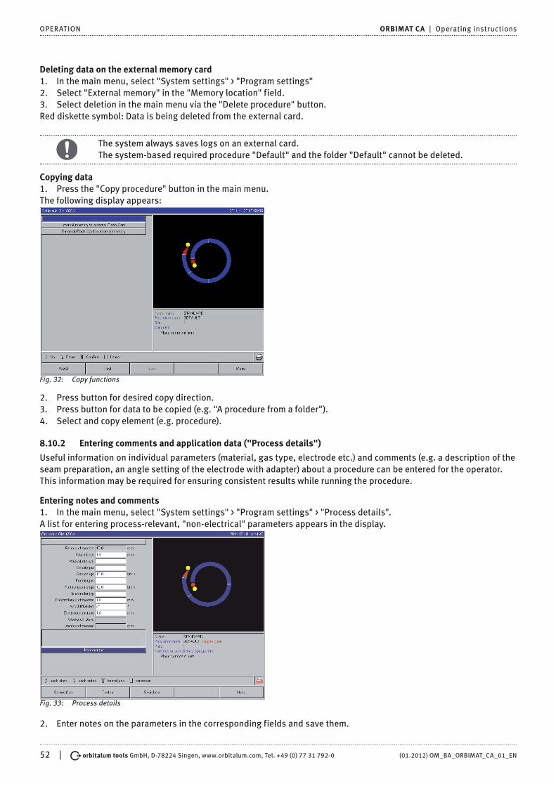
52 | orbitalum tools GmbH, D-78224 Singen, www.orbitalum.com, Tel. +49 (0) 77 31 792-0 (01.2012) OM_BA_ORBIMAT_CA_01_EN
OPERATION ORBIMAT CA | Operating instructions
Deleting data on the external memory card1. In the main menu, select "System settings" > "Program settings"2. Select "External memory" in the "Memory location" field.3. Select deletion in the main menu via the "Delete procedure" button.Red diskette symbol: Data is being deleted from the external card.
The system always saves logs on an external card.The system-based required procedure "Default" and the folder "Default" cannot be deleted.
Copying data1. Press the "Copy procedure" button in the main menu.The following display appears:
Fig. 32: Copy functions
2. Press button for desired copy direction.3. Press button for data to be copied (e.g. "A procedure from a folder").4. Select and copy element (e.g. procedure).
8.10.2 Entering comments and application data ("Process details")
Useful information on individual parameters (material, gas type, electrode etc.) and comments (e.g. a description of the seam preparation, an angle setting of the electrode with adapter) about a procedure can be entered for the operator. This information may be required for ensuring consistent results while running the procedure.
Entering notes and comments1. In the main menu, select "System settings" > "Program settings" > "Process details".A list for entering process-relevant, "non-electrical" parameters appears in the display.
Fig. 33: Process details
2. Enter notes on the parameters in the corresponding fields and save them.

(01.2012) OM_BA_ORBIMAT_CA_01_EN orbitalum tools GmbH, D-78224 Singen, www.orbitalum.com, Tel. +49 (0) 77 31 792-0 | 53
ORBIMAT CA | Operating instructions OPERATION
To enter other information: 3. Press "Comment" button.The comment field appears in the display.
Fig. 34: Comments
4. Highlight input field, enter text and save.
8.10.3 Working with external memory cards
Supported storage media:• CF cards• SD cards• MMC cards• Smart Media cards• Sony Memory Sticks
X Ensure that the memory card has "FAT formatting".
Available functions:• Saving and reading procedures• Saving of logs and procedures for further processing externally with special external software (OrbiProg CA)• Backing up, restoring and updating system data. This system data is essentially the operating software itself, the
library of the available weld heads, the auto programming database and the various operating languages of the software
Inserting external memory card X Push card into the appropriate slot of the card reader.
A diskette symbol appears in the bottom right-hand corner of the display.
Is there no diskette symbol?1. Remove memory card from the slot.2. Disengage card reader using the ejector, remove it from the housing and insert it again.3. Insert memory card into the slot again.
Using external memory cardUse depends on the software version.
Machines supplied before May 2008 (software version lower than 0.2.00):The external memory card must be "activated".1. In the main menu, select "System settings" > "Program settings".2. Select the "External card" option in the "Procedure space" field.The diskette symbol at the bottom right appears red. The memory card is activated as the storage medium.When writing and reading, the software no longer uses the internal memory, but will use the external memory card instead.

54 | orbitalum tools GmbH, D-78224 Singen, www.orbitalum.com, Tel. +49 (0) 77 31 792-0 (01.2012) OM_BA_ORBIMAT_CA_01_EN
OPERATION ORBIMAT CA | Operating instructions
Machines supplied after May 2008 (software version from 0.2.00 onwards):An external memory card is detected automatically (diskette symbol visible in the display).The selection between internal and external memory is offered for all functions.
Write/read logs to/from memory cards:Logs are always saved on the external memory card, as they are generally only used externally, e.g. on a PC with the "OrbiProgCA" program.
Activating log for a weld process
D External memory card inserted1. In the main menu, press softkey 1 "Weld" or softkey 2 "Test".2. Select the "Yes" option in the "Save log files" field.During the welding process, the logs are saved on the external memory card.If an external memory card is not inserted, an error message appears at the end of the welding process.
To always activate saving of the logs for a procedure:: X Save procedure with activated option.
Reading and evaluating a log
D External software "OrbiProgCA" installed on a PC. X Push external memory card into a reading device on the PC.
– or – X Connect card reader to the PC with USB extension cable.
– or – X Eject card reader and connect to PC with USB plug on back.
The logs can also be brought up in the display of the machine. X Display data of the logs (actual current values, weld speed and arc voltage) as a table in the display.
8.10.4 Viewing and printing data
Configuring printer
D External printer connected, if applicable X Select the desired printer in the main menu "System settings" > "Printer selection".
Select "internal" for internal printer. In addition, select the "Yes" option for "Small font for internal printer". – or – Select "LPT" for external printer. In addition, select the "No" option for "Small font for internal printer".
A symbol for the printer appears in the bottom right of the display.
When selecting the option "Small font for internal printer"/"Yes", the system can only print characters in the Latin character set.The "Small font for internal printer"/"No" option is absolutely necessary for all other character sets (Japanese, Russian, Chinese etc.), as the HPGL printer driver is activated for displaying these characters.
Viewing and printing saved procedures and logs1. In the main menu, select "Print procedure".2. Press one of the following buttons.
Folder tree: This function prints the available structure of the folders created in the system just like on a PCProcedure overview: Here, you are provided with a tabular overview of all procedures available on the machine, but without the procedure parameters.One procedure: Here you must select an individual procedure via the folder structure which is then printed.Log overview: Prints the tabular overview of all available procedures.All logs for a procedure: You proceed to a procedure using the folder structure here as well. Now, all logs which were generated when welding with this procedure are printed.

(01.2012) OM_BA_ORBIMAT_CA_01_EN orbitalum tools GmbH, D-78224 Singen, www.orbitalum.com, Tel. +49 (0) 77 31 792-0 | 55
ORBIMAT CA | Operating instructions OPERATION
One log: You go to a procedure using the folder structure here as well. You are now presented with the overview of all created logs with this procedure displayed as follows:
Fig. 35: Overview of the logs of a procedure
Each protocol has a unique number generated when the data record is saved (at the end of the current welding process), which is comprised of the current date and time.Example (see Fig.): Log file with the number 20080306 165852 (3/6/08 at 4:58:52 p.m.).
The logs are identified by color:Green with check:All measured actual values lie within the monitoring limits for alarm and abort.Yellow with exclamation mark:An alarm message is output while welding. The alarm limit values specified in the monitoring limits were undershot or overshot. The process was not aborted.Red with X:Welding was aborted. The monitoring limits were overshot/undershot or the operator initiated a "Stop".
If you now want to print an individual log after viewing it, select it. The machine will print a corresponding log with the respective active printer (internal or external).
Printing a log directly after welding
If the "direct printing" function is used, the data is not saved. The data is deleted after printing.The function for saving can also be activated.
To print a log without using a memory card or saving the data, proceed as follows: X Select the "Yes" option for "Print log files" in the "Welding" status.
Once the process is complete, the log is automatically printed by the active printer.
8.10.5 Editing data on a PC with the "OrbiProgCA" supplemental software
Using the external software, the procedure and log files generated by ORBIMATIC welding units of the entire C series (OM160/250C, OM165/300CB, OM165/300CA) can be saved and printed on an external PC.For data from the CA units, procedures can also be edited and the adjusted procedures transferred back to the machine.All procedures and logs can be printed with freeware in the PDF format.
8.11 Updating and backup functions for the softwareUpdating and backup functions for the following software components:• Machine operating software (system)• Auto programming files• Data of the individual weld heads (weld head list)• Files of the different operating languages (language files)

56 | orbitalum tools GmbH, D-78224 Singen, www.orbitalum.com, Tel. +49 (0) 77 31 792-0 (01.2012) OM_BA_ORBIMAT_CA_01_EN
OPERATION ORBIMAT CA | Operating instructions
The software components can be updated, saved and restored individually and independently of one another. To edit several software components, the steps must be carried out individually for each software component.
When executing the described functions for updating and saving the software, write, read and copy processes are carried out between the internal memory and an external card.
X Ensure that the machine is not switched off by the main switch or by the EMERGENCY-STOP function. – The operating software can be damaged due to incomplete transfer of the data, and it might
not be possible to start the machine again in this case.
8.12 Updating software components
Update with a new version of ORBIMATIC (can be obtained via Internet)1. Insert the memory card obtained from ORBIMATIC into the card reader.2. In the main menu, select "System files" > "Update".3. Select software component.4. Follow the instructions on the display.The update lasts a few minutes, and it may be necessary to restart the machine.
8.13 Saving software componentsSave existing version on a memory card.After backing up, the card can be read using the "Update" function if necessary.
Recommendation: X Save all software components (system, auto programming, header list and language files).
1. Insert memory card into the card reader.2. In the main menu, select "System files" > "Save".3. Select software component.4. Follow the instructions on the display.
8.14 Restoring software componentsIn case of problems with new program versions or a faulty update, the software can be reset to the version previously used.1. In the main menu, select "System files" > "Restore".2. Select software component.3. Follow the instructions on the display.
8.15 Working in other languagesCurrently, the following languages are available in the standard scope of delivery of each CA power source:German, English, Spanish, French, Italian, Polish, Hungarian, Danish, Turkish, Russian, Chinese, Japanese and Korean.
8.15.1 Changing the language
In the main menu, select "System settings" > "Language".Select desired language and confirm.The display changes to the main menu with the selected language.
Did you select the wrong language?If the wrong language was selected and you can no longer understand the text in the display, proceed as follows:1. Press softkey 5.The system switches to the main menu.2. In the main menu, select the last entry.The "System settings" menu appears in the display.3. In the sub-menu, select the last entry.The "Language" menu appears in the display.4. The list of available languages appears.5. Select correct language and confirm.

(01.2012) OM_BA_ORBIMAT_CA_01_EN orbitalum tools GmbH, D-78224 Singen, www.orbitalum.com, Tel. +49 (0) 77 31 792-0 | 57
ORBIMAT CA | Operating instructions OPERATION
8.15.2 Printing data in another language
When the language is changed, all output messages, parameter names etc. are translated to the selected language.Comments on the procedures or logs which were entered by the operator are not translated.
The procedures and logs are printed in the respective selected language of the operating software.
Printing a procedure on the machine1. Change language of the software to the desired language.2. Print procedure.
Printing procedure on a PC1. Save procedure to memory card.2. Open program on PC with the "OrbiProgCA" software and set language.3. Print procedure.
Printing a log1. Change language of the software to the desired language.2. Save log to memory card.3. Print log.
8.15.3 Creating a new operating language
A language file can be created with the collaboration of ORBIMATIC.
8.16 Importing programs from other ORBIMATIC power sourcesThis function is implemented starting with software version 0.1.05 (2/28/07). Thus procedures can be imported from ORBIMATIC devices which are either no longer being produced or which work with a different operating system.A procedure import to any CA machine is possible from the following units:• ORBIMAT 160 C, 250 C, 300 C• ORBIMAT 165 CB, 300 CBWhen importing, the procedures are transferred in the format OM 165/300CA and can then be used in the machine. Conversion in the other direction (procedure from the CA for use in the machines mentioned above) is not possible.
Importing procedures1. Save the procedures to be transferred to the initial machine on a memory card.2. For OM 160 C, OM 250 C or OM 300 C: An adapter from PCMCIA to a medium which is readable by the card reader of
the CA machine (CF, SD, SM, MMC, Sony Memory Stick) is required.If the procedures are saved on an external PC:
Z Transfer procedures to a memory card. Create a "Programs" folder here.This structure is required for identifying the procedures on the CA.
Z Copy procedures to this folder. Z Copy folder to the top level of the memory card.
3. Push memory card into the card reader of the machine.The diskette symbol appears in the display.4. In the main menu, select "System settings" > "Service" > "Import procedures".The folder structure of the machine appears in the display.
Z To create a new folder, select "New folder", enter a name and confirm.5. Select folder.The data is transferred and converted in the internal memory of the machine. The original procedure names, comments etc. remain in tact on the memory card.
8.17 Special keyboard commandsThe following commands can be entered using the external keyboard.
• VER Display software version
• SER Display service screen

58 | orbitalum tools GmbH, D-78224 Singen, www.orbitalum.com, Tel. +49 (0) 77 31 792-0 (01.2012) OM_BA_ORBIMAT_CA_01_EN
OPERATION ORBIMAT CA | Operating instructions
• RES Brings you back to the main menu and executes a "software reset" if software-related problems are occurring (also possible via simultaneous pressing of softkeys 1 + 5).
• ERR Printing/deletion of system error messages
• SLO Switches the slope representation from % (standard) to seconds
8.18 Operation of the system with other mains voltages (OM 165 CA only)The OM 165 CA machine features a "wide range" input for the mains voltage (input voltage).The machine can be set in the voltage range from 90–260 V at a frequency of 50–60 Hz.For operation on e.g. 115 V (or any other voltage in the range stated above), the operator does not need to switch anything or make any settings or adjustments.In 115 V operation, higher input currents arise with otherwise even loading of the machine. The weld current is automatically limited to 100 A if a mains voltage of less than 200 V is active.
The machine detects the mains voltage automatically and does not permit currents over 110 A to be entered when programming the system.Procedures containing current values over 110 A cannot be started.
X Ensure that an appropriate power plug is used for the power connection. X Have the power plug changed if necessary.

(01.2012) OM_BA_ORBIMAT_CA_01_EN orbitalum tools GmbH, D-78224 Singen, www.orbitalum.com, Tel. +49 (0) 77 31 792-0 | 59
ORBIMAT CA | Operating instructions SERVICE AND TROUBLESHOOTING
9. SERVICE AND TROUBLESHOOTING
9.1 Performing service work X In the main menu, select "System settings" > "Service".
The following display appears:
Fig. 36: Service menu
9.1.1 Pumping out water
Use when changing the cooling water and emptying the tank in case of longer machine standstill1. Connect drain hose on the flow connection (blue).2. Lead drain hose into a suitable container to catch the water (approx. 2.5 liters).3. Press "Pump out water" button.A message appears. The water is pumped out of the flow connection of the machine (blue) without the water sensor in the return being able to interrupt the process. To protect the pump against dry running, this process is limited in time to approx. 30 seconds.4. Select "Abort" when the water is fully pumped out to avoid unnecessary dry running of the pump.If the tank is not pumped empty:
X Start process again.
Additional information can be found in "Commissioning water pump" see Sec. 7.3.2, Page 25.
9.1.2 Performing motor calibration
Use in checking and correcting the motor speed.If several weld heads of the same type are used, a motor calibration should always be carried out before use.If using different weld head models, this is not required, as the machine saves a separate deviation for each head model.Continuously large and constantly different speed deviations are an indicator of a defect in the power source or weld head if this cannot be compensator for via motor calibration.1. Press "Calibrate motor" button.The rotor moves to the home position and then carries out one complete revolution at a speed which is realistic for the welding process. The time is measured during the revolution. The (actual) speed which can be calculated is compared to the default value. The deviation is displayed in the speed in percent.Properly calibrated heads generally mean deviations under 1%.A message appears: "Do you want to save the new calibration data?"2. If the deviation is less than 1%: Confirm message with "No".3. If the deviation is greater: Confirm message with "Yes" and save value.The machine is aware of the fault of the current connected weld head and compensates for it in the process.

60 | orbitalum tools GmbH, D-78224 Singen, www.orbitalum.com, Tel. +49 (0) 77 31 792-0 (01.2012) OM_BA_ORBIMAT_CA_01_EN
SERVICE AND TROUBLESHOOTING ORBIMAT CA | Operating instructions
Fig. 37: Motor calibration
WARNING
If a display appears (see Fig. 37), the weld head can be calibrated.1. Ensure that the head can rotate freely (electrode?) and that there is no danger of injury.2. Message: Confirm "Weld head ready for calibration?" with "Yes".The weld head starts running.The calibration can be aborted at any time by pressing the rotary knob.
Motor calibration is only possible with heads which have a limit switch.
9.1.3 Adjusting an external printer
Adjust printing of data when using an external (A4) printer.Example: Printing data on letter paper1. Press "External printer setup" button.The following display appears:
Fig. 38: Printer - Settings (external)
2. Select and highlight fields and enter desired values.
9.1.4 Switching on an internal printer
Inserting a new paper rollThis function is used exclusively for insertion of a new paper roll into the internal printer.

(01.2012) OM_BA_ORBIMAT_CA_01_EN orbitalum tools GmbH, D-78224 Singen, www.orbitalum.com, Tel. +49 (0) 77 31 792-0 | 61
ORBIMAT CA | Operating instructions SERVICE AND TROUBLESHOOTING
1. Switch on the "Internal printer" button.The button for paper feed is activated.2. Open printer hood and cover of the printer.3. Remove empty paper sleeve with the axis. Remove any paper present in the printer by
pressing the button on the printer (line advance). Do not pull on the paper here!4. Slide a new paper roll onto the axis and insert it into the cut-out of the housing
provided for mounting the axis so that the axis audibly engages. Attach paper roll in such a way that the paper rolls off toward the back. Attach axis as shown on the sticker in the paper compartment.
5. Cut off paper start straight and insert it into the printer.6. Move paper forward by pressing the line advance button. Paper is not to be pulled through by hand!7. Guide paper through the slot in the cover and close cover again.
Changing an ink ribbon1. After changing the cover, push the part of the ink ribbon cassette marked "PUSH"The ink ribbon comes out of the drive shaft on the opposite side.2. Remove ink ribbon from above.3. Using the rotary knob (see arrow for rotation direction) which protrudes on one side,
tighten the external part of the new ink ribbon and insert cartridge into the printer. 4. Insert free end of the ink ribbon into the slot through which the paper is also led out.The paper is guided between the ink ribbon cartridge and the free end of the ink ribbon.5. Tighten ink ribbon again if necessary and close printer hood.
9.1.5 Printing a test page
X Press "Print test page" button.A test page with a mixed character set is output on the printer which has been activated (internal or external).
9.1.6 Service screen
View current status of all digital or analog input and output signals of the control computer.• Digital In: Current values of the digital inputs of the computer• Digital Out: Current values of the digital outputs of the computer• Analog In: Current values of the analog inputs of the computer• Analog Out: Current values of the analog outputs of the computer• Inverter: Status of the serial interface used for communication between computer and power source (RS232)• Actual Val: Display of the current actual value of the running process calculated from the information of the analog
inputs or serial inverter interface
1. Press "Service Screen" button.The following display appears:
Fig. 39: Service Screen

62 | orbitalum tools GmbH, D-78224 Singen, www.orbitalum.com, Tel. +49 (0) 77 31 792-0 (01.2012) OM_BA_ORBIMAT_CA_01_EN
SERVICE AND TROUBLESHOOTING ORBIMAT CA | Operating instructions
2. Press "Service Screen" button again.The graphical view of the current weld procedure appears in the display.
Displaying Service screen during a running welding process X Enter letter sequence SER (for SERVICE) on the external keyboard.
The Service screen on the running welding process appears in the display.
9.1.7 Info
Information on the currently used software version and Serial No. of the machine.
Info ansehen X Enter letter sequence VER (for VERSION) on the keyboard.
9.2 Possible application/operating errors
9.2.1 Uneven weld seam ("current fluctuations")
ObservationIs the weld seam uneven?
Possible causes• Are current fluctuations the cause?The OM 165 CA unit, for example, compensates possible current fluctuations in the mains in the range from 85–260 V.If you do not receive an error message from the system during welding, the weld current is, with 99% certainty, within the limit values set for the respective procedure.• Pipe tolerances• Uneven weld seams can occur if classic forming gases (which contain up to 30% hydrogen in addition to the
nitrogen) are used with cassette heads inside the pipe. The hydrogen ends up in the welding pocket in an undefined quantity and affects the welding result "randomly" as an energy carrier.
Remedy X Always use the same gas inside the pipe as in the weld head.
9.2.2 Annealing colors inside/outside
Possible causes• Annealing colors arise only as a result of a reaction between the base material and another substance under the
effect of a high temperature introduced into the material by the arc. This other substances can come in the form of oxygen, humidity or other impurities..
• Parts of grinding disks which remain on the workpiece as residue.• Annealing colors at the start of the seam: Gas pre purge time may be too short. Annealing colors gradually fade as
welding progresses.• Annealing colors at the end of welding: Gas post purge too short or (closed) weld head possibly opened too early.• Depending on the design, more annealing colors occur on the outside of the pipes with open weld heads
(TP series) than with cassette heads.• TP weld heads invariably react with more sensitivity to any drafts present. A draft can "blow away" the gas cover,
thereby causing extreme annealing colors.
Remedy X Clean pipe ends with a suitable solvent which evaporates without leaving residue (e.g. acetone). X Ensure that the pipe ends are bare metal. X Remove any and all oils and greases (from sawing or bending). X Ensure that the following parameters are set:
• Gas quantity set sufficiently long, sufficient volume• Recommendation: Approx. 7 L/min for the weld gas and approx. 2–3 L/min for the forming gas• Gas pre purge time/gas post purge time set optimally

(01.2012) OM_BA_ORBIMAT_CA_01_EN orbitalum tools GmbH, D-78224 Singen, www.orbitalum.com, Tel. +49 (0) 77 31 792-0 | 63
ORBIMAT CA | Operating instructions SERVICE AND TROUBLESHOOTING
9.2.3 Wide seam and no weld penetration
When welding without a filler wire, is the seam unusually "wide" without going "deep"?Does increasing the current amplify the effect?Is proper weld penetration (even on comparatively thinner walls) not possible?
Possible causesThe so-called "Marangoni effect".In stainless steel, the percental component of sulfur is always limited upward, as sulfur forms inclusions (manganese sulfide) which lead to small craters and other defects and which ultimately reduce the corrosion resistance of the material. For this reason, the sulfur content is limited, e.g. to max. 0.030%. With this level of sulfur, welding is no problem.If the sulfur content is reduced further (approx. 0.005% or lower), the so-called "convection streams" in the melt pool (in simplified terms) tend to flow more horizontally and on the surface. This leads to widening of the seam without penetration.
Remedy X Carry out a material analysis for confirmation. X Change material if appropriate (it may be sufficient to just change the batch). X Weld with filler wire so that a correspondingly higher sulfur content arises in the melting pool thanks to the wire.
9.2.4 Uneven seam/hole formation at the end of welding
Do the weld seams look as if the torch "moved sideways" in an uncontrolled fashion?Does the seam not remain centered over the joint, instead pulling to one side or moving "back and forth"?
Possible causes and remedies• When welding pipe and molded part: "Marangoni effect".
The sulphur content tends to be high with materials for machining. The effect is seen on one side of the pipe joint with the result of a seam which is heavily asymmetrical to the joint. The root inside the pipe is then often formed fully outside and next to the pipe joint.
• If the seam regularly wanders off to the side only in one or two places when welding, the corresponding different material composition in the base material and in the seam is responsible for the effect with a longitudinal pipe seam.
X Shorten arc gap somewhat.• Gas quantity set too high (weld gas or forming gas):
If an excessive gas quantity is set for small cassette heads (especially OW12), turbulence occurs in the pocket, which can lead to an extremely irregular arc. The same applies if too much forming gas is used and it comes out at the weld joint at relatively high pressure.
X Regulate gas quantity.• Excessively high forming gas pressure:
Heavy outward swelling of the seam with a type of "hollow groove" inside the pipe. Hole formation also often occurs at the end of welding if the excessive pressure of the gas can only be "relieved" over the liquid melt pool. With cassette weld heads in particular, liquid metal dripping in the head can cause considerable consequential damage.
X Regulate forming gas pressure.• Worn electrode without proper grinding:
The "attachment" point of the arc often "dances" back and forth on the electrode. With a poor-quality electrode, lateral migration of the arc from the electrode can be observed now and then. The reason for this can be that the alloy components in the base material are not evenly distributed.
X Grind electrode properly.
9.2.5 Ignition problems
The ignition generator generates ignition pulses with a voltage of up to 8,000 V. These ignition pulses can be a considerable source of disruption (especially for computer-based control). The ignition pulses are introduced to the electrode with high-voltage insulation via the hose assembly. Upon ignition, a current flow of potentially several hundred amperes can arise in the weld circuit and be correspondingly disruptive (magnetic fields around the conductor and other high-frequency fields). The machine controller is shielded from these disruptive fields. If problems are occurring with the arc ignition, malfunctioning of the computer or a corresponding defect in the system cannot be ruled out.

64 | orbitalum tools GmbH, D-78224 Singen, www.orbitalum.com, Tel. +49 (0) 77 31 792-0 (01.2012) OM_BA_ORBIMAT_CA_01_EN
SERVICE AND TROUBLESHOOTING ORBIMAT CA | Operating instructions
Information on possible electrical fault sources: see Sec. 9.3, Page 64: "List of error messages"
Possible causes• Poor electrode quality, worn or scaled electrode.• Poor ground contact (open head to ground terminal).• Worn weld current plug, poor contact.• Rusty or soiled pipe surface.• No gas, wrong gas (never use carbon dioxide, even if it is mixed with argon!) or excessively short gas pre purge time.• Excessively large arc gap.• Humidity in weld head.• Excessively long hose assemblies (extensions).
Remedy X Eliminate possible causes. X Recommendation: Do not exceed a total hose assembly length of 15 m.
9.2.6 Machine does not start
If the operating voltage is active when the machine is started, the control computer starts the software.Does nothing appear in the display after the machine is started?Is the red "Stop" LED on the front of the machine lit up?
Possible causes and remedies X Check mains connection. X Ensure that main switch is lit up.
• Dummy plug is missing from remote control connection.• EMERGENCY-STOP function of a (possibly) connected remote control is activated.
X Insert dummy plug. X Unlock EMERGENCY-STOP button of the remote control.
9.3 List of error messagesNo. Error message Explanation/Elimination
01 Warning A "warning" appears in the "info area" of the display (directly below the mains voltage information during the process). The message can be combined with the parameters of voltage, current or speed and the "high" or "low" specification. The message shows that the limit value specified in the monitoring limits for the alarm were overshot or undershot for the corresponding parameter.
Example:"Warning: Low speed": The limit value of the weld speed specified for the alarm was reached during the "low-current time".This can be overshooting or undershooting. If one of the abort values is also reached, the process is aborted and another message is output.
02 Gas problem The process was aborted due to a problem with the gas. X Check hoses, bottle and pressure reducer. X Check sensor even if the gas is flowing in the sufficient quantity.
The message also appears outside the welding process if the gas was switched on using the gas/water button and no gas is flowing.
03 Cooling water problem The process was aborted due to a problem with the cooling water. X Check hoses, water level in tank and pump operation. X Check sensor even if the water is flowing in the sufficient quantity. X Check water flow: Disconnect water return from machine for testing).
This message also appears outside the welding process if the water was switched on using the gas/water button and no water is flowing.

(01.2012) OM_BA_ORBIMAT_CA_01_EN orbitalum tools GmbH, D-78224 Singen, www.orbitalum.com, Tel. +49 (0) 77 31 792-0 | 65
ORBIMAT CA | Operating instructions SERVICE AND TROUBLESHOOTING
04 Error in ext. input If device connected to external error input triggered the error.If a device is not connected to the external error input:
X Deactivate monitoring function in the system settings.
05 Current fault Used in connection with a deviation of the weld current.Example: "Warning: Low current fault", see message 01
06 Current abort The weld current has overshot or undershot the limits defined for aborting in the monitoring limits and the process was interrupted.
X Check limit values: Possibly set too close together.Excessive resistance in weld circuit (ground connection, rotor, current water cable): The machine can no longer keep the programmed weld current (setpoint value) stable within the specified limits.
07 Low The limit value set for the low pulse of the corresponding parameter was reached; see also message 01.
08 Voltage The message appears as "Warning: Voltage". The limit values specified in the monitoring limits for the alarm were overshot or undershot.
X Check limit values and heed information in "Monitoring functions" see Sec. 8.9, Page 50.
Cause for excessive arc voltage:• High transition resistances in weld circuit (plug, ground contact etc.)For cassette heads: Worn current water cable.
09 Voltage abort The limit values for aborting with regard to arc voltage specified in the monitoring limits are overshot or undershot.
X Check limit values and heed information in "Monitoring functions" see Sec. 8.9, Page 50.
Cause for excessive arc voltage:• High transition resistances in weld circuit (plug, ground contact etc.)For cassette heads: Worn current water cables.
10 Speed Supplement to "Warning". The limit values specified in the monitoring limits (warning) of the speed were overshot or undershot.
X Check limit values. X Check weld head speed. X Carry out motor calibration if necessary.
11 Speed abort The weld speed has overshot or undershot the limit values specified for abortion in the monitoring limits and the process was aborted.Check limit values; they may be too close together.Possible causes for speed aborting:Mechanically blocked, jamming or defective weld heads
X Check whether the weld head can be moved manually (or with the remote control). X Carry out motor calibration if necessary.
12 Time limit for high-voltage ignition exceeded
After the ignition device was switched on, an arc was not ignited within approx. 3 seconds. The process is interrupted.Causes for failed arc ignition:• Fault in marginal conditions of the process, e.g. forgotten ground connection
see Sec. 9.2.5, Page 63.
13 Inverter Fault in serial communication (RS232) between PC controller and inverter. X Switch machine off and then, after 30 seconds, switch it on again.
Is the fault still occurring? X Contact your specialist dealer or ORBIMATIC.
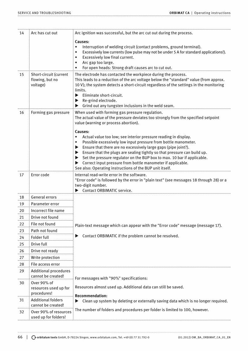
66 | orbitalum tools GmbH, D-78224 Singen, www.orbitalum.com, Tel. +49 (0) 77 31 792-0 (01.2012) OM_BA_ORBIMAT_CA_01_EN
SERVICE AND TROUBLESHOOTING ORBIMAT CA | Operating instructions
14 Arc has cut out Arc ignition was successful, but the arc cut out during the process.
Causes:• Interruption of welding circuit (contact problems, ground terminal).• Excessively low currents (low pulse may not be under 5 A for standard applications!).• Excessively low final current.• Arc gap too large.• For open heads: Strong draft causes arc to cut out.
15 Short-circuit (current flowing, but no voltage)
The electrode has contacted the workpiece during the process.This leads to a reduction of the arc voltage below the "standard" value (from approx. 10 V); the system detects a short-circuit regardless of the settings in the monitoring limits.
X Eliminate short-circuit. X Re-grind electrode. X Grind out any tungsten inclusions in the weld seam.
16 Forming gas pressure When used with forming gas pressure regulation.The actual value of the pressure deviates too strongly from the specified setpoint value (warning or process abortion).
Causes:• Actual value too low; see interior pressure reading in display.• Possible excessively low input pressure from bottle manometer.
X Ensure that there are no excessively large gaps (pipe joint?). X Ensure that the plugs are sealing tightly so that pressure can build up. X Set the pressure regulator on the BUP box to max. 10 bar if applicable. X Correct input pressure from bottle manometer if applicable.
See also: Operating instructions of the BUP unit itself.
17 Error code Internal read-write error in the software."Error code" is followed by the error in "plain text" (see messages 18 through 28) or a two-digit number.
X Contact ORBIMATIC service.
18 General errors
Plain-text message which can appear with the "Error code" message (message 17).
X Contact ORBIMATIC if the problem cannot be resolved.
19 Parameter error
20 Incorrect file name
21 Drive not found
22 File not found
23 Path not found
24 Folder full
25 Drive full
26 Drive not ready
27 Write protection
28 File access error
29 Additional procedures cannot be created! For messages with "90%" specifications:
Resources almost used up. Additional data can still be saved.
Recommendation: X Clean up system by deleting or externally saving data which is no longer required.
The number of folders and procedures per folder is limited to 100, however.
30 Over 90% of resources used up for procedures!
31 Additional folders cannot be created!
32 Over 90% of resources used up for folders!

(01.2012) OM_BA_ORBIMAT_CA_01_EN orbitalum tools GmbH, D-78224 Singen, www.orbitalum.com, Tel. +49 (0) 77 31 792-0 | 67
ORBIMAT CA | Operating instructions SERVICE AND TROUBLESHOOTING
33 The procedure cannot be loaded!
Procedure cannot be loaded after switch-on.
When the machine is switched on, the last used program is loaded. If this is not possible (e.g. memory card removed), the default program is loaded.
X Contact ORBIMATIC if the problem cannot be resolved.
34 A problem occurred when saving the procedure.The error appears in "plain text" (see messages 18 through 28) or as a two-digit number.
35 An error entry was created in the error log. The new error entry appears in the display in English. The error log can be read out for service purposes.
View error log: X Enter the letter sequence ERR on the external keyboard. [ Do not delete error log, as this information is required for service purposes.
36 File with inverter characteristic cannot be opened!Default values are used.
File with characteristics cannot be read. Current adjustment of the machine ineffective.
A file generated during current adjustment is stored on the CF card of the machine: During calibration, a digital adjustment is carried out, where the differences between the setpoint and actual values and the measured values of a calibrated measuring unit can be recorded point by point and saved in a file.
If the file is not readable, the error coefficients are given the default value (1). This makes the current adjustment carried out by ORBIMATIC ineffective.
X For applications which provide data monitoring and actual value recording, stop working with the machine.
X Contact ORBIMATIC to restore the calibration data.
37 Auto programming failed!The auto programming file may be missing or corrupt.
Auto programming error.
Causes:• The combination of pipe diameter and wall thickness lie outside the value range
of auto programming (e.g. wall thicknesses over 4 mm) X Use other parameters.
• Data of the database on the internal CF card not present or not readable X Contact ORBIMATIC to restore the data.
38 External storage medium not found!The card reader may not have a card inserted
Access to external memory card not possible. X Check whether the memory card is detected by the system
(diskette symbol in the display). X Reset the card reader: Disengage card reader, remove it from the slot and insert it again. X Check whether the memory card is defective or has an unreadable format. X Contact ORBIMATIC service if the problem cannot be resolved.
39 Error when saving log
Software conflicts due to damaged files or files with unreadable contents.The message is followed by the error in "plain text" (see messages 18 through 28) or as a two-digit number.
40 Procedure file cannotbe opened!
41 Log file cannotbe opened!
42 Some currents are set too high.They cannot be achieved with a 115 V mains voltage!(OM 165 CA only)
OM 165 CA only.
Machine connected to mains network of less than 200 V AC. The maximum weld current is limited to 100 A. Procedure with higher weld current has been started.
43 An error occurred while reading the fileFAILURES.TXT!
After entering ERR on the external keyboard: Internal error log ("Failures.txt" file) is not present or is damaged.

68 | orbitalum tools GmbH, D-78224 Singen, www.orbitalum.com, Tel. +49 (0) 77 31 792-0 (01.2012) OM_BA_ORBIMAT_CA_01_EN
SERVICE AND TROUBLESHOOTING ORBIMAT CA | Operating instructions
44 No weld head connected!
Procedure started, no weld head connected to the machine.
Weld head is connected?• Weld head not encoded• Voltage supply to weld head defective. The operating buttons in the weld head are
not working. X Contact ORBIMATIC service.
45 Incorrect weld head connected!
The currently connected weld head is not the same as the weld head in the started procedure.
X Select connected weld head in the procedure.– or –
X Connect the weld head selected in the procedure to the machine.
Are the weld head models identical, but the message appears anyway? X Contact ORBIMATIC service.
46 The procedure contains parameters which lie outside the limit values for the selected weld head!
Weld head changed in procedure. Weld head does not match the one in the parameters.
The weld head list of the machine contains the parameters of the weld heads which can be connected to the machine, e.g. the maximum rotation of the rotor, the maximum pipe diameter to be welded and the maximum permissible current.
X Adjust parameters of the program to the selected weld head.
9.4 Status LED indicatorsThe back of the machine is equipped with five LED rows (A through E) with eight LEDs each.The status of all important internal signals of the unit is signaled by the LEDs. The LED indicators work independently of the control computer of the machine.
Row A:Red LEDs (row A) are lit up: Internal control fuses defective.
Row B:Green LEDs (row B) are lit up: Internal control voltages for PC, motor, valves etc. are active.For OM 165 CA and OM 300 CA units: Indicator B2 – printer power supply unit. Indicator lights up if the internal printer was switched on (by a print command).
Yellow LEDs:Indicate various functions. Switched on or off depending on the operating condition of the system and the function.
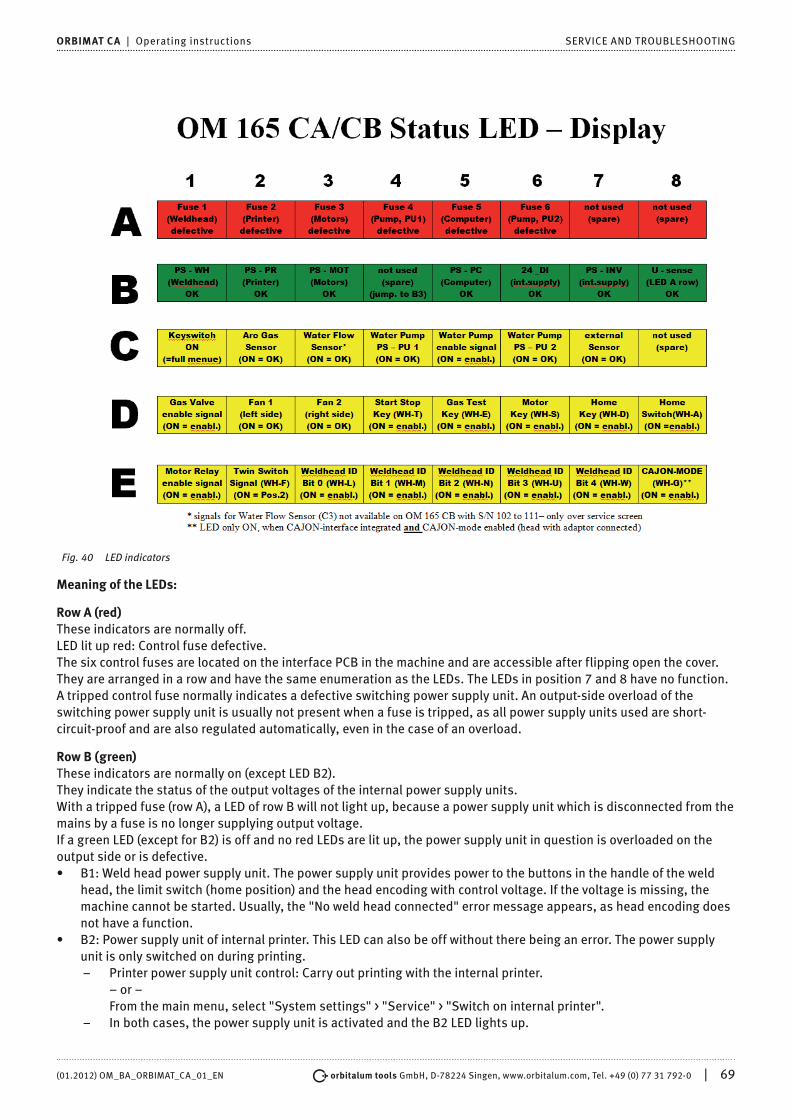
(01.2012) OM_BA_ORBIMAT_CA_01_EN orbitalum tools GmbH, D-78224 Singen, www.orbitalum.com, Tel. +49 (0) 77 31 792-0 | 69
ORBIMAT CA | Operating instructions SERVICE AND TROUBLESHOOTING
Fig. 40 LED indicators
Meaning of the LEDs:
Row A (red)These indicators are normally off.LED lit up red: Control fuse defective.The six control fuses are located on the interface PCB in the machine and are accessible after flipping open the cover. They are arranged in a row and have the same enumeration as the LEDs. The LEDs in position 7 and 8 have no function.A tripped control fuse normally indicates a defective switching power supply unit. An output-side overload of the switching power supply unit is usually not present when a fuse is tripped, as all power supply units used are short-circuit-proof and are also regulated automatically, even in the case of an overload.
Row B (green)These indicators are normally on (except LED B2).They indicate the status of the output voltages of the internal power supply units.With a tripped fuse (row A), a LED of row B will not light up, because a power supply unit which is disconnected from the mains by a fuse is no longer supplying output voltage.If a green LED (except for B2) is off and no red LEDs are lit up, the power supply unit in question is overloaded on the output side or is defective.• B1: Weld head power supply unit. The power supply unit provides power to the buttons in the handle of the weld
head, the limit switch (home position) and the head encoding with control voltage. If the voltage is missing, the machine cannot be started. Usually, the "No weld head connected" error message appears, as head encoding does not have a function.
• B2: Power supply unit of internal printer. This LED can also be off without there being an error. The power supply unit is only switched on during printing.
– Printer power supply unit control: Carry out printing with the internal printer. – or – From the main menu, select "System settings" > "Service" > "Switch on internal printer".
– In both cases, the power supply unit is activated and the B2 LED lights up.

70 | orbitalum tools GmbH, D-78224 Singen, www.orbitalum.com, Tel. +49 (0) 77 31 792-0 (01.2012) OM_BA_ORBIMAT_CA_01_EN
SERVICE AND TROUBLESHOOTING ORBIMAT CA | Operating instructions
• B3: Netzteil MOTOR power supply unit. The power supply unit provides operating voltage to the rotation motor and, if applicable, the motor of the cold wire supply unit.
• B4: No function, lights up (internally bridged to B3)• B5: PC controller power supply unit: The power supply provides voltage to the control computer. In case of a failure,
the system will not start, i.e. the display will remain dark.• B6: Internal voltage. Control voltage is provided by the control computer for supplying purely internal consumers:
Sensors for gas, water, temperature and the key switch. • B7: Internal control voltage of the inverter. No function; voltage is not used by the system at present.• B8: Internal control voltage for supplying the red LEDs. If this voltage fails (LED off), any defective fuses in the (red)
row A of the LED indicator can no longer be indicated. Failure is improbable, as it is formed from multiple power supply unit voltages.
Row C, D, E (yellow)• C1: Key switch. LED lights up if the key switch is in "programming mode" (i.e. "long menu"). If the LED is not lit up,
the power supply unit (see LED B6) has failed or the key switch is defective.• C2: Gas sensor. LED lights up if the gas sensor is reporting sufficient gas flow at the PC. Welding is not possible
without this signal. If the signal is not active shortly after the gas valve is opened, the gas quantity is still too low or the sensor is defective. A defective sensor can be deactivated temporarily via the menu item "System settings" > "System adjustments". Gas monitoring then no longer takes place. The switch-off is deactivated again the next time the entire system is restarted.
• C3: Water sensor. LED flashes when the water pump is switched on and cooling water is flowing. Fan wheel sensor which supplies one pulse per unit of water flow volume. The pulse frequency is therefore measured proportionally to the water quantity so that it can be recorded, calculated and ultimately displayed by the system. If the LED does not flash, the "Cooling water problem" message appears. The cause could be a defective pump, a "clogged" water circuit, a defective pump power supply unit or a defective sensor. A defective sensor can be deactivated temporarily via the menu item "System settings" > "System adjustments". Water monitoring then no longer takes place. The switch-off is deactivated again the next time the entire system is restarted.
• C4C6: Water pump power supply unit. Two 12 V power supplies (60 W each) are operated in series for the power required by the water pump (80 W at 24 V DC). These power supply units are only connected if needed (on primary side). Both LEDs light up when the water pump should be running. If only one LED lights up, a power supply unit is defective. The pump supplies water, but an error message appears due to the low current level.
• C5: Water pump ON. ON signal for the water pump from digital output of the control computer to the semi-conductor relay which switches on the power supply unit of the pump. The LED lights up if the water pump should be running.
• C7: Signal from external sensor. The LED indicates the status of an external device; it lights up if the status is "OK". The machine features a connection for an external sensor, e.g. for the connection of a residual oxygen meter (ORB 1001). Devices which are to be monitored for their status before welding begins can be connected here. The function must be activated via the menu item "System settings" > "System adjustments".
• C8: Not used (reserved)• D1: Gas valve ON. This signal (PC digital output) switches the internal gas valve. If the LED does not light up, there
is probably an error in the control computer.• D2/D3: Fan operation – OM 165 CA or OM 300 CA with ORBICOOL 3004: Two fans featuring speed feedback are
installed on the heat exchangers in these units. The LED indicates whether the fans are running. When using external water cooling (e.g. compressor cooling or from other manufacturer), these indicators do not have a function and are always off.
• D4: Start/Stop button. LED lights up when the button on the weld head is pressed. If the machine does not respond to this command, you can check whether the signal is arriving or the button on the weld head is defective. The check only makes sense if the voltage supply for the weld head is functioning (see LED B1).
• D5: Gas-test button. LED lights up when the button on the weld head is pressed. If the machine does not respond to this command, you can check whether the signal is arriving or the button on the weld head is defective. The check only makes sense if the voltage supply for the weld head is functioning (see LED B1).
• D6: Motor button. LED lights up when the button on the weld head is pressed. If the machine does not respond to this command, you can check whether the signal is arriving or the button on the weld head is defective. The check only makes sense if the voltage supply for the weld head is functioning (see LED B1).
• D7: 0-position (home) button. LED lights up when the button on the weld head is pressed. If the machine does not respond to this command, you can check whether the signal is arriving or the button on the weld head is defective. The check only makes sense if the voltage supply for the weld head is functioning (see LED B1).

(01.2012) OM_BA_ORBIMAT_CA_01_EN orbitalum tools GmbH, D-78224 Singen, www.orbitalum.com, Tel. +49 (0) 77 31 792-0 | 71
ORBIMAT CA | Operating instructions SERVICE AND TROUBLESHOOTING
• DD8: 0-position (home) switch. LED lights up when the home position is reached (for weld heads with limit switch). In case of problems with the return or during a motor calibration, you can determine whether the limit switch in the weld head is working.
• E1: Motor relay ON. LED lights up if one of the two motors should be running. This function is used to switch off all motor lines (rotation, tacho and wire) running to the weld head during ignition for reasons of interference resistance. The signal is a direct digital output of the control computer. If the LED is not lit up, the motors cannot run. There is probably a defect in the control computer.
• E2: Orbitwin switching. This signal is only relevant for a connected ORBITWIN and indicates switching between the two weld locations. The LED lights up if weld location 2 is selected. In the power source, this signal is used to switch between the two procedures.
• E3–E7: Head code, bit 0–4. The LEDs indicate the current present head code of the connected weld head (these are the bridges presented in the control plug or weld head). The indicator only works if the voltage supply for the weld head (B2) is active. The LEDs can be referred to for error analysis if the system detects a connected weld head incorrectly or not at all.
• E8: Encoder interface. LED signals the presence of a supplementary PCB which permits the operation of weld heads with digital encoder feedback. The LED only lights up if a corresponding weld head is connected. On standard machines, the LED is off.
9.5 Temporarily deactivating sensors and monitoring functions
SensorsCertain sensors can be deactivated temporarily. This can make sense, for example, when a defective gas sensor is present and work is to continue. Greater attention is required when working with the machine.The sensors cannot be deactivated permanently: Deactivation of the sensors for gas and water monitoring is reset each time the machine is switched off. The sensor is active again after the machine is restarted.
Monitoring limitsThe use of monitoring limits can also be deactivated.
External input for abortingIf an external device with the abort function is connected (e.g. residual oxygen meter), the function must be activated so that the abort signal is processed by the unit in the machine.If an external device is not connected, the function must be deactivated.
X When deactivating sensors and monitoring limits, be aware that the corresponding monitoring function is no longer active.
Example: With the gas sensor deactivated, the welding process is no longer interrupted if the gas bottle is empty. X Deactivate sensors only in cases where this is absolutely necessary.
1. In the main menu, select "System settings" > "System adjustments".The following display appears:
Fig. 41: System adjustments
2. Select the "No" option for "Gas flow sensor"/"Water flow sensor" for deactivation.

72 | orbitalum tools GmbH, D-78224 Singen, www.orbitalum.com, Tel. +49 (0) 77 31 792-0 (01.2012) OM_BA_ORBIMAT_CA_01_EN
SERVICE AND TROUBLESHOOTING ORBIMAT CA | Operating instructions
3. Select the "No" option for "Use of parameter limits" for deactivation of the warning messages and process aborting.
4. Select the "Yes" option for "External input for abort" and connected external unit.5. Press softkey 3 ("Save").
9.6 Setting date and time1. In the main menu, select "System settings" > "System adjustments".The following display appears:
Fig. 42: System adjustments
2. Highlight, activate and enter values for the "Year", "Month", "Day", "Hour", "Minute" and "Second" fields one after another.
3. Press softkey 3 ("Save").

(01.2012) OM_BA_ORBIMAT_CA_01_EN orbitalum tools GmbH, D-78224 Singen, www.orbitalum.com, Tel. +49 (0) 77 31 792-0 | 73
ORBIMAT CA | Operating instructions MAINTENANCE, SERVICE AND REMEDYING ERRORS
10. MAINTENANCE, SERVICE AND REMEDYING ERRORS
10.1 Maintenance
DANGER
Dangers of improper maintenance of the system.Various injuries and damage to property!
X Carry out maintenance as described in the "Maintenance" chapter.
DANGER
Improper access to and opening of the ORBIMAT machine.Electric shock!
X Disconnect machine from mains. X Disconnect all external devices connected to the machine (weld heads etc.). X Allow machine to cool down sufficiently before opening. X Allow only a professional electrician to access the electrical system. [ Never connect an opened system to the mains network.
10.1.1 Maintenance intervals
Time frame Activity
Daily X Check water level in tank (OM 165 CA) or in external cooling unit (OM 300 CA) and fill if necessary.
Frequent refilling of the cooling water may be necessary if the weld heads are changed frequently. 1. Nach einem Schweißkopfwechsel sicherstellen, dass dieser vollständig mit Wasser gefüllt ist (ca.
3 min laufen lassen – Taste: GAS/Wasser).2. Check cooling water level and refill if necessary.
The use of distilled water is not absolutely necessary. X If anti-freeze is used: Supplement with water appropriately. X Wipe off display with a slightly damp cloth. Do not use cleaning agents.
Monthly X Clean machine fully from the outside. X Check power cable, power plug and machine for mechanical damage. X Clean weld heads and check mains cable.
Recommendation: X Carry out motor calibration (even if the weld heads are suspected to be running properly).
Semi-annually
1. Pump out all cooling water.2. Add fresh cooling water and pump out all of this filling as well.3. Add anti-freeze (if necessary).4. Fill tank with clean tap water.5. Check frost-resistance of the mixture with a measuring device if necessary.
Annually Recommendation: X Have machine maintenance carried out once annually by ORBIMATIC or a service point authorized
by ORBIMATIC if it is in constant use.. X Carry out the following maintenance work:
1. Open unit and clean inside (compressed air).2. Carry out visual check (hoses, seals, loose parts etc.).3. Clean water filter (OM 300 CA only).4. Performance of the prescribed measurements for electrical safety of the machine (incl. log).5. Carry out current calibration incl. log.6. Carry out full machine test with all functions.
After 3 years X Replace buffer battery (PC).

74 | orbitalum tools GmbH, D-78224 Singen, www.orbitalum.com, Tel. +49 (0) 77 31 792-0 (01.2012) OM_BA_ORBIMAT_CA_01_EN
MAINTENANCE, SERVICE AND REMEDYING ERRORS ORBIMAT CA | Operating instructions
Regularly/As needed
Perform printer maintenance X Change paper and printer ink ribbon.
Blow out machineIn an extremely dusty environment, it may be necessary to blow out at shorter intervals.1. Disconnect machine from mains.2. Loosen the screws located in the hood.3. For OM 165CA: Also loosen the three screws at the water filling neck and the tank closure.4. Fold away display.5. Open hood upward carefully.6. Screw off the two side panels (incl. the handles) from the side frame if necessary.7. Blow out/clean machine.8. Screw side panels back on.9. Close hood again and screw it tight.
10.1.2 Storage
X If the machine will go unused for a longer period of time, dismantle the machine and store it in a suitable place. X Recommendation: Carry out the following activities before storage:
1. Clean machine.2. Remove cooling agent. For this purpose, loosen cooling water return of the weld head on the back of the unit and
pump out coolant supply into a container with the pump.
Storage conditions• Relative humidity <70 % • Temperature range –20 ... +40 °C, protected from dust
10.2 Service/Customer serviceOrdering spare parts: See separate spare part list.Eliminating errors:
X Please contact the responsible service department directly. X Please provide the following information:
– Machine model: (ORBIMAT 165 CA, ORBIMAT 300 CA, ORBIMAT 300 CA Compact, ORBIMAT 300 CA AC/DC, ORBIMAT 300 CA AC/DC Compact, ORBIMAT 300 CA AVC/OSC)
– Machine No.: (see rating plate)

(01.2012) OM_BA_ORBIMAT_CA_01_EN orbitalum tools GmbH, D-78224 Singen, www.orbitalum.com, Tel. +49 (0) 77 31 792-0 | 75
ORBIMAT CA | Operating instructions ENVIRONMENTAL PROTECTION AND DISPOSAL
11. ENVIRONMENTAL PROTECTION AND DISPOSAL
11.1 Electric tools and accessories
X Clean machine properly before disposal.
Used-up power tools and accessories contain a large amount of valuable raw materials and plastics which can be recycled.• Used electric and electronic devices contain parts which must be handled specially
as per EU guidelines.• We will properly dispose of devices and machines from orbitalum tools GmbH
purchased after August 13th, 2005 if they are sent to us postage-paid.• In the case of used devices which may represent a risk to human health or safety due
to contamination during use, we have the option of refusing return.• Devices and machines from orbitalum tools GmbH purchased before August 13th,
2005 are to be disposed of with a professional disposal company.• Important note for Germany: Do not dispose of machine at local dumps, as they only
operate in the commercial sector.
(nach RL 2002/96/EG)

76 | orbitalum tools GmbH, D-78224 Singen, www.orbitalum.com, Tel. +49 (0) 77 31 792-0 (01.2012) OM_BA_ORBIMAT_CA_01_EN
OVERVIEW WIRING DIAGRAM ORBIMAT CA | Operating instructions
12. OVERVIEW WIRING DIAGRAM
Abb. 1: Übersichtsplan

(01.2012) OM_BA_ORBIMAT_CA_01_EN orbitalum tools GmbH, D-78224 Singen, www.orbitalum.com, Tel. +49 (0) 77 31 792-0 | 77
ORBIMAT CA | Operating instructions EC DECLARATION OF CONFORMITY
13. EC DECLARATION OF CONFORMITY
13.1 ORBIMAT 165 CA | 300 CA
EG-KonformitätserklärungDeclaration of conformityDichiarazione di conformitàDéclaration de conformitéDeclaración de conformidad
Orbitalum Tools GmbHJosef-Schüttler-Straße 1778224 Singen, GermanyTel.: +49 (0) 77 31 792-0Fax: +49 (0) 77 31 792-524
as per Appendix II A of the EC Machinery Directive 2006/42/EC (MaschR) and EMC Directive 2004/108/EG.
Die Bauart der Maschine:The following product:Il seguente prodotto:Le produit suivant:El producto siguiente:
OM 165 CA Orbital Welding Power Source* incl. weld head OM 165 CB Orbital Welding Power Source* incl. weld head
OM 300 CA Orbital Welding Power Source* incl. weld head
OM 300 CB Orbital Welding Power Source* incl. weld head
* Incl. all accessory items optionally available from Orbitalum Tools, e.g. ORBITWIN, BUP Control, ORB 1001, ORBICOOL etc.
Seriennummer:Series number:Numero di serie:Nombre de série:Número de serie:
Baujahr / Year / Anno / Année / Año:
ist entwickelt, konstruiert und gefertigt in Übereinstimmung mit folgenden EG-Richtlinien:was designed, constructed and manufactured in accordance with the following EC guidelines:è stata progettato costruito e commercializzato in osservanza delle seguenti Direttive:a été dessiné, produit et commercialisé selon les Directives suivantes:ha sido proyectado construido y comercializado bajo observación de las siguientes Directivas:
EC Machine Directive 2006/42/EC (MaschR)EMC Directive 2004/108/EC
Folgende harmonisierte Normen sind angewandt:The following harmonized norms have been applied:Le seguenti norme armonizzate ove applicabili:Les normes suivantes harmonisées où applicables:Las siguientes normas armonizadas han sido aplicadas:
EN ISO 13849- 2 : 2008
EN ISO 12100:2010
EN 60974-1:2005
EN 60974-2:2011
EN 60204-1:2009
EN 50445:2009
Authorized to compose technical documentation: Gerd Riegraf, Orbitalum Tools GmbH,D-78224 Singen, Germany.
Singen, Germany, on 1/222/10 Markus TammManaging Director
Marcel Foh Head of BU Orbital Welding
EC DECLARATION OF CONFORMITY

������������������
Notizen | Notes


Orbitalum Tools GmbHJosef-Schüttler-Str. 1778224 Singen, Germany
Sales contact:Tel. +49 (0) 77 31 792-0Fax +49 (0) 77 31 [email protected]
© Orbitalum Tools GmbH
D-78224 Singen 2011
Printed in Germany
Your opinion is important to us!
We look forward to your comments
and suggestions.