oral tips
214
ALL ABOUT ORALS PREPARATION SHIP’S ANCHORS: All anchors are designed to take hold as quickly as possible after they hit bottom. They take hold in one of two ways: either by hooking into the ground with one or both of their sharp flukes or by burying themselves completely. When an anchor is let go in fairly deep water, it strikes the bottom crown first. From this position, any drag on the chain causes the flukes, if properly set, to dig into the bottom. As the drag continues, the fluke is forced further into the bottom. If the proper scope of chain is used, the heavier the drag, the deeper the fluke will dig in, developing the full holding power of the anchor. CHAIN AND WIRE ROPE CABLES : Chain, wire rope cables, or cable composed of both chain and wire rope for use with ships' anchors is a part of the ship's ground tackle. Ground tackle is the collective term applied to all equipment used in anchoring. It includes the anchors, their chain or cables, connecting fittings, and all associated equipment used in anchoring, mooring with anchors, buoy mooring, being towed, or securing or letting go anchors in or from their hawsepipes.
Transcript of oral tips

ALL ABOUT ORALS PREPARATION
SHIP’S ANCHORS:
All anchors are designed to take hold as quickly as possible after they hit bottom. They take hold in one of two ways: either by hooking into the ground with one or both of their sharp flukes or by burying themselves completely. When an anchor is let go in fairly deep water, it strikes the bottom crown first. From this position, any drag on the chain causes the flukes, if properly set, to dig into the bottom. As the drag continues, the fluke is forced further into the bottom. If the proper scope of chain is used, the heavier the drag, the deeper the fluke will dig in, developing the full holding power of the anchor.
CHAIN AND WIRE ROPE CABLES :
Chain, wire rope cables, or cable composed of both chain and wire rope for use with ships' anchors is a part of the ship's ground tackle. Ground tackle is the collective term applied to all equipment used in anchoring. It includes the anchors, their chain or cables, connecting fittings, and all associated equipment used in anchoring, mooring with anchors, buoy mooring, being towed, or securing or letting go anchors in or from their hawsepipes.
Figure 4-2.–Detachable link.

All links are studded; that is, a piece of steel is placed in the center of the links. Studs prevent the chain from kinking and the links from pounding on adjacent links. An anchor chain is made up of many parts besides common links and requires a variety of equipment and fittings to use and maintain the chain. The following descriptions will acquaint you with the details of anchor chain and some of the equipment associated with using and maintaining the chain.
Standard Shot The lengths of chain that are connected to make up the ship's anchor chain are called shots and are made up with an odd number of links. A standard shot is 15 fathoms (90 feet) long. At the time of its manufacture, each shot of the chain usually bears a serial number stamped, cut, or cast on the inner side of the end links of each shot. If an end link is lost or removed from a shot, this identification should be cut or stamped on the inside of the new end link of the altered shot.
Detachable Links Shots of anchor chain are joined by a detachable link, shown in figure 4-2. The Navy-type detachable link consists of a C-shaped link with two coupling plates that form one side and stud of the link A taper pin holds the parts together and is locked in place at the large end by a lead plug. Detachable link parts are not interchangeable, so matching numbers are stamped on the C-link and on each coupling plate to ensure its identification and proper assembly. You will save time and trouble trying to match these parts if you disassemble only one link at a time and clean, slush, and reassemble it before disassembling another. Other slush mixtures are being investigated to replace the white lead. When you re-assemble a detachable link, make sure the taper pin is seated securely. This is done by driving it in with a punch and a hammer before inserting the lead plug over the large end of the pin.
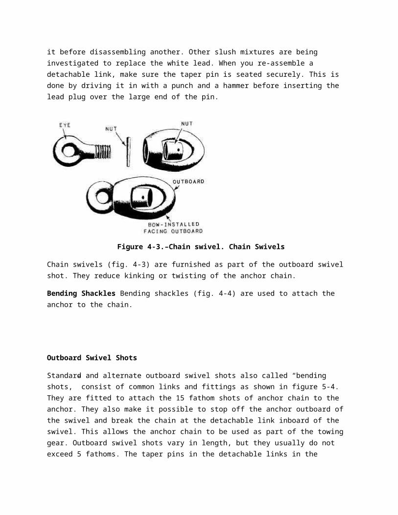
Figure 4-3.–Chain swivel. Chain Swivels
Chain swivels (fig. 4-3) are furnished as part of the outboard swivel shot. They reduce kinking or twisting of the anchor chain.
Bending Shackles Bending shackles (fig. 4-4) are used to attach the anchor to the chain.
Outboard Swivel Shots
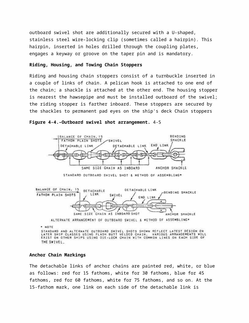
Standard and alternate outboard swivel shots also called “bending shots,” consist of common links and fittings as shown in figure 5-4. They are fitted to attach the 15 fathom shots of anchor chain to the anchor. They also make it possible to stop off the anchor outboard of the swivel and break the chain at the detachable link inboard of the swivel. This allows the anchor chain to be used as part of the towing gear. Outboard swivel shots vary in length, but they usually do not exceed 5 fathoms. The taper pins in the detachable links in the outboard swivel shot are additionally secured with a U-shaped, stainless steel wire-locking clip (sometimes called a hairpin). This hairpin, inserted in holes drilled through the coupling plates, engages a keyway or groove on the taper pin and is mandatory.
Riding, Housing, and Towing Chain Stoppers
Riding and housing chain stoppers consist of a turnbuckle inserted in a couple of links of chain. A pelican hook is attached to one end of the chain; a shackle is attached at the other end. The housing stopper is nearest the hawsepipe and must be installed outboard of the swivel; the riding stopper is farther inboard. These stoppers are secured by the shackles to permanent pad eyes on the ship's deck Chain stoppers
Figure 4-4.–Outboard swivel shot arrangement. 4-5
Anchor Chain Markings
The detachable links of anchor chains are painted red, white, or blue as follows: red for 15 fathoms, white for 30 fathoms, blue for 45 fathoms, red for 60 fathoms, white for 75 fathoms, and so on. At the 15-fathom mark, one link on each side of the detachable link is painted white, and one turn of wire is wrapped securely around each stud. At the 30-fathom mark, two links on each side of the detachable link
are painted white, and two turns of wire are wrapped around each of the last white studs. At 45 fathoms, three links on each side of the detachable link are painted white, and three turns of wire are wrapped around each of the last white studs.
At 60 fathoms, four links on each side of the detachable link are painted white, and four turns of wire are wrapped around each of the last white studs; and so on for each shot. Each link of the entire next-to-last shot is painted yellow. The last shot is entirely red. These last two shots give warning and danger signals of the approach of the bitter end of the anchor chain.
ANCHOR WINDLASS:
Windlasses are installed on board ships primarily for handling and securing the anchor and chain used for anchoring the ship and for handling anchor chain used for towing the ship. Most windlasses have capstans or gypsy heads for handling line in mooring and warping operations. Windlasses can be located on the stern of the ship for stern anchoring, but are usually located in the bow of the ship for handling bower anchors. These classes are electrohydraulic drive and electric drive. The essential parts of a typical windlass, regardless of its type and class, are the drive motor, wildcat, locking head, hand brake, capstan or gypsy head, and control. Horizontal shaft windlasses are usually made as a self-contained unit with the windlass and drive motor mounted on the same bedplate. Vertical shaft windlasses have their power source located below deck with only the wildcats and capstans mounted above deck. The windlass wildcat is a special type of drum or sprocket constructed to handle the anchor chain links. The outer surface has flats (or pockets) which engage chain links. At each end of the pockets, lugs (known as whelps) are provided, which contact the end of the flat link. A central groove in the outer surface accommodates the vertical links which are not in contact with the wildcat at any point. Windlass wildcats have a locking head for disengaging the wildcat from its power source. The locking head permits free rotation of the wildcat when you are “paying out” the chain. This brake may be used to hold the anchor and chain and to control the speed of descent when the anchor and chain are payed out. Capstan and gypsy heads fitted on windlasses are keyed to the drive shaft and rotate when the windlass power source is turning. When using the heads, apply the wildcat hand brake, then disengage the wildcat lock-ing head. The heads will now operate independently of the wildcats. When the wildcats are used, however, the capstan heads will always rotate.
Letting Go
When anchoring and weighing anchor, The Boatswain’s Mate in charge of the anchor detail musters the detail and makes sure all necessary gear is ready and available for use. The exact procedure may vary for making the anchor ready for letting go, but the following tasks must be performed.
The windlass is tested, the anchor in the hawse is freed, the anchor is walked out if anchoring is in deep water or if the bottom is rocky; the brake is set; and the wildcat is disengaged. All but one stopper is taken off and the anchor buoy line is shackled to the chafing chain or pendant.
The chain locker is checked for loose gear that may become wedged in the chain pipes or come flying out, endangering personnel on deck. An order then is given to stand clear of the chain. For obvious reasons, it is urgent that all hands obey this order! At the command “STAND BY” the brake is released and two Seamen-one with a sledgehammer or maul-take stations at the stopper outboard side of the chain.

When the command “LET GO” is given, one Seaman pulls the pin from the stopper tongue. The Seaman with the maul knocks the bail off the tongue of the pelican hook and steps clear. As soon as the Seaman is clear, the brake is fully released. If for some reason the stopper does not fall clear, the chain can still be controlled by the brake.
The Seaman tending the anchor buoy tosses it over the side and the jack is two-blocked (hoisted all the way up). On the signal bridge, the anchor ball is hoisted. The anchor buoy indicates the actual position of the anchor to which it is attached by floating above it.
The buoys are painted a distinctive color; green for the starboard anchor, red for the port anchor, and white for the stern anchor. If an anchor buoy floats on the surface, it is said to be “watching.” An anchor buoy may fail to watch be- cause its line is too short or the line is fouled in the chain.
Before anchoring, the line attaching the buoy to the anchor should be adjusted to a length that is a couple of fathoms greater than the depth of the water at anchorage. This extra length allows for slight fouling, tide variations, or the sinking of the anchor in mud, which might cause the actual depth to be greater than that shown on the navigational chart being used.
The anchor buoy and line must be laid up along, and outboard of, the lifelines. It should be put overboard, well clear of the ship the instant the anchor is let go.
On ships with power assist hand brakes, the power assist mechanism must be adjusted so when the brake is applied, the chain will not jump off the wildcat when it comes to a stop. An anchor buoy is a valuable time-saver in locating an anchor lost in weighing or one that is slipped in an emergency.
Slipping an anchor happens when un- expected circumstances do not permit time to weigh anchor. As soon as the anchor hits bottom the brake is set so the chain will not pile on it. As the ship gains sternway, the brake is released to lay the chain out evenly on the bottom and to control any running movement of the chain.
As each chain marking passes the wildcat, the report “(Number) SHACKLE ON DECK’ is made to the conning officer on the bridge. The direction the chain is tending is indicated by pointing the arm and/or reporting “CHAIN TENDING (number) O'CLOCK.” .
If the chain tends around the stem, the situation is reported to the bridge. The chain must be allowed to run freely or the sharp bend around the stem may damage a link. Detachable links are particularly susceptible to damage in this regard. If the anchor chain starts to get near the sonar dome, this situation is reported to the bridge, because anchor chain rubbing against the sonar dome can cause serious damage to it.
When the desired scope of chain is out, the conning officer gives the order “PASS THE STOPPERS.” The brake is set and the stoppers are applied and evened up, the brake is taken off, and the chain is slacked between the windlass and stopper. The brake is set, and the wildcat is left disengaged. Before securing, all gear is picked up and stowed.

Weighing Anchor
When you are weighing anchor, the same gear must be available on the forecastle as for anchoring. A hose is rigged to wash mud from the anchor and the chain. The windlass is energized and tested, and then the wildcat is engaged. The brake is then released and the wildcat is tested.
The brake is set, and all stoppers but one are cast off. When ready, the report “READY TO HEAVE IN” is made to the bridge. On the command “HEAVE AROUND,” the brake is taken off and the chain is heaved in enough to take the strain off the stopper.
The stopper is then cast off and heaving is resumed. Reports are made to the bridge periodically on the direction the chain is tending, the amount of chain remaining out, and the degree of strain on the chain.
If the command were “HEAVE AROUND TO SHORT STAY” the chain would be heaved in just short of breaking out the anchor (pulling the anchor loose from the bottom). When the chain is at short stay, it is reported to the bridge. On the command “HEAVE AROUND AND UP,” start heaving.
When the flukes have broken out, and the crown still rests on the bottom, the report “ANCHOR IS UP AND DOWN” is made. When the anchor is free of the bottom, it is said to be “AWEIGH” and is so reported. At this time the jack and anchor ball are hauled down and the ship is legally underway.
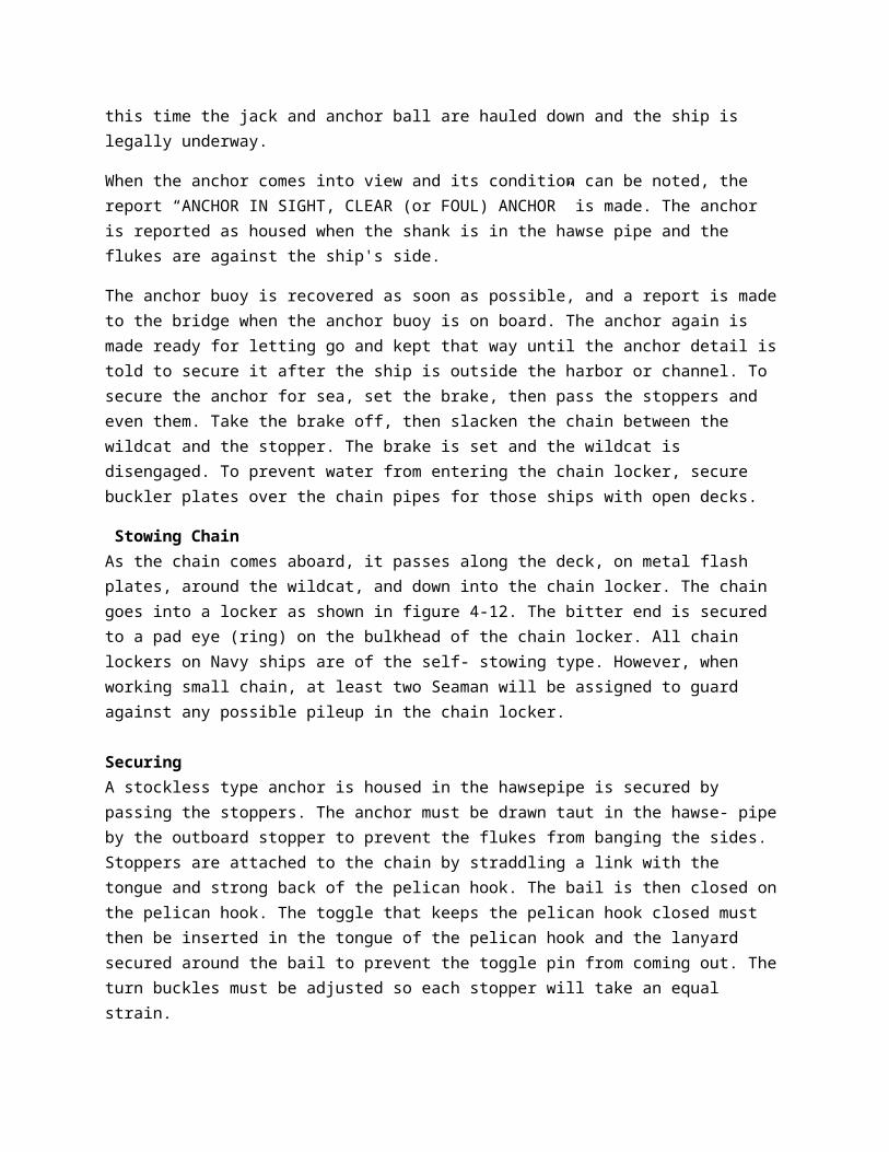
When the anchor comes into view and its condition can be noted, the report “ANCHOR IN SIGHT, CLEAR (or FOUL) ANCHOR” is made. The anchor is reported as housed when the shank is in the hawse pipe and the flukes are against the ship's side.
The anchor buoy is recovered as soon as possible, and a report is made to the bridge when the anchor buoy is on board. The anchor again is made ready for letting go and kept that way until the anchor detail is told to secure it after the ship is outside the harbor or channel. To secure the anchor for sea, set the brake, then pass the stoppers and even them. Take the brake off, then slacken the chain between the wildcat and the stopper. The brake is set and the wildcat is disengaged. To prevent water from entering the chain locker, secure buckler plates over the chain pipes for those ships with open decks.
Stowing Chain As the chain comes aboard, it passes along the deck, on metal flash plates, around the wildcat, and down into the chain locker. The chain goes into a locker as shown in figure 4-12. The bitter end is secured to a pad eye (ring) on the bulkhead of the chain locker. All chain lockers on Navy ships are of the self- stowing type. However, when working small chain, at least two Seaman will be assigned to guard against any possible pileup in the chain locker.
Securing A stockless type anchor is housed in the hawsepipe is secured by passing the stoppers. The anchor must be drawn taut in the hawse- pipe by the outboard stopper to prevent the flukes from banging the sides. Stoppers are attached to the chain by straddling a link with the tongue and strong back of the pelican hook. The bail is then closed on the pelican hook. The toggle that keeps the pelican hook closed must then be inserted in the tongue of the pelican hook and the lanyard secured around the bail to prevent the toggle pin from coming out. The turn buckles must be adjusted so each stopper will take an equal strain. Figure 4-12.–Stowage of chain. 4-11
CAPSTANS :Capstans are mounted on deck to ease the handling of large, heavy mooring lines and wires. These capstans may be separate machinery units or part of the anchor windlass. The capstan's spool-shaped drum keeps the lines from slipping, especially when wet. Most capstans are electrically driven. Depending on the class of ship and its size, capstans may be located any place on the deck, but they are usually found on the forecastle and fantail.
Moorings:A vessel can be made fast to any variety of shore fixtures from trees and rocks to specially constructed areas such as piers and quays. The word pier is used in the following explanation in a generic sense. Mooring is often accomplished using thick ropes called mooring lines or hawsers. The lines are fixed to deck fittings on the vessel at one end, and fittings on the shore, such as bollards, rings, or cleats, on the other end.
Mooring requires cooperation between people on the pier and on a vessel. For larger vessels, heavy mooring lines are often passed to the people on the shore by use of smaller, weighted heaving lines. Once the mooring line is attached to the bollard, it is pulled tight. On large ships, this tightening can be accomplished with the help of heavy machinery called mooring winches or capstans.
For the heaviest cargo ships, more than a dozen mooring lines can be required. Small vessels generally take 4 to 6 mooring lines.
Mooring lines are usually made out of synthetic materials such as nylon. Nylon is easy to work with and lasts for years, but has a property of very great elasticity. This elasticity has its advantages and disadvantages. The main advantage is that during an event, such as a high wind or the close passing of another ship, excess stress can be spread among several lines On the other hand, if a highlystressed nylon line does break, or part, it causes a very dangerous phenomenon called "snapback" which can cause fatal injuries. Snapback is analogous to stretching a rubber band to its breaking point between the hands, and then suffering a stinging blow from the retracting loose ends of the band - in the case of a heavy mooring line this blow carries much more force and can inflict severe injuries or sever limbs. Mooring lines made from materials
such as Dyneema and Kevlar have much less elasticity and therefore much safer to use, but the lines do not float on the water, and tend to sink, are costly, so they are used less frequently. Manila rope is preferred. Some ships use wire rope for one or more of their mooring lines. Wire rope is hard to handle and maintain. There is also a risk of using wire rope on a ship's stern in the vicinity of its propeller.
Combination mooring lines made of both wire rope and synthetic line can also be used. This results in a hawser. This is more elastic and easier to handle than a wire rope, but not as elastic as a pure synthetic line. Special safety precautions must be followed when constructing a combination mooring line.
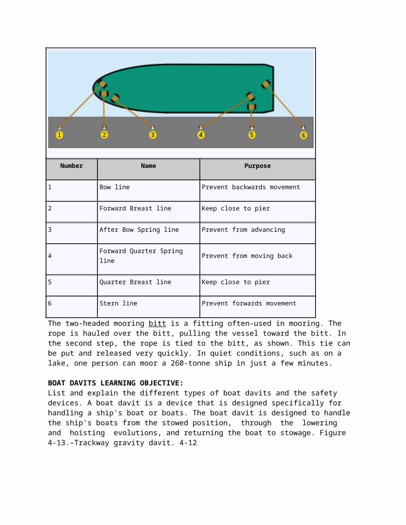
A typical mooring scheme
Number Name Purpose
1 Bow line Prevent backwards movement
2 Forward Breast line Keep close to pier
3 After Bow Spring line Prevent from advancing
4 Forward Quarter Spring line Prevent from moving back
5 Quarter Breast line Keep close to pier
6 Stern line Prevent forwards movement
The two-headed mooring bitt is a fitting often-used in mooring. The rope is hauled over the bitt, pulling the vessel toward the bitt. In the second step, the rope is tied to the bitt, as shown. This tie can be put and released very quickly. In quiet conditions, such as on a lake, one person can moor a 260-tonne ship in just a few minutes.
BOAT DAVITS LEARNING OBJECTIVE:
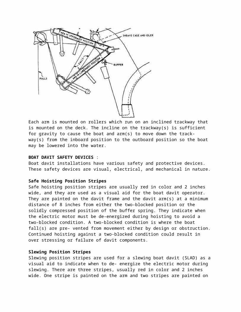
List and explain the different types of boat davits and the safety devices. A boat davit is a device that is designed specifically for handling a ship's boat or boats. The boat davit is designed to handle the ship's boats from the stowed position, through the lowering and hoisting evolutions, and returning the boat to stowage. Figure 4-13.–Trackway gravity davit. 4-12
Each arm is mounted on rollers which run on an inclined trackway that is mounted on the deck. The incline on the trackway(s) is sufficient for gravity to cause the boat and arm(s) to move down the track- way(s) from the inboard position to the outboard position so the boat may be lowered into the water.
BOAT DAVIT SAFETY DEVICES :Boat davit installations have various safety and protective devices. These safety devices are visual, electrical, and mechanical in nature.
Safe Hoisting Position Stripes Safe hoisting position stripes are usually red in color and 2 inches wide, and they are used as a visual aid for the boat davit operator. They are painted on the davit frame and the davit arm(s) at a minimum distance of 8 inches from either the two-blocked position or the solidly compressed position of the buffer spring. They indicate when the electric motor must be de-energized during hoisting to avoid a two-blocked condition. A two-blocked condition is where the boat fall(s) are pre- vented from movement either by design or obstruction. Continued hoisting against a two-blocked condition could result in over stressing or failure of davit components.
Slewing Position Stripes Slewing position stripes are used for a slewing boat davit (SLAD) as a visual aid to indicate when to de- energize the electric motor during slewing. There are three stripes, usually red in color and 2 inches wide. One stripe is painted on the arm and two stripes are painted on the pedestal. One of the two pedestal stripes in- dicates when the arm is slewed to the STOW position and the other indicates when the arm is slewed to the LOWERING position.
Emergency Disconnect Switch

The emergency disconnect switch is located at the boat davit operation station to allow the operator to interrupt power to the motor. It is used in an emergency situation to prevent a two-blocked condition if another control component fails to function properly.
Double Break Feature Electrical contacts subjected to momentary jogging service are prone to sticking or welding. This can cause uncontrolled operation of the winch. The double break feature is the arrangement of two independent contactors in the supply leads to protect against this danger. When the motor power supply is interrupted by the master switch the supply leads are opened in two places by contactors which are not interlocked.
MOORING PARTS:
CLEATS A device consisting of a double-ended pair of projecting horns used for belaying a line or wire.
BITTSBitts are heavy vertical cylinders, usually arranged in pairs, used for making fast lines that have been led through chocks. The upper end of a bitt is either larger than the lower end or is fitted with a lip to keep lines from slipping off accidentally. As bitts are required to take very heavy loads, extra frames are worked into their foundations to distribute the strain. Usually there is a set of bitts forward and aft of each chock When constructed in pairs, each bitt is sometimes called a barrel.
CHOCKS A chock is a heavy fitting with smooth surfaces through which mooring lines are led. Mooring lines are run from bitts on deck through chocks to bollards on a pier when the ship is moored. There are three types of chocks: An open chock is a mooring chock that is open at the top. A closed chock is a mooring chock, closed by an arch of metal across the top. A roller chock is a mooring chock that contains a roller for reducing friction.
PAD EYESA pad eye is a plate with an eye attached, welded to the deck to distribute the strain over a large area and to which a block can be hooked or shackled. A pad eye is also used in towing operations.
BOLLARDS A bollard is a strong cylindrical upright on a pier, over which the eye (or bight) of a ship’s mooring line is placed.
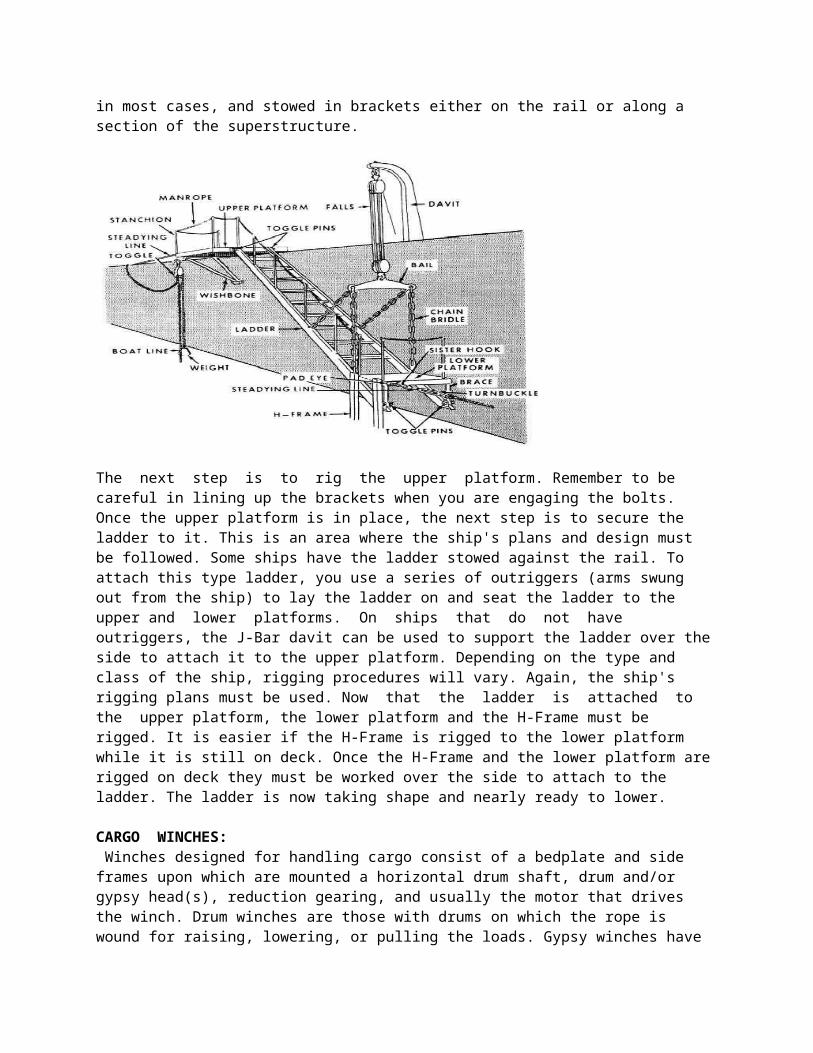
ACCOMODATION LADDERS: Ships are fitted with accommodation ladders that can be rigged and lowered over the side. These ladders provide a convenient means for boarding or leaving an anchored vessel. Some accommodation ladders can be modified for use on a pier or barge. Large. If more than one ladder is rigged, the forward accommodation ladder is the quarterdeck and reserved for officers and ceremonies. The after ladder is used by work details and crew liberty parties. The accommodation ladder, figure 4-18, has an upper and lower platform that is connected by the ladder and supported by either a chain or wire bridle and bail hanging by a pendant. Another method is the use of a metal bail shaped like an elongated upside down letter U which holds the ladder by a pendant rigged to the side of the ship or from a J-Bar davit. The lower platform of the accommodation ladder has additional parts that must be rigged. An H-Frame equipped with fenders is rigged to the outboard side of the lower platform. This H-Frame is where boats can come alongside to pick up or discharge passengers. The inboard side of the lower platform is fitted with ports called shoes, that when rigged hold the ladder in the proper position off the side of the ship.

The shoes have pads attached to their ends to help prevent damage to the ship or the ladder. The lower platform also has turnbuckles, and in some cases, pendants to restrict the fore and aft movement of the ladder. The upper platform is supported by a brace known as a wishbone. A single-sheave block is attached to the underside of the forward outboard comer of the upper platform. A line is rigged through this block which acts as a sea painter to keep a boat alongside in position with the accommodation ladder. A toggle between the strands of the line prevents the line from running up into the block and becoming inaccessible to a boat. There may be some accommodation ladders made of steel still in service, but for ease of handling, it has changed to aluminum. When an accommodation ladder is secured for sea, everything is rigged in, disassembled in most cases, and stowed in brackets either on the rail or along a section of the superstructure.
The next step is to rig the upper platform. Remember to be careful in lining up the brackets when you are engaging the bolts. Once the upper platform is in place, the next step is to secure the ladder to it. This is an area where the ship's plans and design must be followed. Some ships have the ladder stowed against the rail. To attach this type ladder, you use a series of outriggers (arms swung out from the ship) to lay the ladder on and seat the ladder to the upper and lower platforms. On ships that do not have outriggers, the J-Bar davit can be used to support the ladder over the side to attach it to the upper platform. Depending on the type and class of the ship, rigging procedures will vary. Again, the ship's rigging plans must be used. Now that the ladder is attached to the upper platform, the lower platform and the H-Frame must be rigged. It is easier if the H-Frame is rigged to the lower platform while it is still on deck. Once the H-Frame and the lower platform are rigged on deck they must be worked over the side to attach to the ladder. The ladder is now taking shape and nearly ready to lower.
CARGO WINCHES: Winches designed for handling cargo consist of a bedplate and side frames upon which are mounted a horizontal drum shaft, drum and/or gypsy head(s), reduction gearing, and usually the motor that drives the winch. Drum winches are those with drums on which the rope is wound for raising, lowering, or pulling the loads. Gypsy winches have one or two horizontally mounted gypsy heads around which turns of line can be taken. Combination winches are drum winches with shafts extended to take gypsy heads on either side or on both sides. Preceding every winch operation, operators should review all general operating and safety instructions, among which are the following:
1. Always inspect the area around the winch, and make sure there is a dry, safe place for the winch operator to stand. 2. Inspect the rigging, making certain that the standing rigging is taut and that the running rigging is not fouled. 3. Inspect the equipment, making sure the clutch levers are locked in place. Although the engineering department is responsible for maintaining winches, the winch operator and the Chief officer in charge must make certain that the required maintenance is actually performed. Coordination is essential for good winch operation. After sufficient practice, winch operators should be able to pick a draft from the hold and deposit it on the pier in one smooth, constant motion.
When cargo is being hoisted or lowered, swinging should be avoided if possible. A wildly swinging draft often results in damaged cargo and endangers the lives of personnel working in the hold, on deck, or on the pier. Swinging can usually be prevented in the hold or on the pier by dragging or touching the draft until it is directly under the head of the boom before hoisting. Occasionally, a draft will start to swing athwartships while being carried across the deck This swinging must be stopped before the load can be landed. It can be done easily with a little practice.
BOATSWAIN'S CHAIR :The boatswain's chair is a hardwood seat attached to a double bridle of stout line, as shown in figure 4-29. It is always bent to the gantline by a double becket. A length of slack end is left hanging, as shown, for use in securing to masts or stays aloft. For a straight drop, as when painting down a mast, rig the chair for self-lowering. When you are coming down a mast, you will often find that the ladder takes you only to the crosstree. You must be hoisted from there to the truck by personnel on deck. When there is no way of getting to the truck by ladder, a dummy gantline usually is left reeved from the crosstree up through the sheave at the truck and back to the crosstree. The dummy gantline makes it unnecessary for anyone to climb the topmast to reeve a chair gantline through. You must never let the end get away from you and reeve out.
WORKING OVER THE SIDE:
Figure 4-31.–Rigging for self-lowering. jackets. Except for personnel in boats, personnel working over the side must be equipped with a parachute-type safety harness with safety lines tended from the deck above. All personnel should be instructed in all applicable safety regulations before they are permitted to work over the side of the ship on scaffolding, stages, or in boatswain's chairs. A competent officer must constantly supervise personnel working on scaffolding, stages, and in
boatswain's chairs, and personnel must be assigned to tend the safety lines. When personnel are doing hot-work such as welding or cutting while working over-the-side or aloft, fiber lines could burn and cause a serious mishap. To prevent this, replace all personnel safety lines and the fiber lines on the staging and boatswain chairs with wire rope. All tools, buckets, paint pots, and brushes used by personnel working over the side of the ship should be secured by lanyards to prevent their loss overboard or injury to personnel below. STAGE The stage is a stout plank to the underside of which two short wooden horns are attached athwartships, either by nailing or bolting on, a foot or two from either end. When the stage is rigged properly, all the weight comes on the plank. The chief purpose of the horns is to hold the plank off the side. The gantlines on your stage may be rigged in one of two ways. The first is by an eye splice in the end of the 4-39
Be sure to pass the part between the half hitches under the plank. If you pass it over, there will be nothing holding you up but the horns. The second method of rigging the stage is by the stage hitch. This method is the better of the two because there are two parts of the gantline under the plank instead of one, and there is no need to eye splice the end.
TAKING SOUNDING:Soundings (measuring the depth of water) are taken when the ship is going into or out of port or approaching an anchorage. The hand lead is the most accurate means for obtaining soundings. It is used in shallow water and when the speed of the ship is slow. Even though ships today have modem depth-sounding equipment, lead- lines are a mandatory piece of equipment and are routinely inspected during inspections and refresher training periods.
LEAD LINE :The leadline or hand lead consists of a narrow block of lead weighing from 7 to 14 pounds, which is attached to a marked line. With the ship making 12 knots, a good leadsman can get reliable soundings down to 7 fathoms. At slower speeds, of course, the lead has time to sink even deeper before the ship moves up to it. The leadline may also be used for determining the direction in which a ship, practically dead in the water, is moving. Direction of movement is found by placing the lead on the bottom, directly below the leadsman, and noting the direction of the motion of the ship as shown by the change of direction of the leadline from the up and down. Before heaving, the leadsman takes station in the chains, which usually are platforms projecting over each side at the after end of the forecastle. The lead is then lowered over the side and is supported in the heaving hand by a wooden toggle, inserted in the lead line about 2 fathoms from the lead. The spare line is coiled in the other hand, free for running. To make the heave, start by calling out “WATCH- ON-WATCH” then swing the lead in a fore-and-aft direction outboard of the chains to gain momentum. Then swing the lead in a complete circle. When the force is great enough, let go the lead as it swings for- ward at a point about level with the deck. As the ship moves ahead, heave in the spare line rapidly. The marker should be read when the lead is on the bottom and the line hauled just taut, up and down. The ability to heave the lead can be acquired only by practice. It is necessary to practice with both hands because the right hand is used for heaving from the starboard chain; the left hand for heaving from the port chain. A good heave has no value unless the depth can be read correctly and quickly. Leadlines often are marked at each half fathom over the range of depth used most and may even have foot markings around the more important depths.
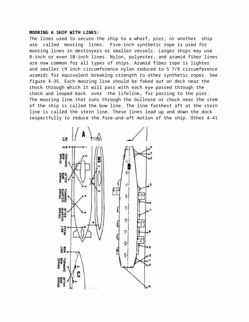
MOORING A SHIP WITH LINES: The lines used to secure the ship to a wharf, pier, or another ship are called mooring lines. Five-inch synthetic rope is used for mooring lines in destroyers or smaller vessels. Larger ships may use 8-inch or even 10-inch lines. Nylon, polyester, and aramid fiber lines are now common for all types of ships. Aramid fiber rope is lighter and smaller (9 inch circumference nylon reduced to 5 7/8 circumference aramid) for equivalent breaking strength to other synthetic ropes. See figure 4-35. Each mooring line should be faked out on deck near the chock through which it will pass with each eye passed through the

chock and looped back over the lifeline, for passing to the pier. The mooring line that runs through the bullnose or chock near the stem of the ship is called the bow line. The line farthest aft at the stern line is called the stern line. These lines lead up and down the dock respectfully to reduce the fore-and-aft motion of the ship. Other 4-41
From Structural Steel Designer's HandBook: AISC, AASHTO, AISI, ASTM, AREMA, and ASCE-07 Design Standards, Fourth Edition
12.8 EXAMPLE ALLOWABLE STRESS DESIGN OF DECK PLATE-GIRDER BRIDGE WITH FLOORBEAMS
Two simply supported, welded, deck plate girders carry the four lanes of a highway bridge on a 137.5-ft span. The girders are spaced 35 ft c to c. Loads are distributed to the girders by longitudinal stringers and floorbeams (Fig. 12.22). The typical cross section in Fig. 12.23 shows a 48-ft roadway flanked by 3-ft-wide safety walks. Grade 50 steel is to be used for the girders and Grade 36 for stringers, floorbeams, and
other components. Concrete to be used for the deck is class A, with 28-day strength = 4000 psi and allowable compressive stress f c = 1400 psi. Appropriate design criteria given in Chap. 10 will be used for this structure.
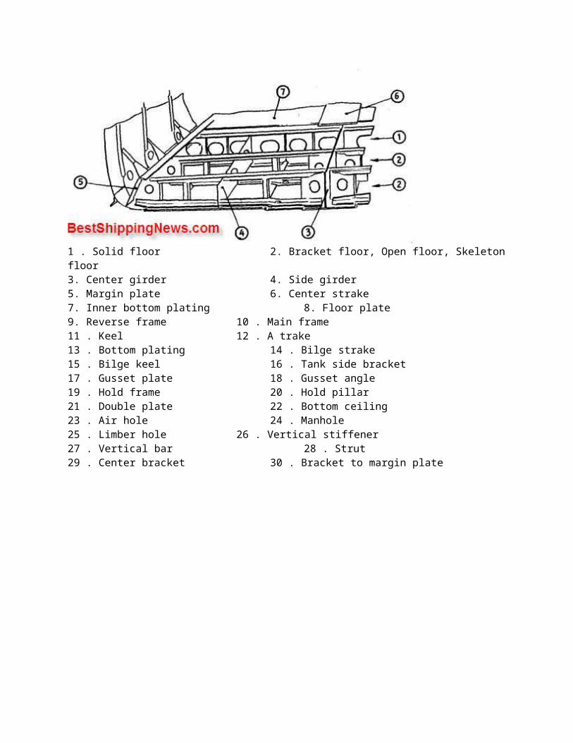
1 . Solid floor 2. Bracket floor, Open floor, Skeleton floor3. Center girder 4. Side girder5. Margin plate 6. Center strake7. Inner bottom plating 8. Floor plate9. Reverse frame 10 . Main frame11 . Keel 12 . A trake13 . Bottom plating 14 . Bilge strake15 . Bilge keel 16 . Tank side bracket17 . Gusset plate 18 . Gusset angle19 . Hold frame 20 . Hold pillar21 . Double plate 22 . Bottom ceiling23 . Air hole 24 . Manhole25 . Limber hole 26 . Vertical stiffener27 . Vertical bar 28 . Strut29 . Center bracket 30 . Bracket to margin plate
31 . Lightening hole
Definitions of hull elements
Keel: The keel is a member, or series of members, running longitudinally that forms the structural base of a ship. The keel always corresponds to a ship's centreline. It is a major component in providing longitudinal strength and efficiently distributes local stresses when the ship is dry docked. There are two types of keels used to build ships of a certain size, the flat keel and the duct keel.
Flat keel
Duct keel

Girders: A girder is a longitudinal member used in the construction of the bottom of a ship. They can be solid or not and can be placed above the keel (centre girder) or spaced equal distances from it (side girders). They can be continuous or divided by floor sections (intercostal side girders). The centre girder is always one continuous piece and must be fastened to the keel with a continuous weld. Girders must extend as far as possible from the forward to the aft end of a ship.
Floors: These are made up of cross members that are mounted perpendicular to the keel and girders. There are three main types of floor: solid, plate and bracket.
Plate floor
Solid floor

Bracket or open floor
Frames: These are vertical members that make up the framing of the vertical part of the hull. Frame type and spacing vary considerably depending on the ship's construction.
Shell framing
Deck beams: These are transverse members that connect the top ends of the frames, forming the transverse framing for the deck.
Longitudinal framing, deck and shell
Deck girders: These are longitudinal members that combine with the beams to form the longitudinal framing of the deck.
Longitudinals: A very general term to identify any small longitudinal member that can be used for several purposes. This term is used more specifically in longitudinal framing.
Web frames: Oversized members that replace a frame at certain locations on a ship. Bracket: A general term that identifies any part used to connect two members. Beam knee: Bracket located at the end of deck beams that connect the beam and frame to the
shell plating. Pillar: Vertical member inside a ship that connects the deck to the ship's bottom, where it is
installed between two tweendecks, especially around hatches. They are quite bulky and complicate cargo handling inside holds.
Plating: The plating of a hull is the series of plates that form the watertight shell of the hull. There is bottom plating, deck plating and side shell plating.
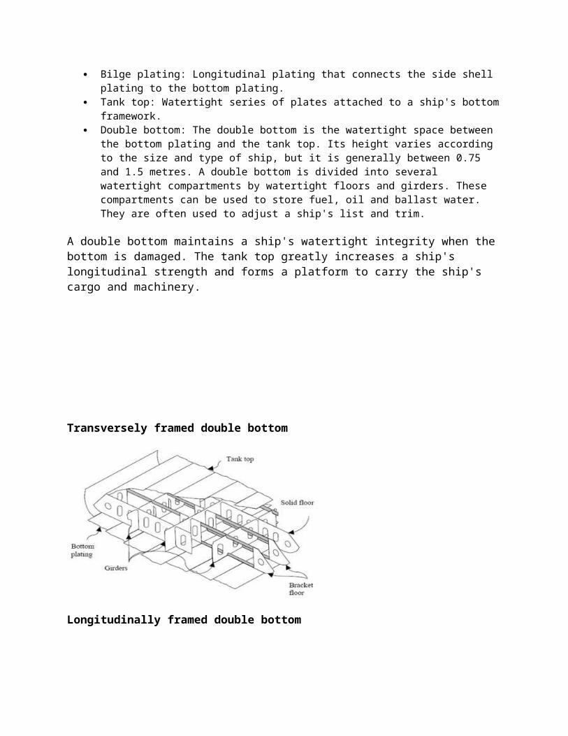
Bilge plating: Longitudinal plating that connects the side shell plating to the bottom plating. Tank top: Watertight series of plates attached to a ship's bottom framework. Double bottom: The double bottom is the watertight space between the bottom plating and the
tank top. Its height varies according to the size and type of ship, but it is generally between 0.75 and 1.5 metres. A double bottom is divided into several watertight compartments by watertight floors and girders. These compartments can be used to store fuel, oil and ballast water. They are often used to adjust a ship's list and trim.
A double bottom maintains a ship's watertight integrity when the bottom is damaged. The tank top greatly increases a ship's longitudinal strength and forms a platform to carry the ship's cargo and machinery.
Transversely framed double bottom
Longitudinally framed double bottom
Transverse framing
Transverse framing is used primarily for ships less than 120 metres in length. The floors, frames and beams form rings spaced closely together. Longitudinal strength is provided by the keel, centre girder, side girders, deck girders, the entire bottom, deck and side shell plating, and the tank top. Transverse framing ensures good cross sectional strength to handle overall stresses, vertical loads, rolling and dry docking. However, on very long ships, sheer stresses can cause deformations between the rings.
Longitudinal framing Longitudinal framing is mandatory for very large ships, oil tankers and bulk-ore carriers. The rings are formed of floors, deck beams and web frames that replace the frames. These rings are farther apart than in transverse framing. The longitudinal reinforcement members are deck girders, girders, the keel and a large number of deck, bottom and side longitudinals. The longitudinals are slender but there are very many of them.

Mixed framing
Mixed framing combines longitudinal and transverse framing. One type of framing is used in one part of the ship and the other type is used in another part. The most common combination is longitudinal framing for the bottoms and the deck, and transverse framing for the sides.
DOUBLE BOTTOM TANK:
The present invention relates to a rebuilt double hull tanker and a method of rebuilding an existing single hull tanker into a rebuilt double hull tanker. The rebuilt double hull tanker includes a rebuilt double hull comprising a new double bottom hull and new double side hulls. The internally rebuilt double bottom hull includes the existing outer bottom hull and a new inner bottom hull that is disposed internal and spaced apart from the existing outer bottom hull. The externally rebuilt double side hulls (e.g., port and starboard) include the existing inner side hulls and new outer side hulls disposed external and spaced apart from the existing inner side hull. The rebuilt double bottom hull is connected at each end (e.g., at the turn of the bilge) to the rebuilt double side hulls. The method includes forming the new double hull, including a new double bottom hull and new double side hulls, over at least the cargo carrying portion of the tanker by installing the new inner bottom hull internally over the existing outer bottom hull through access holes cut into the sides of the tanker and installing the new double side hulls externally over the existing inner side hulls.
Shearing Force
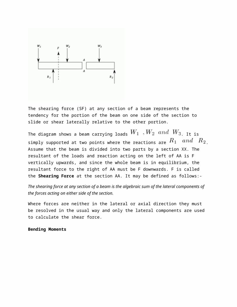
The shearing force (SF) at any section of a beam represents the tendency for the portion of the beam on one side of the section to slide or shear laterally relative to the other portion.
The diagram shows a beam carrying loads . It is simply supported at two
points where the reactions are . Assume that the beam is divided into two parts by a section XX. The resultant of the loads and reaction acting on the left of AA is F vertically upwards, and since the whole beam is in equilibrium, the resultant force to the right of AA must be F downwards. F is called the Shearing Force at the section AA. It may be defined as follows:-
The shearing force at any section of a beam is the algebraic sum of the lateral components of the forces acting on either side of the section.
Where forces are neither in the lateral or axial direction they must be resolved in the usual way and only the lateral components are used to calculate the shear force.
Bending Moments
In a similar manner it can be seen that if the Bending moments (BM) of the forces to the left of AA are clockwise, then the bending moment of the forces to the right of AA must be anticlockwise.
Bending Moment at AA is defined as the algebraic sum of the moments about the section of all forces acting on either side of the section.
Bending moments are considered positive when the moment on the left portion is clockwise and on the right anticlockwise. This is referred to as a sagging bending moment as it tends to make the beam concave upwards at AA. A negative bending moment is termed hogging.
APPENDIX A (Revision 1 07/07/2011)UNOLS Rope and Cable Safe Working Load Standards ROPE: A woven, flexible tension member with no internal conductors. It may be made from natural fibers, synthetic fibers, or metal.

CABLE: A woven, flexible tension member with internal conductors or other means of transmitting data such as glass fiber. TENSION MEMBER: Generic name used to describe a rope or cable in service for over the side work. ELASTIC LIMIT: The elastic limit or yield point of a material is the stress at which a material begins to deform plastically. Prior to the yield point the material will deform elastically and will return to its original shape when the applied stress is removed. Once the yield point is passed some fraction of the deformation will be permanent and non-reversible. For rope or cable this is the load that causes permanent set, or deformation, of the wires. TRANSIENT LOADS: Loads induced which are temporary by nature, including the weight of entrained mud, weight of entrained water, pull out loads, drag due to package characteristics and/or winch speed, etc. DYNAMIC LOADS: Loads induced due to vessel motion (heave, roll, pitch, etc.) TESTED BREAKING LOAD (TBL): The actual load required to pull a tension member to destruction as determined by testing. Depending on the intended use of the tension member testing may need to be done under fixed end and free to rotate conditions.ASSIGNED BREAKING LOAD (ABL): Will be the lowest of the Nominal Breaking Load and Tested Breaking Load. In practice ABL will be equal to NBL used unless testing shows TBL to be less than NBL. An ABL that is greater than the NBL may never be used. Depending on the intended use of the tension member there may be two ABLs for fixed end and free to rotate conditions. SAFE WORKING LOAD (SWL): The maximum tension that is allowed to be applied to the tension member during normal operation. FACTOR OF SAFETY (FS): For the purpose of this document defined as Assigned Breaking Load / Safe Working Load. SWL = ABL / FSFor the purposes of this standard, FS shall be considered the value selected by the operator. Because there may be two different ABLs (fixed end & free to rotate) there may be two SWLs. Section 6.0 defines the minimum standards that must be met to select specific FS values. INSPECTION, TESTING AND PREVENTATIVE REQUIREMENTS Cable paths and fairlead arrangements vary widely from ship to ship and change over both the short term (from cruise to cruise) and the life of the vessel. It is impossible to develop a set of standards, which tries to quantify the precise effects on breaking strength, or tension member life, as a result of system design. Instead, each vessel must have a testing program in place, which suits how their tension members are used, and routinely evaluates the status of each. The assumption is that the results of testing will indicate the effect of both the loading and system design on the breaking strength of the tension member. The testing program followed shall be based on the FS selected by the Owner, which is in turn based on use and the particulars of the handling system employed. The Owner shall have documentation in place specifying the FS for each tension member in use.Tension member test samples shall be a clean, “representative” length from the end that will be put into future use, not simply the end immediately adjacent to the existing termination. Although this may not be

the location of maximum loading during operations, this represents a practical means of determining ABL from an operational standpoint. The initial ABL shall be assigned through testing by the UNOLS Wire Pool before distribution to the fleet. If the initial test results in an ABL less than the NBL, the Wire Pool shall reject the tension member. If subsequent testing results in a TBL that is greater than or equal to the initial ABL, the initial ABL shall be used by the Vessel Operation for the purposes of this standard.
The Vessel Operator shall also provide a copy of the wire history or wire log information with the sample and, as a minimum, this should include the following: •UNOLS wire identifier, as described in Chapter 7 UNOLS Winch and Wire Handbook, Third Edition•Winch and system manufacturer.•Number and/or duration of deployments since last test.•Maximum tension of each deployment.•Maximum payout of each deployment.•Description of wire train: the number of sheaves between winch and water. Sheave material and values of “D” and “w” for each sheave.
Stresses and constraints on ship structure
Static stresses and constraints
These stresses are measured when the ship is not under way. They are often caused by a poor longitudinal distribution of mass. Even if the ship's total weight is balanced by the total force of buoyancy, these forces may not be distributed evenly along the full length of the ship.
Hogging: If the forces of buoyancy are concentrated around the section amidships and the ends are loaded, the ship will tend to move downwards at the bow and stern while the section amidships will tend to move upwards. In this situation, the deck's structural members are being subjected to tensile stress while the bottom structure is under compressive stress. This phenomenon can be compared to a beam supported in the centre and loaded with weights on the ends.
Hogging

Sagging: If the forces of buoyancy are concentrated under the bow and stern of the ship and the section amidships is loaded, the ship will tend to move upwards at the ends and trough amidships. In this situation, the deck's structural members are under compressive stress while the bottom structure is being subjected to tensile stress. This phenomenon can be compared to a beam that is supported at both ends and loaded with weights in the middle.
Hogging and sagging can be amplified by the movement of waves passing along the hull. A crest of waves at each end of a ship combined with a trough amidships will amplify sagging, while a crest amidships combined with a trough at both ends will amplify hogging.
The stresses caused by these situations can be calculated using the load curves table, the stress and sheer curves table, and the bending moments table. Manual or electronic calculators also exist to find the value of the stresses on the hull. The maximum permissible stress values can be found in the ship's stability book.
Dynamic stresses and constraints
When a ship is under way, some situations create additional stresses. They are caused primarily by the effect of waves on the hull in rough seas. Two of these are pounding and panting.
Pounding: When a ship sails in heavy seas, it pitches. It can happen that the bow rises over the crest of a wave and emerges completely out of the water. When the bow comes back down on the water, it can be subjected to a major impact, which is pounding. The hull plating at the bow end of the ship must be reinforced to avoid bending of the plating. This stress can also occur at the ship's stern, but to a lesser degree.
Panting: When waves hit the bow and stern of a ship, they create variations in pressure that tend to push the plating in and out. This is panting. The framing at the ship's ends must be reinforced to prevent exaggerated movement of the hull plating.
Watertight bulkheads :
A watertight bulkhead is a transverse bulkhead mounted on the tank top and it must extend right to the uppermost continuous deck. Watertight bulkheads are installed to:

Divide the ship into watertight compartments and thereby limit flooding if the hull plating is damaged;
Improve the transverse strength of the structure; Prevent distortion of the hull plating; Support the deck girders and longitudinals; Rigidly attach the tank top to the upper deck; Greatly slow the spread of fire.
The number and location of watertight bulkheads on a ship depend on the length and type of ship and the location of the machinery space. The SOLAS Convention determines the number and location of these bulkheads. But in general, there is a watertight bulkhead (collision bulkhead) at the bow that should be located between 0.05L and 0.075L (L = length between perpendiculars of a ship), a watertight bulkhead at the stern that should form a watertight aft compartment (after peak) that encloses the stern tube, and a watertight bulkhead at each end of the machinery space (where the aft bulkhead may be the after-peak bulkhead).
All members that pass through a watertight bulkhead, such as ventilation ducts, piping and electric wiring, must be mounted so as to maintain the watertight integrity of the bulkhead. That is why remote controlled stopcocks are generally found on certain pipes that pass through watertight bulkheads.
Watertight doors:
In some situations, it is necessary to pierce bulkheads to allow crew or passengers through. In this case, a sliding watertight door is installed. An example of this situation is the watertight door that is found on some ships between the machinery space and the shaft tunnel. Liners have many of these doors that allow passengers to go between the different sections of the ship. These watertight doors are usually hydraulically activated. Local control stations must be located on either side of the door. In addition, a remote control station (generally located in the wheelhouse) must be placed outside both compartments separated by the watertight bulkhead.
Chapter II-1, Regulation 15 of the SOLAS Convention governs the installation and operating requirements for these doors.
Extract, Regulation 15,
7.1.6: [A watertight door] shall be provided with an audible alarm, distinct from any other alarm in the area, which will sound whenever the door is closed remotely by power and which shall sound for at least 5 s but no more than 10 s before the door begins to move and shall continue sounding until the door is completely closed. In the case of remote hand operation it is sufficient for the audible alarm to sound only when the door is moving. Additionally, in passenger areas and areas of high ambient noise the Administration may require the audible alarm to be supplemented by an intermittent visual signal at the door; and
7.1.7: shall have an approximately uniform rate of closure under power. The closure time, from the time the door begins to move to the time it reaches the completely closed position, shall in no case be less than 20 s or more than 40 s with the ship in the upright position.
Watertight bulkhead
LOAD LINE SURVEYS: All ships must be issued with a load line certificate. The form of the certificate willdepend upon the Assigning Authority as follows:* If the certificate is an “International Load Line Certificate”it shall be in the form prescribed by the 1966 Convention which is detailed in the IMO publication ‘Load Lines – 2002 Edition’ M. S. (Load Line) Regulations1998 it shall be in the form prescribed in Schedule 8 of MSN 1752(M). Initial survey : before the ship is put into service;* Renewal survey : at intervals not exceeding five years;* Annual survey : within 3 months either way of the anniversary date of the load line certificate. The surveyor will endorse the load line certificate on satisfactory completion of the annual survey. The period of validity of the load line certificate may be extended for a period not exceeding 5 months if:(a) the load line certificate is still in force(b) the ship has been subjected to a renewal survey and complies with the requirements of the M.S. (Load Line) Regulations 1998, and(c) it is not reasonably practicable to issue a new certificate before the expiry date of the current certificate.
Survey preparation The preparation for a load line survey will involve ensuring that the hull is watertight below the freeboard deck and weather tight above it (cargo tank lids on tankers must be watertight).
The following checks should be conducted prior to survey:(1) Check that all access openings at the ends of enclosed superstructures are in good condition.

All dogs, clamps and hinges should be free and greased. Gaskets and other sealing arrangements should not show signs of perishing (cracked rubbers). Ensure that doors can be opened from both sides. Ensure that door labels such as ‘ To be kept closed at sea’ are in place.(2) Check all cargo hatches and accesses to holds for weather tightness. Securing devices such as clamps, cleats and wedges are to be all in place, well greased and adjusted to provide optimum sealing between the hatch cover and compression bar on the coaming. Replace perished rubber seals as necessary. Hose test hatches to verify weather tightness.(3) Check the efficiency and securing of portable beams. Load Line Surveys (MAR Rev. 05/06/03) 1. (4) For wooden hatches, ensure that the hatch boards are in good condition and that the steel binding bands are well secured. A minimum of at least two tarpaulins should be provided at each hatch, which must be in good condition, waterproof and of a strong approved material. Locking bars and side wedges must be in place and be in good order.(5) Inspect all machinery space openings on exposed decks.(6) Check that manhole covers on the freeboard deck are capable of being made watertight.(7) Check that all ventilator openings are provided with an efficient weather tight closing appliances. If applicable, ventilator plugs and canvas covers must be available and in good order.(8) All air pipes must be provided with permanently attached means of closing.(9) Inspect cargo ports below the freeboard deck and ensure that they are watertight.(10) Ensure that all non-return valves on overboard discharges are effective.(11) Side scuttles below the freeboard deck or to spaces within enclosed superstructures must have efficient internal watertight deadlights. Inspect deadlight rubber seals and securing arrangements.(12) Check all freeing ports, ensure shutters are not jammed, hinges are free and that pins are of non-corroding type (gun metal).(13) Check bulwarks and guardrails are in good condition.(14) Rig life lines (if required) and ensure they are in good order.(15) De-rust and repaint deck line, load line mark, load lines and draught marks. On the day of the survey ensure that the Load Line certificate and the ship’s record of particulars (as detailed in Schedule 3 of MSN 1752(M)) are available for inspection. Sufficient manpower should be made available for the operations of hatch covers and the rigging of staging and ladders to allow the surveyor to view the load line and draught marks. The ship’s stability data book should also be on hand for inspection.
Zones & Loadline Marks:
Different parts of the world and different seasons are considered to vary in their degree of danger and so vary in the amount of freeboard necessary for safety. International convention has divided the world into zones, the least dangerous of which is titled 'Tropical' zone and the most dangerous is 'Winter, North Atlantic'. Furthermore, salt water provides more buoyancy to a ship than fresh water, so that if the ship loads in fresh water she may be loaded to a deeper draft as she will rise up to the correct draft when reaching the ocean.

Loadline marks
For these reasons a ship's loadline can have as many as six marks, each of which has an initial against it which represents:
TF= Tropical Zone, Fresh Water
F= Fresh Water
T= Tropical Zone (Salt water)
S= Summer (in other zones)
W= Winter (in other zones)
WNA = Winter North AtlanticThe actual mark (the disc with a line through it) is the Summer Mark. On the line are placed the initials of the Classification Society that surveyed the ship to determine the positioning of the mark. In the illustration is LR (Lloyds Register) but there are several more such as AB (American Bureau) or Rl (Registro Italiana) and so on.Ships used for carrying lumber (timber) can be granted an additional privilege, because of the inherent buoyancy of the cargo, and allowed to load deeper than ships carrying other cargoes. Additional loadline marks (corresponding to those mentioned above) are painted on the ship and prefixed with the letter L. If the ship happens not to be carrying timber on a particular voyage then the maximum draft will be in accordance with the standard marks.
Righting moment :
When a ship is inclined, these two forces are no longer on the same vertical axis and a righting moment is created. The righting moment tends to bring the ship back to an upright position. This moment is equal to a force multiplied by a distance. The value of the force is the same for the upwards and downwards vectors, and is equal to the ship's displacement.
Forces of gravity and buoyancy
Righting lever (GZ)
The distance between the two vectors is called GZ and represents the righting lever. The larger the righting lever, the higher the righting moment. The size of the righting lever increases with the ship's inclination. In other words, up to a certain angle of inclination (usually between 40° and 60°), the more the ship lists, the greater its tendency to return to an upright position. If the maximum righting angle is exceeded, the righting lever decreases and the ship's ability to right itself also decreases until it reaches an angle where the righting lever is zero and the ship is in serious danger of capsizing.
Inversely, if G is located high on the centreline, the righting lever will be smaller so the righting moment will be weaker. The ship will right itself more slowly.
The value of the righting moment (also called the moment of statistical stability, MSS) is calculated by the formulaMSS = Δ ×GZ
To find the value of GZ at small angles of inclination, the following trigonometric equation is used: GZ = GM sinΘ.Θ being the ship's angle of inclination.
Metacentre (M)
Looking at the inclination diagram, you can see that a point M has appeared. Point M is located at the intersection of the buoyancy vector and the centreline and is called the metacentre. For small angles of inclination (less than 15°), M is considered to be fixed. The presence of M allows us to introduce a new concept that actually controls stability at small angles of inclination.
Metacentric height (GM)
This is the distance between G and M, which is identified as distance GM, also called the metacentric height.

Righting moment with a reduced GM
The position of G in relation to M is crucial in a ship's ability to right itself. Under normal conditions, G should always be below M. The GM is then said to be positive. The greater the distance between these two points, the higher the positive GM. As stated in the previous paragraph, the larger the GM, the larger the righting lever. If G approaches M, the righting lever decreases and the righting moment is weak.
If GM is zero, meaning that G coincides with M, the righting lever is non-existent. If an external force then makes the ship heel to a small angle, the ship will remain heeled at this angle because there is no righting moment.
If GM is negative, meaning that G is above M, not only is the righting lever non-existent, but it also becomes a capsizing moment. If the ship is then subjected to a light external force, it will incline sharply and, depending on the shape of the hull, may even capsize completely. In any case, a negative GM is a situation that must absolutely be avoided.
Neutral equilibrium when GM = 0
Capsizing moment with a negative GM
Abrupt shifting of G
Two situations have a radical effect on the position of G. In both situations, an abrupt rise in G occurs, which in some extreme cases can lead to a situation where GM becomes negative. Both situations are a result of the free surface effect and the effect of suspended weight.
Suspended weight
When cargo is handled using cranes or cargo booms mounted on a ship, the centre of gravity of the mass being handled is considered to be at the point of suspension, which is the end of the crane arm or cargo boom. For example, if a crane lifts a mass of 5 tonnes from the bottom of a hold, as soon as the mass leaves the surface it was resting on, the centre of gravity of these 5 tonnes is instantly transferred from the bottom of the hold to the head of the crane arm. This causes an instant and sometimes significant rise in the ship's G. If the GM was already small, this change in position can result in a negative GM.
Free surface effect :
The other situation is the occurrence of the free surface effect. If a ship's tank is partially filled and the ship rolls, the mass of liquid in the tank moves uncontrollably. The centre of gravity of the liquid mass shifts from side to side, and the change in "shape" of the liquid can also cause the G of the moving mass to rise radically. In addition, the inertia of the liquid mass moving around affects the ship's transverse stability and the position of its G. The effect of the inertia of the moving liquid is applied by making a virtual change to the position of G. This change in the height of G of the liquid mass can have a radical effect on the ship's height of G, which can result in a negative GM. To reduce the free surface effect, anti-rolling devices are placed in the tanks.

A combination of these two situations can occur when a ship is loading or unloading. Cargo handling is often combined with ballast handling. While in port, fuel or storage transfers can be done. Free surfaces can appear in ballast as well as fuel tanks. When this situation occurs during cargo handling with cranes or cargo booms, a negative GM can easily be created.
As an engineer, in some situations during a layover in port, you must check with the officer in charge of the ship's stability before transferring liquid masses.
All the values for the above terms for a ship can be found in the ship's stability book.
All the concepts covered in this chapter make it possible to maintain a ship's intact stability.
A ship's intact stability is defined as the stability of an undamaged ship that meets IMO requirements as set out in the Code on Intact Stability for all Types of Ships Covered by IMO Instruments.
Deadweight scale
From this will be seen that for every state of the ship's draft there is a corresponding total deadweight. The scale is such that if the ship knows that it can increase its draft by a certain amount, it is possible to give a close approximation of the amount of cargo required.
The formula used is the TPC (Tonnes per Centimetre) or TPI (Tons per Inch) in case of older British and most US ships.
Ship measurement based on volume
There is another important reason for knowing the measurement of the interior of the ship apart from Gross and Net Tonnage. Some cargoes are far bulkier than they are heavy. Visualise the difference in the space that would be occupied by a ton of feathers compared to a ton of steel. It would be pointless arranging for a quantity of cargo equivalent to the ship's DWCC if there was simply insufficient room in which to stow it.
Draft marks:
A mark on the side of a ship’s hull which indicates a certain level of loading and, therefore, draft.

For some bulk cargoes, the taking of a draft reading before commencement of loading, and then again when loading is finished, gives a good check on the weight of cargo that has been loaded. This is called a 'draft survey' and when it is of critical importance it is usually carried out either jointly by personnel from the ship and from the terminal, or by an independent surveyor.
Density is the mass of a substance (expressed in kg) per unit of volume. The standardized unit of volume is the cubic metre (m3). The density unit is therefore kg/m3. Density is a property that is unique to each type of matter. Liquids, solids and gases all have their own density. A few examples of densities:
Pure water has a density of 1,000 kg/m3. This means that one cubic metre of pure water has a mass of 1,000 kg.
Saltwater has a mean density considered to be 1,025 kg/m3. Steel has a density (depending on its composition) of about 7,430 kg/m3. If one metric tonne
represents 1,000 kg, then 1 cubic metre of steel has a mass of 7.43 metric tonnes. The density of wood turpentine can be 650 kg/m3.
Bodies with a density lower than that of water will float, whereas the others will sink. Density is expressed by the Greek letter ρ (rho)
Displacement: Mass of the volume of water that a ship displaces. This mass is equal to the ship's mass. Displacement is expressed in tonnes. Symbol: Δ
Displacement volume or underwater volume: Volume of the underwater part of a ship. It is expressed in m3. Symbol:
Draft: Depth of the underwater part of a ship. There is forward draft, aft draft and mean draft. It is expressed in metres or centimetres. Symbol: d
Deadweight: The mass that a ship can carry. This mass represents the cargo, fuel, water and everything required for proper operation of the ship. Specifically, cargo deadweight represents the mass of the cargo that can be loaded.
Lightship displacement: Mass of a ship in light condition. Loaded displacement: Mass of a fully loaded ship ready for sea. Loaded displacement equals
lightship displacement plus deadweight. Waterplane area: Area at the intersection of the surface of the water and the waterline of a ship.
It can vary according to the ship's draft. Symbol: Aw.

Amidships: Amidships is the midship section of a ship taken at its widest breadth. This is the reference for transverse stability calculations. It also allows you to visualize the transverse structural members of the hull.
Lightship weight :Real weight of an empty ship .
Deadweight is the total mass of goods that a ship can carry at its maximum permissible draft (including fuel, fresh water, gear, provisions, etc.)
Block coefficient (Cb): Coefficient (variable according to the ship's draft) that represents the ratio of the underwater volume of a ship to a rectangular block having the same length, breadth and depth.
Block coefficient = Cb = ÷ (L×B×d) Mean of Cb = 0.75 Fast ships = 0.50 Slow ships = 0.80
Block coefficient
Tonnes per centimetre
Tonnes per centimetre (TPC): This is the mass required to increase or decrease a ship's mean draft by 1 cm. This value varies only according to the waterplane area (Aw), and the waterplane area can vary according to the ship's draft. Therefore, the TPC can vary according to the ship's draft.
TPC = Tonnes per centimetre immersionTPI = Tonnes per inch immersion
Fresh Water Allowance
FWA: Inversely, a ship that loads in fresh water can load up to its "F" line, so that when it is in salt water it will float at its regular marks.

This allowed increase in draft is called the "Fresh Water Allowance".
The FWA is therefore the change in draft when a ship goes from salt water to fresh water.
Factors determining the amount of cargo to load:
1. Available draft2. Stowage factor3. Local regulations and restrictions4. Air draft available5. Volume of the holds6. Final trim7. Stresses on ship like SF,BM, Hogging and Sagging8. Volumetric heeling moment (If Cargo)9. Load density
Cubic capacities:
For this reason it is vital to know the stowage factor of the cargo, that is the number of cubic metres or cubic feet to the tonne, and to know the cubic capacity of the ship.A ship always has two cubic capacities - one is referred to as the grain cubic, which is the measurement of the total cargo space on the basis that materials like loose grain flow into all the spaces in the holds.The other figure, the smaller of the two, is the bale cubic that measures around rather than in and out of all the beams and girders in the hold. This, as the name implies, imagines the way bales of materials could not occupy the awkward corners.
The difference between the two will vary according to the construction of the ship but, in older vessels, the bale cubic is very roughly ten % lower than the grain cubic. More modern ships have an inner skin over the side beams so that the bale and grain cubic are much closer. The designed cubic capacity of a ship will depend upon the trade for which it is intended. If its life is to be exclusively in the iron ore trade it will not need to have so much space as if for example, it were intended for grain.

The Bulk Carrier
These are, without doubt, the simplest of ships in terms of construction. As the name implies their purpose is to carry homogenous cargoes in bulk. What they will have in common is a single deck with clear holds and large hatches.
Almost all existing bulk carriers are of single skin construction. However new regulations currently being discussed by the IMO will require new vessels to build with double hulls in the very near future. In anticipation of this, many new ships are already being built with double hulls.Bulk carriers vary in size from small coastal ships of a few thousand DWT up to ships capable of carrying well over 200,000 tonnes of cargo, there are at least five accepted terms that can be applied depending on size.
Tween deckers
The above sketch shows a typical general purpose tramp of the 1970's and, with so much emphasis today on specialised carriers, one is inclined to overlook the fact that there is a substantial proportion of the world's trade still being carried in such ships.
Stowage & Holds
To allow for the variation in stowage factors, many multi-purpose ships also have moveable bulkheads that can be adjusted to prevent cargo shift or to allow separation.
The number of holds will vary between two and five and folding MacGregor hatches are the norm. Ships with a low number of holds often include a very long hold that can accommodate cargoes of exceptional length that needs under deck stowage.Tween decks add to a ship's versatility because apart from the obvious need to have a simple way of separating consignments, there is a limit to how many bags, drums, crates etc one can place one on top of another before the bottom tiers collapse under the weight of those above.

Container Ships
Containership Typical Layout
Container ships are used mostly in the regular liner trades and carry most of the worlds trade in manufactured goods. This type of ship has already been well described in earlier chapters.The large purpose-built container ships are 'fully cellular' which means that the holds have vertical metal guides into which containers can slide. Such a configuration obviates the need for any further securing of the containers in the ship, as well as allowing loading to take place much more quickly. Such ships will load several tiers of containers on deck that will, of course, have to be secured by substantial methods of lashing.Many of the largest liner shipping operators have been adding latest-generation 6,000-8,000 TEU vessels to their fleets during the past two years, and there are many more ships of this size being built.
Cargo Handling Gear
A means whereby cargo may be loaded in and discharged from a ship has to be available. With highly specialised ships like the larger bulk carriers and container ships, this process is carried out by appliances on the shore, as the greater space and lack of need to worry about weight enables shore gear to be faster and have a great capacity.
Tankers, of course, depend upon pumps - shore pumps to put the cargo in and shipboard pumps to discharge it (its has to be this way because pumps can push very efficiently but only 'suck' rather poorly).
2010 FTP Code adopted:
The 2010 FTP Code, along with relevant SOLAS amendments to make it mandatory, was adopted, with an expected entry into force date of 1 July 2012. The 2010 FTP Code provides the international requirements for laboratory testing, type-approval and fire test procedures for products referenced under SOLAS chapter II-2. It comprehensively revises and updates the current Code, adopted by the MSC in 1996. The 2010 FTP Code includes the following: test for non-combustibility; test for smoke and toxicity; test for “A”, “B” and “F” class divisions; test for fire door control systems; test for surface flammability (surface materials and primary deck coverings); test for vertically supported textiles and films; test for upholstered furniture; test for bedding components; test for fire-restricting materials for high-speed craft; and test for fire-resisting divisions of high-speed craft.
It also includes annexes on Products which may be installed without testing and/or approval and on Fire protection materials and required approval test methods.
Fire Test Standards:
There are two significant recent developments in fire test standards for commercial ships:

1) the IMO’s Fire Test Procedures Code3, and 2) the IMO’s “Standard for Qualifying Marine Materials for High Speed Craft as Fire-Restricting Materials”, Resolution MSC.40(654).
The FTP Code is significant in that it makes the use of the IMO fire test procedures mandatory for showing compliance with the SOLAS regulations (including the HSC Code). The FTP Code goes into effect in July 1998. The significance of this is that prior to this point, each Administration (government or other specified regulatory authority) enforcing SOLAS could use any fire test standard they wished. Many of them used their own domestic standards. Some of them use the IMO’s “recommended” fire test procedures. The IMO’s standard for fire-restricting materials5 is significant because it is the first marine fire test standard to specify the ISO 9705 6 “room/corner test” and the ISO 5660 7 cone calorimeter test methods, both of which are based on measuring heat release rate of construction products. This is significant because: 1) it specifies a full-scale fire test to evaluate the contribution to fire growth provide by the surface product in the shipboard compartments, 2) it is a departure from the traditional approach of requiring non-combustible structure, and 3) it incorporates two of the most modern of fire test methods at a time when many ship and building codes are still employing 30 and 40 year old flammability standards. Table 1 lists the fire test standards required for some marine materials.
Structural integrity of composite structures in fire:
One project is intended to identify an alternative test method for ensuring adequate structural integrity of fiberglass (or other composite) bulkheads and decks in fire. Performance criteria include a limiting deflection or axial contraction and limiting rates of deflection or axial contraction (in addition to the performance criteria specified in the fire resistance standard Resolution A.754(18)). Flammability, heat release rate, and smoke production - The second project addresses the flammability, potential contribution to fire growth in a compartment, and toxic smoke production of composite materials. Fire-restricting materials for bulkhead, wall and ceiling linings are qualified via the ISO 9705 room/corner test6, as specified in the IMO’s standard for qualifying fire-restricting materials (Res. MSC.40(64)).5 Qualification (pass/fail) criteria for surface materials or linings are listed in Resolution MSC.40(64). They include a maximum heat release rate, smoke production rate, extent of flame spread, and criteria for no flaming drops or debris.
Fires are classified into five (5) classes. They are described below:
Class AA fire extinguisher labeled with letter "A" is for use on Class A fires. Class A fires are fires that involve ordinary combustible materials such as cloth, wood, paper, rubber, and many plastics.
Class BA fire extinguisher labeled with letter "B" is for use on Class B fires. Class B fires are fires that involve flammable and combustible liquids such as gasoline, alcohol, diesel oil, oil-based paints, lacquers, etc., and flammable gases.
Class CA fire extinguisher labeled with letter "C" is for use on Class C fires. Class C fires are fires that involve energized electrical equipment.

Class DA fire extinguisher labeled with letter "D" is for use on Class D fires. Class D fires are fires that involve combustible metals such as magnesium, titanium and sodium.
Class KA fire extinguisher labeled with letter "K" is for use on Class K fires. Class K fires are fires that involve vegetable oils, animal oils, or fats in cooking appliances. This is for commercial kitchens, including those found in restaurants, cafeterias, and caterers.
Class A
Class A fire extinguishers are the most common type of fire extinguisher for home use. Class A fire extinguishers are appropriate for use on ordinary fires such as wood, cloth, rubber, plastic or paper. Class A fire extinguishers are not appropriate for use on electrical fires or grease fires. Class A fire extinguishers may be marked with a black capital letter "A" inside a green triangle. Newer fire extinguishers may be marked with symbols representing a trashcan and wood fire to indicate what type of fires the extinguisher may be used on.
Class B
Class B fire extinguishers are suitable for use on gasoline, grease, oil or other flammable liquids. Class B fire extinguishers usually carry a numerical rating that indicates the number of square feet of flammable liquid the extinguisher can treat when used by a non-expert. Class B fire extinguishers are identified by a black capital letter "B" inside a red square. Newer fire extinguishers may be marked with symbols representing a gasoline can with a puddle and fire to indicate what type of fires the extinguisher may be used on.
Class C
Class C fire extinguishers are designed to be used on electrical fires because the substance used to extinguish the fire is not conductive. Class C fire extinguishers are identified by a black capital letter "C" inside a blue circle. Newer fire extinguishers may be marked with symbols representing an electrical outlet and plug with flames.
Class D
Class D fire extinguishers are designed to be used on combustible metals. These are specialty units that are not common for household use. Class D fire extinguishers are identified by a black capital letter "D" inside a yellow five-pointed star. There are no pictographic symbols for Type D fire extinguishers.
Multi-Class
Some fire extinguishers are appropriate for use on different kinds of fires. These fire extinguishers are referred to a multi-class fire extinguishers. These units will be marked with the types of fires they are

suitable for use upon. If these units include a pictographic label, the images representing the types of fires they are not appropriate for will have a slash across them.
International Convention for the Prevention of Pollution from Ships (MARPOL)
Adoption: 1973 (Convention), 1978 (1978 Protocol), 1997 (Protocol - Annex VI); Entry into force: 2 October 1983 (Annexes I and II).
The International Convention for the Prevention of Pollution from Ships (MARPOL) is the main international convention covering prevention of pollution of the marine environment by ships from operational or accidental causes.
The MARPOL Convention was adopted on 2 November 1973 at IMO. The Protocol of 1978 was adopted in response to a spate of tanker accidents in 1976-1977. As the 1973 MARPOL Convention had not yet entered into force, the 1978 MARPOL Protocol absorbed the parent Convention. The combined instrument entered into force on 2 October 1983. In 1997, a Protocol was adopted to amend the Convention and a new Annex VI was added which entered into force on 19 May 2005. MARPOL has been updated by amendments through the years.
The Convention includes regulations aimed at preventing and minimizing pollution from ships - both accidental pollution and that from routine operations - and currently includes six technical Annexes. Special Areas with strict controls on operational discharges are included in most Annexes. Annex I Regulations for the Prevention of Pollution by Oil (entered into force 2 October 1983) Covers prevention of pollution by oil from operational measures as well as from accidental discharges; the 1992 amendments to Annex I made it mandatory for new oil tankers to have double hulls and brought in a phase-in schedule for existing tankers to fit double hulls, which was subsequently revised in 2001 and 2003. Annex II Regulations for the Control of Pollution by Noxious Liquid Substances in Bulk (entered into force 2 October 1983) Details the discharge criteria and measures for the control of pollution by noxious liquid substances carried in bulk; some 250 substances were evaluated and included in the list appended to the Convention; the discharge of their residues is allowed only to reception facilities until certain concentrations and conditions (which vary with the category of substances) are complied with. In any case, no discharge of residues containing noxious substances is permitted within 12 miles of the nearest land.
Annex III Prevention of Pollution by Harmful Substances Carried by Sea in Packaged Form (entered into force 1 July 1992) Contains general requirements for the issuing of detailed standards on packing, marking, labelling, documentation, stowage, quantity limitations, exceptions and notifications.For the purpose of this Annex, “harmful substances” are those substances which are identified as marine pollutants in the International Maritime Dangerous Goods Code (IMDG Code) or which meet the criteria in the Appendix of Annex III.
Annex IV Prevention of Pollution by Sewage from Ships (entered into force 27 Sept 2003)
Contains requirements to control pollution of the sea by sewage; the discharge of sewage into the sea is prohibited, except when the ship has in operation an approved sewage treatment plant or when the ship is discharging comminuted and disinfected sewage using an approved system at a distance of more than three nautical miles from the nearest land; sewage which is not comminuted or disinfected has to be discharged at a distance of more than 12 nautical miles from the nearest land.

In July 2011, IMO adopted the most recent amendments to MARPOL Annex IV which are expected to enter into force on 1 January 2013. The amendments introduce the Baltic Sea as a special area under Annex IV and add new discharge requirements for passenger ships while in a special area. Annex V Prevention of Pollution by Garbage from Ships (entered into force 31 December 1988)
Deals with different types of garbage and specifies the distances from land and the manner in which they may be disposed of; the most important feature of the Annex is the complete ban imposed on the disposal into the sea of all forms of plastics. In July 2011, IMO adopted extensive amendments to Annex V which are expected to enter into force on 1 January 2013. The revised Annex V prohibits the discharge of all garbage into the sea, except as provided otherwise, under specific circumstances. Annex VI Prevention of Air Pollution from Ships (entered into force 19 May 2005)
Sets limits on sulphur oxide and nitrogen oxide emissions from ship exhausts and prohibits deliberate emissions of ozone depleting substances; designated emission control areas set more stringent standards for SOx, NOx and particulate matter.
In 2011, after extensive work and debate, IMO adopted ground breaking mandatory technical and operational energy efficiency measures which will significantly reduce the amount of greenhouse gas emissions from ships; these measures were included in Annex VI and are expected to enter into force on 1 January 2013.VII - Pollution by ballast water from the ships.VIII - Pollution involving Tin based paints.
CORROGATTED BULK HEADS:
These are the bulkheads constructed on some ships for avoiding the frames. these have stool spaces and shedder plates within them. sounding plates and hold ladder pass through them
Structural types of corrugated bulkheads
7
Purpose of corrugated bulkheads

Plane surface as cargo tank boundary
- Complete cargo tank washing- Minimize the cargo residue- Maximum cargo tank capacity
Stability booklet:Each ship is to be provided with a stability booklet, approved by the Society, which contains sufficient information to enable the Master to operate the ship in compliance with the applicable requirements contained in this Section. Where any alterations are made to a ship so as to materially affect the stability information supplied to the Master, amended stability information is to be provided. If necessary the ship is to be re-inclined. Stability data and associated plans are to be drawn up in the official language or languages of the issuing country. If the languages used are neither English nor French the text is to include a translation into one of these languages. The format of the trim and stability booklet and the information included are specified in Ch 3, App 2.
Loading instrument:As a supplement to the approved stability booklet, a loading instrument, approved by the Society, may be used to facilitate the stability calculations mentioned in Ch 3, App 2.A simple and straightforward instruction manual is to be provided.In order to validate the proper functioning of the computer hardware and software, pre-defined loading conditions are to be run in the loading instrument periodically, at least at every periodical class survey, and the print-out is to be maintained on board as check conditions for future reference in addition to the approved test conditions booklet. The procedure to be followed, as well as the list of technical details to be sent in order to obtain loading instrument approval, are given in Ch 11, Sec 2, [4].
Operating booklets for certain ships:Ships with innovative design are to be provided with additional information in the stability booklet such as design limitations, maximum speed, worst intended weather conditions or other information regarding the handling of the craft that the Master needs to operate the ship.
General intact stability criteria The intact stability criteria specified in [2.1.2], [2.1.3], [2.1.4],and [2.1.5] are to be complied with for the loading conditions mentioned in Ch 3, App 2, [1.2]. However, the lightship condition not being an operational loading case, the Society may accept that part of the above-mentioned criteria are not fulfilled. These criteria set minimum values, but no maximum values are recommended. It is advisable to avoid excessive values of metacentric height, since these might lead to acceleration forces which could be prejudicial to the ship, its equipment and to safe carriage of the cargo.
GZ curve areaThe area under the righting lever curve (GZ curve) is to be not less than 0,055 m.rad up to q = 30° angle of heel and not less than 0,09 m.rad up to q = 40° or the angle of down flooding qf if this angle is less than 40°. Additionally, the area under the righting lever curve (GZ curve) between the angles of heel of 30° and 40° or between 30°and qf, if this angle is less than 40°, is to be not less than 0,03 m.rad.Note 1 : if is an angle of heel at which openings in the hull, superstructures or deckhouses which cannot be closed weather tight submerge. In applying this criterion, small openings through which progressive
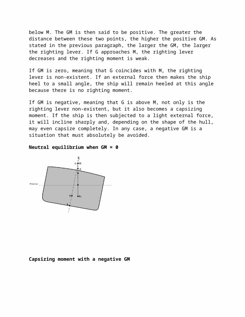
flooding cannot take place need not be considered as open. This interpretation is not intended to be applied to existing ships. The means of closing air pipes are to be weather tight and of an automatic type if the openings of the air pipes to which the devices are fitted would be submerged at an angle of less than 40 degrees (or any lesser angle which may be needed to suit stability requirements) when the ship is floating at its summer load line draught. Pressure/vacuum valves (P.V. valves) may be accepted on tankers. Wooden plugs and trailing canvas hoses may not be accepted in positions 1 and 2 as defined in Ch 1, Sec 2, [3.19].
Minimum righting leverThe righting lever GZ is to be at least 0,20 m at an angle of heel equal to or greater than 30°.
2.1.4 Angle of maximum righting leverThe maximum righting arm is to occur at an angle of heel preferably exceeding 30° but not less than 25°. When the righting lever curve has a shape with two maximums, the first is to be located at a heel angle not less than 25°.In cases of ships with a particular design and subject to the prior agreement of the flag Administration, the Society may accept an angle of heel qmax less than 25° but in no case less than 15°, provided that the area "A" below the righting lever curve is not less than the value obtained, in m.rad, from the following formula:A = 0,055+ 0,001 (30° - qmax) where qmax is the angle of heel in degrees at which the righting lever curve reaches its maximum.
Initial metacentric heightThe initial metacentric height GM0 is not to be less than 0,15 m.
Elements affecting stabilityA number of influences such as beam wind on ships with large windage area, icing of topsides, water trapped on deck, rolling characteristics, following seas, etc., which adversely affect stability, are to be taken into account.
Elements reducing stabilityProvisions are to be made for a safe margin of stability at all stages of the voyage, regard being given to additions of weight, such as those due to absorption of water and icing (details regarding ice accretion are given in [6]) and to losses of weight such as those due to consumption of fuel and stores.
GM0 and GZ curve correctionsThe corrections to the initial metacentric height and to the righting lever curve are to be addressed separately as indicated in [4.7.2] and [4.7.3].
In determining the correction to the initial metacentric height, the transverse moments of inertia of the tanks are to be calculated at 0 degrees angle of heel according to the categories indicated in [4.3.1].The righting lever curve may be corrected by any of the following methods:
Correction based on the actual moment of fluid transfer for each angle of heel calculated; corrections may be calculated according to the categories indicated in [4.3.1]Correction based on the moment of inertia, calculated at 0 degrees angle of heel, modified at each angle of heel calculated; corrections may be calculated according to the categories indicated. Correction based on the summation of Mfs values for all tanks taken into consideration, as specified in.Whichever method is selected for correcting the righting lever curve, only that method is to be presented in the ship's trim and stability booklet. However, where an alternative method is described for use in manually calculated loading conditions, an explanation of the differences which may be found in the results, as well as an example correction for each alternative, are to be included.
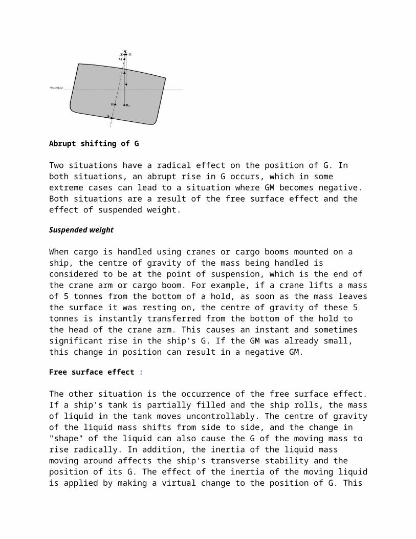
Requirements for Type B-60 shipsAny Type B ships of over 100 metres, having hatchways closed by weather tight covers as specified in [4.3], may be assigned freeboards less than those required for Type B, provided that, in relation to the amount of reduction granted, the requirements in [4.1.2] to [4.1.4] are considered satisfactory by the Society.In addition, the requirements stated in [3.4.2] are to be complied with.The measures provided for the protection of the crew are to be adequate.
The freeing arrangements are to comply with the provisions of Ch 9, Sec 9.
The covers in positions 1 and 2 comply with the provisions of [4.3] and have strength complying with Ch 9, Sec 7, special care being given to their sealing and securing arrangements.
Requirements for Type B-100 shipsIn addition to the requirements specified in [4.1], not taking into account the prescription stated in [3.4.2], the requirements in [4.2.2] to [4.2.4] are to be complied with.In addition, the provisions of [3.4.3] are to be complied with.
A-Class division:
Divisions formed by bulkheads and decks which comply following regulations:
Constructed of steel or other equivalent material.Suitably stiffened.Insulated with approved non-combustible materials such asThe average temperature of the unexposed side will not rise more than 140ºC above the original temperatureThe temperature at any one point, including any joint, rise more than 180ºC above the original temperature.Within the time period:
Class A-60 60 minClass A-30 30 minClass A-15 15 minClass A-0 0 min.
Constructed as to be capable of preventing the passage of smoke and flame to the end of the one hour standard fire test.A test is required as per FTP code.
Machinery casings:Machinery casings on Type A ships are to be protected by an enclosed poop or bridge of at least standard height, or by a deckhouse of equal height and equivalent strength, provided that machinery casings may be exposed if there are no openings giving direct access from the freeboard deck to the machinery space. A door complying with the requirements of [4.4] may, however, be permitted in the machinery casing, provided that it leads to a space or passageway which is as strongly constructed as the casing and is separated from the stairway to the engine room by a second weather tight door of steel or other equivalent material.
Gangway and access:
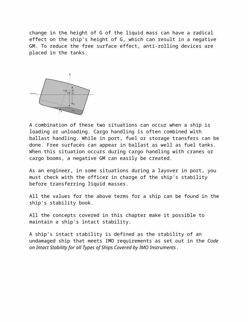
An efficiently constructed fore and aft permanent gangway of sufficient strength is to be fitted on Type A ships at the level of the superstructure deck between the poop and the midship bridge or deckhouse where fitted, or equivalent means of access is to be provided to carry out the purpose of the gangway, such as passages below deck. Elsewhere, and on Type A ships without a midship bridge, arrangements to the satisfaction of the Society are to be provided to safeguard the crew in reaching all parts used in the necessary work of the ship.Safe and satisfactory access from the gangway level is to be available between separate crew accommodation spaces and also between crew accommodation spaces and the machinery space.
Freeing arrangements:Type A ships with bulwarks are to be provided with open rails fitted for at least half the length of the exposed parts of the weather deck or other effective freeing arrangements. The upper edge of the sheer strake is to be kept as low as practicable.Where superstructures are connected by trunks, open rails are to be fitted for the whole length of the exposed parts of the freeboard deck.
Hatchways closed by weathertight covers of steel or other equivalent material fitted with gaskets and clamping devices
At positions 1 and 2 the height above the deck of hatchway coamings fitted with weathertight hatch covers of steel or other equivalent material fitted with gaskets and clamping devices is to be:600 millimetres if in position 1450 millimetres if in position 2.The height of these coamings may be reduced, or the coamings omitted entirely, upon proper justification. Where coamings are provided they are to be of substantial construction.
Where weathertight covers are of mild steel the strength is to be calculated with assumed loads not less than those specified in Ch 9, Sec 7.
The strength and stiffness of covers made of materials other than mild steel are to be equivalent to those of mild steel to the satisfaction of the Society.
The means for securing and maintaining weathertightness are to be to the satisfaction of the Society. The arrangements are to ensure that the tightness can be maintained in any sea conditions, and for this purpose tests for tightness are required at the initial survey, and may be required at periodical surveys and at annual inspections or at more frequent intervals.
4.4 Doors4.4.1 All access openings in bulkheads at ends of enclosed superstructures are to be fitted with doors of steel or other equivalent material, permanently and strongly attached to the bulkhead, and framed, stiffened and fitted so that the whole structure is of equivalent strength to the unpierced bulkhead and weathertight when closed. The means for securing these doors weathertight are to consist of gaskets and clamping devices or other equivalent means and are to be permanently attached to the bulkhead or to the doors themselves, and the doors are to be so arranged that they can be operated from both sides of the bulkhead.
4.4.2 Except as otherwise provided, the height of the sills of access openings in bulkheads at ends of enclosed superstructures is to be at least 380 millimetres above the deck.
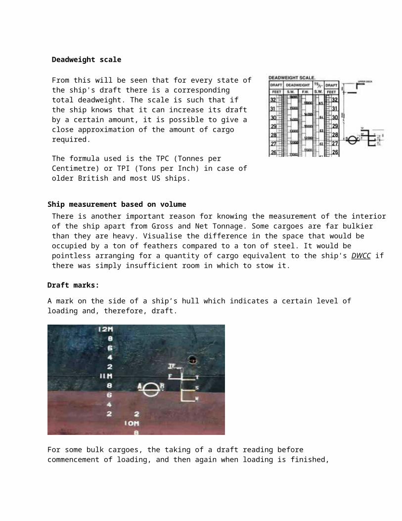
Downflood Height
Downflood height is the height above baseline of the lowest downflood point for a given condition of trim and heel. This may alternatively be given as the height above the waterline to the downflood point.
Downflood Angle
Downflood angle is the minimum angle (the lesser to port or to starboard) at which a downflood point meets the waterline for a given condition of load (displacement and draught).
• Obtaining Draught and trim
• Using the hydrostatic particulars provided on page MM, for zero trim, interpolate for the Displacement of the loading condition above and obtain values for Draught, LCB, LCF, MCT and KMT.
• Trim is calculated from the stated formula: If the LCB is forward of the LCG the trim is by the stern and if the LCB is aft of the LCG the trim is by the head (bow). It is to be noted that the trim so calculated is for the length used in the formulation of the hydrostatics – usually Length between perpendiculars (LBP) and will need to be corrected for the positions of the draught marks if significantly different.
• Stability compliance • The Free Surface Correction (FSC) is obtained by dividing column 8 of the Displacement row by the
Displacement (column 3 of the same row). • The KG liquid (KGL) is obtained by adding the FSC to the VCG in column 6 in the Displacement
row. (The effect of free surface is a virtual rise in the vertical centre of gravity) • The KG liquid (KGL) is compared with the KGmax obtained from page [NN]. If the KGL is less than
KGmax the loading condition complies with the stability criteria.
Hydrostatic Particulars
Tabular output showing Displacement, Draught, LCB, LCF, TPC, KMT and MCT across the range of operational draughts/displacements and trims.
Cross Curves of Stability:
Tabular output showing KN values across the range of operational draughts/displacements and trims.
NOTE:Water Density =1.025 T/m3
K is to underside of keel at amidships Draught is to underside of keel at amidships
Notes on use of KN CurvesKN curves for [displacements/draughts] of [X to Y tonnes/metres] are presented for angles of heel at intervals between [0 and Z] degrees.To obtain righting arm (GZ) curves at a given displacement, the following equation should be used:GZ = KN − KG sin θThis enables the value of GZ to be calculated at each of the heel angles presented, and subsequently

plotted as in the loading conditions presented herein.
Tank Usage and Free Surface Moments
Provided a tank is completely filled with liquid no movement of the liquid is possible and the effect on the ship’s stability is precisely the same as if the tank contained solid material. Immediately a quantity of liquid is withdrawn from the tank the situation changes completely and the stability of the ship is adversely affected by what is known as the ‘free surface effect’. This adverse effect on the stability is referred to as a ‘loss in GM’ or as a ‘virtual rise in VCG’ and is calculated as follows:
Virtual rise in VCG/ Loss of GM = Free Surface Mmt(Tonnes m)/
Vessel Displacement(Tonnes)
When preparing loading conditions, it is to be noted that free surface effects must be allowed for the maximum number of tanks which are slack or shortly to become slack in that given loading condition. [This will mean that, for departure conditions all main fuel tanks as well as fresh water tanks are considered to be slack.]
The number of slack tanks should be kept to a minimum. [Where port and starboard tanks are cross coupled, such connection should be closed at sea to minimise the reduction in stability.] Where ballast tanks are used they should be ‘pressed full’ or ‘empty’ as far as possible. Dirty water in the bilges must be kept to a minimum.
Pseudorange :
The distance between a satellite and a navigation satellite receiver (see GNSS positioning calculation) —for instance Global Positioning System (GPS) receivers.
To determine its position, a satellite navigation receiver will determine the ranges to (at least) four satellites as well as their positions at time of transmitting. Knowing the satellites' orbital parameters, these positions can be calculated for any point in time. The pseudoranges of each satellite are obtained by multiplying the speed of light by the time the signal has taken from the satellite to the receiver. As there are accuracy errors in the time measured, the term pseudo-ranges is used rather than ranges for such distances.
Pseudorange and time error estimation
Typically a quartz oscillator is used in the receiver to do the timing. The accuracy of quartz clocks in general is worse (i.e. more) than one part in a million; if the clock hasn't been corrected for a week, the distance will put you not on the Earth but outside the Moon's orbit. Even if the clock is corrected, a second later the clock is not usable anymore for positional calculation, because after a second the error will be hundreds of meters for a typical quartz clock. But in a GPS receiver the clock's time is used to measure the ranges to different satellites at almost the same time, meaning all the measured ranges have the same error. Ranges with the same error are called pseudoranges. By finding the pseudo-range of an additional fourth satellite for precisely position calculation, the time error can also be estimated. Therefore, by having the pseudoranges and the locations of four satellites, the actual receiver's position along the x, y, z axes and the time error can be computed accurately.

The reason we speak of pseudo-ranges rather than ranges, is precisely this "contamination" with unknown receiver clock offset. GPS positioning is sometimes referred to as trilateration, but would be more accurately referred to as pseudo-trilateration.
Following the laws of error propagation, neither the receiver position nor the clock offset are computed exactly, but rather estimated through a least squares adjustment procedure known from geodesy. To describe this imprecision, so-called GDOP quantities have been defined: geometric dilution of precision (x,y,z,t).
Pseudorange calculations therefore use the signals of four satellites to compute the receiver's location and the clock error. A clock with an accuracy of one in a million will introduce an error of one millionth of a second each second. This error multiplied by the speed of light gives an error of 300 meters. For a typical
satellite constellation this error will increase by about (less if satellites are close together, more if satellites are all near the horizon). If positional calculation was done using this clock and only using three satellites, just standing still the GPS would indicate that you are traveling at a speed in excess of 300 meters per second, (over 1000 km/hour or 600 miles an hour). With only signals from three satellites the GPS receiver would not be able to determine whether the 300m/s was due to clock error or actual movement of the GPS receiver.
If the satellites being used are scattered throughout the sky, then the value of geometric dilution of precision (GDOP) is low while if satellites are clustered near each other from the receiver's vantage point the GDOP values are higher. The lower the value of GDOP then the better the ratio of position error to range error computing will be, so GDOP plays an important role in calculating the receiver's position on the surface of the earth using pseudoranges. The larger the number of satellites, the better the value of GDOP will be
Collision avoidance:
AIS was developed to avoid collisions among large vessels at sea that are not within range of shore-based systems. Due to the limitations of VHF radio communications, and because not all vessels are equipped with AIS, the system is meant to be used primarily as a means of lookout and to determine the risk of collision rather than as an automatic collision avoidance system, in accordance with the International Regulations for Preventing Collisions at Sea.
When a ship is navigating at sea, information about the movement and identity of other ships in the vicinity is critical for navigators to make decisions to avoid collision with other ships and dangers (shoal or rocks). Visual observation (e.g., unaided, binoculars, and night vision), audio exchanges (e.g., whistle, horns, and VHF radio), and radar or Automatic Radar Plotting Aid are historically used for this purpose. These preventative mechanisms, however, sometimes fail due to time delays, radar limitations, miscalculations, and display malfunctions and can result in a collision.
While requirements of AIS are to display only very basic text information, the data obtained can be integrated with a graphical electronic chart or a radar display, providing consolidated navigational information on a single display.
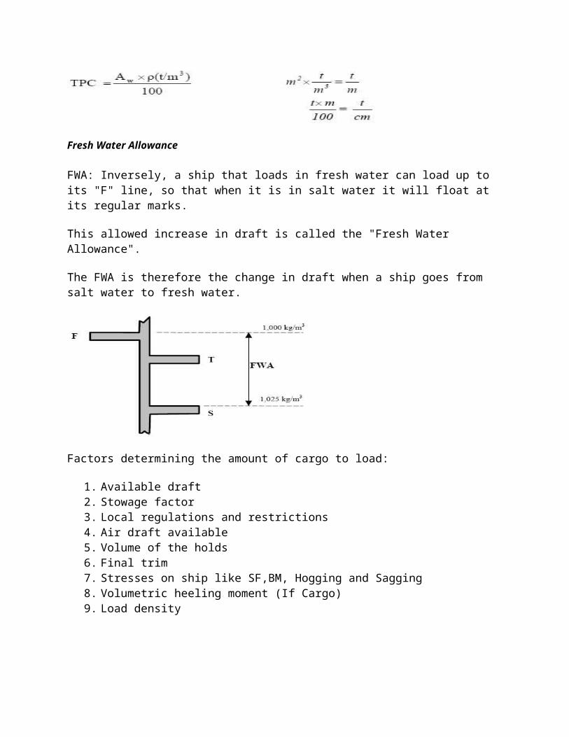
Vessel traffic services
In busy waters and harbors, a local vessel traffic service (VTS) may exist to manage ship traffic. Here, AIS provides additional traffic awareness and information about the configuration and movements of ships.
Maritime Security
AIS enables authorities to identify specific vessels and their activity within or near a nation's Exclusive Economic Zone. When AIS data is fused with existing radar systems, authorities are able to differentiate between vessels more easily. AIS improves maritime domain awareness and allows for heightened security and control.
Aids to navigation
AIS was developed with the ability to broadcast the positions and names of objects other than vessels, such as navigational aid and marker positions and dynamic data reflecting the marker's environment (e.g., currents and climatic conditions). These aids can be located on shore, such as in a lighthouse, or on water, platforms, or buoys. The U.S. Coast Guard has suggested that AIS might replace racon (radar beacons) currently used for electronic navigation aids.
The ability to broadcast navigational aid positions has also created the concepts of Synthetic AIS and Virtual AIS. In the first case, an AIS transmission describes the position of a physical marker but the signal itself originates from a transmitter located elsewhere. For example, an on-shore base station might broadcast the position of ten floating channel markers, each of which is too small to contain a transmitter itself. In the second case, it can mean AIS transmissions that indicate a marker which does not exist physically, or a concern which is not visible such as submerged rocks or a shipwreck. Although such virtual aids would only be visible to AIS-equipped ships, the low cost of maintaining them could lead to their usage when physical markers are unavailable.
Search and rescue
For coordinating on-scene resources of a marine search and rescue (SAR) operation, it is imperative to have data on the position and navigation status of other ships in the vicinity. In such cases, AIS can provide additional information and enhance awareness of available resources, even if the AIS range is limited to VHF radio range. The AIS standard also envisioned the possible use on SAR aircraft, and included a message (AIS Message 9) for aircraft to report their position. Recent regulations have mandated the installation of AIS systems on all Safety Of Life At Sea (SOLAS) vessels and vessels over 300 tons.
Accident investigation
AIS information received by VTS is important for accident investigation since it provides accurate data on time, identity, GPS-based position, compass heading, course over ground, speed (by log/SOG), and rates of turn, rather than the less accurate information provided by radar.
A more complete picture of the events could be obtained by Voyage Data Recorder (VDR) data if available and maintained on board for details of the movement of the ship, voice communication and

radar pictures during the accidents. However, VDR data are not maintained due to the limited twelve hours storage by IMO requirement.
Binary messages
AIS messages 6, 8, 25, and 26 provide "Application Specific Messages" (ASM), that allow "competent authorities" to define additional AIS message subtypes. There are both "addressed" (ABM) and "broadcast" (BBM) variants of the message. Addressed messages, while containing a destination MMSI, are not private and may be decoded by any receiver.
Computer AIS monitoring programs, by definition do not possess AIS transponders. Most AIS physical devices (like USB VHF radio dongles) do not contain AIS transponders. With these monitoring systems your position (or your vessel's position) will not be transmitted. However, these devices may be used as an inexpensive alternative to AIS devices for smaller vessels if no other viable alternative can be found. Ship enthusiasts also use such systems to track and find vessels to add to their photo collections.
Type testing and approval
AIS is a technology which has been developed under the auspices of the IMO by its technical committees. The technical committees have developed and published a series of AIS product specifications. Each specification defines a specific AIS product which has carefully created to work in a precise way with all the other defined AIS devices, thus ensuring AIS system interoperability worldwide. Maintenance of the specification integrity is deemed critical for the performance of the AIS system and the safety of vessels and authorities using the technology. As such most countries require that AIS products are independently tested and certified to comply with a specific published specification. Products that have not been tested and certified by a competent authority, may not conform to the required AIS published specification and therefore may not operate as expected in the field.
How AIS works
Search And Rescue Transponder (SART):
Specialist AIS device created as an emergency distress beacon which operates using pre-announce time-division multiple-access (PATDMA), or sometimes called a "modified SOTDMA". The device randomly selects a slot to transmit and will transmit a burst of eight messages per minute to maximize the probability of successful transmission. A SART is required to transmit up to a maximum of five miles and
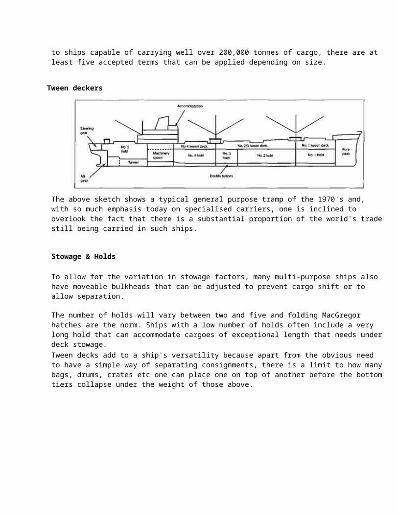
transmits a special message format recognized by other AIS devices. The device is designed for periodic use and only in emergencies due to its PATDMA-type operation which places stress on the slot map.
AIS receivers are not specified in the AIS standards, because they do not transmit. The main threat to the integrity of any AIS system are non-compliant AIS transmissions, hence careful specifications of all transmitting AIS devices. However, it is well to note that AIS transceivers all transmit on multiple channels as required by the AIS standards. As such single-channel, or multiplexed, receivers will not receive all AIS messages. Only dual-channel receivers will receive all AIS messages.
Message types
There are 27 different types of top level messages defined in ITU 1371-4 (out of a possibility of 64) that can be sent by AIS transceivers.[19][20]
Each AIS transponder consists of one VHF transmitter, two VHF TDMA receivers, one VHF Digital Selective Calling (DSC) receiver, and links to shipboard display and sensor systems via standard marine electronic communications (such as NMEA 0183, also known as IEC 61162). Timing is vital to the proper synchronization and slot mapping (transmission scheduling) for a Class A unit. Therefore, every unit is required to have an internal time base, synchronized to a global navigation satellite system (e.g. GPS) receiver. This internal receiver may also be used for position information. However, position is typically provided by an external receiver such as GPS, LORAN or an inertial navigation system and the internal receiver is only used as a backup for position information. Other information broadcast by the AIS, if available, is electronically obtained from shipboard equipment through standard marine data connections. Heading information, position (latitude and longitude), "speed over ground", and rate of turn are normally provided by all ships equipped with AIS. Other information, such as angle of heel, pitch and roll, destination, and ETA may also be provided.
An AIS transponder normally works in an autonomous and continuous mode, regardless of whether it is operating in the open seas or coastal or inland areas. AIS transponders use two different frequencies, VHF maritime channels 87B (161.975 MHz) and 88B (162.025 MHz), and use 9.6 kbit/s Gaussian minimum shift keying (GMSK) modulation over 25 or 12.5 kHz channels using the High-level Data Link Control (HDLC) packet protocol. Although only one radio channel is necessary, each station transmits and receives over two radio channels to avoid interference problems, and to allow channels to be shifted without communications loss from other ships. The system provides for automatic contention resolution between itself and other stations, and communications integrity is maintained even in overload situations.
In order to make the most efficient use of the bandwidth available, vessels that are anchored or moving slowly transmit less frequently than those that are moving faster or are maneuvering. The update rate ranges from 3 minutes for anchored or moored vessels, to 2 seconds for fast moving or maneuvering vessels, the latter being similar to that of conventional marine radar.
Each AIS station determines its own transmission schedule (slot), based upon data link traffic history and an awareness of probable future actions by other stations. A position report from one station fits into one of 2,250 time slots established every 60 seconds on each frequency. AIS stations continuously synchronize themselves to each other, to avoid overlap of slot transmissions. Slot selection by an AIS station is randomized within a defined interval and tagged with a random timeout of between 0 and 8 frames. When a station changes its slot assignment, it announces both the new location and the timeout for that location. In this way new stations, including those stations which suddenly come within radio range close to other vessels, will always be received by those vessels.

The required ship reporting capacity according to the IMO performance standard is a minimum of 2,000 time slots per minute, though the system provides 4,500 time slots per minute. The SOTDMA broadcast mode allows the system to be overloaded by 400 to 500% through sharing of slots, and still provides nearly 100% throughput for ships closer than 8 to 10 nmi to each other in a ship to ship mode. In the event of system overload, only targets further away will be subject to drop-out, in order to give preference to nearer targets, which are of greater concern to ship operators. In practice, the capacity of the system is nearly unlimited, allowing for a great number of ships to be accommodated at the same time.
The system coverage range is similar to other VHF applications. The range of any VHF radio is determined by multiple factors, the primary factors are: the height and quality of the transmitting antenna and the height and quality of the receiving antenna. Its propagation is better than that of radar, due to the longer wavelength, so it is possible to reach around bends and behind islands if the land masses are not too high. The look-ahead distance at sea is nominally 20 nmi (37 km). With the help of repeater stations, the coverage for both ship and VTS stations can be improved considerably.
The system is backward compatible with digital selective calling systems, allowing shore-based GMDSS systems to inexpensively establish AIS operating channels and identify and track AIS-equipped vessels, and is intended to fully replace existing DSC-based transponder systems.
Bore Tides:
The bore tide is a rush of seawater that returns to a shallow and narrowing inlet from a broad bay. Bore tides come in after extreme minus low tides created by the full or new moon.
Bore tides occur all over the world—there are around 60 of them—but only a few are large enough to make a name for themselves. One in China, for example, stretches almost 30 feet tall and travels more than 20 miles per hour. Alaska’s most famous bore tide occurs in Turnagain Arm, just outside Anchorage. It climbs up to 6 – 10 feet tall and can reach speeds of 10 to 15 miles per hour. It takes not just a low tide but also about a 27-foot tidal differential (between high and low tide) for a bore to form in Turnagain Arm. bore tide is a wave (or waves) of water formed by an incoming tide. Bore tides occur in narrow bays and rivers where they move against the current of the water.
Characteristics
Bore tides can be as large as 30 feet high and travel at speeds up to 25 mph; these statistics are for the largest known tidal bore, which occurs in the Qiantang River in China.
Bore tides occur when water has withdrawn to its lowest level, after extremely low tides have been formed by a full or new moon.
Bore tides exist in only 60 locations throughout the world. The Turnagain Arm and the Knik Arm in Alaska are the only two locations in the United States where bore tides occur. Other locations with bore tides include the Bay of Fundy in Nova Scotia, Canada, and the Amazon River in Brazil.
Semidiurnal means twice-daily. In relation to tides, this means that there are two tidal cycles per day. In other words, during a typical day the tides reach their highest point lowest point twice each day. Some locations only have once daily tide changes, or diurnal tides.
The basic cause of tides is gravity. As the the sun and moon pull at the Earth, the tides bulge in that direction. As we rotate, that location of pull is released, causing a tide.
Tidal changes are the net result of multiple influences that act over varying periods. These influences are called tidal constituents. The primary constituents are the Earth's rotation, the positions of the Moon and the Sun relative to Earth, the Moon's altitude (elevation) above the Earth's equator, and bathymetry.
Variations with periods of less than half a day are called harmonic constituents. Conversely, cycles of days, months, or years are referred to as long period constituents.
The tidal forces affect the entire earth, but the movement of the solid Earth is only centimeters. The atmosphere is much more fluid and compressible so its surface moves kilometers, in the sense of the contour level of a particular low pressure in the outer atmosphere.
Principal lunar semi-diurnal constituent:
In most locations, the largest constituent is the "principal lunar semi-diurnal", also known as the M2 (or M2) tidal constituent. Its period is about 12 hours and 25.2 minutes, exactly half a tidal lunar day, which is the average time separating one lunar zenith from the next, and thus is the time required for the Earth to rotate once relative to the Moon. Simple tide clocks track this constituent. The lunar day is longer than the Earth day because the Moon orbits in the same direction the Earth spins. This is analogous to the minute hand on a watch crossing the hour hand at 12:00 and then again at about 1:05½ (not at 1:00).
The Moon orbits the Earth in the same direction as the Earth rotates on its axis, so it takes slightly more than a day—about 24 hours and 50 minutes—for the Moon to return to the same location in the sky. During this time, it has passed overhead (culmination) once and underfoot once (at an hour angle of 00:00 and 12:00 respectively), so in many places the period of strongest tidal forcing is the above mentioned, about 12 hours and 25 minutes. The moment of highest tide is not necessarily when the Moon is nearest to zenith or nadir, but the period of the forcing still determines the time between high tides.
Because the gravitational field created by the Moon weakens with distance from the Moon, it exerts a slightly stronger than average force on the side of the Earth facing the Moon, and a slightly weaker force on the opposite side. The Moon thus tends to "stretch" the Earth slightly along the line connecting the two bodies. The solid Earth deforms a bit, but ocean water, being fluid, is free to move much more in response to the tidal force, particularly horizontally. As the Earth rotates, the magnitude and direction of the tidal force at any particular point on the Earth's surface change constantly; although the ocean never reaches equilibrium—there is never time for the fluid to "catch up" to the state it would eventually reach if the tidal force were constant—the changing tidal force nonetheless causes rhythmic changes in sea surface height.
Semi-diurnal range differences
When there are two high tides each day with different heights (and two low tides also of different heights), the pattern is called a mixed semi-diurnal tide.
Range variation: springs and neaps
The types of tides :
The semi-diurnal range (the difference in height between high and low waters over about half a day) varies in a two-week cycle. Approximately twice a month, around new moon and full moon when the Sun, Moon and Earth form a line (a condition known as syzygy) the tidal force due to the sun reinforces that due to the Moon. The tide's range is then at its maximum: this is called the spring tide, or just springs. It is not named after the season but, like that word, derives from the meaning "jump, burst forth, rise", as in a natural spring.
When the Moon is at first quarter or third quarter, the sun and Moon are separated by 90° when viewed from the Earth, and the solar tidal force partially cancels the Moon's. At these points in the lunar cycle, the tide's range is at its minimum: this is called the neap tide, or neaps (a word of uncertain origin).
Spring tides result in high waters that are higher than average, low waters that are lower than average, 'slack water' time that is shorter than average and stronger tidal currents than average. Neaps result in less extreme tidal conditions. There is about a seven-day interval between springs and neaps.
The Astronomical Tide-Producing Forces: General Considerations
At the surface of the earth, the earth's force of gravitational attraction acts in a direction inward toward its center of mass, and thus holds the ocean water confined to this surface. However, the gravitational forces of the moon and sun also act externally upon the earth's ocean waters. These external forces are exerted as tide-producing, or so-called "tractive" forces. Their effects are superimposed upon the earth's gravitational force and act to draw the ocean waters to positions on the earth's surface directly beneath these respective celestial bodies (i.e., towards the "sublunar" and "subsolar" points).
High tides are produced in the ocean waters by the "heaping" action resulting from the horizontal flow of water toward two regions of the earth representing positions of maximum attraction of combined lunar and solar gravitational forces. Low tides are created by a compensating maximum withdrawal of water from regions around the earth midway between these two humps. The alternation of high and low tides is caused by the daily (or diurnal) rotation of the earth with respect to these two tidal humps and two tidal depressions. The changing arrival time of any two successive high or low tides at any one location is the result of numerous factors later to be discussed.
Origin of the Tide-Raising Forces
To all outward appearances, the moon revolves around the earth, but in actuality, the moon and earth revolve together around their common center of mass, or gravity. The two astronomical bodies are held together by gravitational attraction, but are simultaneously kept apart by an equal and opposite centrifugal force produced by their individual revolutions around the center-of-mass of the earth-moon system. This balance of forces in orbital revolution applies to the center-of-mass of the individual bodies only. At the earth's surface, an imbalance between these two forces results in the fact that there exists, on the hemisphere of the earth turned toward the moon, a net (or differential) tide-producing force which acts in the direction of the moon's gravitational attraction, or toward the center of the moon. On the side of the earth directly opposite the moon, the net tide-producing force is in the direction of the greater centrifugal force, or away from the moon.
Similar differential forces exist as the result of the revolution of the center-of-mass of the earth around the center-of-mass of the earth-sun system.

The tide-raising forces at the earth's surface thus result from a combination of basic forces: (1) the force of gravitation exerted by the moon (and sun) upon the earth; and (2) centrifugal forces produced by the revolutions of the earth and moon (and earth and sun) around their common center-of-gravity (mass) or barycenter. The effects of those forces acting in the earth-moon system will here be discussed, with the recognition that a similar force complex exists in the earth-sun system.
With respect to the center of mass of the earth or the center of mass of the moon, the above two forces always remain in balance (i.e., equal and opposite). In consequence, the moon revolves in a closed orbit around the earth, without either escaping from, or falling into the earth - and the earth likewise does not collide with the moon. However, at local points on, above, or within the earth, these two forces are not in equilibrium, and oceanic, atmospheric, and earth tides are the result.
A sea-breeze:
(or onshore breeze) is a wind from the sea that develops over land near coasts. It is formed by increasing temperature differences between the land and water; these create a pressure minimum over the land due to its relative warmth, and forces higher pressure, cooler air from the sea to move inland. Generally, air temperature gets cooler relative to nearby locations as one moves closer to a large body of water.[1] The sea has a greater heat capacity than land and can therefore absorb more heat than the land, so the surface of the sea warms up more slowly than the land's surface.[2] As the temperature of the surface of the land rises, the land heats the air above it. The warm air is less dense and so it rises. This rising air over the land lowers the sea level pressure by about 0.2%. The cooler air above the sea, now with higher sea level pressure, flows towards the land into the lower pressure, creating a cooler breeze near the coast. The strength of the sea breeze is directly proportional to the temperature difference between the land and the sea. If the environmental wind field is greater than 8 knots and opposing the direction of a possible sea breeze, the sea breeze is not likely to develop.[3]
A land breeze:
Type of wind that blows from the land to the ocean. When there is a temperature difference between the land surface and the ocean, winds will move offshore. Although commonly associated with ocean shorelines, land breezes can also be experienced near any large body of water such as a lake.
Land breezes usually occur at night. During the day, the sun will heat land surfaces, but only to a depth of a few inches. At night, water will retain more of its heat than land surfaces. Water has a high heat capacity which is one reason hurricane season officially extends through the chilly November months. At night, the temperature of the land cools quickly without the insolation from the sun. Heat is rapidly re-radiated back to the surrounding air. The water along the shore will then be warmer than the coastal land creating a net movement of air from the land surfaces towards the ocean.
Why? The movement of the wind is a result of differences in air pressure over the land and the ocean. Warm air is less dense and rises. Cool air is more dense and sinks. As the temperature of the land surfaces cool, the warm air rises and creates a small area of high pressure near the land surface. Since winds blow from areas of high to low pressure, the net movement of wind is from the shore to the water.
1.Air temperatures decrease at night. 2.Rising air creates a thermal low at the ocean surface. 3.Cool air collects forming a high pressure zone above the surface of the ocean. 4.A low pressure zone forms above the land surface from the rapid loss of heat. 5.A high pressure zone forms as the cooler land cools the air immediately above the surface. 6.Winds aloft flow from the ocean to the land. 7.Winds at the surface flow from high to low pressure creating a land breeze.
A katabatic wind originates from radiational cooling of air atop a plateau, a mountain, glacier, or even a hill. Since the density of air is inversely proportional to temperature, the air will flow downwards, warming adiabatically as it descends. The temperature of the wind depends on the temperature in the source region and the amount of descent. In the case of the Santa Ana, for example, the wind can (but does not always) become hot by the time it reaches sea level. In the case of Antarctica, by contrast, the wind is still intensely cold.
The entire near-surface wind field over Antarctica is largely determined by the katabatic winds, particularly outside the summer season, except in coastal regions when storms may impose their own windfield.
Impacts
Katabatic winds are most commonly found blowing out from the large and elevated ice sheets of Antarctica and Greenland. The buildup of high density cold air over the ice sheets and the elevation of the

ice sheets brings into play enormous gravitational energy. Where these winds are concentrated into restricted areas in the coastal valleys, the winds blow well over hurricane force. In a few regions of continental Antarctica the snow is scoured away by the force of the katabatic winds, leading to "dry valleys".Since the katabatic winds are descending, they tend to have a low relative humidity which desiccates the region. Other regions may have a similar but lesser effect, leading to "blue ice" areas where the snow is removed and the surface ice evaporates, but is replenished by glacier flow from upstream.
An anabatic wind,
from the Greek anabatos, verbal of anabainein meaning moving upward, is a warm wind which blows up a steep slope or mountain side, driven by heating of the slope through insolation.[1][2] It is also known as an upslope flow. These winds typically occur during the daytime in calm sunny weather. A hill or mountain top will be radiatively warmed by the Sun which in turn heats the air just above it. Air at a similar altitude over an adjacent valley or plain does not get warmed so much because of the greater distance to the ground below it. The effect may be enhanced if the lower lying ground is shaded by the mountain and so receives less heat.
The air over the hill top is now warmer than the air at a similar altitude around it and will rise through convection. This creates a lower pressure region into which the air at the bottom of the slope flows, causing the wind. It is common for the air rising from the tops of large mountains to reach a height where it cools adiabatically to below its dew point and forms cumulus clouds. These can then produce rain or even thunderstorms.
Anabatic winds are particularly useful to soaring glider pilots who can use them to increase the aircraft's altitude (this necessitates flying through cloud which in some countries such as Australia is illegal). Anabatic winds can be detrimental to the maximum downhill speed of cyclists.
Conversely, katabatic winds are down-slope winds, frequently produced at night by the opposite effect, the air near to the ground losing heat to it faster than air at a similar altitude over adjacent low-lying land.
Pilot transfer arrangements – revised requirements enter into force on 01st July 2012
This newsletter outlines revised requirements as to pilot ladder arrangements which enter into force on 1
July 2012. A key issue is the interpretation of the installation date for such arrangements in order to
identify whether the revised requirements apply. DNV’s practice of applying the installation date for this
equipment, based on the latest instructions given by IMO, is stated below.
On DNV.com: Pilot transfer arrangements – revised requirements enter into force on 1 July 2012
In December 2010, IMO MSC 88 adopted MSC.308(88), which contains amendments to SOLAS
regulation V/23 on pilot transfer arrangements in order to update and improve safety aspects relating to
pilot transfers. Briefly, this means:
In force from 1 July 2012.
Applicable to new buildings.
Some requirements also apply to existing ships.

New buildings
The following bullet points summarise the implications of the revised requirements, which are to be
found in A.1045(27) from November 2011 and MSC.308(88) from December 2010, versus the old
SOLAS regulation V/23:
Mechanical pilot hoists shall not be used.
Slight changes to the construction of ladders (spacing of steps, retrieval line, marking).
Requirements as to arrangements where an accommodation ladder is used in conjunction with pilot ladders (e.g. angle of slope, securing against the ship side, opening direction of trapdoors, height above sea level).
Requirements to ensure the safe approach of the pilot boat (unobstructed ship’s side).
New requirements as to pilot ladder winch reels (positioning and securing).
Vessels in operation
The following summarises the implications for vessels in operation:
Mechanical pilot hoists shall not be used.
Other existing installations – no changes (assumed to be in accordance with the old requirements).
Replacements on existing ships shall in so far as is reasonable/practicable comply with the new requirements.
Shipside doors used for pilot transfer shall not open outwards. Applicable to ships constructed before 1 January 1994 (first survey on or after 1 July 2012).
Securing the accommodation ladder
One new requirement for new buildings is that the lower platform of the accommodation ladder must be
secured when this ladder is used as a pilot ladder. This may be done by permanent connection point(s) in
the hull, or alternatively other equipment such as suction or magnetic pads that provide a sufficient
holding force may be used (see below for examples).

Approval/Certification of the pilot ladder
New pilot ladders shall be approved or certified according to that stated below:
For ships flying an EU flag, the pilot ladder is required to be MED approved according to item A.1/4.49 of the MED Directive 96/98/EC as amended.
For ships not flying an EU flag, the pilot ladder shall be certified by the manufacturer as stipulated by MSC.308(88) V/23.2.3.
Installation date
An interpretation of the installation date is given by IMO in MSC/Circ.1375 (December 2010). This
interpretation was amended at MSC 90 (May 2012) and a revision MSC/Circ.1375/Rev.1 is to be
published by IMO in the near future with the following wording:
(note: only 1.2 is amended)
1.1, for ships for which the building contract is placed on or after 1 July 2012, or in the absence of the
contract, constructed on or after 1 July 2012, “installed on or after 1 July 2012” means any installation
on the ship; and
1.2, for ships other than those ships prescribed in .1 above, “installed on or after 1 July 2012” means a
contractual delivery date for the system, in its entirety or for individual components of the system, as
relevant, to the ship on or after 1 July 2012 or, in the absence of a contractual delivery date, the actual
delivery of the system, in its entirety or for individual components, to the ship on or after 1 July 2012.
This does not apply to equipment and arrangements covered by paragraph 1.4 of regulation V/23.
PARAMETIC ROLLING:Large roll angle quickly generated in head/stern or near head/stern sea conditions. Period is about half the natural roll period, occurs in phase with large pitch angle. There are two pitch cycles for each roll cycle and maximum roll always occurs when the ship is pitched down. Quite unexpectedly, the roll angle can increase from a few degrees to over 30 degrees in only a few cycles. On container ships, the violent motions could introduce extreme loads on containers and their securing systems, resulting failures and lost of containers overboard. in real-life, these ships have sustained one of the largest casualties in history with hundreds of containers damaged or lost overboard.

Today's Post-Panamax container ship designs feature wide beam and large bow flares in order to carry more containers on deck while still minimize the resistance with the stream lined underwater hull. As wave travels down along the hull, the stability (as indicated by GM) varies as the wave crests travel along the hull. When the bow is down due to moderate pitching couple with slight roll, the large flare suddenly immersed in the wave crest. The restoring buoyancy force plus the wave excitation force would "push" the ship to the other side. Similar action will happen on the other side as the bow pitch down in the next cycle. This coupled, synchronous motions could lead to large roll angles with sort period in few cycles even with moderately high waves.
Unpredictable
Due to the unexpected nature of the motion as compared with synchronous roll in following or beam seas on smaller and finer ships, parametric roll is quite dangerous. Unfortunately, it is a phenomenon can be duplicated in controlled model test environment and with time-domain computer simulations, but unpredictable in real seas when multiple seas and swells coming from different directions. From the research studies carried out so far, the following have been observed:
1. Parametric roll occurs when natural roll period is between 1.8 to 2.1 times the encounter period (normally associated with the pitching period)
2. Larger flare the more likely is the parametric roll angle and wider range of resonance. 3. It requires a group of waves above a threshold or critical height for parametric roll to be initiated
and sustained. The threshold depends on size and shape of the hull.
The frequency domain linear ship motion prediction tools cannot predict such occurrence and it is impractical to run the computer intensive time-domain simulations for all types of wave conditions and varying ship loading conditions.
What can you do about it?
First stay calm. When detecting the short roll period close to the pitching period, it is a warning of the parametric roll inception. Change heading to beam seas is the fastest way of getting rid of it. Then slowly come back to the original heading if necessary.
Nature has its way of taking care of things. For ship's loading condition with high GMs, i.e. shorter natural roll period say around 10 second, the waves that could cause the pitching period around 5 seconds are usually not very high and therefore unlikely to initiate parametric rolling in head/stern seas. However, the synchronous roll may occur in beam seas. So the way to reduce the roll is by heading into the sea.
For ship's loading conditions with low GMs, i.e. long natural roll periods, parametric roll in head/stern seas of moderately high seastate is likely. But synchronous roll in beam seas is unlikely. It is hoped that with future R&D, we will be able to correlate the parametric roll with predictive events such as large relative bow motions and bow submergence (indicating flare immersion), thereby alert the master in the route planning stage or change loading conditions (GMs) before departure.
GM and rolling period
Metacentre has a direct relationship with a ship's rolling period. A ship with a small GM will be "tender" - have a long roll period. An excessively low or negative GM increases the risk of a ship capsizing in rough weather. It also puts the vessel at risk of potential for large angles of heel if the cargo or ballast shifts, such as with the Cougar Ace. A ship with low GM is less safe if damaged and partially flooded because the lower metacentric height leaves less safety margin. For this reason, maritime regulatory agencies such as the International Maritime Organization specify minimum safety margins for sea-going vessels. A larger metacentric height on the other hand can cause a vessel to be too "stiff"; excessive stability is uncomfortable for passengers and crew. This is because the stiff vessel quickly responds to the sea as it attempts to assume the slope of the wave. An overly stiff vessel rolls with a short period and high amplitude which results in high angular acceleration. This increases the risk of damage to the ship and to cargo and may cause excessive roll in special circumstances where eigenperiod of wave coincide with eigenperiod of ship roll. Roll damping by bilge keels of sufficient size will reduce the hazard. Criteria for this dynamic stability effect remains to be developed. In contrast a "tender" ship lags behind the motion of the waves and tends to roll at lesser amplitudes. A passenger ship will typically have a long rolling period for comfort, perhaps 12 seconds while a tanker or freighter might have a rolling period of 6 to 8 seconds.
The period of roll can be estimated from the following equation, where g is the gravitational constant, k is the radius of gyration about the longitudinal axis through the centre of gravity and is the stability index.
Damaged stability
If a ship floods, the loss of stability is caused by the increase in B, the centre of buoyancy, and the loss of waterplane area - thus a loss of the waterplane moment of inertia - which decreases the metacentric height. This additional mass will also reduce freeboard (distance from water to the deck) and the ship's angle of down flooding (minimum angle of heel at which water will be able to flow into the hull). The range of positive stability will be reduced to the angle of down flooding resulting in a reduced righting lever. When the vessel is inclined, the fluid in the flooded volume will move to the lower side, shifting its centre of gravity toward the list, further extending the heeling force. This is known as the free surface effect.
A material safety data sheet (MSDS):
safety data sheet (SDS), or product safety data sheet (PSDS) is an important component of product stewardship and Occupational safety and health. It is intended to provide workers and emergency personnel with procedures for handling or working with that substance in a safe manner, and includes information such as physical data (melting point, boiling point, flash point, etc.), toxicity, health effects, first aid, reactivity, storage, disposal, protective equipment, and spill-handling procedures. MSDS formats can vary from source to source within a country depending on national requirements.
SDSs are a widely used system for cataloging information on chemicals, chemical compounds, and chemical mixtures. SDS information may include instructions for the safe use and potential hazards associated with a particular material or product. These data sheets can be found anywhere where chemicals are being used. There is also a duty to properly label substances on the basis of physico-

chemical, health and/or environmental risk. Labels can include hazard symbols such as the European Union standard black diagonal cross on an orange background, used to denote a harmful substance.
An SDS for a substance is not primarily intended for use by the general consumer, focusing instead on the hazards of working with the material in an occupational setting. In some jurisdictions, the SDS is required to state the chemical's risks, safety, and effect on the environment.
It is important to use an SDS specific to both country and supplier, as the same product (e.g. paints sold under identical brand names by the same company) can have different formulations in different countries. The formulation and hazard of a product using a generic name (e.g. sugar soap) may vary between manufacturers in the same country.
Angle of loll:
Angle of loll is a term used to describe the state of a ship which is unstable when upright (ie: has a negative metacentric height, GM) and therefore takes on an angle of heel to either port or starboard.When a vessel has negative GM i.e., is in unstable equilibrium, any external force, if applied the vessel, will cause it to start heeling. As the heels, its underwater volume increases, which increases the vessel's BM (distance from the center of buoyancy to the metacenter). Since there is no change in KB (distance from the keel to the center of buoyancy) of the vessel, the KM (distance from keel to the metacenter) of the vessel increases.
At some angle of heel (say 10°), KM will increase sufficiently equal to KG (distance from the keel to the center of gravity), thus making GM of vessel equal to zero. When this occurs, the vessel goes to neutral equalibrium, and the angle of heel at which it happens is called angle of loll, In other words, when an unstable vessel heels over towards a progressively increasing angle of heel, at a certain angle of heel, the center of buoyancy (B) may fall vertically below the center of gravity (G). Note that Angle of List should not be confused with angle of loll. Angle of List is caused by unequal loading on either side of center line of vessel.
Although vessel at angle of loll does display features of stable equilibrium, it is an extremely dangerous situation, timely remedial action is required to prevent the vessel from capsizing.
It is often caused by the influence of a large free surface or the loss of stability due to damaged compartments. It is different from list in that the vessel is not induced to heel to one side or the other by the distribution of weight, it is merely incapable of maintaining a zero heel attitude.

Angle of Repose:
(a) This is the maximum angle you can have the grain at. Check out the stability book to make sure you can safely take this amount of grain onboard. Make sure the ship is fumigated before the grain is taken aboard (it can be oxygen deficient or have flammable gases in it)
When a ship is fumigated, the detailed recommendations contained in the Recommendations on the Safe Use of Pesticides in Ships" should be followed. Spaces adjacent to fumigated spaces should be treated as if fumigated.
Failure to observe simple procedures can lead to people being unexpectedly overcome when entering enclosed spaces. Observance of the principals outlined above will form a reliable basis for assessing risks in such spaces and for taking necessary precautionsCheck out the grain loading plansCheck out the stowage details for the grainFind out the type of grain carried and see what (if any) gases it gives offFind the total weight of the grainFind out what draft and freeboard you have before loading and after loadingMake sure that the grain cannot shift by taking precautions using boards transversely and athwart ships to minimize F.S.E. (Free Surface Effect)Watch for overheating (sweating though Cargo sweat or Ships sweat) both are dangerous and can ignite and explode by itself
MLC 2010 and the seafarer onboard a ship - some new bits . . .Many shipowners and seafarers do not realise it as yet, but the Maritime Labour Convention 2010 (MLC 2010) which is going to come into force next year (2011), will be implemented by Port State Control. So it does not matter if your Flag State has ratified or signed on to the convention or not - if the Port State has signed on, then compliance by owners, operators, Master and seafarers will be essential.
So what are the significant changes for seafarers?One aspect would be the contract between seafarer and owner. Some significant new points would include:-# The seafarer has been given enough time to read and review and also take advice on the contract or agreement before signing. What is "enough time"? That is left to the seafarer. If he feels he has not been given enough time, then he asks for more.# The full name and address of the shipowner will have to be entered into the contract or agreement. In case the ownership is multiple layered, then all the names and addresses will be required to be entered.# Full details of the health and social security benefits provided to the seafarer shall have to be entered. In this context, the new rules pertaining to NRIs and "foreign workers/Indians working abroad" under the EPFO may also be seen.# Where the seafarer is liable for any reason to pay for his repatriation and other expenses, then a maximum amount needs to be set out in the contract/agreement itself. This can not be open ended as it is now.# A :Shipowner's Complaint Procedure" will have to be defined and made available to the seafarer. The exact mechanics of this are yet unknown, but it is expected that this will have provision for referral back to flag and port state.

# Disciplinary rules and procedures will have to be set down, in detail, in keeping with flag and port state requirements. This appears to be a tough one. Each Port State will have different rules for such actions.# On rest periods, much was expected, but little has changed. Maximum interval between 2 rest periods will be 14 hours. Extra work impacting rest hours for any reason - emergency, drills, musters, safety, peril - must be compensated.# Termination of contract by seafarer for urgent or compassionate reasons shall be without cost to the seafarer. Notice period for termination of contract shall be not less than 7 days on both sides, and both seafarer as well as shipowner shall have equal number of days for this.# Dental treatment will now be included in medical care, when visiting doctors ashore.
Ofcourse, the above is still evolving, and there may be variations as and when the MLC 2010 comes into force in your Flag State. But expect the Port State Control to implement their version of MLC 2010 with vigour, and soon.
STCW applies to:
- Watch-going personnel, deck and engine- Master & Chief Engineers- Personnel designated to safety and security related matters - Able seafarer deck & engineMLC applies to: - All seafarers
Changes to Competence Tables, like:- Deck Officers’ ECDIS Competence- Engineer Officers’ pollution prevention equipment competence- New guidance for crew on offshore support vessels and ships in polar waters
Leadership and Teamwork- For all officers substantial new requirements on leadership, teamwork and managerial skills - Assertiveness training will be required for all seafarers
Training Record Books- All deck and engine rating trainees will have to demonstrate competence through onboardtraining record books, supervised by responsible officers
STCW and MLC (2012-02-07) New STCW requirements
Mandatory Security Training- New security familiarization and training requirements for all grades of shipboard personnel - Seafarers may already comply through seagoing service or previous trainingTanker Competence Tables- New and comprehensive tables for training in oil, chemical and gas tanker operation at bothbasic and advanced levels
Medical Standards- Additional medical fitness standards and requirements for health certification
New Seafarer Grades and Certification- New training and certification requirements for:- Able Seafarer Deck

- Able Seafarer Engine- Electro-Technical Officer- Electro-Technical Rating
Refresher Training- All seafarers are required to provide evidence of competence in basic safety training- Much of the refresher training can be conducted onboard, but some will require training ashore- Seafarers holding certificates of proficiency for survival craft, rescue boats and fast rescue boats or advanced firefighting must show maintenance of these competencies every 5 years
Minimum Hours of Rest- Goal to harmonize with MLC- New limits:- Minimum 77 hours in any 7 day period- Minimum 10 hours in an any 24 hour period (except during emergency)- Mandatory maintenance of records of hours of rest for each individual seafarer- The rest hours are applicable to all seafarers on board, including Masters- From January 1st 2012 seafarers will have to review and sign their record of hours of rest- It is expected that Port State Control will pay increasing attention to Hours of Rest!
STCW Transition periodSeafarers holding certificates issued prior to January 1st 2012 have to meet new requirements in order for certificates to be revalidated beyond January 1st 2017From January 1st 2014 all seafarers will have to be trained and certified in security mattersFrom 2017 all medical certificates must be issued in accordance with the 2010 amendmentsRest hours- Ten hours in any 24 hours period - 77 hours in any 7 days period- 2 rest periods
Training and competence- Certificates issued in accordance with STCW shall be accepted under MLC- All seafarers shall be trained or certified as competent or otherwise qualified to perform their duties under MLC (those not covered by STCW)- All seafarers shall have successfully completed training for personal safety
Medical certificates - Certificates issued in accordance with STCW shall be accepted under MLC- Joint Working Group (JWG) between IMO and ILO to align medical certification of seafarers as well as harmonizing requirements for ships’ medicine chest On-going.
TRANSIT BEARING:
The bearing of a great circle projected through two known points and the observer. It is a line drawn on a chart through two features observed to be in line (i.e., in transit) and which passes through the aircraft’s position at the time of the sighting. This line, a true bearing, is also a position line.
Double Bottom:Double Bottom is a construction method used in the construction of a ship. The double bottom space is formed by fitting of additional plating above the bottom plating, extending from side to side and over most of the length of the vessel. The inner bottom plating is called the Tank Top is constructed to provide a watertight space below it. This watertight space is called a double bottom tank. Most dry cargo ships and bulk carriers are fitted with double bottoms. Many tankers are also being constructed with these structural arrangements.
Typically, double bottom depths vary from 1-1.5m. the following are some of the advantages of double bottomed ships:
1. Provide double protection to the hull in case of grounding or bottom damage. Helps to prevent pollution in case of tankers.2. Provides great longitudinal strength to the bottom of the ship where there is most required. As the mass of the cargo acts on the bottom, this area needs to be the strongest especially when carrying high-density cargoes.3. Can be used for carriage of fuel oil, ballast or fresh water.4. Because of their location, Double Bottoms help to maintain safe levels of stability (GM) during ballast passages while providing the required draughts and trim.5. Since most of the Double Bottoms are longitudinally divided, from surface effects due to slack tanks are reduced to negligible levels.
Construction within the Double Bottom: the compartment may be transversely or longitudinally framed.
Transversely framed double bottom:
1. A water tight centre girder divides the compartment into two separate tanks, port and star board. Side girders will also be fitted on either side of the center girder. These are not usually watertight and are provided with lightening holes for air, liquid flow and access. The girders extend the full depth of the double bottom tank.2. Transversely, three types of floors are fitted in Double Bottom, namely watertight floor- these are solid plates extending the full depth of the Double Bottom and the entire breadth of the tank. They are fitted underneath the watertight bulkhead and provided water tightness between tanks in the longitudinal direction. These are the strongest floor.
Plate FloorThese are plates very similar to the water tight floors, but having lightening holes cut in them, so that they are not water tight. Air holes, drain holes are also provided.
Bracket FloorFitted between plate floors to provide support for the tank top. The main part of the plate is omitted and

only a bar is fitted. On each side of the center girder and at the side, flanged brackets are found.
Longitudinally framed double bottom :
1. Bottom longitudinals are fitted both on the bottom plating as well as under the tank top. Centre and side girders as in the transversely framed Double Bottom above.2. Floor arrangement is similar to the transversely framed Double Bottom, except that in the case of the bracket, the bar is omitted.
Parts of Magnetic compass:Pellorus, compass card, Binacle, magnets, heeling error bucket, sphere, needle, Flinder bars Sprit Liquid.
SPEED LOGS: Speed and distance run indicated on a large illuminated LCD display. Compact display unit and transducer. High accuracy by utilizing the Doppler principle, paired beam eliminating effect of pitching, and velocity correction for change of water temperature. Easy speed correction at mile post run. Speed output to ARPA, radar, ECDIS, AIS, VDR, GMDSS equipment, etc.
Complies with IMO standards MSC.96(72), A.824(19), A.694(17), IEC 61023 and other related standards. Fully meets SOLAS carriage requirement for ships over 300GT. Fits to the hull either directly or with a gate valve.An Electromagnetic Log, sometimes called an "EM Log", measures the speed of a vessel through water. It operates on the principle that:
when a conductor (such as water) passes through an electromagnetic field, a voltage is created and the amount of voltage created increases as the speed of the conductor increases.
The process is the EM Log creates an electromagnetic field. a voltage is induced in the water; the magnitude of the voltage varies depending upon the speed of the water flow past the sensor. the EM Log measures the voltage created and translates this into the vessel's speed through water.
Advantages: No moving parts
Disadvantages: Salinity and temperature of water affects calibration.
Measurements affected by boundary layer, (water speed slowed down close to the hull by friction).
Galvanic series
Metals can be arranged in a galvanic series representing the potential they develop in a given electrolyte against a standard reference electrode. The relative position of two metals on such a series gives a good indication of which metal is more likely to corrode more quickly. However, other factors such as water aeration and flow rate can influence the process markedly.

Galvanic corrosion is of major interest to the marine industry. Galvanic series tables for seawater are commonplace due to the extensive use of metal in shipbuilding. It is possible that corrosion of silver brazing in a salt water pipe caused a failure that led to the USS Thresher sinking with all men lost.
The common technique of cleaning silver by immersion of the silver and a piece of alluminium in an electrolytic bath (usually sodium bicarbonate) is an example of galvanic corrosion. (Care should be exercised for reasons such as this will strip silver oxide from the silver which may be there for decoration. Use on plated silver is inadvisable as this may introduce unwanted galvanic corrosion with the base metal.)
Preventing galvanic corrosion:
There are several ways of reducing and preventing this form of corrosion. One way is to electrically insulate the two metals from each other. Unless they are in electrical contact, there can be no galvanic couple set up. This can be done using plastic or another insulator to separate steel water pipes from copper-based fittings or by using a coat of grease to separate aluminium and steel parts. Use of absorbent washers that may retain fluid is often counter-productive. Piping can be isolated with a spool of pipe made of plastic materials or made of metal material internally coated or lined. It is important that the spool has a minimum length of approx 500 mm to be effective.
Another way is to keep the metals dry or shielded from ionic compounds (salts, acids, bases), for example by painting or encasing the protected metal in plastic or epoxy, and allowing them to dry.
Coating the two materials or if it is not possible to coat both, the coating shall be applied to the more noble, the material with higher potential. This is necessary because if the coating is applied only on the more active material, in case of damage of the coating there will be a large cathode area and a very small anode area, and for the area effect the corrosion rate will be very high.
It is also possible to choose metals that have similar potentials. The more closely matched the individual potentials, the lesser the potential difference and hence the lesser the galvanic current. Using the same metal for all construction is the most precise way of matching potentials.
Finally, an electrical power supply may be connected to oppose the corrosive galvanic current. Cathodic protection on ships is often implemented by galvanic anodes attached to the hull, rather than using ICCP. Since ships are regularly removed from the water for inspections and maintenance, it is a simple task to replace the galvanic anodes.
Galvanic anodes are generally shaped to reduced drag in the water and fitted flush to the hull to also try to minimize drag. Smaller vessels, with non-metallic hulls, such as yachts, will also use galvanic anodes to protect areas such as the rudder, but depend on an electrical connection between the anode and the item to be protected.
ICCP on ships:
DC power supply is provided within the ship and the anodes mounted on the outside of the hull. The anode cables are introduced into the ship via a compression seal fitting and routed to the DC power source. The negative cable from the power supply is simply attached to the hull to complete the circuit. Ship ICCP anodes are flush-mounted, minimizing the effects of drag on the ship, and located a minimum
5 ft below the light load line in an area to avoid mechanical damage. The current density required for protection is a function of velocity and considered when selecting the current capacity and location of anode placement on the hull.
Some ships may require specialist treatment, for example aluminium hulls with steel fixtures will create an electrochemical cell where the aluminum hull can act as a galvanic anode and corrosion is enhanced. In cases like this, aluminium or zinc galvanic anodes can be used to offset the potential difference between the aluminium hull and the steel fixture. If the steel fixtures are large, several galvanic anodes may be required, or even a small ICCP system.
For example, consider a system is composed of 316 SS (a 300 series stainless steel; it is a very noble alloy meaning it is quite resistant to corrosion and has a high potential) and a mild steel (a very active metal with lower potential). The mild steel will corrode in the presence of an electrolyte such as salt water. If a sacrificial anode is used (such as a zinc alloy, aluminium alloy, or magnesium), these anodes will corrode, protecting the other metals. This is a common practice in the marine industry to protect ship equipment. Boats and vessels that are in salt water use either zinc alloy or aluminum alloy. If boats are only in fresh water, a magnesium alloy is used. Magnesium has one of the highest galvanic potentials of any metal. If it is used in a salt water application on a steel or aluminum hull boat, hydrogen bubbles will form under the paint, causing blistering and peeling.
What is Static Electricity?
Everything we see is made up of tiny little parts called atoms. The atoms are made of even smaller parts. These are called protons, electrons and neutrons. They are very different from each other in many ways. One way they are different is their "charge." Protons have a positive (+) charge. Electrons have a negative (-) charge. Neutrons have no charge.
Usually, atoms have the same number of electrons and protons. Then the atom has no charge, it is "neutral." But if you rub things together, electrons can move from one atom to another. Some atoms get extra electrons. They have a negative charge. Other atoms lose electrons. They have a positive charge. When charges are separated like this, it is called static electricity.
If two things have different charges, they attract, or pull towards each other. If two things have the same charge, they repel, or push away from each other.
So, why does your hair stand up after you take your hat off? When you pull your hat off, it rubs against your hair. Electrons move from your hair to the hat. Now each of the hairs has the same positive charge. Things with the same charge repel each other. So the hairs try to move away from each other. The farthest they can get is to stand up and away from all the other hairs.

If you walk across a carpet, electrons move from the rug to you. Now you have extra electrons. Touch a door knob and ZAP! The electrons move from you to the knob. You get a shock.
ECA:
It was a long time coming. What some are hailing as landmark international regulations to reduce air pollution from ships in North American waters took effect this month.
It’s called an Emission Control Area, or ECA, and it is now in place a mere two years after the International Maritime Organization approved an application from the U.S. and Canada to create this “lower pollution zone.”
The ECA’s provisions are designed to prevent tons of harmful pollutants from entering the atmosphere from ships’ smokestacks. Many of these air pollutants, such as nitrogen oxides, sulfur oxides and particulate matter, significantly impact the health of coastal communities and can travel hundreds of miles inland as well.
The EPA, which will oversee the program in the U.S., estimates that implementing the ECA will prevent between 12,000 and 31,000 premature deaths each year across the U.S. and save billions of dollars in health care costs by 2030.
Under the ECA, ships coming within 200 nautical miles of the U.S. and Canada are required to burn cleaner fuels. And those standards will become even more stringent by 2015 – bringing Canada and the U.S. in line with similar European restrictions.
Most large vessels, including cargo, container and cruise ships, burn bunker fuel, one of the dirtiest fuels on the planet. It is thousands of times dirtier than diesel truck fuel, according to the EPA. In addition to its air-polluting qualities, when bunker fuel is spilled it is almost impossible to clean up and is extremely destructive to oceans, coastal waters and the marine life living in those waters.
Well, perhaps not entirely broad or bi-partisan. The cruise industry is working hard to water down the ECA, lobbying Congress and the Obama administration to put in place measures that would allow it to bypass the ECA’s rules. The cruise industry claims that it will have to avoid North American waters if the ECA’s standards go into effect, citing increasing costs due to switching to less polluting fuel and replacing ship equipment to accommodate that fuel. The industry’s recent efforts include attempts to amend the ECA to exempt cruise ships from the cleaner fuel requirements in less populated areas like Alaska and Hawaii.
The ECA is also part of a growing trend to reduce shipping emissions. More than 50 ports across are already reducing their carbon emissions as part of the World Ports Climate Initiative.
Adoption, entry into force & date of taking effect of Special Areas
Special Areas Adopted Date of Entry into Force In Effect From
Annex I: Oil
Mediterranean Sea 2 Nov 1973 2 Oct 1983 2 Oct 1983
Baltic Sea 2 Nov 1973 2 Oct 1983 2 Oct 1983Black Sea 2 Nov 1973 2 Oct 1983 2 Oct 1983Red Sea 2 Nov 1973 2 Oct 1983 *"Gulfs" area 2 Nov 1973 2 Oct 1983 1 Aug 2008Gulf of Aden 1 Dec 1987 1 Apr 1989 *Antarctic area 16 Nov 1990 17 Mar 1992 17 Mar 1992North West European Waters 25 Sept 1997 1 Feb 1999 1 Aug 1999Oman area of the Arabian Sea 15 Oct 2004 1 Jan 2007 *Southern South African waters 13 Oct 2006 1 Mar 2008 1 Aug 2008
Annex II: Noxious Liquid SubstancesAntarctic area 30 Oct 1992 1 Jul 1994 1 Jul 1994
Annex IV: Sewage Baltic Sea 15 Jul 2011 1 Jan 2013 **
Annex V: GarbageMediterranean Sea 2 Nov 1973 31 Dec 1988 1 May 2009Baltic Sea 2 Nov 1973 31 Dec 1988 1 Oct 1989Black Sea 2 Nov 1973 31 Dec 1988 *Red Sea 2 Nov 1973 31 Dec 1988 * "Gulfs" area 2 Nov 1973 31 Dec 1988 1 Aug 2008North Sea 17 Oct 1989 18 Feb 1991 18 Feb 1991Antarctic area (south of latitude 60 degrees south) 16 Nov 1990 17 Mar 1992 17 Mar 1992Wider Caribbean region including the Gulf of Mexico and the Caribbean Sea 4 Jul 1991 4 Apr 1993 1 May 2011
Annex VI: Prevention of air pollution by ships (Emission Control Areas)Baltic Sea (SOx) 26 Sept 1997 19 May 2005 19 May 2006North Sea (SOx) 22 Jul 2005 22 Nov 2006 22 Nov 2007 NorthAmerican (SOx, and NOx and PM) 26 Mar 2010 1 Aug 2011 1 Aug 2012 UnitedStates CaribbeanSeaECA (SOx, NOx and PM) 26 Jul 2011 1 Jan 2013 1 Jan 2014
Port State Control:
(PSC) is the inspection of foreign ships in other national ports by PSC officers (inspectors) for the purpose of verifying that the competency of the Master and Officers on board, and the condition of the ship and its equipment comply with the requirements of international conventions (e.g. SOLAS, MARPOL, STCW, etc.) and that the vessel is manned and operated in compliance with applicable international law.
Under Port State Control (PSC), inspection of ships in port would be taken by Port State Control Officer (PSCO). Detention of the ship is the last course of action that a PSCO would take upon finding deficiencies aboard the vessel.

Courses of action a PSCO may impose on a ship with deficiencies (in order of ascending gravity):
1. Deficiencies can be rectified within 14 days for minor infractions2. Under specific conditions, deficiencies can be rectified when the ship arrives at the next port3. Deficiencies must be rectified before the ship can depart the port;4. Detention of the ship
Criteria for detaining a ship by PSCO
The main criteria for detention is that the ship is deemed unsafe to proceed to sea and that the deficiencies on a ship are considered serious by the inspector. These deficiencies must be rectified before the ship may sail again. In the annual report of Paris MOU, it stated that the major deficiencies are:1. Certification of crew2. Safety3. Maritime Security4. Marine Pollution and Environment5. Working and Living Condition6. Operational7. ManagementThese deficiencies are the most common concern of a PSCO. When these deficiencies are clearly hazardous to safety, health, or the environment, the PSCO would require the hazard to be rectified before the ship can sail or detain the vessel or even issue a formal prohibition of the ship to operate. As these deficiencies are self-induced by the ship operator or the ship owner, detention under PSC for the reasons listed above is not able to reach a frustration to discharge the contract on the vessel.
Short period of detention cannot discharge the contract through frustration
The contract cannot be discharged by frustration if the time under detention is not long enough to provoked the frustration doctrine.
PSC requirement upon detaining a ship
The PSC require a ship being detained to remedy the deficiencies, which caused the detention. If the deficiencies cannot be remedied in the port of inspection, the port state would allow the ship to proceed to another port under special condition. The ship become free of detention only when all the fee induced by the inspection and detention is paid by the ship-owner.
No party wants a long detention
Rationally, both the port state and the ship-owner do not want the ship to be detained for a long time. For the port state, the hazard of the ship might affect the condition of the port, and the ship-owner understand the vessel can only make money when it is sailing. Neither party would have the intention to keep the vessel being detained for an extremely long period of time. Therefore, the time of detention is normally not long enough to provoke the detention doctrine to discharge a contract.
International Maritime Dangerous Goods (IMDG) Code
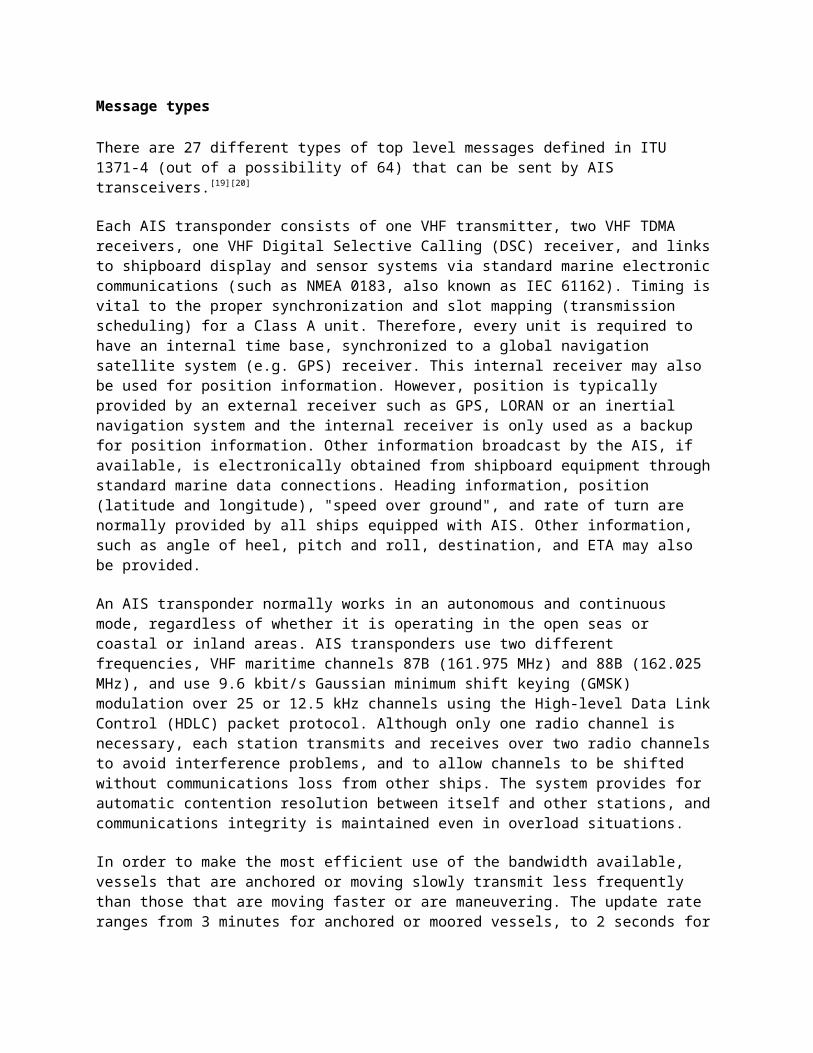
The International Maritime Dangerous Goods (IMDG) Code was developed as a uniform international code for the transport of dangerous goods by sea covering such matters as packing, container traffic and stowage, with particular reference to the
Development of the IMDG Code
The development of the IMDG Code dates back to the 1960 Safety of Life at Sea Conference, which recommended that Governments should adopt a uniform international code for the transport of dangerous goods by sea to supplement the regulations contained in the 1960 International Convention for the Safety of Life at Sea (SOLAS).
A resolution adopted by the 1960 Conference said the proposed code should cover such matters as packing, container traffic and stowage, with particular reference to the segregation of incompatible substances.
A working group of IMO's Maritime Safety Committee began preparing the Code in 1961, in close co-operation with the United Nations Committee of Experts on the Transport of Dangerous Goods, which in a 1956 report had established minimum requirements for the transport of dangerous goods by all modes of transport.
Since its adoption by the fourth IMO Assembly in 1965, the IMDG Code has undergone many changes, both in appearance and content to keep pace with the ever-changing needs of industry. Amendments which do not affect the principles upon which the Code is based may be adopted by the MSC, allowing IMO to respond to transport developments in reasonable time.
Amendments to the IMDG Code originate from two sources; proposals submitted directly to IMO by Member States and amendments required to take account of changes to the United Nations Recommendations on the Transport of Dangerous Goods which sets the basic requirements for all the transport modes.
Amendments to the provisions of the United Nations Recommendations are made on a two-yearly cycle and approximately two years after their adoption, they are adopted by the authorities responsible for regulating the various transport modes. In that way a basic set of requirements applicable to all modes of transport is established and implemented, thus ensuring that difficulties are not encountered at inter-modal interfaces.
IMDG Code classes
For the purposes of this Code, dangerous goods are classified in different classes, to subdivide a number of these classes and to define and describe characteristics and properties of the substances, material and articles which would fall within each class or division. General provisons for each class or division are given. Individual dangerous goods are listed in the Dangerous Goods List, with the class and any specific requirements.
In accordance with the criteria for the selection of marine pollutants for the purposes of Annex III of the International Convention for the Prevention of Pollution from Ships, 1973, as modified by the Protocol of 1978 relating thereto (MARPOL 73/78), a number of dangerous substances in the various classes have also been identified as substances harmful to the marine environment (MARINE POLLUTANTS).

Responsibilities
The classification shall be made by the shipper/consignor or by the appropriate competent authority where specified in this Code.
Classes, divisions, packing groups
Substances (including mixtures and solutions) and articles subject to the provisions of this Code are assigned to one of the classes 1-9 according to the hazard or the most predominant of the hazards they present. Some of these classes are subdivided into divisions. These classes or divisions are as listed below:
Class 1: Explosives
Division 1.1: substances and articles which have a mass explosion hazardDivision 1.2: substances and articles which have a projection hazard but not a mass explosion hazardDivision 1.3: substances and articles which have a fire hazard and either a minor blast hazard or a minor projection hazard or both, but not a mass explosion hazardDivision 1.4: substances and articles which present no significant hazardDivision 1.5: very insensitive substances which have a mass explosion hazardDivision 1.6: extremely insensitive articles which do not have a mass explosion hazardClass 2: Gases
Class 2.1: flammable gasesClass 2.2: non-flammable, non-toxic gasesClass 2.3: toxic gases
Class 3: Flammable liquidsClass 4: Flammable solids; substances liable to spontaneous combustion; substances which, in contact with water, emit flammable gases
Class 4.1: flammable solids, self-reactive substances and desensitized explosivesClass 4.2: substances liable to spontaneous combustionClass 4.3: substances which, in contact with water, emit flammable gases
Class 5: Oxidizing substances and organic peroxidesClass 5.1: oxidizing substancesClass 5.2: organic peroxides
Class 6: Toxic and infectious substancesClass 6.1: toxic substancesClass 6.2: infectious substances
Class 7: Radioactive materialClass 8: Corrosive substancesClass 9: Miscellaneous dangerous substances and articlesThe numerical order of the classes and divisions is not that of the degree of danger.
Marine pollutants and wastes
Many of the substances assigned to classes 1 to 9 are deemed as being marine pollutants. Certain marine pollutants have an extreme pollution potential and are identified as severe marine pollutants.
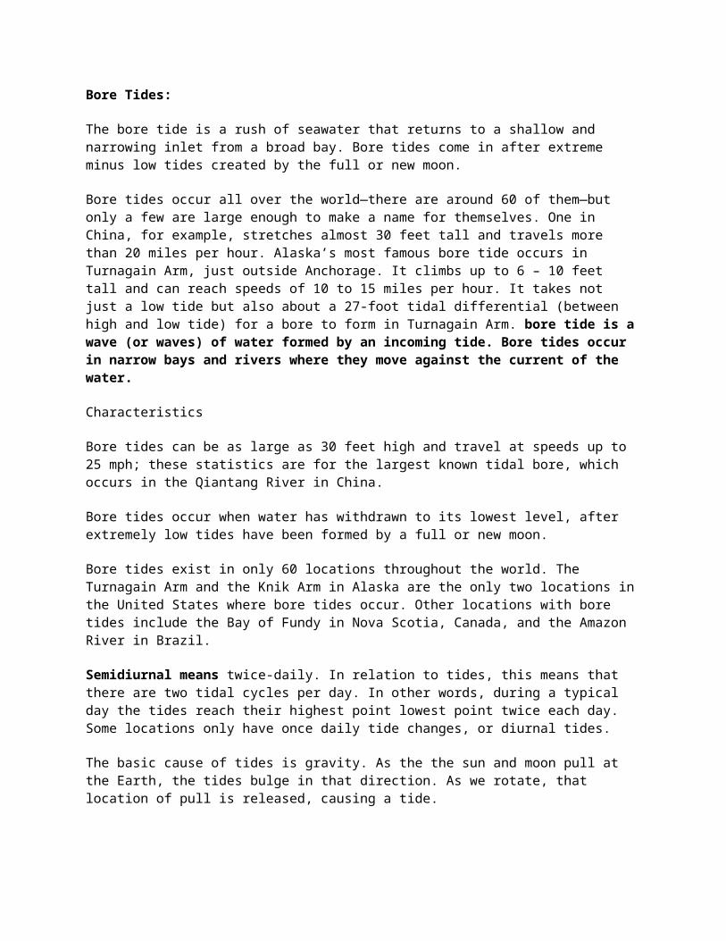
IMDG Code made mandatory
Amendments to SOLAS chapter VII (Carriage of Dangerous Goods) adopted in May 2002 make the IMDG Code mandatory from 1 Janaury 2004.
Also in May 2002, IMO adopted adopted the IMDG Code in a mandatory form - known as Amendment 31.
However, the provisions of the following parts of the Code will remain recommendatory:· chapter 1.3 (Training);· chapter 2.1 (Explosives, Introductory Notes 1 to 4 only);· chapter 2.3, section 2.3.3 (Determination of flashpoint only);· chapter 3.2 (columns 15 and 17 of the Dangerous Goods List only);· chapter 3.5 (Transport schedule for Class 7 radioactive material only), · chapter 5.4, section 5.4.5 (Multimodal dangerous goods form), insofar as layout of the form is concerned;· chapter 7.3 (Special requirements in the event of an incident and fire precautions involving dangerous goods only).
In practice, this means that from the legal point of view, the whole of the IMDG Code is made mandatory, but provisions of recommendatory nature are editorially expressed in the Code (e.g. using the word "should" instead of "shall") to clarify their status.
The mandatory IMDG Code incorporates certain changes relating to specific products, as well as relevant elements of the amendments to the UN Recommendations on the Transport of Dangerous Goods, Model Regulations adopted by the UN Committee of Experts on the Transport of Dangerous Goods at its twenty-first session in Geneva from 4 to 13 December 2000.
The amendments making the IMDG Code mandatory entered into force on 1 January 2004.
What's in itThe Code lays down basic principles; detailed recommendations for individual substances, materials and articles, and a number of recommendations for good operational practice including advice on terminology, packing, labelling, stowage, segregation and handling, and emergency response action. The two-volume Code is divided into seven parts:
Volume 1 (parts 1, 2 and 4-7 of the Code) contains sections on:
general provisions, definitions, training classification packing and tank provisions consignment procedures construction and testing of packagings, IBCs, large packagings, portable tanks and road tank
vehicles transport operations
Volume 2 contains:
the Dangerous Goods List (equivalent to the schedules in previous editions of the Code), presented in tabular format

limited quantities exceptions the Index appendices
The Supplement contains the following texts related to the IMDG Code:
EMS Guide Medical First Aid Guide Reporting Procedures Packing Cargo Transport Units Safe Use of Pesticides INF Code
Limited Quantity
Marine Pollutant
THESE PLAYCARDS MUST BE 100MM X 100 MM SIZE
SOLAS:
The International Convention for the Safety of Life at Sea (SOLAS), 1974, requires flag States to ensure that their ships comply with minimum safety standards in construction, equipment and operation. It includes articles setting out general obligations, etcetera, followed by an annex divided into twelve chapters. Of these, chapter five (often called 'SOLAS V') is the only one that applies to all vessels on the sea, including private yachts and small craft on local trips as well as to commercial vessels on international passages. Many countries have turned these international

requirements into national laws so that anybody on the sea who is in breach of SOLAS V requirements may find themselves subject to legal proceedings.
Chapter I – General Provisions Surveying the various types of ships and certifying that they meet the requirements of the
convention. Chapter II-1 – Construction – Subdivision and stability, machinery and electrical installations The subdivision of passenger ships into watertight compartments so that after damage to its hull,
a vessel will remain afloat and stable. Chapter II-2 – Fire protection, fire detection and fire extinction Fire safety provisions for all ships with detailed measures for passenger ships, cargo ships and
tankers. Chapter III – Life-saving appliances and arrangements Life-saving appliances and arrangements, including requirements for life boats, rescue boats and
life jackets according to type of ship. Chapter IV – Radio communications The Global Maritime Distress Safety System (GMDSS) requires passenger and cargo ships on
international voyages to carry radio equipment, including satellite Emergency Position Indicating Radio Beacons (EPIRBs) and Search and Rescue Transponders (SARTs).
Chapter V – Safety of navigation This chapter requires governments to ensure that all vessels are sufficiently and efficiently
manned from a safety point of view. It places requirements on all vessels regarding voyage and passage planning, expecting a careful assessment of any proposed voyages by all who put to sea. Every mariner must take account of all potential dangers to navigation, weather forecasts, tidal predictions, the competence of the crew, and all other relevant factors. It also adds an obligation for all vessels' masters to offer assistance to those in distress and controls the use of lifesaving signals with specific requirements regarding danger and distress messages. It is different to the other chapters, which apply to certain classes of commercial shipping, in that these requirements apply to all vessels and their crews, including yachts and private craft, on all voyages and trips including local ones.
Chapter VI – Carriage of Cargoes Requirements for the stowage and securing of all types of cargo and cargo containers except
liquids and gases in bulk. Chapter VII – Carriage of dangerous goods Requires the carriage of all kinds of dangerous goods to be in compliance with the International
Maritime Dangerous Goods Code (IMDG Code). Chapter VIII – Nuclear ships Nuclear powered ships are required, particularly concerning radiation hazards, to conform to the
Code of Safety for Nuclear Merchant Ships. Chapter IX – Management for the Safe Operation of Ships Requires every shipowner and any person or company that has assumed responsibility for a ship
to comply with the International Safety Management Code (ISM). Chapter X – Safety measures for high-speed craft Makes mandatory the International Code of Safety for High-Speed Craft (HSC Code). Chapter XI-1 – Special measures to enhance maritime safety

Requirements relating to organizations responsible for carrying out surveys and inspections, enhanced surveys, the ship identification number scheme, and operational requirements.
Chapter XI-2 – Special measures to enhance maritime security Includes the International Ship and Port Facility Security Code (ISPS Code). Confirms that the
role of the Master in maintaining the security of the ship is not, and cannot be, constrained by the Company, the charterer or any other person. Port facilities must carry out security assessments and develop, implement and review port facility security plans. Controls the delay, detention, restriction, or expulsion of a ship from a port. Requires that ships must have a ship security alert system, as well as detailing other measures and requirements.
Chapter XII – Additional safety measures for bulk carriers Specific structural requirements for bulk carriers over 150 meters in length.
TIMBER: Strength, pitch and tending of lashings
It is important to realize that Regulation 44 of the International Convention of Load Lines 1966, still applies to the 1991 IMO timber deck cargo Code, but the spacing of the trans- verse lashings within the Code, although still determined by height, does not permit an interpolation between cargo heights of 4m and 6m. The straightforward interpretation of such spacing applies to a compact stow of square-ended bundles (flush at both ends) or near square-ended bundles – in the following manner:
• Each package (along the sides, that is) shall be secured by at least two transverse lashings spaced 3m apart for heights not exceeding 4m above the weather-deck at sides.
• For heights above 4m the spacing shall be 1.5m above the weather-deck at sides.
• When timber in the outboard stow is in lengths less than 3.6m the spacing of the lashings shall be reduced as necessary (to comply with the requirement for each package to be secured by at least two transverse lashings).
• The stowage of timber deck cargo should be tight and compact. Where packages are involved, they should be square-ended (flush) at both ends so far as this is possible. Broken stowage and unused spaces should be avoided. There is no absolute requirement for uprights to be used for packaged timber cargo although some national administrations may insist on their use when lashing arrangements are not otherwise fully satisfactory. Bundles of regular form when stowed in ‘stepped-in’ truncated, pyramid fashion will not benefit from uprights, even if they are fitted. The IMO Code does not allow uprights to be used instead of lashings. Where uprights are used they are in addition to the full number of lashings properly pitched and of full strength.
• The use of uprights when carrying logs on deck is a necessary requirement, and it is most important always to rig and attach hog wires between such uprights. The uprights’ strength relies upon the weight of logs above the hog wires. This rule applies whenever hog wires are rigged – even with packaged timber. Never use uprights without rigging hog wires.
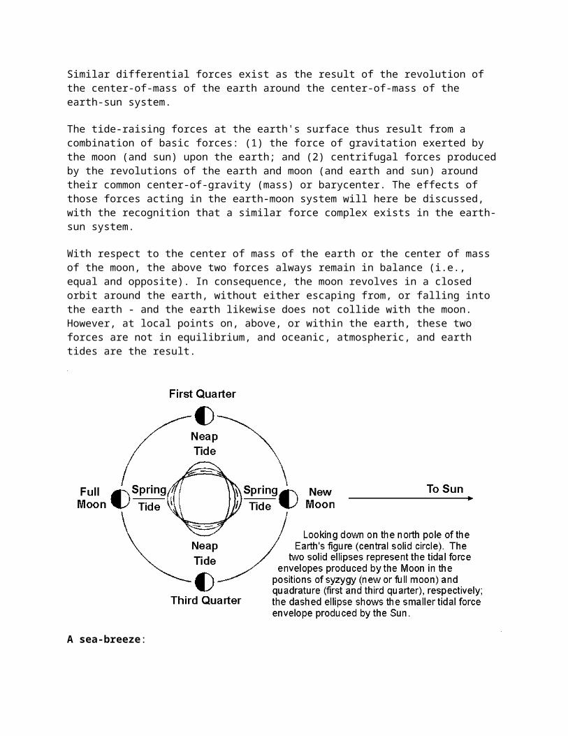
6 The lashings should be in accordance with chapter 4 of the Code and may comprise the following types:
1. Hog lashings are normally used over the second and third tiers and may be set "hand tight" between stanchions. The weight of the upper tiers when loaded on top of these wires will further tighten them.
2. Wire rope lashings are used in addition to chain lashings. Each of these may pass over the stow from side to side and loop completely around the uppermost tier. Turnbuckles are fitted in each lashing to provide means for tightening the lashing at sea.
3. Wiggle wires which are fitted in manner of a shoelace to tighten the stow. These wires are passed over the stow and continuously through a series of snatch blocks, held in place by foot wires. Turnbuckles are fitted from the top of the footwire into the wiggle wire in order to keep the lashings tight at sea.
4. Chain lashings which are passed over the top of the stow and secured to substantial padeyes or other securing points at the outboard extremities of the cargo. Turnbuckles are fitted in each lashing to provide means for tightening the lashing at sea.
What is woodpulp?There are various types of wood pulp. It is called “mechanical” when wood is reduced to small fibres in a mechanical grinding process. A variation of this is “thermo-mechanical” whereby the wood is first softened in a steaming process. These types of pulp are mainly used for newsprint and other so-called “wood containing” papers.“Chemical” pulp is obtained when cellulose fibres are separated from wood fibres in various types of cooking processes. Pure cellulose makes 40-45% of the dry weight of wood.Chemical pulp is stronger than mechanical pulp. The strength is also determined by the type of wood. Softwood, like spruce and pine, give 3-4 mm long fires, whereas hardwood fibres (birch, aspen, etc) are 1-1,5 mm long. Paper made from mechanical pulp is “yellowing’ very quickly like unpainted wood. Cellulose based paper does not fade.
Pulp Wood and Pit-Props
When these items are stowed in the manner described below, good compaction of the deck cargo can be

obtained. In the deck area clear of the line of hatches, the cargo should be stowed in the athwartship direction, canted inboard by some cargo laid fore and aft in the scuppers. At the centre of the stow, along the line of hatches, the cargo should be laid in the fore and aft direction when the wing cargo has reached hatch height. At the completion of loading, the cargo should have a level surface with a slight crown towards the centre.
To prevent the cargo from being washed out from below its lashings, it is recommended that nets or tarpaulins be used as follows:
The ends of each continuous section of deck cargo, if not stowed flush with the superstructure bulkhead, may be fitted with a net or tarpaulin stretched and secured over the athwartship vertical surface; over the forward end of each continuous section of deck cargo and in the waist of the ship the top surface may be fitted with a net or tarpaulin stretched and secured across the breadth of the cargo and brought down the outboard vertical sides to securing points at deck level.
A cofferdam
Is a temporary enclosure built within, or in pairs across, a body of water and constructed to allow the enclosed area to be pumped out, creating a dry work environment for the major work to proceed.
These cofferdams are typically a conventional embankment dam of both earth- and rock-fill, but concrete or some sheet piling also may be used.
The cofferdam is also used on occasion in the shipbuilding and ship repair industry, when it is not practical to put a ship in drydock for repair or alteration. An example of such an application is certain ship lengthening operations. In some cases a ship is actually cut in two while still in the water, and a new section of ship is floated in to lengthen the ship. Torch cutting of the hull is done inside a cofferdam attached directly to the hull of the ship, and is then detached before the hull sections are floated apart. The cofferdam is later replaced while the hull sections are welded together again. As expensive as this may be to accomplish, use of a drydock may be even more expensive.
Grain securing methods

Shifting Board
Longitudinal divisions (called shifting board), which must be grain tight may be fitted in both "filled" and "partly filled compartments".
In "filled compartments, they must extend downwards from the underside of the deck or hatchcovers, to a distance below the deckline of at least one-eighth the breadth of the compartment, or at least 0.6m below the surface of the grain after it has been assumed to shift through an angle of 15o. In a "partly filled compartment', the division, should extend both above and below the level of grain, to a distance of one-eighth the breadth of the compartment.
Saucers:
For the purpose of reducing the heeling moment a saucer may be used in place of a longitudinal division in way of a hatch opening only in a filled, trimmed, compartment as defined in A 2.2, except in the case of linseed and other seeds having similar properties, where a saucer may not be substituted for a longitudinal division. If a longitudinal division is provided, it shall meet the requirements of A 10.9. The depth of the saucer, measured from the bottom of the saucer to the deck line, shall be as follows:
1. For ships with a moulded breadth of up to 9.1 m, not less than 1.2 m.2. For ships with a moulded breadth of 18.3 m or more, not less than 1.8 m.3. For ships with a moulded breadth between 9.1 m and 18.3 m, the minimum depth of the saucer shall be calculated by interpolation.The top (mouth) of the saucer shall be formed by the underdeck structure in way of the hatchway, i.e. hatch side girders or coamings and hatch end beams. The saucer and hatchway above shall be completely filled with bagged grain or other suitable cargo laid down on a separation cloth or its equivalent and stowed tightly against adjacent structure so as to have a bearing contact with such structure to a depth equal to or greater than one half of the depth specified in A 14.2. If hull structure to provide such bearing surface is not available, the saucer shall be fixed in position by steel wire rope, chain, or double steel strapping as specified in A 17.1.4 and spaced not more than 2.4 m apart.
Bundling of bulk grain
As an alternative to filling the saucer in a filled, trimmed, compartment with bagged grain or other suitable cargo a bundle of bulk grain may be used provided that:
1.The dimensions and means for securing the bundle in place are the same as specified for a saucer in A 14.2 and A 14.3.
2. The saucer is lined with a material acceptable to the Administration having a tensile strength of not less than 2,687 N per 5 cm strip and which is provided with suitable means for securing at the top.
3. As an alternative to A 15.2, a material acceptable to the Administration having a tensile strength of not less than 1,344 N per 5 cm strip may be used if the saucer is constructed as follows:
Athwartship lashings acceptable to the Administration shall be placed inside the saucer formed in the bulk grain at intervals of not more than 2.4 m. These lashings shall be of sufficient length to permit being drawn up tight and secured at the top of the saucer.

Dunnage not less than 25 mm in thickness or other suitable material of equal strength and between 150 mm and 300 mm in width shall be placed fore and aft over these lashings to prevent the cutting or chafing of the material which shall be placed thereon to line the saucer.
The saucer shall be filled with bulk grain and secured at the top except that when using material approved under A 15.3 further dunnage shall be laid on top after lapping the material before the saucer is secured by setting up the lashings.If more than one sheet of material is used to line the saucer they shall be joined at the bottom either by sewing or by a double lap. The top of the saucer shall be coincidental with the bottom of the beams when these are in place and suitable general cargo or bulk grain may be placed between the beams on top of the saucer.
Overstowing arrangements
Where bagged grain or other suitable cargo is utilized for the purpose of securing partly filled compartments, the free grain surface shall be level and shall be covered with a separation cloth or equivalent or by a suitable platform. Such platform shall consist of bearers spaced not more than 1.2 m apart and 25 mm boards laid thereon spaced not more than 100 mm apart. Platforms may be constructed of other materials provided they are deemed by the Administration to be equivalent.
The platform or separation cloth shall be topped off with bagged grain tightly stowed and extending to a height of not less than one sixteenth of the maximum breadth of the free grain surface or 1.2 m, whichever is the greater. The bagged grain shall be carried in sound bags, which shall be well filled and securely closed.
Instead of bagged grain, other suitable cargo tightly stowed and exerting at least the same pressure as bagged grain stowed in accordance with A 16.2 may be used.
ACTIONS ON VESSEL AGROUND:Immediate actions:Take the con.Follow emergency procedure as per company emergency procedure manual, which should include:Sound general emergency alarm.Stop Engines.Announce by PA.Head count, look for casualty and establish communication.Close watertight doors.Activate SOPEP and take preventive actions in case of any oil pollution.Order chief officer for damage assessment.Water tight integrity of hull and subsequent breaches of same.Obtain sounding form all tanks, bilge’s, holdCondition of machinery space.Check hull for damage.Determine which way deep water lies.Visually inspect compartments where possibleSound bilge’s and tanks.Sound around the ship to find possible point of grounding.
Obtain following information from emergency teams:

Details casualties.Any fire risk
y Any
other information regarding associate problems.On the bridge, the command team will do the followings:
Determine possibility of refloating the ship and take appropriate actions:Calculate height of tide and time of rise and fall.Reduce draught of ship:De-ballastingJettisoning cargoUse main engines to maneuver.Obtain assistance from port authority, coast guard, salvage tugs.Subsequent legal and commercial actions:Try to minimize immediate danger such as pollution, fire etc.
While taking tug assistance, consider:LOF, if the danger imminent. (L’lyoids Open Form)Salvage contract if the situation permits.Use all available means of the ship to refloat the vessel.
Keep all records of incidents and actions. Appropriate records to be entered in:Deck log bookMovement bookEngine log bookTelegraph recorderEcho sounder graph.Used chartEntry to be made in official log book.Record of all damage and subsequent actions.Prepare a statement of fact of all the happenings.Prepare a note of protest, stating the facts only.If it is possible to refloat the vessel, consider the possibility of proceeding to voyage or deviating to port of refuge.Damage in FO tank as a result of groundingIn case of a damage in fuel tank, there is possibility of oil spill.
Maintained VHF watch.
Exhibit light / shapes and any appropriate sound signals.
Switch on deck lighting at night.Determine the vessel’s position.Obtain information on local currents and tides, particularly details of the rise and fall of the tide.Broadcast urgency or distress massage as required.
Inform the accident with positions and time to the following parties:Local authorities.Owners, charterers.P & I club.Make an accident report to MPA in the correct format.

SOPEP to be activated:Transfer fuel from damaged tank to other tank.Report to the appropriate authority.Obtain shore’s assistance to control spillage.Contain by booms/ mooring ropes, if the situation permits, by rescue boat.Use oil dispersal upon shore’s permission.Clean up oil if situation permits.In case of oil spill or FO tank damage, there is a subsequent risk of fire:Prepare fire fighting teams ready to fight fire.Remove all combustible materials from the scene.Fight fire if there is any.
Repair of damage:Proceed to port of refuge or next port for repair.Follow port of refuge procedures.Gas free the tank.Shift cargo/ combustible materials from adjacent tanks and holds.Prepare fire fighting equipments to fight probable fire.Damage control plan and damage control bookletProvide clear information onThe ship's water tight compartmentation.Equipments related to maintain the boundaries and effectiveness of the compartmentation
So that, in the event of damage to the ship causing flooding:Proper precaution can be taken to prevent progressive flooding through openings.Effective actions can be taken to control progressive flooding.Recover the ship's loss stability.Clear and easy to understand.Includes information directly related to damage control.Provided in working language of the ship.Translation to one of the official languages by SOLAS convention.
Damage control plan:
Scale: not less than 1 : 200.Isometric drawings for various purposes.Includes inboard profile, plan views of each deck and transverse sections to the extent necessary to show followings:Watertight boundaries of the ship.Locations and arrangement of cross flooding systems.Mechanical means to correct list due to flooding.Locations of all internal watertight closing appliances.Locations of internal ramps or doors acting as an extension of the collision bulkhead, their control.Locations of local and remote controls, position indicators and alarms.Locations of water tight compartments and water tight closing closing appliances, which are not allowed to be opened during navigation.Locations of all doors in the shell of the ship, position indicators and leakage detection.Locations of all watertight closing appliances in local subdivision boundaries above the bulkhead deck and on the lowest exposed weather deck, together with locations of controls with position indicators, if applicable.
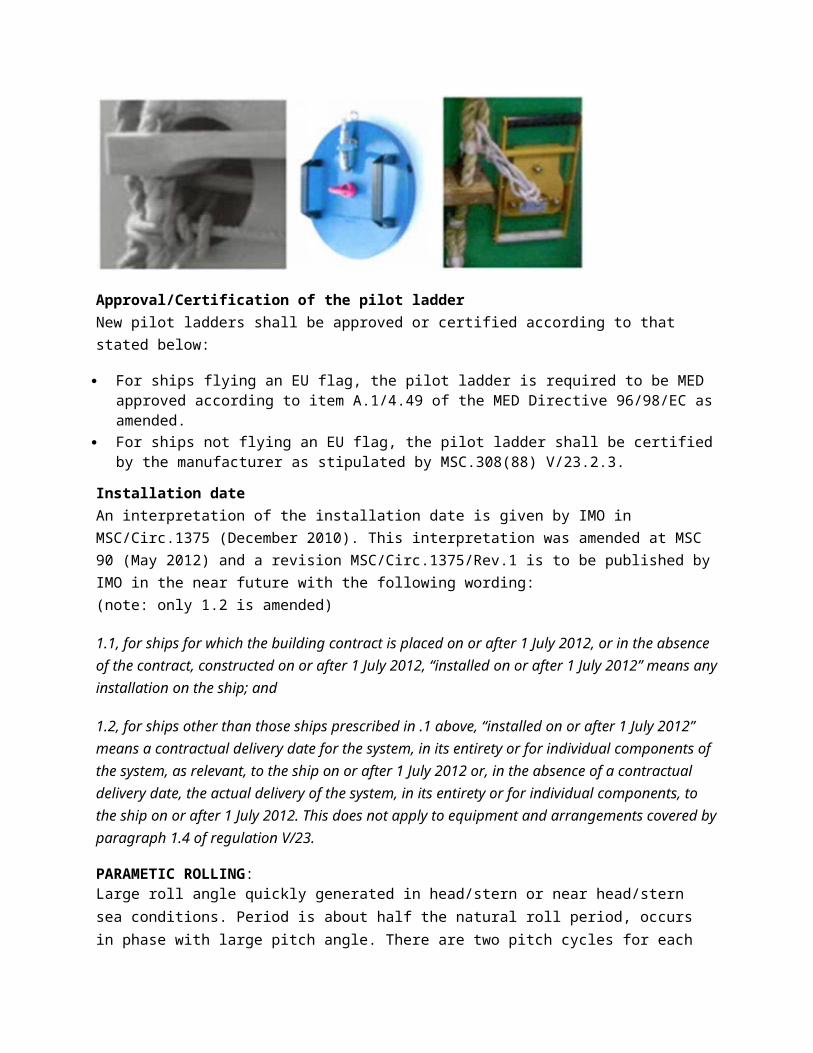
Location of bilge and ballast pumps, their control positions and associated valves.Pipes, ducts or tunnels, if any, through which progressive flooding has been accepted by administration.
Damage control booklet:
Information in damage control plan repeated in damage control booklet.Includes general instruction for controlling the effect of damage such as:Immediately closing all watertight and weather tight closing appliances.Establishing the locations and safety of persons onboard, sounding tanks and compartments to ascertain the extent of damage and repeated sounding to determine rates of flooding.Cautionary advice regarding the cause of any list and of liquid transfer operations to lessen list or trim, and the resulting effects of creating additional free surfaces and of initiating pumping operations to control the ingress of water.Contains additional details to the information shown on damage control plan, such as:Location of all sounding devices, tank vents and overflows which do not extend above the weather deck.Pump capacities and piping diagrams.Instruction of opening cross flooding systems.Means of accessing and escaping from water tight compartments below the bulkhead decks for use by damage control parties.Altering ship management and organizations to stand-by and coordinate assistance if required.Locations of non water tight openings with non automatic closing devices through which progressive flooding might occurs are indicated.Contains guidance on the possibility of non structural bulkheads and doors or other obstructions retarding the flow of entering seawater to cause at least temporary conditions of unsymmetrical flooding.If results of the subdivision and damage stability analyses are included, additional guidance are also provided to ensure that the ship's officers referring to that information are aware that the results are included only to assist them in estimating the ship's relative survivality.The guidance to identify criteria on which the analyses were based and clearly indicate that the initial action conditions of the ships loading extents and locations of damage, permeabilities, assumed for the analyses may have no correlation with the actual damaged condition of the ship.rdPassenger ships, damage control plan should be permanently exhibited on the navigation bridge, as well as the ships control room and equivalent.For cargo ships, the damage control plan should be permanently exhibited or readily available on the navigation bridge. Also, it should be permanently exhibited or readily available in the cargo control room.
Action in case of flooding:Sound all the tanks.Determine compartment flooded.Determine cause of flooding.Start bilge pump, portable welden pumps to pump out water from the flooded compartment.Asses rate of flooding.Check ship’s damage stability condition and loss of buoyancy. Refer to damage stability booklet.Determine reserve buoyancy, change in GM, trim, list.As per damage control plan, follow counter measures to control flooding.Keep monitoring soundings at regular intervals.Contain any oil spill, activate SOPEP in case of any oil spill.Transmit distress/urgency message as necessary if situation is uncontrollable.Proceed to a port of refuge if necessary and unsafe to continue voyage.Inform owner, charterer, P&I club, MPA.Inform port control/VTIS if necessary.Log down all timings, corrective actions taken.
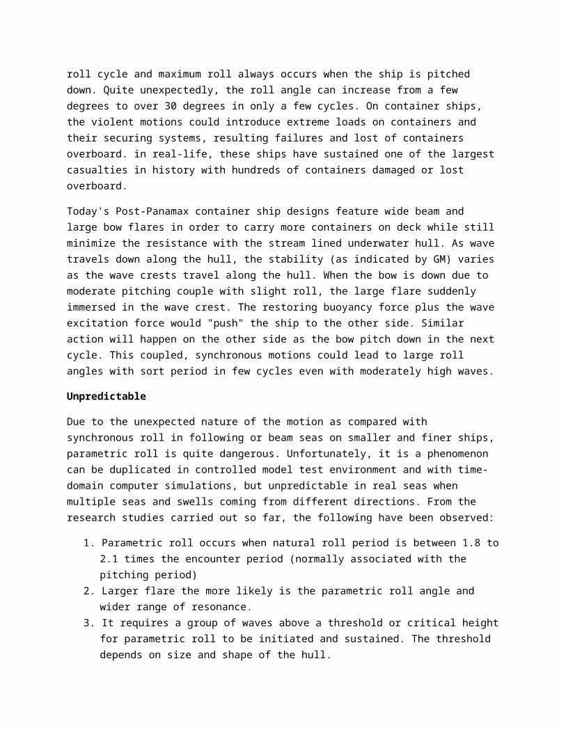
Lower lifeboat in heavy weather condition:
Preparation
Some steadying method to be used so that the life boat does not land hard against the ship side.Prevent the fall blocks to hit ship crew or lifeboat.Boat crews must wear life jacket, helmet, immersion suit in cold climate for rescuing operation.Sea quelling oil may be used to reduce the seas.Vessel to create a good lee. Wind to be on the opposite bow.Ship plugs.Lower lifeboat into the trough of a wave.On the next rising crest, release the hooks immediately and simultaneously.Cast off the painter once clear.Bear off the ship's side with tiller, oars or boat hook.Engine is started before the release of blocks and kept neutral.Once lifeboat is underway, tiller put against ship's side and with full throttle clear off the ship.
Precautions
Rig fenders, mattresses or mooring ropes to prevent the boat from being staved during an adverse roll.A cargo net, slung between davits and trailing in the water for crew to hang on in case the boat capsize alongside. It should not hamper the operation of the boat.The painter is rigged and kept tight throughout so as to keep the boat in position between the falls.The falls are loosely tied with a line, led to the deck and manned. When the boat is unhooked, the line line will steady the falls and prevent accidental contact with the boat crews.Once unhooked, the blocks should be taken up to avoid injuring the crews in lifeboat.Head to sea, or wind and sea on fine bow, at reduced speed:
Most suitable for deep draft vessels.Leeward drift is minimized (vessel is liable to sustain considerable pounding).Weather is allowed to pass over the vessel.The speed is considerably reduced.It affects the period of encounter of the oncoming wave formation and subsequently reduces pounding.Course and speed to be altered to remove possibility of hogging, sagging and synchronism.Situation becomes uncomfortable when violent pitching results in ‘racing propellers’, puts excessive stress on engines.Absolute control of rudder power is essential.Power should be reduced to minimum necessary to maintain steerage way and avoid undue stress on machinery.Two steering motors to be operational.Critical rpm to be avoided.Use of oil in bad weatherStorm oil may be used to reduce heavy seas.It prevents seas from breaking.Reduces hazards of bad weather.May be used to in heavy seas to:Turn the vessel.Lowering life boats.Rescue persons.Hove to.Towing operation.
Crossing a bar.Vegetable, animal or fish oil may be used.If not available, lubricating oil may be used.Fuel oil and crude oil not recommended, as they may congeal or may cause harm to men in water.A small amount of oil can quench a comparatively large sea area.About 200 Liters of oil can quell 4500 m2 sea area.To be distributed from both bows when heading into wind and seas.To be distributed from weather side when lying stopped or running with seas on the quarter.Should be used gradually.It may be done by:Trailing a punctured hose full of oilThrough a punctured canvas bag which have been weighted and filled with oil soaked cotton.Flushing through water closets.
Actions in a TRS:
Upon receiving the weather report, I will:Inform C/O, order him to secure deck.Inform C/E, order him to secure E/R.Plot storm’s position and observe its movement.Draw fan diagram todetermine safety sector. possible course to avoid storm.Ascertain ship’s position in relation to the stormBearing of storm’s center.From weather report.Buys Ballot’s law.Semi circle where the vessel is in.Path of the storm.Order OOW toupdate and monitor weather information and reports.Record hourly in log book:Wind direction and force.Wind shift.Barometric pressure.Swell direction and height.Arrange a FSA for storm.Strengthen the bridge watch and ensure proper look out.Change over to manual steering if auto pilot cannot cope up with weather condition.Continuous watch as visibility can be reduced.
Instruct C/O to:Check ship’s stability, draft, trim.Press up tanks to reduce FSE and windage areaPropeller and rudder sufficiently immersed to preventLoses of their efficiencyRacing of enginesExcessive vibrationTake heavyweather precaution.I will remain outside of a radius of 200nm from storm center. If necessary:Alter course to keep away from storm

Heave to, to let the storm pass by a safe distanceReduce speed, if helps to avoid storm.Ensure vessel does not roll or pitch heavily, as it may causeMay be damage to cargoShifting of cargoDamage to ship’s structureDamage to deck equipments, cranes, derricks etc.All preparations for heavy weather to be entered in official log book and deck log book.
keep in mind:Storm can be erratic and different from weather forecast.Engine and any navigational/ communication equipment may fail any time.Ensure personnel get enough rest, considering fatigue due to storm.No body to go on deck without C/O’s permission.Instruct C/E to check steering gear and M/E performance regularly.Inform following parties about storm and amended ETA:Owner.Charterer.Agent of next port.
When master is not obliged to assist ?
When vessel is unable to rescue, e.g., vessel does not have enough bunker.When it is unreasonable e.g., the distance is so far the vessel will rake 4/5 days to rescue, but that place is a traffic dense place and survivors may be easily picked by other vessel.When it is unnecessary, e.g., a man overboard in ice/cold region and distance is so far that vessel will take long time to go there. So it is impossible for a man to survive in this situation.If the vessel have not been requisitioned by the master of distress vessel, but more other ships have been requisitioned and they are complying with the requisition.The master of a requisitioned vessel will be released from the obligation if he is informed by the distressed vessel or by the search and rescue service or by the master of another vessel which has reached the distressed position that assistance is no longer required.
Apparent period
The apparent period of wave is the time interval between the passage of two successive crests relative to a shipborne observer.It is sometimes called period of encounter.
Panting
Tendency of the bow plating and to a lesser extent the stern plating to work in and out when the ship is pitching.Fore and aft regions of the vessel are extra strengthen by thicker plating, panting beams and stringers, reduced frame spacing in designed to withstand panting stress.
Backing
Change of true wind direction to an anti-clockwise direction.
Veering
Change of true wind to a clockwise direction.
Following and quartering seas
Following seas
Occurs when vessel running before the sea.Sea comes from the stern.The ship encounters various dangerous phenomena.
Quartering seas
Occurs when vessel running before the sea.Sea comes from the quarter.The ship encounters various dangerous phenomena.
In a following or quartering sea, following dangerous phenomenon may occur:
Pooping
Breaking of rising wave over the stern in poop deck area.Develops when bad weather is directly from stern.Vessels with less freeboard may suffer from popping.Occurs when a vessel falls into the trough of a wave and does not rise with it.It may occur if the vessel falls as the wave is rising.Causes following wave to break over the stern or poop deck areas.
Result:
May cause considerable damage to stern area.Damage to propeller and rudder due to severe buffeting.Engine room can be flooded if the openings which face aft are not properly secured.
Corrective actions:
Occurs when velocity of sea is equal to or greater than ship's speed.Alter course and head sea.
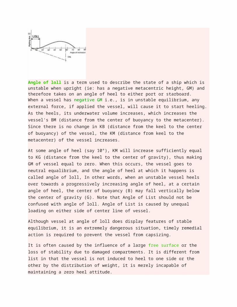
Surf riding
Occurs when a ship situated on a stiff forefront of high wave in a following or quartering sea.Vessel and waves have equal velocities.Vessel may be accelerated.Vessel rides on advancing wave slope.This phenomenon is called surf riding.
Result:
Vessel slewed violently (broach-to).Vessel heeled over and swamped.
Action:
Critical speed for surf riding is considered (1.8ÖL)/cos(180°-α) knots.Surf riding/broaching-to may occur when angle of encounter 135°<α<225°.To avoid surf riding, speed/course or both to be taken outside the dangerous region.
Broach to
May occur when a ship is surf ridden in a following or quartering sea.The vessel is slewed violently.Ship heels suddenly and unexpectedly to a large angle.
Result:
Positive stability disappears to the existing angle of heel.Vessel may cause a vessel to capsize due to sudden change of heel and heading.
Action:
Reduce speed below 1.8ÖL knots.A marginal zone (1.4ÖL to 1.8ÖL) below critical speed may cause a large surging motion (broach to). Speed to be reduced below 1.4ÖL in the case.
Synchronous rolling
Large rolling motions may be excited when natural rolling period of a ship coincides with the encounter wave period.It may happen in following and quartering sea.It happens when natural roll period is longer due to marginal transverse stability.Occurs when rolling or pitching period is equal or nearly equal to the apparent period of wave.
Synchronism may be synchronized rolling or synchronized pitching.
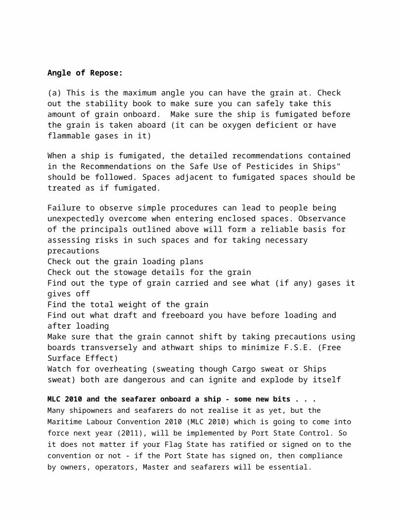
Parametric rolling
Occurs in a following or quartering sea.Occurs when period of encounter is approximately equal to the natural rolling period of the ship.Occurs particularly if initial metacentric height height is small and natural roll period is very long.Unstable and large amplitude roll motion takes place.May occur in head and bow seas.Result: Unstable and large rolling motion takes place.Action: Reduction of speed.
Combination of various dangerous phenomenon
May occur in a following or quartering sea.Various detrimental factors may affect ship's dynamic behavior.These factors are:Additional heeling moment due to deck water.Water shipping and trapped on deck.Cargo shift.The factors may be occur with other dangerous phenomenon.They may create extremely dangerous combination to capsize the ship.
Successive wave attack
Occurs when ship's speed component in the wave direction is nearly equal to the wave group velocity.It is equal to the half of phase velocity of the dominant wave component.The ship is attacked successively by high waves.Expectable maximum wave height can reach almost twice of observed wave height.May be evident when average wave length is larger than 0.8L, significant wave height is larger than 0.04L.
Result:
Reduction of intact stability.Synchronous rolling.Parametric rolling.Combination of various dangerous phenomena.Vessel may capsize.
Action:
Reduce ship speed to go out of dangerous zone.Combination of appropriate speed reduction with slight course change.
Synchronized rolling:How to determine:
Vessel rolling heavily.

There is no period of lull, rolling angle is almost same or increasing in every roll.Vessel is encountered by the same phase of wave almost all the times.
Precautions:
Synchronized rolling to be determined immediately.Occurs when the period of roll is equal or nearly equal to the apparent period of encountered wave.A very dangerous and undesirable condition.Successive waves tend to increase the angle of roll of the vessel, thereby produce danger of capsize.More dangerous in small vessels or vessels with low stability.Most dangerous when a beam sea is experienced and the ship reaches a greater maximum inclination at each trough and crest of wave.Danger of cargo shift.Danger of damage to vessel.Corrective actions:Change apparent period of waves by:Alteration of courseAlteration of speedChange vessels rolling period by changing GMBy ballastingBy deballastingShifting of ballast, FO, FW etc and changing transverse position of G.
Preference:prefer standing moor. Because:
SaferMore control on the ship.The anchor is let go after vessel stopped.There is no possibility of damage due to anchoring at headway.
Baltic moor
Employed alongside a quay.Used when construction of the berth is no sufficiently strong enough to withstand ranging in bad weather.Can be employed for berthing a vessel in an onshore gale wind.
Procedures:
For a average size merchant ship, a 25-30mm wire is passed from the after ends on the poop, along the offshore side, outside and clear of everything.Offshore anchor is cockbilled.A man is send overside on a chair to secure the wire with the anchor, preferably at the shackle.The wire is secured with ship's rail by sail twine in bights.The aft end of the wire is sent to a wrapping barrel, ready for heaving slack wire.When the stem is abreast the position of the quay where the bridge will be positioned, the anchor is let go.The vessel is still on headway.About half a ship's length of the cable, the cable is surged and then snubbed.

The wire is hove-in aft.The onshore wind will drift the vessel to the berth.The scope of the cable and the wire is adjusted and veered slowly until the ship is alongside.Distance of ship, length of cable and wire must be considered.Normally, the anchor is dropped at a distance 2/3 shackles length of the cable from the quay, which may vary depending on the prevailing circumstance.
Mediterranean moor
Method of securing a vessel stern to the berth.Both the anchors leading ahead to hold the bow in position.The approach should preferably be made with the berth on port side.The starboard anchor is let go about two ships length from the berth(1).The vessel continues to move ahead.Starboard helm is applied and the cable is veered.The engines are then put astern and the port anchor is let go (2).As the vessel comes astern, transverse thrust swings the stern to port towards the berth.Stern lines are sent away.
SHALLOW WATER EFFECTS:When the depth of water is less comparing to the draft of the ship. The hydrodynamic forces affect the ship handlings in different ways. The effects become evident when the depth of water is less than 1.5 times of the draft of the ship.In shallow waters, following effects may be evident:
Sluggish movement:
As the hull moves along the water, the water which is displaced is not instantly replaced by surrounding water.A partial vacuum is created.The vessel takes longer to answer helm.Response to engine movement becomes sluggish.Speed reduces.
Vibration:
In shallow water vibrations set up.It becomes very difficult to correct a yaw or sheer with any degree of rapidity.
Steering:
Steering becomes erratic.Rate of turning is reduced.Turning circle becomes larger.Loss of speed due to turning is less in shallow water.
Smelling the ground:
Occurs when a ship is nearing an extremely shallow depth of water, such as a shoal.The ship likely to take a sudden sheer.The sheer is first towards the shallow, then violently away from it.The movements of a sluggish ship may suddenly become astonishingly lively.These effects are called smelling the ground.
Squat:
Water displaced by the hull is not easily replaced.Bow wave and stern wave increase in height.Trough becomes deeper and after part is drawn downwards.Under keel clearance decreases.This effect is called squat.
Factors governing squat:Squat varies on the following factors:
Ship's speed: Squat is directly proportional to the square of speed.
Squat V2 (V=speed in knots)
Block co-efficient: Squat directly varies with CB.Blockage factor (S): It is the ratio between cross section of the vessel and cross section of the canal or river. Squat varies with blockage factor as.
Squat S0.81
So, in confined water, squat is more than in open water.
Squat may be calculated by the following simplified formulae:
Squat = (CB X V2 ) / 100 (In open waters)Squat = 2 X (CB X V2 ) / 100 (In confined waters)Precaution
Squat may cause grounding in spite of enough UKC.Squat to be calculated beforehand.Speed to be reduced to reduce squat.While determining UKC, squat for the speed to be taken into consideration.
Bow cushion and bank suction effect:
Occurs in narrow channels near proximities of banks.There is a tendency for the bow of a ship to be pushed away from the bank, called bow cushion.The ship moves bodily towards the bank, which appears at the stern, called bank suction.Caused by the restricted flow of water on the bank's side.Velocity of water to the bank increases and pressure reduces.Results in drop of water level towards the bank.As a result, a thrust is set up towards bank.A vessel approaching to the bank will have to apply helm to the bank and reduce speed to prevent the sheer from developing.
Canal effect:
Water level drops towards a bank.Vessel heels towards bank to displace constant volume.Varies as the square of speed.Corrective helm to be applied.
Factors of ice accretion

If wind force increases above force 6, the rate of ice accretion increases because:
Wind chill factor increases.Increase of shipping spraysAir temperature falls below -2°CSea temperature decreasesShipping seas and sprays increases
Excessive ship's speedUnsuitable ship's courseRate of ice accretion on a slow moving ship with the wind ahead or on the beam, given wind and sea temperature, can be estimated using "Icing Nomograms" given in mariner's handbook.
Cold weather precautions
Provide suitable worm clothingOrganize and brief bridge team prior to entry into the ice regarding:
Indications of presence of iceNot to be overexposed to extreme coldLook outs need to be rotated at short intervalReport to master on sighting iceRegular radar watch in appropriate rangeSecond watch keeperObtain up to date ice reports and ensure that ice limits are entered in the chart, plot occasional icebergs.Change over to manual steering until the vessel is clear of ice region. Helmsman to report D/O if loss of steering.Instruct C/E to regularly check the followings:
Steering gearHeating arrangements of steering gearsTo check viscosity of hydraulic oil for all cranes, winches and boat engines, if necessary, renew.Inform all departmentsCheck all navigation equipements are in satisfactory conditions.Check navigation lights, search light and sound signaling appliances
Instruct C/O the followings:
The ship has sufficient stabilityShip should be sufficiently trimmed that propeller tips are well submerged.Ballast tanks, FW tanks, life boat FW tanks not to press up full, keep allowance for expansion. Especially above water line tanks. Calculate free surface effect.Drain fire lines on deck.All deck scuppers to be cleared to prevent water trapping on deck.Cover deck machinery and controls with canvas.If steam windlass, run slowly.Cranes/ derricks to be freeze, to prevent this, they should be topped/slewed at regular intervals.

Hawse pipes/ sparling pipe covers are in position.Rig life lines on deck as may become slipperyAll LSA/FFA in satisfactory condition and ready for immediate use.
General procedures and precautions in dry dock:
Before entry:
Check the stability of the vessel, especially during critical period.Check the vessel at required draft.No list.Prepare mooring lines.Unused mooring lines stowed.Standby for dock master and dock mooring gang.Proper flags displayed as required.Free surface effects minimum.Movable weights to be secured.Ship power, fire main, fresh water, telephone connections to be ready.Logs off/ retracted.Off echo sounders.Overboard discharges to be shut.Gangway/ accommodation ladders to be stowed.Anchors stowed and secured.Crews standby to assist moorings as required.
While entering:
Times of the followings to be logged down:When vessel enters dock.When the gate closedWhen pumping out commenced.When vessel sewedWhen pump out completed.
After vessel docked:
Tanks and bilge soundings throughout the vessel.Records to be kept with copy to dock-master.Hull high pressure wash as the level goes down.Initial inspection of the hull to be done as soon as possible:The extend of the hull damage if any.The extend of the rudder and propeller damageSuitable and efficient shoring arrangementsSuitable and efficient keel blocksPlugs to be removed, if draining of the tanks to be required.All removed plugs to be in safe custody of C/O.Bridge equipments, gyro shut down, heading recorded.State the preparation of a vessel for dry docking.

Arrange a meeting with the heads of departments. Inform them about the dry docking plan. Inform them about:The dry dock, particulars of dry dock, if any, expected date of dry dock etc.Instruct the chief engineer / chief officer to prepare a comprehensive dry docking and repair list.Arrange another meeting with the head of the departments to go through the repair list respectively.Determine which repairs can be done onboard by ship’s personnel.Check there is no overlapping of repairs between various departments.Recompile repair list of both departments.Prepare an official repair list, include proper photocopies of plans or diagrams of parts to repair.Send the repair list to office. Also send the list of repairs to be done by ship’s personnel.Ensure all plans are onboard.Approved list from head office will be send back to the ship.Heads of departments to have copy of repair lists.Heads of departments to brief crew members regarding dry dock repairs.Safety committee also to be involved regarding dry dock repairs.The surveys due and to be done in dry dock.Required preparation for surveys.Any modification to be carried out.Order the necessary stores, materials for repair jobs by ship's crew.Ask to company for extra officer if deem necessary.Assign duties for officers and brief them about safety and security of the vessel and maintaining efficient watch at all times.For chief officer, overall supervision of deck work list, safety and organization of crew for dry dock and survey.For 2nd officer, supervision of hull cleaning and painting and to keep watch under c/o's instruction.For 3rd officer, in charge for safety while in dry dock and to keep watch under c/o's instruction.Designate personnel for fire patrol and gangway watch.Designate personnel for filling FW and disposal of garbage.Instruct c/o to brief the crews on general safety requirement, dock and regulations to be followed and procedures to be taken in case of emergency / accident.
Stability of the ship to be calculated before entering. Following things to be considered:
The GM of the ship, maximum loss of GM during critical period.Vessel to be stable throughout the process.Trim of the ship should be adequate.Vessel should be upright.Amount of ballast, FW, FO, cargo onboard and their distribution.Cranes to be stowed to avoid obstruction to dry dock cranes. High antennas to be lowered.Lifebuoys to be removed from deck to avoid over painting.Off-hire time and position to be ascertained and logged (if time chartered).
Critical period:The period since the keel first touches the block until the vessel takes blocks overall.An upthrust is caused by the blocks, denoted by "P".P at any instant can be calculated by the following formula:P = TPC X Change in mean draft in cm.
P is maximum at the instant before vessel takes blocks overall. It can be calculated as:P = MCTC X t / l { t = trim in cm, l = dist of CF from AP}
Due to the upthrust, the vessel reduces its GM.The G moves UP, thereby GM is reduced.M moves down to M', thereby GM is reduced.Shift of G (Center of gravity) or M (Transverse metacenter) may be calculated as:
GG' = (P X KG)/(W - P)MM' = (P X KM)/W
The danger is, due to subsequent loss of GM, the vessel may lose positive stability and may capsize.Maximum loss of GM to be calculated beforehand.It is dangerous if negative GM occurs in dry dock.
What things you will check before refloating in dry dock?
Before:
Ship’s stability condition to be kept as close as to that when she is entering in the dry dock.Enough GM and positive stability during critical period.No changes of weight to be made without the consent of the dock-master.Movable weights to be secured.Minimum free surface effect and no list.All plugs to be secured.Anchors stowed and secured.All overboard discharges secured.Anodes fitted.All pipings, cable connections with shore disconnected.Start gyro, check heading.While refloating:Inform E/R when flooding dock.Check for water tightness.Sound all tanks.
Following times to be logged down:
Flooding commencedVessel floatedDock gate openedVessel left dock.
After refloating:
Check operation of all equipments.General cleaning and washingNormal sailing checklist.Check water tight integrity of the vessel
MINIMIZE RISK OF FIRE:
Fire is one of the greatest maritime perils at sea.A few good practices can reduce risk of fire.Fire safety objectives onboard a ship are:Prevent the occurrence of fire and explosion.
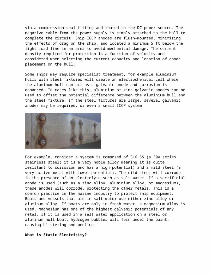
Reduce the risk to life caused by fire.Reduce the risk of damage to ship, cargo or environment caused by fire.Contain, control and suppress fire and explosion in the compartment of origin.Provide adequate and readily accessible means of escape for passengers and crews.
Procedures:
Cleanliness and good housekeeping.Avoid accumulation of oil, especially in engine room.Settling tanks and other oil tanks must not overflow.Any oil leak must be treated immediately.Discarded cotton waste and cleaning rags should be put into metal containers which are emptied regularly.All the equipments used in hazardous areas must be approved type.Smoking regulations to be followed.All fire fighting equipments should be well maintained and ready for immediate use.Especial precaution to be taken when doing hot work or any operation which renders a risk of fire.Electric circuits should not be overloaded.Unauthorized electrical equipments should not be used onboard.All electrical wirings and fittings should be of approved type and well maintained.Clothing should not be left for drying near any hot electrical equipment.
Especial measures in port:
Risk of fire is greater especially when ship in port.Extra precaution to be observed when hot works are being carried and flammable materials being loaded or discharged.Before any hot work, inflammable materials must be removed from adjacent spaces.During hot work, fire fighting appliances should be kept ready for immediate use.Smoking regulations to be strictly observed.Unauthorized visitors should not be allowed.Warnings and notices to be posted for not smoking, especially in special types of ships.
Fire in cargo hold at sea
Immediate actions:Sound fire alarmAnnounce by PAInform E/Rreduce speedActivate ship's contingency plan for fire.Muster in the emergency stationMuster as per emergency teamCarry out head countCheck if any casualtyEstablish communication between emergency teams and bridge.Command team will:Check vessel’s positionCheck weather condition, wind direction, forceSuit vessel’s course appropriate for minimum wind effect if traffic condition permits.

Alter courseReduce speedRecord all the events and steps takenSend urgency or distress message depending on the extent of fire.In-charge of emergency team to ensureAny casualty.Prepare fire fighting team for fighting fire.Investigate location and nature of fire, inform to bridge.Rig fire hoses for boundary cooling.Seal off the hold, close all ventilators, flaps, blowers, fire doors.Cut off electrical supply to the hold.Back up team will:Ensure fire men’s outfit, BA sets & spare bottles are readily available.Support team will:Prepare life boats for lowering.Take care of casualty.C/E will ensure:Start emergency fire pumpStart emergency generatorMaintain fire pump pressureI’ll decide the best way to fight fire based on all available information and instruct C/O to fight fire
accordingly:If there is small fire, use portable fire extinguishers depending on the type of fire.In case of big fire:Send two men donning firemen’s outfit to fight the fire with fire/dry powder hose.They are to be supported by two men, with fire hoses used to produce protective curtain.Back up team to continue boundary cooling.Check adjacent compartments if there is sign of spreading fire.If fire is uncontrollable and deep seated:Flood the hold with CO2 as per ship's fire plan.If hold contains nitrates, sulfates or explosives, flood hold with water.Never open hatch. Entry of air may cause flash back.Consider loss of stability while using water to fight fire.Refer to damage stability booklet for loss of stability.Continuously monitor temperature of affected area and its surroundings.Maintain fire watch when fire is extinguished.Cancel distress/urgency message.Follow up actions:Report details to owner, charterer, P&I club.Send an accident report to MPA.Prepare a note of protest to save owner's interest, stating the facts only.Prepare a master’s report that includes:When fire started.Extent of fire.Details of damage to cargo due to fire.Any personnel injury.Attempts made to extinguish fire.Time taken to extinguish fire.
Hydrolants and hydropacs:
US radio navigational warnings.Originated by DMAHC (Defence Mapping Agency Hydrographic Center).Broadcasted twice daily via US navy and US coastguard radio stations.Published in Sec-3 of US notices to mariners.
Hydrolant areas:
North Atlantic oceanSouth Atlantic oceanCaribbean seasGulf of MexicoMediterranean seasNorth seasContegious areas.
Hydropac areas:
Pacific OceanIndian OceanSouth China SeasContagious area
Calling master as per STCW-95If restricted visibility is encountered or expected.
If traffic conditions or movements of other ships are causing concern.
If difficulty is experienced in maintaining course.
On failure to sight land, a navigation mark or obtain soundings by the expected time.
If, unexpectedly, land or a navigation mark is sighted or change in sounding occurs.
On the breakdown of the engines, steering gear, or any essential navigational equipment.
In heavy weather, if in any doubt about the possibility of weather damage.
If the ship meets any hazard to navigation, such as ice or derelicts.
In any other emergency or situation in which the OOW is in any doubt.
Continuous Synopsis Record - CSR
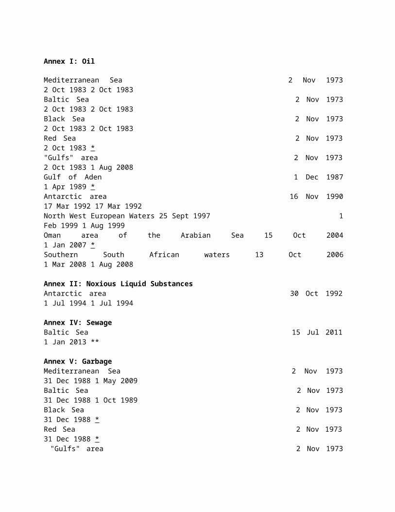
The Continuous Synopsis Record is intended to provide an on-board record of the history of the ship with respect to the information recorded therein.The Continuous Synopsis Record shall be issued by the AdministrationShall contain, at least, the following information:The name of the State whose flag the ship is entitled to fly;The date on which the ship was registered with that State;The ship’s identification number in accordance with regulation (IMO Number)The name of the ship;The port at which the ship is registered;The name of the registered owner(s) and their registered address(es);The name of the registered bareboat charterer(s) and their registered address(es), if applicable;The name of the Company, as defined in regulation IX/1, its registered address and the address(es) from where it carries out the safety-management activities;The name of all classification society(ies) with which the ship is classed;The name of the Administration or of the Contracting Government or of the recognized organization which has issued the Document of Compliance.The name of the Administration or of the Contracting Government or of the recognized organization that has issued the Safety Management CertificateThe name of the Administration or of the Contracting Government or of the recognized security organization thathas issued the International Ship Security Certificate andThe date on which the ship ceased to be registered with that State.Any changes relating to the entries shall be recorded in the Continuous Synopsis Record so as to provide updated and current information together with the history of the changes.The Continuous Synopsis Record shall be kept on board the ship and shall be available for inspection at all times.
IAMSAR
SC (SAR Coordinator):
Country's top SAR manager.Develops SAR and SAR training policies.Establishes RCCs and Rescue Sub Centers.Provides for, arranges and manages SAR facilities of the country.
SMC (SAR Mission Coordinator):
Appointed for and oversees each SAR each SAR operation under guidance of SC(SAR Coordinator).Normally this duty is undertaken by the head of RCC.
Duties of SMC
Obtain all data on emergency.Ascertain type of emergency equipment carried by distress craft.Obtain update on weather /sea conditions.Locate shipping in search areas.Plot search areas and methods.
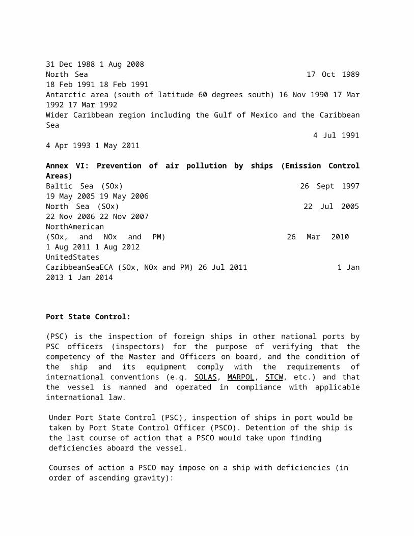
Maintain radio listening watch.Allocate radio frequencies.Designate OSC and CSS.Dispatch delivery of survival supplies to survivors.Maintain record of events.Record results of searched areas.Monitor SAR units engaged eg. helicopter flying hours, etc.
OSC (On scene coordinator):
Person coordinates SAR facilities working at the scene.Designated by SMC.The person in charge of the first facility to arrive on scene normally assume OSC function unless SMC arranges relief.
Who can be an OSC:
When two or more SAR facilities conduct operations together, the SMC should designate an OSC.If this is not practicable, facilities involved should designate, by mutual agreement, an OSC.This should be done as early as practicable and preferably before arrival within the search area.Until an OSC has been designated, the first facility arriving at the scene should assume the duties of an OSC.When deciding how much responsibility to delegate to the OSC, the SMC normally considers the communications and personnel capabilities of the facilities involved.
Duties of OSC
Co-ordinate operations of all SAR facilities on-scene.Obtains the search action plan from the SMC.Plan the search or rescue operation, if no plan is otherwise available.Modify the search action or rescue action plan as the situation on- scene dictates, keeping the SMC advised.Co-ordinate on-scene communications.Monitor the performance of other participating facilities.Ensure operations are conducted safely, paying particular attention to maintaining safe separations among all facilities, both surface and air.Make periodic situation reports (SITREPs) to the SMC.Maintain a detailed record of the operation:On-scene arrival and departure times of SAR facilities, other vessels and aircraft engaged in operationAreas searchedTrack spacing usedSightings and leads reportedActions takenResult obtained.Advise the SMC to release facilities no longer required.Report the number and names of survivors to the SMC.Provide the SMC with the names and designations of facilities with survivors aboard.Report which survivors are each facility.Request additional SMC assistance when necessary (for example, medical evacuation of seriously injured

survivors).
SITREP (SAR Situation report)
The standard SITREP format may be found in IAMSAR Vol-3, appendix D.SITREP should include but not be limited to:Weather and sea conditionsThe results of search to dateAny actions takenAny future plans or recommendations.
Solas CH-XI-I, Regulation-5
Maritime zonesTerritorial waters
The sovereignty of a coastal State extends, beyond its land territory and internal waters and, in the case of an archipelagic State, its archipelagic waters, to an adjacent belt of sea, described as the territorial sea.This sovereignty extends to the air space over the territorial sea as well as to its bed and subsoil.The sovereignty over the territorial sea is exercised subject to this Convention and to other rules of international law.Every State has the right to establish the breadth of its territorial sea up to a limit not exceeding 12 nautical miles, measured from baselines determined in accordance with UNCLOS.A list of known claims of territorial seas published in annual notices to mariners No-12.
Annual summaries of Admiralty Notices To mariners Sec-12.
Contiguous zone
In a zone contiguous to its territorial sea, described as the contiguous zone, the coastal State may exercise the control necessary to:Prevent infringement of its customs, fiscal, immigration or sanitary laws and regulations within its territory or territorial sea;Punish infringement of the above laws and regulations committed within its territory or territorial sea.The contiguous zone may not extend beyond 24 nautical miles from the baselines from which the breadth of the territorial sea is measured.
Exclusive Economic Zone - EEZ
The exclusive economic zone is an area beyond and adjacent to the territorial sea.In the exclusive economic zone, the coastal State has:Sovereign rights for the purpose of exploring and exploiting, conserving and managing the natural resources, whether living or non-living, of the waters superjacent to the seabed and of the seabed and its subsoil, and with regard to other activities for the economic exploitation and exploration of the zone, such as the production of energy from the water, currents and winds;Jurisdiction as provided for in the relevant provisions of this Convention with regard to:(i) the establishment and use of artificial islands, installations and structures;(ii) marine scientific research;(iii) the protection and preservation of the marine environment;The exclusive economic zone shall not extend beyond 200 nautical miles from the baselines from which

the breadth of the territorial sea is measured.A list of known claims of EEZ published in annual notices to mariners No-12.
Continental shelf
The continental shelf of a coastal State comprises the seabed and subsoil of the submarine areas that extend beyond its territorial sea throughout the natural prolongation of its land territory to the outer edge of the continental margin, or to a distance of 200 nautical miles from the baselines from which the breadth of the territorial sea is measured where the outer edge of the continental margin does not extend up to that distance.The continental margin comprises the submerged prolongation of the land mass of the coastal State, and consists of the seabed and subsoil of the shelf, the slope and the rise. It does not include the deep ocean floor with its oceanic ridges or the subsoil thereof.For the purposes of this Convention, the coastal State shall establish the outer edge of the continental margin wherever the margin extends beyond 200 nautical miles from the baselines.The fixed points comprising the line of the outer limits of the continental shelf on the seabed, either shall not exceed 350 nautical miles from the baselines or shall not exceed 100 nautical miles from the 2,500 meter isobath, which is a line connecting the depth of 2,500 metres.The coastal State exercises over the continental shelf sovereign rights for the purpose of exploring it and exploiting its natural resources.The rights are exclusive in the sense that if the coastal State does not explore the continental shelf or exploit its natural resources, no one may undertake these activities without the express consent of the coastal State.The natural resources referred to in this Part consist of the mineral and other non-living resources of the seabed and subsoil together with living organisms belonging to sedentary species.
High sea
All parts of the sea that are not included in the exclusive economic zone, in the territorial sea or in the internal waters of a State, or in the archipelagic waters of an archipelagic State.The high seas are open to all States, whether coastal or land-locked.Freedom of the high seas:Freedom of navigation;Freedom of overflight;Freedom to lay submarine cables and pipelines, subject to Part VI of UNCLOS.Freedom to construct artificial islands and other installations permitted under international law, subject to Part VI of UNCLOS;Freedom of fishing, subject to the conditions laid down in section 2 of UNCLOS;Freedom of scientific research, subject to Parts VI and XIII of UNCLOS.No State may validly purport to subject any part of the high seas to its sovereignty.
Regulation-2:
a) Fire safety objectives
Prevent the occurrence of fire and explosion.Reduce the risk of life caused by fire.Reduce the risk of damage caused by fire to the ship, its cargo and the environment.Contain, control and suppress fire and explosion in the compartment of origin.Provide adequate and readily accessible means of escape for passengers and crews.
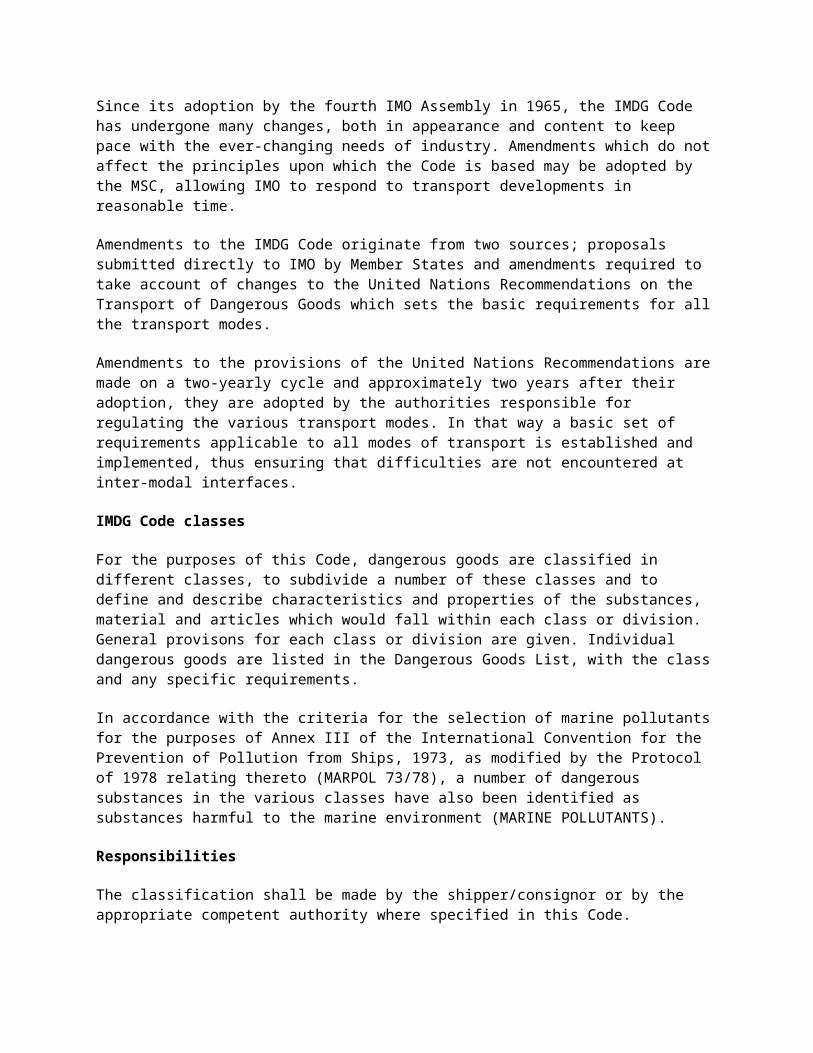
b) Functional requirementsRegulation-3:
Main vertical zone:
Sections into which the hull, superstructure and deckhouses are divided by A-class divisions.Mean length and width of which on any deck does not in general exceed 40m.
Regulation-10:
International shore connection:
Required for ships 500GT and upwards -At least one.Specifications as per FSS code.Can be used on either side of the ship.
Fire pumps:
Ships shall be provided with independently driven fire pimps.Passenger ships:
4000GT and upwards: at least three.Others: at least two.
Cargo ships:1000Gt and upwards: At least two.Others: At least two (one independent).
An emergency fire pump for cargo ships and passenger ships less than 1000GT, if fire in any compartment cause all the pumps inoperative.
Fire hoses and nozzles:
Non perishable material.At least 10m length.Not more than 15m in machinery space.Not more than 20m in other spaces and open decks.Not more than 25m for open decks for ships with max breadth more than 30m.Complete interchangeability of hose, couplings and nozzles, unless one hose and nozzle for each hydrant is provided.For cargo ships 1000GT and upwards, 1 for every 30m and 1 spare (not less than 5).This no. does not include E/R or boiler room.Nozzle size: 12mm, 16mm and 19mm or as near as thereto.Dual purpose type (jet and spray).
Portable fire extinguishers:
Comply with FSS code.Of appropriate type and sufficient number.

For ships of 1000GT and upwards: carry at least 5 extinguishers.Near entrance of an space.Carbon di oxide shall not be placed in accommodation spaces.Non-conductive extinguishing medium for control spaces and electrical spaces.Ready for use and placed at easily visible places.Spare charges: 100% for first 10 and 50% of remainder.Additional fire extinguishers, which cannot be recharged.
Fire fighter's outfit:
Comply with FSS code.Ships to carry at least two.Passenger ships: additional 1 for every 80m and part thereof, of the aggregate of all passenger spaces and service spaces.If carrying more than 36 passengers, 2 additional outfit for each main vertical zone.Tankers: two additional.Two spare charges for each breathing apparatus.
Regulation-15:
The crews shall have necessary knowledge and skills to handle fire.Crew members shall receive instructions regarding fire safety, duties.Parties for fire fighting to be organized.Crew members shall be trained regarding fire fighting.Their performance to be evaluated.
Training manuals:
Training manuals to be provided in each crew mess room and recreation room or in each crew's cabin.To be written in working language of the ship.Will contain instructions easily understood and illustrated wherever possible.
Training manuals should explain followings in details:General fire safety practice and precautions.General instructions on fire fighting activities and procedures including procedures of notification.Meanings of the ship's alarms.Operation and use of fire fighting systems and appliances.Operation and use of fire doors.Operation and use of fire smoke dampers.Escape systems and appliances.
Fire control plans:
General arrangement plans shall be permanently exhibited for the guidance of ship's officers.GA plans will show for each deck:The control stationsVarious fire sections enclosed by A and B class divisionsParticulars of fire detection and fire alarm systems.Sprinkler installationsFire extinguishing appliances.
Means of accessDecksVentilating systems including fan control positions.Position of dampersThe details may be may be set out in a booklet, if approved by director.A copy shall be supplied to each officer.One copy shall be available onboard in accessible position.Plans and booklets to be kept updated.Alterations to be recorded as soon as possible.Descriptions in these booklets to be in language(s) required by the authority.Duplicate set of fire control plans shall be permanently stored in a prominently marked weathertight enclosure outside the deckhouse for shore side fire fighting personnel.
Regulation-19:
Carriage of dangerous goods
Additional requirement for construction and equipment for safe carriage of dangerous goods regarding:
Water supplies.Source of ignition.Detection system.Ventilation.Bilge pumping.Personnel protection.Portable fire extinguishers.Insulation of machinery space boundaries.Water spray system.Separation of ro-ro spaces.
Document of compliance
An appropriate document issued by the director on an authorized organization.Evidence of compliance of construction and equipment with the requirements of this regulation.Shall be carried onboard.
HEAVY LIFT:
Required informationI will try to collect information about the heavy lift, such as:What type of cargo.The weight of cargo.Dimensions and size of the cargo.Cargo will be loaded by ship/shore's lifting gear.When the cargo is arriving.Destination of cargo.Where the cargo will be loaded as per shipper's instruction.Include the heavy lift in cargo plan, considering all the aspects of cargo planning..Rigging of heavy liftAll gears associated with lifting such as runners, guy pendants, tackles, blocks etc, to be examined
carefully.Lifting gears and associated equipments to be greased and renewed as necessary.All other riggings cleared.Rig wires, blocks etc as per rigging plan.Rig Preventers and backstays as per the plan.Topping lift in good condition and securely shackled (moused).Winches should be in double gear.Derrick unclamped from mast.Set tight preventer guys.Rig extra stays if requiredOnce clamp removed, take weight on messenger and slowly lower the derrick.
Prior lifting
Check vessel’s stability.Maximum possible loss of GM in the operation to be calculated.Maximum possible list and trim during operation to be calculated.Free surface effects to be considered.All tanks should be pressed up or empty to avoid free surface effect.Vessel to be even keel and upright as far as practicable.Rig fenders.Cast off any barge.Test the SWL of the lifting gear and associated equipments, it must be below the weight to be lifted.Check load density of the hatch/deck area the load being loaded.Load density must not exceed the value given in stability booklet.Distribute load on deck using dunnage.Rails removed.Barges cast off.Unnecessary personnel removed.Lashing arrangement is sufficient. Extra lashing points may be welded.
When lifting
Inform E/Room and galley.Inform all relevant personnel.Ensure fore and aft moorings are taut and tended.Use steadying lines (swing preventers).Competent winchman.Communication signals understood. Standard signals as per COSWP to be used.Only one competent person to signal the whole operation.Whole operation to be supervised by a responsible officer.Raise gangway.The derrick to be plumbed over the weight.Take weight slowly.Lift the load slowly, swing in the correct position and load on the appropriate position.Control swing by steadying stays.Consider emergency action if vessel develops heavy list (more than calculated) during the operation.Take proper lashing, considering heavy weather on the voyage.
Best place to loadBest place is where extra strengthening is provided by:

Longitudinals, plate floors.Solid floors or transeverses.Examples: along longitudinal center girder, lower hold abaft machinery space.Load density not to be exceeded.In the hatch, in preference to on deck because of larger GM.
MSL:
Maximum Securing Load (MSL) is a term used to define the allowable load capacity for a device used to secure cargo to a ship. Safe Working Load (SWL) may be substituted for MSL for securing purposes, provided this is equal to or exceeds the strength defined by MSL.The MSLs for different securing devices are given in table 1.The MSL of timber should be taken as 0.3 kN/cm2 normal to the grain.Following table shows determination of MSL from breaking strength
Material MSLshackles, rings, deckeyes, turnbuckles of mild steel
50% of breaking strength
fibre rope33% of breaking strength
web lashing50% of breaking strength
wire rope (single use)80% of breaking strength
wire rope (re-useable)30% of breaking strength
steel band (single use)70% of breaking strength
chains50% of breaking strength
For particular securing devices (e.g. fibre straps with tensioners or special equipment for securing containers), a permissible working load may be prescribed and marked by authority. This should be taken as the MSL.When the components of a lashing device are connected in series (for example, a wire to a shackle to a deckeye), the minimum MSL in the series shall apply to that device.
Documents require to carry dangerous goods
Document of compliance (SOLAS CH-2/II, regulation-19, Paragraph-4).DG Note/ Shipper's declaration of DG goods which will include: (SOLAS CH-VII, Regulation-4).Proper shipping nameUN noClass and divisionPackaging groupNo and kind of packagesQuantityDate of preparation of declarationName, rank, company and address of signatory.

DG manifest (SOLAS CH-VII, Regulation-4).Detailed stowage plan.(SOLAS CH-VII, Regulation-4).
Source: CSS code, Annex-13, sec-4.
Preparations and precautions for loading grain
Prior loading:
Make a pre stowage plan.Get cargo information from the shipper.Calculate the stability criteria complies with the requirement of International grain code.Planning, calculation and loading to be made for ship's stability at all stages of loading.Clean and prepare cargo holds for loading grain.Clean and test cargo hold bilges.Check weather tightness of hatches.Check cargo handling gears in good operational condition.Initial draft survey to be carried out before loading grain.
During loading:
Load grain as per cargo stowage plan.Follow loading sequences.Check stresses on hull are within the limit.Trimming of cargo to be carried out as per loading plan.Precautions to be taken for grain dust to protect human hygiene and equipments.Check cargo for any sort of damage.Check cargo for infestation.Check moorings at frequent intervals.
Prior sailing:
Securing cargo as per grain code, to reduce grain heeling moment.Fumigate the cargo using pesticides if required.All cargo holds to be closed and properly secured.Prevent entering of sea water during adverse weather condition.Take proper draft and calculate loaded quantity by final draft survey.Calculate final state of stability after completion of loading.
During the voyage:
Check humidity and adjust ventilation if required.Regular sounding of bilges.Ensure ship's stability is maintained.Inspect securing arrangements regularly if possible.
Document of authorization

A document of authorization shall be issued for every ship loaded in accordance with the regulations of this Code either by the Administration or an organization recognized by it or by a Contracting Government on behalf of the Administration. It shall be accepted as evidence that the ship is capable of complying with the requirements of these regulations.The document shall accompany or be incorporated into the grain loading manual provided to enable the master to meet the requirements of A 7 (Stability requirement). The manual shall meet the requirements of A 6.3 (Information regarding ship stability and grain loading).Such a document, grain loading stability data and associated plans may be drawn up in the official language or languages of the issuing country. If the language used is neither English nor French, the text shall include a translation into one of these languages.A copy of such a document, grain loading stability data and associated plans shall be placed on board in order that the master, if so required, shall produce them for the inspection of the Contracting Government of the country of the port of loading.A ship without such a document of authorization shall not load grain until the master demonstrates to the satisfaction of the Administration, or of the Contracting Government of the port of loading acting on behalf of the Administration, that, in its loaded condition for the intended voyage, the ship complies with the requirements of this Code. See also A 8.3 (Stability requirements for existing ships) and A 9 (Loading grain without DOA).
SOURCE: IMO Grain CodePart-A, Sec-3.
LOADING Grain without DOA
9.1. A ship not having on board a document of authorization issued in accordance with A 3 of this Code may be permitted to load bulk grain provided that:
1. the total weight of the bulk grain shall not exceed one third of the deadweight of the ship;
2. all filled compartments, trimmed, shall be fitted with centreline divisions extending, for the full length of such compartments, downwards from the underside of the deck or hatch covers to a distance below the deck line of at least one eighth of the maximum breadth of the compartment or 2.4 m, whichever is the greater, except that saucers constructed in accordance with A 14 may be accepted in lieu of a centreline division in and beneath a hatchway except in the case of linseed and other seeds having similar properties;
3. all hatches to filled compartments, trimmed, shall be closed and covers secured in place;
4. all free grain surfaces in partly filled cargo space shall be trimmed level and secured in accordance with A 16, A 17 or A 18;
5. throughout the voyage the metacentric height after correction for the free surface effects of liquids in tanks shall be 0.3 m or that given by the following formula, whichever is the greater:
Fog develops for a variety of reasons and a number of types can he identified:
1. Advection fog 2. Sea Smoke3. Radiation fog4. Frontal fog

Advection Fog
Advection fog develops as a result of a mass of warm air, with a high relative humidity value, moving horizontally (hence the term adveciion) over a cooler surface, whose temperature is below the dew-point temperature of the air.As a result of conduction aided by turbulence, the air is cooled below its dew-point temperature. water vapor condenses, the water droplets producing the mist/fog condition.This type of fog forms and persists under a wide range of wind speeds. The degree of turbulence dictates the maximum height to which the air is cooled, the height increasing with increasing wind speed.At sea advection often termed sea fog, occurs at certain times of the year. In northern latitudes, the Grand Banks of Newfoundland and the North Pacific zones are notorious particularly in July, when warm air from the south-west and south pass over the cold waters of the Labrador, and the Oyo Shio or Aleutian Currents respectively. Sea fog also occurs in lower latitudes during the summer in the region of the cold California, Canary, Peru and Benguela Currents.Sea fog not only develops where cold currents exist. but also where there are favorable conditions of wind speed, air and sea surface temperatures. Examples are the spring and early summer fogs of the Western Approaches to the British Isles, where the south-westerly warm air stream from the Azores moves over the sea which. at this time of the year, is at its lowest temperature.In the North Sea. sea fog develops during the summer when warm north-east, east and sometimes south-easterly winds from Europe pass over the colder sea surface. Along the east coast of the British Isles this sea fog is called haar or sea fret.On land, warm air moving over cold surfaces may also produce advection fog. In the British Isles this usually occurs in winter through advection of a warm air stream from the Azores. At this time of year advection fog also develops over the southern and eastern areas of the United States of America, when warm air is advected from the Gulf of Mexico and the Bermuda region.Sea fog is a frequent threat to the seafarer and its prediction is therefore important. As sea and dew-point temperatures are critical in its formation, their observation at frequent intervals is recommended, and should he recorded in graphical form. By drawing straight lines to establish the trend of each temperature. it is possible to determine the point of intersection, which indicates when fog may he encountered.
Sea Smoke
Sea smoke, arctic sea smoke, frost smoke, or steam fog is present when the surface of the sea has a steaming or smoky appearance.This fog is often patchy and extends to a limited height above the surface, with good visibility at bridge level but poor from the upper deck.The condition is caused by the movement of cold air over a warmer surface, the temperature difference usually being of the order of 10°C, although given favorable wind conditions it may occur with smaller differences.The air immediately above the surface is heated and becomes saturated through evaporation from the surface.It ascends and mixes with colder unsaturated air above.Since the mixture is supersaturated, condensation occurs and the water droplets form sea smoke.The wind speed associated with the formation of sea smoke may vary from very low to gale force.Higher speeds are more favorable when the temperature difference is small, as they ensure a continuous supply of cold air immediately above the surface.Off the cast coasts of the North American and Asian continents sea smoke occurs during the winter months, when cold air from the continent passes over estuaries, coastal waters, and adjacent ocean areas.During winter it occurs in the Baltic Sea which is surrounded by a colder land mass, and in higher
latitudes it is associated with cold winds from the Arctic Basin and the ice covered sea areas to the south.In lower latitudes it occurs occasionally in the Gulf of Mexico and off Hong Kong.
Radiation Fog
Radiation fog is a land based fog in its development.Clear skies. a high relative humidity, very low wind speeds and a relatively long period during which the air can cool are the most suitable conditions for its formation.The clear sky condition allows the maximum loss of long wave radiation from the surface during the night.Surface temperatures decrease rapidly and the air immediately above is cooled through conduction aided by turbulence.Once the air is cooled below its dew-point temperature, condensation occurs and radiation fog is produced.Since the length of the cooling period is critical, radiation fog is more common during the autumn and winter in mid and high latitudes e.g. in the British isles.Radiation fog will affect visibility at sea if it drifts over estuaries and coastal waters as a result of light offshore winds.Radiation fog may disperse as a result of an increase in land surface temperature during the day, since the surface heats the air immediately above, and lowers its relative humidity.An increase in wind speed can also cause dispersal since it overturns the air.In tropical regions, radiation fog is comparatively rare at sea level, but may be experienced over river estuaries during the early hours of the morning.The fog develops during the night over adjacent river banks, where the air has a high relative humidity due to the presence of open water.
Ship security system
Security level: There are 3 security levels, namely, Security Level 1, Security Level 2, and Security Level 3, defined in the ISPS Code.Flag States will set security level for their ships.A ship prior to entering a port or while in the port, is required to comply with the security level of the flag state or the port state, whichever is the higher.The master is required to have information on board concerning persons or organizations responsible for the appointment and employment of crew members of the ship.Ships are to be provided with a ship security alert system.Ships are subjected to port state control with respect to compliance with chapter XI-2. The port state control inspection in this respect is limited to verifying that there is on board a valid international ship security certificate (ISS certificate) issued under the provisions of Part A of the ISPS Code.The master of a ship has the overriding authority and the responsibility to make decisions and measures with respect to the safety and security of the ship.A ship is required to carry on board a ship security plan approved by the flag state on the basis of a ship security assessment.The company operating a ship shall designate a company security officer (CSO) for the ship.Each ship is required to have a designated ship security officer (SSO).The CSO, the SSO, appropriate shore-based personnel and shipboard personnel having specific security duties and responsibilities are required to undergo training in maritime security in accordance with the guidance given in Part B of the ISPS Code.Drills and exercises with respect to the ship security plan are required to be carried out at appropriate intervals by all parties concerned with the ship security plan.A ship, after a verification that the ship complies with chapter XI-2 and the ISPS Code will be issued an

International ship security certificate (ISS Certificate) valid for a period not exceeding 5 years. Within the 5-year validity period of the ISS Certificate, the ship is required to have an intermediate verification which will be endorsed on the ISS certificate.A ship is required to act upon the security levels set by the port state or the flag state, whichever is appropriate by carrying out the activities prescribed in the ISPS Code with the aim of identifying and taking preventive measures against security incidents. Painting Scheme:
The painting on board a ship is divided into three regions
-Below the water line: where the plates are continuously immerged into water.-Boot top area where the immersion is intermittent and much abrasion occurs.The top side & superstructure.
Take over a vessel as a chief officer
Report to master, hand over appointment letter/ introductory letter, CoC and other certificates, sign article of agreement.Meet the outgoing C/O.Go through handing over note.Initial familiarization:
Emergency stations and duties.Ship’s dimension, lay out, particulars.LSA and FFA plansNormal loading and discharging procedures.Stability booklet and hydrostatic data.Damage Stability booklet.Oil record books, entries.Garbage record books, entries.Loadicator
How to input dataHow to get resultWhere is the back-up discComputer being used is approvedAny password for operating/installing the programPiping diagram: ballast, FW, bilges.Capacity plansLashing plansCargo securing manualsStowage planBridge equipment, navigation equipments, emergency steering procedures.Deck maintenance
Planned maintenance scheduleCurrent state of maintenanceStatus of deck stores, equipments. Take inventories of various deck stores, lashing gears.Any requisition made or to be made.

Go through mate’s log book.Surveys and certificates
Status of various statutory certificates, expiry, validity.Any survey due, perpetrations required.Chain register, entries in chain register.Certificates for lifting gears, attached equipments, wires and ropes etc.Operational manuals.Lifting and mooring equipments
Condition of lifting machineries and mooring equipments.Any outstanding repairs.Ports, voyages
Peculiarity of ports, stevedores working hours, interaction with shore personnel, lifting of stores, water, bunker, provisions.Port regulation, restrictions, cargo documents required, draft restrictions, day-night berthing/unberthings.Shore leave, gangway, watchman.Pilferage by shore gang.Deck watch, anchor watch, piracy watch arrangements.Staff matters
Morale of crews, ability and weakness.Work rotation, overtime system.Officer-crew relationship.Efficiency and performance of other duty officers regarding cargo operation.Others
Jobs regarding to training and assessmentsISM files to maintainISM documents to send to company, their frequencies.Condition of deck, hatches, hatch covers, lifting machineries.Hold ventilation systemsAnti-pollution and bunkering proceduresEmergency proceduresReport any discrepancy to masterSign take over documentIn dry dock
Docking plan.Dry dock repair list.Repair works to be done onboard and by dry dock personnel.Surveys to be done on dry dock.Safety regulations, hot works, chemical washings, men entry to enclosed spaces.Emergency contacts/ actions.Power and water supply, telephones.Take over drain plugs.Sewage and garbage disposal arrangements.Status of LSA, FFA, anything sent ashore.Instructions to duty officers and crews.

Undocking stability calculations, tank conditions.Closing-opening arrangements of hatches.Special types of ships
Container ships
Bay plansStowage of containersStowage of IMDG containers, cargoes.Stowage of refer containersContainer lashing gearsNormal stacking heightBulk carriers
Ballasting-deballasting ratesGrain loading bookletHigh density cargo loading proceduresLoad density of deck, tank tops.Capacities of load/discharge top side tanks.Refrigerated ships
Check condition of compressorsCheck any deficiencies in maintaining temperaturesInsulations of compartments in good condition.Brine seals of tween deck.Conditions of gratings and dunnages.Ro-ro ships
Power operated W/T doors working properlyFFA in all decks in good conditionElectrical wiring maintainedCargo securing arrangementsBow door closing/opening arrangements and alarmsLighting arrangementsTankers
Operation of cargo pumps, eductorsCargo piping systemBallast piping and pumping systemIG system and linesGas detection system, operation, calibration.Cargo tank washing proceduresProcedures for loading different gradesCrude oil washing system (crude carriers)For chemical tankers
Cargo compatibility and segregationSpecial precautions required for certain cargoes.Cargo tank washing proceduresPrevious cargoes

For gas carriers
Vapor lines, reliquefaction linesReliquefaction plantsCargo change over proceduresCargo conditioning proceduresCargo loading and discharging procedures in various portsLNG ships
Type of tanks.Controlling boil off.Tank insulation.Inerting procedures of primary and secondary barriers.
ISPS:
The ISPS Code is a set of measures to enhance the security of ships and port facilities. It was developed in response of the perceived threats to ships and port facilities after the 9/11 attacks. The ISPS Code is part of the Safety of Life at Sea Convention (SOLAS) and compliance is mandatory for the 148 Contracting Parties to SOLAS.The ISPS Code was adopted by one of the resolutions that was adopted on 12 December 2002 by the Conference of Contracting Governments to the SOLAS, 1974 (London, 9 to 13 December 2002). Another resolution includes the necessary amendments to chapters V and XI of SOLAS that mandates compliance with the Code on 1 July 2004. The existing chapter XI of SOLAS was amended and re-identified as chapter XI-1. A new chapter XI-2 was implemented based on special measures to enhance maritime security. Part A of the ISPS Code contains the mandatory requirements regarding the amended provisions of chapter XI-2 of SOLAS , 1974; Part B provides guidance regarding these amended provisions. You may purchase copies of the ISPS Code and the amendments to SOLAS from binnacle.com.
Upper Deck :
The upper deck is the uppermost complete deck exposed to weather and sea, which has permanent means of weathertight closing of all openings in the weather part thereof, and below which all openings in the sides of the ship are fitted with permanent means of watertight closing. In a ship having a stepped upper deck, the lowest line of the exposed deck and the continuation of that line parallel to the upper part of the deck is taken as the upper deck.
Moulded Depth:
(a) The moulded depth is the vertical distance measured from the top of the keel to the underside of the upper deck at side. In wood and composite ships the distance is measured from the lower edge of the keel rabbet. Where the form at the lower part of the midship section is of a hollow character, or where thick garboards are fitted, the distance is measured from the point where the line of the flat of the bottom continued inwards cuts the side of the keel.
(b) In ships having rounded gunwales, the moulded depth shall be measured to the point of intersection of the moulded lines of the deck and side shell plating, the lines extending as though the gunwales were of angular design.
(c) Where the upper deck is stepped and the raised part of the deck extends over the point at which the moulded depth is to be determined, the moulded depth shall be measured to a line of reference extending from the lower part of the deck along a line parallel with the raised part.
Breadth:
The breadth is the maximum breadth of the ship, measured amidships to the moulded line of the frame in a ship with a metal shell and to the outer surface of the hull in a ship with a shell of any other material.
Enclosed spaces:
Enclosed spaces are all those spaces which are bounded by the ship's hull, by fixed or portable partitions or bulkheads, by decks or coverings other than permanent or movable awnings. No break in a deck, nor any opening in the ship's hull, in a deck or in a covering of a space, or in the partitions or bulkheads of a space, nor the absence of a partition or bulkhead, shall preclude a space from being included in the enclosed space.
is completely open except for bulwarks or open rails separates any two spaces, the exclusion of one or both of which is permitted under sub-paragraphs (a)(i) and/or (a)(ii), such exclusion shall not apply if the separation between the two spaces is less than the least half breadth of the deck in way of the
Cargo Spaces:
Cargo spaces to be included in the computation of net tonnage are enclosed spaces appropriated for the transport of cargo which is to be discharged from the ship, provided that such spaces have been included in the computation of gross tonnage. Such cargo spaces shall be certified by permanent marking with the letters CC (cargo compartment) to be so positioned that they are readily visible and not to be less than 100 millimetres (4 inches) in height.
Weathertight:
Weathertight means that in any sea conditions water will not penetrate into the ship.
TANK SURVEY WITH WATER BOAT:
For overall survey, means should be provided to enable the surveyor to examine the structure in a safe and practical way. For close-up surveys, one or more of the following means for access, acceptable to the surveyor, should be provided:
.1 Permanent staging and passages through structures;
.2 Temporary staging and passages through structures;
.3 Lifts and moveable platforms;
.4 Boats or rafts;
.5 Portable ladders;
.6 Other equivalent means.
Surveys of tanks by means of boats or rafts may only be undertaken with the agreement of the surveyor, who should take into account the safety arrangements provided, including weather forecasting and ship response in reasonable sea conditions.
When rafts or boats will be used for close-up survey the following conditions should be observed:
1 Only rough duty, inflatable rafts or boats, having satisfactory residual buoyancy and stability even if one chamber is ruptured, should be used;2 The boat or raft should be tethered to the access ladder and an additional person should be stationed down the access ladder with a clear view of the boat or raft;3 Appropriate lifejackets should be available for all participants;4 The surface of water in the tank should be calm (under all foreseeable conditions the expected rise of water within the tank should not exceed 0.25 m) and the water level either stationary or falling. On no account should the level of the water be rising while the boat or raft is in use;5 The tank or space must contain clean ballast water only. Even a thin sheen of oil on the water is not acceptable;6 At no time should the water level be allowed to be within 1 m of the deepest under deck web face flat so that the survey team is not isolated from a direct escape route to the tank hatch. Filling to levels above the deck transverses should only be contemplated if a deck access manhole is fitted and open in the bay being examined, so that an escape route for the survey party is available at all times. Other effective means of escape to the deck may be considered;7 If the tanks (or spaces) are connected by a common venting system, or Inert Gas system, the tank in which the boat or raft should be used should be isolated to prevent a transfer of gas from other tanks (or spaces).Rafts or boats alone may be allowed for inspection of the under deck areas for tanks or spaces if the depth of the webs is 1.5 m or less.
If the depth of the webs is more than 1.5 m, rafts or boats alone may be allowed only:1 When the coating of the under deck structure is in GOOD condition and there is no evidence of wastage; or2 If a permanent means of access is provided in each bay to allow safe entry and exit. This means of access should be direct from the deck via a vertical ladder with a small platform fitted approximately 2 m below the deck. Other effective means of escape to the deck may be considered.If neither of the above conditions are met, then staging or other equivalent means should be provided for the survey of the under deck areas. The use of rafts or boats alone in 5.5 and 5.6 does not preclude the use of boats or rafts to move about within a tank during a survey.
5.3. Fire mains:
Pressure requirements for fire mainsThe fire-fighting system is also a central element of the SOLAS Convention, so it contains many requirements.Chapter II-2, Regulation 4 of the SOLAS Convention, "Fire pumps, fire mains, hydrants and hoses" contains the details of the regulations governing this aspect.

The maximum pressure calculation must be done with standard nozzle sizes. The fire hose nozzle specifications are set out in point 8: Nozzles. It states that for machinery spaces and exposed locations, the nozzle size shall be such as to obtain the maximum discharge possible from two jets at the pressure mentioned in paragraph 4 from the smallest pump, provided that a nozzle size greater than 19 mm need not be used.All nozzles shall be of an approved dual-purpose type (i.e., spray/jet type) incorporating a shutoff.The maximum pressure is the pressure that the system can support. This means that it shall not exceed that at which the effective control of a fire hose can be demonstrated.
The minimum pressure required varies based on the type of ship (passenger ship or cargo ship) and its tonnage according to the table below:
Passenger Ships of 4,000 gross tonnage and upwards - 320 kPa1,000 gross tonnage and upwards but under 4,000 gross tonnage - 270 kPaUnder 1,000 gross tonnage - To the satisfaction of the AdministrationCargo Ships6,000 gross tonnage and upwards - 270 kPa1,000 gross tonnage and upwards but under 6,000 gross tonnage - 250 kPaUnder 1,000 gross tonnage - To the satisfaction of the Administration
Determination of weight onboard shipTwo methods of determining the weight of a dry bulk cargo loaded onboard a ship have in the past been used:■ On the basis of the ‘free space’ in a compartment (measurement and stowage factor).■ On the basis of draught surveys.
GRAIN LOADING AND STABILITY: The shift of cargo, and thus proper stowing, is a concern for ships carrying dry cargo. Cargo that is accidentally shifted can result in a lack of stability and, in the worst case, the total loss of a ship.
Cargo may shift either as a result of poor stowing combined with bad weather or as a secondary effect of an accident that causes the vessel to heel, such as a collision, grounding or system malfunction.

Shift of grain cargo Grain is a type of cargo that can easily shift when the ship is rolling. The grain may in such conditions suddenly form a new surface with an angle of as much as 25 degrees to the original horizontal loaded surface. This will create a heeling moment that in turn reduces the ship's stability. If the ship is subject to a steady heel over time, this may escalate the situation, in that more grain may be shifted.
The grain surface may be physically secured by cloths weighed down by bags on top or by other means (Ref. The IMO's Grain code, A 16 to A 18). However, this is time-consuming and most ships engaged in the grain trade operate without physically securing the load in order to reduce the time spent in port.
Check language of this sentence: In an "unsecured" grain load, the grain may shift in the available void spaces formed between the loaded grain surface and the deck and hatch. The larger the voids, the larger the potential grain heeling moment will be. There is a significantly higher potential grain heeling moment in a partly filled hold than in a hold that is fully loaded. The void space under the deck also depends on the "trimming" (levelling) of the grain surface. The more grain that is filled (trimmed) up in the "under deck" part of the hold, the less void space will be left.
The trimming of under deck parts ("ends") in a full hold may also be a time-consuming and labour-intensive job. If the "ends" are not trimmed (so-called "untrimmed ends"), the grain surface will form a natural slope from the lower part of the hatch opening (or from special feeding holes) towards the ends of the hold. This produces a void space above this sloping surface, and hence there may be a larger heeling moment than in a "trimmed" hold.
Grain stability requirements and the Grain Loading Declaration To prevent accidents related to a loss of stability due to a shift of grain, grain stability requirements were gradually developed by the IMO from the earliest mention of this at the SOLAS conference in 1948 until the "International Grain Code" (MSC.23(59)) was adopted on 23 May 1991.
The grain code contains specifications regarding grain stowage, a description of grain heeling moment calculations, stability requirements and documentation requirements. For grain stability, there are requirements regarding the residual stability (area under GZ curve), minimum GM and maximum heel of 12 degrees due to grain shift.
In order for a ship to be allowed to carry grain without physically securing the grain surface, it should be equipped with an approved grain loading manual containing, among other things, information on:
allowable grain heeling moments the grain heeling moments for filled holds and trimmed and untrimmed ends (if
applicable) the grain heeling moment for partly filled holds instructions for grain calculations typical grain loading conditions
This should assist the crew in selecting loading conditions that will be safe for sailing.
The grain code also requires the ship to carry a "Grain Loading Declaration" issued by the administration, documenting that grain may be carried safely and with a reference to the approved grain loading manual.
DNV is authorised to approve grain stability documentation and issue grain loading declarations for most flag states worldwide.
Grain includes one of the following:- (1) Wheat (2) Maize (3) Oats (4) Rye (5) Barley(6) Rice (7) Pulses (8) Seeds(Any of the above can cause self combustion due to the gases given off)(Q) How can you find out if you can carry 20,000 tonnes of grain on his vessel?(a) You need to refer to the vessel's stability book to see what the vessel can carry in each holdAlso check out the following(1) Check out the grain loading plans(2) Check out the stowage details for the grain (Stowage factor which you get from the shipper)Find out the ships volume for that compartment which is in the ships cargo plan, then you get the stowage factor from the shipper, the person who own's the grain(3) Find out what type of grain your taking onboard and see if it gives off dangerous gases(4) Find out the freeboard/draught before loading and after loading(5) make sure the grain cannot shift by using boards transversely and athwart-ships to minimize F.S.E.(6) Check for overheating (Sweating by cargo sweat or ships sweat) Both are very dangerous (both can self-ignite)
Cargo Sweat and what is ships sweat(a) Cargo Sweat is where the air in the hold is hotter that the air outside the holdShips sweat is where the air outside the hold is hotter that the air inside the hold(Q) What check's would you take before loading "Grain"?(a) Make sure that the vessel is totally empty and fumigated (it can be oxygen deficient or have flammable gases in it)(Q) What is the main danger when going into a hold that has not been fumigated?(a) No oxygen, the fumes inside a hold can kill, it's happened a lot of times in the past(Q) What are the Rules for entering an enclosed space?(1) Get the skippers permission(2) Ventilate the enclosed space(3) Test the oxygen count(4) Put S.C.B.A. (Self Contained Breathing Apparatus) on (if needed)(5) Use a lifeline(6) Have someone trained in first aid close by(7) Have fire-extinguishers close by(8) Use hard-hats, protective clothing, steel-toe cap boots and gloves(9) Inform the skipper when done(Q) If you have a hold that has slack tanks with the amount of grain in it, what should you do with this?

(a) Look up the SOLAS manual this will give you the angle of repose and the amount of space you need fro expansion for the grain to expand
Cargo Information(1) A description of the cargo(2) the gross weight of the cargo(3) The Dimensions of the cargo(4) Any special properties of the cargo
For Bulk Cargoes(1) The stowage factor of the cargo(2) The trimming procedures(3) For concentrate or other cargo which may liquefy, additional information in the form of a certificate indicating the moisture content of the cargo and its transportable moisture limit;Bulk cargoes which are not classified in accordance with Regulation VII/2 of the SOLAS Convention, but have chemical properties that may create a potential hazard. Information on the chemical properties besides the information for bulk cargoes aboveAll information must be given to the master prior to loading any cargo on proper shipping documentation (the master must check that this documentation is correct before taking the cargo onboard – accidents has happened because of the documentation being wrong)With containers and cargo units the shipper must check that the gross tonnage/dimensions are correct (an near accident happened with a document saying the gross tonnage of a container was 3 tonnes – with it’s contents, the master was asked to take the container aboard with the ships crane – the crane had a S.W.L. of 5 tonnes, when the crane took the initial weight of the container, the initial strain taken madethe ship list badly towards the quay, the master screamed to stop the crane which the crane operator did, later they found the gross weight of the container was 7 tonnes – a misprint – but it could have been a nasty accident)If the shipper or the agent does not supply the documentation to the master the forwarder shall supply the information well in advanceA master will not take cargo aboard without all the information he requires (this is an offence if he does).
Cargo DocumentationEvery cargo except a ship carrying grain shall have the following documentation(1) the Code of Safe Practice for Cargo Stowage and Securing adopted by the Organization by Resolution A.714(17), 1992 edition;(2) the Code of Safe Practice for Ships Carrying Timber Deck Cargoes adopted by the Organization by Resolution A.715(17), 1992 edition; and(3) the Code of Safe Practice for Solid Bulk Cargoes (BC Code) adopted by the Organization by Resolution A.434(XI), 1991 edition.Every vessel carrying grain shall have the following documentation onboard;International Grain Code, Stowage and securing.The operator and master must ensure that the following are undertaken;
(1) cargo and cargo units carried on or under deck are loaded, stowed and secured so as to prevent as far as is practicable, throughout the voyage, damage or hazard to the ship and the persons on board, and loss of cargo overboard(2) appropriate precautions are taken during loading and transport of heavy cargoes or cargoes with abnormal physical dimensions to ensure that no structural damage to the ship occurs and to maintain adequate stability throughout the voyage;(3) appropriate precautions are taken during loading and transport of cargo units on board ro-ro ships, especially with regard to the securing arrangements on board such ships and on the cargo units and with regard to the strength of the securing points and lashings.Oxygen analysis and gas detection equipmentShips carrying cargoes that emit a toxic or flammable gas or causes oxygen depletion(1) In the case of a ship transporting or accepting for transport a bulk cargo which is liable to emit a toxic or flammable gas, or cause oxygen depletion in the cargo hold, an appropriate instrument for measuring the concentration of gas or oxygen in the air shall be provided together with detailed instructions for its use. Such an instrument shall be of a type approved by a Certifying Authority, and the crew shall be trained in its use.(2) The operator of a ship which transports, or the master who accepts for carriage, such a bulk cargo without ensuring that paragraph (1) has been complied with shall be guilty of an offence.Requirements for Cargo Ships Carrying Grain and International Grain Code(1) A ship carrying grain shall comply with the requirements of the International Grain Code(2) Without prejudice to paragraph (1) or any other requirement of these Regulations, the operator and master shall ensure that:(a) a ship loading grain complies with the International Grain Code; and(b) subject to paragraph (4)(b), the ship has on board a document of authorization as required by the International Grain Code. In the case of a United Kingdom ship the document of authorization shall be issued by the Certifying Authority.(3) Except when a ship may be in distress, the operator and master shall not permit a ship loaded with grain in bulk outside the United Kingdom to enter any port in the United Kingdom so laden, unless the ship has been loaded in accordance with the International Grain Code.(4) No person shall order the commencement of the loading of grain into a ship in the United Kingdom unless he is satisfied that:(a) the ship has on board a document of authorization referred to in paragraph (2)(b); or(b) the master has demonstrated to the satisfaction of the Certifying Authority that the ship will, in its proposed loading condition, comply with the appropriate requirements of the International Grain Code and has obtained a document to this effect signed by a surveyor of such a Certifying Authority.(5) An operator or master who contravenes paragraph (2) or (3) shall be guilty of an offence.(6) A person who contravenes paragraph (4) shall be guilty of an offence.13. - (1) A person guilty of an offence under Part II, III or IV of these Regulations shall be liable on summary conviction to a fine not exceeding the statutory maximum or, on conviction on indictment, to imprisonment for a term not exceeding two years or a fine or both.(2) In any proceedings for an offence under Part II, III or IV of these Regulations it shall be a defence for a person to prove that all reasonable steps had been taken by that person to ensure compliance with the Regulations.

FUMIGATION:
Fumigation in charge to be designated by appropriate authority.FIC will provide master the following information:
Type of fumigantHazardsTLVPrecautions to observe.
Fumigation in port
In port, normally fumigation is done in empty cargo spaces and accommodations.It is done by certified fumigator companies.
Preparations
A thorough cleaning of cargo spaces after discharge.Box beams, stiffeners, deck girders, pipe casings, bilge wells, strum boxes etc, are cleaned thoroughly from cargo residues.Cargo spaces to be air tight.All compartments, accommodations, store rooms to be available to the fumigators.They should be opened internally, but outside doors locked.Food staffs must be removed unless permitted by fumigators.The ship has been prepared as required by the fumigator.Watchmen posted to prevent unauthorized boarding.Warning notices posted on gangway and entrances of the accommodation.All crews to be landed ashore during the fumigation period.A complete search to be carried out for any crew or person left onboard and a certificate is given by master, countersigned by fumigator to this respect.All blowers, air cons, fans in holds and accommodations to be switched off. The generators may be shut off for the fumigation period.
Procedures
Fumigation is carried out to disinfest the ship.Carried out in cargo holds and accommodations.Strong toxicants are used.Fumigants are applied as solid or liquid but act as gases.No pesticides to be applied on human or animal foods without professional’s advice.After all preparation and precautions, fumigant is released and the ship kept under gas for at least two hours for empty ship and four hours for loaded ship.Entry to be made in fumigated spaces in an extreme emergency.People must be wearing protective equipment, breathing apparatus and safety harness in case of such an entry.
As per the fumigators, when the ship is disinfested adequately,Fumigator is to inform master.With assistance of necessary crew, they will gas free the ship.Engine personnel to start generator, ventilation fans.

The must be wearing sufficient protective clothing with breathing apparatus.When the ship is gas free and safe for reoccupy, a test of all spaces to be made for toxic gases and oxygen content.A gas free certificate is to be issued by fumigators stating that the ship is free of toxic gases and safe for re-occupancy.
Fumigation at sea
Done at the discretion of master.Master to be aware of the flag state regulations regarding transit fumigation.Done only in cargo spaces, empty or loaded.It may be done in following occasions:Fumigation done in port but ship is not gas freed.Fumigation is done but no clearance certificate is issued.
Preparation:
Fumigators to demonstrate and train required ship personnel, at least 2 crews and one officer.A trained representative should brief the crews before the operation takes place.A thorough cleaning of empty cargo spaces after discharge.Box beams, stiffeners, deck girders, pipe casings, bilge wells, strum boxes etc, are cleaned thoroughly from cargo residues.Cargo spaces to be air tight.Warning notices to be posted.Details of fumigants, their properties, hazards are known.Symptoms of poisoning are known.First aid and emergency procedures in case of poisoning are known.Required medicines are on board.A copy of latest MFAG is onboard.Necessary gas detection equipments are available.Protective equipments are available.Measures taken to ensure E/R, accommodation and other working areas are free of fumes and prevent leakage of fumigants.
Procedures
Fumigation is carried out by fumigators and/ or trained personnel.Carried out in cargo holds.Strong toxicants are used.Fumigants are applied as solid or liquid but act as gases.No pesticides to be applied on human or animal foods without professional’s advice.After all preparation and precautions, fumigant is released and the ship kept under gas for specified time required by fumigators, generally 1 week.After ascertaining that the ship is safe to sail and there is no leakage, the FIC should furnish the master following written statement:The gas in hold spaces reached certain high concentration to determine any leakage.Spaces adjacent to the cargo spaces have been checked and found gas free.The ship's representative is fully conversant with the use of gas detection equipment.Entry to be made in fumigated spaces in an extreme emergency.People must be wearing protective equipment, breathing apparatus and safety harness in case of such an

entry.When the spaces are disinfested sufficiently (after required time as per the fumigators):Thorough ventilation of cargo spaces is done.Cargo holds may be opened few days before arrival port.A test for the presence of toxic gases is made.All to be done under supervision of trained personnel.Protective equipments are to be worn.Discard of residues of fumigants as per fumigators advice.A detail entry of all the procedures in deck log and official log book is to be made in chronological order.
SOLAS Chapter XII regulationsThe regulations state that all new bulk carriers 150 metres or more in length (built after 1 July 1999) carrying cargoes with a density of 1,000 kg/m3 and above should have sufficient strength to withstand flooding of any one cargo hold, taking into account dynamic effects resulting from presence of water in the hold and taking into account recommendations adopted by IMO.
For existing ships (built before 1 July 1999) carrying bulk cargoes with a density of 1,780 kg/m3 and above, the transverse watertight bulkhead between the two foremost cargo holds and the double bottom of the foremost cargo hold should have sufficient strength to withstand flooding and the related dynamic effects in the foremost cargo hold.
Cargoes with a density of 1,780 kg/m3 and above include iron ore, pig iron, steel, bauxite and cement. Less dense cargoes, but with a density of more than 1,000 kg/m3, include grains such as wheat and rice, and timber.
Chapter XII allows surveyors to take into account restrictions on the cargo carried when considering the need for, and the extent of, strengthening of the transverse watertight bulkhead or double bottom. When restrictions on cargoes are imposed, the bulk carrier should be permanently marked with a solid triangle on its side shell.
The date of application of Chapter XII to existing bulk carriers depends on their age. Bulk carriers which are 20 years old and over on 1 July 1999 will have to comply by the date of the first intermediate or periodical survey after that date, whichever is sooner. Bulk carriers aged 15-20 years must comply by the first periodical survey after 1 July 1999, but not later than 1 July 2002. Bulk carriers less than 15 years old must comply by the date of the first periodical survey after the ship reaches 15 years of age, but not later than the date on which the ship reaches 17 years of age.
Current work on bulk carrier safetyIMO is currently reviewing whether further measures will be needed to enhance bulk carrier safety, following the publication of the United Kingdom report into the sinking of the bulk carrier Derbyshire in 1980, with the loss of all on board.
The report was presented to the Maritime Safety Committee (MSC) in May 1998 by the United Kingdom and contains further recommendations relating to the design and construction of bulk carriers. Issues under consideration by the MSC and its Sub-Committees include:
1. strength of hatch covers and coamings;2. freeboard and bow height;3. reserve buoyancy at fore end, including forecastles;4. structural means to reduce loads on hatch covers and forward structure; and5. fore deck and fore end access.
SN/Circ.207 7 January 1999 DIFFERENCES BETWEEN RCDS AND ECDISThe Maritime Safety Committee, at its seventieth session (7 to 11 December 1998), adopted amendments to the performance standards for Electronic Chart Display and Information Systems (ECDIS) to include the use of Raster Chart Display Systems (RCDS).
These amendments permit ECDIS equipment to operate in two modes: .1 the ECDIS mode when ENC data is used; and .2 the RCDS mode when ENC data is not available. However, the RCDS mode does not have the full functionality of ECDIS, and can only be used together with an appropriate portfolio of up-to-date paper charts.
The mariners' attention is therefore drawn to the following limitations of the RCDS mode:
1 unlike ECDIS where there are no chart boundaries, RCDS is a chart-based system similar to a portfolio of paper charts;2 Raster navigational chart (RNC) data, itself, will not trigger automatic alarms (e.g. anti-grounding). However, some alarms can be generated by the RCDS from user?inserted information. These can include:- clearing lines, - ship safety contour lines, - isolated dangers, - danger areas3 horizontal datums and chart projections may differ between RNCs. Mariners should understand how the chart horizontal datum relates to the datum of the position fixing system. In some instances, this may appear as a shift in position. This difference may be most noticeable at grid intersections and during route monitoring;4 chart features cannot be simplified or removed to suit a particular navigational circumstance or task at hand. This could affect the superimposition of radar/ARPA;5 without selecting different scale charts, the look-ahead capability may be somewhat limited. This may lead to some inconvenience when determining range and bearing or the identity of distant objects;6 orientation of the RCDS display to other than chart-up, may affect the readability of chart text and symbols (e.g., course-up, route-up);7 it may not be possible to interrogate RNC features to gain additional information about charted objects;8 it is not possible to display a ship's safety contour or safety depth and highlight it on the display, unless these features are manually entered during route planning;9 depending on the source of the RNC, different colours may be used to show similar chart information. There may also be differences in colours used during day and nighttime;10 an RNC should be displayed at the scale of the paper chart. Excessive zooming in or zooming out can seriously degrade RCDS capability, for example, by degrading the legibility of the chart image; and
11 mariners should be aware that in confined waters, the accuracy of chart data (i.e., paper charts, ENC or RNC data) may be less than that of the position-fixing system in use. This may be the case when using differential GNSS. ECDIS provides an indication in the ENC which allows a determination of the quality of the data.4. Member Governments are requested to bring this information to the attention of the relevant authorities and all seafarers for guidance and action, as appropriate.
The flag state:of a commercial vessel is the state under whose laws the vessel is registered or licensed. The flag state has the authority and responsibility to enforce regulations over vessels registered under its flag, including those relating to inspection, certification, and issuance of safety and pollution prevention documents. As a ship operates under the laws of its flag state, these laws are used if the ship is involved in an admiralty case.
The term "flag of convenience" describes the business practice of registering a merchant ship in a sovereign state different from that of the ship's owners, and flying that state's civil ensign on the ship. Ships are registered under flags of convenience to reduce operating costs or avoid the regulations of the owner's country. Panama is currently the world's largest flag state, with almost a quarter of the world's ocean-going tonnage registered there.
Classification society:A classification society is a non-governmental organization that establishes and maintains technical standards for the construction and operation of ships and offshore structures. The society will also validate that construction is according to these standards and carry out regular surveys in service to ensure compliance with the standards.To avoid liability, they explicitly take no responsibility for the safety, fitness for purpose, or seaworthiness of the ship.Classification societies set technical rules, confirm that designs and calculations meet these rules, survey ships and structures during the process of construction and commissioning, and periodically survey vessels to ensure that they continue to meet the rules. Classification societies are also responsible for classing oil platforms, other offshore structures, and submarines. This survey process covers diesel engines, important shipboard pumps and other vital machinery.Classification surveyors inspect ships to make sure that the ship, its components and machinery are built and maintained according to the standards required for their class.The purpose of a Classification Society is to provide classification and statutory services and assistance to the maritime industry and regulatory bodies as regards maritime safety and pollution prevention, based on the accumulation of maritime knowledge and technology.The objective of ship classification is to verify the structural strength and integrity of essential parts of the ship’s hull and its appendages, and the reliability and function of the propulsion and steering systems, power generation and those other features and auxiliary systems which have been built into the ship in order to maintain essential services on board. Classification Societies aim to achieve this objective through the development and application of their own Rules and by verifying compliance with international and/or national statutory regulations on behalf of flag Administrations.

QUESTION AND ANSWER:
As Chief Officer what maintenance are you conducting on a lifeboat? Regularly inspect the condition of the gripes and webbing straps; Regularly inspect and grease wires, lubricate snap hooks, grease rollers; Chip and paint the davits; Check condition of lifeboat hull after each launch and retrieval; Check adhesion of retro-reflective tapes, and boat markings; Check operation of davit limit switches.
Why is the lifeboat wires constructed as 6 x 37 and not 6 x 24? The running rigging of the lifeboat needs to be of a more flexible design; The Chief Marine Surveyor has determined that the standard of rotation resistance is to be not less
than 6 x 36 steel wire rope, and the standard of corrosion resistance is to be not less than that of galvanised steel wire rope, properly lubricated and greased.
What do you understand by SOPEP, and explain what it contains? The Shipboard Oil Pollution Emergency Plan, containing procedures to be followed in case of an oil
spill; Personnel to be contacted; Authorities to contact; Mentions all the equipment the ship carries to combat and contain an oil spill.
What are the markings on a lifeboat? The number of persons the boat is permitted to carry; The name and port of registry of the ship; Means of identifying their stowage by numbering conventionally even to port and odd to starboard
and the side they belong; Retro-reflective tape of approved type, not less than 300mm long and 50mm wide:1. On the top of the gunwale; and on the outsides of the lifeboat as near to the gunwale as possible.
Spaced so that the distance between the centre of one tape and the next does not exceed 500mm; and2. Placed in such a way that 2 tapes form a cross; and spaced so that the distance between the centre of
one cross and the centre of the next cross in line does not exceed 500mm.
What is marked on the containers for liferafts? Makers name or trade mark; Serial number; Name of Approving Authority; Number of persons it is permitted to carry; SOLAS; Type of emergency pack enclosed; Date when last serviced; Length of painter; Maximum height it can be stowed above the waterline; Whether an EPIRB is fitted; Launching instructions.

Your engine room is on fire and the Master advises you that he is going to use the CO2 smothering installation. What action do you take prior to discharging the CO2? Evacuate all personnel from the machinery space to the muster station, take head count ensure all
personnel are accounted for; Ensure the E/R is completely sealed off with all openings, dampers, and flaps closed, and check that
ventilation has been shut down; Close all remote fuel stops; Open the door to CO2 control box, this will activate the CO2 audio-visual alarm system in the
machinery spaces, this will also trip any remaining ventilation fans that may be running to the E/R; Second confirmation head count; Set off CO2 on Masters orders; Continue with boundary cooling and monitoring of the system after setting off the CO2.
What are the ‘DOC’ and the ‘SMC’? The ‘DOC’ is the certificate awarded to the company after a successful audit of the company office
management on the aspects of safety management; The original DOC is held in the office and a certified copy is to be carried onboard, the certificate is
valid for 5 years with an annual audit; The ‘SMC’ is the certificate issued to the ship after the company has received the DOC and the ship
has been successfully audited, the certificate is valid for 5 years and an audit held between 2 and 3 years.
Explain in your own words, what you understand about the ISM Code? It is an international standard for the safe management and operation of ships by setting rules
for the organization of company management in relation to safety of life, property and the prevention of pollution;
The Safety Management System should ensure compliance with the mandatory rules and regulations, and the observance of applicable codes, guidelines, and recommended standards;
The SMS is to incorporate the following:1. A Safety and Environment Policy;2. The Company Responsibilities and Authority;3. Assign a Designated Person to be the contact between the ship and shore with a direct uninterrupted
link to the highest level of management in the company;4. Lay out the Master’s Responsibility and Authority;5. Develop plans for shipboard operations;6. Emergency preparedness;7. A Reporting system for Reports and analysis of any non-conformances, accidents and hazardous
occurrences;8. A Planned Maintenance System for all equipment and hull;9. A system for documentation verification, review and evaluation.
What would you suggest as an appropriate whistle signal for a vessel aground, in addition to her normal fog signal? ‘U’ – You are running into danger (. . -); or ‘L’ – You should stop your vessel immediately (. - . .);
What is the minimum recommended safe passing distance off an oil rig?

All rigs have a 500m safety zone around them, so the minimum distance to pass is 500m (Mariners Handbook).
You are on watch; what would you do if you see a ‘White’ light ahead on the horizon? Take a series of compass bearings, maintaining a proper lookout; Identify the target; Change radar range, see whether you can pick up the target and plot to ascertain a risk of collision.
You are on watch, what do you do if you see a ‘Rocket’ on the horizon? Confirm the sighting with the lookout; Take a visual compass bearing; alter course toward the sighting; Maintain lookout; post extra lookouts; Inform nearest CRS, VTS, MRCC; Log all particulars; Ensure the 3cm radar is on to look for a SART; Change 10cm radar to appropriate range to try and locate a target; Check GMDSS, NAVTEX for and NAV warnings; Monitor VHF Ch16 closely; Consult the IMSAR Manual; commence preparing to receive survivors.
Can you use ARPA to determine/ascertain Risk of Collision? Yes, but assumptions shall not be made on the basis of scanty information, so to allow for any errors
in the ARPA calculations, I would also take bearings.How do you determine/ascertain a risk of collision? Take a series of visual bearings, Radar bearings or Systematic radar plotting; If the compass bearing of an approaching vessel does not appreciably change; Note: Even when an appreciable bearing change is evident, particularly when approaching a very
large vessel, a vessel towing or when approaching a vessel at close range, a risk of collision can exist.
What are the obligations of the stand-on vessel? To stand on and maintain her course and speed; When from any cause the stand-on vessel finds herself so close that collision cannot be avoided by
the action of the ‘Give-way’ vessel alone, the stand-on vessel shall take such action as will best avoid a collision.
What is meant by ‘Maintaining a Lookout’? It is to maintain a continuous state of vigilance by sight, sound and all other available means, with
regard to any significant change in the operating environment; To make a full appraisal of the situation, and to ensure that there isn’t any risk of a collision,
stranding or other danger to navigation.
Why is it prudent seamanship to always maintain a safe speed? So as you can in according to the prevailing conditions take proper and effective action to avoid a
collision; So as you can stop your vessel if necessary within a safe distance and if necessary have time to go
astern.
How are the Hydrostatic Releases on liferafts supposed to operate? They are made fast to a strong point on the deck or cradle;

A shackle is fitted to the ‘Weak Link’ and the painter attached to it; The liferaft is secured into the cradle with a webbing strap and a stenhouse slip; the stenhouse slip is
attached to the Hydrostatic Release unit; Hydrostatic Release unit will automatically release the liferaft at a depth of between 1.5m – 4.0m.
The painter will then activate the liferaft inflation unit, and the buoyancy in the liferaft will break the ‘Weak Link’ and the raft will float to the surface inflated.
What is the general procedure for a fire drill? Upon hearing the fire alarm (continuous ringing of the fire alarm), all personal to report to their
muster station, carry out a head count; Establish location of fire and type of fire; For exercise, shut off ventilation and close flaps/dampers and access doors and hatches to effected
compartment; Prepare personnel for their assigned fire party duties, dress in thermal protective suits, don BA units
and test; Have relevant extinguishers on hand, fire hoses run out and the fire pumps put on line; At least 2 x Jets and 1 x Water Spray hoses employed; Establish best positions for boundary cooling if required; Check communications with all parties involved; Check operation of water tight doors, remote shut offs, fire doors, flaps and dampers; Go through a CO2 smother drill if fitted to space; Stow all equipment in their correct location after the drill, but check if any of the equipment requires
topping up or maintenance before stowing; Hold a wash up meeting shortly after the drill to discuss successes and short comings of the drill; Log the drill.
What are the requirements as far as crew participation in Musters and Drills is concerned? Each crew member must participate in at least 1 abandon ship drill every month, and 1 fire drill
every month; If more than 25% of the crew are changed, the drills must take place within 24 hours of leaving port; Passenger ship Abandon Ship and Fire Drills must take place weekly. Lifeboats: At least once a month; Liferafts: At least once a month; Damage Control: to be held in conjunction with the above drills; Rocket Line: Once every 3 months; Steering Gear: once every 3 months; The ‘Emergency Lighting’ for muster and abandon ship, to be checked during each drill; Life Saving Appliances used in fire and safety drill to be tested at least once every 6 months.
What do you know about the launching of liferafts? Capable of being launched on either side of the vessel; Stowed such that the total number of liferafts can accommodate the total number of persons onboard;
e.g. 50% of persons onboard on each side but capable of being transferred across to one side if necessary;
If they cannot be transferred across then there must be enough liferafts each side to accommodate total number of persons onboard;
At least one on each side must be served with launching appliances; Canopy must be of highly visible colour, and fitted with retro-reflective tape.
How many types of ‘Lifeboats’ are there?
Open Lifeboats; Partially Enclosed Lifeboats; Self-righting partially enclosed lifeboats; Totally Enclosed Lifeboats; Free Fall Lifeboats;
How often must they be launched? Lifeboats must be launched and run at least once every 3 months;
What about the rescue boat? The Rescue Boat should be launched every month, however if this is impractical they must be
launched every 3 months.
You are in clear visibility; you have a vessel 3 points on your Port bow at 8nm. What is your action? Maintain my course and speed as I am the stand-on vessel. However I would monitor her closely so
as to avoid a close quarter’s situation, as I still have an obligation to avoid a collision.
The vessel is now 3.5nm off. What is your action? Sound 5 short and rapid blasts and reduce my speed. Keep tracking/plotting her, if no response; sound
1 short blast and alter course to starboard and come right around to come astern of her. Keep tracking her until she is past and well clear.
You have a vessel 3 points on your Port bow at 8nm, it is showing two white lights on her foremast. Who gives way? It is a vessel engaged in towing and the tow is <200m. She is not displaying ‘RAM’ lights, therefore
she is a Power Driven vessel, and the normal sailing rules apply; she is the ‘Give Way’ vessel.
Describe the ‘Bank Effect’? Bank effect is caused by an uneven pressure around the hull, due to the close proximity to a bank or
underwater obstruction; As a vessel moves through the water it creates a bow pressure wave, this wave strikes the bank and
has no where to go, so bounces back and creates a cushion effect between the bow and the bank, pushing the bow away from the bank.
At the same time there is a low pressure created between the stern and the bank, this tends to accentuate the cushion effect at the bow as that is the stronger force;
The smaller the UKC the resultant effect is repulsion, and the greater the UKC the resultant is attraction toward the bank;
This effect is used to an advantage to turn vessel through tight turns in a bend in a river, canal or reef area.
Describe the risks if the overtaking vessel is too close? The most important one would be a risk of a close quarter’s situation resulting in a collision caused
by the interaction of both vessels in a narrow channel. This is because the pressure bow wave from the overtaking vessel could push my stern toward the bank, and the bank effect push my bow into the channel, and a collision resulting;
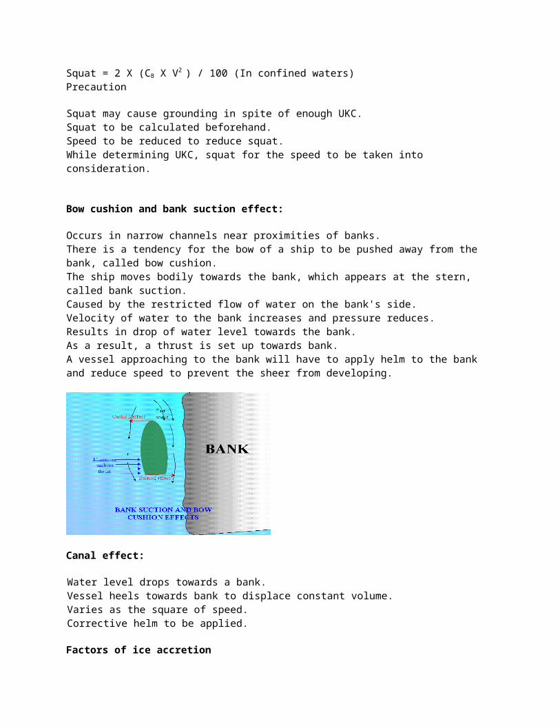
Also a suction effect between the two vessels can pull them together when they are parallel to one another;
One or both vessel could encounter a steering failure or a propulsion failure resulting in a loss of command;
Note: Even though in a narrow channel, the overtaking vessel is not relieved of her obligations under ‘Rule 13’ (Overtaking).
You are in a narrow channel, you hear from astern ‘2 prolonged blasts followed by 2 short blasts’. What is the meaning and what is your action? It means that a vessel astern of me wishes to overtake me on my ‘Port’ side (Rule 34 (c )); My response would be if I considered it safe to do so (Rule 9 (e) (i)) answer by sounding ‘C’; (1
prolonged, 1 short, 1 prolonged, 1 short). And keep to the extreme starboard side of the channel.
It is clear visibility and you are approaching a bend and hear ‘1 prolonged blast’. What does this signal signify? What is your response? The signal signifies that a vessel is approaching the bend from the other side and that her view around
the bend is obscured (Rule 34 (e)); My response would be to also sound ‘1 prolonged blast’ in response to indicate to her that I am aware
she is approaching the bend, and I would keep well to the starboard side of the channel as safely can be maintained.
You are in a narrow channel, constrained by your draft. You see a vessel displaying ‘RAM’ lights on your port bow, bearing steady. What is your action? Sound 5 short blasts to indicate that you are not sure of her intentions; If there is no response, reduce my speed to minimum steerage or if necessary take all way off; Wait for other vessel to be clear, and then proceed with caution until well clear.
You have a “Man Overboard” incident in a traffic separation scheme. What would be your actions? Release the bridge wing man overboard ‘Smoke Marker’; Hit man overboard button on the GPS, take down position; Raise the alarm for man overboard (- - -); Place lookouts to continuously keep man overboard in sight; Raise flag ‘O’, and send a ‘Pan-Pan-Pan’ to warn ships in the immediate vicinity, and also to notify
the Coast Station and the VTS;With great caution execute an ‘Elliptical Manoeuvre’ if practicable; and the speed and method of recovery would greatly depend on traffic density, position of vessel before mishap, visibility, state of sea and most importantly response time to initial alarm raised;
What signals are displayed by a vessel aground? By day: Three ‘Black Balls’ in a vertical line where can best be seen; Also display flags: ‘L’ – Stop your vessel instantly, or ‘U’ – You are standing into danger; By night: Two ‘All Round RED lights’ in a vertical line where best can be seen; Plus the ship’s
anchor light/s;
You see these signals ahead of you. What do you do? Stop engine and go astern; Check chart and positively identify your position; If safe to do so, do a tight turn about and move away on reciprocal course;

Offer assistance to stranded vessel; Broadcast a ‘Nav Warning’ to all ships if one is not already in existence; Observe for any pollution. Use direction and assistance from the VTS.
You have a fire in a cargo hold. What action do you take? At sea: Sound the alarm, all personnel to Muster stations; Contain fire by closing all vents and ventilation leading to the cargo hold; Set up boundary cooling around the hold, including deck and hatches; If hold contains DGs, refer to the EMS Procedures in the IMDG Code. Inform Designated Person Ashore. In Port: Sound the alarm, all personnel to Muster stations; Contain fire by closing all vents and ventilation leading to the cargo hold; Try to extinguish the fire with the onboard FFA; Inform the terminal and port authorities, welcome assistance; If hold contains DGs, refer to the EMS Procedures in the IMDG Code; Inform Designated Person Ashore.Describe a Safe Water Mark? Shape: Spherical, pillar or spar; Colour: Red and White vertical stripes; Light: Isophase, Occulting or LFl.10s/ Morse ‘A’ (. -); Indicates: Navigable water all round the mark, used to mark mid channel or centreline and used to
indicate Landfall.
Describe special marks and what do they indicate? Shape: Optional – can, sphere or cone; Colour: Yellow; Top Mark: Yellow ‘X’; Light: Fl.Y or Fl.Y(4) or any rhythm not used for white lights; Indicates: Spoil ground, military exercises, cable or pipeline, recreation zone, and; If a ‘can shape’ is used leave to port, if a ‘cone shape’ is used leave to starboard and if a sphere shape
is used it is clear all round.
How are new dangers marked? These are used to mark newly discovered dangers to navigation that have yet to be included in charts,
sailing directions and have not yet been addressed in NTM; Marked using one or more Cardinal or Lateral marks; Marks may be duplicated; Lights: Qk or VQk – White for Cardinal marks; Red or Green for Lateral marks; Can have a Racon (coded) or Morse ‘D’ (- . .)
Describe an ‘Isolated Danger Mark’? Shape: Pillar or Spar; ‘BLACK/RED/BLACK’ banded; 2 vertical ‘BLACK’ balls as top mark;
White Light; Group Flash (2).
Where are Isolated Danger Marks erected?
They are erected on, moored on or above an ‘Isolated Danger of Limited Extent’ with navigable water around it;
Note: As safe a wide berth as practicable should be given to these isolated dangers.
What is difference in the preferred channel markers between the Regions?Region A Region B
Preferred Channel to Stbd: Preferred Channel to Stbd: Red can top mark; Green can top mark; Can, pillar or spar; Can, pillar or spar; RED/GREEN/RED horizontal GREEN/RED/GREEN horizontal bands;
bands; Light: Fl(2+1)R; Light: Fl(2+1)G;
Preferred Channel to Port: Preferred Channel to Port: Green cone top mark; Red cone top mark; Conical, pillar or spar; Conical, pillar or spar; GREEN/RED/GREEN horizontal RED/GREEN/RED horizontal
bands; bands; Light: Fl(2+1)G; Light: Fl(2+1)R;
What are the IALA regions ‘A’ & ‘B’? These regions only differ in regards to the side to pass the ‘Lateral’ marks. Also their ‘Top Marks’ are different in the regard that they signify the way the mark is to be left
when approaching from seaward; e.g. in Region ‘A’ the top mark for the ‘Port hand Red marker’ has a ‘Can’ shape; and the ‘Starboard hand Green marker’ has a ‘Cone’ shape;In Region ‘B’ the top mark for the ‘Port hand Green marker’ has a ‘Can’ shape; and the ‘Starboard hand Red marker’ has a ‘Cone’ shape; “i.e the shape doesn’t change but the colour does”;
Region ‘A’: The Lateral Buoyage marking channels is ‘Red to Port’ related to the Conventional Direction of Buoyage. Off the coast, the direction of buoyage in this region is from ‘East to West’; within the estuary, it is the direction taken by the mariner when approaching from seaward;
Region ‘B’: The Lateral Buoyage marking channels is ‘Red to Starboard’, related to the Conventional Direction of Buoyage. Off the coast, the direction of buoyage in this region is from ‘East to West’; within the estuary, it is the direction taken by the mariner when approaching from seaward.
It can also be looked at that in ‘Region ‘A’ when entering port it is ‘Red to Port’ and ‘Green to Starboard’. When leaving port it is ‘Green to Port’ and ‘Red to Starboard’;And in ‘Region ‘B’ when entering port it is ‘Green to Port’ and ‘Red to Starboard’. When leaving port it is ‘Red to Port’ and ‘Green to Starboard’.
Both regions’ Lateral marks/buoys can be either cans, cones, pillars or spars.
A cardinal buoy has lost its top mark. How do you identify it? What are the light characteristics? Cardinal marks are painted black and yellow, the top marks if fitted are black triangles and the light is
white; NORTH: ‘Black Top’ and ‘Yellow Bottom’; LIGHT: Qk Fl or VQk Fl; EAST: ‘Black Top’, ‘Yellow Centre’, ‘Black Bottom’; LIGHT: Qk Fl (3)10 sec or VQk
Fl (3) 5 sec;

SOUTH: ‘Yellow Top’ and ‘Black Bottom’; LIGHT: Qk Fl (6) + L.Fl 15 sec or VQk Fl (6) + L.Fl 10 sec;
WEST: ‘Yellow Top’, ‘Black Centre’, ‘Yellow Bottom’; LIGHT: Qk Fl (9) 15 sec or VQk Fl (9) 10 sec.
You are on watch and you see a cardinal mark ahead. Which direction do you pass? All cardinals indicate that the best water is on the same side as indicated by the mark; e.g. a ‘North’
cardinal mark is indicating that the best water is to the ‘North’, so you would pass north of the mark; Pass ‘North’ of a ‘North’ mark; Pass ‘East’ of an ‘East’ mark; Pass ‘South’ of a ‘South’ mark; Pass ‘West’ of a ‘West’ mark.
What are the regulations regarding Oily Water Separators? What happens when the PPM is exceeded? Firstly; MARPOL Annex 1 applies to all tankers over 150grt and other vessels over 400grt. The certificate issued is the International Oil Pollution Prevention Certificate (IOPP), and is valid for
5 years, with an Annual inspection; The oil content of effluent discharged overboard from machinery spaces only, must satisfy the
following:1. cannot exceed 15ppm, with vessels over 400grt required to be fitted with 15ppm filtering and
detection equipment;2. not within special areas;3. not within 12nm of land;4. En-route (vessel must be making way);5. Effluent not to contain residues from cargo or pump room spaces.
Secondly; Filtering equipment on vessels over 10,000grt, when the 15ppm limit is reached, must have;1. Alarm arrangements;2. Automatic stopping devices; usually the discharge valve shuts and the effluent is circulated
back to the space.
What are the special requirements of inflatable lifejackets? Must be capable of inflation by a single manual motion (pull cord and CO2 bottle); Must be capable of inflation by mouth; Must have two separate buoyancy compartments; Must have sufficient buoyancy and stability in calm water to:
1. Lift the mouth and head of an unconscious person not less than 120mm clear of the water, with the body inclined backwards at an angle of not less than 20deg, and not more than 50deg from the vertical position;
2. Turn an unconscious person from any position to where the mouth is clear of the water in not more than 5 seconds;
Must have the similar characteristic of non-inflatable jackets in that they must be able to be donned in 1 minute without assistance;
Comfortable to wear; Buoyancy not reduced more than 5% after 24 hours in fresh water; Not to sustain burning or continue melting after being totally enveloped in a fire for 2 seconds; Carry enough lifejackets onboard for every person + 10% spare; Additional lifejackets to be carried in working spaces, including Bridge, E/R, Forecastle and at the
lifeboat stations (These must be stowed in float free lockers with hydrostatic releases).

What do you know about the visual distress signals? The ‘Hand and Parachute Flares’ must be kept in a waterproof container; All signals must be supplied with full instructions on safety and use; They must not be explosive on ignition; The ‘Hand Flares’ must burn for a minimum of 1 minute at 15,000 candela and have a 3 year life; The ‘Parachute Flares’ must reach an altitude of 300m, burn for a minimum of 40 seconds at 30,000
candela and have a 3 year life; An ‘Orange Smoke Float’ must emit orange smoke for a minimum of 3 minutes and have a life of 3
years; A ‘Self Activated MOB Orange Smoke Float’ must emit orange smoke for a minimum of 15 minutes
and have a life of 3 years; Lifebuoy Lights must light for a minimum of 2 hours at 2 candelas with all round visibility; A Lifejacket Light must light for a minimum of 8 hours at 0.75 candelas with all round visibility.
What is a Thermal Protective Aid (TPA)? It is a bag or suit made from waterproof materials with low thermal conductivity; It shall reduce both convective and evaporative heat loss from the wearer’s body; Shall be capable of covering the whole of the wearer’s body when wearing a lifejacket, but with the
exception of not having to cover the persons head; Shall capable of being unpacked and easily donned without any assistance in a survival craft or rescue
boat; Permit the wearer to remove it in the water in not more than 2 minutes, if it is impairing the wearer’s
ability to swim; Shall function properly throughout air temperatures between -30deg C and + 20deg C.
What do you know about Immersion Suits? This is a suit designed to protect the wearer from loss of body heat when immersed in cold waters,
and constructed from waterproof materials; Shall be able to be unpacked and donned without assistance within 2 minutes; Shall cover the whole body with the exception of the face; hands shall be covered unless permanently
attached cloves are provided; It shall be provided with arrangements to minimise the amount of free air in the legs of the suit to stop
the wearer being unbalanced in the water; Following a jump into the water from a height of 4.5 metres there is to be no ingress of water into the
suit; Must be fitted with retro-reflective tape; Must allow the wearer to don a lifejacket without assistance; NOTE: Some types of Immersion Suits are buoyant, and are classed as lifejackets. In that case
the suit has to be equipped with a light and a whistle.
How is a rescue boat equipped? A sufficient amount of buoyant oars or paddles to make headway in calm seas; A buoyant bailer; An illuminated efficient compass; A sea anchor and tripping line, with a hawser not less than 10m in length; A painter attached to a release device placed at the forward end of the craft;

A buoyant line not less than 50m in length and strong enough to tow a liferaft; Waterproof torch, spare batteries and bulb in a waterproof container; A whistle or other sound signalling device; First aid kit; 2 buoyant rescue quoits with not less than 30m of buoyant line attached; Radar reflector or a radar transponder; TPA for 10% of persons or 2; whichever is the greater; Searchlight capable of illuminating an object having a width of 18m at a distance of 180m for a total
period of 6 hours, 3 of which must be continuous illumination.
Additionally a ‘Rigid Rescue Boat’ must have: A boat hook; A bucket; A knife or hatchet,
And an ‘Inflatable Rescue Boat’ must have in additional to normal requirement: A buoyant safety knife; 2 sponges; Manually operated bellows pump; Repair kit; Safety boat hook.
What is a rescue boat and what are the requirements? Basically any boat that meets the requirements. The rescue boat is used for recovery of persons from
the water. And for rounding up liferafts after abandoning ship.General requirements: Either rigid or inflatable or a combination of both (rigid inflatable); Length not less than 3.8 metres, and not more than 8.5 metres; Capable of carrying at least five personnel seated, and one lying down; Construction of rigid and inflated shall comply with the requirements of the flag state Administration; Unless the boat has adequate sheer, it shall be provided with a bow cover extending not less than 15%
of its length; Capable of manoeuvring at speeds up to 5 knots and able to maintain that speed for 4 hours; Launching and recovery of the rescue boat must not obstruct the operation of a lifeboat; Capable of being launched when the ship is making headway of up to 5 knots; Rapid recovery with full compliment and all equipment on board; Cargo ships to have at least one rescue boat; Passenger ships of 500grt or more to have at least one rescue boat on each side; Passenger ships of less than 500grt to have at least one rescue boat.
You are on watch at night, bridge doors closed, how would you ascertain if the vessel is encountering fog? Venture out to both bridge wings and observe the atmosphere. Also look at own lighting to see if a
halo has formed around them; Check the radar and observe the range of targets you should be able to see clearly by eye; Again go out onto bridge wings and if they are not visible by eye, you can say you are in fog, about
to enter fog, or fog is closing in on you.
You have a small fire in the E/R bilge. How do you fight it?
Raise the alarm; Use a portable Foam, Dry Powder or CO2 extinguisher to initially attempt to extinguish the small fire
in its infancy.It has now become too large a fire. What do you do now? Stop engine and evacuate the engine room; Display NUC signals; All personnel to Muster Station; Headcount; By now the fire parties should be closed up as a reaction to initially raising the alarm; Close all ventilation, dampers, remote closing valves and remote quick closing fuel shut-offs; On orders from the Master release the CO2 System; Rig boundary cooling; Follow SOPEP for reporting procedures and contingencies; Inform Designated Person Ashore; Set up temperature gauges on E/R boundaries and monitor situation.
What is a Combined Lantern? What size vessel can display it? Can you have the stern light in the Combined Lantern? This lantern has the ‘Port & Starboard’ side lights and the “Stern Light” combined in the same
lantern. The arcs of visibility for each light are as per the requirements of the rules; Can be carried by a ‘Sailing Vessel’ less than 20m in length, and fitted at or near the masthead where
it can best be seen. The combined lantern cannot be exhibited in conjunction with any other navigation lights.
How many fire extinguishers is life boats required to carry, and what extinguishing agent can be used and what type of fire are they required to extinguish? Motor Life Boats on foreign registered vessels require one portable extinguisher for oil fires; Australian registered vessels require 2 portable extinguishers, one for oil fires and one for material
fires i.e. 1 x 4.5Ltr Foam + 1 x 2.25kg Dry Powder.
On a chart, a light is shown as 20M. What does this indicate?
It means 20 miles is the ‘Nominal’ maximum range at which the light can be seen in conditions where visibility is 10nm.
Name the periods of drills you are required to carry out? Fire; collision, abandon ship and SOPEP drills at least one a month. Rescue boat with assigned crew – every month; Marine evacuation system – no longer than 2 yearly; Familiarize safety installations and practice muster – before voyage; Passengers onboard for more than 24 hours – within 24 hours of embarkation. Crew must participate
within 24 hours also if more than 25% of crew changed; Lifeboat drill by turning out the boats every month, and all boats launched and run every 3 months.
Must conduct a drill within 24 hours of sailing if the crew has changed by more than 25%; Davit launched life rafts – not more than 4 months; Emergency steering gear drill – not more than 3 months.
What is a SART, and where would you find information on them? A Search and Rescue Transponder, and they are a battery powered radar detecting position indicating
device. Therefore on receipt of a radar signal from an aircraft or ship, the SART will respond by

transmitting a signal which shows up on the radar screen as a series of 12 small arcs extending about 5 nm outwards from the SART’s position along its bearing line;
It operates in the 10 GHz (9.3 – 9.5GHz) frequency range, and responds to radar operating in that same range (3cm radar);
The battery allows the SART to stay on stand-by waiting for a radar signal to respond to for 96 hours. Information on SARTs is in the Annual Notices to Mariners, and the SART manual itself.
You are on watch when the visibility unexpectedly drops to a few meters. What immediate action will you take? Call the Master; Activate appropriate fog signal; Reduce speed; Post look-outs forward and on bridge wings; Helmsman to standby on bridge; Have engines ready for manoeuvre; Both radars on and working continuously on the appropriate scales; Plot position and proceed with caution; Check for Nav Warnings.
What are the differences between a narrow channel and a TSS? TSS: NARROW CHANNEL1. The direction of traffic flow specified. Keep to Starboard side of channel.2. Overtaking Rules apply. Overtaking Rules apply.3. No sound signal at a bend. Sound signal at a bend applies for
Vessel’s not in sight of one another.4. Cross at right angles. Normal rules apply.5. Join & Leave at minimum angle. Join & Leave as required safe nav.6. Anchor in an emergency only. Anchor in an emergency only.7. Normal rules apply during dredging. Dredging exempt from normal rules.8. Fishing v/l not to impede deep draft v/l Fishing v/l not to impede deep draft v/l.
What is SOLAS? It is the International Convention on Safety of Life at Sea. And is made up of the following Parts and
Annexes: Part 1: Contains the 74 Convention and 78 Protocol Articles, also has the Requirements and
Certificates Required. Part 2: Implementation of the Harmonized System of Survey and Certification. Lists of Certificates
and Documents to be carried onboard Ships and the resolutions of the 1994/95 Conferences. Also contains the new Chapter IX, being the International Safety Management Code (ISM) for the safe management, operation and pollution prevention of ships.
What do you know about Bridge Resource Management? Basically it is to have the Bridge team including the Master and Pilot pooling their skills and training
to work the bridge as a team for the common navigation safety of the ship. They should professionally challenge each other on actions of concern to them with regards to the passage plan. The roles of each team member are clearly defined, and they interact with each other. The Master should be stood back overseeing the operation of the team in executing the passage plan.
With regard to the ISM Code, who is the designated person? He is the designated direct link between the ship and shore; he is required to have direct
unconditional access to the highest level of management of the company.
What is the responsibility of a ‘Power Driven” vessel towards other vessels?A power driven vessel gives way to: A vessel ‘Not under command’ A vessel ‘Restricted in her ability to manoeuvre’ A ‘Sailing vessel’ A vessel ‘Engaged in Fishing’.
What is the fog signal for a vessel at anchor? A vessel less than 100m in length shall sound rapid ringing of the bell for 5 sec at 1 minute intervals. A vessel over 100m in length shall sound in the fore part of the vessel, the rapid ringing of the bell for
5 sec, followed immediately from the aft section by the sounding of the gong for 5 sec at 1 minute intervals.
A vessel in giving warning of her position and possible collision may sound in Morse ‘R’ (1 short-1 long-1 short).
What is a ‘Ground Stabilized’ display? GROUND STABILISATION: A stationary target is acquired as a reference, or an input from a
GPS/DGPS or Doppler log is used. This ground stabilizes the display in true motion to give own ship, and target ship’s course and speed over the ground. Can be useful in coastal navigation to calculate set and drift or leeway. Not recommended for collision avoidance.
What are the essential elements of an approved ARPA? Minimum screen diameter of 340mm. Raster Scan display only. Manually and automatically acquire and track at least 20 targets. Must have both True and Relative vectors with the length operator adjustable. Must have North Up and Course Up presentations. Provide course, speed, CPA, TCPA range and bearing of tracked targets. Full accuracy of tracked target’s data available after 3 minutes. Operator alarms and alerts must be fitted. Trial manoeuvre facility must be fitted Past track history must be available for all tracked targets.
What are some of the ‘Errors in Interpretation’ with regards to ARPA? VECTOR MODE: you must always be aware of the vector type on display. Whether the mode is
True or Relative vectors will indicate different things. True vectors give the true course and speed of the other vessel through the water and not it’s true aspect. Where as Relative vectors give the relative motion of both vessels to each other, the CPA and TCPA.
SPEED & COURSE INPUTS: Speed and course errors can occur when there are log and gyro errors. Ship’s own course and speed inputs are used by the ARPA to calculate the vectors, and eventually CPA and TCPA. As collision avoidance is based around headings the system needs to be Sea stabilised and not ground stabilised. Therefore it requires a log detecting speed through the water and not over the ground.
PAD DISPLAYS: PADs do not indicate the vector of the targets speed. The centre of the PAD is not the PPC; PADs also do not show CPA. So care must be taken when using PADs.
GENERAL PRECAUTIONS: Care must be taken when evaluating information, do not act on scanty information. Be aware of what motion is on display, True or Relative. Know any ‘OFF SET’ in use. Be aware of weak targets, small targets, and very fast moving targets. Use Sea and Rain clutters with care not to obliterate close in targets. Do not clutter up the screen with too much information e.g. PADs, vectors, PIs, clearing lines,
Electronic chart overlays, trails, Nav lines, waypoints, etc.
What is the purpose of past track information? To show to the operator the recent tracks or manoeuvres of targets. It is history; so they really show
what a target has done and not what it is doing. Shows it by a series of dots trailing the target. Dot spacing can indicate changes in speed, and their curvature will indicate recent manoeuvres.
What is the function of the trial manoeuvre facility? If predicted far enough in advance that a close quarters situation is developing, then the Trial
Manoeuvre facility can be used to trial course and speed alterations with a delay to assist the decision making process in avoiding the close quarters situation .
When trial manoeuvre is on, it is indicated by a ‘T’ at the bottom of the screen. If true vectors are displayed, then own ships vector will change direction or length as appropriate. If relative vectors are displayed then the relative vectors of the targets will alter direction and course
from the delayed time inputted. This gives an instant visual appreciation of the CPA as a result of the trial manoeuvre.
What will ‘Lost Target” tell you? If a tracked target is lost, then a warning must be given by the ARPA. Tracker will continue to search for it, and may re-acquire the target and continue to give vectors. Caution on re-acquired vector of lost target is that the information is not reliable for at least 3
minutes.
How could you acquire a target? Manual Acquisition: First you set the parameters required i.e. CPA, TCPA.Then change to True Vectors to get a general view of the flow of the traffic. Change back to Relative Vectors, place curser over required target/s, Press Manual Acquire. In 1 minute there will be preliminary data available, but after 3 minutes you will get accurate data as to other target’s Course, Speed, CPA, TCPA, and Aspect. An ARPA must be able to acquire up to 20 targets either Automatically or Manually. Automatic Acquisition: Can either acquire them in a Global Form; i.e. by setting a distance right
around the vessel and setting the ARPA to automatically acquire targets encroaching inside this area. Or by setting up Zones by setting Guard Rings say only forward of the beam, or forward of starboard beam to right ahead as an example. The ARPA would then Automatically acquire targets encroaching on those zones.
What is the function of Target Swap and Echo Loss? If target is lost after the smoothing process, the gate will open up further until it finds the target again
to save loosing the target.
What are the different formats in which the data is displayed?
Relative Motion: In Relative motion the vector matrix value can be displayed on the screen in time intervals. The vector lengths are operator adjustable and time related, so the vector can be extended to give a visual representation of the CPA. Own ship will not have a vector.
True Motion: In True Motion the vector lengths are also operator adjustable and time related, so can be extended to visually show the CPA. The difference is that your own ship has a True Vector and the CPA is the difference between the two vectors. It will also show weather the vessel will pass astern or ahead of you. It is also possible to detect the true movements of other vessels around you besides the one you are concerned with.
What is the data displayed by an ARPA? After 3 minutes gives accurate display of other targets Course, Speed, Range, CPA, TCPA and
Aspect. Shows either True or relative Vectors. Will give information on a trial manoeuvre.
What actions would you take in the event of an oil spill? Sound the general alarm and cease all bunkering operations. Containing the oil spill on deck is the major priority. Form a bund around the spill. Execute the SOPEP Have oil spill booms ready. Inform the appropriate authority. Use assistance of oil response teams if required. If oil does get over the side, deploy booms, use local assistance, and under no circumstances use any
chemical dispersants. Clean up under direction of local oil response team commander. Log all actions. File a report; get independent statements of facts from all involved.
You are going to bunker, how would you prevent an oil spill? Refer to the ships approved SOPEP Manual. Refer to the bunkering procedures manual and checklists. Ensure the ship is upright at commencement. Hold a pre-bunkering meeting and have a bunkering plan in place. Maximum list to any side
established, this is not to be exceeded during bunkering operations. Prepare deck as per bunkering checklist:
1. Scuppers plugged and cemented.2. All vent save-alls cleaned and clear.3. SOPEP equipment on hand, i.e. kitty litter, pads, absorbent materials etc.4. Check all fittings and hoses, gaskets.5. Drip trays under any hose joints.6. Joins kept to a minimum7. Display Flag ‘B’ and ‘RY’ flags.
Describe the complete start up, set up and operation of the ship’s radar? Check antenna so that no person is aloft, any lanyards, flags or other rigging is not fouling the
scanner. Switch from mains source is ON. Set all controls to zero. Switch radar on and weight the tree minute warm-up to take place. Switch from standby to transmit

Set range scale (usually the 12nm), brilliance, gain, and tune the set. Fine tune If required set the sea clutter: Sea clutter suppresses the sea echoes by using the swept gain,
that is an automatic and gradual increase in amplification of each pulse echo from low levels for early echoes to full level for later echoes. Care to be taken not do obliterate small targets and targets at close range.
Also if required set the rain clutter, bearing in mind not to obliterate targets.
Ship handling – Right Hand Prop, describe a ‘Short Round Turn’ in a river. Which way would you turn and why? This is taking advantage of transverse thrust. And for a RH turning screw you would hug the ‘Port’
side of the river keeping enough clear water for the stern to swing in. Whilst at slow ahead; put the rudder hard-a-starboard and as soon as it reaches full deflection put engine full ahead. As the ship arcs toward other side of the river and at a safe distance from the opposite bank, stop engine, put rudder amidships, put engine full astern. This will utilise the transverse thrust and set the stern to port and bow to starboard. At a safe point, stop engine, put rudder hard-a-starboard, put engine full ahead. Repeat process as necessary to get your ship safely moving in the opposite direction within the confines of the river. Use appropriate manoeuvring signals.
All the best.
Ramiah Selvarajan.