Orakei Main Sewer Rehabilitation
10
LUDLOCK.DOCX 18/05/2015 09:48:58 Page 1 /10 P:\CURRENT\IPWEA 2015\PAPERS\LUDLOCK.DOCX Orakei Main Sewer Rehabilitation Authors Maurice Lubbock ‐ Associate Director, AECOM New Zealand Ltd Warwick Brown ‐ Project Engineer, Watercare Services Ltd Abstract The Orakei Main Sewer, varying in size from 525mm circular to 2.4m x 1.5m egg shape, was originally constructed in 1910, and runs from Avondale, via Herne Bay and onwards to Hobson Bay, a total of over 8 km. A 250m section of egg shaped concrete block construction 2.4m x 1.5m runs under the Stanley St motorway on ramp, through the Auckland Domain, and under the ASB tennis centre. Even once the Central Interceptor comes on stream, starting in the mid‐late 2020s, this sewer will continue to be a critical and essential component of Auckland’s sewer network. Following extensive investigation, it was found that the structural integrity of the crown arch had become compromised due to biogenic corrosion and root intrusion, and that it had reached a level where structural repairs could not be deferred without incurring unacceptable risk. After design and tendering, a project was undertaken to install 150m of glass reinforced lining segments and a further 100m of CAC mortar lining where the condition of the main sewer was of greatest concern. To carry out the lining works, a temporary pump station and rising main were built, to divert flows of up to 800 l/sec. This 12 month project was successfully completed without incident in July 2014. Keywords Sewer Rehabilitation Egg shape GRP sliplining Flow management High modulus reinforcement Sewpercoat®
Transcript of Orakei Main Sewer Rehabilitation

LUDLOCK.DOCX 18/05/2015 09:48:58 Page 1 /10
P:\CURRENT\IPWEA 2015\PAPERS\LUDLOCK.DOCX
Orakei Main Sewer Rehabilitation Authors
Maurice Lubbock ‐ Associate Director, AECOM New Zealand Ltd Warwick Brown ‐ Project Engineer, Watercare Services Ltd Abstract
The Orakei Main Sewer, varying in size from 525mm circular to 2.4m x 1.5m egg shape, was originally constructed in 1910, and runs from Avondale, via Herne Bay and onwards to Hobson Bay, a total of over 8 km. A 250m section of egg shaped concrete block construction 2.4m x 1.5m runs under the Stanley St motorway on ramp, through the Auckland Domain, and under the ASB tennis centre. Even once the Central Interceptor comes on stream, starting in the mid‐late 2020s, this sewer will continue to be a critical and essential component of Auckland’s sewer network.
Following extensive investigation, it was found that the structural integrity of the crown arch had become compromised due to biogenic corrosion and root intrusion, and that it had reached a level where structural repairs could not be deferred without incurring unacceptable risk.
After design and tendering, a project was undertaken to install 150m of glass reinforced lining segments and a further 100m of CAC mortar lining where the condition of the main sewer was of greatest concern. To carry out the lining works, a temporary pump station and rising main were built, to divert flows of up to 800 l/sec.
This 12 month project was successfully completed without incident in July 2014.
Keywords
Sewer Rehabilitation Egg shape GRP sliplining Flow management High modulus reinforcement Sewpercoat®

LUDLOCK.DOCX 18/05/2015 09:48:58 Page 2 /10
P:\CURRENT\IPWEA 2015\PAPERS\LUDLOCK.DOCX
1. INTRODUCTION
This paper describes the renewal of a 250m section of Watercare’s Orakei main sewer, located between MH21 and MH19, as shown in Fig 1 below.
This work will extend the life of the sewer section by a minimum of fifty years. Before then, Watercare’s Central Interceptor will have been built, and will provide redundancy and improved ease of flow management in older parts of the network, to facilitate similar future remedial works.
Figure 1 ‐ Orakei Main sewer MH21‐ MH19
This section is currently a critical part of Auckland’s wastewater network. A failure here would risk a major overflow to the Waitemata Harbour, via engineered overflow points, and worse, significant overflow from the lowest manholes upstream, with attendant flooding, environmental damage, and risks to public health.
Watercare’s Wastewater Transmission Operations team manages the wastewater transmission network, including 329 km of large sewers (Ø>400 mm) and 56 pump stations. The condition assessment programme for large sewers includes CCTV, laser and sonar profiling and walk‐through visual inspections. The inspection and condition assessment frequency depends on the condition and criticality of a particular sewer asset; the more critical the asset, the more intensive the condition assessment.
All pipeline assets are assessed for condition against standardized criteria and scoring systems, in line with WRC recommendations. Watercare has graded its most important sewers for criticality against a scoring system similar to that used for asset condition.
The Orakei Main Sewer is one of the oldest sewers in the transmission network. Its age and style of construction increases the emphasis required on timely inspections, and careful and responsible management of its condition.
In 2009Watercare carried out a boat‐mounted CCTV inspection, which identified a significant tree‐root intrusion along the spring line between Manhole 21 and Manhole 19.

LUDLOCK.DOCX 18/05/2015 09:48:58 Page 3 /10
P:\CURRENT\IPWEA 2015\PAPERS\LUDLOCK.DOCX
Figure 2 ‐ Root Intrusions
Root intrusion as seen from CCTV boat Ploughing
The Operations team determined that these roots posed a risk to sewer ploughing operations routinely used to clean the accumulated grit from the sewer, since the plough guide wheels could jam on them.
Watercare then carried out an entry to remove these tree roots, and to carry out routine maintenance. In the course of this work, the crew observed that sections of the blockwork arch in this section were showing signs of distress, profile deformation, and losing material. Subsequent walk‐through inspections by the Operations team determined that there was indeed cause for concern, and hence AECOM were engaged to provide professional engineering advice and support to Watercare on the issue.
Watercare’s regular inspection process showed that the sewer structure in this section had reached the point at which rehabilitation work could not be deferred any longer, at an acceptable risk level. Having reached this conclusion, Watercare initiated an investigation project in 2010, with the following objectives
• obtain more accurate and comprehensive condition data for the rehabilitation project
• determine the extent in which repairs were necessary
• provide an assessment of the options available for the physical remediation project.
2. INVESTIGATION PROJECT
The Orakei main sewer was constructed in 1910 as a 2.4m x 1.6m egg shape.
Cast in place concrete was used for the invert and wall sections, and the crown was made from trapezoidal concrete blocks. Between MH21 and MH19 the sewer was built under three separate contracts, with clearly visible differences in the standard of construction in the different contract sections.
Two types of concrete blocks used, with McCallum chip and basalt aggregate. The basalt chip blocks were found to be much more easily corroded than the McCallum chip blocks, and were easily broken up when tested with a water jet. They were also found to be riddled with air pockets. The manufacture of these blocks was evidently of low quality.
Consequently, there were extensive stretches of soft blockwork, which could be chipped with little effort, using hand tools. Core sample testing found compressive strengths as low as 8 MPa, and loss of alkalinity to depths of 50%.
The mortar pointing between blocks was severely degraded or missing completely throughout the section.

LUDLOCK.DOCX 18/05/2015 09:48:58 Page 4 /10
P:\CURRENT\IPWEA 2015\PAPERS\LUDLOCK.DOCX
As shown in Figure 3, there were many blockwork joints with no mortar at all, and the blocks in these areas were held together purely by the surrounding soil pressure. Large volumes of water and silty debris were seen to be infiltrating via these defective joints.
The hydraulic conditions immediately downstream of the curve at the western end of Grafton Mews also resulted in rapid accumulation of silty debris, so that Watercare found it necessary to run the plough cleaning device through this section at approximately 2 yearly intervals.
Figure 3 ‐ ORM Structure and corrosion damage
Cross section Spalling of block arch crown
Degraded mortar & profile deformation Degraded pointing
Another effect of the gaps between blocks was to encourage the growth of tree roots, as seen in Figure 2. The most probable origin of these roots was the willow tree immediately above the location of the worst infestation, but this could not be proved conclusively. Nevertheless, Watercare were obliged to operate a programme of planned trimming of these roots, some or which reached diameters of 50mm or more between trimming passes.
Probably the most serious issue noted was that the crown arch had begun to show deformation in the areas worst affected by corrosion damage, coincident with the Willow tree adjacent to Grafton Mews.
Previous repair attempts had included localised patching with corrosion resistant mortar, but these were found to be ineffective, as the underlying substrate continued to corrode around and beneath them. In some places, these repair patches had already spalled and detached.
Options considered for renewal
• Tunnelled replacement pipe
LUDLOCK.DOCX 18/05/2015 09:48:58 Page 5 /10
P:\CURRENT\IPWEA 2015\PAPERS\LUDLOCK.DOCX
• CIPP relining
• Gunite CAC relining
• Sliplining
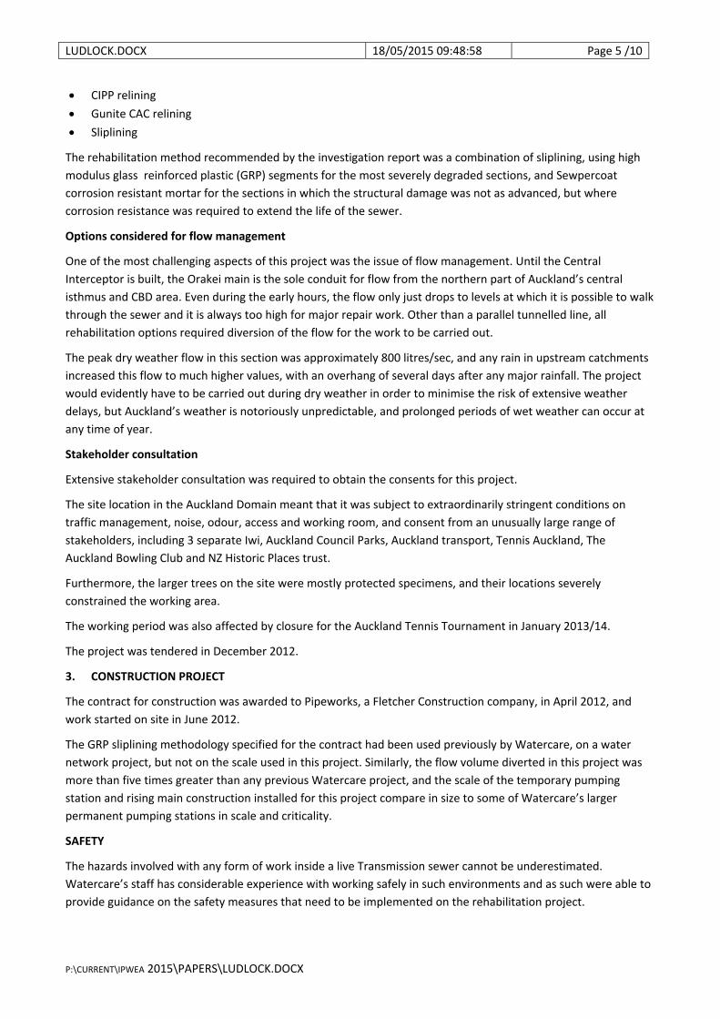
The rehabilitation method recommended by the investigation report was a combination of sliplining, using high modulus glass reinforced plastic (GRP) segments for the most severely degraded sections, and Sewpercoat corrosion resistant mortar for the sections in which the structural damage was not as advanced, but where corrosion resistance was required to extend the life of the sewer.
Options considered for flow management
One of the most challenging aspects of this project was the issue of flow management. Until the Central Interceptor is built, the Orakei main is the sole conduit for flow from the northern part of Auckland’s central isthmus and CBD area. Even during the early hours, the flow only just drops to levels at which it is possible to walk through the sewer and it is always too high for major repair work. Other than a parallel tunnelled line, all rehabilitation options required diversion of the flow for the work to be carried out.
The peak dry weather flow in this section was approximately 800 litres/sec, and any rain in upstream catchments increased this flow to much higher values, with an overhang of several days after any major rainfall. The project would evidently have to be carried out during dry weather in order to minimise the risk of extensive weather delays, but Auckland’s weather is notoriously unpredictable, and prolonged periods of wet weather can occur at any time of year.
Stakeholder consultation
Extensive stakeholder consultation was required to obtain the consents for this project.
The site location in the Auckland Domain meant that it was subject to extraordinarily stringent conditions on traffic management, noise, odour, access and working room, and consent from an unusually large range of stakeholders, including 3 separate Iwi, Auckland Council Parks, Auckland transport, Tennis Auckland, The Auckland Bowling Club and NZ Historic Places trust.
Furthermore, the larger trees on the site were mostly protected specimens, and their locations severely constrained the working area.
The working period was also affected by closure for the Auckland Tennis Tournament in January 2013/14.
The project was tendered in December 2012.
3. CONSTRUCTION PROJECT
The contract for construction was awarded to Pipeworks, a Fletcher Construction company, in April 2012, and work started on site in June 2012.
The GRP sliplining methodology specified for the contract had been used previously by Watercare, on a water network project, but not on the scale used in this project. Similarly, the flow volume diverted in this project was more than five times greater than any previous Watercare project, and the scale of the temporary pumping station and rising main construction installed for this project compare in size to some of Watercare’s larger permanent pumping stations in scale and criticality.
SAFETY
The hazards involved with any form of work inside a live Transmission sewer cannot be underestimated. Watercare’s staff has considerable experience with working safely in such environments and as such were able to provide guidance on the safety measures that need to be implemented on the rehabilitation project.

LUDLOCK.DOCX 18/05/2015 09:48:58 Page 6 /10
P:\CURRENT\IPWEA 2015\PAPERS\LUDLOCK.DOCX
Some of these measures included:
• personnel working in section downstream of major flow diversion required exhaustive analysis of flow management plan
• separate flowmeters on each riser leg
• double stop logs
• rigorous flow monitoring, full time pump watch, Practice evacuation,
• Independent external audit by Compliance Australia Certification Services
As part of the contract, approval to operate the pumps or enter the sewer in any way required prior approval from Watercare Transmission Operations who regularly assessed the weather forecast and sewer flows using SCADA. Watercare will not permit work in any of its sewers if there is a risk of heavy rain that could increase the flows. Operations, through their experience, have a very good understanding of the flow level criteria that allows for safe entry into the sewer. Decisions around weather were at Operations’ sole discretion.
The flow management plan for this project was exhaustively reviewed and tested, to ensure that it would adequately cover all aspects of the operation of the temporary flow diversion system, and fully provide for safe working inside the reach between MH21 and MH19. Extensive calculations were carried out to estimate the time available for evacuation of the working reach in the event of pump failure, and in the worst case, there would have been at least one hour available.
Once the system was functional, these calculations were verified by testing the system over a full range of flow conditions tested. During the period of several months in which the system operated, there was only one single occasion when it was necessary to carry out a precautionary evacuation, as the result of one or the five separate pumps stopping. At no time were the pumps unable to keep ahead of the incoming flow during programmed working hours.
Odour Control
Odour turned out to be less of an issue with this project than we had anticipated. The contract schedule and specification allowed for the procurement of large scale filtering and physical isolation measures, but in the event, the odour nuisance was managed effectively by a combination of ventilation and chemical dosing. No significant complaints were received about odour, despite the site location in a very sensitive area, and the volume of passing traffic.
Flow Management
In order to enable entry to the sewer to carry out the installation of GRP segments and corrosion resistant mortar, it was necessary to construct an entire temporary pumping station and rising main, capable of diverting up to 800 litres/sec over a distance of about 250m, via a Ø630mm SDR17 polyethylene pipeline, including a section of 150m within the grounds of the Auckland Tennis Centre.
The suction and discharge elevations of this diversion were the same, and the maximum elevation above the wet well was approximately 6m. The capacity of the system when it was commissioned turned out to be about 4% more than the design value.
The wet well, construction required the excavation and stabilisation of an 8m deep chamber, approximately 12m long by 5m wide, immediately adjacent to Auckland’s Stanley St motorway on ramp, the Orakei main sewer, and a fragile 2m brick stormwater culvert, as well as numerous other smaller services. The methodology used was to install king piles, with timber lagging. A 20ft steel shipping container was installed within this shored excavation, to provide a watertight chamber in which five separate submersible pumps were installed.

LUDLOCK.DOCX 18/05/2015 09:48:58 Page 7 /10
P:\CURRENT\IPWEA 2015\PAPERS\LUDLOCK.DOCX
It was also necessary to provide for diversion of incoming flows (approx. up to 130 litres / sec) via the DPS013 rising main. An innovative solution was developed, by extending the DPS013 rising main, so that it discharged into the temporary wet well, at a lower discharge elevation, so that load on the DPS013 remained unchanged and the station could operate normally, with no need for extra pumps, flow metering, or owner notifications. This diversion operated flawlessly throughout the project.
The first part of the temporary rising main was constructed during 2013, to allow for testing of the pump battery, and passage of a sizing spool through the upstream end of the sewer section, as required to verify the exact physical dimensions of the deformed parts of the sewer profile.
Once the wet well had been built, it was then necessary to cut into the fragile structure, so that flow could be diverted from the OMS into the temporary wet well. A reinforced concrete shell was cast around the existing crown section of the sewer, before it was wire cut and gently lifted, to provide access.
A double stop log was then installed at the downstream end of the opening, to divert flow into the wet well at the upstream end.
A hinged stop log was installed at the downstream end to stop the diverted flow re‐entering the working reach from the downstream end.
Figure 4 ‐ Flow diversion wet well and cut‐in
Wet well Cut‐in
The site was closed in December 2013 and January 2014 for the ASB tennis tournament. When work resumed, the remaining rising main pipework was installed. When the pumping station was tested, its capacity was found to be 4% above the design value.
LUDLOCK.DOCX 18/05/2015 09:48:58 Page 8 /10
P:\CURRENT\IPWEA 2015\PAPERS\LUDLOCK.DOCX
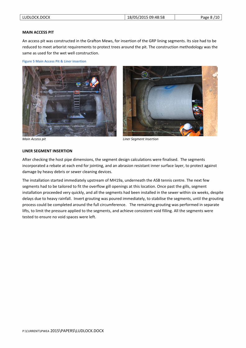
MAIN ACCESS PIT
An access pit was constructed in the Grafton Mews, for insertion of the GRP lining segments. Its size had to be reduced to meet arborist requirements to protect trees around the pit. The construction methodology was the same as used for the wet well construction.
Figure 5 Main Access Pit & Liner insertion
Main Access pit Liner Segment Insertion
LINER SEGMENT INSERTION
After checking the host pipe dimensions, the segment design calculations were finalised. The segments incorporated a rebate at each end for jointing, and an abrasion resistant inner surface layer, to protect against damage by heavy debris or sewer cleaning devices.
The installation started immediately upstream of MH19a, underneath the ASB tennis centre. The next few segments had to be tailored to fit the overflow gill openings at this location. Once past the gills, segment installation proceeded very quickly, and all the segments had been installed in the sewer within six weeks, despite delays due to heavy rainfall. Invert grouting was poured immediately, to stabilise the segments, until the grouting process could be completed around the full circumference. The remaining grouting was performed in separate lifts, to limit the pressure applied to the segments, and achieve consistent void filling. All the segments were tested to ensure no void spaces were left.

LUDLOCK.DOCX 18/05/2015 09:48:58 Page 9 /10
P:\CURRENT\IPWEA 2015\PAPERS\LUDLOCK.DOCX
Figure 6 ‐ GRP segments in situ
First segment Overflow Gills
Sewpercoat mortar
Finally, Sewpercoat® calcium aluminate cement (CAC) mortar was applied to 70m, upstream and downstream of the GRP lining sections. The surfaces were scabbled with high pressure water jetting, to remove all loose and degraded material before mortar spraying
The lining works were completed by mid August 2014, and flow in the OMS is now back to normal.
4. CONCLUSIONS
As anticipated, this project proved to be very challenging, as it extended the envelope of the techniques used well beyond previous Watercare projects
Nevertheless, it has demonstrated that GRP sliplining is an effective technique in the range of structural rehabilitation processes which can be used to renovate sewers with one or more of the following features:
• irregular shapes
• large diameter
• high flow bypass requirement
Many of NZ’s older sewers exhibit these features, and usually in difficult locations such as CBD areas, or in critical transport corridors.
Until now, it has generally been considered impracticable to attempt the rehabilitation of such sewers. and the only feasible option has been to construct new ones, usually at much greater cost, and with a much greater adverse impact on the project surroundings and environment.
This project was outstandingly successful in meeting its technical, environmental, sustainability and safety objectives, despite these challenges.

LUDLOCK.DOCX 18/05/2015 09:48:58 Page 10 /10
P:\CURRENT\IPWEA 2015\PAPERS\LUDLOCK.DOCX
Although the primary purpose of the project was to install GRP segment linings and corrosion mortar, the project also demonstrates the practicability of diverting large flows from deep interceptor sewers, safely, reliably, and over an extended period.
The know how acquired by all the participants in this project will continue to serve the Auckland community by ensuring that their wastewater network remains operational and safe by the most sustainable means currently available.