Oracle Utilities Energy Information Platform...binary (including SFXWiz) as part of a...
452
Oracle Utilities Energy Information Platform User’s Guide Release 1.6.1.22 for Windows E18198-23 November 2017
Transcript of Oracle Utilities Energy Information Platform...binary (including SFXWiz) as part of a...

Oracle Utilities Energy Information PlatformUser’s Guide
Release 1.6.1.22 for Windows
E18198-23
November 2017

Oracle Utilities Energy Information Platform/Energy Information Platform User’s Guide, Volume 1, Release 1.6.1.22 for Windows
E18198-23
Copyright © 1999, 2017 Oracle and/or its affiliates. All rights reserved.
Primary Author: Lou Prosperi
Contributing Author: Adam Steiner
Contributor: Steve Pratt
This software and related documentation are provided under a license agreement containing restrictions on use and disclosure and are protected by intellectual property laws. Except as expressly permitted in your license agreement or allowed by law, you may not use, copy, reproduce, translate, broadcast, modify, license, transmit, distribute, exhibit, perform, publish, or display any part, in any form, or by any means. Reverse engineering, disassembly, or decompilation of this software, unless required by law for interoperability, is prohibited.
The information contained herein is subject to change without notice and is not warranted to be error-free. If you find any errors, please report them to us in writing.
If this is software or related documentation that is delivered to the U.S. Government or anyone licensing it on behalf of the U.S. Government, the following notice is applicable:
U.S. GOVERNMENT END USERS: Oracle programs, including any operating system, integrated software, any programs installed on the hardware, and/or documentation, delivered to U.S. Government end users are “commercial computer software” pursuant to the applicable Federal Acquisition Regulation and agency-specific supplemental regulations. As such, use, duplication, disclosure, modification, and adaptation of the programs, including any operating system, integrated software, any programs installed on the hardware, and/or documentation, shall be subject to license terms and license restrictions applicable to the programs. No other rights are granted to the U.S. Government.
This software or hardware is developed for general use in a variety of information management applications. It is not developed or intended for use in any inherently dangerous applications, including applications that may create a risk of personal injury. If you use this software or hardware in dangerous applications, then you shall be responsible to take all appropriate fail-safe, backup, redundancy, and other measures to ensure its safe use. Oracle Corporation and its affiliates disclaim any liability for any damages caused by use of this software or hardware in dangerous applications.
Oracle and Java are registered trademarks of Oracle and/or its affiliates. Other names may be trademarks of their respective owners.
Intel and Intel Xeon are trademarks or registered trademarks of Intel Corporation. All SPARC trademarks are used under license and are trademarks or registered trademarks of SPARC International, Inc. AMD, Opteron, the AMD logo, and the AMD Opteron logo are trademarks or registered trademarks of Advanced Micro Devices. UNIX is a registered trademark of The Open Group.
This software or hardware and documentation may provide access to or information on content, products, and services from third parties. Oracle Corporation and its affiliates are not responsible for and expressly disclaim all warranties of any kind with respect to third-party content, products, and services. Oracle Corporation and its affiliates will not be responsible for any loss, costs, or damages incurred due to your access to or use of third-party content, products, or services.

NOTIFICATION OF THIRD-PARTY LICENSES
Oracle Utilities software contains third party, open source components as identified below. Third- party license terms and other third-party required notices are provided below.
License: Apache 1.1
Module: Crimson v1.1.1, Xalan J2
Copyright © 1999-2000 The Apache Software Foundation. All rights reserved.
Use of Crimson 1.1.1 and Xalan J2 within the product is governed by the following (Apache 1.1):
(1) Redistributions of source code must retain the above copyright notice, this list of conditions and the disclaimer below. (2) Redistributions in binary form must reproduce the above copyright notice, this list of conditions and the disclaimer below in the documentation and/or other materials provided with the distribution. (3) The end-user documentation included with the redistribution, if any, must include the following acknowledgment: “This product includes software developed by the Apache Software Foundation (http://www.apache.org/) .” Alternately, this acknowledgment may appear in the software itself, if and wherever such third-party acknowledgments normally appear. (4) Neither the component name nor Apache Software Foundation may be used to endorse or promote products derived from the software without specific prior written permission. (5) Products derived from the software may not be called “Apache”, nor may “Apache” appear in their name, without prior written permission.
THIS SOFTWARE IS PROVIDED “AS IS” AND ANY EXPRESS OR IMPLIED WARRANTIES, INCLUDING, BUT NOT LIMITED TO, THE IMPLIED WARRANTIES OF MERCHANTABILITY AND FITNESS FOR A PARTICULAR PURPOSE ARE DISCLAIMED. IN NO EVENT SHALL THE AUTHOR OR CONTRIBUTORS BE LIABLE FOR ANY DIRECT, INDIRECT, INCIDENTAL, SPECIAL, EXEMPLARY, OR CONSEQUENTIAL DAMAGES (INCLUDING, BUT NOT LIMITED TO, PROCUREMENT OF SUBSTITUTE GOODS OR SERVICES; LOSS OF USE, DATA, OR PROFITS; OR BUSINESS INTERRUPTION) HOWEVER CAUSED AND ON ANY THEORY OF LIABILITY, WHETHER IN CONTRACT, STRICT LIABILITY, OR TORT (INCLUDING NEGLIGENCE OR OTHERWISE) ARISING IN ANY WAY OUT OF THE USE OF THIS SOFTWARE, EVEN IF ADVISED OF THE POSSIBILITY OF SUCH DAMAGE.
License: CoolServlets.com
Module: CS CodeViewer v1.0 (Sun JRE Component)
Copyright © 1999 by CoolServlets.com
Use of this module within the product is governed by the following:
(1) Redistributions of source code must retain the above copyright notice, this list of conditions and the disclaimer below. (2) Redistributions in binary form must reproduce the above copyright notice, this list of conditions and the disclaimer below in the documentation and/or other materials provided with the distribution. (3) Neither the component name nor Coolservlets.com may be used to endorse or promote products derived from the software without specific prior written permission.
THIS SOFTWARE IS PROVIDED BY COOLSERVLETS.COM AND CONTRIBUTORS “AS IS” AND ANY EXPRESS OR IMPLIED WARRANTIES, INCLUDING, BUT NOT LIMITED TO, THE IMPLIED WARRANTIES OF MERCHANTABILITY AND FITNESS FOR A PARTICULAR PURPOSE ARE DISCLAIMED. IN NO EVENT SHALL THE AUTHOR OR CONTRIBUTORS BE LIABLE FOR ANY DIRECT, INDIRECT, INCIDENTAL, SPECIAL, EXEMPLARY, OR CONSEQUENTIAL DAMAGES (INCLUDING, BUT NOT LIMITED TO, PROCUREMENT OF SUBSTITUTE GOODS OR SERVICES; LOSS OF USE, DATA, OR PROFITS; OR BUSINESS INTERRUPTION) HOWEVER CAUSED AND ON ANY THEORY OF LIABILITY, WHETHER IN CONTRACT, STRICT LIABILITY, OR TORT (INCLUDING NEGLIGENCE OR OTHERWISE) ARISING IN ANY WAY OUT OF THE USE OF THIS SOFTWARE, EVEN IF ADVISED OF THE POSSIBILITY OF SUCH DAMAGE."
License: Justin Frankel, [email protected]
Module: NSIS 1.0j (Sun JRE Component)
Use of this module within the product is governed by the following:
(1) The origin of the module must not be misrepresented, and Oracle may not claim that it wrote the original software. If Oracle uses this module in a product, an acknowledgment in the product documentation is appreciated but not required. (2) Altered source versions of the module must be plainly marked as such, and

must not be misrepresented as being the original software. (3) The following notice may not be removed or altered from any source distribution: “Justin Frankel [email protected]”.
License: ICU4j License
Module: ICU4j
Copyright © 1995-2001 International Business Machines Corporation and others. All rights reserved.
Oracle may use the software without restriction, including without limitation the rights to use, copy, modify, merge, publish, distribute, and/or sell copies of the software, and to permit persons to whom the software is furnished to do so, provided that the above copyright notice and the permission notice appear in all copies of the software and that both the above copyright notice and the permission notice appear in supporting documentation.
THE SOFTWARE IS PROVIDED “AS IS”, WITHOUT WARRANTY OF ANY KIND, EXPRESS OR IMPLIED, INCLUDING BUT NOT LIMITED TO THE WARRANTIES OF MERCHANTABILITY, FITNESS FOR A PARTICULAR PURPOSE AND NONINFRINGEMENT OF THIRD PARTY RIGHTS. IN NO EVENT SHALL THE COPYRIGHT HOLDER OR HOLDERS INCLUDED IN THIS NOTICE BE LIABLE FOR ANY CLAIM, OR ANY SPECIAL INDIRECT OR CONSEQUENTIAL DAMAGES, OR ANY DAMAGES WHATSOEVER RESULTING FROM LOSS OF USE, DATA OR PROFITS, WHETHER IN AN ACTION OF CONTRACT, NEGLIGENCE OR OTHER TORTIOUS ACTION, ARISING OUT OF OR IN CONNECTION WITH THE USE OR PERFORMANCE OF THIS SOFTWARE.
License: Info-ZIP
Module: INFO-ZIP ZIP32.DLL (Binary Form)
Copyright (c) 1990-2005 Info-ZIP. All rights reserved
Use of this dll within the product is governed by the following:
(1) Redistributions of source code must retain the above copyright notice, this list of conditions and the definition and disclaimer below. (2) Redistributions in binary form must reproduce the above copyright notice, this list of conditions and the definition and disclaimer below in the documentation and/or other materials provided with the distribution. The sole exception to this condition is redistribution of a standard UnZipSFX binary (including SFXWiz) as part of a self-extracting archive; that is permitted without inclusion of this license, as long as the normal SFX banner has not been removed from the binary or disabled. (3) Altered versions--including, but not limited to, ports to new operating systems, existing ports with new graphical interfaces, and dynamic, shared, or static library versions--must be plainly marked as such and must not be misrepresented as being the original source. Such altered versions also must not be misrepresented as being Info-ZIP releases--including, but not limited to, labeling of the altered versions with the names “Info-ZIP” (or any variation thereof, including, but not limited to, different capitalizations), “Pocket UnZip,” “WiZ” or “MacZip” without the explicit permission of Info-ZIP. Such altered versions are further prohibited from misrepresentative use of the Zip-Bugs or Info-ZIP e-mail addresses or of the Info-ZIP URL(s). (4) Info-ZIP retains the right to use the names “Info-ZIP,” “Zip,” “UnZip,” “UnZipSFX,” “WiZ,” “Pocket UnZip,” “Pocket Zip,” and “MacZip” for its own source and binary releases.
[Definition]: For the purposes of this copyright and license, “Info-ZIP” is defined as the following set of individuals:
Mark Adler, John Bush, Karl Davis, Harald Denker, Jean-Michel Dubois, Jean-loup Gailly, Hunter Goatley, Ed Gordon, Ian Gorman, Chris Herborth, Dirk Haase, Greg Hartwig, Robert Heath, Jonathan Hudson, Paul Kienitz, David Kirschbaum, Johnny Lee, Onno van der Linden, Igor Mandrichenko, Steve P. Miller, Sergio Monesi, Keith Owens, George Petrov, Greg Roelofs, Kai Uwe Rommel, Steve Salisbury, Dave Smith, Steven M. Schweda, Christian Spieler, Cosmin Truta, Antoine Verheijen, Paul von Behren, Rich Wales, Mike White
[Disclaimer:] “This software is provided “as is,” without warranty of any kind, express or implied. In no event shall Info-ZIP or its contributors be held liable for any direct, indirect, incidental, special or consequential damages arising out of the use of or inability to use this software.”
License: Paul Johnston
Modules: md5.js
Copyright (C) Paul Johnston 1999 - 2002
Use of these modules within the product is governed by the following:

(1) Redistributions of source code must retain the above copyright notice, this list of conditions and the disclaimer below. (2) Redistributions in binary form must reproduce the above copyright notice, this list of conditions and the disclaimer below in the documentation and/or other materials provided with the distribution. (3) Neither the component name nor the names of the copyright holders and contributors may be used to endorse or promote products derived from the software without specific prior written permission.
THIS SOFTWARE IS PROVIDED BY THE COPYRIGHT HOLDERS AND CONTRIBUTORS “AS IS” AND ANY EXPRESS OR IMPLIED WARRANTIES, INCLUDING, BUT NOT LIMITED TO, THE IMPLIED WARRANTIES OF MERCHANTABILITY AND FITNESS FOR A PARTICULAR PURPOSE ARE DISCLAIMED. IN NO EVENT SHALL THE COPYRIGHT OWNER OR CONTRIBUTORS BE LIABLE FOR ANY DIRECT, INDIRECT, INCIDENTAL, SPECIAL, EXEMPLARY, OR CONSEQUENTIAL DAMAGES (INCLUDING, BUT NOT LIMITED TO, PROCUREMENT OF SUBSTITUTE GOODS OR SERVICES; LOSS OF USE, DATA, OR PROFITS; OR BUSINESS INTERRUPTION) HOWEVER CAUSED AND ON ANY THEORY OF LIABILITY, WHETHER IN CONTRACT, STRICT LIABILITY, OR TORT (INCLUDING NEGLIGENCE OR OTHERWISE) ARISING IN ANY WAY OUT OF THE USE OF THIS SOFTWARE, EVEN IF ADVISED OF THE POSSIBILITY OF SUCH DAMAGE.
License: Jef Poskanzer
Modules: DES, 3xDES (Sun JRE Components)
Copyright © 2000 by Jef Poskanzer <[email protected]>. All rights reserved
Use of these modules within the product is governed by the following:
(1) Redistributions of source code must retain the above copyright notice, this list of conditions and the disclaimer below. (2) Redistributions in binary form must reproduce the above copyright notice, this list of conditions and the disclaimer below in the documentation and/or other materials provided with the distribution. (3) Neither the component name nor the name of Jef Poskanzer may be used to endorse or promote products derived from the software without specific prior written permission.
THIS SOFTWARE IS PROVIDED BY THE AUTHOR AND CONTRIBUTORS “AS IS” AND ANY EXPRESS OR IMPLIED WARRANTIES, INCLUDING, BUT NOT LIMITED TO, THE IMPLIED WARRANTIES OF MERCHANTABILITY AND FITNESS FOR A PARTICULAR PURPOSE ARE DISCLAIMED. IN NO EVENT SHALL THE AUTHOR OR CONTRIBUTORS BE LIABLE FOR ANY DIRECT, INDIRECT, INCIDENTAL, SPECIAL, EXEMPLARY, OR CONSEQUENTIAL DAMAGES (INCLUDING, BUT NOT LIMITED TO, PROCUREMENT OF SUBSTITUTE GOODS OR SERVICES; LOSS OF USE, DATA, OR PROFITS; OR BUSINESS INTERRUPTION) HOWEVER CAUSED AND ON ANY THEORY OF LIABILITY, WHETHER IN CONTRACT, STRICT LIABILITY, OR TORT (INCLUDING NEGLIGENCE OR OTHERWISE) ARISING IN ANY WAY OUT OF THE USE OF THIS SOFTWARE, EVEN IF ADVISED OF THE POSSIBILITY OF SUCH DAMAGE.
License: Sun Microsystems, Inc.
Modules: Sun Swing Tutorials
Copyright© 1995-2006 Sun Microsystems, Inc. All Rights Reserved.
Use of these modules within the product is governed by the following:
(1) Redistributions of source code must retain the above copyright notice, this list of conditions and the disclaimer below. (2) Redistributions in binary form must reproduce the above copyright notice, this list of conditions and the disclaimer below in the documentation and/or other materials provided with the distribution. (3) Neither the component name nor the name of Sun Microsystems, Inc. and contributors may be used to endorse or promote products derived from the software without specific prior written permission. (4) Oracle must acknowledge that the software is not designed, licensed or intended for use in the design, construction, operation or maintenance of any nuclear facility.
THIS SOFTWARE IS PROVIDED “AS IS,” WITHOUT A WARRANTY OF ANY KIND. ALL EXPRESS OR IMPLIED CONDITIONS, REPRESENTATIONS AND WARRANTIES, INCLUDING ANY IMPLIED WARRANTY OF MERCHANTABILITY, FITNESS FOR A PARTICULAR PURPOSE OR NON-INFRINGEMENT, ARE HEREBY EXCLUDED. SUN MICROSYSTEMS, INC. (“SUN”) AND ITS LICENSORS SHALL NOT BE LIABLE FOR ANY DAMAGES SUFFERED BY LICENSEE AS A RESULT OF USING, MODIFYING OR DISTRIBUTING THIS SOFTWARE OR ITS DERIVATIVES. IN NO EVENT WILL SUN OR ITS LICENSORS BE LIABLE FOR ANY LOST REVENUE, PROFIT OR DATA, OR FOR DIRECT, INDIRECT, SPECIAL, CONSEQUENTIAL, INCIDENTAL OR

PUNITIVE DAMAGES, HOWEVER CAUSED AND REGARDLESS OF THE THEORY OF LIABILITY, ARISING OUT OF THE USE OF OR INABILITY TO USE THIS SOFTWARE, EVEN IF SUN HAS BEEN ADVISED OF THE POSSIBILITY OF SUCH DAMAGES.
License: Tom Wu
Module: jsbn library
Copyright © 2003-2005 Tom Wu. All rights reserved
Use of this module within the product is governed by the following:
(1) Redistributions of source code must retain the above copyright notice, this list of conditions and the disclaimer below. (2) Redistributions in binary form must reproduce the above copyright notice, this list of conditions and the disclaimer below in the documentation and/or other materials provided with the distribution.
THE SOFTWARE IS PROVIDED “AS-IS” AND WITHOUT WARRANTY OF ANY KIND, EXPRESS, IMPLIED OR OTHERWISE, INCLUDING WITHOUT LIMITATION, ANY WARRANTY OF MERCHANTABILITY OR FITNESS FOR A PARTICULAR PURPOSE. IN NO EVENT SHALL TOM WU BE LIABLE FOR ANY SPECIAL, INCIDENTAL, INDIRECT OR CONSEQUENTIAL DAMAGES OF ANY KIND, OR ANY DAMAGES WHATSOEVER RESULTING FROM LOSS OF USE, DATA OR PROFITS, WHETHER OR NOT ADVISED OF THE POSSIBILITY OF DAMAGE, AND ON ANY THEORY OF LIABILITY, ARISING OUT OF OR IN CONNECTION WITH THE USE OR PERFORMANCE OF THIS SOFTWARE.
ContentsWhat’s NewNew Features in the Oracle Utilities Energy Information Platform User’s Guide .......................................... 1-i
New Features for Release 1.6.1.19................................................................................................................................ 1-iNew Features for Release 1.6.1.0 .................................................................................................................................. 1-iNew Features for Release 1.6.0.0 ................................................................................................................................. 1-ii
Chapter 1Oracle Utilities Energy Information Platform Overview .................................................................................. 1-1
What is the Oracle Utilities Energy Information Platform? .................................................................................... 1-2What is this book? .......................................................................................................................................................... 1-3Energy Information Platform Components and Documentation.......................................................................... 1-4International and Multiple Currency Support............................................................................................................ 1-5
Locales and Languages.................................................................................................................................. 1-5Date and Numeric Presentation .................................................................................................................. 1-6Currency Presentation ................................................................................................................................... 1-6Database Support........................................................................................................................................... 1-9
Working with the Oracle Utilities Energy Information Platform......................................................................... 1-10Working with Work Queues ...................................................................................................................... 1-10
Chapter 2Working with the Oracle Utilities Energy Information Platform .................................................................... 2-1
Starting the Application and Logging In..................................................................................................................... 2-2Navigating the Oracle Utilities Energy Information Platform................................................................................ 2-3
Framework ...................................................................................................................................................... 2-3Menus............................................................................................................................................................... 2-4Navigation ....................................................................................................................................................... 2-6
Searching, Viewing, and Entering Data in the Oracle Utilities Energy Information Platform.......................... 2-7Searching and Viewing Data ........................................................................................................................ 2-7Entering Data ................................................................................................................................................. 2-8
Chapter 3User Settings ..................................................................................................................................................... 3-1
Dashboard ....................................................................................................................................................................... 3-2Working with the Dashboard....................................................................................................................... 3-2Dashboard Clips............................................................................................................................................. 3-3
Set Preferences................................................................................................................................................................ 3-6Data Sources ................................................................................................................................................... 3-6User Context................................................................................................................................................... 3-6Profiles ............................................................................................................................................................. 3-7Locales ............................................................................................................................................................. 3-7Reset Password............................................................................................................................................... 3-7
Online Help..................................................................................................................................................................... 3-8Help Icons....................................................................................................................................................... 3-8Context-Sensitive Help ................................................................................................................................. 3-9
Options .......................................................................................................................................................................... 3-10
i

ii
General Options........................................................................................................................................... 3-10Report Options ............................................................................................................................................ 3-19
Chapter 4Searching and Viewing Customer and Account Data ...................................................................................... 4-1
Searching and Adding Customers................................................................................................................................ 4-2Viewing Customer Data ................................................................................................................................................ 4-4
Customer Basics ............................................................................................................................................. 4-4Customer Contacts ........................................................................................................................................ 4-5Customer Accounts ....................................................................................................................................... 4-7Customer Contracts (available with Oracle Utilities Billing Component and Oracle Utilities Quotations
Management only) .......................................................................................................................................................................... 4-7Searching Accounts........................................................................................................................................................ 4-8Viewing Account Data .................................................................................................................................................. 4-9
Account Basics ............................................................................................................................................. 4-10Account Contacts......................................................................................................................................... 4-11Account Reports .......................................................................................................................................... 4-13Recorders....................................................................................................................................................... 4-13Meters ............................................................................................................................................................ 4-13Service Points ............................................................................................................................................... 4-14Related Accounts ......................................................................................................................................... 4-15Account Billing (available with Oracle Utilities Billing Component only).......................................... 4-16Account Contracts (available with Oracle Utilities Billing Component and Oracle Utilities Quotations
Management only) ........................................................................................................................................................................ 4-18Financials (available with Oracle Utilities Billing Component only).................................................... 4-19Collections (available with Oracle Utilities Billing Component only) ................................................. 4-25Aggregation (available with Oracle Utilities Load Profiling and Settlement only) ............................ 4-26Meter Data Management (available with Oracle Utilities Meter Data Management only)............... 4-27
Chapter 5Searching and Viewing Market Participants and Service Points ..................................................................... 5-1
Searching and Adding Market Participants ................................................................................................................ 5-2Viewing Market Participant Data................................................................................................................................. 5-4
Market Participant Basics.............................................................................................................................. 5-4Market Participant Contacts......................................................................................................................... 5-5Service Points ................................................................................................................................................. 5-6Recorders......................................................................................................................................................... 5-7Meters .............................................................................................................................................................. 5-8Related Market Participants.......................................................................................................................... 5-8Transactions.................................................................................................................................................... 5-9
Searching and Adding Service Points........................................................................................................................ 5-10Viewing Service Point Data ........................................................................................................................................ 5-12
Service Point Basics ..................................................................................................................................... 5-12Service Point Contacts ................................................................................................................................ 5-13Service Point Contracts (available with Oracle Utilities Billing Component and Oracle Utilities
Quotations Management only) ................................................................................................................................................... 5-14Service Point Market Participants.............................................................................................................. 5-15Recorders....................................................................................................................................................... 5-15Meters ............................................................................................................................................................ 5-16Transactions.................................................................................................................................................. 5-16Meter Data Management (available with Oracle Utilities Meter Data Management Only) ............. 5-17
Chapter 6Searching and Viewing Usage and Interval Data............................................................................................. 6-1
Interval Data Center ...................................................................................................................................................... 6-2Searching Interval Data ................................................................................................................................................. 6-3

Viewing and Exporting Interval Data ......................................................................................................................... 6-5Viewing Cut-Series......................................................................................................................................... 6-5Viewing Cuts................................................................................................................................................... 6-8Viewing Cut Versions.................................................................................................................................. 6-12Exporting Interval Data.............................................................................................................................. 6-15
Searching Meters........................................................................................................................................................... 6-16Viewing Meter Data ..................................................................................................................................................... 6-17Adding Scalar Usage..................................................................................................................................................... 6-18
Creating Usage Import Files....................................................................................................................... 6-22Importing Data ............................................................................................................................................................. 6-24
Import Data .................................................................................................................................................. 6-24Upload Data.................................................................................................................................................. 6-26
Exporting Interval Data .............................................................................................................................................. 6-28Export Purposes........................................................................................................................................... 6-28Entity Interval Data ..................................................................................................................................... 6-30Exporting Data............................................................................................................................................. 6-32
Chapter 7Tools.................................................................................................................................................................. 7-1
Address Book.................................................................................................................................................................. 7-2Contacts........................................................................................................................................................... 7-2Groups............................................................................................................................................................. 7-5Email Aliases................................................................................................................................................... 7-7
Time of Use and Season Schedules ........................................................................................................................... 7-10Season Schedules.......................................................................................................................................... 7-10Time of Use Period Names........................................................................................................................ 7-12Time of Use Schedules................................................................................................................................ 7-14
Security Administration ............................................................................................................................................... 7-18Security Administration Map ..................................................................................................................... 7-18Data Sources ................................................................................................................................................. 7-21Groups........................................................................................................................................................... 7-33Users .............................................................................................................................................................. 7-37Sessions.......................................................................................................................................................... 7-43Granting Data Privileges............................................................................................................................. 7-46
Report Administration................................................................................................................................................. 7-55Templates Tab .............................................................................................................................................. 7-55
Lists................................................................................................................................................................................. 7-63Account and Customer Lists...................................................................................................................... 7-63Query Lists .................................................................................................................................................... 7-66
Run Reports .................................................................................................................................................................. 7-74Scheduling Reports ...................................................................................................................................... 7-75
View Reports................................................................................................................................................................. 7-77Report Icons ................................................................................................................................................. 7-78Viewing Oracle BI Publisher Reports....................................................................................................... 7-79Viewing Oracle Utilities Rules Language Reports .................................................................................. 7-79Emailing Reports.......................................................................................................................................... 7-79
Chapter 8Searching and Viewing Data in the Oracle Utilities Data Repository ............................................................. 8-1
Working With Data Navigator ..................................................................................................................................... 8-2Accessing the Data Menu ............................................................................................................................. 8-2Data Navigator Actions ................................................................................................................................ 8-2Navigation History......................................................................................................................................... 8-2Working with Data Types............................................................................................................................. 8-4Data Navigator Security ................................................................................................................................ 8-6
Searching Database Tables............................................................................................................................................ 8-7
iii

iv
Operands ......................................................................................................................................................... 8-8Wildcards......................................................................................................................................................... 8-8List Screen....................................................................................................................................................... 8-9
Adding Records to Database Tables ......................................................................................................................... 8-10Viewing and Editing Records ..................................................................................................................................... 8-11Exporting Records from Database Tables ............................................................................................................... 8-12
Exporting Records....................................................................................................................................... 8-12Tools Menu................................................................................................................................................... 8-13
Viewing Interval Data Tables ..................................................................................................................................... 8-17Add to Workset ............................................................................................................................................ 8-17View Graph................................................................................................................................................... 8-17
Chapter 9Working with Interval Data Manager............................................................................................................... 9-1
Interval Data Manager Workset ................................................................................................................................... 9-2Workset Cut List ............................................................................................................................................ 9-2Selecting Cuts from the Workset Cut List ................................................................................................. 9-3Workset Page Function Lists ....................................................................................................................... 9-3Viewing Cut Header Information from the Workset Cut List ............................................................... 9-4
Working with Cut Data on the Workset Page ........................................................................................................... 9-5Data Source Cuts ........................................................................................................................................... 9-5Workset Cuts .................................................................................................................................................. 9-8Functions....................................................................................................................................................... 9-10View ............................................................................................................................................................... 9-10
Viewing Cut Data on the Workset Page ................................................................................................................... 9-11Copy ............................................................................................................................................................... 9-11Edit Header................................................................................................................................................... 9-12Edit Values.................................................................................................................................................... 9-12Analysis Graph ............................................................................................................................................. 9-12Statistics ......................................................................................................................................................... 9-12Validation Messages..................................................................................................................................... 9-12Edit Trails...................................................................................................................................................... 9-12
Viewing and Editing Header Information................................................................................................................ 9-13The Edit Header Screen.............................................................................................................................. 9-13Edit Header Options ................................................................................................................................... 9-14Working with the Edit Header Screen...................................................................................................... 9-16
Viewing and Editing Interval Data Values and Status Codes ............................................................................... 9-17The Edit Values Screen............................................................................................................................... 9-17Edit Values Options .................................................................................................................................... 9-20Working with the Edit Values Screen....................................................................................................... 9-22
Interval Data Manager Functions and Graphing Views......................................................................................... 9-25Function and Graphing View Format ...................................................................................................... 9-26
Available Functions and Graphing Views ................................................................................................................ 9-27Scalar Operation........................................................................................................................................... 9-28
Chapter 10Working with Work Queues ............................................................................................................................ 10-1
Viewing and Working with My Work Queue Items ............................................................................................... 10-2Groups View................................................................................................................................................. 10-2Summary View.............................................................................................................................................. 10-3Details View.................................................................................................................................................. 10-4
Viewing and Working with My Work Queue Approvals ....................................................................................... 10-7Groups View................................................................................................................................................. 10-7Summary View.............................................................................................................................................. 10-8Details View.................................................................................................................................................. 10-9
Searching Work Queue Items................................................................................................................................... 10-12

Viewing and Working with Work Queue Items .................................................................................................... 10-14Full Details View........................................................................................................................................ 10-14Groups View............................................................................................................................................... 10-17
Searching Work Queue Approvals .......................................................................................................................... 10-19Viewing and Working with Work Queue Approvals............................................................................................ 10-21
Full Details View........................................................................................................................................ 10-21Summary View............................................................................................................................................ 10-24Groups View............................................................................................................................................... 10-25
Searching Closed Work Queue Items ..................................................................................................................... 10-27Viewing and Working with Closed Work Queue Items....................................................................................... 10-29
Full Details View........................................................................................................................................ 10-29Summary View............................................................................................................................................ 10-30Groups View............................................................................................................................................... 10-30
Work Queues Reports ............................................................................................................................................... 10-32Aging Report............................................................................................................................................... 10-32Open Items Report.................................................................................................................................... 10-33Productivity Report ................................................................................................................................... 10-34
Chapter 11Setting Up and Configuring the Energy Information Platform Adapter ........................................................ 11-1
Configuring Oracle Utilities Adapter Components ................................................................................................ 11-2Servers............................................................................................................................................................ 11-2JMS Servers ................................................................................................................................................... 11-4JMS Queues .................................................................................................................................................. 11-5Payload Types............................................................................................................................................... 11-7Exception Types .......................................................................................................................................... 11-9Origination Systems................................................................................................................................... 11-10System Properties....................................................................................................................................... 11-12
Configuring Oracle Utilities Adapter Services ....................................................................................................... 11-16Runtime Services........................................................................................................................................ 11-16Service Activation ...................................................................................................................................... 11-20XSLT Map Names ..................................................................................................................................... 11-22XSLT Map Versions.................................................................................................................................. 11-23XSLT Maps................................................................................................................................................. 11-26
Defining Service Properties for Adapter Runtime Services................................................................................. 11-28Properties Format ...................................................................................................................................... 11-28Common Properties .................................................................................................................................. 11-29File Portal Properties................................................................................................................................. 11-46Database Portal Properties ....................................................................................................................... 11-47Sample Properties ...................................................................................................................................... 11-49
Configuring Adapter Business Rules....................................................................................................................... 11-50Global Functions ....................................................................................................................................... 11-50Rule Description Language ...................................................................................................................... 11-53Business Rules ............................................................................................................................................ 11-58
Configuring Rule Description Language ................................................................................................................ 11-62Open the Rule Description Language Configuration Screen.............................................................. 11-62Define Template Source and Destination.............................................................................................. 11-63Define RDL Mappings.............................................................................................................................. 11-68Define Table Actions ................................................................................................................................ 11-72Define Table Validations .......................................................................................................................... 11-74Define Column Mappings ........................................................................................................................ 11-84Validate RDL.............................................................................................................................................. 11-94Define Interval Data Validations............................................................................................................. 11-95
RDL Configuration Examples .............................................................................................................................. 11-100Mapping Examples ................................................................................................................................. 11-100
v

vi
Validation Examples............................................................................................................................... 11-105Defining Properties and Parameters for Adapter Business Rules ................................................................... 11-107
Properties Format ................................................................................................................................... 11-107Import Properties and Parameters ....................................................................................................... 11-108Import/Interval Properties and Parameters ....................................................................................... 11-109Interval Properties and Parameters ...................................................................................................... 11-110Assembly Properties and Parameters................................................................................................... 11-111COM Properties and Parameters.......................................................................................................... 11-112CustomQuery Properties and Parameters........................................................................................... 11-113Rate Properties and Parameters............................................................................................................ 11-115
Searching Adapter Transactions............................................................................................................................ 11-118Viewing Adapter Transactions .............................................................................................................................. 11-119
Viewing Child Records........................................................................................................................... 11-120Viewing Exceptions................................................................................................................................ 11-120Viewing Payloads .................................................................................................................................... 11-120
Index

What’s NewNew Features in the Oracle Utilities Energy
Information Platform User’s Guide
This chapter outlines the new features of the 1.6.x.x releases of the Oracle Utilities Energy Information Platform that are documented in this guide.
New Features for Release 1.6.1.19
New Features for Release 1.6.1.0
Feature Description For more information, refer to...
New Meter Energy column on Workset page.
The Workset list page now includes a Meter Energy column that displays the metered energy for the cut.
Workset Cut List on page 9-2
New Locate Intervals function
The Detail View on the Edit Values page now includes the ability to locate intervals of a selected status code.
Detail View on page 9-18
Sum Energies Workset function
The Sum Intervals Workset function has been renamed as Sum Energies, and been enhanced to calculate both total energy and total metered energy for one or more selected cut(s).
Sum Energies on page 9-35
Feature Description For more information, refer to...
Support for securing Adapter Server and Adapter Monitor communications
Communications between the Adapter Server and Adapter Monitor can now be secured and encrypted. This is enabled through settings on the Server record on which the Adapter Server and/or Monitor are running.
Viewing and Editing Servers on page 11-3Adding Servers on page 11-3
i

New Features for Release 1.6.0.0
Feature Description For more information, refer to...
MDM Process Control Interface Clip
The MDM Process Control Interface Clip displays statistics related to usage import processes performed by the Oracle Utilities Meter Data Management. Available with Oracle Utilities Meter Data Management only.
Dashboard Clips on page 3-3
Query Lists Query lists are structured query language (SQL) queries that can be used by Oracle Utilities Rules Language to access records stored in the Oracle Utilities Data Repository. Query lists are created using the Lists function available through the Energy Information Platform user interface.
Query Lists on page 7-66
Support for Oracle Business Intelligence Publisher
This release includes support for publishing reports using Oracle Business Intelligence Publisher version 10.1.3.4 or version 11.1.1 (as of v1.6.1.7).
Report Administration on page 7-55
Run Reports on page 7-74
View Reports on page 7-77
ii

Chapter 1Oracle Utilities Energy Information Platform
Overview
This chapter provides an overview of the Oracle Utilities Energy Information Platform web interface, including:
• What is the Oracle Utilities Energy Information Platform?
• What is this book?
• Energy Information Platform Components and Documentation
• International and Multiple Currency Support
• Working with the Oracle Utilities Energy Information Platform
Oracle Utilities Energy Information Platform Overview 1-1

What is the Oracle Utilities Energy Information Platform?
What is the Oracle Utilities Energy Information Platform?The Oracle Utilities Energy Information Platform is a web-enabled framework that provides access to common functionality via an Intranet/Internet using Microsoft Internet Explorer. Because several applications use the Energy Information Platform as a common framework, users can switch between different Oracle Utilities web applications (such as Oracle Utilities Billing Component and Oracle Utilities Quotations Management) without having to open multiple applications.
Important NoteBefore you can use this version of Oracle Utilities Energy Information Platform, you must ensure that appropriate data and records have been created in the Oracle Utilities Data Repository. The instructions in this user guide assume that these records exist. For more information about creating, updating, or editing records, see the Oracle Utilities Energy Information Platform Configuration Guide and the Data Manager User’s Guide.
1-2 Energy Information Platform User’s Guide

What is this book?
What is this book?The Oracle Utilities Energy Information Platform User’s Guide describes the functionality of the Oracle Utilities Energy Information Platform, including the following:
• Chapter 1: Oracle Utilities Energy Information Platform Overview provides an overview of the Oracle Utilities Energy Information Platform application and the documentation provided with it.
• Chapter 2: Working with the Oracle Utilities Energy Information Platform describes how users work with the Energy Information Platform web interface, including information about general navigation and common controls.
• Chapter 3: User Settings describes the user settings available for the Energy Information Platform.
• Chapter 4: Searching and Viewing Customer and Account Data describes how users search and view customer and account data.
• Chapter 5: Searching and Viewing Market Participants and Service Points describes how users search and view market participant and service point data.
• Chapter 6: Searching and Viewing Usage and Interval Data describes how users search and view meter and recorder data.
• Chapter 7: Tools describes the functions available from the Tools and Utilities menu of the Energy Information Platform.
• Chapter 8: Searching and Viewing Data in the Oracle Utilities Data Repository describes how users search, view, and editing data in the Oracle Utilities Data Repository using the Energy Information Platform Data Navigator.
• Chapter 9: Working with Interval Data Manager describes how users work with Interval Data Manager.
• Chapter 10: Working with Work Queues describes how users work with work queues.
• Chapter 11: Setting Up and Configuring the Energy Information Platform Adapter describes how to set up and configure the Adapter.
Oracle Utilities Energy Information Platform Overview 1-3

Energy Information Platform Components and Documentation
Energy Information Platform Components and DocumentationThe Oracle Utilities Energy Information Platform comprises the following application components and documentation.
Oracle Utilities Energy Information PlatformThis is the web-enabled Energy Information Platform application.
The Oracle Utilities Energy Information Platform User’s Guide (this book) describes how to use this application.
The Oracle Utilities Energy Information Platform Installation Guide describes how to install the Energy Information Platform, including setting up the network environment, database installation, and software installation.
The Oracle Utilities Energy Information Platform Configuration Guide describes how to configure the Energy Information Platform, including setting up database records and configuring the various components and features of the Energy Information Platform.
Data ManagerData Manager is the tool you use to view, edit, and update records in the Oracle Utilities Data Repository.
The Data Manager User’s Guide explains how to use Data Manager to view and maintain data in the Oracle Utilities Data Repository.
Oracle Utilities Rules LanguageThe Oracle Utilities Rules Language is a powerful command language that defines business rules and specific items such as rate tariffs.
The Oracle Utilities Rules Language User’s Guide and Oracle Utilities Rules Language Reference Guide describe the Oracle Utilities Rules Language and how it is used with Oracle Utilities products.
Batch ExecutablesYour installation comes with a set of command line programs that can be used to process records and data used in the billing process in batch mode.
The Oracle Utilities Energy Information Platform Configuration Guide describes the various batch files that are used with the Energy Information Platform.
1-4 Energy Information Platform User’s Guide

International and Multiple Currency Support
International and Multiple Currency SupportThis section outlines international and multiple currency support in the Oracle Utilities Energy Information Platform, including:
• Locales and Languages
• Date and Numeric Presentation
• Currency Presentation
• Multiple Currency Support
• File Formats
• Database Support
Locales and LanguagesTwo fundamental concepts underlying international support in Oracle Utilities applications are languages and locales. Languages determine the specific language in which text labels and controls of an application appear. Locales determine the specific region or country in which the user is working. Specifically, locales are used to specify display and input formatting for:
• Date/time and numeric presentation, and
• Currency presentation
How a user selects a language and/or locale is determined by the type of application being used.
Web-enabled ProductsFor web-enabled products, a user’s locale and language are selected from the Locales tab of the Set Preferences screen. The selected locale and language are stored in the user’s security properties. The available locales on this screen are specified in the LOCALES.CFG.XML configuration file (see Chapter 2: Configuration Files in the Oracle Utilities Energy Information Platform Configuration Guide for more information). Locales included in the LOCALES.CFG.XML file must also be installed on the web server and be accessible from the Regional Settings Control Panel. If a selected locale is not installed on the web server, currency formatting and presentation may be incorrect.
If a user does not select a locale (or selects a locale of “None”), the default locale is the Server System Locale (defined by the operating system installed on the web server). Oracle Utilities recommends that all users specify a locale before using internationalized applications.
Client/Server ProductsFor client/server products, the user’s locale is determined by the Regional Settings of the client and/or application server machine.
LanguagesThe language for client/server products is specified using a command line switch and/or a parameter in the LODESTAR.CFG file. See Oracle Utilities Application Command Line Parameters on page 4-11 in the Oracle Utilities Energy Information Platform Installation Guide for more information about command line parameters. See LODESTAR.CFG on page 2-2 in the Oracle Utilities Energy Information Platform Configuration Guide for more information about the LODESTAR.CFG file. At this time, available languages include English, French, German, and Italian.
Oracle Utilities Energy Information Platform Overview 1-5

International and Multiple Currency Support
ReportsFor client/server applications, the locale for reports is determined by the Regional Settings of the machine on which the report is run.
For web-enabled applications, the locale for reports is based on the Server System Locale (defined by the operating system installed on the web server)
LanguagesFor client/server applications, the language that appears on reports is determined by the language of the application that generated the report, specified either by a command line parameter or a configuration file parameter.
For web-enabled applications, the language is specified by the Regional Settings of the machine on which the report is run, unless overridden by the LANGUAGE parameter in the LODESTAR.CFG file.
Date and Numeric PresentationThe display and input of dates and numbers is based on the selected locale.
Web-enabled productsDisplay formatting of both numbers and date/times is based on the user's selected locale.
Copy, cut, and paste operations are supported for all input controls. Required fields are identified by asterisks. Null values are represented by blank (empty) controls. Moving the mouse pointer over an input area displays sample formatting for that field.
Number input controls only accept formatting based on the user's selected locale. The only allowable characters include digits, decimal separator, and minus sign. Any other characters are filtered from input.
Date input controls only accept formatting based on the user's selected locale. Dates can either be keyed in or selected from a pop-up calendar control. All times are keyed in and based on 24 hour format (no AM or PM indicator).
Input validation occurs upon data entry.
Client/Server ProductsFormatting for numbers and date/times is based on the locale determined by the regional settings of the client and/or application server machine. Date/time formatting can be overridden from the General Options tab of the Default Options dialog.
ReportsDisplay formatting of both numbers and date/times for reports is based on the Server System Locale on the machine on which the reports are run.
Currency PresentationCurrency information is stored in the LSCurrency table in the Oracle Utilities Data Repository. This table contains one or more currencies, each defined by a currency code, currency symbol, and formatting rules (such as the number of decimal places). Currency codes in this table use ISO-4217 codes. The LSCurrency table also indicates the Default currency for the database. See LSCurrency on page 3-3 in the Oracle Utilities Energy Information Platform Configuration Guide for more information about setting up the LSCurrency table.
Note: Although records in the LSCurrency table are not required, Oracle Utilities strongly recommends that at least one record with all properties specified be created and set as “Default”. This will ensure consistent display of currency information.
1-6 Energy Information Platform User’s Guide

International and Multiple Currency Support
Currency Presentation in Oracle Utilities Receivables Component and Oracle Utilities Quotations Management
Currency input and display is identical to that for numbers with two exceptions:
• A currency indicator is also displayed next to currency input controls and currency displays. The specific currency symbol displayed and the manner in which currency is formatted are determined in the following order:
a. The currency associated with the account being viewed (from the LSCurrency field in the Account table).
b. The default currency in the LSCurrency table. If there is no default currency, the first record in the LSCurrency table (sorted alpha-numerically by Currency Code).
b. If the LSCurrency table is not present or does not contain any records, the currency and formatting of the Server System Locale (defined by the operating system installed on the web server),specified in the HKEY_USERS\.DEFAULT\Control Panel\International key in the Windows Registry on the web server.
• Currency formatting rules for the user's selected locale are overridden if specific formatting rules for the currency are stored in the LSCurrency table. Typically, the only formatting rules that would be overridden at the currency level would be the ISO code, symbol, and number of decimal places. This applies to Oracle Utilities Receivables Component reports as well, except that the initial locale formatting rules come from the regional settings of the machine on which the report is run.
Currency Presentation in Other Web-enabled ProductsCurrently, other web-enabled products do not require input of currency values.
Display of currencies is based on the formatting of the selected locale and of the default currency in the database (currency specific formatting always overrides locale specific formatting).
Enabling Display of International Currency SymbolsDisplay of international currency symbols requires the appropriate Encoding option is selected on Internet Explorer.
How to select encoding options:
1. Select View-›Encoding from the Internet Explorer menu bar.
2. Select the appropriate option from the list. For example, to enable displaying of the Euro symbol and other Western European currency symbols, select the Western European (Windows) option.
Currency Presentation in Client/Server ProductsClient/server products do not require input of currency values.
Display of currencies is based on the formatting of the client machine's regional settings and of the default currency in the database. Currency specific formatting always overrides locale specific formatting. If the default currency in the database does not specify any formatting, the currency symbol is used for formatting. If the currency table does not exist or does not contain any records then the default currency is determined by the Regional Settings on the client/server machine. This applies to reports as well.
Oracle Utilities Energy Information Platform Overview 1-7

International and Multiple Currency Support
Multiple Currency SupportMultiple Currency Support allows for accounts with different associated currencies. This is accomplished through the presence of the Currency Code column on the Account, Journal Account, and Checking Account tables in the Oracle Utilities Data Repository. This column references records in the LSCurrency table
Multiple Currency and Oracle Utilities Receivables ComponentAll input screens which have amount fields on them indicate what currency type is expected as input.
All elements that represent a currency in Oracle Utilities Receivables Component XML structures have a CURRENCY attribute that indicates the corresponding currency type for the amount. The string values used for this attribute are the same as the Currency Code values in the LSCurrency table. On output, the CURRENCY attribute is set for the account as specified in the database. If the account's currency type is not specified in the database, the default currency is used.
A CURRENCY attribute (using the standard stem.tail notation) is supported for Oracle Utilities Receivables Component transaction identifiers to specify the currency type for the account.
On input, the CURRENCY attribute of all Oracle Utilities Receivables Component transactions is checked against the currency value of the account against which the transaction is being posted using the following rules:
1. If a currency type is specified for the account in the database, the transaction must indicate the same currency type or it is an error.
2. If a currency type is not specified for the account in the database, the transaction must indicate either no specific currency type or the default currency type for the database or it is an error.
All transactions that involve two or more accounts (such as Payment and Balance Transfers) validate that the currency types are the same for each account (no currency translation will occur). The credit/debit account pairs for each journal translation record are validated to ensure that they both have the same currency type. Only journal translation records that have credit/debit accounts with the same currency type as the account against which the transaction is being posted are used. Additional currency validations occur for payment files and refund checks.
Multiple Currency and Oracle Utilities Receivables Component ReportsWhere applicable, Oracle Utilities Receivables Component reports are grouped by Currency Code.
Multiple Currency and Other Oracle Utilities ProductsOracle Utilities Billing Component, Oracle Utilities Rate Management and Data Manager reports display the Currency Code associated with each account where applicable. Reports that contain multiple currency types do not include the Summary Results page.
In Oracle Utilities Rate Management - Revenue Forecasting, the default currency type is used for all presentation of currency amounts, regardless of whether or not a specific currency has been indicated in the database for any accounts.
1-8 Energy Information Platform User’s Guide

International and Multiple Currency Support
File Formats
Input/Output File FormatsNumbers and date/times in input and output files (such as files used with the PLIMPORT program) are independent from locale settings.
Non-English characters are supported in input/output files.
XML FormatsAll dates, times, and numbers contained in XML files are represented using the standard formatting rules as defined by the W3C XML Schema Recommendation. For backward compatibility, previously accepted formats for dates and times will continue to be accepted on input, however, all output will use the XML Schema representation.
Note: XML files created by the SAVE TO XML Rules Language statement are an exception. The date, time, and number formats in Rules Language generated XML files are based on the Rules Language configuration used to create them.
Non-English characters are supported in XML files
Database SupportIn addition to the LSCurrency table and related columns in the Account, Journal Account, and Checking Account tables, database support for internationalization includes the addition of the COUNTRY column in the Address table and the change from ZIP Code to Postal Code on user interfaces.
Oracle Utilities Energy Information Platform Overview 1-9

Working with the Oracle Utilities Energy Information Platform
Working with the Oracle Utilities Energy Information PlatformThis section describes how you work with some of the features of the Energy Information Platform, including:
• Working with Work Queues
Working with Work QueuesThis section describes how you work with Work Queues, describing a typical process for searching, viewing, and working with work queue items and/or approvals.
Working with the Work Queues application can involve one or more of the following:
• Viewing and working with My Work Queue Items and Approvals
• Searching, viewing, and working with Work Queue Items and Approvals
• Searching closed work queue items
• Generating Work Queue Reports
Viewing and working with My Work Queue Items and ApprovalsWork queue items can be assigned to individual users who are responsible for resolving and/or approving the item. These are called “My Work Queue Items” and “My Work Queue Approvals”.
My Work Queue ItemsResolving open work queue items involves taking some sort of action based on the item. For exceptions or errors, this usually involves determining the cause of the exception and taking corrective measures. For messages or actions, this usually involves performing an action specified by the work queue item. When working with “My Work Queue Items”, you can perform the following actions:
• Unassign an Item
• Resolve an Item
• Close an Item
• Modify an Item
See Viewing and Working with My Work Queue Items on page 10-2 for more information about working with “My Work Queue Items”.
My Work Queue ApprovalsApproving work queue items involves reviewing and approving any actions taken on the item. Items that require approval have an approval procedure that represents the number of approval steps and the level of each step that must be taken before the item is considered approved. When working with “My Work Queue Approval”, you can perform the following actions:
• Approve an Item
• Reject an Item
• Close an Item
• Modify an Item
See Viewing and Working with My Work Queue Approvals on page 10-7 for more information about working with “My Work Queue Approvals”.
1-10 Energy Information Platform User’s Guide

Working with the Oracle Utilities Energy Information Platform
Searching, viewing, and working with Work Queue Items and ApprovalsYou can also search and view work queue items and approvals based on specified criteria. This allows users to view and work with items that are not assigned to them. This is useful for supervisors or managers to assign items to users, and also allows users to assign work queue approvals to other users when appropriate.
Work Queue ItemsWhen working with work queue items, you can perform the following actions:
• Assign an Item to a User
• Unassign an Item
• Resolve an Item
• Close an Item
• Modify an Item
See Searching Work Queue Items on page 10-12 and Viewing and Working with Work Queue Items on page 10-14 for more information about searching, viewing, and working with work queue items.
Work Queue ApprovalsWhen working with work queue approvals, you can perform the following actions:
• Assign an Item to a User
• Unassign an Item
• Approve an Item
• Reject an Item
• Close an Item
• Modify an Item
See Searching Work Queue Approvals on page 10-19 and Viewing and Working with Work Queue Approvals on page 10-21 for more information about searching, viewing, and working with work queue approvals.
Searching closed work queue itemsYou can also search and view closed work queue items based on specified criteria. This allows users to review closed items and if necessary, reopen the items.
See Searching Closed Work Queue Items on page 10-27 and Viewing and Working with Closed Work Queue Items on page 10-29 for more information about searching, viewing, and working with closed work queue items.
Generating Work Queue ReportsYou can also generate a number of work queue item reports, including:
• Aging
• Open Items
• Productivity
See Work Queues Reports on page 10-32 for more information about generating and viewing work queue reports.
Oracle Utilities Energy Information Platform Overview 1-11

Working with the Oracle Utilities Energy Information Platform
1-12 Energy Information Platform User’s Guide

Chapter 2Working with the Oracle Utilities Energy
Information Platform
This chapter describes how you work with the Oracle Utilities Energy Information Platform. This includes:
• Starting the Application and Logging In
• Navigating the Oracle Utilities Energy Information Platform
• Searching, Viewing, and Entering Data in the Oracle Utilities Energy Information Platform
Working with the Oracle Utilities Energy Information Platform 2-1

Starting the Application and Logging In
Starting the Application and Logging In
You log on to Energy Information Platform using Microsoft Internet Explorer.
How to log in:
1. Start the application by double-clicking the shortcut icon, or entering the URL for the Oracle Utilities Energy Information Platform in the Address field on the Internet Explorer window.
Note: Contact your system administrator for the URL for the Oracle Utilities Energy Information Platform.
2. The Login screen appears.
3. Enter your user ID in the User ID field, enter your password in the Password field, and click Login. The Energy Information Platform home dashboard screen appears in the browser.
2-2 Energy Information Platform User’s Guide

Navigating the Oracle Utilities Energy Information Platform
Navigating the Oracle Utilities Energy Information PlatformThis section describes the framework of the Oracle Utilities Energy Information Platform and how to use the menus and icons to navigate between functions, including:
• Framework
• Menus
• Navigation
FrameworkThe Energy Information Platform is a web-based framework, consisting of the Top menu, the Left menu, and the Main Workspace.
Top MenuThe Top menu displays a number of menu items, including:
• Home: Returns the user to the home dashboard screen.
• Help: Expands to display the following:
• Content and Index: Opens Online Help window for the current option or function (if applicable).
• Online Support: Opens the Oracle Utilities website in the Main Workspace.
• About: Opens the About dialog, which displays the user’s current preferences and the software version installed.
• Logout: Logs the user out of the Energy Information Platform, ends the current session, and returns the user to the Login screen.
Left MenuThe Left menu displays menu options available to the user. This menu can be set to one of two modes: the Main menu or the Data menu. The bottom of the Left menu displays a number of icons. The meanings of these icons are as follows:
Icon Description
Default Menu: Changes the Left menu from the Main Menu to the Data Menu.
Default Menu: Changes the Left menu from the Data Menu to the Main Menu.
Current Data Base: Opens the Set Preferences screen. When you hover the mouse over this icon, a tool tip opens, displaying currently selected data source.
Security Administration: Opens the Security Administration screen.
Home: Returns the user to the home dashboard screen.
Change Theme: Opens the Change Theme dialog.
Working with the Oracle Utilities Energy Information Platform 2-3

Navigating the Oracle Utilities Energy Information Platform
Main MenuThe Main menu opens by default, and lists the functions available from the Energy Information Platform. Clicking on a menu item displays the corresponding screen in the Main Workspace on the right. A down-pointing arrow at the left of a menu choice indicates that the choice has associated submenu items below it. To open the submenu list, click on the arrow. The arrow becomes a right-pointing arrow, and the submenu options are displayed below the menu item.
Note: The options that appear on the Main menu are dependent on the specific set of products licensed and installed.
Data MenuThe Data menu lists database tables accessible via the Data Navigator, which allows users to search, add, view, and edit database records and tables in the Oracle Utilities Data Repository. See Chapter 8: Searching and Viewing Data in the Oracle Utilities Data Repository in the Oracle Utilities Energy Information Platform User’s Guide for more information about Data Navigator.
Main WorkspaceThe center of the window is occupied by the Main Workspace, which holds the screen corresponding to the selected function.
MenusAs noted above, the Main menu includes a number of submenus, each relating to a specific activity or installed product. The menus described here are shared by several Oracle Utilities applications, including Oracle Utilities Billing Component, Oracle Utilities Load Profiling and Settlement, Oracle Utilities Meter Data Management, Oracle Utilities Quotations Management, and Oracle Utilities Transaction Management. Product-specific menus are described in separate user guides.
Note: The exact appearance of these menus is dependent on the specific set of products licensed/installed.
Entity Management MenuThe Entity Management menu includes the following options:
• Customers: Opens the Customers screen.
• Accounts: Opens the Accounts screen.
• Market Participants: Opens the Market Participant screen.
• Service Points: Opens the Service Points screen.
Tools and Utilities MenuThe Tools and Utilities menu includes the following options:
• Configure Adapter Business Rules: Expands to display the following options:
• Business Rules: Opens the Business Rules screen.
• Rule Description Language: Opens the Rule Description Language screen.
• Global Functions: Opens the Global Function screen.
• Configuring Rule Description Language: Opens the Commands screen.
• Adapter Components: Expands to display the following options:
• Business Rule: Opens the Business Rule screen.
• Servers: Opens the Servers screen.
• JMS Servers: Opens the JMS Server screen.
• JMS Queues: Opens the JMS Queues screen.
2-4 Energy Information Platform User’s Guide

Navigating the Oracle Utilities Energy Information Platform
• Payload Types: Opens the Payload Types screen.
• Exception Types: Opens the Exception Types screen.
• Origination Systems: Opens the Origination Systems screen.
• System Properties: Opens the System Properties screen.
• Runtime Services: Opens the Runtime Services screen.
• Service Activation: Opens the Service Activation screen.
• XSLT Map Names: Opens the XSLT Map Names screen.
• XSLT Map Versions: Opens the XSLT Map Versions screen.
• XSLT Maps: Opens the XSLT Maps screen.
• Adapter Runtime: Expands to display the following options:
• Search: Opens the Inbound search screen.
• Options: Expands to display the following options:
• General Options: Opens the General Options screen.
• Billing Options: Opens the Billing Options screen.
• Report Options: Opens the Report Options screen.
• Address Book: Expands to display the following options:
• Contacts: Opens the Contacts screen.
• Groups: Opens the Groups screen.
• Email Aliases: Opens the From Addresses screen.
• Security Admin: Opens the Security Administration screen.
• Report Admin: Opens the Report Administration screen.
• Lists: Opens the Lists screen.
• Run Reports: Opens the Run Reports screen, displaying reports associated with Tools and Utilities (Product code “TU”).
• View Reports: Opens the View Reports screen listing previously run reports associated with Tools and Utilities (Product code “TU”).
• Configuration: Expands to display the following options:
• Season Schedule: Opens the Season Schedules screen.
• TOU Period Name: Opens the Time of Use Period Names screen.
• TOU Schedule: Opens the Time of Use Schedules screen.
Usage MenuThe Usage menu includes the following options:
• Center: Opens the Interval Data Center screen.
• Workset: Opens the Workset screen.
• Interval Data: Opens the Usage screen.
• Scalar Data: Expands to display the following options:
• Meters: Opens the Meters screen.
• Meter Values: Opens the Usage Input screen.
Working with the Oracle Utilities Energy Information Platform 2-5

Navigating the Oracle Utilities Energy Information Platform
• Import/Export: Expands to display the following options:
• Import Data: Opens the Upload Usage screen.
• Export Data: Opens the Account Interval Export screen.
• Setup: Expands to display the following options:
• Export Entity: Opens the Entity Interval Data screen.
• Export Purpose: Opens the Export Purpose screen.
• Upload Data: Opens the Upload Files screen.
• WQ Items: Opens the WQ Items screen.
• My WQ Items: Opens the My WQ Items screen.
• Run Reports: Opens the Run Reports screen, displaying reports associated with Usage (Product code “UE”).
• View Reports: Opens the View Reports screen listing previously run reports associated with Usage (Product code “UE”).
Work Queues MenuThe Work Queues menu includes the following options:
• My WQ Items: Opens the My Work Queue screen, which lists all the work queue items assigned to the user.
• My WQ Approvals: Opens the My Work Queue Approvals screen, which lists all the work queue approvals assigned to the user.
• Search WQ Items: Opens the Work Queue Search screen.
• Search WQ Approvals: Opens the Work Queue Approval Search screen.
• Search WQ Closed: Opens the Work Queue Closed Item Search screen.
• Run Reports: Opens the Run Reports screen, displaying reports associated with Work Queues (Product code “WQ”).
• View Reports: Opens the View Reports screen listing previously run reports associated with Work Queues (Product code “WQ”).
NavigationOracle Utilities recommends using links and menu options when moving between screens in the Energy Information Platform. Use of the Internet Explorer Forward and Back buttons can produce unexpected results.
Also, to refresh the information displayed in the Energy Information Platform, use the Refresh icon or links on each individual pages. Refreshing the browser can result in the termination of your current session.
2-6 Energy Information Platform User’s Guide

Searching, Viewing, and Entering Data in the Oracle Utilities Energy Information Platform
Searching, Viewing, and Entering Data in the Oracle Utilities Energy Information Platform
This section describes how users search, view, and enter data in the Energy Information Platform, and includes:
• Searching and Viewing Data
• Entering Data
Searching and Viewing DataThis section provides specific information about searching and viewing data in the Energy Information Platform, including:
SearchingWhen searching records, users enter data in each of the fields they wish to use in their search. See Entering Data below for more information about how to enter specific types of data. If a search returns only one record, the record itself is displayed instead of the list screen.
Specifying How Results are SortedTo specify how search results are sorted, click the Sort by plus (“+”) sign. This opens a pop-up window that lists the fields that can be used to sort the search results.
To sort by a specific field(s), check the corresponding checkbox(s). By default, records are sorted in ascending order (denoted by the arrow). To sort records in descending order, click the arrow. The arrow will be replaced by the arrow.
To change the order by which the search results are sorted, click on the area and move the field to the appropriate position in the list.
After specifying how the results are to be sorted, click the Sort by minus (“-”) sign to close the list.
For example, if a user were searching accounts and wanted to sort the results first by Customer ID in ascending order, and then by Start Time in descending order, the user would first check the Customer ID checkbox, then check the Start Time checkbox and click the arrow.
Note that sorting settings are reset each time you perform a search.
Viewing Search ResultsSearch results appear on a list screen that displays the records that match the search criteria. Each item on the list contains the entire record. Use the horizontal scroll bar to view columns that appear to the right of the list screen.
Sorting Search ResultsSearch results are sorted as specified by the user (see Specifying How Results are Sorted above). The direction (ascending or descending) in which each column is sorted is displayed at the top of each column.
Columns sorted in ascending order display a blue arrow pointing up.
Columns sorted in descending order display a red arrow pointing down.
To change the direction in which the results are sorted, click the up (ascending) or down (descending) arrow at the top of the appropriate column on the list screen.
Working with the Oracle Utilities Energy Information Platform 2-7
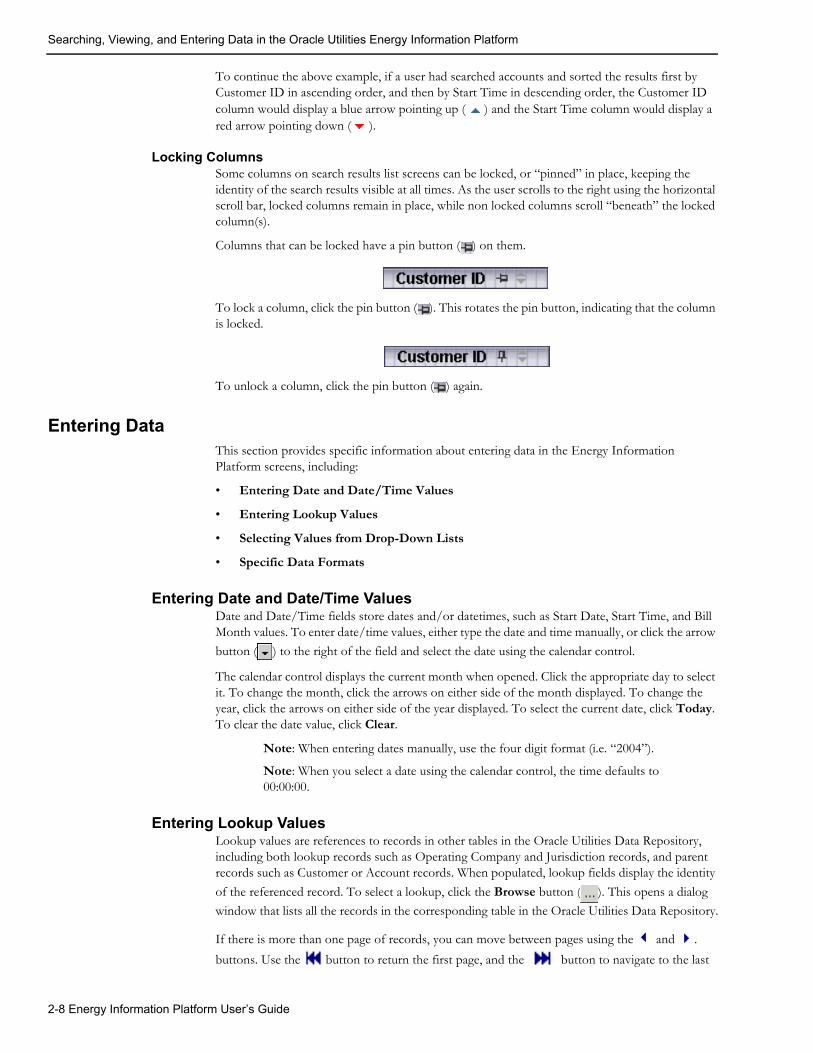
Searching, Viewing, and Entering Data in the Oracle Utilities Energy Information Platform
To continue the above example, if a user had searched accounts and sorted the results first by Customer ID in ascending order, and then by Start Time in descending order, the Customer ID column would display a blue arrow pointing up ( ) and the Start Time column would display a red arrow pointing down ( ).
Locking ColumnsSome columns on search results list screens can be locked, or “pinned” in place, keeping the identity of the search results visible at all times. As the user scrolls to the right using the horizontal scroll bar, locked columns remain in place, while non locked columns scroll “beneath” the locked column(s).
Columns that can be locked have a pin button ( ) on them.
To lock a column, click the pin button ( ). This rotates the pin button, indicating that the column is locked.
To unlock a column, click the pin button ( ) again.
Entering DataThis section provides specific information about entering data in the Energy Information Platform screens, including:
• Entering Date and Date/Time Values
• Entering Lookup Values
• Selecting Values from Drop-Down Lists
• Specific Data Formats
Entering Date and Date/Time ValuesDate and Date/Time fields store dates and/or datetimes, such as Start Date, Start Time, and Bill Month values. To enter date/time values, either type the date and time manually, or click the arrow
button ( ) to the right of the field and select the date using the calendar control.
The calendar control displays the current month when opened. Click the appropriate day to select it. To change the month, click the arrows on either side of the month displayed. To change the year, click the arrows on either side of the year displayed. To select the current date, click Today. To clear the date value, click Clear.
Note: When entering dates manually, use the four digit format (i.e. “2004”).
Note: When you select a date using the calendar control, the time defaults to 00:00:00.
Entering Lookup ValuesLookup values are references to records in other tables in the Oracle Utilities Data Repository, including both lookup records such as Operating Company and Jurisdiction records, and parent records such as Customer or Account records. When populated, lookup fields display the identity
of the referenced record. To select a lookup, click the Browse button ( ). This opens a dialog
window that lists all the records in the corresponding table in the Oracle Utilities Data Repository.
If there is more than one page of records, you can move between pages using the and .
buttons. Use the button to return the first page, and the button to navigate to the last
2-8 Energy Information Platform User’s Guide

Searching, Viewing, and Entering Data in the Oracle Utilities Energy Information Platform
page. To change the number of results that appears on each page, enter the number in the Rows field and press the Enter key.
To search for a specific record, click Search. The dialog displays a search screen.
Enter the appropriate parameters for your search and click Search. The dialog will display a list of records that match the search criteria.
Click the [...] link to select the appropriate record. The lookup field is automatically populated.
Selecting Values from Drop-Down ListsDrop-down lists allow users to select a value from a pre-populated list, and can contain either pre-set values or values from tables in the Oracle Utilities Data Repository.
To select a value from a drop-down list, click the arrow next to the field. This opens a lists that includes all the values available.
If one or more of the values is longer than the default size of the list, click the lower right corner of the list and resize the list as necessary.
Specific Data FormatsSome fields on some screens of the Energy Information Platform require that data be entered in a specific format. This most often applies to currency and date fields, but can also apply to other number fields and other types of data. Moving the mouse pointer over the icon displays a tooltip that contains the correct format for the field.
If data is entered in an incorrect format, the border of the field turns red indicating that there is an error in the data in the field. Moving the mouse pointer over the field displays a tooltip that describes the correct format for the field.
Required FieldsFields that are required are indicated by an asterisk (*).
Currency FieldsCurrency fields are indicated by a currency symbol to the left of the field.
Working with the Oracle Utilities Energy Information Platform 2-9

Searching, Viewing, and Entering Data in the Oracle Utilities Energy Information Platform
2-10 Energy Information Platform User’s Guide

Chapter 3User Settings
This chapter describes the Energy Information Platform dashboard, user preferences, online help, and other options, including:
• Dashboard
• Set Preferences
• Online Help
• Options
• General Options
• Billing Options
• Report Options
User Settings 3-1

Dashboard
DashboardWhen a user first logs on to the Oracle Utilities Energy Information Platform, a customizable dashboard is displayed in the Main Workspace. The Energy Information Platform dashboard displays a user-defined set of windows (known as “clips” ) that can display information related to specific Oracle Utilities processes, or other information.
This section describes how users define the look and content of the dashboard, including:
• Working with the Dashboard
• Dashboard Clips
Working with the DashboardYou can change the theme (the “skin” displayed on the Energy Information Platform) as well as the content of the dashboard. The dashboard displays two tabs, the Browse tab, used when viewing clips, and the Catalog tab, used to specify the content and layout of the dashboard.
How to set the theme of the Energy Information Platform and dashboard:
1. Click the Change Theme icon on the Left menu. The Change Theme dialog opens.
2. Select the desired theme on the Theme tab.
3. Select the desired color scheme on the Color tab (optional).
4. Click Apply. The color and theme of the Energy Information Platform, including the dashboard change to the selected theme/color. To close the Change Theme dialog without changing the theme, click Cancel.
How to specify the content of the dashboard:
1. Click the Catalog tab on the dashboard. The Catalog screen opens.
The top of the Catalog screen displays the currently selected clips. The dashboard screen contains 2 columns, referred to as “Zones.” The left column is Zone 1, the right column is Zone 2.
The bottom of the Catalog screen displays the Catalog Part pane, which you use to select clips to display on the dashboad.
2. Select the clips you want to add to the dashboard in the Catalog Part pane.
3. Select the zone in which you want the selected clips to appear from the Add to drop-down list, and click Add.
The selected clips appear in the selected zone on the dashboard.
4. Repeat steps 2 and 3 for each clip you wish to add to the dashboard.
5. To delete a clip from the dashboard, click the down arrow in the top right corner of the clip you wish to delete, and select Delete.
6. To return to the dashboard and save your changes, click the Browse tab.
How to change the layout of the dashboard:
1. Click the Catalog tab. The Catalog screen opens.
2. Move the individual clips between zones by dragging and dropping the clip you wish to move.
To move a clip in this manner, position the cursor over the title bar of the clip you wish to move, click the right mouse button, and drap the clip towards its desired location. A grey line indicates the position the clip will move to when you release the mouse button.
When the clip is in the desired location, release the mouse button. The clip is now located in that position.
3-2 Energy Information Platform User’s Guide

Dashboard
3. To return to the dashboard and save your changes, click the Browse tab.
Dashboard ClipsThis section describes some of the clips available with the Energy Information Platform dashboard.
Dashboard Clip OptionsEach dashboard clip provides a set of options for how the clip is displayed, including options to
• Minimize/ Restore Clips
• Close Clips
• Edit Clip Content
These options are accessed via icons in the upper right corner of each clip.
Minimize/ Restore ClipsThis option allows users to minimize the clip content and display only the title bar.
To minimize a clip, click the down arrow in the top right corner of the clip you wish to minimize, and select Minimize. To restore the clip, click the down arrow in the top right corner of the clip and select Restore.
Close ClipsThis option allows users to remove a clip from the dashboard.To remove a clip, click the down arrow in the top right corner of the clip you wish to remove, and select Close. To restore a removed clip to the dashboard, click the Catalog tab on the dashboard. See How to specify the content of the dashboard: for more information.
Edit Clip ContentThis option allows users to edit the contents of a clip. When the user selects this option, a screen opens that allows the user to specify the content of the clip. To edit a clip’s content, click Edit and make the appropriate changes on the screen that opens. See Pre-Defined Clips for more information about editing specific clips.
Note: The Edit option is not available on all clips.
Pre-Defined ClipsThe Oracle Utilities Energy Information Platform includes the following pre-defined clips. Individual Oracle Utilities products (such as the Oracle Utilities Load Profiling and Settlement) also include product-specific clips.
Account ClipsThe Energy Information Platform includes the following account-related pre-defined clips:
Favorite Accounts: Lists up to 10 selected accounts. This allows the user to quickly view an account.
To view one of the accounts listed on the clip, click the Account ID.
How to set the contents of the Accounts clip:
1. Click Edit on the Favorite Accounts clip. The Favorite Accounts screen opens.
2. For each account (up to 10) that you wish to display on the clip, click the Browse button
( ). The Accounts dialog opens, listing all the accounts in the Oracle Utilities Data Repository.
If there is more than one page of records, you can move to a specific page of results by clicking the page number at the bottom of the dialog.
User Settings 3-3

Dashboard
To search for a specific record, click Search. The Accounts dialog displays a search screen.
Enter the appropriate parameters for your search and click Search. The Accounts dialog will display a list of account records that match the search criteria.
3. To select an account, click Select. The selected account appears on the Favorite Accounts screen.
4. Repeat steps 2 and 3 for each account you wish to add to the Accounts clip.
5. To remove an account from the Favorite Accounts screen, click the Select button ( ) and click Clear on the Accounts dialog.
6. When you’re finished adding or removing accounts, click Save. The selected accounts will appear on the Accounts clip on the dashboard. To return to the dashboard without saving your changes, click Cancel.
Current Messages: Lists current messages from the Splash Message table in the Oracle Utilities Data Repository.
Work Queues ClipsThe Energy Information Platform includes the following work queue-related pre-defined clips:
Work Queues: Displays the number of open work queue items and work queue approvals assigned to the current user.
Work Queue Type Code: Displays a graph showing the number of open work queue items by work queue type code
Work Queue Assigned Load: Displays a graph showing the number of assigned work queue items to each user.
Work Queue Unassigned: Displays a graph showing the number of unassigned work queue items based on user-defined groupings (known as buckets).
How to set the content of the Work Queue Unassigned clip:
1. Click Edit on the Work Queue Unassigned clip. The Edit Work Queue Buckets screen opens.
2. Define the range for each “bucket” (in terms of number of days) by enter the appropriate numbers in the “From” and “To” columns for each. You can define up to five (5) buckets. For example, to set the first bucket to include those unassigned items that are up to 5 days old, you would enter 0 (zero) in the “From” column and 5 (five) in the “To” column on the first line.
3. Click Save to save your settings. The data on the Work Queue Unassigned clip will be based on the buckets you defined. To return to the dashboard without saving your changes, click Cancel.
Other ClipsThe Energy Information Platform includes the following additional pre-defined clips:
Server Time: Displays the current date and time on the web server. To automatically refresh the content, check the Auto Refresh checkbox. To manually update the date/time, click Get Date.
Quote of the Day: Displays an informative or inspiting quote.
Adapter File Loading Statistics: Displays statistics related to files and payloads processed by the Energy Information Platform Adapter.
To filter the data displayed based on a time frame, selected the desired time frame from the Select Time Frame drop-down list
For each process listed, this clip displays the following:
• Process Source: The name of the Runtime Service which processed the file or payload.
3-4 Energy Information Platform User’s Guide

Dashboard
• Total Files: The total number of files processed.
• File Status: The status (Complete, Error, or Processing) of the file or payload, including:
• Subtotal: The number of records of the displayed status
• Percentage: The percent of records for the displayed status
• Description: A description of the status
MDM Process Control Interface: Displays statistics related to usage import processes performed by Oracle Utilities Meter Data Management. Available with Oracle Utilities Meter Data Management only.
For each process listed, this clip displays the following:
• Source: The name of the Runtime Service which processed the file or payload.
• Transactions per Minute: The number of transactions processed per minute
• Transactions: Details concerning the number of transactions processed, including:
• Total: The total number of transactions processed. A number in red indicates a discrepancy between the total number of transactions stored in the Inbound table (one per process), and the sum of the transactions in the children Inbound Transaction records.
• Rejected: The number of rejected transactions
• Loaded: The number of transactions successfully loaded
• % Loaded: The percentage of transactions that were successfully loaded
To view statistics for a specific process on the Process Control Interface, click the Source.
To filter the data displayed based on a time frame, selected the desired time frame from the Select Time Frame drop-down list. Options include:
• Today Only (default): Displays results as of midnight on the current day.
• Previous Day: Displays results since midnight on the previous day.
• Last 7 Days: Displays results since midnight seven days minus the current day.
• Current Month: Displays results for the time period beginning at midnight on the first day of the current month.
• Previous Month: Displays results for the previous month. The start time for the month is midnight of the first day of the previous month, and the stop time is 23:59:59 of the last day of the previous month.
Settlement: displays links to the settlement and aggregation results for the most recent settlement performed by Oracle Utilities Load Profiling and Settlement. Available with Oracle Utilities Load Profiling and Settlement only.
Clicking on the Settlements link opens the Settlement List screen.
Clicking the Aggregations link opens the Settlement Aggregation Results screen.
Custom ClipsIn addition to the pre-defined clips supplied by Oracle, custom clip libraries and clips can be developed and added to the dashboard.
User Settings 3-5

Set Preferences
Set Preferences
The Set Preferences option (accessed by clicking the Current Data Base icon at the bttom of
the Left menu) allows users to specify user-defined settings used when working with Oracle Utilities applications, including:
• Data Sources
• User Context
• Profiles
• Locales
• Reset Password
Data SourcesThe Data Source tab allows users to switch between data sources while logged into the Energy Information Platform. The data sources available are those associated with the user via the Users Security function.
Note: New users must set their data source the first time they logon.
How to change Data Sources:
1. Click the Current Data Base icon on the Left menu. The Set Preferences screen opens.
2. Select the Data Sources tab (if not currently selected). The Data Sources screen opens.
3. Select the new data source from the ‘New:’ drop-down list and click Set Data Source.
User ContextThe User Context tab allows users to apply user-specific configuration parameters to applications in the Oracle Utilities. These are the same parameters found in the LODESTAR.CFG file. See Oracle Utilities Application Configuration and Command Line Parameters for more information.
How to set user configuration settings:
1. Click the Current Data Base icon on the Left menu. The Set Preferences screen opens.
2. Select the User Context tab. The User Context screen opens. The first time you open this screen, it opens blank.
3. Type in the configuration parameters as appropriate. You can also paste text from existing *.CFG files into this window.
4. Click Save to save your settings. To clear the window, click Refresh.
How to edit user configuration settings:
1. Click the Current Data Base icon on the Left menu. The Set Preferences screen opens.
2. Select the User Context tab. The User Context screen opens, displaying your current settings.
3. Edit your configuration parameters as appropriate. You can also paste text from existing *.CFG files into this window.
4. Click Save to save your settings. To restore your settings to the previously saved version, click Refresh.
3-6 Energy Information Platform User’s Guide

Set Preferences
ProfilesThe Profiles tab allows users to switch between user profiles while logged into the Energy Information Platform. The profiles available are those associated with the user via the Users Security function.
How to change Profiles:
1. Click the Current Data Base icon on the Left menu. The Set Preferences screen opens.
2. Select the Profiles tab. The Profiles screen opens.
3. Select the new profile from the ‘New:’ drop-down list and click Set Profile.
LocalesThe Locales tab allows users to switch between locales and languages while logged into the Energy Information Platform. Locales are used to define regional settings such as number and currency formats when using Oracle Utilities applications in nations outside the United States. Selecting a language causes the text on the application to appear in the selected language. The locales available are those defined in the LOCALES.CFG.XML configuration file. See Chapter Six: Configuration Files in the Oracle Utilities Energy Information Platform Installation and Configuration Guide for more information.
Note: The default locale for new users is None. Users who require a specific locale must set it the first time they logon.
How to change Locales and/or Languages:
1. Click the Current Data Base icon on the Left menu. The Set Preferences screen opens.
2. Select the Locales tab. The Locales screen opens.
3. Select the locale from the Locale drop-down list and the language from the Set Language drop-down list and click Set Locale.
Reset PasswordThe Reset Password tab allows users to change the password they use when logging in to the Oracle Utilities Energy Information Platform.
Note: This option is not available when running Security in LDAP mode.
How to change your password:
1. Click the Current Data Base icon on the Left menu. The Set Preferences screen opens.
2. Select the Reset Password tab. The Reset Password screen opens.
3. Enter the new password in the Password field. By default, passwords can be from 1 to 64 characters in length, can include upper and lower case letters as well as numbers, and are case-sensitive. For example, there is a difference between “Password” and “password”. Password-related requirements can override these defaults. See your system administrator for more information.
4. Enter the new password again in the Confirm Password field.
5. Click the Save link to save the new password. To close the screen without changing the password, click Cancel.
The next time you login, your new password will be in effect.
User Settings 3-7

Online Help
Online Help
The Online Help option opens online help for the Energy Information Platform. The online help
appears in a new browser window, allowing users to switch back and forth between the application and help.
How to open online help:
1. Select Help-›Contents and Index in the Top menu. The online help opens in a new browser window.
2. Locate the topic you need help about via the Contents tab, Index tab, or Search tab.
• The Contents tab allows users to expand/collapse sections of the table of contents as
needed to find a particular topic. Click on the book icons ( and ) to open/close
headings. Click on the topic icon ( )to open it.
• The Index tab allows the user to browse an index for the online help. Click on the index entry for the topic to open it.
• The Search tab allows the user to search the online help for specific words. Enter the word(s) for the search in the text box and click Go! The search results appear beneath the text box. Click on the topic to open it.
3. The selected topic will appear in the right pane of the online help window.
Help IconsA number of icons appear along the top of the online help window. These icons are used for navigating the online help and other functions.These icons perform the following functions:
Icon Description
Show Navigation: Open the navigation frame. Used after opening a single help topic.
Previous: Display the previous help topic.
Next: Display the next help topic.
Show in Contents: Expand the Contents tab to display the current topic.
Print: Print the current topic.
3-8 Energy Information Platform User’s Guide

Online Help
Context-Sensitive HelpUsers can also get online help based on a specific function or screen. This is referred to as context-sensitive help.
How to open context-sensitive help:
1. Open the function or screen you wish to find help about.
2. Select Help-›Contents and Index in the Top menu.
3. An online help window opens displaying the corresponding topic.
4. Optional. Open the navigation frame by clicking the “Show Navigation” icon ( ).
User Settings 3-9

Options
OptionsThis section describes how to set different types of options for use with the Oracle Utilities Energy Information Platform, including:
• General Options
• Billing Options
• Report Options
General OptionsThe General Options feature allows you to set your own default values for several frequently used parameters. These defaults are stored in the Oracle Utilities Data Repository. Whenever you start an application from the Energy Information Platform, these values are automatically supplied—saving you the time and effort of defining them each and every time.
Available General Options include:
• Scope Options
• Report Formatting Options
• Interval Data Options
• Error Handling Options
• User Files Options
• Rate Analysis Options
How to set general options:
1. Select Tools and Utilities-›Options-›General Options.
General options can be viewed and saved at two different levels:
• Default: Settings used as default settings unless specifically overridden for a Session.
• Session: Settings used for the current user session.
2. Select the level you wish to view and/or edit from the View drop-down list.
3. Set your options on each tab as desired.
4. To set the current settings as the settings for the DEFAULTUSER (the default settings for all new users), check the Set DEFAULTUSER Options checkbox.
5. When you have completed the tabs as desired, select the level at which you wish to save your settings from the Save as drop-down list and click Save. To reset the values to the previously saved settings, click Reset.
The next several pages contain detailed information about the General Options tabs.
Scope OptionsThe Scope tab specifies a number of default values used by the system.
Operating Company: The default operating company used when searching accounts.
Jurisdiction: The default jurisdiction used when searching accounts.
Account ID: The default account ID for bill calculations and rate analyses.
3-10 Energy Information Platform User’s Guide

Options
Report Formatting OptionsThe Report Formatting tab specifies formatting preferences used by the system.
Printer:
Default to landscape printing after this many characters: If a single line in a report contains this many characters, the report will default to landscape printing. The default setting is 133 characters.
Minimum printed line width: The minimum number of characters to be presented on a single line. The default setting is 80 characters.
Decimal Places:
Round Revenue ID to X: Specifies the precision of revenue values in reports. This setting affects only values that have been assigned to revenue identifiers via an Assignment, All, or Block statement in the applicable rate form. A value of 0 (zero) means don’t round, -1 means round to dollars, -2 means round to tens of dollars, 1 to tens of cents, 2 to cents, and so on. The default setting is 0.
Display Currency to X: Specifies the number of decimal places shown in reports for dollar values. It is usually set to be consistent with your choice for Round Revenue. A value of 0 (zero) means use the default (display cents), 1 means display tens of cents, 2 means display cents, 3 means display tenths of cents, 4 means display hundredths of cents, and so on. The default setting is 2.
Display Billing Units to X: Specifies the number of decimal places shown in reports for billing unit values.
Display Format:
Display calculation time/date on each page: The date is displayed on every page of every report. If this option is checked, the time is also displayed with the date.
Display midnight as 00:00:00 rather than blank: Specifies whether or not a value (00:00:00) is displayed and printed when the time is midnight.
Interval Data OptionsThe Interval Data tab specifies the source of interval data used by the system, and how interval data is loaded and processed by the system.
Source:
File: Specify a Btrieve file with a fully justified path. The Browse button below becomes active when this option is selected. This is the default setting.
Default: Specifies that the default Interval Data Database identified in the LODESTAR.CFG file be used. See the Oracle Utilities Energy Information Platform Configuration Guide for more information about setting a default Interval Data Database.
Customer Database: Specifies that interval data stored in the Oracle Utilities Data Repository be used. When this button is selected, a drop-down list appears listing all available interval data header tables. The default table is the Channel Cut Header (LSCHANNELCUTHEADER) table. This the default setting.
Export:
Records Overwritten by SAVE to File: This option saves interval data cuts to an export file before they are overwritten by new cuts created by a Rules Language SAVE Statement. The full path and name of the file (including a valid extension) must be specified. This option appends new cuts to the same file without overwriting previously exported cuts.
Intervals:
User Settings 3-11

Options
Exclude intervals with quality less than: Specify a quality level that the interval data must meet or exceed in order to be included in calculations. All interval values with a code less than your selection will be ignored by the applications.
The meaning of the codes is utility-specific. If your utility uses the Oracle Utilities Load Analysis, the quality is expressed using the Oracle Utilities Load Analysis status codes shown below (Oracle Utilities Load Analysis automatically attaches one of these codes to each interval in a cut). The codes are listed in order of decreasing quality—alpha codes generally indicate that the data is acceptable; numeric codes indicate that the data is suspect and should be corrected. Along with the Oracle Utilities Load Analysis codes, your facility may add its own codes.
Use in all day calculations: Check this box if you want the Day Start time to apply to all date calculations that round to a full day or higher.
Day Start: Specify the time that your facility considers the beginning of the day—8:00 am or midnight. This setting pertains to the ROUNDATE Rules Language function.
Display interval end time: Specifies whether the start- or end-times of intervals are displayed for the MAXDATE values in INTDVALUE and INTDTOUVALUE functions. If checked, the end-time is displayed. If unchecked, the start-time is displayed.
Add Fall DST (Daylight Savings Time) value to Energy requests: The Oracle Utilities Data Repository stores energy in a 24-hour format. As such, the system must compensate for the extra hour of interval data that is left over on the day in October when the clocks are turned back for Daylight Savings Time. To do this, the system automatically takes each account’s interval data values for the two 2:00 a.m. hours and averages them together for a single hour. This option enables you to specify how applications handle the “leftover” hour
Status Code Classification of interval data
(blank) Normal
A Normal, alternate-recorded (e.g., hand-entered)
J Data inserted by Oracle Utilities Load Analysis to correct outage
L Default for data modified by Oracle Utilities Load Analysis Load Data Editor
M Splice peak interval (estimated value)
N Interruptible or curtailable load
P Inserted outage
Q Corrected outage
X Cuts resulting from merging invalid data or from unrecognized status codes
Y Reserved
1 Uncorrected outage
2 Non-normal (usually timing-pulse defects)
5 Aggregated interval used in rolling format with partially missing or unavailable data
7 Merged, aggregated, or transformed interval with partially missing data
9 Missing
3-12 Energy Information Platform User’s Guide

Options
when calculating energy from interval data. If this option is checked, the system doubles the averaged value. If the option is unchecked, it uses just the single, averaged value.
User Settings 3-13

Options
Error Handling OptionsThe Error Handling tab specifies how errors are handled by the system.
Upon Rules Language Interval Data Error:
• Stop: Stop processing bill in any billing mode.
• Log Message: Complete processing of bill; include warning message in error log, but not in bill report.
• Continue: Complete processing of bill; do not issue any messages.
• Issue Warning Message: In the Automatic Billing mode, stop processing the bill. In the Automatic or Approval Required modes, complete processing, but issue a warning message in the bill report.
• Issue Information Message: Complete processing of bill; include informational message in bill report.
Info Errors:
Display error messages: If checked, the program will display the number of errors (if any) it encountered during the job run.
Stop analysis after ## errors: The number of errors to allow when running an analysis or bill.
User Files OptionsThe User Files tab specifies where files created by the user are stored by the system.
Default User Directory: If there is a value in this field it will override the USERDIR setting in the configuration file (after the database is opened). Files put in the user directory before the database is opened - such as .log files - will still be placed in the USERDIR directory.
Use last path as default in next browse: If this checkbox is checked, the path used in the last open or save operation will be the default path for the next open and save operation. When the application starts it uses the Default User Directory/USERDIR path in the first open or save.
Rate Analysis OptionsThe Rate Analysis tab specifies default values for processing rate schedules.
Default:
Rate Schedule: The default rate schedule for calculations.
Season Schedule: The default season schedule for calculations.
Note: If when running an analysis or calculation, the input rate form includes a statement that assigns a value to the SEASON_SCHEDULE_NAME identifier, the value in the rate form takes precedence over the Options selection.
Analysis:
Test Period: Can be any period, one month or greater.
3-14 Energy Information Platform User’s Guide

Options
Billing OptionsBilling Options allow users to specify default global options that apply to all accounts in the system. These options apply to all billing types (Approval Required, Automatic Billing, etc.) and to all Oracle Utilities Billing Component users, unlike the user-specific General Options. However, you can override any of these settings for specific rate schedules, rate codes, or accounts in the Oracle Utilities Data Repository.
Available Billing Options include:
• Billing Options
• Billing Rules
• Report Options
• Summary Options
• Multiple Bill History Records
• Check Options
Note: Some tabs and/or options are only available if Oracle Utilities Billing Component is installed on the web server. If a tab/ option is not available, it is not displayed or greyed out.
How to set and save billing options:
1. Select Tools and Utilities-›Options-›Billing Options.
The Billing Options screen appears.
2. Set options as appropriate on the Billing Options, Billing Rules, Report Options, Summary Options, Multiple Bill History Records, and Check Options tabs.
3. To set the current settings as the settings for the DEFAULTUSER (the default settings for all new users), check the Set DEFAULTUSER Options checkbox.
4. Click Save to save the changes. To reset the options, click Reset.
Billing OptionsThe Billing Options tab is used to define global defaults that apply to all accounts for all users.
Default Billing ModeThe Default Billing Mode specifies the mode that Oracle Utilities Billing Component applies to accounts that have not otherwise been assigned a billing mode. If you select Automatic Billing, Oracle Utilities Billing Component calculates the bills, updates the Oracle Utilities Data Repository, and issues transaction records—all without review and approval by a user. If you select Approval Required, Oracle Utilities Billing Component puts the results of its bill calculations in a bill report which you must approve before the software issues any transaction records or updates the bill history record in the Oracle Utilities Data Repository.
Note: Any billing mode flags set for individual rate schedules, rate codes, or accounts in the Oracle Utilities Data Repository records automatically override this setting.
Default Eligibility Pre- and Post-WindowsPre- and Post-Windows specify the number of days before an account’s scheduled read date (the Pre-Window) and the number of days after an account’s scheduled read date (the Post-Window) that defines the “eligibility” window. You can supply any value from 0 to 28 for either. In the Automatic Billing and Approval Required modes, Oracle Utilities Billing Component uses this window to identify “eligible” accounts. That is, if today’s date falls within this window, Oracle Utilities Billing Component begins scanning for the data required to bill the account and continues scanning until it comes in or the window for the account passes today.
User Settings 3-15

Options
Note: If you set the Post Window to 0, the data must be available by the end of the read date, or it is considered missing. You can override the eligibility window setting for individual accounts and recorder types.
Special Event Pre WindowThe Special Event Pre Window specifies the number of days prior to the billing date within which a Billing Analyst must approve an account’s Special Events information in order for the account to be billed. You can enter any value from 0 to 28.
This feature is designed to ensure that all Special Events are included in a bill. For example, suppose that the Billing Analyst approved an account’s Special Event information on schedule, but for some reason the account’s meter could not be read until seven days after the scheduled date. That would mean there would be seven days during which a Special Event could occur but not be included in the current bill. However, if you set the Special Event Pre Window to some number less than 7, Oracle Utilities Billing Component would flag the account as “ineligible” and the billing analyst would have to update the special events information.
Billing RulesThe Billing Rules tab defines specific rules that are applied to billing.
Effective Date isThe Effective Date is the date used to determine Rate Form versions, factor values, and the default for determining the season. There are five options:
• Bill Stop
• Bill Start
• 1st of Bill Month
• Scheduled Read Date
• Governing Date.
Allow Saves without SAVE TO CIS statementNormally output records are created as part of a bill calculation. These records are used with non-Oracle Utilities Billing Component systems such as printing, accounts receivable, and so on. Oracle Utilities Billing Component verifies that at least one output record has been created before saving any data to the Oracle Utilities Data Repository. Check this box to turn this verification off, allowing you to save to the database without creating an output record.
You must Approve a bill to save it to the Oracle Utilities Data Repository. When you Approve the bill, data is saved and the Bill Time (BILLTIME) column in the Bill History is set.
Retrieve all Account DeterminantsNormally, to improve performance, Oracle Utilities Billing Component loads only the determinants that are explicitly used in the Rate Schedule. However, if your rate schedules use indirect identifiers (the @ operator) to retrieve determinant values you need to turn this option on. Oracle Utilities Billing Component then loads all determinants in the account’s Bill History records.
Report OptionsThe Report Options tab is used to define global defaults for report options. These defaults apply to all reports generated by Oracle Utilities Billing Component. These can be overridden for a single report by selecting Options: Report from the report window. See Report Options on page 3-19 for more information.
3-16 Energy Information Platform User’s Guide

Options
Print DetailThe Print Detail option determines the level of detail included in the bill reports, transaction records, and bill faxes or E-mail. Select one of the following:
• None: Effective revenue only.
• Normal: Effective revenue, plus any charges assigned to a revenue identifier and any values assigned to a Report Statement in the applicable rate form.
• All: Effective revenue, plus revenue identifiers, plus the values associated with the Rules Language Label and Report statements in the rate form.
Show Bill History Problems/Resolutions in Bill ReportsIf checked, this option specifies that any problems or resolutions that a Billing Analyst has entered into the Bill History Problem record for the current bill period appear near the top of the bill report (in the header section, just after the customer and account information). This option applies to all bill reports produced by Oracle Utilities Billing Component.
Summary OptionsThe Summary Options tab is used to define how accounts with multiple rates and customer summary rate schedules are processed.
Compute Multiple Rates per AccountThis option specifies whether all effective rates, or only the most recent rate is used for billing. The options available include:
• No: Oracle Utilities Billing Component calculates each account’s bill using just the most recent rate specified in the Account Rate Code History Table for that account.
• Throughout Bill Period: Compute multiple rates using all rates in effect for that account throughout the Bill Period, as specified in the Account Rate Code History Table. When computing multiple rates, Oracle Utilities Billing Component executes the rates in reverse order starting with the record with the most recent Start Time.
• On Effective Date: Compute multiple rates using all rates in effect for that account on the Effective Date, as specified in the Account Rate Code History Table.
Note: If you use either of the latter two options, be sure that all inactive rate codes have a stop time in the Account Rate Code History Table; otherwise they will be included in the calculations.
Enable Customer SUMMARY Rate SchedulesIf this is checked, Oracle Utilities Billing Component can process Summary rate schedules.
Multiple Bill History RecordsThe Multiple Bill History Records tab is used to define how accounts with multiple Bill History records per bill period are processed.
Allow Multiple Bill History Records per Bill Period/Read DateNormally, Oracle Utilities Billing Component uses the billing cycle’s scheduled meter read dates to match an account’s Bill History records with the correct bill periods. However, this may not suffice in all cases, either because the metered data does not come in from the field on a reliable schedule, or because the metering and billing schedule at your company is more complex. This tab enables you to choose the action that Oracle Utilities Billing Component takes when it encounters two or more account Bill History records associated with the same read date. The option you choose depends upon the metering and billing policies of your company. This setting applies to Automatic Billing, Approval Required, and Current/Final Bill.
User Settings 3-17

Options
• No: Oracle Utilities Billing Component rejects all Bill History records for the specified account that have the same read date. It does not process the bills, and issues an error message instead.
• Bill Individually - Allow Out of Order Bill Periods: This option is designed primarily for situations in which metered data comes in from the field irregularly—for example, readings for bill periods arrive out of sequence, and/or scheduled read dates are missed altogether.
If you select this option, Oracle Utilities Billing Component treats any account Bill History records that have the same read date as valid records, and processes them as separate and complete bills. It retrieves and bills the previously unbilled Bill History records for the account (Bill Time value equals NULL), in sequence, from oldest to most recent. To determine the bill period that the Bill History record actually belongs to, it looks at the Bill History record’s Start Date/Time for the metered data and processes the bill accordingly. If the applicable rate form includes any SAVE statements, the computed values are saved to the Bill History record for the correct bill period.
• Bill Individually - Monthly Merge Historical Values: This option is designed primarily for companies whose bill calculations require determinant values for sub-periods within the current bill period (e.g., weekly kWh), as well as values for entire historical bill periods (e.g., maximum kW for the past 12 bill months). In this case, multiple sub-period records (e.g., records with different start- and stop-dates) may be associated with a single scheduled read date.
If you select this option, Oracle Utilities Billing Component assumes that multiple bill history records with the same read date for one account are in fact sub-period records. To perform the calculations (depending upon the rate schedule), Oracle Utilities Billing Component first aggregates historical sub-period values and start- and stop-dates to find values for entire historical bill periods. It then bills each sub-period for the bill period (same scheduled read date), from oldest through most recent.
Check OptionsThe Check Options tab is used to define how Oracle Utilities Billing Component performs several checks before billing an account. In some billing systems, some of these checks are unnecessary. Use these options to turn off the unneeded checks, to improve performance.
Do not use Interval DataThis option turns off all support for Interval Data during billing.
Do not use Interval Data to Compute Start/StopThis option disables use of interval data cuts to compute the bill start and stop, and do not verify that all the account’s interval data is ready. If neither Interval Data check is turned off and Multiple Bill History Records are allowed, only the verification is performed.
Do not check for Interval Data gapsThis option turns off checking for gaps between cuts. The rate schedule should then check for missing data (status code ‘9’) to validate the data. If this is not checked, a Warning will be reported if there are gaps between the interval data cuts.
Do not check Account NotesThis option disables checks for Account Notes/Work Queue Items that stop billing in Automatic Billing or Approval Required. Do not write Account Notes/Work Queue Items from Automatic Billing or Approval Required.
Do not check Override ReadyThis option disables checks that Special Events or Overrides are Ready.
3-18 Energy Information Platform User’s Guide

Options
Do not check Bill Determinant UseThis option disables checks of the account’s Bill Determinants’ Use.
Do not check Account’s Meter ValuesThis option disables verification that an account’s scalar data is in the Meter Value Table.
Do not check Rate Code FlagsThis option disables use of the BILLINGMODEFLAG, PRINTDETAIL or FULLDAYBILL values in the RATECODE Table. If this is checked, it also turns off the same flags in the Rate Forms (RATEFORM) Table.
Do not check Rate Schedule FlagsThis option disables use of the BILLINGMODEFLAG, PRINTDETAIL or FULLDAYBILL values in the RATEFORM Table, independent of the RATECODE Table.
Use MDM schemaWhen this option is checked, Oracle Utilities Billing Component checks the Oracle Utilities Meter Data Management (Oracle Utilities Meter Data Management) tables, specifically the Meter Data Channel Cut table, for interval data when billing accounts.
Checking this option also automatically checks the following other options:
• Do not check for Interval Data Gaps
• Do not check Account’s Meter Values
It also disables the following options:
• Do not use Interval Data
• Do not use Interval Data to compute Start/Stop
Use earliest unbilled bill historyThis option is used with bill determinant processing performed by Oracle Utilities Meter Data Management. This option works in conjunction with the "Allow Multiple Bill History Records per Bill Period/Read Date" option (see Multiple Bill History Records on page 3-17).
When the "Allow Multiple Bill History Records per Bill Period/Read Date" option is set to "No", this option has the following effect in the bill determinant processing:
• If unchecked (off), the most recent billed history is used to compute the next bill period start and stop dates.
• If checked (on). the earliest unbilled bill history is used; this will allow out-of-order bill history read dates in the recalculation processing but will not affect the initiation of bill determinant calculations.
Report OptionsReport options allow users to customize the contents of a report, including the report presentation, the print detail level, and the problem determination options.
Note: Changes to report options as described in this section apply only to the report currently being run.
Available Report Options include:
• Presentation
• Print Detail
• Problem Determination
• Results Columns
User Settings 3-19

Options
Note: Not all tabs and/or report options are available for all reports. If a tab/ option is not available, it is not displayed or greyed out.
How to set and save report options:
1. Select Tools and Utilities-›Options-›Report Options.
The Report Options screen appears.
2. Make any appropriate changes on the Presentation, Print Detail, Problem Determination, and Results Columns tabs.
3. Click Save to save the changes. To reset the Print Options, click Reset.
3-20 Energy Information Platform User’s Guide

Options
PresentationThe Presentation tab allows users to customize the presentation of a report.
Report TitlesTo add optional titles to a report, enter the title in one of the three optional title fields.
Other OptionsTo disable graphing for the report, check the “Disable graphing of data” checkbox.
To display only summaries for the report, check the “Display summaries only” checkbox.
To keep the report data for CSV/XML exporting, check the “Keep data” checkbox.
Print DetailThe Print Detail tab allow users to specify the level of detail included in both a bill report and transaction record. The information computed and available for reporting is determined by the statements used in the applicable rate form. The Print Detail tab enables you to specify how much of that available data is included in the reports and transaction records.
Print Detail OptionsDefault: This option means the program will use the Print Detail setting normally applied to the account (via the Account, Rate Code, Rate Schedule, or Global options specified). Alternately, you can override the usual setting for just this job by selecting one of the following:
None: This option displays effective revenue only.
Normal Detail: This option displays effective revenue, plus any charges assigned to a revenue identifier and any values assigned to a Report Statement in the applicable rate form.
All Detail: This option displays effective revenue, plus revenue identifiers, plus the values associated with the Rules Language Label and Report statements in the rate form.
The table below details how these options apply to specific components of a report and transaction record.
To override the Print Detail Options setting for specific components of a bill report and transaction record, select the specific options for each component. For each report component type, select one of the following:
• On - Include the component in the report and transaction record.
• Off - Exclude the component from the report and transaction record.
• Print Detail Option - Apply the setting specified under Print Detail Options. The specific manner in which these settings affect individual report components is detailed in the table above. For example, if you had selected “None” under Print Detail Options, and selected Print Detail Option here for Input Values, the input values would not appear in the report.
Following is a brief description of each of the report components.
Report Component None Normal All
Customer/Account Detail X X X
Input Values X X
LABELed Identifier Values X
Simple Report Values X X
Compound Report Values X X
User Settings 3-21

Options
Customer/Account Detail. Date activated, billing mode, number of days specified for the eligibility pre- and post-windows.
Input values. This option reports the parameters specified for the bill calculations: bill start and end date; date that the account's meter was scheduled to be read; rate code applied to the account; number of days in bill period, and the bill month.
LABELed Identifier Values. This option reports the any identifier values and text strings specified using a LABEL Statement in the rate form. LABEL statements are typically used to substitute meaningful labels for bill determinant names or other brief and sometimes-cryptic identifiers (e.g., LABEL LF “LOAD FACTOR” displays LOAD FACTOR and its value in the report). They are often used for column headings or report subtitles.
Note: If a report component type is designated to appear in a report, and it is assigned a name using a LABEL Statement, its values will automatically appear in the report, with the new label. In other words, it is not necessary in that case to apply the LABELed identifier values option to get the label and value to appear. For example, the applicable rate form might have the statement LABEL $EFFECTIVE_REVENUE “Total Charges”. Because Effective Revenue is automatically included in all report types, “Total Charges” will appear, no matter what print details options you choose.
Simple report values. This option reports any values that were assigned to an identifier using a REPORT Statement in the rate form. REPORT statements are typically used to report values of interest that are calculated and/or drawn from the database, such as peak times.
Compound report values. This option reports any values associated with a stem identifier using a REPORT Statement in the rate form.
Problem DeterminationThe Problem Determination tab allows users to specify the level of problem determination detail included in both a bill report and a transaction record.
When problems occur during the processing of a bill, error messages and other information useful in determining the cause of the problem are created. The Problem Determination tab option enables you to specify how much of that data is included in the reports and transaction records.
Problem Determination OptionsShow All Error Messages: This option reports all error messages that occur while processing the bill.
Show All Input Options: This option reports all input options used in processing the bill.
Show Bill records to Save (BillHistory, CSS, etc). This option includes the Bill History records in the Bill Report. It is typically only used for testing. If you turn this option off, the records are still output when you approve a bill, but they are not displayed or printed in the bill report.
Show Rate Schedule Used in Bill Calculation: This option includes the rate schedule used in processing the bill on the bill report.
3-22 Energy Information Platform User’s Guide

Options
Results ColumnsThe Results Columns tab allows users to specify the labels of the Bill Calculation Results section of a bill report.
The Bill Calculation Results section displays the number of billing units, the distribution of those billing units, the charge rate, and revenue for each revenue identifier used in a rate schedule.
Results Columns OptionsTo change one or more of the Bill Calculation labels, check the Show all input options checkbox and edit the labels as appropriate.
To omit one or more of the columns from the bill report (except the Revenue column), check the Change Bill Calculation Label checkbox and delete the appropriate label.
• Billing Units: The label for the Billing Units column. If blank, the column is omitted.
• Distribution: The label for the Distribution column. If blank, the column is omitted.
• Charge Rate: The label for the Charge Rate column. If blank, the column is omitted.
• Revenue: The label for the Revenue column. This column cannot be omitted. If blank, the column label is Revenue.
User Settings 3-23

Options
3-24 Energy Information Platform User’s Guide

Chapter 4Searching and Viewing Customer and Account
Data
The Oracle Utilities Energy Information Platform allows users to search for and view information about selected customers and accounts. This chapter describes how to search and view customer and account data, and includes the following:
• Searching and Adding Customers
• Viewing Customer Data
• Searching Accounts
• Viewing Account Data
Searching and Viewing Customer and Account Data 4-1

Searching and Adding Customers
Searching and Adding CustomersThe Customers option on the Entity Management menu allows users to search for customers in the Oracle Utilities Data Repository based on various search criteria and to add new customers. Once added to the database, Contacts and Accounts can then be associated to the customer.
How to search customers:
1. Select Entity Management-›Customers.
The Customers screen opens.
2. Enter the search criteria in the appropriate field.
You can search based on the Customer Name, Customer ID, or an Account ID associated with the customer. You can also search based on contact information such as phone number, address, city/state, etc.
You can use the percent sign (“%”) as a wildcard character when entering values in any of the fields. For instance, if you want to search for all customers whose name begins with the letter G, you could enter “G%” in the Name field. You can use this wildcard before or after specified letters or numbers (i.e. you would use %t to search for all customers whose names end with the letter t, etc.).
Note that customer Names, IDs, and Account IDs are case-insensitive. For example, there is no difference between the “Cust_1” and “cust_1” customer IDs.
3. Specify how the search results are displayed.
• Select the manner in which the results are sorted by clicking the Sort by plus (“+”) sign. See Specifying How Results are Sorted on page 2-7 for more information.
• Specify how many results should appear on each page in the Page Length field.
4. Click Search to perform the search. To clear all the search fields, click Reset.
5. The search results appear on the Customers screen.
The Search Results window displays the following information for each customer:
• Customer Name
• Customer ID
• Summary Billing Flag
• Contact Information (includes Contact Type, Name, Address, City, and State).
6. To sort the results by one of the columns, click the appropriate arrow on the column heading. For example, to sort the results in ascending order by Customer Name, click the “up” arrow on the Customer Name column heading. See Sorting Search Results on page 2-7 for more information.
If there is more than one page of results, you can move between pages using the and buttons. To change the number of results that appears on each page, enter the number in the Rows field and press the Enter key.
7. To view a customer, click on the Customer ID. Customer data for the selected customer will appear in the Customer screen.
8. To perform another search, click New Search. To refresh the contents of the Customers screen, click the Refresh icon.
4-2 Energy Information Platform User’s Guide

Searching and Adding Customers
How to add a customer:
1. Select Add Customer on the Customers screen. The Add Customer screen opens.
2. Enter the ID and Name for the new customer.
3. Set the Summary Bill flag for the customer using the drop-down list. This flag indicates if Oracle Utilities Billing Component should produce a summary bill for the customer, or bill the customer’s account individually.
4. Select the Directory - Account Manager and Directory - Contact for the customer.
For each of these, click the Browse button ( ). This button opens a dialog window that lists
all the options available for the selected field. Click the [...] next to the appropriate Directory or Contact. The field on the Create Customer window is automatically populated.
5. Select the Account Manager Fax Flag and the Contact Fax Flag for the customer using the drop-down lists. These flags indicate if bills created for this customer should be sent via email or fax.
6. Click Save to save your changes. To close the window without making any changes, click Cancel.
7. The newly created customer appears on the Basics clip of the Customer window.
Note: If you have added custom fields to your Customer table in the Oracle Utilities Data Repository, you may have to enter additional information than that described here.
Searching and Viewing Customer and Account Data 4-3

Viewing Customer Data
Viewing Customer DataCustomer data is viewed from the Customer dashboard. This window opens when you select a Customer ID from the Customer search results screen or other screen.
The Customer dashboard provides access to the following customer-related information:
• Customer Basics
• Customer Contacts
• Customer Accounts
• Customer Contracts (available with Oracle Utilities Billing Component and Oracle Utilities Quotations Management only)
See Working with the Dashboard on page 3-2 for more information about working with the dashboard.
Customer BasicsThe Customer Basics clip on the Customer dashboard displays the Customer ID and Name.
To view basic customer data, click Details. The Customers screen opens.
The Customers screen displays basic information about the customer, including:
• UID: The unique ID of the customer record in the Oracle Utilities Data Repository (read-only)
• ID: The customer ID.
• Name: The name of the customer.
• Summary Bill: A flag that indicates if Oracle Utilities Billing Component should produce a summary bill for the customer, or bill the customer’s account individually.
• Directory - Account Manager: The account manager for the customer, from the Directory table.
• Directory - Contact: The contact for the customer, from the Directory table.
• Account Manager Fax Flag: A flag that indicates if Oracle Utilities Billing Component should send billing results to the Account Manager via email or fax.
• Contact Fax Flag: A flag that indicates if Oracle Utilities Billing Component should send billing results to the Contact via email or fax.
• Credit Score: A score that represents the payment performance history of the customer (used by the Collections Management Extension).
Note: If you have added customized fields to the Customer table in the Oracle Utilities Data Repository, they may also appear on this tab.
• Owner: The user ID of the user who last updated the customer record.
To search for a different customer, click Search. To delete the customer, click Delete. To return to the Customer dashboard, click Customer Summary.
How to edit customer records:
1. Update the Customer ID and Customer Name for the customer as appropriate.
2. Set the Summary Bill flag for the customer using the drop-down list. This flag indicates if Oracle Utilities Billing Component should produce a summary bill for the customer, or bill the customer’s account individually.
4-4 Energy Information Platform User’s Guide

Viewing Customer Data
3. Select the Directory - Account Manager and Directory - Contact by clicking the Browse
button ( ). This button opens a dialog window that lists all the options available for the
selected field. Select the appropriate record. The field is automatically populated.
4. Set the Account Manager Fax Flag and Contact Fax Flag by selecting the appropriate option from the drop-down lists.
5. Optional. Enter a Credit Score for the customer.
6. Click Save to save your changes. To save the updates as a new customer, click Save As New (note that this option is only available if you change the ID field).
How to view Customer related tables:
1. Click Customer Related Tables on the Basics clip. The Customer screen opens, displaying the customer record, but also links to related tables.
To view records in one of the related tables, click the name of the table in the Children section of the screen. A list of records associated with the customer will be displayed. If there is only one record in the selected table, that record will be displayed.
Customer ContactsThe Customer Contacts clip on the Customer dashboard displays the Name, Type, and Details for a number of contacts associated with the customer.
To view a list of all customer contacts, click the number in parentheses. The Contacts screen opens.
The Contacts screen displays the following information about each contact:
• Contact Type: The type of contact (Billing, Legal, etc.).
• Name: The name of the contact.
• Phone: The contact’s phone number.
• Fax: The contact’s FAX number.
• Email: The contact’s email address.
• Address: The contact’s address (street address, City, State, Country, Postal Code).
Additional contact information for each contact can be viewed and/or edited by clicking the [...] link for the contact. Note: The listed contacts come from the Customer Contact table. Those without a [...] link are missing either the Type on the Customer Contact record, or the Address on the related Directory record. You can update these using either the Data Manager application or Data Navigator.
How to edit customer contacts:
1. Click on the [...] link of the contact to edit. The Contact Information window opens.
2. Edit the contact information as appropriate.
3. Click Save to save your changes. To reset the contact information to the previously saved version, click Reset. To close the window without making any changes, click Cancel.
How to remove customer contacts:
1. Check the checkbox for the contact to remove.
2. Click Delete to remove the contact.
How to add an existing contact to a customer:
1. Click the Add Existing link on the Contacts screen. The Contact Search window opens.
2. Enter the search criteria in the appropriate field.
Searching and Viewing Customer and Account Data 4-5

Viewing Customer Data
You can search based on the Type, Company Name, First/Last name, or address, city/state, etc.
You can use the percent sign (“%”) as a wildcard character when entering values in any of the fields. For instance, if you want to search for all contacts whose name begins with the letter G, you could enter “G%” in the Name field. You can use this wildcard before or after specified letters or numbers (i.e. you would use %t to search for all contacts whose names end with the letter t, etc.).
Note that company names are case-insensitive. For example, there is no difference between the “Thomas” and “thomas” names.
3. Click Search to perform the search. To clear all the search fields, click Reset. To close the window without making any changes, click Cancel.
4. The search results appear in the Search Results window.
The Search Results window displays the following information for each customer:
• Contact Type
• Contact Name
• Phone Number, Fax, Email, and Address for the contact
5. To view a contact, click on the [...] link of the contact. Contact data for the selected contact will appear in the Contact Window.
6. To perform another search, click New Search. To refresh the contents of the Search Results window, click Refresh. To close the window, click Cancel.
How to create new customer contacts:
1. Click the Add link on the Contacts window. A blank Contact Information window opens.
2. Enter the contact information as appropriate. Be sure to enter the required fields (Address 1).
3. Click Save to save your changes. To clear all the fields, click Reset. To close the window without making any changes, click Cancel.
4-6 Energy Information Platform User’s Guide

Viewing Customer Data
Customer AccountsThe Customer Accounts clip on the Customer dashboard displays the ID and Name for a number of accounts associated with the customer.
To view a single account of those listed, click the Account ID on the clip. The Account Summary screen opens displaying the selected account. See Viewing Account Data for more information.
To view a list of all accounts associated with the customer, click the number in parentheses. The Accounts screen opens.
The Accounts screen displays a list of accounts associated with the Customer. To view a specific account, click the Account ID. The Account Summary screen opens displaying the selected account. See Viewing Account Data for more information.
How to add an account to a customer:
1. Click Add Account in the upper left corner of the Accounts screen. A blank Accounts screen opens.
2. Enter the ID and Name for the new account.
Enter the Start Time for the account. You can enter the date either by typing the date manually or clicking the drop-down arrow to the right of the date field. This opens a calendar dialog that you can use to select the start date. You can enter the time either by typing the time manually, or by using the default time of 00:00:00. If appropriate, enter a Stop Time for the account in the same manner.
3. Enter an optional Operating Company, Jurisdiction, SIC, Account Status, Revenue Code, Region, and Currency Code for the Account.
For each of these, click the Browse button ( ). This button opens a dialog window that lists
all the options available for the selected field. Click the Code of the appropriate Operating Company, Jurisdiction, SIC, Account Status, Revenue Code, Region, and Currency Code. The fields on the Accounts tab are automatically populated.
4. Select the Billing Mode Flag, Print Detail, Full Day Bill, and EDI flags for the account from the drop-down lists.
5. Set the Prewindow and Postwindow for the account as appropriate.
6. Click Save to save the account. To close the window without making any changes, click Cancel.
Note: If you have added customized fields to the Account table in the Oracle Utilities Data Repository, they may also appear on this tab.
Customer Contracts (available with Oracle Utilities Billing Component and Oracle Utilities Quotations Management only)
The Contracts clip on the Customer dashboard displays the Contract ID, Start Time, Contract Type, and Contract Status for contracts associated with the customer.
To view a single contract of those listed, click the Contract ID on the clip. The Contracts screen opens displaying the selected contract. See the Oracle Utilities Billing Component User’s Guide or Oracle Utilities Quotations Management User’s Guide for more information about viewing contracts.
To view a list of all contracts associated with the customer, click the number in parentheses. The Contract Search Result screen opens.
This screen displays a list of contract associated with the Customer. To view a contract, click the Contract ID. See the Oracle Utilities Billing Component User’s Guide or Oracle Utilities Quotations Management User’s Guide for more information about viewing contracts.
Searching and Viewing Customer and Account Data 4-7

Searching Accounts
Searching AccountsThe Accounts option on the Entity Management menu allows users to search for accounts in the Oracle Utilities Data Repository based on various search criteria.
How to search accounts:
1. Select Entity Management-›Accounts.
The Accounts screen opens.
2. Enter the search criteria in the appropriate field.
You can search based on the Customer Name, Customer ID, or an Account ID associated with the account. You can also search based on Account Status, Operating Company, and/or Jurisdiction. To search on one of these, select it from the drop-down lists. In addition, you can search based on contact information such as phone number, address, city/state, etc.
You can use the percent sign (“%”) as a wildcard character when entering values in any of the fields. For instance, if you want to search for all accounts whose name begins with the letter G, you could enter “G%” in the Name field. You can use this wildcard before or after specified letters or numbers (i.e. you would use %t to search for all accounts whose names end with the letter t, etc.).
Note that account Names, Customer IDs, and Account IDs are case-insensitive. For example, there is no difference between the “Acct_1” and “acct_1” account IDs.
3. Specify how the search results are displayed.
• Select the manner in which the results are sorted by clicking the Sort by plus (“+”) sign. See Specifying How Results are Sorted on page 2-7 for more information.
• Specify how many results should appear on each page in the Page Length field.
4. Click Search to perform the search. To clear all the search fields, click Reset.
5. The search results appear on the Accounts screen.
The Accounts window displays the following information for each account:
• Customer ID
• Account ID
• Account Name
• Account Status
• Start Date/Stop Date
• Contact Information (includes Contact Type, Name, Address, City, and State).
6. To sort the results by one of the columns, click the appropriate arrow on the column heading. For example, to sort the results in ascending order by Account Name, click the “up” arrow on the Account Name column heading. See Sorting Search Results on page 2-7 for more information.
If there is more than one page of results, you can move between pages using the and buttons. To change the number of results that appears on each page, enter the number in the Rows field and press the Enter key.
7. To view an account, click on the Account ID. Account data for the selected account will appear in the Account dashboard.
8. To perform another search, click New Search. To refresh the contents of the Accounts screen, click the refresh icon.
4-8 Energy Information Platform User’s Guide

Viewing Account Data
Viewing Account DataAccount data is viewed from the Account dashboard. This window opens when you select an Account ID from the Account search results screen or other screen.
The Account dashboard provides access to the following account-related information:
• Account Basics
• Account Contacts
• Account Reports
• Recorders
• Meters
• Service Points
• Related Accounts
• Account Billing (available with Oracle Utilities Billing Component only)
• Account Contracts (available with Oracle Utilities Billing Component and Oracle Utilities Quotations Management only)
• Financials (available with Oracle Utilities Billing Component only)
• Collections (available with Oracle Utilities Billing Component only)
• Aggregation (available with Oracle Utilities Load Profiling and Settlement only)
• Meter Data Management (available with Oracle Utilities Meter Data Management only)
See Working with the Dashboard on page 3-2 for more information about working with the Energy Information Platform dashboard.
Searching and Viewing Customer and Account Data 4-9

Viewing Account Data
Account BasicsThe Account Basics clip on the Account dashboard displays the Start Date, Customer ID, and Status of the Account.
To view basic account data, click Details. The Accounts screen opens.
The Account displays basic information about the account, including:
• UID: The unique ID of the account.
• Customer: The customer ID.
• Account ID: The account ID.
• Start Time: Start time for the account.
• Stop Time: Stop time for the account. Accounts with a non-Null stop date are no longer active accounts, and cannot be billed.
• Operating Company: Operating company associated with the account.
• Jurisdiction: Jurisdiction associated with the account.
• Name: The name of the account.
• SIC: The Standard Industrial Classification (SIC) code for the account.
• Account Status: The current status of the account.
• Revenue Code: Revenue code for the account.
• Billing Mode: Billing mode for the account. This can be one of the following:
• Use Default: Uses the default billing mode set in Billing Options.
• Fully Automatic: The account is billed using Automatic billing.
• Approval Required: The account is billed using Approval Required billing.
• Manual Start: The account is billed using manual (Current/Final) billing.
• Print Detail: Specifies the level of information provided on billing reports and transaction records. This can be one of the following:
• Use Default: Use the print detail specified in either the rate code, rate schedule, or Billing Options (in that order).
• None: Effective revenue only.
• Normal: Effective revenue, other revenue identifiers and REPORT statements in the rate form used to calculate the report.
• All Detail: Effective revenue, other revenue identifiers and LABEL and REPORT statements in the rate form used to calculate the report.
• Full Day Bill: A flag that specifies how the end of a billing period is recorded. This can be one of the following:
• Yes: Use midnight of the last full day of the billing period.
• No: Use the actual read date and time.
• Use Default: Use the flag specified in either the rate code or rate schedule (in that order). If neither is available, use the actual read date and time.
• Pre Window: The number of days prior to the scheduled read date when an account becomes eligible for billing. This can be any value from 0 to 28.
• Post Window: The number of days after the scheduled read date when an account remains eligible for billing. This can be any value from 0 to 28.
4-10 Energy Information Platform User’s Guide

Viewing Account Data
• EDI: A flag that indicates if the account supports EDI format.
• Region: Region for the account.
• LS Currency: The currency code for the account, from the LSCurrency table.
• Owner: The owner of the account.
• LS Account Type: The account type.
• Market Participant ID: ID of the market participant associated with the account.
• Organization: Organization associated with the account.
• Industrial Classification Code: The Industrial Classification code for the account.
• Special Handling Code: Handling code for the account.
To search for a different account, click Search. To delete the account, click Delete. To return to the Account dashboard, click Account Summary.
How to edit an account record:
1. Update the information for the account as appropriate.
Select the appropriate flags for Billing Mode, Full Day Bill, EDI, and Print Detail using the drop-down lists.
Enter the Start Date and Stop Date either by typing the date manually, or by clicking the drop-down arrow to the right of the date field. This opens a calendar dialog that you can use to select the appropriate date. Edit the Start Time and Stop Time by typing the time manually.
Enter the appropriate codes for Operating Company, Jurisdiction, SIC, Account Status,
Revenue, Region, LS Currency, and LS Account Type using the Browse button ( ) next to
them. This button opens a dialog window that lists all the options available for the selected field. Click the [...] link for the appropriate Code. The field is automatically populated.
2. Click Save to save your changes. To save your changes as a new account, click Save New (note that this option is only available if you change the ID field). To close the window without making any changes, click Cancel.
How to view Account related tables:
1. Click Account Related Tables on the Basics clip. The Accounts screen opens, displaying the account record, but also links to related tables.
To view records in one of the related tables, click the name of the table in the Children section of the screen. A list of records associated with the account will be displayed. If there is only one record in the selected table, that record will be displayed.
Account ContactsThe Account Contacts clip on the Account dashboard displays the Name, Type, and Details for a number of contacts associated with the account.
To view a list of all account contacts, click the number in parentheses. The Contacts screen opens.
The Contacts screen displays the following information about each contact:
• Contact Type: The type of contact (Billing, Legal, etc.).
• Name: The name of the contact.
• Phone: The contact’s phone number.
• Fax: The contact’s FAX number.
• Email: The contact’s email address.
• Address: The contact’s address (street address, City, State, Country, Postal Code).
Searching and Viewing Customer and Account Data 4-11

Viewing Account Data
Additional contact information for each contact can be viewed and/or edited by clicking the [...] link for the contact. Note: The listed contacts come from the Account Directory table. Those without a [...] link are missing either the Type on the Account Directory record, or the Address on the related Directory record. You can update these using the Data Manager application or Data Navigator.
How to edit account contacts:
1. Click on the [...] link of the contact to edit. The Contact Information window opens.
2. Edit the contact information as appropriate.
3. Click Save to save your changes. To reset the contact information to the previously saved version, click Reset. To close the window without making any changes, click Cancel.
How to remove account contacts:
1. Check the checkbox of the contact to remove.
2. Click Delete to remove the contact.
How to add an existing contact to an account:
1. Click the Add Existing link on the Contacts screen. The Contact Search window opens.
2. Enter the search criteria in the appropriate field.
You can search based on the Type, Company Name, First/Last name, or address, city/state, etc.
You can use the percent sign (“%”) as a wildcard character when entering values in any of the fields. For instance, if you want to search for all contacts whose name begins with the letter G, you could enter “G%” in the Name field. You can use this wildcard before or after specified letters or numbers (i.e. you would use %t to search for all contacts whose names end with the letter t, etc.).
Note that company names are case-insensitive. For example, there is no difference between the “Thomas” and “thomas” names.
3. Click Search to perform the search. To clear all the search fields, click Reset. To close the window without making any changes, click Cancel.
4. The search results appear in the Search Results window.
The Search Results window displays the following information for each customer:
• Contact Type
• Contact Name
• Phone Number, Fax, Email, and Address for the contact
5. To view a contact, click on the [...] link of the contact. Contact data for the selected contact will appear in the Contact Window.
6. To perform another search, click New Search. To refresh the contents of the Search Results window, click Refresh. To close the window, click Cancel.
How to create new account contacts:
1. Click the Create link on the Contacts window. A blank Contact Information window opens.
2. Enter the contact information as appropriate. Be sure to enter the required field (Address 1).
3. Click Save to save your changes. To clear all the fields, click Reset. To close the window without making any changes, click Cancel.
4-12 Energy Information Platform User’s Guide

Viewing Account Data
Account ReportsThe Account Reports clip on the Account dashboard displays the 5 most recent reports processed for the account.
Reports listed on this clip are from the Account Reports table, and are one of the following:
• Oracle BI Publisher run for the account, where ACCOUNTID is one of the parameters used when running the report.
• Rules Language reports run for the account, where UIDACCOUNT is one of the parameters used when running the report.
• Oracle Utilities Billing Component reports and calculations run for the account, where the report or calculation was run for the current account only. If the report or calculation was run for a list of accounts that includes the current account or for all accounts, it will not appear on this clip.
To view a specific report, click the Report Title. The selected report will open in the appropriate viewer (based on the report Type). To view a list of all reports for the account, click the number in parentheses. The View Reports screen opens, displaying all reports run for the account. See View Reports on page 7-77 for more information about viewing reports.
RecordersThe Recorders clip on the Account dashboard displays the Recorder ID, Channel Number, and Start Time for the first 10 interval data recorders associated with the account.
To view a list of all recorders, click the number in parentheses. The Recorders screen opens.
The Recorders screen displays channel history records associated with the account. Each channel history record listed on the tab includes the same information.
• Recorder ID: The ID of the recorder.
• Channel Number: The channel number.
• Start Time: The start time for the recorder.
• Stop Time: The stop time for the recorder. Recorders with a non-Null stop time earlier than the current date are no longer active.
• Name: The name of the Unit-of-Measure (UOM) measured by the channel.
To view cuts series associated with the channel history record, click the Recorder ID link. The Interval Data Results window opens.
See Viewing and Exporting Interval Data on page 6-5 for more information about viewing recorder data.
MetersThe Meters clip on the Account dashboard displays the Meter ID and Start Time for the first 10 meters associated with the account.
To view a list of all meters associated with the account, click the number in parentheses. The Meters screen opens.
The Meters screen displays meter history records associated with the account. Each meter history record listed on the screen includes the same information.
• Meter ID: The ID for the meter.
• Start Date: The start date and time for the meter.
Searching and Viewing Customer and Account Data 4-13

Viewing Account Data
• Stop Date: The stop date and time for the meter. Meters with a non-Null stop time are no longer active.
• Service Type: The service type associated with the meter (electric, gas, water, etc.)
• Address: The premise associated with the meter.
• Service Plan: The service plan associated with the meter.
• Number of Dials: The number of dials on the meter.
• Meter Multiplier: The meter’s meter multiplier.
• Meter Offset: The meter’s meter offset.
• End Use Code: Code that represents the end use measured by the meter.
How to edit meter history records:
1. Click the [...] link for the meter history record you wish to edit. The Edit screen opens displaying the selected record.
2. Update the information for the record as appropriate.
Update the Start Time and Stop Time either by typing the date manually, or by clicking the drop-down arrow to the right of the date field. This opens a calendar dialog that you can use to select the appropriate date. Update the time for both the Start Time and Stop Time by typing the time manually.
Some fields have a Browse button ( ) next to them. This button opens a dialog window
that lists all the options available for the selected field. Click the [...] link for the appropriate Code. The field is automatically populated.
3. Click Save to save your changes. To delete the record, click Delete. To close the window without making any changes, click Cancel.
How to add meter history records:
1. Click Add. A blank record opens on the Meters tab.
2. Enter the information for the record as appropriate. Be sure to fill the required fields (Meter ID and Start Time).
Select the Start Time either by typing the date manually, or by clicking the drop-down arrow to the right of the date field. This opens a calendar dialog that you can use to select the appropriate date. Enter the time by typing the time manually.
Some fields have a Browse button ( ) next to them. This button opens a dialog window
that lists all the options available for the selected field. Click the [...] link for the appropriate Code. The field is automatically populated.
3. Click Save to save your changes. To clear all the fields, click Reset. To close the window without making any changes, click Cancel.
4. To view meter reads for a meter, click the <...> link. The Meters screen opens, displaying a list of meter reads. See Viewing Meter Data on page 6-17 for more information.
Service PointsThe Service Points clip on the Account dashboard displays the number of service points associated with the account.
To view a list of all related service points, click the number in parentheses. The Service Points screen opens.
The Service Points screen displays service points associated with the account. Each record listed includes the same information.
4-14 Energy Information Platform User’s Guide

Viewing Account Data
• Service Point ID: The ID of the service point.
• Service Point Name: The name of the service point.
• Account ID: The Account ID related to the service point.
• Market Participant Name: The name of the market participant related to the service point.
• Market Participant ID: The ID of the market participant related to the service point.
• Market ID: The market ID of the market in which the service point is located.
• Invoice ID: Invoice ID related to the service point.
• Recorder ID: Recorder ID for the interval data recorder related to the service point. If more than one record is associated with the service point, this column is blank.
• Meter ID: Meter ID for the meter related to the service point. If more than one meter is associated with the service point, this column is blank.
• Address: Address of the service point.
To view the service point associated with the account, click the Service Point ID link. See Viewing Market Participant Data on page 5-4 for more information about viewing service point data.
Related AccountsThe Related Accounts clip on the Account dashboard displays the Account ID and Name for the current account and the first four accounts related to the current account.
To view the Related Accounts screen, click the number in parentheses.
The Related Accounts screen displays a tree diagram that illustrates the relationship between the current and any related accounts. The Account ID and Account Name are displayed for each related account:
The Related Accounts screen is read-only.
How to view a related account:
1. Click the Account ID link of the related account you wish to view.
2. The selected account appears on the Account dashboard.
Searching and Viewing Customer and Account Data 4-15

Viewing Account Data
Account Billing (available with Oracle Utilities Billing Component only)
The Account Billing clip on the Account dashboard displays the Bill Month, Start time, and Stop Time for the five earliest bill periods associated with the account. If there are more than five billing periods for the account, the number of pages (each comprising five records) appears at the bottom of the clip. To view the 2nd (or other page), click the page number.
To view more detailed billing data, click the number in parentheses. The Billing screen opens, displaying billing data for the most recent bill period. To view a specific billing period, click the Bill Month link for billing period you wish to view. The Billing screen opens for the selected billing period.
The Billing screen allows users to view Bill History, Bill History Value, Override History records, and financial transactions for the account. The Billing screen displays the following information for each bill period:
• Bill Period: A drop-down list containing all bill periods for the account. To change the record being displayed, select the bill period from the drop-down list.
• Start Time: Start time for the bill period.
• Stop Time: Stop time for the bill period.
• Bill Month: The bill month for the bill period.
• Bill Time: The time at which the account was billed for this bill period.
• Read Date: The date of the meter read for the bill period.
• User Specified Stop: A flag that indicates if the stop time for the bill period is user-specified or calculated.
• Billing Code: Billing code associated with this account for this bill period.
• KWH: The energy usage, in kilowatt hours, for the bill period.
• Bill Determinants: A list of Bill Determinants (Bill History Value records) for the selected bill period. You can choose to display either Bill Determinants (Bill History Value records) or Special Events (Account Override History records). When the Bill View tab opens, it initially displays Bill Determinants.
• Special Events: A list of Special Events (Override History records) for the selected bill period. To view all Override History records for the account, check the Show All Records checkbox.
• Transactions: A list of financial transactions (Transaction records) for the selected bill period.
How to edit a bill period:
1. Select the bill period to edit from the Bill Period drop-down list. The selected bill period (and related Bill Determinants and Special Events) will display on the Billing screen.
2. Click the Edit link. The edit screen opens displaying the selected bill period.
3. Update the Start Time, Stop Time, Bill Month, Bill Time, and Read Date either by typing the date manually, or by clicking the drop-down arrow to the right of the date field. This opens a calendar dialog that you can use to select the appropriate date. Update the time for the Start Time, Stop Time, and Bill Time by typing the time manually.
4. Select the User Specified Stop flag from the drop-down list.
5. Update the KWH value as appropriate.
6. Update the (optional) Bill Code by clicking the Browse button ( ). This button opens a
dialog window that lists all the Bill Codes available. Click the [...] link for the appropriate Bill Code. The field is automatically populated.
4-16 Energy Information Platform User’s Guide

Viewing Account Data
7. Select the Profile Status flag from the drop-down list.
8. Click Save to save your changes. To delete the record, click Delete. To close the window without making any changes, click Cancel.
How to add a bill period:
1. Click the Add link. A blank screen opens.
2. Enter the Start Time, Stop Time, Bill Month, Bill Time, and Read Date either by typing the date manually, or by clicking the drop-down arrow to the right of the date field. This opens a calendar dialog that you can use to select the appropriate date. Update the time for the Start Time, Stop Time, and Bill Time by typing the time manually.
3. Select the User Specified Stop flag from the drop-down list.
4. Enter the KWH value as appropriate.
5. Enter the (optional) Bill Code by clicking the Browse button ( ). This button opens a
dialog window that lists all the Bill Codes available. Click the [...] link for the appropriate Bill Code. The field is automatically populated.
6. Select the Profile Status flag from the drop-down list.
7. Click Save to save your changes. To close the window without making any changes, click Cancel.
How to edit Bill Determinants (Bill History Value records):
1. Click the [...] link for the record you wish to edit in the Bill Determinants section. The edit screen opens displaying the selected record.
2. Select the Bill Determinant by clicking the Browse button ( ). This button opens a dialog
window that lists all the Bill Determinants available. Click the [...] link for the appropriate Bill Determinant. The field is automatically populated.
3. Update the Value field for the record as appropriate.
4. Click Save to save your changes. To delete the record, click Delete. To close the window without making any changes, click Cancel.
How to add Bill Determinants (Bill History Value records):
1. Click the Add link. A blank record opens.
2. Select the Bill Determinant by clicking the Browse button ( ). This button opens a dialog
window that lists all the Bill Determinants available. Click the [...] link for the appropriate Bill Determinant. The field is automatically populated.
3. Enter the Value in the Value field.
4. Click Save to save your changes. To close the window without making any changes, click Cancel.
How to edit Special Events (Account Override History records):
1. Click the [...] link for the record you wish to edit in the Special Events section. The Edit screen opens displaying the selected record.
2. Select the Override Code by clicking the Browse button ( ). This button opens a dialog
window that lists all the Override codes available. Click the [...] link for the appropriate Override. The field is automatically populated.
3. Update the Start Time and Stop Time either by typing the date manually, or by clicking the drop-down arrow to the right of the date field. This opens a calendar dialog that you can use to select the appropriate date. Update the time for the Start Time and Stop Time by typing the time manually.
Searching and Viewing Customer and Account Data 4-17

Viewing Account Data
4. Update the Value and String Value as appropriate.
5. Click Save to save your changes. To delete the record, click Delete. To close the window without making any changes, click Cancel.
How to add Special Events (Account Override History records):
1. Click the Add link. A blank record opens.
2. Enter the information for the record as appropriate. Be sure to fill the two required fields (Override Code and Start Time).
3. Select the Override Code by clicking the Browse button ( ). This button opens a dialog
window that lists all the Override codes available. Click the [...] link for the appropriate Override. The field is automatically populated.
4. Enter the Start Time and Stop Time either by typing the date manually, or by clicking the drop-down arrow to the right of the date field. This opens a calendar dialog that you can use to select the appropriate date. Update the time for the Start Time and Stop Time by typing the time manually.
5. Enter the Value in the Value field.
6. Enter the String Value in the String Value field.
7. Click Save to save your changes. To close the window without making any changes, click Cancel.
Account Contracts (available with Oracle Utilities Billing Component and Oracle Utilities Quotations Management only)
The Account Contracts clip on the Account dashboard displays the Contract ID, Start Time, Contract Type, and Contract Status for contracts associated with the account.
To view a single contract of those listed, click the Contract ID on the clip. The Contracts screen opens displaying the selected contract. See the Oracle Utilities Billing Component User’s Guide or Oracle Utilities Quotations Management User’s Guide for more information about viewing contracts.
To view a list of all contracts associated with the account, click the number in parentheses. The Contract Search Result screen opens.
This screen displays a list of contracts associated with the account. To view a contract, click the Contract ID. See the Oracle Utilities Billing Component User’s Guide or the Oracle Utilities Quotations Management User’s Guide for more information about viewing contracts.
4-18 Energy Information Platform User’s Guide

Viewing Account Data
Financials (available with Oracle Utilities Billing Component only)
The Financials clip on the Account dashboard displays the account’s Receivable Status, Current Balance, Past Due Balance, and Deferred Balance.
To view more detailed financial data, click Details. The Financials screen opens.
The Financials screen displays financial information about the account on three panes: the Account Balance pane, the Financial Profile pane, and the Detailed View pane.
Note: The information displayed on the Financials screen is View-only. You cannot change, update, delete, or modify this data in any way.
Account Balance PaneThe Account Balance pane contains account balance information about the account, including:
• Receivable Status: the account’s receivable status, including Current, Past Due, Collections, Uncollectible, or Unrefundable
• Current Balance: the account’s current balance
• Past Due Balance: any past due amount
• Deferred Balance: the amount of the variance on the Budget Plan, if any.
Financial Profile PaneThe Financial Profile pane displays records associated with the account in a “tree” format. This includes any service plans, autopayment plans, transactions or other financial records associated with the account.
Each of the sections below the account (such as Service Plans) can be expanded to display specific records by clicking the arrow. To collapse the tree so that fewer levels of detail are shown, click the arrow next to individual item.
When you click on an item in the tree (Service Plans, Autopay Plans, Transactions, etc), detailed information about the selected item appears in the Detailed View pane.
Detailed View PaneThe Detailed View pane displays information based on selected items in the Financial Profile pane. The default view is AR aging information, listing balances for different receivable types grouped by a number of day ranges. The specific contents of the Detailed View pane are determined by the item(s) selected in the Financial Profile pane, and include the following:
AgingThe Aging pane displays balances for different receivable types grouped by day ranges (0-15, 16-30, 31-45, etc.). The information in this pane is based on the Invoice Date on the account’s transaction records. Transactions that have an Invoice Date of NULL are grouped in the 0-15 range.
Service PlansThe Service Plans pane displays records identifying individual service plans from the Service Plan Table including:
• Type: the service plan type.
• LDC Acc: the local distribution company (LDC) account number.
• Start/Stop: the start/stop dates of the service plan. A future stop date is allowed. A blank Stop date indicates that there is no known date when the service plan is to terminate.
• Op. Co: the operating company associated with the service plan.
• Juris: the jurisdiction associated with the service plan.
Searching and Viewing Customer and Account Data 4-19

Viewing Account Data
Service PlanThe Service Plan pane displays data concerning individual service plans, including:
• Service Type: the service plan type.
• LDC Account: the local distribution company (LDC) account number.
• Service Address: the address associated with the service plan.
• Start Date/Stop Date: the start/stop dates of the service plan. A future stop date is allowed. A blank Stop date indicates that there is no known date when the service plan is to terminate.
• Operating Company: the operating company associated with the service plan.
• Jurisdiction: the jurisdiction associated with the service plan.
Budget PlanThe Budget Plan section displays records from the Budget Plan Table related to the Service Plan, including:
• Type: the budget plan type,
• Amount: the amount associated with the budget plan,
• Variance: the variance of the budget plan,
• Start Date/Stop Date: the start/stop dates of the budget plan. A future stop date is allowed. A blank Stop date indicates that there is no known date when the service plan is to terminate,
• True-up Date: the date on which the next budget bill true-up transaction should occur.
DepositsThe Deposits pane displays records from the Deposits Table in the Oracle Utilities Data Repository, including:
• Date: the date of the deposit.
• Amount: the amount of the deposit.
• Principal Bal: the current balance of the deposit, less any accrued interest.
• Interest Bal: the amount of interest earned on the deposit.
• Last Paid Date: the last date a payment was made against the deposit
• Last Int Date: the last date interest was accrued against the deposit
• Last App Date: the last date any portion of the deposit balance was applied to the account's balance.
• Interest Rate: the interest rate for the deposit.
DepositThe Deposit pane displays data concerning individual deposits, including:
• Date: the date of the deposit.
• Amount: the amount of the deposit.
• Principal Balance: the current balance of the deposit, less any accrued interest.
• Interest Balance: the amount of interest earned on the deposit.
• Interest Rate: the interest rate for the deposit.
• Last Paid Date: the last paid date of the deposit.
• Last Int Date: the last date on which interest accrued for the deposit.
• Last App Date: the date on which the deposit was last applied.
4-20 Energy Information Platform User’s Guide

Viewing Account Data
Installment PlansThe Installment Plan pane displays records from the Installment Plans Table in the Oracle Utilities Data Repository, including:
• Date: the start date of the installment plan.
• Total # Insts: the total number of installments in the plan.
• Remaining # Insts: the remaining number of installments in the plan.
• Total Amt: the total amount of the installment plan.
• Remaining Amt: the remaining amount of the installment plan.
• 1st Inst Amount: the amount of the first installment in the plan (if different than the Installment Amount).
• Inst Amount: the amount of the installment in the plan.
Installment PlanThe Plan pane displays data concerning individual installment plans, including:
• Date: the start date of the installment plan.
• Total # Insts: the total number of installments in the plan.
• Remaining # Insts: the remaining number of installments in the plan.
• Total Amt: the total amount of the installment plan.
• Remaining Amt: the remaining amount of the installment plan.
• 1st Inst Amt: the amount of the first installment in the plan (if different than the Installment Amount).
• Inst Amt: the installment amount
• Stop Date: the stop date of the installment plan.
• Receivable Type: The receivable type associated with the installment plan.
• Charge Type: The charge type associated with the installment plan.
• Operating Company: The operating company associated with the installment plan.
• Jurisdiction: The jurisdiction associated with the installment plan.
AutoPay PlansThe AutoPay Plans pane displays records from the Auto Payment Plan Table including:
• Payment Method: the payment method associated with the autopayment plan.
• Institution: the name of the financial institution used for direct debit automatic payment or the name of the institution that issued the Visa or MasterCard being used for automatic payment.
• Account Name: the name on the bank or credit card account used for automatic payment.
• Acc No: the account number for the bank or credit card account used for automatic payment.
• Postal Code: the postal code associated with the account.
• Start Date/Stop Date: the start/stop dates of the autopayment plan. A future stop date is allowed. A blank Stop date indicates that there is no known date when the service plan is to terminate.
• Exp Date: the expiration date for credit card accounts.
• RTN: the routing transit number used for direct debit from checking accounts.
Searching and Viewing Customer and Account Data 4-21

Viewing Account Data
AutoPay PlanThe AutoPay Plan pane displays data about specific automatic payment plans, including:
• Payment Method: the payment method associated with the autopayment plan.
• Institution: the name of the financial institution used for direct debit automatic payment or the name of the institution that issued the Visa or MasterCard being used for automatic payment.
• Account Name: the name on the financial institution or credit card account used for automatic payment.
• Account No: the account number for the financial institution or credit card account used for automatic payment.
• Postal Code: the postal code associated with the account.
• Start Date/Stop Date: the start/stop dates of the autopayment plan. A future stop date is allowed. A blank Stop date indicates that there is no known date when the autopayment plan is to terminate.
• Expiration Date: the expiration date for credit card accounts.
• Routing Number: the routing transit number used for direct debit from checking accounts.
• Autopayments: a listing of the automatic payments associated with the automatic payment plan, including: the Date, Amount, Batch No, Cancel Time, and Status of each.
Assistance PlansThe Assistance Plans pane displays records from the Assistance Plans table, including:
• Plan ID: the identifier of the assistance plan in the system.
• Start: the start date of the assistance plan.
• Stop: the stop date of the assistance plan.
Assistance PlanThe Assistance Plan pane displays data concerning individual assistance plans, including:
• Plan ID: the identifier of the assistance plan in the system.
• Start Date: the start date of the assistance plan.
• Stop Date: the stop date of the assistance plan.
• Pledge Details: individual assistance pledges associated with the assistance plan, including: the Pledge Date, Pledge Amount, Received Date, and Received Amount of each
Collection AgenciesThe Collection Agencies pane displays records from the Collection Agency table, including:
• Agency ID: the identifier of the collection agency in the system.
• Type: the type of collection agency.
• Start: the start date of the collection agency.
• Stop: the stop date of the collection agency.
Collection AgencyThe Collection Agency pane displays data concerning individual collection agencies, including:
• Agency ID: the identifier of the collection agency in the system.
• Type: the type of collection agency.
• Start: the start date of the collection agency.
4-22 Energy Information Platform User’s Guide

Viewing Account Data
• Stop: the stop date of the collection agency.
• Fee: the fee, if any, associated with the collection agency.
• Comments: optional comments for the collection agency.
Collection ArrangementsThe Collection Arrangements pane displays records from the Collection Arrangements table, including:
• Payments: the number of payments associated with the collection arrangement.
• Total Amount: the total amount of the collection arrangement.
• Status: the status of collection arrangement.
• Start: the start date of the collection arrangement.
• Stop: the stop date of the collection arrangement.
Collection ArrangementThe Collection Arrangement pane displays data concerning individual collection arrangements, including:
• Payments: the number of payments associated with the collection arrangement.
• Total Amount: the amount of the collection arrangement.
• Start Date: the start date of the collection arrangement.
• Stop Date: the stop date of the collection arrangement.
• Status: the status of collection arrangement.
• Modification Date: The date on which the collection arrangement was last modified.
• Document Date: The date on which documents regarding the collection arrangement were sent.
• Payment Details: individual payments associated with the collection arrangement, including: the Date Due and Amount Due of each.
RefundsThe Refunds pane displays records from the Refunds table, including:
• Type: the type of refund.
• Reason: the reason for the refund.
• Amount: the amount of the refund.
• Status: the status of the refund.
• Check #: the check number for the refund (if applicable).
• Routing #: the routing number for the refund (if applicable).
• Send Date: the date the refund was sent.
• Issue Date: the date the refund was issued.
• Cashed Date: the date the check issued for the refund was cashed.
• Void Date: the date the refund was voided.
• Check Acc #: the checking account number for the check issued for the refund.
• Institution: the name of the financial institution associated with the refund.
Searching and Viewing Customer and Account Data 4-23

Viewing Account Data
RefundThe Refund pane displays data concerning individual refunds, including:
• Type: the type of refund.
• Reason: the reason for the refund.
• Amount: the amount of the refund.
• Status: the status of the refund.
• Check #: the check number for the refund (if applicable).
• Routing #: the routing number for the refund (if applicable).
• Send Date: the date the refund was sent.
• Issue Date: the date the refund was issued.
• Cashed Date: the date the check issued for the refund was cashed.
• Void Date: the date the refund was voided.
• Check Acc #: the checking account number for the check issued for the refund.
• Institution: the name of the financial institution associated with the refund.
TransactionsWhen you select Transactions from the Financials Tree, the Transactions window opens.
The Transactions window displays transaction records from the Transaction Table including:
• indicates the transaction has been cancelled.
• Date: the date the transaction was posted to the system.
• Description: an optional description of the transaction.
• Debits: the amount of the transaction for debit transactions.
• Credits: the amount of the transaction for credit transactions.
• Balance: the balance of the transaction.
• Charge Type: the charge type associated with the transaction.
• Receivable Type: the receivable type associated with the transaction.
• Due Date: the due date of the transaction (if a charge).
• Rev. Month: the revenue month associated with the transaction.
• User ID: the user ID of the user who posted the transaction.
• Invoice Id: the invoice ID associated with the transaction (optional).
• Invoice Date: the invoice date associated with the transaction (optional).
• Transfer To: The transaction to which the transaction was transferred, if applicable.
• Transfer From: The transaction from which the transaction was transferred, if applicable.
• Cancel User/Cancel Reason: the user ID of the user who cancelled the transaction (if applicable), and the reason the transaction was cancelled (if applicable).
How to view transaction details:
1. Click on the Date of the transaction you wish to view. The Details window opens.
4-24 Energy Information Platform User’s Guide

Viewing Account Data
How to export the contents of the Transactions window:
You can export the contents of the Transactions window
1. Click the Export link. The File Download dialog opens.
2. Select either Open this file from its current location or Save this file to disk as appropriate, and click OK.
3. If you selected the Open this file from its current location option, the file will open a *.csv file compatible application (such as Microsoft Excel).
4. If you selected the Save this file to disk option, enter the file name and select the destination for the file.
Collections (available with Oracle Utilities Billing Component only)
The Collections clip on the Account dashboard displays the account’s Collection Status, Collectible Balance, and Performance Score.
To view more detailed collections data, click Details. The Collections screen opens.
The Collections screen displays collections-related information about the account on three panes: the Collections Information pane, the Collections Profile pane, and the Detailed View pane.
Note: The information displayed on the Collections screen is View-only. You cannot change, update, delete, or modify this data in any way.
Collections Information PaneThe Collections Information pane contains collections-related information about the account, including:
• Receivable Status: the account’s current receivable status, including Current, Past Due, Collections, Inactive Collections, Uncollectible, or Unrefundable
• Collection Status: the account’s current collection status
• Active Arrangement: whether or not the account has an active collection arrangement. If yes, click YES to view the Collections Arrangements for the account.
• Active Exemption: whether or not the account has an active collection exemption. If yes, click YES to view the Collections Exemptions for the account.
• Total Balance: the account’s current balance
• Past Due Balance: any past due amount
• Performance Score: a score that represents the account’s payment behavior, based on the account’s past payment and collection history.
• Special Handling Code: a code that indicates if the account has required special handling
Collections Profile PaneThe Collections Profile pane displays different types of collections-related data associated with the account. This includes aging, Collection Agencies, and Collection History.
When you click on an item in the tree, detailed information about the selected item appears in the Detailed View pane.
Detailed View PaneThe Detailed View pane displays information based on selected items in the Collections Profile pane. The default view is AR aging information, listing balances for different receivable types grouped by a number of day ranges. The specific contents of the Detailed View pane are determined by the item(s) selected in the Collections Profile pane, and include the following:
Searching and Viewing Customer and Account Data 4-25

Viewing Account Data
AgingThe Aging pane displays balances for different receivable types grouped by day ranges defined in the Factor and Factor Value tables (ex: 0-15, 16-30, 31-45, etc.). See Factor and Factor Value Tables on page 9-5 in the Oracle Utilities Billing Component User’s Guide for more information about defining the day ranges on the Aging pane. If no day ranges are defined in the Factor and Factor Value tables, the default is one range labeled “0+”.
The information in this pane is based on the Invoice Date on the account’s transaction records. Transactions that have an Invoice Date of NULL are grouped in the first range.
Collection AgenciesThe Collection Agencies pane displays collection agencies associated with the account, including:
• Agency ID: the identifier of the collection agency in the system.
• Type: the type of collection agency.
• Start: the date the account was assigned to the collection agency.
• Stop: the date the account was removed from the collection agency.
Collection HistoryThe Collections History pane displays collections activities for the account, including:
• View: an icon that allows you to view details related to the activity. For collections process activities that created messages, this is the message payload in XML format. For other activities, the view displays detailed information about the activity. For example, for a collection arrangement, this would display the total amount of the arrangement, the arrangement type, and the number of payments.
Click the icon to view the activity.
• Issued: the date the activity was issued
• Implementation: the implementation of the activity
• State: the current state of the activity. This is only populated for activities created by a collections process.
• Completed: whether or not the activity has been completed
• Activity: the type of activity
• Source: the source of the activity. For activities created by a collections process, this is the name of the process. For other types of activities, this is the type of activity, such as Arrangement Review Process, Exemption Review Process, etc.
Aggregation (available with Oracle Utilities Load Profiling and Settlement only)
The Aggregation clip on the Account dashboard displays the Start Date, Stop Date,and link to Aggregation results for the most recent settlement performed for the account.
To view additional settlement data for the account, click Details. The Settlement screen opens.
The Settlement screen displays all aggregations run against settlements completed for the account. This screen displays the following information about each set of aggregation results:
• Actions: the available actions for the aggregation. Available actions include Graph/Download. See Actions on page 4-7 in the Oracle Utilities Load Profiling and Settlement Web User’s Guide for more information.
• Start Time: the start time of the aggregation.
• Stop Time: the stop time of the aggregation.
• Aggregation: the type of aggregation performed.
4-26 Energy Information Platform User’s Guide

Viewing Account Data
• Custom Flag: A flag that indicates if the aggregation was Custom or Default.
• User: the user who generated the aggregation.
If there is more than one page of results, you can move between pages using the and buttons. To change the number of results that appears on each page, enter the number in the Rows field. To refresh the contents of the Settlement screen, click the Refresh icon ( ).
Meter Data Management (available with Oracle Utilities Meter Data Management only)
The Meter Data Management clip on the Account dashboard displays the Meter ID, Channel ID, UOM, Usage Type, Start Date, and Stop Date for the first 10 MDM Meters associated with the account.
To view usage for all meters associated with the account, click the number in parentheses. The Usage Add/Edit Results screen opens listing all the usage readings for the account.
To view a specific MDM meter associated with the account, click the Meter ID. The MDM Meter screen opens for the selected meter.
To view usage for a specific meter, click the plus sign (‘+’) to the left of the Meter ID. A list of usage readings for the meter opens below the Meter ID, displaying Meter ID, Channel, UOM, Last Read Date, Total, and Energy for the usage reading.
To view all usage readings for the meter, click the number in parentheses (to the right of “Usage”). A list screen opens, based on the Usage Type of the meter (Meter Data Reading for Consumption usage, Meter Data Channel Cut for Interval usage, and Meter Data TOU Reading for TOU usage).
To view a specific usage reading for the meter, click the Meter ID (below “Usage”). The Edit Usage screen opens for the select usage reading, based on the Usage Type of the meter (Edit Usage for Consumption usage, Edit Values for Interval usage, and Edit TOU Usage Period for TOU usage).
See the Oracle Utilities Meter Data Management User’s Guide for more information about viewing MDM meters and related data.
Searching and Viewing Customer and Account Data 4-27

Viewing Account Data
4-28 Energy Information Platform User’s Guide

Chapter 5Searching and Viewing Market Participants and
Service Points
The Oracle Utilities Energy Information Platform allows users to search for and view information about selected market participants and service points. This chapter describes how to search and view market participant and service point data, including:
• Searching and Adding Market Participants
• Viewing Market Participant Data
• Searching and Adding Service Points
• Viewing Service Point Data
Searching and Viewing Market Participants and Service Points 5-1

Searching and Adding Market Participants
Searching and Adding Market ParticipantsThe Market Participants option on the Entity Management menu allows users to search for market participants in the Oracle Utilities Data Repository based on various search criteria, and to add new market participants. Once added to the database, Contacts and Accounts can then be associated to the market participant.
How to search market participants:
1. Select Entity Management-›Market Participants.
The Market Participant screen opens.
2. Enter the search criteria in the appropriate field.
You can search based on the Market Participant ID, Market Participant Name, or an Account ID or Service Point ID associated with the market participant.
You can use the percent sign (“%”) as a wildcard character when entering values in any of the fields. For instance, if you want to search for all market participants whose name begins with the letter G, you could enter “G%” in the Name field. You can use this wildcard before or after specified letters or numbers (i.e. you would use %t to search for all market participants whose names end with the letter t, etc.).
Note that market participant Names and IDs are case-insensitive. For example, there is no difference between the “MP_1” and “mp_1” market participant IDs.
3. Specify how the search results are displayed.
• Select the manner in which the results are sorted by clicking the Sort by plus (“+”) sign. See Specifying How Results are Sorted on page 2-7 for more information.
• Specify how many results should appear on each page in the Page Length field.
4. Click Search to perform the search. To clear all the search fields, click Reset.
5. The search results appear on the Market Participant Result screen.
This screen displays the following information for each market participant:
• Market Participant Name
• Market Participant ID
• Type
• Valid Dates
• Account ID
• Valid Dates (Related)
• Service Point ID
6. To sort the results by one of the columns, click the appropriate arrow on the column heading. For example, to sort the results in ascending order by Market Participant Name, click the “up” arrow on the Market Participant Name column heading. See Sorting Search Results on page 2-7 for more information.
If there is more than one page of results, you can move between pages using the and buttons. To change the number of results that appears on each page, enter the number in the Rows field and press the Enter key.
7. To view a market participant, click on the Market Participant ID. Market participant data for the selected market participant will appear in the Market Participant dashboard.
8. To perform another search, click New Search. To refresh the contents of the Market Participant Result screen, click the Refresh icon.
5-2 Energy Information Platform User’s Guide

Searching and Adding Market Participants
How to add a market participant:
1. Select Add on the Market Participant screen. A blank Edit Market Participant screen opens.
2. Enter basic information for the market participant in the Market Participant pane, including:
• Market Participant ID: (optional) ID for the market participant.
• Market Participant Type: the type of the market participant
• Organization Name: (optional) the name of the market participant
• Start Time: the start time for the market participant. You can enter the date either by typing the date manually or clicking the drop-down arrow to the right of the date field. This opens a calendar dialog that you can use to select the start date. You can enter the time either by typing the time manually, or by using the default time of 00:00:00.
• Stop Time: (optional) the stop time for the market participant. You can enter the stop time in the same manner as the start time.
To clear all the fields in the Market Participant pane, click Clear on the Market Participant title bar.
3. Enter addresses for the market participant as needed in the Address Information pane.
To add a new address, select the appropriate Address Format and enter the values for the address as appropriate.
To clear all the fields in the Address Information pane, click Clear on the Address Information title bar.
4. Click Save to save the new market participant.
5. To view the new market participant, click Market Participant Summary. See Viewing Market Participant Data on page 5-4 for more information.
Searching and Viewing Market Participants and Service Points 5-3

Viewing Market Participant Data
Viewing Market Participant DataMarket Participant data is viewed from the Market Participant dashboard. This window opens when you select a Market Participant ID from the Market Participant search results screen (or other screen).
The Market Participant dashboard provides access to the following market participant-related information:
• Market Participant Basics
• Market Participant Contacts
• Service Points
• Recorders
• Meters
• Related Market Participants
• Transactions
See Working with the Dashboard on page 3-2 for more information about working with the dashboard.
Market Participant BasicsThe Market Participant Basics clip on the Market Participant dashboard displays the market participant ID, Name, Type, Address, and Billing address.
To view basic market participant data, click the Name. The Edit Market Participant screen opens.
The Edit Market Participant screen displays the following information about the market participant:
• Market Participant: basic information about the market participant, including:
• Market Participant ID: ID for the market participant.
• Market Participant Type: the type of the market participant
• Organization Name: the name of the market participant
• Start Time: the start time for the market participant.
• Stop Time: (optional) the stop time for the market participant.
• Address Information: physical addresses for the market participant.
To return to the Market Participant dashboard, click Market Participant Summary.
How to edit the market participant:
1. Edit the data in the Market Participant pane as needed.
2. Edit the data in the Address Information pane as needed.
3. Click Save to save your changes.
How to view tables related to a market participant:
1. Click Details on the title bar of the clip.
The Market Participant screen opens, displaying the market participant record, and links to related tables.
2. To view records in one of the related tables, click the name of the table in the Children section of the screen. A list of records associated with the market participant will be displayed. If there is only one record in the selected table, that record will be displayed.
5-4 Energy Information Platform User’s Guide

Viewing Market Participant Data
You can also edit the market participant record on this screen.
Market Participant ContactsThe Market Participant Contacts clip on the Market Participant dashboard displays the Name and Contact Methods for contacts associated with the market participant.
To view and/or edit the details of a contact, click the contact Name. The Edit Contact screen opens. See Viewing and Editing Contacts on page 7-3 for more information about editing contacts.
To view a list of all contacts, click the underlined number on the title bar of the clip. The Market Participant Contacts screen opens.
The Market Participant Contacts screen displays the following information about each contact:
• Name: The name of the contact.
• Contact Method: The default contact method for the contact.
• Start Time: The start time for the relationship between the market participant and the contact.
• Stop Time: The stop time for the relationship between the market participant and the contact.
• Address: The contact’s address (per Address Format).
To return to the Market Participant dashboard, click Market Participant Summary.
To view and/or edit the details of a contact, click the [...] link for the contact. The Edit Contact screen opens. See Viewing and Editing Contacts on page 7-3 for more information about editing contacts.
To delete a contact from the market participant, select the contact to delete and click Delete.
To add a new contact for the market participant, click Add. A blank Edit Contact screen opens. See Adding Contacts on page 7-4 for more information about adding contacts.
How to add an existing contact to a market participant:
1. Click Add Existing on the Market Participant Contacts screen.
The Search Contacts window opens.
2. Enter the search criteria in the appropriate field.
You can search based on the First/Last/Middle name, Suffix, Contact ID, Title, Company, Job Title, or Note associated with the contact.
You can use the percent sign (“%”) as a wildcard character when entering values in any of the fields. For instance, if you want to search for all contacts whose name begins with the letter G, you could enter “G%” in the Name field. You can use this wildcard before or after specified letters or numbers (i.e. you would use %t to search for all contacts whose names end with the letter t, etc.).
Note that company names are case-insensitive. For example, there is no difference between the “Thomas” and “thomas” names.
3. Click Search to perform the search. To clear all the search fields, click Reset.
4. The search results appear in the Search Contacts Results window.
This window displays the following information for each contact:
• Last Name
• First Name
Searching and Viewing Market Participants and Service Points 5-5

Viewing Market Participant Data
• Middle Name
• Title
• Contact ID
• Suffix
• Job Title
• Company
5. To add a contact, select the contact and click Add. The select contact will appear on the Market Participant Contacts screen.
6. To perform another search, click New Search.
Service PointsThe Service Points clip on the Market Participant dashboard lists the service points associated with the market participant.
To view a specific service point, click the Service Point ID. The select service point opens in the Service Point dashboard. See Viewing Service Point Data on page 5-12 for more information about viewing service point data.
To view a list of all service points related to the market participant, click the number in parentheses. The Market Participant Service Points screen opens.
The Market Participant Service Points screen displays service points associated with the market participant. Each record listed includes the same information.
• Service Point ID: The ID of the service point.
• Service Point Name: The name of the service point.
• Start Time: The start time of the relationship between the market participant and the service point.
• Account ID: The Account ID related to the service point.
• Market ID: The market ID of the market in which the service point is located.
• Invoice ID: Invoice ID related to the service point.
To view a specific service point, click the Service Point ID. The selected service point opens in the Service Point dashboard. See Viewing Service Point Data on page 5-12 for more information about viewing service point data.
To return to the Market Participant dashboard, click Market Participant Summary.
How to edit an existing market participant/service relationship:
1. Click the [...] link for the appropriate relationship on the Market Participant Service Points screen.
The Service Point Market Participant screen opens.
2. Edit the record as needed.
3. Click Save to save the changes.
To return to the Market Participant Service Points screen, click Market Participant.
How to create a new market participant/service point relationship:
1. Click Add on the Market Participant Service Points screen.
A blank Service Point Market Participant screen opens.
2. Enter the data for the relationship as appropriate
5-6 Energy Information Platform User’s Guide

Viewing Market Participant Data
3. Click Save to save the relationship.
To return to the Market Participant Service Points screen, click Market Participant.
RecordersThe Recorders clip on the Market Participant dashboard displays the Recorder ID, Channel Number, Unit-of-Measure (UOM), Start Time, and End Use for the first 10 interval data recorders associated with service points related to the market participant. Note: There is no direct relationship between market participants and recorders.
To view a specific recorder, click the Recorder ID. The selected recorder opens in the Interval Data Results screen.
See Viewing and Exporting Interval Data on page 6-5 for more information about viewing recorder data.
To view a list of all recorders, click the number in parentheses. The Recorders screen opens.
The Recorders screen displays recorders associated with the service points related to the market participant. Each record listed includes the same information:
• Service Point ID: The ID of the service point to which the recorder is related.
• Recorder ID: The ID of the recorder.
• Channel Number: The channel number.
• Start Time: The start time for the recorder.
• Stop Time: The stop time for the recorder. Recorders with a non-Null stop time earlier than the current date are no longer active.
• End Use: The End Use Code for the recorder.
• Unit of Measure: The Unit-of-Measure (UOM) code measured by the channel.
To view one of the listed service points, click the Service Point ID. The selected service point opens in the Service Point dashboard. See Viewing Service Point Data on page 5-12 for more information about viewing service point data.
To view a specific recorder, click the Recorder ID. The selected recorder opens in the Interval Data Results screen. To view multiple recorders, select the recorders you wish to view and click IDV. The selected recorders appear in the Interval Data Results screen. See Viewing and Exporting Interval Data on page 6-5 for more information about viewing recorder data.
To return to the Market Participant dashboard, click Market Participant Summary.
Searching and Viewing Market Participants and Service Points 5-7

Viewing Market Participant Data
MetersThe Meters clip on the Market Participant dashboard displays the Meter ID, Last Read Date, Last Reading, Consumption, and UOM (Unit-of-Measure) for the first 10 meters associated with service points related to the market participant. Note: There is no direct relationship between market participants and meters.
To view a specific meter, click the Meter ID. The selected meter opens in the Meter History screen.
See Viewing Meter Data on page 6-17 for more information about viewing meter data.
To view a list of all meters associated with the market participant, click the number in parentheses. The Meters screen opens.
The Meters screen displays meters associated with service points related to the market participant. Each record listed on the screen includes the same information.
• Service Point ID: The ID of the service point to which the meter is related.
• Meter ID: The ID for the meter.
• Account ID Account ID for the account associated to the meter.
• Account Name: Account name for the account associated to the meter.
• Customer Name: Customer Name for the customer associated to the meter.
• Address: Address, City, State, Postal Code, and Country.
To view one of the listed service points, click the Service Point ID. The selected service point opens in the Service Point dashboard. See Viewing Service Point Data on page 5-12 for more information about viewing service point data.
To view a specific meter, click the Meter ID. The selected meter opens in the Meter History screen. See Viewing Meter Data on page 6-17 for more information about viewing meter data.
To return to the Market Participant dashboard, click Market Participant Summary.
Related Market ParticipantsThe Related Market Participants clip on the Market Participant dashboard displays other market participants associated with the current market participant.
To view a specific market participant, click the Name. The selected market participant opens in the Market Participant dashboard. See Viewing Market Participant Data on page 5-4 for more information about viewing market participant data.
To view a list of all related market participants, click the underlined number in the title bar of the clip. The Related Market Participant screen opens.
Each record listed includes the same information.
• Participant Name: The name of the related market participant.
• Relationship Type: The relationship type between the current market participant and the related market participant.
• Participant Type: The market participant type of the related market participant.
• Start Time: The start time for the relationship between the market participants.
• Stop Time: The stop time for the relationship between the market participants.
To return to the Market Participant dashboard, click Market Participant Summary.
5-8 Energy Information Platform User’s Guide

Viewing Market Participant Data
How to edit an existing market participant relationship:
1. Click the [...] link for the appropriate relationship on the Related Market Participant screen.
The Market Participant Relationship screen opens.
2. Edit the record as needed.
3. Click Save to save the changes.
To return to the Related Market Participant screen, click Market Participant.
How to create a new market participant relationship:
1. Click Add on the Related Market Participant screen.
A blank Market Participant Relationship screen opens.
2. Enter the data for the relationship as appropriate
3. Click Save to save the relationship.
To return to the Related Market Participant screen, click Market Participant.
TransactionsThe Transactions clip on the Market Participant dashboard displays the Type, Transaction ID, and Date Sent for the five most recent transactions associated with the market participant.
To view a single transaction of those listed, click the Trans ID (Transaction ID) on the clip. The Transaction screen opens displaying the selected transaction. See the Oracle Utilities Transaction Management User’s Guide for more information about viewing transactions.
To view a list of all transactions associated with the market participant, click the underlined number in the title bar of the clip. The Transaction screen opens.
This screen displays a list of transactions associated with the market participant. To view a transaction, click the Transaction ID. See the Oracle Utilities Transaction Management User’s Guide for more information about viewing transactions.
Searching and Viewing Market Participants and Service Points 5-9

Searching and Adding Service Points
Searching and Adding Service PointsService points are individual points of service. Just as a customer can be associated with more than one account, a single account can be associated to multiple service points.
The Service Points option on the Entity Management menu allows users to search for service points in the Oracle Utilities Data Repository based on various search criteria.
How to search service points:
1. Select Entity Management-›Service Points.
The Service Points screen opens.
2. Enter the search criteria in the appropriate field.
You can search based on the Service Point ID, Service Point Name, Account ID, Invoice ID, Market Participant Name, Market ID, Meter ID, or Recorder ID associated with the service point.
You can use the percent sign (“%”) as a wildcard character when entering values in any of the fields. For instance, if you want to search for all service points whose name begins with the letter G, you could enter “G%” in the Service Point Name field. You can use this wildcard before or after specified letters or numbers (i.e. you would use %t to search for all service points whose names end with the letter t, etc.).
Note that Service Point Names, Service Point IDs, and Account IDs are case-insensitive. For example, there is no difference between the “SP_1” and “sp_1” service point IDs.
3. Specify how the search results are displayed.
• Select the manner in which the results are sorted by clicking the Sort by plus (“+”) sign. See Specifying How Results are Sorted on page 2-7 for more information.
• Specify how many results should appear on each page in the Page Length field.
4. Click Search to perform the search. To clear all the search fields, click Reset.
5. The search results appear on the Service Points screen.
The Service Points screen displays the following information for each service point:
• Service Point ID
• Service Point Name
• Account ID
• Market Participant Name
• Market Participant ID
• Market ID
• Invoice ID
• Recorder ID
• Meter ID
• Address
6. To sort the results by one of the columns, click the appropriate arrow on the column heading. For example, to sort the results in ascending order by Service Point Name, click the “up” arrow on the Service Point Name column heading. See Sorting Search Results on page 2-7 for more information.
If there is more than one page of results, you can move between pages using the and buttons. To change the number of results that appears on each page, enter the number in the Rows field and press the Enter key.
5-10 Energy Information Platform User’s Guide

Searching and Adding Service Points
7. To view a service point click on the Service Point ID. Data for the selected account will appear in the Service Point dashboard.
8. To perform another search, click New Search. To refresh the contents of the Service Points screen, click the refresh icon.
How to add a service point:
1. Select Add on the Service Point screen. A blank Edit Service Point screen opens.
2. Enter basic information for the service point in the Service Point pane, including:
• Service Point ID: ID for the service point.
• Service Point Name: (optional) the name of the service point
• Market ID: market ID for the market in which the service point is located.
• Premise: the premise associated with the service point.
To clear all the fields in the Service Point pane, click Clear on the Service Point title bar.
3. Enter addresses for the service point as needed in the Address Information pane.
To add a new address, select the appropriate Address Format and enter the values for the address as appropriate.
To clear all the fields in the Address Information pane, click Clear on the Address Information title bar.
4. Click Save to save the new market participant.
5. To view the new service point, click Service Point Summary. See Viewing Service Point Data on page 5-12 for more information.
Searching and Viewing Market Participants and Service Points 5-11

Viewing Service Point Data
Viewing Service Point DataService Point data is viewed from the Service Points dashboard. This window opens when you select a Service Point ID from the Service Point search results screen (or other screen).
The Service Point dashboard provides access to the following service point-related information:
• Service Point Basics
• Service Point Contacts
• Service Point Contracts (available with Oracle Utilities Billing Component and Oracle Utilities Quotations Management only)
• Service Point Market Participants
• Recorders
• Meters
• Transactions
• Meter Data Management (available with Oracle Utilities Meter Data Management Only)
See Working with the Dashboard on page 3-2 for more information about working with the dashboard.
Service Point BasicsThe Service Point Basics clip on the Service Point dashboard displays the Service Point ID, Name, Market ID, Service Type, Account ID, and Address.
To view basic service point data, click the Service Point ID. The Edit Service Point screen opens.
The Edit Service Point screen displays the following information about the market participant:
• Service Point: basic information about the service point, including:
• Service Point ID: ID for the service point.
• Organization Name: the name of the service point.
• Market ID: the market ID for the market ID in which the service point is located.
• Premise: premise (from the LS Premise table) associated with the service point.
• Create Time: the date and time when the service point was created (read only).
• Address Information: physical addresses for the service point.
To return to the Service Point dashboard, click Service Point Summary.
How to edit the market participant:
1. Edit the data in the Service Point pane as needed.
2. Edit the data in the Address Information pane as needed.
3. Click Save to save your changes.
How to view tables related to a service point:
1. Click Details on the title bar of the clip.
The Service Point screen opens, displaying the service point record, and links to related tables.
2. To view records in one of the related tables, click the name of the table in the Children section of the screen. A list of records associated with the service point will be displayed. If there is only one record in the selected table, that record will be displayed.
5-12 Energy Information Platform User’s Guide

Viewing Service Point Data
You can also edit the service point record on this screen.
How to view and add service point attributes:
1. Click Attribute on the title bar of the clip.
The Service Point Attribute screen opens, displaying the service point name, ID, and market, and a listing of service point attributes.
The service point attributes listed on this screen are those that are in effect on the “View Information As of” date. The user can change the date by clicking the left or right arrows, or by clicking on the date and either changing the date manually or clicking the drop-down arrow to the right of the date field. This opens a calendar dialog that you can use to select the start date. You can enter the time either by typing the time manually, or by using the default time of 23:59:59.
To list all attributes for the service point, check the “Show All Records” checkbox.
2. To add a service point attribute, click Add above the list of attributes, and enter the details of the service point attribute.
• Select the Attribute Type by first clicking in the Attribute Type column, and selecting the appropriate attribute type from the drop-down list. This list is populated from the Market Attribute Type table.
• Select the Attribute Value by first clicking in the Attribute Value column, and selecting the appropriate attribute type from the drop-down list. This list is populated from the Market Attribute table.
• Enter the Start Time and Stop Time during which the attribute is in effect.
• Click Save above the list of attributes to save the new service point attribute.
3. To refresh the contents of the screen, click Refresh.
4. To return to the Service Point dashboard, click Service Point Summary.
Service Point ContactsThe Service Point Contacts clip on the Service Point dashboard displays the Name and Contact Methods for contacts associated with the service point.
To view and/or edit the details of a contact, click the contact Name. The Edit Contact screen opens. See Viewing and Editing Contacts on page 7-3 for more information about editing contacts.
To view a list of all contacts, click the underlined number on the title bar of the clip. The Service Point Contacts screen opens.
The Service Point Contacts screen displays the following information about each contact:
• Name: The name of the contact.
• Contact Method: The default contact method for the contact.
• Start Time: The start time for the relationship between the service point and the contact.
• Stop Time: The stop time for the relationship between the service point and the contact.
• Address: The contact’s address (per Address Format).
To return to the Service Point dashboard, click Service Point Summary.
To view and/or edit the details of a contact, click the [...] link for the contact. The Edit Contact screen opens. See Viewing and Editing Contacts on page 7-3 for more information about editing contacts.
To delete a contact from the service point, select the contact to delete and click Delete.
Searching and Viewing Market Participants and Service Points 5-13

Viewing Service Point Data
To add a new contact for the service point, click Add. A blank Edit Contact screen opens. See Adding Contacts on page 7-4 for more information about adding contacts.
How to add an existing contact to a service point:
1. Click Add Existing on the Service Point Contacts screen.
The Search Contacts window opens.
2. Enter the search criteria in the appropriate field.
You can search based on the First/Last/Middle name, Suffix, Contact ID, Title, Company, Job Title, or Note associated with the contact.
You can use the percent sign (“%”) as a wildcard character when entering values in any of the fields. For instance, if you want to search for all contacts whose name begins with the letter G, you could enter “G%” in the Name field. You can use this wildcard before or after specified letters or numbers (i.e. you would use %t to search for all contacts whose names end with the letter t, etc.).
Note that company names are case-insensitive. For example, there is no difference between the “Thomas” and “thomas” names.
3. Click Search to perform the search. To clear all the search fields, click Reset.
4. The search results appear in the Search Contacts Results window.
This window displays the following information for each contact:
• Last Name
• First Name
• Middle Name
• Title
• Contact ID
• Suffix
• Job Title
• Company
5. To add a contact, select the contact and click Add. The select contact will appear on the Service Point Contacts screen.
6. To perform another search, click New Search.
Service Point Contracts (available with Oracle Utilities Billing Component and Oracle Utilities Quotations Management only)
The Service Point Contracts clip on the Service Point dashboard displays the Contract ID, Start Time, Contract Type, and Contract Status for contracts associated with the service point.
To view a single contract of those listed, click the Contract ID on the clip. The Contracts screen opens displaying the selected contract. See the Oracle Utilities Billing Component User’s Guide or Oracle Utilities Quotations Management User’s Guide for more information about viewing contracts.
To view a list of all contracts associated with the service point, click the number in parentheses. The Contract Search Result screen opens.
This screen displays a list of contracts associated with the service point. To view a contract, click the Contract ID. See the Oracle Utilities Billing Component User’s Guide or the Oracle Utilities Quotations Management User’s Guide for more information about viewing contracts.
5-14 Energy Information Platform User’s Guide

Viewing Service Point Data
Service Point Market ParticipantsThe Service Point Market Participants clip on the Service Point dashboard displays market participants associated with the service point.
To view a specific market participant, click the Name. The selected market participant opens in the Market Participant dashboard. See Viewing Market Participant Data on page 5-4 for more information about viewing market participant data.
To view a list of all market participants, click the underlined number in the title bar of the clip. The Market Participant Result screen opens.
Each record listed includes the same information.
• Market Participant Name: The name of the market participant.
• Market Participant ID: The ID of the market participant.
• Type: The market participant type of the market participant.
• Market Participant Name: The name of the market participant.
• Valid Dates: The start time for the relationship between the service point and the market participant.
• Account ID: Account ID for the account associated with the market participant.
• Valid Dates (related): The stop time for the relationship between the service point and the market participant.
• Service Point ID: Service Point ID for the service point associated with the market participant.
How to create a new service point/market participant relationship:
1. Click Add on the Market Participant Result screen.
A blank Service Point Market Participant screen opens.
2. Enter the data for the relationship as appropriate
3. Click Save to save the relationship.
To return to the Market Participant Service Points screen, click Market Participant.
RecordersThe Recorders clip on the Service Point dashboard displays the Recorder ID, Channel Number, Unit-of-Measure (UOM), Start Time, and End Use for the first 10 interval data recorders associated with the service point.
To view a specific recorder, click the Recorder ID. The selected recorder opens in the Interval Data Results screen.
See Viewing and Exporting Interval Data on page 6-5 for more information about viewing recorder data.
To view a list of all recorders, click the underlined number in the title bar of the clip. The Recorders screen opens.
The Recorders screen displays recorders associated with the service point. Each record listed includes the same information:
• Service Point ID: The ID of the service point.
• Recorder ID: The ID of the recorder.
• Channel Number: The channel number.
• Start Time: The start time for the recorder.
Searching and Viewing Market Participants and Service Points 5-15

Viewing Service Point Data
• Stop Time: The stop time for the recorder. Recorders with a non-Null stop time earlier than the current date are no longer active.
• End Use: The End Use Code for the recorder.
• Unit of Measure: The Unit-of-Measure (UOM) code measured by the channel.
To view one of the listed service points, click the Service Point ID. The selected service point opens in the Service Point dashboard. See Viewing Service Point Data on page 5-12 for more information about viewing service point data.
To view a specific recorder, click the Recorder ID. The selected recorder opens in the Interval Data Results screen. To view multiple recorders, select the recorders you wish to view and click IDV. The selected recorders appear in the Interval Data Results screen. See Viewing and Exporting Interval Data on page 6-5 for more information about viewing recorder data.
To return to the Service Point dashboard, click Service Point Summary.
MetersThe Meters clip on the Service Point dashboard displays the Meter ID, Last Read Date, Last Reading, Consumption, and UOM (Unit-of-Measure) for the first 10 meters associated with the service point.
To view a specific meter, click the Meter ID. The selected meter opens in the Meter History screen.
See Viewing Meter Data on page 6-17 for more information about viewing meter data.
To view a list of all meters associated with the service point, click the underlined number on the title bar of the clip. The Meters screen opens.
The Meters screen displays meters associated with the service point. Each record listed on the screen includes the same information.
• Service Point ID: The ID of the service point.
• Meter ID: The ID for the meter.
• Account ID Account ID for the account associated to the meter.
• Account Name: Account name for the account associated to the meter.
• Customer Name: Customer Name for the customer associated to the meter.
• Address: Address, City, State, Postal Code, and Country.
To view one of the listed service points, click the Service Point ID. The selected service point opens in the Service Point dashboard. See Viewing Service Point Data on page 5-12 for more information about viewing service point data.
To view a specific meter, click the Meter ID. The selected meter opens in the Meter History screen. See Viewing Meter Data on page 6-17 for more information about viewing meter data.
To return to the Service Point dashboard, click Service Point Summary.
TransactionsThe Transactions clip on the Service Point dashboard displays the Type, Transaction ID, and Date Sent for the five most recent transactions associated with the service point.
To view a single transaction of those listed, click the Trans ID (Transaction ID) on the clip. The Transaction screen opens displaying the selected transaction. See the Oracle Utilities Transaction Management User’s Guide for more information about viewing transactions.
To view a list of all transactions associated with the service point, click the underlined number in the title bar of the clip. The Transaction screen opens.
5-16 Energy Information Platform User’s Guide

Viewing Service Point Data
This screen displays a list of transactions associated with the service point. To view a transaction, click the Transaction ID. See the Oracle Utilities Transaction Management User’s Guide for more information about viewing transactions.
Meter Data Management (available with Oracle Utilities Meter Data Management Only)
The Meter Data Management clip on the Service Point dashboard displays the Meter ID, Channel ID, UOM, Usage Type, Start Date, and Stop Date for the first 10 MDM Meters associated with the account.
To view usage for all meters associated with the account, click the number in parentheses. The Usage Add/Edit Results screen opens listing all the usage readings for the account.
To view a specific MDM meter associated with the account, click the Meter ID. The MDM Meter screen opens for the selected meter.
To view usage for a specific meter, click the plus sign (‘+’) to the left of the Meter ID. A list of usage readings for the meter opens below the Meter ID, displaying Meter ID, Channel, UOM, Last Read Date, Total, and Energy for the usage reading.
To view all usage readings for the meter, click the number in parentheses (to the right of “Usage”). A list screen opens, based on the Usage Type of the meter (Meter Data Reading for Consumption usage, Meter Data Channel Cut for Interval usage, and Meter Data TOU Reading for TOU usage).
To view a specific usage reading for the meter, click the Meter ID (below “Usage”). The Edit Usage screen opens for the select usage reading, based on the Usage Type of the meter (Edit Usage for Consumption usage, Edit Values for Interval usage, and Edit TOU Usage Period for TOU usage).
See the Oracle Utilities Meter Data Management User’s Guide for more information about viewing MDM meters and related data.
Searching and Viewing Market Participants and Service Points 5-17

Viewing Service Point Data
5-18 Energy Information Platform User’s Guide

Chapter 6Searching and Viewing Usage and Interval Data
The Oracle Utilities Energy Information Platform allows users to search for and view usage and interval data. This chapter describes how to search and view usage and interval data, including:
• Interval Data Center
• Searching Interval Data
• Viewing and Exporting Interval Data
• Searching Meters
• Viewing Meter Data
• Adding Scalar Usage
• Importing Data
• Exporting Interval Data
Searching and Viewing Usage and Interval Data 6-1

Interval Data Center
Interval Data CenterThe Interval Data Center provides access to interval data tools (search, workset, and the Interval Data Sources table), and lists all interval data tables in the currently selected data source. Each table is a link to open the table in Data Navigator.
How to access the Interval Data Center:
1. Select Usage-›Center.
The Interval Data Center screen opens.
This screen displays the following options:
• Interval Data Viewer: Opens the Usage search screen
• Usage Workset: Opens the Interval Data Manager Workset screen
• Interval Data Sources: Displays the records in the Interval Data Source table.
• Interval Data Tables: A list of all interval data tables in the currently selected data source. The following is listed for each table:
• Interval Data Table: The visible name of the table (Channel Cut Header, Meter Data Channel Cut, etc.)
• Category: The meta-data category of the table, either INTD (for standard interval data table) or Interval Data Handles (for enhanced interval data tables)
• Database Table: The database name of the table (LSCHANNELCUTHEADER, LSMDMTRDATACUT, etc.)
2. To search interval data using the Interval Data Viewer, click Interval Data Viewer.
The Usage search screen opens.
3. To open the Interval Data Manager Workset, click Usage Workset. See Chapter 9: Working with Interval Data Manager for more information about using the Workset.
The Workset screen opens.
4. To view records in the Interval Data Sources table (via Data Navigator), click Interval Data Sources.
The Interval Data Sources table is displayed in a Data Navigator list screen.
5. To view records in one of the listed interval data tables, click the Interval Data Table link for the appropriate table.
The selected table is displayed in a Data Navigator list screen.
6-2 Energy Information Platform User’s Guide

Searching Interval Data
Searching Interval DataThe Interval Data option on the Usage menu allows users to search for interval data in the Oracle Utilities Data Repository based on various search criteria.
How to search interval data:
1. Select Usage-›Interval Data.
The Usage screen opens.
2. Optional. To upload interval data, click Upload File. See Upload Data on page 6-26 for more information about uploading interval data.
3. Optional. To go to the Workset, click Workset. See Interval Data Manager Workset on page 9-2 for more information about working with the Workset.
4. Select the manner in which you wish to display the results:
• Cuts: Displays search results as individual cuts from the selected table
• Series: Displays search results as cut-series from the selected table
5. Select the Data Source and Interval Data Location you wish to search.
The Data Source drop-down lists all the data sources available to the user.
The Interval Data Location drop-down lists all the Interval Data Sources available to the user. The type of each data source is listed in parentheses after the data source name. “RDB” indicates the data source is a set of relational tables in the Oracle Utilities Data Repository. The contents of this drop-down list are configured in the Interval Data Sources table in the Oracle Utilities Data Repository. See the Oracle Utilities Energy Information Platform Configuration Guide for more information.
6. Enter the search criteria in the appropriate field.
For each field you wish to use in your search criteria, select the appropriate operand and enter the appropriate value. See Operands on page 8-8 for more information about selecting operands.
You can search based on Recorder ID, Channel, ID, Start Time, Stop Time, SPI (seconds per interval), Unit of Measure, DST Participant flag, or Origin flag. In addition, you can search based on other columns in the selected table.
You can use the percent sign (“%”) as a wildcard character when entering values in any of the fields. For instance, if you want to search for all recorders whose ID begins with the letter G, you could enter “G%” in the Recorder ID field. You can use this wildcard before or after specified letters or numbers (i.e. you would use %t to search for all recorders whose IDs end with the letter t, etc.).
Note that fields are case-sensitive. For example, there is a difference between the “Recorder_1” and “recorder_1” recorder IDs.
7. Specify how the search results are displayed.
• Select the manner in which the results are sorted from the Sort By: drop-down list. You can sort the results by any of the columns in the selected table.
• Specify how many results should appear on each page in the Page Length field.
8. Click Search to perform the search. To clear all the search fields, click Reset.
9. The search results appear on the Usage screen.
The top portion of the screen displays the date range for all the interval data cut-series and a set of controls and options for specifying how the data can be viewed. The initial date range is based on the earliest start date/time and latest stop date/time for all the records returned by the search.
Searching and Viewing Usage and Interval Data 6-3

Searching Interval Data
The bottom portion of the screen displays the results of the search, on either the Series or Cuts tab (depending on which the user selected in step 2 above).
For standard interval data tables, this screen displays the following information for each record:
• Recorder ID
• Channel
• Start Time
• Stop Time
• SPI (Seconds Per Interval)*
• DST Participant
• Origin
• UOM (Unit-of-Measure)*
* Cut-series that contain multiple UOM and/or SPI values are marked with an asterisk (*) in the corresponding column.
For enhanced interval data tables, this screen displays the following information for each record:
• Parent Identity (may be multiple columns)
• Start Time
• Stop Time
• SPI (Seconds Per Interval)*
• DST Participant
• Origin
• UOM (Unit-of-Measure)*
* Cut-series that contain multiple UOM and/or SPI values are marked with an asterisk (*) in the corresponding column.
10. If there is more than one page of results, you can move between pages using the and buttons. To change the number of results that appears on each page, enter the number in the Rows field and press the Enter key.
11. To perform a new search, click Search.
12. To add one or more cuts or cut-series to the Workset, select the records to add and click Add. Note when selecting a cut-series this option add all cuts within the selected cut-series to the Workset. To go to the Workset page, click Workset. See Chapter 9: Working with Interval Data Manager for more information about using the Workset.
13. To view a graph of one or more cuts or cut-series, select the records you wish to view and click Analysis Graph. See Viewing and Exporting Interval Data on page 6-5 for more information about the viewing cuts, cut-series, and versions.
6-4 Energy Information Platform User’s Guide

Viewing and Exporting Interval Data
Viewing and Exporting Interval DataInterval data is viewed from the Usage window. This window allows you to view graphs of selected interval data cut-series, cuts, and cut versions, as well as interval data values and header information for each. This screen provides access via the following:
• Viewing Cut-Series
• Viewing Cuts
• Viewing Cut Versions
• Exporting Interval Data
Viewing Cut-SeriesYou view cut-series on the Series tab. This tab lists the cut-series that match your search criteria. To view all the individual cuts related to a specific cut-series, click the [X] link in the Cuts column for that cut-series. The Cuts tab displays the cuts for the selected cut-series.
How to view interval data cut-series:
1. Select the specific cut-series to view on the Series tab.
The viewer can display cut-series of up to two (2) different Units-of-Measure (UOMs).
Each additional scaling option selected (see Step #2) after the first creates an additional number of cut-series beyond those selected. For example, selecting two options for two cut-series will produce a graph with four cut-series. Selecting three options for three cut-series will produce a graph with nine cut-series.
It is recommended that you graph no more than 105,120 intervals (3 years of 15 minute data or the equivalent). For example, you could graph:
• 1 cut-series containing 3 years of 15 minute data (105,120 intervals)
• 3 cut-series, each containing 1 year of 15 minute data (35,040 intervals each)
• 6 cut-series, each containing 6 months of 15 minute data (17,520 intervals each)
• 12 cut-series, each containing 3 months of 15 minute data (8,760 intervals each)
• Etc.
2. Optional. Select the SPI to which the system will scale the cut-series on the Scale Results to drop-down list.
Cut-series of different SPIs must be scaled to the same SPI before they can be graphed. If you wish to view cut-series of different SPIs you need to scale one or more of the selected cut-series so that all the cut-series displayed are of the same SPI. For example, if you wish to view a cut-series of 15 minute data and a cut-series of 1 hour data, you need to scale them to a common SPI. The scaling options available include the following:
• Shortest Intervals: Scales the selected cut-series to the shortest interval type of all the selected cuts. For example, if you select a cut-series of 15 minute data and a cut-series of 1 hour data, this option would scale the 1 hour data to 15 minute intervals. Note that this option does nothing if all the selected cut-series are of the same SPI. This can be set as the default option by use of the IDV.CFG.XML configuration file. Contact your system administrator for more information about this configuration file.
• Longest Intervals: Scales the selected cut-series to the longest interval type of all the selected cuts. For example, if you select a cut-series of 15 minute data and a cut-series of 1 hour data, this option would scale the 15 minute data to 1 hour intervals. Note that this option does nothing if all the selected cut-series are of the same SPI. This is the default option.
Searching and Viewing Usage and Interval Data 6-5

Viewing and Exporting Interval Data
• 5 minute intervals: Scales the selected cut-series to 5 minute intervals.
• 10 minute intervals: Scales the selected cut-series to 10 minute intervals.
• 15 minute intervals: Scales the selected cut-series to 15 minute intervals.
• 20 minute intervals: Scales the selected cut-series to 20 minute intervals.
• 30 minute intervals: Scales the selected cut-series to 30 minute intervals.
• 1 hour intervals: Scales the selected cut-series to 1 hour intervals.
• 1 day intervals: Scales the selected cut-series to 1 day intervals.
• 1 week intervals*: Scales the selected cut-series to 1 week intervals.
• 1 month intervals*: Scales the selected cut-series to 1 month intervals.
• 1 year intervals*: Scales the selected cut-series to 1 year intervals.
*Note: Scaling up to and/or down from 1 week, 1 month, or 1 year intervals can produce unexpected results.
You can also scale a single cut-series of the same interval to a different SPI using this option.
3. Optional. Select whether or not the data is scaled when exported on the Export As drop-down list.
When exporting data, you can also select whether or not the data is scaled in the export file. The export options available include the following:
• Not Scaled: Exports the data as it is stored in the database, ignoring all scaling settings (Default).
• Scaled: Exports the data based on the selected scaling settings.
4. Optional. Select how scaled data is graphed using the Graph checkboxes.
When scaling data, you can also select the manner in which the data is graphed. The graphing options available include the following:
• Maximum Values: Creates a graph based on the maximum values of the values scaled. For example, if you scale 15-minute data values of 50, 60, 70, and 80 to 1 hour data, this method selects the maximum (80) as the scaled value.
• Minimum Values: Creates a graph based on the minimum values of the values scaled. For example, if you scale 15-minute data values of 50, 60, 70, and 80 to 1 hour data, this method selects the minimum (50) as the scaled value.
• Averages: Creates a graph based on the average values of the values scaled. For example, if you scale 15-minute data values of 50, 60, 70, and 80 to 1 hour data, this method selects the average (65) as the scaled value.
• Total Value: Creates a graph based on the total value of the values scaled. For example, if you scale 15-minute data values of 50, 60, 70, and 80 to 1 hour data, this method selects the total (260) as the scaled value.
• Automatic (by UOM): Creates a graph based on the Unit-of-Measure of the selected cuts, using industry standard aggregation techniques to scale the cuts in a manner similar to either the Averages or Total Value option. If you select none of the above other options, the system uses this option by default.
If you select more than one of these options, the system creates additional graphs. For example, selecting two options for one cut-series produces a graph with two cut-series. Selecting two options for two cut-series produces a graph with four cut-series.
5. Optional. Select the date range to view.
6-6 Energy Information Platform User’s Guide

Viewing and Exporting Interval Data
When you select one or more cut-series, the date range of the graph displayed is based on the earliest start time and latest stop time of the selected cut-series.
If you want to specify a different date range for the graph (such as subset of one or more of your selected cut-series), check the Show Data from checkbox and select the date range to view. See Entering Date and Date/Time Values on page 2-8 for more information about entering dates.
6. Optional. If you select more than one cut-series, check the Sum Interval Data checkbox to create an additional cut-series based on the sum of all the selected cut-series, regardless of the selected graph options. Note that if you check the Sum Interval Data checkbox, the data is summed regardless of unit of measure.
7. Optional. Check the Display Interval Data Table checkbox to create a table of interval values. By default this option is checked.
8. Optional. Check the Display Interactively checkbox to enable a vertical line that moves as the user moves the mouse over the graph. The availability of this option is controlled by the IDV.CFG.XML configuration file. Contact your system administrator for more information about this configuration file.
9. Optional. To graph the selected data in either ascending or descending order, select the appropriate option from the Sort Values drop-down list.
10. Click the Analysis Graph link to view the selected data. The selected cut-series (scaled as appropriate) will display in the Interval Data Summary screen.
The Interval Data Summary screen contains three sections.
• The top section contains the graph displaying the selected cut-series. A color-coded legend indicates the cut-series represented by each line on the graph.
• The Interval Data section below the graph displays individual values for each interval for each cut-series are displayed.
• Each displayed cut-series (identified by either Recorder and Channel or Parent Identity, start time, and UOM) is listed below the Interval Data section.
If you selected more than one cut-series to display, the UOM of each is color-coded. If you selected cut-series with different UOMs, one UOM scale will appear on the left side of the graph, the other UOM scale will appear on the right side of the graph.
Error messages related to the graphed data appear at the bottom of the interval data section.
If the Display Interactively checkbox was checked, a vertical line moves along the graph as the user moves the mouse over the graph. As this line moves, the start time and values of the interval data is displayed below. The time is displayed in a box beneath the graph, while the interval values are displayed next to each cut-series (identified by either Recorder and Channel or Parent Identity, start time, and UOM).
11. To zoom in on a smaller date range for the graph, select the Date Range radio button, enter the date range to view, and click the Submit icon. See Entering Date and Date/Time Values on page 2-8 for more information about entering dates.
Note: If the Display Interactively option was enabled, you can zoom in by clicking a start time and stop time on the graph.
12. To align the start times of the displayed cut-series, select the Align Start Times radio button, enter the start time to which the cut-series should be aligned, and click the Submit icon. See Entering Date and Date/Time Values on page 2-8 for more information about entering dates.
13. To export the graph to an image file in either .svg (scalar vector graphic) png (PNG), or .bmp (bitmap) format, right-click the graph and select "Save image as...". The user will be prompted to select the file type and save the file.
Searching and Viewing Usage and Interval Data 6-7

Viewing and Exporting Interval Data
14. To view interval values for the selected cut-series, expand the Interval Data section by clicking the arrow. The timestamps and interval data values for each cut-series are displayed in a table. If you selected more than one cut-series to display, the label for each is color-coded the same color as the graph.
Error messages related to the graphed data appear at the bottom of this table.
15. To view statistics for the selected cut-series, expand the section for the cut-series you wish to view (identified by either Recorder and Channel or Parent Identity, start time, and UOM). The interval data cut header detail information is displayed below.
To remove a cut-series from the graph, uncheck the first checkbox and click Refresh. The de-selected cut-series no longer appears on the Interval Data Summary screen.
To save a selected cut-series, (also known as “pinning”), check the second checkbox. This allows users to concurrently view cut-series from multiple searches and/or Interval Data Locations.
Viewing CutsYou view interval data cuts on the Cuts tab. This tab lists individual cuts that match your search
criteria. To display the cut-series related to a specific cut, click the Containing Series icon ( ) for that cut. The Series tab will display the cut-series which contains the selected cut. To display versions of a specific cut, click the [X] link in the Ver. column for that cut. The Versions tab opens displaying all the versions (including the current version) of the cut (see Viewing Cut Versions on page 6-12).
From this tab you can edit cuts, view a graph of selected cuts, and delete cuts.
How to edit interval data cuts from the Cuts tab:
1. Select the cut you wish to edit and click Edit Cut.
The Interval Data screen opens.
This screen displays a graph and tabular view of the first 25 intervals in the selected cut. The identity of the cut (either Recorder and Channel or Parent Identity, followed by start time) is displayed above the table. For each interval in the cut, the Date/Time column contains the timestamp, the Value column contains the original value, and the Edit value column contains the edited value.
If the cut contains more than 25 intervals, you can navigate using the and buttons. To change the number of interval values that appears on the screen, enter the number in the Rows field and press the Enter key (or click Refresh).
2. To return to the Usage search results screen, click Back.
3. If the cut has previously edited, the number of previous is indicated in parentheses next to the cut’s identity. To view the previous edits, click the number in parentheses. The Interval Data (Versions) screen opens, displaying a graph and table that depicts the original and edited versions of the cut. This screen scales the cut (and cut versions) to one-hour intervals. Intervals for which values have been edited are highlighted on this table.
To return to the Interval Data screen, click Back.
4. To edit an interval value, select the interval you wish to edit in the Edit Value column and change the value as appropriate. Repeat for each interval to be edited.
5. To save your edits, click Save. If interval data versioning is enabled for the data source from which the cut originates, a new version is created each time the cut is saved.
The Interval Data (Versions) screen opens, displaying a graph and table that depicts both the original and edited versions of the cut. This screen scales the cut (and cut versions) to one-hour intervals. Intervals for which values have been edited are highlighted on this table.
6-8 Energy Information Platform User’s Guide

Viewing and Exporting Interval Data
To edit additional intervals, click Edit.
To return to the Usage search results screen, click Back.
6. To restore the cut to its original values prior to saving, click Cancel on the Interval Data screen.
Note: This option only allows editing on a single cut at a time.
How to view interval data cuts:
1. Select the specific cuts to view on the Cuts tab.
The viewer can display cuts of up to two (2) different Units-of-Measure (UOMs). It is recommended that you graph no more than 105,120 intervals (3 years of 15 minute data or the equivalent). For example, you could graph:
• 1 cut containing 3 years of 15 minute data (105,120 intervals)
• 3 cuts, each containing 1 year of 15 minute data (35,040 intervals each)
• 6 cuts, each containing 6 months of 15 minute data (17,520 intervals each)
• 12 cuts, each containing 3 months of 15 minute data (8,760 intervals each)
• Etc.
2. Optional. Select the SPI to which the system will scale the cuts.
Cuts of different SPIs must be scaled to the same SPI before they can be graphed. If you wish to view cuts of different SPIs you need to scale one or more of the selected cuts so that all the cuts displayed are of the same SPI. For example, if you wish to view a cut of 15 minute data and a cut of 1 hour data, you need to scale them to a common SPI. The scaling options available include the following:
• Shortest Intervals: Scales the selected cut-series to the shortest interval type of all the selected cuts. For example, if you select a cut-series of 15 minute data and a cut-series of 1 hour data, this option would scale the 1 hour data to 15 minute intervals. Note that this option does nothing if all the selected cut-series are of the same SPI. This can be set as the default option by use of the IDV.CFG.XML configuration file. Contact your system administrator for more information about this configuration file.
• Longest Intervals: Scales the selected cut-series to the longest interval type of all the selected cuts. For example, if you select a cut-series of 15 minute data and a cut-series of 1 hour data, this option would scale the 15 minute data to 1 hour intervals. Note that this option does nothing if all the selected cut-series are of the same SPI. This is the default option.
• 5 minute intervals: Scales the selected cuts to 5 minute intervals.
• 10 minute intervals: Scales the selected cuts to 10 minute intervals.
• 15 minute intervals: Scales the selected cuts to 15 minute intervals.
• 20 minute intervals: Scales the selected cuts to 20 minute intervals.
• 30 minute intervals: Scales the selected cuts to 30 minute intervals.
• 1 hour intervals: Scales the selected cuts to 1 hour intervals.
• 1 day intervals: Scales the selected cuts to 1 day intervals.
• 1 week intervals*: Scales the selected cuts to 1 week intervals.
• 1 month intervals*: Scales the selected cuts to 1 month intervals.
• 1 year intervals*: Scales the selected cuts to 1 year intervals.
*Note: Scaling up to and/or down from 1 week, 1 month, or 1 year intervals can produce unexpected results.
Searching and Viewing Usage and Interval Data 6-9

Viewing and Exporting Interval Data
You can also scale a single cut of the same interval to a different SPI using this option.
3. Optional. Select whether or not the data is scaled when exported on the Export As drop-down list.
When exporting data, you can also select whether or not the data is scaled in the export file. The export options available include the following:
• Not Scaled: Exports the data as it is stored in the database, ignoring all scaling settings (Default).
• Scaled: Exports the data based on the selected scaling settings.
4. Optional. Select how scaled data is graphed using the Graph checkboxes.
When scaling data, you can also select the manner in which the data is graphed. The graphing options available include the following:
• Maximum Values: Creates a graph based on the maximum values of the values scaled. For example, if you scale 15-minute data values of 50, 60, 70, and 80 to 1 hour data, this method selects the maximum (80) as the scaled value.
• Minimum Values: Creates a graph based on the minimum values of the values scaled. For example, if you scale 15-minute data values of 50, 60, 70, and 80 to 1 hour data, this method selects the minimum (50) as the scaled value.
• Averages: Creates a graph based on the average values of the values scaled. For example, if you scale 15-minute data values of 50, 60, 70, and 80 to 1 hour data, this method selects the average (65) as the scaled value.
• Total Value: Creates a graph based on the total value of the values scaled. For example, if you scale 15-minute data values of 50, 60, 70, and 80 to 1 hour data, this method selects the total (260) as the scaled value.
• Automatic (by UOM): Creates a graph based on the Unit-of-Measure of the selected cuts, using industry standard aggregation techniques to scale the cuts in a manner similar to either the Averages or Total Value option. If you select none of the above other options, the system uses this option by default.
If you select more than one of these options, the system creates additional graphs. For example, selecting two options for one cut produces a graph with two cuts. Selecting two options for two cuts produces a graph with four cuts.
5. Optional. Select the date range to view.
When you select one or more cuts, the date range of the graph displayed is based on the earliest start time and latest stop time of the selected cuts.
If you want to specify a different date range for the graph (such as subset of one or more of your selected cuts), check the Show Data from checkbox and select the date range to view. See Entering Date and Date/Time Values on page 2-8 for more information about entering dates.
6. Optional. If you select more than one cut, check the Sum Interval Data checkbox to create an additional cut based on the sum of all the selected cuts, regardless of the selected graph options. Note that if you check the Sum Interval Data checkbox, the data is summed regardless of unit of measure.
7. Optional. Check the Display Interval Data Table checkbox to create a table of interval values. By default this option is checked.
8. Optional. Check the Display Interactively checkbox to enable a vertical line that moves as the user moves the mouse over the graph.
9. Optional. To graph the selected data in either ascending or descending order, select the appropriate option from the Sort Values drop-down list.
6-10 Energy Information Platform User’s Guide

Viewing and Exporting Interval Data
10. Click the Analysis Graph link to view the selected data. The selected cuts (scaled as appropriate) will display in the Interval Data Summary screen.
The Interval Data Summary screen contains three sections.
• The top section contains the graph displaying the selected cuts. A color-coded legend indicates the cuts represented by each line on the graph.
• The Interval Data section below the graph displays individual values for each interval for each cut are displayed.
• Each displayed cuts (identified by either Recorder and Channel or Parent Identity, start time, and UOM) is listed below the Interval Data section.
If you selected more than one cut to display, the UOM of each is color-coded. If you selected cut with different UOMs, one UOM scale will appear on the left side of the graph, the other UOM scale will appear on the right side of the graph.
Error messages related to the graphed data appear at the bottom of the interval data section.
If the Display Interactively checkbox was checked, a vertical line moves along the graph as the user moves the mouse over the graph. As this line moves, the time and values of the interval data is displayed below. The time is displayed in a box beneath the graph, while the interval values are displayed next to each cut-series (identified by either Recorder and Channel or Parent Identity, start time, and UOM).
11. To zoom in on a smaller date range for the graph, select the Date Range radio button, enter the date range to view, and click the Submit icon. See Entering Date and Date/Time Values on page 2-8 for more information about entering dates.
Note: If the Display Interactively option was enabled, you can zoom in by clicking a start time and stop time on the graph.
12. To align the start times of the displayed cuts, select the Align Start Times radio button, enter the start time to which the cut-series should be aligned, and click the Submit icon. See Entering Date and Date/Time Values on page 2-8 for more information about entering dates.
13. To export the graph to an image file in either .svg (scalar vector graphic) png (PNG), or .bmp (bitmap) format, right-click the graph and select "Save image as...". The user will be prompted to select the file type and save the file.
14. To view interval values for the selected cuts, expand the Interval Data section by clicking the arrow. The interval data values for each cut are displayed in a table. If you selected more than one cut to display, the label for each is color-coded the same color as the graph.
Error messages related to the graphed data appear at the bottom of this table.
15. To view statistics for the selected cuts, expand the section for the cuts you wish to view (identified by either Recorder and Channel or Parent Identity, start time, and UOM). The interval data cut header detail information is displayed below.
To remove a cut from the graph, uncheck the first checkbox and click Refresh. The de-selected cut no longer appears on the Interval Data Summary screen.
To save a selected cut, (also known as “pinning”), check the second checkbox. This allows users to concurrently view cuts from multiple searches and/or Interval Data Locations.
How to delete interval data cuts from the Cuts tab:
1. Select the cuts you wish to delete and click Delete.
2. A dialog will open asking you to confirm the delete operation.
3. Click OK to delete the selected cuts.
4. Click Cancel to continue without deleting the selected cuts.
Searching and Viewing Usage and Interval Data 6-11

Viewing and Exporting Interval Data
Viewing Cut VersionsYou view historical versions of cuts on the Versions tab. This tab lists versions of cuts that match your search criteria. To display the cut-series related to a specific cut, click the Containing Series
icon ( ) for that cut. The Series tab will display the cut-series which contains the selected cut. To display versions of a specific cut, click the [X] link in the Ver. column for that cut. The Versions tab opens displaying all the versions (including the current version) of the cut.
Note: The Versions tab is only displayed if interval data versioning is enabled for the data source selected when searching.
From this tab you can view a graph of selected cut versions, and delete cut versions.
How to view interval data cut versions:
1. Select the specific cut versions to view on the Versions tab.
The viewer can display cuts of up to two (2) different Units-of-Measure (UOMs).
It is recommended that you graph no more than 105,120 intervals (3 years of 15 minute data or the equivalent). For example, you could graph:
• 1 cut containing 3 years of 15 minute data (105,120 intervals)
• 3 cuts, each containing 1 year of 15 minute data (35,040 intervals each)
• 6 cuts, each containing 6 months of 15 minute data (17,520 intervals each)
• 12 cuts, each containing 3 months of 15 minute data (8,760 intervals each)
• Etc.
2. Optional. Select the SPI to which the system will scale the cuts.
Cuts of different SPIs must be scaled to the same SPI before they can be graphed. If you wish to view cuts of different SPIs you need to scale one or more of the selected cuts so that all the cuts displayed are of the same SPI. For example, if you wish to view a cut of 15 minute data and a cut of 1 hour data, you need to scale them to a common SPI. The scaling options available include the following:
• Shortest Intervals: Scales the selected cut-series to the shortest interval type of all the selected cuts. For example, if you select a cut-series of 15 minute data and a cut-series of 1 hour data, this option would scale the 1 hour data to 15 minute intervals. Note that this option does nothing if all the selected cut-series are of the same SPI. This can be set as the default option by use of the IDV.CFG.XML configuration file. Contact your system administrator for more information about this configuration file.
• Longest Intervals: Scales the selected cut-series to the longest interval type of all the selected cuts. For example, if you select a cut-series of 15 minute data and a cut-series of 1 hour data, this option would scale the 15 minute data to 1 hour intervals. Note that this option does nothing if all the selected cut-series are of the same SPI. This is the default option.
• 5 minute intervals: Scales the selected cuts to 5 minute intervals.
• 10 minute intervals: Scales the selected cuts to 10 minute intervals.
• 15 minute intervals: Scales the selected cuts to 15 minute intervals.
• 20 minute intervals: Scales the selected cuts to 20 minute intervals.
• 30 minute intervals: Scales the selected cuts to 30 minute intervals.
• 1 hour intervals: Scales the selected cuts to 1 hour intervals.
• 1 day intervals: Scales the selected cuts to 1 day intervals.
• 1 week intervals*: Scales the selected cuts to 1 week intervals.
6-12 Energy Information Platform User’s Guide

Viewing and Exporting Interval Data
• 1 month intervals*: Scales the selected cuts to 1 month intervals.
• 1 year intervals*: Scales the selected cuts to 1 year intervals.
*Note: Scaling up to and/or down from 1 week, 1 month, or 1 year intervals can produce unexpected results.
You can also scale a single cut of the same interval to a different SPI using this option.
3. Optional. Select whether or not the data is scaled when exported on the Export As drop-down list.
When exporting data, you can also select whether or not the data is scaled in the export file. The export options available include the following:
• Not Scaled: Exports the data as it is stored in the database, ignoring all scaling settings (Default).
• Scaled: Exports the data based on the selected scaling settings.
4. Optional. Select how scaled data is graphed using the Graph checkboxes.
When scaling data, you can also select the manner in which the data is graphed. The graphing options available include the following:
• Maximum Values: Creates a graph based on the maximum values of the values scaled. For example, if you scale 15-minute data values of 50, 60, 70, and 80 to 1 hour data, this method selects the maximum (80) as the scaled value.
• Minimum Values: Creates a graph based on the minimum values of the values scaled. For example, if you scale 15-minute data values of 50, 60, 70, and 80 to 1 hour data, this method selects the minimum (50) as the scaled value.
• Averages: Creates a graph based on the average values of the values scaled. For example, if you scale 15-minute data values of 50, 60, 70, and 80 to 1 hour data, this method selects the average (65) as the scaled value.
• Total Value: Creates a graph based on the total value of the values scaled. For example, if you scale 15-minute data values of 50, 60, 70, and 80 to 1 hour data, this method selects the total (260) as the scaled value.
• Automatic (by UOM): Creates a graph based on the Unit-of-Measure of the selected cuts, using industry standard aggregation techniques to scale the cuts in a manner similar to either the Averages or Total Value option. If you select none of the above other options, the system uses this option by default.
If you select more than one of these options, the system creates additional graphs. For example, selecting two options for one cut produces a graph with two cuts. Selecting two options for two cuts produces a graph with four cuts.
5. Optional. If you select more than one cut, check the Sum Interval Data checkbox to create an additional cut based on the sum of all the selected cuts, regardless of the selected graph options. Note that if you check the Sum Interval Data checkbox, the data is summed regardless of unit of measure.
6. Optional. Check the Display Interval Data Table checkbox to create a table of interval values. By default this option is checked.
7. Optional. Check the Display Interactively checkbox to enable a vertical line that moves as the user moves the mouse over the graph.
8. Optional. To graph the selected data in either ascending or descending order, select the appropriate option from the Sort Values drop-down list.
9. Click the Analysis Graph link to view the selected data. The selected cuts (scaled as appropriate) will display in the Interval Data Summary screen.
Searching and Viewing Usage and Interval Data 6-13

Viewing and Exporting Interval Data
The Interval Data Summary screen contains three sections.
• The top section contains the graph displaying the selected cuts. A color-coded legend indicates the cuts represented by each line on the graph.
• The Interval Data section below the graph displays individual values for each interval for each cut are displayed.
• Each displayed cuts (identified by either Recorder and Channel or Parent Identity, start time, and UOM) is listed below the Interval Data section.
If you selected more than one cut to display, the UOM of each is color-coded. If you selected cut with different UOMs, one UOM scale will appear on the left side of the graph, the other UOM scale will appear on the right side of the graph.
Error messages related to the graphed data appear at the bottom of the interval data section.
If the Display Interactively checkbox was checked, a vertical line moves along the graph as the user moves the mouse over the graph. As this line moves, the time and values of the interval data is displayed below. The time is displayed in a box beneath the graph, while the interval values are displayed next to each cut-series (identified by either Recorder and Channel or Parent Identity, start time, and UOM).
10. To zoom in on a smaller date range for the graph, select the Date Range radio button, enter the date range to view, and click the Submit icon. See Entering Date and Date/Time Values on page 2-8 for more information about entering dates.
Note: If the Display Interactively option was enabled, you can zoom in by clicking a start time and stop time on the graph.
11. To align the start times of the displayed cuts, select the Align Start Times radio button, enter the start time to which the cut-series should be aligned, and click the Submit icon. See Entering Date and Date/Time Values on page 2-8 for more information about entering dates.
12. To export the graph to an image file in either .svg (scalar vector graphic) png (PNG), or .bmp (bitmap) format, right-click the graph and select "Save image as...". The user will be prompted to select the file type and save the file.
13. To view interval values for the selected cuts, expand the Interval Data section by clicking the arrow. The interval data values for each cut are displayed in a table. If you selected more than one cut to display, the label for each is color-coded the same color as the graph.
Error messages related to the graphed data appear at the bottom of this table.
14. To view statistics for the selected cuts, expand the section for the cuts you wish to view (identified by either Recorder and Channel or Parent Identity, start time, and UOM). The interval data cut header detail information is displayed below.
To remove a cut from the graph, uncheck the first checkbox and click Refresh. The de-selected cut no longer appears on the Interval Data Summary screen.
To save a selected cut, (also known as “pinning”), check the second checkbox. This allows users to concurrently view cuts from multiple searches and/or Interval Data Locations.
How to delete cut versions from the Versions tab:
1. Select the cuts you wish to delete and click Delete.
2. A dialog will open asking you to confirm the delete operation.
3. Click OK to delete the selected cuts.
4. Click Cancel to continue without deleting the selected cuts.
6-14 Energy Information Platform User’s Guide

Viewing and Exporting Interval Data
Exporting Interval DataYou can also export and download interval data from the Usage search results screen. You can export and download from the Series, Cuts, or Versions tabs.
How to export interval data:
1. Select the cut-series, cuts, or cut versions to export/download.
2. Set any desired scaling or sorting options for the export.
When exporting multiple records, they are automatically scaled to the a common SPI. To export the data as is, select Not Scaled from the Export As Is drop-down list before selecting the desired export option.
3. Select the appropriate option from the Export Cuts drop-down list.
Export options include:
• CSV Scaled: Downloads the selected cuts or cut-series to a CSV file in which the first column contains interval time stamps, and the adjacent column contains interval values. If multiple records are selected, interval values for each are displayed in a separate column to the right of the first. In addition, if multiple records are selected, they are scaled to a common SPI upon export.
• CSV Stacked: Downloads the selected cuts or cut-series to a CSV file in which the first column contains interval time stamps, and the adjacent column contains interval values. If multiple records are selected, each is displayed below the previous record.
• CSV Vertical: Downloads the selected cuts or cut-series to a CSV file in which the first column contains interval time stamps, and the adjacent column contains interval values. If multiple records are selected, they are displayed as additional vertically-aligned pairs of columns (Time and values).
• CSV Horizontal: Downloads the selected cuts or cut-series to a CSV file in which the top row contains interval time stamps, and the row beneath contains interval values. If multiple records are selected, they are displayed as horizontally-aligned pairs of rows (Time and values).
• LSE: Downloads the selected cuts or cut-series to the Oracle Utilities Enhanced Input/Output Interval Data Format. See Appendix B: Oracle Utilities Enhanced Input/Output Interval Data Format in the Data Manager User’s Guide for more information about this format.
• XML: Downloads the selected cuts or cut-series to the Oracle Utilities Standard XML Interval Data Format. See Appendix C: Oracle Utilities Standard XML Interval Data Format - Version 1.2 in the Data Manager User’s Guide for more information about this format.
• Excel: Downloads the selected cuts or cut-series to a Microsoft Excel 2003 spreadsheet.The top two rows of the spreadsheet contain attributes of the cut (or cut-series), followed by interval time stamps in the first column, interval values in the next column, and interval status code in the third column. If multiple records are selected, each is exported to a separate tab in the spreadsheet.
4. The File Download dialog opens asking if you want to open or save the file.
To open the file in the main window, click Open.
To save the file to your local machine (or a network drive), click Save. The Save As dialog opens. Select the destination where you want to save the file and click OK.
Searching and Viewing Usage and Interval Data 6-15

Searching Meters
Searching MetersThe Meters option on the Usage menu allows users to search for meters in the Oracle Utilities Data Repository based on various search criteria.
How to search meters:
1. Select Usage-›Scalar Data-›Meters.
The Meter screen opens.
2. Enter the search criteria in the appropriate field.
You can search based on Meter ID, Account ID, or Account Name. You can also search based on premise information such as address, city/state, etc.
You can use the percent sign (“%”) as a wildcard character when entering values in any of the fields. For instance, if you want to search for all meters whose ID begins with the letter G, you could enter “G%” in the Meter ID field. You can use this wildcard before or after specified letters or numbers (i.e. you would use %t to search for all meters whose IDs end with the letter t, etc.).
Note that Meter IDs, Account IDs, and Account Names are case-insensitive. For example, there is no difference between the “Meter_1” and “meter_1” meter IDs.
3. Specify how the search results are displayed.
• Select the manner in which the results are sorted by clicking the Sort by plus (“+”) sign. See Specifying How Results are Sorted on page 2-7 for more information.
• Specify how many results should appear on each page in the Page Length field.
4. Click Search to perform the search. To clear all the search fields, click Reset.
5. The search results appear in the Meters window.
The Meters window displays the following information for each meter:
• Meter ID
• Account ID
• Account Name
• Customer Name
• Premise Information (includes Address, City, Postal Code, State, and County).
6. To sort the results by one of the columns, click the appropriate arrow on the column heading. For example, to sort the results in ascending order by Meter ID, click the “up” arrow on the Meter ID column heading. See Sorting Search Results on page 2-7 for more information.
If there is more than one page of results, you can move between pages using the and buttons. To change the number of results that appears on each page, enter the number in the Rows field and press the Enter key.
7. To view a meter, click on the Meter ID. Meter data for the selected meter will appear in the Meter History screen.
8. To view an account, click on the Account ID. Account data for the selected account will appear in the Account window.
9. To perform another search, click New Search.
6-16 Energy Information Platform User’s Guide

Viewing Meter Data
Viewing Meter DataMeter data is viewed from the Meter History screen. This screen opens when you select a Meter ID from the Meters screen.
The Meter History screen displays basic information about the meter, including:
• Meter: The meter ID of the meter.
• Start Time: The start date and time for the meter. This is the time at which the meter became active.
• Service Type: The type of service the meter measures (electricity, gas, water, etc.).
• Service Plan: Service plan associated with the meter.
• Premise: The physical premise where the meter is located.
• Stop Time: The stop date and time for the meter. Meters with a non-Null end time are no longer active.
• Number of Dials: The number of dials on the meter.
• Meter Multiplier: The meter multiplier.
• Meter Offset: The meter offset.
• End Use: Code that represents the end use measured by the meter.
• Service Point ID: ID of the service point associated with the meter.
• Meter Reads: A list of meter readings for the meter, including Meter ID, Meter Read Time, Bill Determinant, Stop Reading Time, Stop Reading, Start Reading Time, Start Reading, Read Month, Therm Factor, Peak Time, Peak Value, and Consumption.
How to edit meter reads:
1. Click the [...] link for the record you wish to edit. The edit screen opens.
2. Edit the meter read information as appropriate.
Update date fields either by typing the date manually, or by clicking the drop-down arrow to the right of the date field. This opens a calendar dialog that you can use to select the appropriate date. Update time fields by typing the time manually.
3. Click Save to save your changes. To delete the record, click Delete. To close the window without making any changes, click Cancel.
How to add meter reads:
1. Click the Add link above the Meter read list on the Meter History screen. A blank Meter History screen opens.
2. Enter the meter read information as appropriate. Be sure to fill in the two required fields (Meter Read Time and Stop Reading).
Enter date fields either by typing the date manually, or by clicking the drop-down arrow to the right of the date field. This opens a calendar dialog that you can use to select the appropriate date. Enter time fields by typing the time manually.
3. Click Save to save your changes. To close the window without making any changes, click Cancel.
Searching and Viewing Usage and Interval Data 6-17

Adding Scalar Usage
Adding Scalar UsageThe Meter Values option allows users to add usage values (stored in the Meter Values table) to accounts. This type of usage can be used in pricing calculations and generating pricing contracts. You can add usage values manually or via file import.
How to select the account or list of accounts:
1. Select Usage-›Scalar Data-›Meter Values.
The Usage Input window opens.
2. Select an account or list of accounts. To select an account, proceed with steps 3 through 10. To select a list of accounts, skip to steps 11 through 18.
3. To select an account, select ID from the Account drop-down list and click the Browse button
( ). The Accounts window opens.
4. Enter the search criteria in the appropriate field.
You can search based on the Account Name, Customer ID, or an Account ID associated with the account. You can also search based on Account Status, Operating Company, and/or Jurisdiction. To search on one of these, select it from the drop-down lists. In addition, you can search based on contact information such as phone number, address, city/state, etc.
You can use the percent sign (“%”) as a wildcard character when entering values in any of the fields. For instance, if you want to search for all accounts whose name begins with the letter G, you could enter “G%” in the Name field. You can use this wildcard before or after specified letters or numbers (i.e. you would use %t to search for all accounts whose names end with the letter t, etc.).
Note that Account Names, Customer IDs, and Account IDs are case-insensitive. For example, there is no difference between the “Acct_1” and “acct_1” account IDs.
5. Specify how the search results are displayed.
• Select the manner in which the results are sorted from the Sort By: drop-down list. You can sort the results by Name, Account ID, Account Status, Customer ID, or Customer Name.
• Specify how many results should appear on each page in the Page Length field.
6. Click Search to perform the search. To clear all the search fields, click Reset.
7. The search results appear on the Accounts screen.
The Search Results window displays the following information for each account:
• Customer ID
• Account ID
• Account Name
• Account Status
• Start Date/Stop Date
• Account Type
• Contact Information (includes Contact Type, Name, Address, City, and State).
8. To sort the results by one of the columns, click the appropriate column heading. For example, to sort the results by Customer Name, click the Customer Name column heading. If there is
more than one page of results, you can move between pages using the and buttons. To change the number of results that appears on each page, enter the number in the Rows field.
9. To perform another search, click New Search.
6-18 Energy Information Platform User’s Guide

Adding Scalar Usage
10. To select an account, click on the Account ID. Usage for the selected account will appear in the Usage Input screen.
11. To select a list, select List from the Account drop-down list and click the Browse button
( ). The Lists window opens.
12. Enter the search criteria in the appropriate field.
You can search based on the Name, Type, Description, Status Code, Public/Private flag, Create Time, Start Time, or Stop Time associated with the list.
You can use the percent sign (“%”) as a wildcard character when entering values in any of the text fields. For instance, if you want to search for all lists whose name begins with the letter G, you could enter “G%” in the Name field. You can use this wildcard before or after specified letters or numbers (i.e. you would use %t to search for all lists whose names end with the letter t, etc.).
Note that Names are case-insensitive. For example, there is no difference between the “List_1” and “list_1” list names.
13. Specify how the search results are displayed.
• Select the manner in which the results are sorted from the Sort By: drop-down list. You can sort the results by List Name, Description, Type, Status Code, Public flag, User ID, Start Time, Stop Time, or Create Time.
• Specify how many results should appear on each page in the Page Length field.
14. Click Search to perform the search. To clear all the search fields, click Reset.
15. The search results appear in the Account Lists screen.
The Account Lists window displays the following information for each list:
• List Name
• Description
• Type
• Status Code
• Public/Private
• User
• Start Time/Stop Time/Create Time
16. To sort the results by one of the columns, click the appropriate column heading. For example, to sort the results by Name, click the Name column heading. If there is more than one page
of results, you can move between pages using the and buttons. To change the number of results that appears on each page, enter the number in the Rows field.
17. To perform another search, click New Search.
18. To select a list, click the List Name link. The selected list will appear in the field on the Usage Input screen.
How to manually add usage values for an account:
1. From the Usage Input screen, select the account you wish to add the usage to. If you searched based on an account, the account should be listed in the Account ID field.
If you searched based on a list of accounts, the List Name will appear at the top of the screen, and the first account in the list should appear in the Account List field. Select the appropriate account from the Account List drop-down list.
2. Click Add. A new row will appear in the list at the bottom of the screen.
Searching and Viewing Usage and Interval Data 6-19

Adding Scalar Usage
3. Enter a Name for the usage record.
4. Enter or edit the Read Date, Start Time and Stop Time for the usage record. To change a date, double click the field. A red box will outline the field. Click the arrow to open the calendar control and select the appropriate date or type in the date manually.
5. Enter a Value for the usage record. Double click the Value field. A red box will outline the field and a cursor will appear in the field. Enter the appropriate value.
6. Select the Determinant for the usage record. Double click the Determinant field. A red box will outline the field and a drop-down box will appear in the field. Select the appropriate determinant from the drop-down list.
Note: The combination of Account ID, Name, and Determinant must be unique for each record. To ensure you create unique records, use a unique Name for each record (RAW_IMPORT-1000, RAW_IMPORT-1001, RAW_IMPORT-1002, etc.).
7. To add a new usage record for the same account, click Add again.
8. Optional. To create a copy of one or more existing usage records, select the item(s) to copy by checking the checkbox in the far left column, and click Copy. Checking the checkbox in the far left column of the headings row selects all existing usage records.
9. Optional. To add usage records to a different account in the same list, select the account from the Account List drop-down box, and repeat steps 2 through 6.
10. To save the usage, click Save.
Note: After you enter new values for a usage record, the Date and Value fields turns red to indicate that the value has not yet been saved. When you save the forecast, the fields turn blue/white (alternating rows).
How to add usage values via file import:
1. From the Usage Input screen, click Load from File.
2. The Upload Usage screen opens.
3. Click the Browse button. The Choose file dialog opens.
Navigate to the file you wish to upload and click Open. You can upload *.imp and *.lse files.
*.imp files are used to load scalar usage to the Meter Value table. See Creating Usage Import Files on page 6-22 for more information about creating *.imp files that contain usage records.
If you select a *.imp file, the Import Mode drop-down list appears on the Upload Files screen.
*.lse files are used to load interval data. If you select a *.lse file, the Import Mode drop-down list disappears from the Upload Files screen. See Importing Interval Data on page 6-23 for more information about *.lse files that contain usage data.
If you select a *.lse file, the OverCount, UnderCount, and Validation Status drop-down lists appear on the Upload Files screen.
4. For *.imp files only. Specify how the records in the file are processed by selecting the appropriate Import Mode:
• Add: Adds new records to the Data Repository. If there are any records in the file that already exist in the database, or if there are duplicate record IDs in the import file, the program considers it an error.
• Update: Replaces existing records in the Data Repository with the version in the import file. If there are any records in the file that do not already exist in the database, or if there are duplicate record IDs in the import file, the program considers it an error.
6-20 Energy Information Platform User’s Guide

Adding Scalar Usage
• Delete: Deletes records from the Data Repository. For every parent ID in the import file, the program automatically deletes both the parent and all of its dependents. If there are any records in the file that do not already exist in the database, or if there are duplicate record IDs in the import file, the program considers it an error.
• Add/Update: Both adds new records and replaces existing records. If a record is not already in the database, it is added. If it does exist, it is updated.
Note: Using the ‘Add/Update’ mode will fail if the Import file contains more columns than the database table you are importing data into. Existing records will not be updated, and New records will not be created.
5. For *.lse files only. Select an OverCount option from the drop-down list. This controls the behavior of import functions when an incoming cut has too many recorded intervals for the time span defined by the cut start time and the cut stop time and the DST_Participant flag.
• REJECT: Directs the function to produce an error and disallow the import of any incoming/uploaded cuts when it has too many recorded intervals (Expected < Recorded).
• BE: Behaves exactly like REJECT, except in the case where a cut that crosses the beginning of a DST period has its recorded interval count equal to the expected intervals count without the hour adjusted for DST.
• ASIS: Allow the storage of any incoming cuts with a number of expected intervals less than the number of recorded intervals. The stop times of these cuts will remain unchanged.
6. For *.lse files only. Select an UnderCount option from the drop-down list. This controls the behavior of import functions when an incoming cut has too few recorded intervals for the time span defined by the cut start time and the cut stop time and the DST Participant flag.
• REJECT: Directs the function to produce an error and disallow the import of any incoming/uploaded cut when it has too few recorded intervals (Expected > Recorded).
• BE: Directs the function to behave similar to the default behavior observed in previous installations and versions. This setting works exactly like FILL in most cases. When a cut being processed spans the end of the DST period, usually the fall DST hour, if viewed directly from the raw flat file, the cut will appear to be filled using DST calculations, yet if the cut is saved to a binary data source, it will only be filled with missing values as if the DST_Participant flag is set to “N”. For example, if a cut is supplied that crosses the Fall DST change and has only 92 intervals (23 hours), the system will fill to only 96 not 100. If 100 intervals are supplied, then 100 will be stored. Also, if 97 - 99 intervals are supplied and the DST = “Y”, then the system will Reject the incoming cut.
• FILL: Fills all incoming cuts with missing values (value = 0, Status = “9”) to the stop time of the cut using DST adjustments if appropriate (DST_Participant = “Y”).
• ASIS: Allows the storage of any incoming cuts with a number of expected intervals greater than the number of recorded intervals. The stop times of these cuts will remain unchanged.
7. For *.lse files only. Select the Validation Status option from the drop-down list. This controls the default behavior of how the system sets the Validate_Record_Flag.
• Use Cut’s Status: Sets the incoming cuts as invalid if the Validate_Record_Flag for a cut is set to “Y”, or valid if the flag is set to “N”. If the incoming Validate_Record_Flag is “Y” then it will act as Force Invalid for that cut. If the incoming Validate_Record_Flag is “N” then it will act as Force Valid for that cut.
• Force Valid: Sets all incoming cuts in the import file as valid (INTERNAL_VALIDATION, EXTERNAL_VALIDATION, MERGE, and DELETE flags all set “Y”), effectively ignoring the Validate_Record_Flags of the imported cuts.
Searching and Viewing Usage and Interval Data 6-21

Adding Scalar Usage
• Force Invalid: Sets all incoming cuts as in the import file invalid (INTERNAL_VALIDATION, EXTERNAL_VALIDATION, MERGE, and DELETE flags all set “N”), effectively ignoring the Validate_Record_Flags of the imported cuts.
8. Click the Upload link to begin the upload. To clear the screen, click the Reset link.
The upload will appear as an item on the View Reports screen.
To view the upload results, click the Report Title link.
9. For scalar usage (imported using a *.imp file), the new usage records will appear the next time you view usage for the account. For interval data, the data is stored in the Oracle Utilities Data Repository.
How to delete usage values from a forecast:
1. Select the usage record(s) to be deleted from the list by checking the checkbox (s) in the far left column, and click Delete. Checking the checkbox in the far left column of the headings row selects all existing usage records.
Creating Usage Import FilesImport files used with this option must follow a number of guidelines in order to work properly.
Importing Scalar ValuesImporting scalar values requires creating a *.imp file that contains Meter Value records. These records contain the following data, separated by commas:
• METERVAL: Identifying mnemonic for the record type, in this case Meter Value records. This must be the first value of the record.
• Account ID: The account id for the usage record.
• Read Date: The read date for the usage record.
• Bill Determinant: The bill determinant for the usage record.
• Name: The Name of the usage record. Names should be begin with “RAW_IMPORT-” followed by a combination of other characters. This will help you identify forecast value records created via import vs. those created using the Usage Input screen.
Note: The combination of Account ID, Bill Determinant, and Name must be unique for each record in the Meter Value table. To ensure you import unique records, use a unique Name for each record (RAW_IMPORT-1000, RAW_IMPORT-1001, RAW_IMPORT-1002, etc.).
• Value: The value of the usage record, as measured in the specified bill determinant.
• Start Time: Optional. The start time for the usage record.
• Stop Time: Optional. The stop time for the usage record.
• String Value: Optional. The string value for the usage record.
6-22 Energy Information Platform User’s Guide

Adding Scalar Usage
Notes:The following rules provide specific details concerning the input file format:
• Each record must begin on a new line (though text wrapping may occur).
• Comments may be placed on a line by themselves by beginning the line with an asterisk (*) character. Blank lines are also allowed.
• Each value may optionally be enclosed by double-quotation marks. If a value is enclosed in double quotation marks, then all characters between the quotation marks will be considered part of the value, including any leading or trailing blanks.
• If a value contains a comma (,) character, or any leading or trailing blank characters, then it must be enclosed in double-quotation marks.
• Null values are represented by no value. Trailing null values must be preceded by commas.
Example:The following sample could be used to import usage records for the “BXT01_GS1” account for September through November 2002.
METERVAL,"BXT01_GS1","2002-09-30","1","RAW-1032537871500",120.0,,,,METERVAL,"BXT01_GS1","2002-10-31","1","RAW-1032537871562",120,,,,METERVAL,"BXT01_GS1","2002-11-30","1","RAW-1032537871578",120,,,,
See Appendix A: Oracle Utilities Data Repository Schema Import File Format in the Data Manager User’s Guide for more information about creating *.imp files.
Importing Interval DataWhen importing interval data, there must be a Channel History record that links the account to the recorder,channel being imported.
Searching and Viewing Usage and Interval Data 6-23

Importing Data
Importing DataThe Usage menu provides two options for importing data. These include:
• Import Data
• Upload Data
Import Data
The Import Data option allows users to upload customer/account and interval data into the
Oracle Utilities Data Repository.
Customer/account data must be in the Oracle Utilities Data Repository Schema Import File Format (*.imp), described in Appendix A: Oracle Utilities Data Repository Schema Import File Format of the Data Manager User’s Guide.
When importing interval data, this option imports interval data into the Channel Cut Header table. You can upload interval data in the following formats:
• Oracle Utilities Enhanced Input/Output Format (*.lse)
• Oracle Utilities Standard Format (*.imp)
See the Oracle Utilities Energy Information Platform Installation and Configuration Guide for detailed information about these formats.
Note: The Import Data function does not offer all the options available when importing data using Data Manager or command line programs. To take advantage of those options, use the Customer Database Import Utility or PLIMPORT.EXE for customer/account data and the Interval Data Import Utility or INTDIMP.EXE for interval data. See Chapter Three: Importing Data in the Data Manager User’s Guide for more information.
How to upload usage:
1. Select Usage-›Import/Export-›Import Data.
The Upload Usage screen opens.
2. Click the Browse button. The Choose file dialog opens.
Navigate to the file you wish to upload and click Open. You can upload *.imp and *.lse files.
If you select a *.imp file, the Import Mode drop-down list appears on the Upload Files screen.
If you select a *.lse file, the OverCount, UnderCount, and Validation Status drop-down lists appear on the Upload Files screen.
3. For *.imp files only. Specify how the records in the file are processed by selecting the appropriate Import Mode:
• Add: Adds new records to the Data Repository. If there are any records in the file that already exist in the database, or if there are duplicate record IDs in the import file, the program considers it an error.
• Update: Replaces existing records in the Data Repository with the version in the import file. If there are any records in the file that do not already exist in the database, or if there are duplicate record IDs in the import file, the program considers it an error.
• Delete: Deletes records from the Data Repository. For every parent ID in the import file, the program automatically deletes both the parent and all of its dependents. If there are any records in the file that do not already exist in the database, or if there are duplicate record IDs in the import file, the program considers it an error.
6-24 Energy Information Platform User’s Guide

Importing Data
• Add/Update: Both adds new records and replaces existing records. If a record is not already in the database, it is added. If it does exist, it is updated.
Note: Using the ‘Add/Update’ mode will fail if the Import file contains more columns than the database table you are importing data into. Existing records will not be updated, and New records will not be created.
4. For *.lse only. Select an OverCount option from the drop-down list. This controls the behavior of import functions when an incoming cut has too many recorded intervals for the time span defined by the cut start time and the cut stop time and the DST_Participant flag.
• REJECT: Directs the function to produce an error and disallow the import of any incoming/uploaded cutn when it has too many recorded intervals (Expected < Recorded).
• BE: Behaves exactly like REJECT, except in the case where a cut that crosses the beginning of a DST period has its recorded interval count equal to the expected intervals count without the hour adjusted for DST.
• ASIS: Allow the storage of any incoming cuts with a number of expected intervals less than the number of recorded intervals. The stop times of these cuts will remain unchanged.
5. For *.lse files only. Select an UnderCount option from the drop-down list. This controls the behavior of import functions when an incoming cut has too few recorded intervals for the time span defined by the cut start time and the cut stop time and the DST Participant flag.
• REJECT: Directs the function to produce an error and disallow the import of any incoming/uploaded cut when it has too few recorded intervals (Expected > Recorded).
• BE: Directs the function to behave similar to the default behavior observed in previous installations and versions of Oracle Utilities products. This setting works exactly like FILL in most cases. When a cut being processed spans the end of the DST period, usually the fall DST hour, if viewed directly from the raw flat file, the cut will appear to be filled using DST calculations, yet if the cut is saved to a binary data source, it will only be filled with missings as if the DST_Participant flag is set to “N”. For example, if a cut is supplied that crosses the Fall DST change and has only 92 intervals (23 hours), the system will fill to only 96 not 100. If 100 intervals are supplied, then 100 will be stored. Also, if 97 - 99 intervals are supplied and the DST = “Y”, then the system will Reject the incoming cut. Note: Use of this feature may prevent the Proxyday Extension from successfully reading and merging together spring DST cuts imported using this feature. (It may effectively cause the cuts to be stored in an overcount state.) Cuts being imported are for use with Proxyday must have a valid number of intervals. In addition, using this feature on Spring DST cuts with may cause Data Manager and the Rules Language to ignore the 4 missing intervals when calculating recorded intervals.
• FILL: Fills all incoming cuts with missings (value = 0, Status = “9”) to the stop time of the cut using DST adjustments if appropriate (DST_Participant = “Y”).
• ASIS: Allows the storage of any incoming cuts with a number of expected intervals greater than the number of recorded intervals. The stop times of these cuts will remain unchanged.
6. For *.lse files only. Select the Validation Status option from the drop-down list. This controls the default behavior of how the system sets the Validate_Record_Flag.
• Use Cut’s Status: Sets the incoming cuts as invalid if the Validate_Record_Flag for a cut is set to “Y”, or valid if the flag is set to “N”. If the incoming Validate_Record_Flag is “Y” then it will act as Force Invalid for that cut. If the incoming Validate_Record_Flag is “N” then it will act as Force Valid for that cut.
Searching and Viewing Usage and Interval Data 6-25

Importing Data
• Force Valid: Sets all incoming cuts in the import file as valid (INTERNAL_VALIDATION, EXTERNAL_VALIDATION, MERGE, and DELETE flags all set “Y”), effectively ignoring the Validate_Record_Flags of the imported cuts.
• Force Invalid: Sets all incoming cuts as in the import file invalid (INTERNAL_VALIDATION, EXTERNAL_VALIDATION, MERGE, and DELETE flags all set “N”), effectively ignoring the Validate_Record_Flags of the imported cuts.
7. Click the Upload link to begin the upload. To clear the screen, click the Reset link.
The upload will appear as an item on the View Reports screen.
To view the upload results, click the Report Title link.
Upload DataThe Upload Data option allows users to upload interval data into the Oracle Utilities Data Repository.
Interval data uploaded using this option must be in one of the following formats:
• Oracle Utilities Enhanced Input/Output Format (*.lse)
• Oracle Utilities Compact XML Format (*.xml)
See the Oracle Utilities Energy Information Platform Configuration Guide for detailed information about these formats.
How to upload data:
1. Select Usage-›Upload Data.
The Upload Files screen opens.
2. Select the table you wish to import the data into from the Interval Data Location drop-down list. This list is populated from the Interval Data Sources table.
3. Click the Browse button next to Upload File. The Choose file dialog opens.
Navigate to the file you wish to upload and click Open. You can upload *.lse and *xml files.
4. Select an OverCount option from the drop-down list. This controls the behavior of import functions when an incoming cut has too many recorded intervals for the time span defined by the cut start time and the cut stop time and the DST_Participant flag.
• REJECT: Directs the function to produce an error and disallow the import of any incoming/uploaded cuts when it has too many recorded intervals (Expected < Recorded).
• BE: Behaves exactly like REJECT, except in the case where a cut that crosses the beginning of a DST period has its recorded interval count equal to the expected intervals count without the hour adjusted for DST.
• ASIS: Allow the storage of any incoming cuts with a number of expected intervals less than the number of recorded intervals. The stop times of these cuts will remain unchanged.
5. Select an UnderCount option from the drop-down list. This controls the behavior of import functions when an incoming cut has too few recorded intervals for the time span defined by the cut start time and the cut stop time and the DST Participant flag.
• REJECT: Directs the function to produce an error and disallow the import of any incoming/uploaded cut when it has too few recorded intervals (Expected > Recorded).
• BE: Directs the function to behave similar to the default behavior observed in previous installations and versions of Oracle Utilities products. This setting works exactly like FILL in most cases. When a cut being processed spans the end of the DST period,
6-26 Energy Information Platform User’s Guide

Importing Data
usually the fall DST hour, if viewed directly from the raw flat file, the cut will appear to be filled using DST calculations, yet if the cut is saved to a binary data source, it will only be filled with missings as if the DST_Participant flag is set to “N”. For example, if a cut is supplied that crosses the Fall DST change and has only 92 intervals (23 hours), the system will fill to only 96 not 100. If 100 intervals are supplied, then 100 will be stored. Also, if 97 - 99 intervals are supplied and the DST = “Y”, then the system will Reject the incoming cut. Note: Use of this feature may prevent the Proxyday Extension from successfully reading and merging together spring DST cuts imported using this feature. (It may effectively cause the cuts to be stored in an overcount state.) Cuts being imported are for use with Proxyday must have a valid number of intervals. In addition, using this feature on Spring DST cuts with may cause Data Manager and the Rules Language to ignore the 4 missing intervals when calculating recorded intervals.
• FILL: Fills all incoming cuts with missings (value = 0, Status = “9”) to the stop time of the cut using DST adjustments if appropriate (DST_Participant = “Y”).
• ASIS: Allows the storage of any incoming cuts with a number of expected intervals greater than the number of recorded intervals. The stop times of these cuts will remain unchanged.
6. Click the Upload link to begin the upload. To clear the screen, click the Reset link.
The upload will appear on the Adding Cuts screen. For each cut within the import file, this screen lists the result (Success or Failure), identity, category, start time, and comment.
Searching and Viewing Usage and Interval Data 6-27

Exporting Interval Data
Exporting Interval DataThe Oracle Utilities Energy Information Platform can export account-related interval data to a Microsoft Excel 2003 spreadsheet, allowing stakeholders to view interval data using Microsoft Excel 2003.
Data exported using this feature contains interval timestamps, values, and optional status codes for any number of pre-defined recorder,channel pairings (known as channels) associated to an account via a table called the Entity Interval Data table.
Set up and use of this feature includes the following:
• Export Purposes
• Entity Interval Data
• Exporting Data
Export PurposesThe Entity Purpose table stores purposes (or reasons) for associating accounts and channels, which are in turn used when defining relationships between accounts and channels in the Entity Interval Data table. For example, for a given account, a user might need to export one set of data for an end use customer or other external party, and another set of data for internal parties. Defining an export purpose for each audience (external vs. internal) allows the user to set up a different set of relationships for each.
The Export Purpose table includes the following pre-defined record:
How to search Export Purpose records:
1. Select Usage-›Import/Export-›Setup-›Export Purpose.
The Export Purpose screen opens.
2. Enter the search criteria in the appropriate field.
You can search by Purpose Code, Purpose, UserID, and Timestamp.
See Searching Database Tables on page 8-7 for more information about searching records, including the use of operands and wildcards.
3. Click Search to perform the search. To reset the search fields to their previous values, click Reset. To clear all the search fields, click Clear. To add a new record, click Add. See Adding Export Purpose Records on page 6-29 for more information about adding new records.
4. The search results appear on the Export Purpose list screen.
The Export Purpose list screen displays the following information for each record:
• Purpose Code
• Purpose
• User ID/Timestamp
See Viewing and Editing Export Purpose Records on page 6-29 for more information about viewing individual records.
5. To sort the results by one of the columns, click the appropriate column heading. For example, to sort the results by Purpose, click the Purpose column heading. If there is more than one
Purpose Code Purpose
NS Not Specified
6-28 Energy Information Platform User’s Guide

Exporting Interval Data
page of results, you can move between pages using the and buttons. To change the number of results that appears on each page, enter the number in the Rows field.
6. To view a record, click on the corresponding [...] link. The selected record will appear in the From Address screen. See Viewing and Editing Export Purpose Records on page 6-29 for more information.
7. To perform another search, click Search. To refresh the contents of the list screen, click the refresh icon.
8. Optional. To delete one or more records, check the check boxes corresponding to the records to be deleted, and click Delete. To clear all the checkboxes, click Clear.
9. Optional. To add a new record, click Add. See Adding Export Purpose Records on page 6-29 for more information about adding new records.
Viewing and Editing Export Purpose RecordsIndividual Export Purpose records are viewed on the Export Purpose screen. This screen opens when you select a record from the Export Purpose search results screen.
How to view and edit Export Purpose records:
1. Click on the [...] link for the Export Purpose record you wish to view. The selected record opens in the Export Purpose screen.
The Export Purpose screen displays the following information for the selected record:
• Purpose Code: A code that designates the export purpose.
• Purpose: The name of the export purpose.
• User ID: The user ID of the last user to update the record.
• Timestamp: The date and time when the record was last updated.
2. Edit data in the fields as appropriate. See Working with Data Types on page 8-4 for more information about editing data values.
3. To save changes made to the record, click Save. To save the edited record as a new record, click Save As New.
Note: The Save As New option only works if the both columns in the record have been changed.
4. To perform a new search, click Search.
5. To open a list of records, click List.
6. To delete the current record, click Delete.
7. To navigate from the current record to one of its parent or lookup records, click the Name of the parent table on the record. Parent and lookup records appear underlined on the screen. Use the Back button to return to the record being viewed.
8. To view a list of child records, click the name of the child table you wish to view in the Children section of the screen. Use the Back button to return to the record being viewed.
Adding Export Purpose RecordsYou can also add new Export Purpose records.
How to add Export Purpose records:
1. Click Add on either the Export Purpose search or list screens. A blank Export Purpose screen opens.
2. Enter the purpose code in the Purpose Code field.
Searching and Viewing Usage and Interval Data 6-29

Exporting Interval Data
3. Enter the name of the export purpose in the Purpose field.
4. To save the record, click Save. The new Export Purpose appears on the screen.
Entity Interval DataThe Entity Interval Data table stores relationships between accounts and channels (recorder,channel pairings) over a specified date range. These relationships can also be further defined by an export purpose (from the Export Purpose table).
The Export Usage function uses this table to determine the interval data to export for a specified export purpose and account.
How to search Entity Interval Data records:
1. Select Usage-›Import/Export-›Setup-›Export Entity.
The Entity Interval Data screen opens.
2. Enter the search criteria in the appropriate field.
You can search by Purpose Code, Account, Channel, Start Time, Stop Time, UserID, and Timestamp.
See Searching Database Tables on page 8-7 for more information about searching records, including the use of operands and wildcards.
3. Click Search to perform the search. To reset the search fields to their previous values, click Reset. To clear all the search fields, click Clear. To add a new record, click Add. See Adding Entity Interval Data Records on page 6-31 for more information about adding new records.
4. The search results appear on the Entity Interval Data list screen.
The Entity Interval Data list screen displays the following information for each record:
• Purpose Code
• Account
• Channel
• Start Time
• Stop Time
• User ID/Timestamp
See Viewing and Editing Entity Interval Data Records on page 6-31 for more information about viewing individual records.
5. To sort the results by one of the columns, click the appropriate column heading. For example, to sort the results by Purpose Code, click the Purpose Code column heading. If there is more
than one page of results, you can move between pages using the and buttons. To change the number of results that appears on each page, enter the number in the Rows field.
6. To view a record, click on the corresponding [...] link. The selected record will appear in the From Address screen. See Viewing and Editing Entity Interval Data Records on page 6-31 for more information.
7. To perform another search, click Search. To refresh the contents of the list screen, click the refresh icon.
8. Optional. To delete one or more records, check the check boxes corresponding to the records to be deleted, and click Delete. To clear all the checkboxes, click Clear.
9. Optional. To add a new record, click Add. See Adding Entity Interval Data Records on page 6-31 for more information about adding new records.
6-30 Energy Information Platform User’s Guide

Exporting Interval Data
Viewing and Editing Entity Interval Data RecordsIndividual Entity Interval Data records are viewed on the Entity Interval Data screen. This screen opens when you select a record from the Entity Interval Data search results screen.
How to view and edit Entity Interval Data records:
1. Click on the [...] link for the Entity Interval Data record you wish to view. The selected record opens in the Entity Interval Data screen.
The Entity Interval Data screen displays the following information for the selected record:
• Purpose Code: The export purpose for the relationship defined by the record.
• Account: The Account ID of the account in the relationship defined by the record.
• Channel: The channel (recorder,channel pair) in the relationship defined by the record.
• Start Time: The start date and time for the relationship between the Account and Channel.
• Stop Time: The stop date and time for the relationship between the Account and Channel.
• User ID: The user ID of the last user to update the record.
• Timestamp: The date and time when the record was last updated.
2. Edit data in the fields as appropriate. See Working with Data Types on page 8-4 for more information about editing data values.
3. To save changes made to the record, click Save. To save the edited record as a new record, click Save As New.
Note: The Save As New option only works if the identity of the record has been changed.
4. To perform a new search, click Search.
5. To open a list of records, click List.
6. To delete the current record, click Delete.
7. To navigate from the current record to one of its parent or lookup records, click the Name of the parent table on the record. Parent and lookup records appear underlined on the screen. Use the Back button to return to the record being viewed.
8. To view a list of child records, click the name of the child table you wish to view in the Children section of the screen. Use the Back button to return to the record being viewed.
Adding Entity Interval Data RecordsYou can also add Entity Interval Data records.
How to add Entity Interval Data records:
1. Click Add on either the Entity Interval Data search or list screens. A blank Entity Interval Data screen opens.
2. Select the Purpose Code by clicking the Browse button ( ). This opens a dialog window that lists all the available purpose codes.
3. Select the Account by clicking the Browse button ( ). This opens a dialog window that lists all the available accounts.
4. Select the Channel by clicking the Browse button ( ). This opens a dialog window that lists all the available channels.
5. Enter the date and time at which the relationship is in effect in the Start Time field. You can enter the date either by typing the date manually or clicking the drop-down arrow to the right
Searching and Viewing Usage and Interval Data 6-31

Exporting Interval Data
of the date field. This opens a calendar dialog that you can use to select the start date. You can enter the time either by typing the time manually, or by using the default time of 00:00:00.
6. Optional. Enter the date and time after which the relationship is no longer in effect in the Stop Time field in the same manner as for Start Time.
7. To save the record, click Save. The new Export Purpose appears on the screen.
Exporting DataThe Export function exports interval data related to a specified account to a Microsoft Excel 2003 spreadsheet.
How to export account interval data:
1. Select Usage-›Import/Export-›Export Data.
The Account Interval Export screen opens.
2. Select the interval data location from which the data to exported will come from the Interval Data Location drop-down list. This list is populated by records in the Interval Data Sources table.
3. Optional. Select the Account Type for the account for which you wish to export data by
clicking the Browse button ( ). This opens a dialog window that lists all the available account types.
4. Select the Account ID for the account for which you wish to export data by clicking the
Browse button ( ). This opens a dialog window that lists all the available accounts. If you supplied an Account Type, this dialog displays only those accounts of the select Account Type.
5. Optional. Select the Account Name for the account for which you wish to export data by
clicking the Browse button ( ). This opens a dialog window that lists all the available accounts. If you supplied an Account Type, this dialog displays only those accounts of the select Account Type.
6. Select the Purpose for the export by clicking the Browse button ( ). This opens a dialog window that lists all the available purpose codes.
7. Enter the Start Time for the date range of the data to be exported by either typing the date manually or clicking the drop-down arrow to the right of the date field.
8. Enter the Stop Time for the date range of the data to be exported by either typing the date manually or clicking the drop-down arrow to the right of the date field.
9. Optional. Select the SPI (seconds per interval) to which the system will scale the data from the Scale Results to drop-down list.
Data of different SPIs must be scaled to the same SPI before they can be exported. If you wish to export data of different SPIs you need to scale the data that all the data exported are of the same SPI. For example, if you wish to export 15 minute data and 1 hour data, you need to scale them to a common SPI. The scaling options available include the following:
• Automatic: Scales the data to the highest common interval type of all the data to exported. For example, if you export 15 minute data and 1 hour data, this option would scale the 15 minute data to 1 hour intervals. Note that the Automatic option does nothing if all the exported data is of the same SPI. If you select a cut with multiple SPI values, this option scales the selected cut to 1 hour intervals. This is the default option.
• 5 minute intervals: Scales the exported data to 5 minute intervals.
• 10 minute intervals: Scales the exported data to 10 minute intervals.
• 15 minute intervals: Scales the exported data to 15 minute intervals.
6-32 Energy Information Platform User’s Guide

Exporting Interval Data
• 20 minute intervals: Scales the exported data to 20 minute intervals.
• 30 minute intervals: Scales the exported data to 30 minute intervals.
• 1 hour intervals: Scales the exported data to 1 hour intervals.
• 1 day intervals: Scales the exported data to 1 day intervals.
• 1 week intervals*: Scales the exported data to 1 week intervals.
• 1 month intervals*: Scales the exported data to 1 month intervals.
• 1 year intervals*: Scales the exported data to 1 year intervals.
*Note: Scaling up to and/or down from 1 week, 1 month, or 1 year intervals can produce unexpected results.
10. Select whether or not the exported data will include interval status codes (Yes or No) from the Include Status Codes drop-down list. The default is to not include status codes.
11. Click Export to export the data. Click Reset to clear all fields on the screen.
The File Download dialog opens.
12. To open the file, click Open. To close the dialog without opening the file, click Cancel.
The data will open in the Main Window in Microsoft Excel 2003 format.
The left-most column displays the time stamp of each interval in the exported data. Each column to the right lists individual values (and status codes if appropriate) for each interval for each channel in the exported data. The column headings display the channel and Unit-of-Measure of the exported data.
13. To save the file, click Save. To close the window without saving the file, click Cancel.
The Save As dialog opens.
Select the destination and enter a name for the file and click Save. To close the window without saving the file, click Cancel.
Searching and Viewing Usage and Interval Data 6-33

Exporting Interval Data
6-34 Energy Information Platform User’s Guide

Chapter 7Tools
This chapter describes functions available from the Tools and Utilities menu of the Energy Information Platform, including:
• Address Book
• Time of Use and Season Schedules
• Security Administration
• Report Administration
• Lists
• Run Reports
• View Reports
Tools 7-1

Address Book
Address BookThe Energy Information Platform Address Book stores information about individuals who are associated with entities stored in the Oracle Utilities Data Repository, such as Service Points and Market Participants. This includes basic information about these individuals (first name, last name, job title, etc.) as well as specific methods for contacting the individual (phone numbers, email addresses, etc.), and address information.
The Oracle Utilities Energy Information Platform Address Book includes the following:
• Contacts
• Groups
• Email Aliases
ContactsContacts are specific individuals associated to Service Point and Market Participants stored in the Oracle Utilities Data Repository.
How to search contacts:
1. Select Tools and Utilities-›Address Book-›Contacts.
The Search Contacts screen opens.
2. Enter the search criteria for the contacts you wish to send email to. You can search by Last Name, First Name, Middle Name, Suffix, Contact ID, Title, Company, Job Title, or Note.
3. Specify how the search results are displayed.
• Select the manner in which the results are sorted by clicking the Sort by plus (“+”) sign. See Specifying How Results are Sorted on page 2-7 for more information.
• Specify how many results should appear on each page in the Page Length field.
4. Click Search to perform the search. To reset the search fields to their previous values, click Reset. To add a new contact, click Add. See Adding Contacts on page 7-4 for more information about adding new contacts.
5. The search results appear on the Search Contacts Result screen.
The Search Contacts Result screen displays the following information for each contact:
• Last Name
• First Name
• Middle Name
• Title
• Contact ID
• Suffix
• Job Title
• Company
6. To sort the results by one of the columns, click the appropriate arrow on the column heading. For example, to sort the results in ascending order by Last Name, click the “up” arrow on the Last Name column heading. See Sorting Search Results on page 2-7 for more information.
If there is more than one page of results, you can move between pages using the and buttons. To change the number of results that appears on each page, enter the number in the Rows field and press the Enter key.
7-2 Energy Information Platform User’s Guide

Address Book
7. To view a contact, click on the Last Name. Contact data for the selected contact will appear on the Edit Contact screen. See Viewing and Editing Contacts on page 7-3 for more information about viewing and editing contact information.
8. Optional. To delete one or more contacts, check the check boxes corresponding to the contacts to be deleted, and click Delete. To clear all the checkboxes, click Reset.
9. To perform another search, click New Search. To refresh the contents of the screen, click the Refresh icon.
Viewing and Editing ContactsIndividual contacts are viewed on the Edit Contact screen. This screen opens when you select a contact from the Search Contact Result screen.
How to view and edit contacts:
1. Click on the Last Name of the contact you wish to view or edit on the Search Contacts Result screen.
The selected contact will appear on the Edit Contact screen.
The Edit Contact screen displays the following information for the selected record:
• Personal Information: basic information about the contact, including:
• Is Private: a flag that indicates if the contact is considered private or public. Private contacts can be only be viewed by the user who created the contact record. Public contacts (Is Private unchecked) can be viewed by all users.
• Last Name: the contact’s last name (or surname)
• First Name: the contact’s first name
• Middle Name: the contact’s middle name
• Suffix: the suffix used with the contact’s name (if applicable)
• Contact ID: an optional ID for the contact. If there is more than one contact with the same first/last names, the contact ID can be used to distinguish between them.
• Title: the contact’s title
• Company: the company the contact works for/with
• Job Title: the contact’s job title
• Note: an optional note about the contact
• Contact Methods: specific contact methods for the contact, such as Email, Work Phone, Cell Phone, etc. The default contact method is designated by the radio button.
• Addresses: physical addresses for the contact.
2. Edit the Personal Information pane for the contact as needed.
To clear all the fields in the Personal Information pane, click Clear on the Personal Information title bar.
3. Edit the Contact Methods for the contact as needed.
Contact method types are defined in the Contact Method Type table. The name of each available contact method includes the Contact Method Type (Email, Phone, Fax, etc.) preceded by its Subtype (Home, Work, etc.).
Contact Methods are displayed in groups based on the Contact Method Type. Groupings are
indicated in the column. The default contact method in each group is indicated by the
radio button in the column. If there is only one contact method in a group, it is considered the default.
Tools 7-3

Address Book
To edit an existing contact method, click on the contact method or value and edit accordingly.
To delete a contact method, check the contact method to be deleted and click Delete in the Contact Method title bar.
To add a contact method, click Add in the Contact Method title bar, select the contact method type from the drop-down list in the Contact Method column, and enter the value as appropriate.
4. Edit Addresses for the contact as needed.
Addresses are listed for the contact based on the address format selected in the Address Format drop-down list in the Address Information title bar. Address formats are defined in the Address Format table. The name of each available address format (US Format, UK Format, etc) is displayed in the drop-down list in the Address Information title bar. The “US Format” address format is supplied by default.
The default address for the contact is indicated by the radio button in the column. If there is only one address for the contact, it is considered the default.
To edit an address, select the address and edit the address information as needed.
To delete an address, check the contact method to be deleted and click Delete in the Contact Method title bar.
To add a new address, select the appropriate Address Format, click Add in the Address Information title bar, and enter the values for the address as appropriate.
To add an existing address to the contact, click Add Existing in the Address Information title bar. The Search Address window opens.
Select the address format from the Address Format drop-down list and enter search criteria. You can search by any of the fields in the selected address format. Click Search to perform the search. To clear all the fields, click Reset.
The search results appear in the Search Result Address window.
Select the address (or addresses) you wish to add to the contact and click Add. To perform a new search, click New Search.
5. To save the contact, click Save.
Adding ContactsYou can also add new contacts.
How to add new contacts:
1. Click Add on the Search Contacts screen.
A blank Edit Contact screen opens.
2. Enter Personal Information for the contact, including:
• Is Private: a flag that indicates if the contact is considered private or public. Private contacts can be only be viewed by the user who created the contact record. Public contacts (Is Private unchecked) can be viewed by all users.
• Last Name: the contact’s last name (or surname)
• First Name: the contact’s first name
• Middle Name: the contact’s middle name
• Suffix: the suffix used with the contact’s name (if applicable)
• Contact ID: an optional ID for the contact. If there is more than one contact with the same first/last names, the contact ID can be used to distinguish between them.
7-4 Energy Information Platform User’s Guide

Address Book
• Title: the contact’s title
• Company: the company the contact works for/with
• Job Title: the contact’s job title
• Note: an optional note about the contact
To clear all the fields in the Personal Information pane, click Clear on the Personal Information title bar.
3. Enter Contact Methods for the contact as needed.
To add a contact method, click Add in the Contact Method title bar, select the contact method type from the drop-down list in the Contact Method column and enter the value as appropriate.
Contact method types are defined in the Contact Method Type table. The name of each available contact method includes the Contact Method Type (Email, Phone, Fax, etc.) preceded by its Subtype (Home, Work, etc.).
Contact Methods are displayed in groups based on the Contact Method Type. Groupings are
indicated in the column. The default contact method in each group is indicated by the
radio button in the column. If there is only one contact method in a group, it is considered the default.
4. Enter Addresses for the contact as needed.
To add a new address, select the appropriate Address Format, click Add in the Address Information title bar, and enter the values for the address as appropriate.
Addresses are listed for the contact based on the address format selected in the Address Format drop-down list in the Address Information title bar. Address formats are defined in the Address Format table. The name of each available address format (US Format, UK Format, etc) is displayed in the drop-down list in the Address Information title bar. The “US Format” address format is supplied by default.
The default address for the contact is indicated by the radio button in the column. If there is only one address for the contact, it is considered the default.
5. Click Save to save the new contact.
GroupsContact groups are groups of individuals associated to Service Point and Market Participants stored in the Oracle Utilities Data Repository.
How to search contact groups:
1. Select Tools and Utilities-›Address Book-›Groups.
The Search Groups screen opens.
2. Enter the search criteria for the contact groups you wish to send email to. You can search by Group Name or Description, or the Last Name, First Name, Job Title, or Company of one of the members of the group.
3. Specify how the search results are displayed.
• Select the manner in which the results are sorted by clicking the Sort by plus (“+”) sign. See Specifying How Results are Sorted on page 2-7 for more information.
• Specify how many results should appear on each page in the Page Length field.
4. Click Search to perform the search. To reset the search fields to their previous values, click Reset. To add a contract group, click Add. See Adding Contact Groups on page 7-7 for more information about adding new contact groups.
Tools 7-5

Address Book
5. The search results appear on the Search Groups screen.
The Search Groups screen displays the following information for each group:
• Group Name
• Description
• Is Private flag
6. To sort the results by one of the columns, click the appropriate arrow on the column heading. For example, to sort the results in ascending order by Group Name, click the “up” arrow on the Group Name column heading. See Sorting Search Results on page 2-7 for more information.
If there is more than one page of results, you can move between pages using the and buttons. To change the number of results that appears on each page, enter the number in the Rows field and press the Enter key.
7. To view a contact group, click on the Group Name. The selected group will appear on the Edit Group screen. See Viewing and Editing Contact Groups on page 7-6 for more information about viewing and editing contact groups.
8. Optional. To delete one or more groups, check the check boxes corresponding to the contacts to be deleted, and click Delete. To clear all the checkboxes, click Reset.
9. To perform another search, click New Search. To refresh the contents of the screen, click the Refresh icon.
Viewing and Editing Contact GroupsContact groups are viewed on the Edit Group screen. This screen opens when you select a group from the Search Groups screen.
How to view and edit contact groups:
1. Click on the Group Name of the contact group you wish to view or edit on the Search Groups screen.
The selected contact group will appear on the Edit Group screen.
The Edit Group screen displays the following information for the selected record:
• Group Name: the name of the contact group
• Description: a description of the contact group
• Is Private: a flag that indicates if the contact group is considered private or public. Private groups can be only be viewed by the user who created the contact record. Public groups (Is Private unchecked) can be viewed by all users.
• Membership: a list of members of the group. The following information is displayed for each member listed: Contact ID, Email Address, Is Private flag, Default, and Email Type. See Viewing and Editing Contacts on page 7-3 for more information about contact information.
2. Edit the Group Name, Description, or Is Private flag for the group as needed.
3. Edit Membership for the group as needed.
Contacts are listed for the group in the Membership pane.
To delete a contact, check the contact to be deleted and click Delete in the Membership title bar.
To add a new contact, click Add in the Membership title bar, and select the contact from the drop-down list in the Contact ID column.
7-6 Energy Information Platform User’s Guide

Address Book
Adding Contact GroupsYou can also add new contact groups.
How to add new contact groups:
1. Click Add on the Search Groups screen.
A blank Edit Group screen opens.
2. Enter a name for the group in the Group Name field.
3. Enter a description of the group in the Description field.
4. Check the Is Private flag as appropriate. This flag indicates if the group is considered private or public. Private groups can be only be viewed by the user who created the contact record. Public groups (Is Private unchecked) can be viewed by all users.
5. Add contacts to the group. To add a contact to the group, click Add in the Membership title bar, select the contact from the drop-down list in the Contact ID column. Note: contact information will not appear in the Membership pane until the group have been saved.
6. Click Save to save the new group.
Email AliasesEmail aliases are alternative email addresses that users can send email from when using the Send Email function. Email addresses are stored in the From Address table. When populating the From field on an email the user can select from their own email address (defined on the User Overview screen in the Security Administration user interface) or any one of the email addresses stored in the From Address table.
Note: By default, all records in the From Address table are available to all users when sending email. Record-level security can be applied to the From Address table to restrict users to a specific set of From Address records. Contact your system administrator for more information.
How to search From Address records:
1. Select Tools and Utilities-›Address Book-›Email Aliases.
The From Address screen opens.
2. Enter the search criteria in the appropriate field.
You can search by UID, Email Address, Description, Department, Code, UserID, and Timestamp.
See Searching Database Tables on page 8-7 for more information about searching records, including the use of operands and wildcards.
3. Click Search to perform the search. To reset the search fields to their previous values, click Reset. To clear all the search fields, click Clear. To add a new record, click Add. See Adding From Address Records on page 7-9 for more information about adding new From Address records.
4. The search results appear on the From Address list screen.
The From Address list screen displays the following information for each record:
• UID
• Email Address
• Description
• Department
• Code
• User ID/Timestamp
Tools 7-7

Address Book
See Viewing and Editing From Address Records on page 7-8 for more information about viewing individual records.
5. To sort the results by one of the columns, click the appropriate column heading. For example, to sort the results by Name, click the Name column heading. If there is more than one page
of results, you can move between pages using the and buttons. To change the number of results that appears on each page, enter the number in the Rows field.
6. To view a record, click on the corresponding [...] link. The selected record will appear in the From Address screen. See Viewing and Editing From Address Records on page 7-8 for more information.
7. To perform another search, click Search. To refresh the contents of the list screen, click the refresh icon.
8. Optional. To delete one or more records, check the check boxes corresponding to the records to be deleted, and click Delete. To clear all the checkboxes, click Clear.
9. Optional. To add a new record, click Add. See Adding From Address Records on page 7-9 for more information about adding new records.
Viewing and Editing From Address RecordsIndividual From Address records are viewed on the From Address screen. This screen opens when you select a record from the From Address search results screen.
How to view and edit From Address records:
1. Click on the [...] link for the From Address you wish to view. The selected record opens in the From Address screen.
The From Address screen displays the following information for the selected record:
• UID: The unique identifier for the record in the Oracle Utilities Data Repository.
• Email Address: The email address to be used as the “from” address.
• Description: A description of the from address.
• Department (optional): The department to which the address is related.
• Code (optional): A code that identifies the address.
• User ID: The user ID of the last user to update the record.
• Timestamp: The date and time when the record was last updated.
2. Edit data in the fields as appropriate. See Working with Data Types on page 8-4 for more information about editing data values.
3. To save changes made to the record, click Save. To save the edited record as a new record, click Save As New.
Note: The Save As New option only works if the identity of the record has been changed.
4. To perform a new search, click Search.
5. To return to the search results, click List.
6. To delete the current record, click Delete.
7. To navigate from the current record to one of its parent or lookup records, click the Name of the parent table on the record. Parent and lookup records appear underlined on the screen. Use the Back button to return to the record being viewed.
8. To view a list of child records, click the name of the child table you wish to view in the Children section of the screen. Use the Back button to return to the record being viewed.
7-8 Energy Information Platform User’s Guide

Address Book
Adding From Address RecordsYou can also add new From Address records.
How to add a new From Address record:
1. Click Add on either the From Address search or list screens. A blank From Address screen opens.
2. Enter the email address in the Email Address field.
3. Enter a description of the address in the Description field.
4. Optional. Enter the department to which the address is related in the Department field.
5. Optional. Enter a code for the address in the Code field.
6. To save the record, click Save. The new From Address appears on the screen.
Tools 7-9

Time of Use and Season Schedules
Time of Use and Season SchedulesBusiness rules defined in the Oracle Utilities Rules Language can incorporate time of use and season-based pricing. You can use calendar schedules to assign every hour of every day to a Time of Use schedule, so that the programs apply the correct charges. This section describes how you work with season and time of use schedules, including:
• Season Schedules
• Time of Use Period Names
• Time of Use Schedules
Season SchedulesSeason schedules specify the dates for specific seasons. You can define any period or periods as “Summer,” “Winter,” or any time period. When you have defined the seasons, you can use the Rules Language to apply different charges to each season.
Rules for Creating Season SchedulesThe following rules apply when creating/modifying a Season Schedule:
• A season schedule must have at least uniquely named periods (seasons).
• Each season period must have a name, start date, and stop date.
• No overlaps are allowed. This means one day may not be in two seasons.
• No gaps are allowed. This means that all season periods within the schedule must be contiguous.
A example season schedule might be as follows:
Season Schedule Name: 2005_SEASONS
Season Schedule Periods:
Searching Season SchedulesYou can search for existing season schedules in the Oracle Utilities Data Repository.
How to search season schedules:
1. Select Tools and Utilities-›Configuration-›Season Schedule.
The Season Schedule screen opens.
2. Enter the search criteria in the appropriate field.
You can search based on the UID (unique identifier for the record in the Oracle Utilities Data Repository), the Season Schedule Name, or Note.
See Searching Database Tables on page 8-7 for more information about searching records, including the use of operands and wildcards.
3. Click Search to perform the search. To reset the search fields to their previous values, click Reset. To clear all the search fields, click Clear. To add a new record, click Add. See Adding Season Schedules on page 7-12 for more information about adding new season schedules.
4. The search results appear on the Season Schedule list screen.
Season Period Name Start Date Stop Date
WINTER 11/01/2005 03/31/2006
SUMMER 04/01/2006 10/31/2006
7-10 Energy Information Platform User’s Guide

Time of Use and Season Schedules
The Season Schedule list screen displays the following information for each record:
• UID
• Season Schedule Name
• Note
See Viewing and Editing Season Schedules on page 7-11 for more information about viewing individual records.
5. To sort the results by one of the columns, click the appropriate column heading. For example, to sort the results by Season Schedule Name, click the Season Schedule Name column
heading. If there is more than one page of results, you can move between pages using the
and buttons. To change the number of results that appears on each page, enter the number in the Rows field.
6. To view a record, click on the corresponding [...] link. The selected record will appear in the Edit Season Schedule screen. See Viewing and Editing Season Schedules on page 7-11 for more information.
7. To perform another search, click Search. To refresh the contents of the list screen, click the refresh icon.
8. Optional. To add a new record, click Add. See Adding Season Schedules on page 7-12 for more information about adding new season schedules.
Viewing and Editing Season SchedulesIndividual season schedules are viewed on the Edit Season Schedule screen. This screen opens when you select a record from the Season Schedule search results screen.
How to view and edit season schedules:
1. Click on the [...] link for the season schedule you wish to view. The selected record opens in the Edit Season Schedule screen.
The Edit Season Schedule screen displays the following information for the selected record:
• Schedule Name: The name of the season schedule.
• Schedule Note: An optional note regarding the season schedule.
• Season Schedule Periods: A listing of the individual season periods defined for the season schedule. The following are listed for each season period:
• Season Period Name: The name of the season period
• Start Date: The start date for the season period
• Stop Date: The stop date for the season period
2. Edit data in the fields as appropriate. See Working with Data Types on page 8-4 for more information about editing data values.
To add a Season Period, click Add (in the Season Schedule Periods pane) and enter the Season Period Name, Start Date, and Stop Date.
Tools 7-11

Time of Use and Season Schedules
To make a copy of an existing Season Period, check the Season Period to copy, click Add (in the Season Schedule Periods pane), and edit the Season Period Name, Start Date, and Stop Date.
To delete a Season Period, check the corresponding checkbox(es) and click Delete (in the Season Schedule Periods pane).
3. To save changes made to the record, click Save. To save the edited record as a new record, click Save As New.
Note: The Save As New option only works if the identity of the record has been changed.
4. To perform a new search, click Search.
5. To open a list of records, click List.
Adding Season SchedulesYou can also add new season schedules.
How to add season schedules:
1. Click Add on either the Season Schedule search or list screens. A blank Edit Season Schedule screen opens.
2. Enter the name of the season schedule in the Schedule Name field.
3. Enter the season periods for the season schedule in the Season Schedule Periods pane. Be sure to follow the Rules for Creating Season Schedules on page 7-10 when creating season schedule periods.
For each season period in the Season Schedule, click Add (in the Season Schedule Periods pane) and enter the following:
• Season Period Name: The name of the season period
• Start Date: The start date for the season period. To enter the start date, click the arrow and select the date from the calendar control.
• Stop Date: The stop date for the season period. To enter the start date, click the arrow and select the date from the calendar control.
4. To save the record, click Save. The new season schedule appears on the screen.
Time of Use Period NamesTime of Use (TOU) Period Names are names for time of use periods within time of use schedules. Examples of TOU Period Names include OFF_PEAK and ON_PEAK.
How to search Time of Use Period Names:
1. Select Tools and Utilities-›Configuration-›TOU Period Name.
The Time of Use Period Name screen opens.
2. Enter the search criteria in the appropriate field.
You can search based on the TOU Period Name or Description.
See Searching Database Tables on page 8-7 for more information about searching records, including the use of operands and wildcards.
3. Click Search to perform the search. To reset the search fields to their previous values, click Reset. To clear all the search fields, click Clear. To add a new record, click Add. See Adding Time of Use Period Names on page 7-14 for more information about adding new TOU Period Names.
4. The search results appear on the Time of Use Period Name list screen.
7-12 Energy Information Platform User’s Guide

Time of Use and Season Schedules
The Time of Use Period Name list screen displays the following information for each record:
• TOU Period Name
• Description
See Viewing and Editing Time of Use Period Names on page 7-13 for more information about viewing individual records.
5. To sort the results by one of the columns, click the appropriate column heading. For example, to sort the results by TOU Period Name, click the TOU Period Name column heading. If
there is more than one page of results, you can move between pages using the and buttons. To change the number of results that appears on each page, enter the number in the Rows field.
6. To view a record, click on the corresponding [...] link. The selected record will appear in the TOU Period Name screen. See Viewing and Editing Time of Use Period Names on page 7-13 for more information.
7. To perform another search, click Search. To refresh the contents of the list screen, click the refresh icon.
8. Optional. To delete one or more records, check the check boxes corresponding to the records to be deleted, and click Delete. To clear all the checkboxes, click Clear.
9. Optional. To add a new record, click Add. See Adding Time of Use Period Names on page 7-14 for more information about adding new TOU Period Names.
Viewing and Editing Time of Use Period NamesIndividual TOU Period Names are viewed on the Time of Use Period Name screen. This screen opens when you select a record from the Time of Use Period Name search results screen.
How to view and edit TOU Period Names:
1. Click on the [...] link for the TOU Period Name you wish to view. The selected record opens in the Time of Use Period Name screen.
The Time of Use Period Name screen displays the following information for the selected record:
• TOU Period Name: The name of the TOU Period.
• Description: An optional description of the TOU Period Name.
2. Edit data in the fields as appropriate. See Working with Data Types on page 8-4 for more information about editing data values.
3. To save changes made to the record, click Save. To save the edited record as a new record, click Save As New.
Note: The Save As New option only works if the identity of the record has been changed.
4. To perform a new search, click Search.
5. To open a list of records, click List.
6. To delete the current record, click Delete.
Tools 7-13

Time of Use and Season Schedules
Adding Time of Use Period NamesYou can also add new TOU Period Names.
How to add TOU Period Names:
1. Click Add on either the Time of Use Period Name search or list screens. A blank Time of Use Period Name screen opens.
2. Enter the name of the TOU Period in the TOU Period Name field.
3. Enter an optional description of the TOU Period in the Description field.
4. To save the record, click Save. The new TOU Period Name record appears on the screen.
Time of Use SchedulesTime of Use (TOU) Schedules are used to classify each hour in a week or holiday as belonging to a specific TOU Period Name, such as ON_PEAK or OFF_PEAK.
Rules for Creating TOU SchedulesThe following rules apply when creating/modifying a TOU Schedule:
• A TOU Schedule must have at least one period.
• Each period must have a TOU Period Name, start time, stop time, and at least one day checked.
• No overlaps or gaps are allowed between periods. This means that every minute in the seven weekdays must be included in a period. No hour may be in more than one period.
• Times should be entered on full hour boundaries. For example, 00:00 to 12:00 and 12:00 to 24:00.
A example season schedule might be as follows:
Season Schedule: 2005_SEASONS
TOU Schedule Name: 2005_TOU
TOU Schedule Note: TOU Schedule - 2005
Time of Use Schedule Periods:
TOU Period NameSeason Period Name
Days Start Stop
ON_PEAK SUMMER M,T,W,Th,F 12:00 21:00
OFF_PEAK SUMMER M,T,W,Th,F 00:00 12:00
OFF_PEAK SUMMER M,T,W,Th,F 21:00 24:00
OFF_PEAK SUMMER S,Su,H 00:00 24:00
ON_PEAK WINTER M,T,W,Th,F 06:00 10:00
ON_PEAK WINTER M,T,W,Th,F 18:00 22:00
OFF_PEAK WINTER M,T,W,Th,F 00:00 06:00
OFF_PEAK WINTER M,T,W,Th,F 10:00 18:00
OFF_PEAK WINTER M,T,W,Th,F 22:00 24:00
OFF_PEAK WINTER S,Su,H 00:00 24:00
7-14 Energy Information Platform User’s Guide

Time of Use and Season Schedules
Searching Time of Use Schedules You can search for existing time of use schedules in the Oracle Utilities Data Repository.
How to search time of use schedules:
1. Select Tools and Utilities-›Configuration-›TOU Schedule.
The TOU Schedule screen opens.
2. Enter the search criteria in the appropriate field.
You can search based on the UID (unique identifier for the record in the Oracle Utilities Data Repository), TOU Schedule Name, Season Schedule, Note, or Validated flag.
See Searching Database Tables on page 8-7 for more information about searching records, including the use of operands and wildcards.
3. Click Search to perform the search. To reset the search fields to their previous values, click Reset. To clear all the search fields, click Clear. To add a new record, click Add. See Adding Time of Use Schedules on page 7-17 for more information about adding new TOU schedules.
4. The search results appear on the TOU Schedule list screen.
The TOU Schedule list screen displays the following information for each record:
• UID
• TOU Schedule Name
• Season Schedule
• Note
• Validated
See Viewing and Editing Time of Use Schedules on page 7-16 for more information about viewing individual records.
5. To sort the results by one of the columns, click the appropriate column heading. For example, to sort the results by TOU Schedule Name, click the TOU Schedule Name column heading.
If there is more than one page of results, you can move between pages using the and buttons. To change the number of results that appears on each page, enter the number in the Rows field.
6. To view a record, click on the corresponding [...] link. The selected record will appear in the Edit TOU Schedule screen. See Viewing and Editing Time of Use Schedules on page 7-16 for more information.
7. To perform another search, click Search. To refresh the contents of the list screen, click the refresh icon.
8. Optional. To add a new record, click Add. See Adding Time of Use Schedules on page 7-17 for more information about adding new TOU schedules.
Tools 7-15

Time of Use and Season Schedules
Viewing and Editing Time of Use SchedulesIndividual TOU schedules are viewed on the Edit TOU Schedule screen. This screen opens when you select a record from the TOU Schedule search results screen.
How to view and edit TOU schedules:
1. Click on the [...] link for the TOU schedule you wish to view. The selected record opens in the Edit TOU Schedule screen.
The Edit TOU Schedule screen displays the following information for the selected record:
• Season Schedule: The name of the season schedule associated with the TOU Schedule.
• TOU Schedule Name: The name of the TOU schedule.
• TOU Schedule Note: An optional note regarding the TOU schedule.
• Time of Use Schedule Periods: A listing of the individual TOU periods defined for the TOU schedule. The following are listed for each TOU period:
• TOU Period Name: The name of the TOU period (from the TOU Period Names table)
• Season Period: The season period (from the Season Schedule associated to the TOU schedule)
• Days: Checkboxes that indicate which days are considered part of the TOU period (M=Monday, T=Tuesday, W=Wednesday, Th=Thursday, F=Friday, S=Saturday, Su=Sunday, H=Holiday)
• Start Time: The start time for the TOU period
• Stop Time: The stop time for the TOU period
2. Edit data in the fields as appropriate. See Working with Data Types on page 8-4 for more information about editing data values.
To add a TOU Period, click Add (in the Time of Use Schedule Periods pane) and enter the TOU Period Name, Season Period, Days, Start Time, and Stop Time.
To make a copy of an existing TOU Period, check the TOU Period to copy, click Add (in the Time of Use Schedule Periods pane), and edit the TOU Period Name, Season Period, Days, Start Date, and Stop Date.
To delete a TOU Period, check the corresponding checkbox(es) and click Delete (in the Time of Use Schedule Periods pane).
3. To save changes made to the record, click Save. To save the edited record as a new record, click Save As New.
7-16 Energy Information Platform User’s Guide

Time of Use and Season Schedules
Note: The Save As New option only works if the identity of the record has been changed.
4. To perform a new search, click Search.
5. To open a list of records, click List.
Adding Time of Use SchedulesYou can also add new TOU schedules.
How to add TOU schedules:
1. Click Add on either the Time of Use Schedule search or list screens. A blank Edit TOU Schedule screen opens.
2. Select the season schedule to be associated to the TOU Schedule from the Season Schedule drop-down list.
3. Enter the name of the TOU schedule in the TOU Schedule Name field.
4. Enter an optional note for the TOU schedule in the TOU Schedule Note field.
5. Enter the TOU periods for the TOU schedule in the Time of Use Schedule Periods pane. Be sure to follow the Rules for Creating TOU Schedules on page 7-14 when creating TOU schedule periods.
For each TOU period in the TOU Schedule, click Add (in the Time of Use Schedule Periods pane) and enter the following:
• TOU Period Name: The name of the TOU period (from the TOU Period Names table)
• Season Period: The season period (from the Season Schedule associated to the TOU schedule)
• Days: Checkboxes that indicate which days are considered part of the TOU period (M=Monday, T=Tuesday, W=Wednesday, Th=Thursday, F=Friday, S=Saturday, Su=Sunday, H=Holiday)
• Start Time: The start time for the TOU period
• Stop Time: The stop time for the TOU period
6. To save the record, click Save. The new season schedule appears on the screen.
Tools 7-17

Security Administration
Security AdministrationThe Security Admin option allows users and administrators to set up and administer security for the entire Energy Information Platform.
The Security Administration screen allows adminstrators to configure and administer security, and
includes the following options:
• Security Administration Map
• Data Sources
• Groups
• Users
• Sessions
• Granting Data Privileges
Security Administration MapWhen a user selects the Security Admin option from the Tools and Utilities menu, the Security Administration map screen opens.
7-18 Energy Information Platform User’s Guide
Security Administration
Security Administration FunctionsThe Security Administration map screen displays a set of navigation panes that allows users to quickly navigate to any of the main functions related to Data Sources, Groups, or Users, including:
• Data Source-›Summary-›Overview: Opens the data source overview screen for the current data source. See Summary: Overview under Data Sources for more information.
• Data Source-›Summary-›Global Default: Allows the administrator to select the global default data source. See Summary: Global Default under Data Sources for more information.
• Data Source-›Configuration-›Data Access: Opens the Data Access configuration screen which allows administrators to configure data access for the current data source. See Configuration: Data Access under Data Sources for more information.
• Data Source-›Configuration-›Features: Opens the Features configuration screen which allows administrators to configure navigator features for the current data source. See Configuration: Features under Data Sources for more information.
• Data Source-›Configuration-›Security Report: Opens the Report Parameters screen for a report which lists the feature privileges by user or group for a selected data source. See Configuration: Security Report under Data Sources for more information.
• Data Source-›Configuration-›Auditing: Opens the Auditing configuration screen which allows administrators to configure auditing for the current data source. See Configuration: Auditing under Data Sources for more information.
• Data Source-›Members-›List Groups: Opens the Groups members screen that lists all groups for which either data or feature privileges have been defined for the data source for the currently selected data source. See Members: List Groups under Data Sources for more information.
• Data Source-›Members-›List Users: Opens the Users members screen that lists all users for which either data or feature privileges have been defined for the currently selected data source. See Members: List Users under Data Sources for more information.
• Group-›Summary-›Overview: Opens the data source overview screen for the current group. See Summary: Overview under Groups for more information.
• Group-›Privileges-›Data: Opens the Data Privileges screen which allows administrators to grant data privileges to the current group. See Privileges: Data Access under Groups for more information.
• Group-›Privileges-›Features: Opens the Features Privileges screen which allows administrators to grant feature privileges to the current group. See Privileges: Features under Groups for more information.
• Group-›Members-›List Data Sources: Opens the Data Sources members screen that lists all data sources and indicates those for which either data or feature privileges have been defined for the current group. See Members: List Data Sources under Groups for more information.
• Group-›Members-›List Users: Opens the Users members screen that lists all users and indicates those assigned to the current group. See Members: List Users under Groups for more information.
• User-›Summary-›Overview: Opens the data source overview screen for the current user. See Summary: Overview under Users for more information.
• User-› Privileges-›Data: Opens the Data Privileges screen which allows administrators to grant personal data privileges to the current user. See Privileges: Data Access under Users for more information.
Tools 7-19

Security Administration
• User-› Privileges-›Features: Opens the Features Privileges screen which allows administrators to grant personal feature privileges to the current user. See Privileges: Features under Users for more information.
• User-›Members-›List Data Sources: Opens the Data Sources members screen that lists all data sources and indicates those for which either data or feature privileges have been defined for the current user. See Members: List Data Sources under Users for more information.
• User-›Members-›List Groups: Opens the Groups members screen that lists all groups and indicates those to which the current user is assigned. See Members: List Groups under Users for more information.
• Sessions-›Sessions-›Current: Opens the Current Sessions screen that lists all current sessions. See Sessions: Current under Sessions for more information.
• Sessions-›Logins-›All Logins: Opens the All Logins screen that lists the last (or most current) login attempts for all users, including both successful and failed attempts. See Logins: All Logins under Sessions for more information.
• Sessions-›Logins-›Successful Logins: Opens the Successful Logins screen that lists the most current successful login attempts for each user. See Logins: Successful Logins under Sessions for more information.
• Sessions-›Failed Logins-›All Failed Logins: Opens the All Failed Logins screen that the most current failed login attempts for each user. See Failed Logins: All Failed Logins under Sessions for more information.
• Sessions-›Failed Logins-›Existing Users: Opens the Existing Users screen that lists the most current login attempts for all existing users. See Failed Logins: Existing Users under Sessions for more information.
• Sessions-›Failed Logins-›Nonexistent Users: Opens the Nonexistent Users screen that lists the most current failed login attempts for nonexistent users. See Failed Logins: Nonexistent Users under Sessions for more information.
Security Administration Screen TabsIn addition, clicking on the tabs at the top of this screen allows users to navigate between security functions.
• Data Sources: opens the Data Sources overview screen.
• Groups: opens the Groups overview screen.
• Users: opens the Users overview screen.
• Sessions: opens the Current Sessions screen.
The current active tab is white. Inactive tabs are blue. Clicking on the active tab reloads the default screen for that tab (as above).
7-20 Energy Information Platform User’s Guide

Security Administration
Data SourcesThe Data Sources screens allow administrators to maintain and update Data Sources in the Security system. Clicking on the Data Sources tab opens the Data Sources Overview screen, which includes the following options:
• Summary: Overview
• Summary: Global Default
• Configuration: Data Access
• Configuration: Features
• Configuration: Security Report
• Configuration: Auditing
• Members: List Groups
• Members: List Users
As the user moves from the screen to screen while working with data sources, the currently selected data source is indicated at the top of the Data Sources navigation pane.
Note: If this is the first time working with Data Sources, the Data Source list screen opens instead of the overview screen. Click the Data Source ID of the data source you wish to work with to open that data source in the Overview screen.
Summary: OverviewThe Overview screen provides basic information about the data source, and provides several options for creating and maintaining data sources.
How to view a list of all available data sources:
1. Click List Data Sources on the Overview screen. The Overview List screen opens.
This screen lists all the available data sources. The presence of one or more icons in the Secured column indicates if Navigator Features and/or Data Access has been configured for each.
2. To view a data source, click the ID link. The data source opens on the accessed screen. For instance, if you were configuring data access for a data source, and then viewed the list and selected a different data source from the list, the selected data source would open in the Configuration: Data Access screen.
How to edit an existing data source:
1. Open the data source you wish to edit on the Overview screen.
To open a data source from the Overview List screen, click the ID of the appropriate data source, and (if necessary) click Overview on the Data Source navigation pane.
Icon Meaning
Indicates that Navigator Features have been configured for the data source. Clicking this icon opens the Configuration: Features screen for the selected data source.
Indicates that Data Access has been configured for the data source. Clicking this icon opens the Configuration: Data Access screen for the selected data source.
Tools 7-21

Security Administration
2. Edit the data source as appropriate. You can make changes to the following data:
• Name: Edit the text in the Name field as needed.
• Type: Select the appropriate type from the drop-down list. Only one type of database is supported:
• Oracle
• Qualifier: Edit the database qualifier in the Qualifier field as appropriate. Qualifiers cannot be longer than eight (8) characters in length.
Connect String: Edit the text in the Connect String field as appropriate. A connect string consists of the following elements separated by semi-colons:
For Oracle databases:
Data Source=<data_source>;User ID=<user_id>;Password=<password>;LSProvider=ODP;
where:
• <data_source> is the Oracle TNS Name for the data source, from the TNS_NAMES.ora file (typically located in the \\<machine>\oracle\network\admin directory)
• <user_id> is the user ID for the database connection
• <password> is the password for the supplied user ID.
• Data Access: To edit the data access configuration, click the Edit link in the Data Access portion of the screen. This opens the Configuration: Data Access screen.
3. Click Save to save the changes. To reset the data source to the previously saved version, click Refresh.
Note: The password characters are masked (replaced with dots) when the data source is saved.
How to add a new data source:
1. Click Add Data Source on the Overview screen. A blank Overview screen opens.
2. Enter data for the data source as appropriate. You can enter the following data:
• ID: Enter an ID for the data source. The Data Source ID must be unique, and must not contain any spaces.
• Name: Enter a Name for the data source.
• Type: Select the appropriate type from the drop-down list. Only one type of database is supported.
• Oracle
• Qualifier: Enter the database qualifier for the data source. Qualifiers cannot be longer than eight (8) characters in length.
• Connect String: Enter the text in the Connect String field as appropriate. A connect string consists of the following elements separated by semi-colons:
For Oracle databases:
Data Source=<data_source>;User ID=<user_id>;Password=<password>;LSProvider=ODP;
where:
7-22 Energy Information Platform User’s Guide

Security Administration
• <data_source> is the Oracle TNS Name for the data source, from the TNS_NAMES.ora file (typically located in the \\<machine>\oracle\network\admin directory)
• <user_id> is the user ID for the database connection
• <password> is the password for the supplied user ID.
3. Click Save to save the changes. To cancel without saving the data source, click Cancel (which returns you to the last screen you viewed).
Note: The password characters are masked (replaced with dots) when the data source is saved.
How to delete an existing data source:
1. Click Delete Data Source.
A confirmation dialog opens asking you to verify that you want to delete the data source.
2. Click OK to delete the data source. Click Cancel to close the dialog without deleting the data source.
Summary: Global DefaultThe Global Default screen allows users to select which data source is the global default data source. This is used to determine which data source users access when logging into the Oracle Utilities Energy Information Platform.
How to set a data source as the global default:
1. Click Global Default on the Data Source navigation pane. The Global Default screen opens.
2. Select the data source you wish to make the global default from the list, and click Set Global Default.
Tools 7-23

Security Administration
Configuration: Data AccessThe Data Access screen allows users to configure data access for the currently selected data source.
Data access can be configured for both Direct security (securing specific tables, such as the Account or Customer table) and for Specified Indirect security (indirect security that flows up from a Child to Parent table, where the Child table in question has been secured in some manner, such as Direct security).
In both cases, data access is configured by selecting one or more tables that are to be secured. Once data access is configured for a data source, data privileges can be assigned to a specific group or user. See Working with Record-Level Security on page 12-9 in the Oracle Utilities Energy Information Platform Configuration Guide for more information.
How to configure Direct security:
1. Open the data source you wish to configure on the Data Access screen.
To open a data source from the Overview List screen, click the ID of the appropriate data source, and (if necessary) click Data Access on the Data Source navigation pane.
2. Select the table you wish to secure in the Tables box in the Available Data Access pane.
3. Click the Add link that appears above the Direct Tables box in the Secured Data Access pane. The selected table now appears in the Direct Tables box.
Note that a table cannot be secured both Directly and Indirectly (via Specified Indirect security).
4. To remove a table from the data access configuration, select the table in the the Direct Tables box in the Secured Data Access pane and click the Remove link.
5. Click Save Data Access to save the current data access configuration. Click Clear Data Access to clear the current data access configuration. To reset the data access configuration to the previously saved version, click Refresh.
7-24 Energy Information Platform User’s Guide

Security Administration
How to configure Specified Indirect security:
1. Open the data source you wish to configure on the Data Access screen.
To open a data source from the Overview List screen, click the ID of the appropriate data source, and (if necessary) click Data Access on the Data Source navigation pane.
2. Select the parent table you wish to secure in the Tables box in the Available Data Access pane. A list of child tables for the selected table appears in the Child Tables box.
3. Select the child table by which you wish to secure the parent in the Child Tables box in the Available Data Access pane.
4. Click the Add link that appears above the Tables Secured by Child box in the Secured Data Access pane. The selected table now appears in the Tables Secured by Child box.
Note that a table cannot be secured both Directly and Indirectly (via Specified Indirect security).
5. To remove a table from the data access configuration, select the table in the the Tables Secured by Child box in the Secured Data Access pane and click the Remove link.
6. Click Save Data Access to save the current data access configuration. Click Clear Data Access to clear the current data access configuration. To reset the data access configuration to the previously saved version, click Refresh.
Viewing Data Access DependenciesAs tables are added to the data access configuration, it’s important to consider the implications of securing each table, and the dependencies between the tables in the Oracle Utilities Data Repository. For example, because direct security applied to a table is also inherited by the children and descendants of that table, any data access restrictions placed on a parent table act as a filter on all the child (and descendant) tables of the secured table.
Tools 7-25

Security Administration
There are two tools that illustrate data access dependancies: the Data Access Dependencies window, and the Data Access Digraph.
How to open the Data Access Dependencies window:
1. Click View Dependencies on the Data Access screen. The Data Access Dependencies window opens.
This window displays a list of all directly secured tables, and all the child and grandchild tables (and descendants if applicable) secured via inherited indirect security.
2. To view the dependencies of a directly secured table, click the name of the table in the Direct column. The Inherited Indirect column will then display all the corresponding child and grandchild tables (and descendants if applicable).
How to open the Data Access Digraph:
1. Click View Digraph on the Data Access screen. The Data Access Digraph opens.
This window provides a graphical depiction of all directly secured tables, and all the child and grandchild tables (and descendants if applicable) secured via inherited indirect security. The top of the window includes a legend that explains what each symbol in the picture represents. By default, the digraph displays directly secured tables and their corresponding child tables.
2. To change the depth of the diagraph and view grandchild and later descendants, click the desired depth in the Depth column.
3. To change the size of the diagraph, click the appropriate percentage in the Zoom column.
Configuration: FeaturesThe Features screen allows users to configure Data Navigator features (tables and columns in the Oracle Utilities Data Repository) for the currently selected data source.
Navigator features are tables and columns in the Oracle Utilities Data Repository. This allows administrators to restrict access to specific tables (and columns within those tables) via Data Navigator, as well as restrict Insert, Update, and Delete actions on records in secured tables.
Navigator features are configured by selecting one or more tables and/or columns that are to be securable. Once navigator features are configured for a data source, feature privileges can be assigned for each table (and corresponding columns) to a specific group or user. See Working with Function-Level Security on page 12-7 in the Oracle Utilities Energy Information Platform Configuration Guide for more information.
How to configure Navigator Features:
1. Open the data source you wish to configure on the Features screen.
To open a data source from the Overview List screen, click the ID of the appropriate data source, and (if necessary) click Features on the Data Source navigation pane.
7-26 Energy Information Platform User’s Guide

Security Administration
2. Select the table you wish to secure in the Tables box in the Available Navigator Access pane. A list of columns from the selected table appears in the Columns box.
3. Click the Add link that appears above the Secured Tables box in the Secured Navigator Access pane. The selected table now appears in the Secured Tables box.
Tools 7-27

Security Administration
4. To secure a column, select the table that corresponds to the column in the Tables box in the Available Navigator Access pane. A list of columns for the selected table appears in the Columns box.
5. Select the column you wish to secure, and click the Add link that appears above the Secured Columns box in the Secured Navigator Access pane. The selected column now appears in the Secured Columns box. Note that securing a column automatically secures the corresponding table.
6. To remove a table from the navigator features configuration, select the table in the the Secured Tables box in the Secured Navigator Access pane and click the Remove link. Note that removing a table from navigator automatically removes any columns from that able as well.
7. To remove a column from the navigator features configuration, select the column in the the Secured Columns box in the Secured Navigator Access pane and click the Remove link.
8. Click Save Configuration to save the current configuration. Click Delete Configuration to clear the current configuration. To reset the navigator features configuration to the previously saved version, click Refresh.
Viewing Features DependenciesAs tables are added to the navigator features configuration, it’s important to consider the implications of securing each table, and the dependencies between the tables in the Oracle Utilities Data Repository. For example, restricting access to a parent table also restricts access to that tables children and descendants. The Dependencies diagraph is a tool that illustrates these navigator feature dependancies.
7-28 Energy Information Platform User’s Guide

Security Administration
How to open the Features Digraph:
1. Click View Digraph on the Features screen. The Dependencies Digraph opens.
This window displays the relationships (if any) between the tables in the current navigator features configuration. The top of the window includes a legend that explains what each symbol in the picture represents.
Configuration: Security ReportThe Security Report downloads a list of feature privileges by user or group for a selected data source to an XML file.
How to run the Security Report:
1. Click Security Report on the Data Source navigation pane.
2. The Enter Report Parameters screen opens.
3. Select the Data Source you wish to report on from the Data Source drop-down list.
4. Select whether you wish to run the report by User ID or Group from the Report by drop-down list.
5. Click Download to download an XML file containing the report.
Configuration: AuditingThe Auditing screen allows users to configure auditing for the currently selected data source. Auditing tracks changes to selected tables in the Oracle Utilities Data Repository. Whenever a user makes a change to an audited table (such as performing an Insert, Update, or Delete action), the change is tracked in the database.
There are two types of auditing: Basic auditing and Full auditing. When using Basic auditing, whenever a user changes a database record, the user’s user ID and the time the record was changed are logged in the User ID and Timestamp columns on the changed record. When using Full Auditing, the specific changes to the record are logged in the Database Audit (LSDBAUDIT) table.
See Database Auditing on page 11-36 in the Oracle Utilities Energy Information Platform Configuration Guide for more information.
How to Configure Auditing:
1. Open the data source you wish to configure on the Auditing screen.
To open a data source from the Overview List screen, click the ID of the appropriate data source, and (if necessary) click Auditing on the Data Source navigation pane.
2. Select the table you wish to audit in the Tables and their CLOB columns to audit box.
The tree provides a graphic representation of the tables that can be audited. The tree displays these in an alphabetical list, based on each table’s visible name. The actual database name appears in parentheses.
Each of the auditable tables and CLOB columns is listed in the tree. Each table on the tree has a corresponding checkbox and an Audit Trails checkbox. Checking Audit Trails for a table will automatically check its parent table. Unchecking a table will automatically uncheck the Audit Trails checkbox for the table.
To enable Basic auditing for a table, check the checkbox that preceeds the table name. To enable Basic auditing for all tables, press and hold the Alt key and click the Auditing icon
( ).
Tools 7-29

Security Administration
To enable Full auditing for a table, check the Audit Trails checkbox that corresponds to the table to be audited. To enable Full auditing for all tables and CLOB columns), press and hold
the Ctrl key and click the Auditing icon ( ).
3. Optional. Select the CLOB columns you wish to audit. By default, CLOB columns are not audited.
Tables with CLOB columns (indicated by a plus (“+”) sign) have tree branches beneath them listing each of the CLOB columns. Clicking the “+” next to a table opens the tree branch of that table, displaying its CLOB columns . Clicking the “-” closes the tree branch of that table.
Checking Audit Trails for a table will automatically check its parent table. Checking a CLOB column for a table will automatically check Audit Trails and its parent table. Unchecking a table (or the Audit Trails checkbox for the table) will automatically uncheck all CLOB columns for that table.
To enable audit for a CLOB column, check the checkbox that corresponds to the column.
4. Optional. Specify any users who should be excluded from auditing.
Individual users can be excluded from auditing. This provides the flexibility to exclude database updates performed via batch processing (such as data import) from auditing.
To exclude a user (or users) from auditing, enter the user’s user ID in the Excluded box on the Auditing screen. You can either type the User ID manually, or in the case of user ID defined in the Security database, you can select the user ID to exclude from the Users drop-down list.
5. Click Save Configuration to save the current auditing configuration. To reset the navigator features configuration to the previously saved version, click Refresh.
7-30 Energy Information Platform User’s Guide

Security Administration
Audit ReportsWhen using Full auditing, changes made to database records are logged in the Database Audit (LSDBAUDIT) table. The Audit Report option allows administrators to view and produce audit reports.
How to open the Audit Report:
1. Click Audit Report on the Auditing screen.
The Audit Report screen opens.
This screen lists all changes logged in the Database Audit (LSDBAUDIT) table. Changes are logged by column, meaning if a user changes values in three columns of a single record, the Audit Report will list three records, one for each column.
Each change listed on the Audit Report includes the following:
• Time: the time at which the change was made.
• User: The User ID of the user who made the change.
• Event: The type of change (U=Update, I=-Insert, D=Delete).
• Table: The table in which the change was made.
• Key: The resolved identity of the record, displayed as a comma-separated list.
• Column or Full: The column in which the change was made (for Update events), or the full comma-separated record (for Insert or Delete events).
• Value Before: The value of the column before the change (Update events only).
• Value After: The value of the column after the change (Update events only).
2. To sort the results by one of the columns, click the appropriate column heading. For example, to sort the results by Time, click the Season Schedule Time column heading. If there is more
than one page of results, you can move between pages using the and buttons. To change the number of results that appears on each page, enter the number in the Rows field and press the Enter key.
3. To filter the results, enter filtering criteria in the fields at the top of the screen and click Search. You can filter results by:
• Table: the table for which you wish to view changes. Select the table from the drop-down list
• Key: the identity of the changed record. The identity must be in double quotes (“ ”). When filtering by Key, the percent sign (%) can be used as a wildcard character, but the double quotes (“ ”) are considered part of the key.
• User: the user ID of the user who made the change(s)
• Date Range: the date range in which the change(s) was made
• Time: a list of “Quick Pick” times (Today, Yesterday, This Week, Last Week. This Month, Last Month, This Year, or Last Year) during which the change(s) was made
• Event: The type of change, Insert, Update, or Delete
To reset the fields to their previous values, click Reset. To clear all the search fields, click Clear.
Tools 7-31

Security Administration
4. Optional. By default the Audit Report does not show CLOB columns. To display CLOB columns, check the Show CLOBs checkbox in the upper right corner of the Audit Report screen.
CLOB columns are designated by a CLOB link. For Updates to CLOB columns, a CLOB link appears in both the Value Before and Value After columns. For Inserts and Deletes, a CLOB link appears within the comma-separated record.
To view the data in a CLOB column, click the CLOB link. A window opens displaying the data of the selected CLOB column.
5. Optional. To export the current results to a Microsoft Excel file, click Export.
The File Download dialog opens.
To open the file, click Open. The file opens in Microsoft Excel within the Main Window.
To save the file, click Save. A Save As dialog opens. Select the destination location for the file, enter a name for the file, and click Save. The default name of the file is “export.xls.”
Note: CLOB columns are not exported.
6. Optional. To generate a persistent report based on the current results, click Report.
The Report Generate screen opens.
When the report generation is complete, the report will appear on the (Tools and Utilities) View Reports screen. The report can then be viewed or emailed. See View Reports on page 7-77 in the Oracle Utilities Energy Information Platform User’s Guide for more information about viewing reports.
Note: You must be currently accessing the data source upon which the audit report is based in order to generate this report. See Data Sources on page 3-6 in the Oracle Utilities Energy Information Platform User’s Guide for more information.
Members: List GroupsThe List Groups screen displays a list of all the groups associated with the currently selected data source. Groups are considered associated to a data source if the group has Feature Privileges defined for that data source. See Groups, below for more information about groups.
How to view a list of groups associated to a data source:
1. Open the data source you wish to configure on the Groups screen.
To open a data source from the Overview List screen, click the ID of the appropriate data source, and (if necessary) click List Groups on the Data Source navigation pane.
The List Groups screen displays a list of all the groups associated with the data source.
2. To view a group on the list, click the group Name. The selected group will open on the Groups Overview screen.
Members: List UsersThe List Users screen displays a list of all the users associated with the currently selected data source. Users are considered associated to a data source if the user has Feature Privileges defined for that data source. See Users, below for more information about users.
How to view a list of user associated to a data source:
1. Open the data source you wish to configure on the Users screen.
To open a data source from the Overview List screen, click the ID of the appropriate data source, and (if necessary) click List Users on the Data Source navigation pane.
The List Users screen displays a list of all the users associated with the data source, including the user ID, profile, and default data source for each.
7-32 Energy Information Platform User’s Guide

Security Administration
2. To view a user on the list, click the user ID. The selected user will open on the Users Overview screen.
GroupsThe Groups screens allow administrators to maintain and update groups in the Security system. Clicking on the Groups tab opens the Groups overview screen, which includes the following options:
• Summary: Overview
• Privileges: Data Access
• Privileges: Features
• Members: List Data Sources
• Members: List Users
As the user moves from the screen to screen while working with groups, the currently selected group is indicated at the top of the Group navigation pane.
Note: If this is the first time working with Groups, the Groups list screen opens instead of the overview screen. Click the Group ID of the group you wish to work with, and the selected group will open in the Overview screen.
Summary: OverviewThe Overview screen provides basic information about the currently selected group, and provides several options for creating and maintaining groups.
How to view a list of all available groups:
1. Click List Groups on the Overview screen. The Overview List screen opens.
This screen lists all the available groups. To view a group, click the Name link. The group opens on the last accessed screen. For instance, if you were granting feature privileges for a group, and then viewed the list and selected a different group from the list, the selected group would open in the Privileges: Features screen.
How to add a new group:
1. Click Add Group on the Overview screen. A blank Overview screen opens.
2. Enter a name for the new group in the Name field. Names can be from 1 to 64 characters in length and can include upper and lower case letters. Group names are case-sensitive. For example, there is a difference between the “Admin” and “admin” groups.
3. Click Save to save the changes. To cancel without saving the group, click Refresh (which returns you to the last screen you viewed).
How to delete an existing group:
1. Click Delete Group.
A confirmation dialog opens asking you to verify that you want to delete the group.
2. Click OK to delete the group. Click Cancel to close the dialog without deleting the group.
Tools 7-33
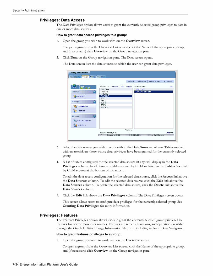
Security Administration
Privileges: Data AccessThe Data Privileges option allows users to grant the currently selected group privileges to data in one or more data sources.
How to grant data access privileges to a group:
1. Open the group you wish to work with on the Overview screen.
To open a group from the Overview List screen, click the Name of the appropriate group, and (if necessary) click Overview on the Group navigation pane.
2. Click Data on the Group navigation pane. The Data screen opens.
The Data screen lists the data sources to which the user can grant data privileges.
3. Select the data source you wish to work with in the Data Sources column. Tables marked with an asterisk are those whose data privileges have been granted for the currently selected group.
4. A list of tables configured for the selected data source (if any) will display in the Data Privileges column. In addition, any tables secured by Child are listed in the Tables Secured by Child section at the bottom of the screen.
To edit the data access configuration for the selected data source, click the Access link above the Data Sources column. To edit the selected data source, click the Edit link above the Data Sources column. To delete the selected data source, click the Delete link above the Data Sources column.
5. Click the Edit link above the Data Privileges column. The Data Privileges screen opens.
This screen allows users to configure data privileges for the currently selected group. See Granting Data Privileges for more information.
Privileges: FeaturesThe Features Privileges option allows users to grant the currently selected group privileges to features for one or more data sources. Features are screens, functions, and operations available through the Oracle Utilities Energy Information Platform, including tables in Data Navigator.
How to grant features privileges to a group:
1. Open the group you wish to work with on the Overview screen.
To open a group from the Overview List screen, click the Name of the appropriate group, and (if necessary) click Overview on the Group navigation pane.
7-34 Energy Information Platform User’s Guide

Security Administration
2. Click Features on the Group navigation pane. The Features screen opens, displaying an expandable tree that contains all the features that can be granted.
3. Select the data source you wish to work with in the Data Sources column. Tables marked with an asterisk are those whose features privileges have been granted for the currently selected group.
4. Assign features privileges for the group as appropriate in the Feature Privileges tree.
The tree provides a graphic representation of the menu items, functions, and fields that can be secured. The tree displays these in a hierarchical structure similar to the structure of the Left Menu. Each line of this structure is referred to as a node. Each menu item, function, or field represented on the tree is referred to as an element.
Each of the menu items and functions accessible and securable in the application (such as Account Management, Set Preferences, etc.) are listed in the tree. The menu items and/or commands that can be secured for each main menu item are listed beneath each main menu node. Clicking the “+” next to a node opens the tree branch of that node, displaying its child nodes. Clicking the “-” closes the tree branch of that node.
Each element on the tree has a corresponding checkbox. Selecting an element enables the menu item and/or function for the role. For example, to enable users with the “Admin” group to access the Locales tab on the Set Preferences screen, you would select the Locales element. Checking a child element will check all parents of that element. Unchecking an element will uncheck all children of that element.
Some elements can be further secured by enabling/disabling or restricting specific operations related to the element. These restrictions are represented by element attributes.
There are two types of element attributes: permission attributes and value attributes. Permission attributes enable/disable access to the function or operation they represent. For example, each of the Security functions (Data Sources, Groups, Users, Data Privileges, and Sessions) includes a “Delete” permission attribute that allows enabling/disabling of the Delete operation of each of the Security functions. Value attributes restrict operations by a minimum or maximum value. For example, some functions can be restricted so that users can only perform those functions based on a minimum or maximum value.
All element attributes appear on the same node of the tree as their respective element. Each permission attribute has a corresponding checkbox. Each value (Min/Max) attribute has a corresponding text box in which the appropriate value can be entered.
Element attributes are disabled if their corresponding element is not checked, including all descending attributes.
To select all elements and attributes, press and hold the Ctrl key and click the Features icon
( ).
5. Click Save Features to save the changes. To delete all feature privileges for the selected data source, click Delete Privileges. To cancel without saving the changes, click Refresh (which returns you to the last screen you viewed).
Members: List Data SourcesThe List Data Sources screen displays a list of all the data sources and indicates which associated with the currently selected group. Data sources are considered associated to a group if the group has Feature Privileges defined for that data source. See Data Sources, above for more information about data sources.
How to view a list of data sources associated to a group:
1. Open the group you wish to view on the Data Sources screen.
To open a group from the Overview List screen, click the ID of the appropriate group, and (if necessary) click List Data Sources on the Group navigation pane.
Tools 7-35

Security Administration
The List Data Sources screen displays a list of all the data sources associated with the group. The presence of one or more icons in the Secured column indicates if Navigator Features and/or Data Access has been configured for each data source. The presence of one or more icons in the Group column indicates if Features and/or Data privileges for the data source have been assigned for the currently selected group.
2. To view a data source on the list, click the data source ID. The selected data source will open on the Data Source Overview screen.
Members: List UsersThe List Users screen displays a list of all the users and indicates which are associated with the currently selected group. Users are associated with groups using the Users screen. See Users, below for more information about users.
How to view a list of users associated to a group:
1. Open the group you wish to view on the Users screen.
To open a group from the Overview List screen, click the Name of the appropriate group, and (if necessary) click List Users on the Group navigation pane.
The List Users screen displays a list of all the users associated with the group, including the user ID, profile, and default data source for each.
2. To view a user on the list, click the user ID. The selected user will open on the Users Overview screen.
How to associate one or more users to a group:
1. Open the group you wish to view on the Users screen.
To open a group from the Overview List screen, click the Name of the appropriate group, and (if necessary) click Users on the Group navigation pane.
The Users screen displays a list of all the users associated with the group, including the user ID, profile, and default data source for each.
2. Check the checkbox(es) for the users to be associated to the group.
3. Click Set Users to save your settings. To cancel without saving the changes, click Refresh.
Icon Meaning
• Secured Column: Indicates that Navigator Features have been configured for the data source. Clicking this icon opens the Configuration: Features screen for the data source.
• Group Column: Indicates that Feature Privileges have been assigned to the currently selected group. Clicking this icon opens the Privileges: Features screen for the selected group.
• Secured Column: Indicates that Data Access has been configured for the data source. Clicking this icon opens the Configuration: Data Access screen for the data source.
• Group Column: Indicates that Data Privileges have been assigned to the currently selected group. Clicking this icon opens the Privileges: Data Access screen for the selected group.
7-36 Energy Information Platform User’s Guide

Security Administration
UsersThe Users screens allow administrators to maintain and update users in the Security system. Clicking on the Users tab opens the User overview screen, which includes the following options:
• Summary: Overview
• Summary: Profiles
• Privileges: Data Access
• Privileges: Features
• Members: List Data Sources
• Members: List Users
As the user moves from the screen to screen while working with users, the currently selected user is indicated at the top of the User navigation pane.
Note: If this is the first time working with Users, the Users search screen opens instead of the overview screen. Click Search and then the User ID of the user you wish to work with, and the selected user will open in the Overview screen.
Summary: OverviewThe Overview screen provides basic information about the currently selected user, and provides several options for creating and maintaining users.
How to view a list of users:
1. Click List Users on the Overview screen. The User Search screen opens.
2. Enter a value to base the search on in the User ID field.
You can use the percent sign (“%”) as a wildcard character when entering values in the User ID field. The User ID field automatically appends a wildcard character to the end of any search criteria you enter. For example, if you want to search for all users that begin with the letter G, you could simply enter “G” in the User ID field.
If you want to search for all users that contain the letter G, you could enter “%G” in the User ID field, and the search would retrieve all users that contain the letter G.
User searches are case-insensitive, meaning you can search for the letter “g” or “G” and retrieve the same results.
3. Select a Group from the Group drop-down list. To search for users of any group, select the top (blank) line from the drop-down list. Click Search.
4. The results appear on the Users List screen.
This screen lists all the users that match the search criteria. To view a user, click the User link. The user opens on the last accessed screen. For instance, if you were granting feature privileges for a user, and then viewed the list and selected a different user from the list, the selected user would open in the Privileges: Features screen.
Tools 7-37

Security Administration
How to add a new user in Default mode:
1. Click Add User on the Overview screen. A blank Overview screen opens.
2. Enter a user id for the new user in the ID field. IDs can be from 1 to 64 characters in length and can include upper and lower case letters. User names are case-insensitive. For example, there is no difference between the “Admin” and “admin” users.
3. Enter a password for the user in the Password field. By default, passwords can be from 1 to 64 characters in length, can include upper and lower case letters as well as numbers, and are case-sensitive. For example, there is a difference between “Password” and “password”. Password-related requirements specified in the LSSECURE.CFG.XML configuration file can override these defaults.
4. Enter the password again in the Confirm Password field.
5. Enter an optional profile in the Profile field. The default profile for all new users is “(Default)”. See Summary: Profiles, below for more information about profiles.
6. To disable the user ID, check the Disabled checkbox.
7. Enter an optional email address in the Email field. This is used in the From field when sending email from the View Reports screen.
8. Click Save to save the new user. To cancel without saving the user, click Refresh (which returns you to the last screen you viewed).
How to add a new user in LDAP mode:
1. Click Add User on the Overview screen. The Overview screen opens with a list of users in the LDAP server that can be granted access to Oracle Utilities applications.
The list displays only the first 25 users in the LDAP server.
If the user you wish to add does not appear on the list, you can search the LDAP server.
To search the LDAP server, enter a value to base the search on in the LDAP Search (ID) field and click Search. The list will display only those LDAP user IDs that match the search criteria.
You can use the percent sign (“%”) as a wildcard character when entering values in the LDAP Search (ID) field. The field automatically appends a wildcard character to the end of any search criteria you enter. For example, if you want to search for all users that begin with the letter G, you could simply enter “G” in the LDAP Search (ID) field.
If you want to search for all users that contain the letter G, you could enter “%G” in the LDAP Search (ID) field, and the search would retrieve all users that contain the letter G.
User searches are case-insensitive, meaning you can search for the letter “g” or “G” and retrieve the same results.
To specify the number of user IDs displayed on the list, enter the desired number in the Result Size field.
2. Select the user you wish to add from the ID drop-down.
3. Enter an optional profile in the Profile field. The default profile for all new users is “(Default)”. See Summary: Profiles, below for more information about profiles.
4. To disable the user ID, check the Disabled checkbox.
5. Enter an optional email address in the Email field. This is used in the From field when sending email from the View Reports screen.
6. Click Save to save the new user. To cancel without saving the user, click Refresh (which returns you to the last screen you viewed).
7-38 Energy Information Platform User’s Guide

Security Administration
How to change a user’s password:
1. Click Change Password.
The Change Password dialog opens.
2. Enter the new password in the Password and Confirm Password fields. By default, passwords can be from 1 to 64 characters in length, can include upper and lower case letters as well as numbers, and are case-sensitive. For example, there is a difference between “Password” and “password”. Password-related requirements specified in the LSSECURE.CFG.XML configuration file can override these defaults. Also, any password-related requirements are displayed in the Change Password dialog.
3. Click Save to save the new password. Click Cancel to close the dialog without changing the user’s password.
How to delete an existing user:
1. Click Delete User.
A confirmation dialog opens asking you to verify that you want to delete the user.
2. Click OK to delete the user. Click Cancel to close the dialog without deleting the user.
Summary: ProfilesThe Profiles screen displays a list of profiles for the currently selected user, and provides several options for creating and maintaining user profiles.
How to add a new profile for a user:
1. Open the user you wish to work with on the Profiles screen.
To open a user from the Overview List screen, click the ID of the appropriate user, and (if necessary) click Profiles on the User navigation pane.
2. Click Add Profile. A blank Profile screen opens.
3. Enter a name for the new profile in the Profile field. Profile names can be from 1 to 64 characters in length and can include upper and lower case letters. User names are case-sensitive. For example, there is a difference between the “Admin” and “admin” profiles.
4. Click Save Profile to save the new user profile. To cancel without saving the profile, click Refresh (which returns you to the last screen you viewed).
Tools 7-39

Security Administration
How to delete an existing profile:
1. Select the profile you wish to delete from the Profile list screen by clicking the corresponding User link. The currently selected profile will be highlighted in blue.
1. Click Delete Profile.
A confirmation dialog opens asking you to verify that you want to delete the profile.
2. Click OK to delete the profile. Click Cancel to close the dialog without deleting the profile.
Privileges: Data AccessThe Data Privileges option allows users to grant the currently selected user privileges to data in one or more data sources.
How to grant data access privileges to a user:
1. Open the user you wish to work with on the Overview screen.
To open a user from the Overview List screen, click the ID of the appropriate user, and (if necessary) click Overview on the Group navigation pane.
2. Click Data on the User navigation pane. The Data screen opens.
The Data screen lists the data sources to which the user can grant data privileges.
3. Select the data source you wish to work with in the Data Sources column. Tables marked with an asterisk are those whose data privileges have been granted for the currently selected user.
4. A list of tables configured for the selected data source (if any) will display in the Data Privileges column. In addition, any tables secured by Child are listed in the Tables Secured by Child section at the bottom of the screen.
To edit the data access configuration for the selected data source, click the Access link above the Data Sources column. To edit the selected data source, click the Edit link above the Data Sources column. To delete the selected data source, click the Delete link above the Data Sources column.
5. Click the Edit link above the Data Privileges column. The Data Privileges screen opens.
This screen allows users to configure data privileges for the currently selected user. See Granting Data Privileges for more information.
Privileges: FeaturesThe Features Privileges option allows users to grant the currently selected user privileges to features for one or more data sources. Features are screens, functions, and operations available through the Oracle Utilities Energy Information Platform, including tables in Data Navigator.
How to grant features privileges to a user:
1. Open the user you wish to work with on the Overview screen.
To open a user from the Overview List screen, click the ID of the appropriate user, and (if necessary) click Overview on the User navigation pane.
2. Click Features on the User navigation pane. The Features screen opens, displaying an expandable tree that contains all the features that can be granted.
3. Select the data source you wish to work with in the Data Sources column. Tables marked with an asterisk are those whose features privileges have been granted for the currently selected user.
4. Assign features privileges for the user as appropriate in the Feature Privileges tree.
The tree provides a graphic representation of the menu items, functions, and fields that can be secured. The tree displays these in a hierarchical structure similar to the structure of the
7-40 Energy Information Platform User’s Guide

Security Administration
Left Menu. Each line of this structure is referred to as a node. Each menu item, function, or field represented on the tree is referred to as an element.
Each of the menu items and functions accessible and securable in the application (such as Account Management, Set Preferences, etc.) are listed in the tree. The menu items and/or commands that can be secured for each main menu item are listed beneath each main menu node. Clicking the “+” next to a node opens the tree branch of that node, displaying its child nodes. Clicking the “-” closes the tree branch of that node.
Each element on the tree has a corresponding checkbox. Selecting an element enables the menu item and/or function for the role. For example, to enable users with the “Admin” group to access the Locales tab on the Set Preferences screen, you would select the Locales element. Checking a child element will check all parents of that element. Unchecking an element will uncheck all children of that element.
Some elements can be further secured by enabling/disabling or restricting specific operations related to the element. These restrictions are represented by element attributes.
There are two types of element attributes: permission attributes and value attributes. Permission attributes enable/disable access to the function or operation they represent. For example, each of the Security functions (Data Sources, Groups, Users, Data Privileges, and Sessions) includes a “Delete” permission attribute that allows enabling/disabling of the Delete operation of each of the Security functions. Value attributes restrict operations by a minimum or maximum value. For example, some functions can be restricted so that users can only perform those functions based on a minimum or maximum value.
All element attributes appear on the same node of the tree as their respective element. Each permission attribute has a corresponding checkbox. Each value (Min/Max) attribute has a corresponding text box in which the appropriate value can be entered.
Element attributes are disabled if their corresponding element is not checked, including all descending attributes.
To select all elements and attributes, press and hold the Ctrl key and click the Features icon
( ).
5. Click Save Features to save the changes. To delete all feature privileges for the selected data source, click Delete Privileges. To cancel without saving the changes, click Refresh (which returns you to the last screen you viewed).
Members: List Data SourcesThe List Data Sources screen displays a list of all the data sources and indicates which are associated with the currently selected user. Data sources are considered associated to a user if the user has Feature Privileges defined for that data source. See Data Sources, above for more information about data sources.
How to view a list of data sources associated to a user:
1. Open the user you wish to view on the Data Sources screen.
To open a user from the Overview List screen, click the ID of the appropriate user, and (if necessary) click List Data Sources on the User navigation pane.
The List Data Sources screen displays a list of all the data sources associated with the user. The presence of one or more icons in the Secured column indicates if Navigator Features and/or Data Access has been configured for each data source. The presence of one or more icons in the Personal column indicates if Features and/or Data privileges for the data source have been assigned for the currently selected user. The presence of one or more numbers in
Tools 7-41

Security Administration
the Group column indicates the number of groups the currently selected user belongs to for which Features and/or Data privileges for the data source have been assigned..
2. To view a data source on the list, click the data source ID. The selected data source will open on the Data Source Overview screen.
Viewing User and Data Source RelationshipsAs users become associated with data sources (through assigning the user Features Privileges for a data source) and with groups, it’s important to be able to keep track of those relationships easily. The Users diagraph is a tool that illustrates these user/group/data source relationships.
How to open the Users Digraph:
1. Click View Digraph on the Data Sources screen. The Users Digraph opens.
This window displays the relationships (if any) between the currently selected user and any groups and/or data sources the user is associated with. The top of the window includes a legend that explains what each symbol in the picture represents.
Members: List GroupsThe List Groups screen displays a list of all the groups and indiciates which are associated with the currently selected users. Groups are associated with users using the Groups screen. See Groups, above for more information about groups.
How to view a list of groups associated to a user:
1. Open the user you wish to view on the List Groups screen.
To open a user from the Overview List screen, click the ID of the appropriate user, and (if necessary) click List Users on the Group navigation pane.
The List Groups screen displays a list of all the groups associated with the user, including the group Name for each.
2. To view a group on the list, click the group Name. The selected group will open on the Groups Overview screen.
How to associate one or more users to a group:
1. Open the user you wish to view on the List Groups screen.
To open a user from the Overview List screen, click the ID of the appropriate user, and (if necessary) click Users on the Group navigation pane.
The Groups screen displays a list of all the groups associated with the user, including the group Name for each.
Icon Meaning
• Secured Column: Indicates that Navigator Features have been configured for the data source. Clicking this icon opens the Configuration: Features screen for the data source.
• Personal Column: Indicates that Feature Privileges have been assigned to the currently selected user. Clicking this icon opens the Privileges: Features screen for the selected user.
• Secured Column: Indicates that Data Access has been configured for the data source. Clicking this icon opens the Configuration: Data Access screen for the data source.
• Personal Column: Indicates that Data Privileges have been assigned to the currently selected user. Clicking this icon opens the Privileges: Data Access screen for the selected user.
7-42 Energy Information Platform User’s Guide

Security Administration
2. Check the checkbox(es) for the group(s) to be associated to the user.
3. Click Set Groups to save your settings. To cancel without saving the changes, click Refresh.
SessionsThe Sessions screens allow administrators to view and end current sessions in the Security system. Session-related functions include ending selected sessions and ending all sessions, and viewing the status of login attempts. Clicking on the Sessions tab opens the Current Sessions screen.
Sessions: CurrentThe Current Sessions screen displays the User, session start time (Started) and the last activity for the session (Last Visit) for each current session.
How to End Specified Sessions:
1. On the Sessions List screen, select the sessions to be ended by checking the checkbox in the far left column, and click End Selected Sessions.
A confirmation dialog opens asking you to verify that you want to end the selected sessions. Click OK to end the sessions.
How to End All Sessions:
1. On the Sessions List screen, click End All Sessions.
A confirmation dialog opens asking you to verify that you want to end all sessions. Click OK to end the sessions.
Logins: All LoginsThe All Logins screen lists the last (or most current) login attempt for each user, including both successful and failed login attempts. For each login attempt listed, this screen displays the following:
• User: the User ID used for the login attempt.
• Status: The current status of the User ID. Can be Active, Disabled, or Nonexistent.
• Time: the time of the last login attempt.
• Success: whether or not the login attempt was successful (Yes or No) .
By default this screen lists all login attempts stored in the database. To filter the list based on a specified date range, select the appropriate date/time values in the “Most recent between” and the “and” fields by either typing the date and time manually, or clicking the arrow to the right of the field and selecting the date using the calendar control.
How to Delete Login History for All Logins:
1. Specify the date range over which you wish to delete the login history using the calendar controls. To delete the entire history, leave the “Most recent between” and the “and” fields blank.
2. Click Delete History in Range.
A confirmation dialog opens asking you to verify that you want to delete all login attempts within the specified range.
Tools 7-43

Security Administration
3. Click OK to delete the records. Click Cancel to close the dialog without deleting the records.
Logins: Successful LoginsThe Successful Logins screen lists the last (or most current) successful login attempt for each user. For each login attempt listed, this screen displays the following:
• User: the User ID used for the login attempt.
• Status: The current status of the User ID. Can be Active, Disabled, or Nonexistent.
• Time: the time of the last login attempt.
• Success: whether or not the login attempt was successful (Yes) .
By default this screen lists all successful login attempts stored in the database. To filter the list based on a specified date range, select the appropriate date/time values in the “Most recent between” and the “and” fields by either typing the date and time manually, or clicking the arrow to the right of the field and selecting the date using the calendar control.
How to Delete Login History for Successful Logins:
1. Specify the date range over which you wish to delete the login history using the calendar controls. To delete the entire history, leave the “Most recent between” and the “and” fields blank.
2. Click Delete History in Range.
A confirmation dialog opens asking you to verify that you want to delete all successful login attempts within the specified range.
3. Click OK to delete the records. Click Cancel to close the dialog without deleting the records.
Failed Logins: All Failed LoginsThe All Failed Logins screen lists the last (or most current) failed login attempt for each user. For each login attempt listed, this screen displays the following:
• User: the User ID used for the login attempt.
• Status: The current status of the User ID. Can be Active, Disabled, or Nonexistent.
• Time: the time of the last login attempt.
• Success: whether or not the login attempt was successful (No) .
By default this screen lists all failed login attempts stored in the database. To filter the list based on a specified date range, select the appropriate date/time values in the “Most recent between” and the “and” fields by either typing the date and time manually, or clicking the arrow to the right of the field and selecting the date using the calendar control.
How to Delete Login History for All Failed Logins:
1. Specify the date range over which you wish to delete the login history using the calendar controls. To delete the entire history, leave the “Most recent between” and the “and” fields blank.
2. Click Delete History in Range.
A confirmation dialog opens asking you to verify that you want to delete all failed login attempts within the specified range.
3. Click OK to delete the records. Click Cancel to close the dialog without deleting the records.
7-44 Energy Information Platform User’s Guide

Security Administration
Failed Logins: Existing UsersThe Existing Users screen lists the last (or most current) failed login attempt for each existing user. For each login attempt listed, this screen displays the following:
• User: the User ID used for the login attempt.
• Status: The current status of the User ID. Can be Active, Disabled, or Nonexistent.
• Time: the time of the last login attempt.
• Success: whether or not the login attempt was successful (No) .
By default this screen lists all failed login attempts for existing users stored in the database. To filter the list based on a specified date range, select the appropriate date/time values in the “Most recent between” and the “and” fields by either typing the date and time manually, or clicking the arrow to the right of the field and selecting the date using the calendar control.
How to Delete Login History for Existing Users:
1. Specify the date range over which you wish to delete the login history using the calendar controls. To delete the entire history, leave the “Most recent between” and the “and” fields blank.
2. Click Delete History in Range.
A confirmation dialog opens asking you to verify that you want to delete all login attempts for existing users within the specified range.
3. Click OK to delete the records. Click Cancel to close the dialog without deleting the records.
Failed Logins: Nonexistent UsersThe Nonexistent Users screen lists the last (or most current) failed login attempt for all nonexistent user IDs used in login attempts. For each login attempt listed, this screen displays the following:
• User: the User ID used for the login attempt.
• Status: The current status of the User ID. Can be Active, Disabled, or Nonexistent.
• Time: the time of the last login attempt.
• Success: whether or not the login attempt was successful (No) .
By default this screen lists all failed login attempts for nonexistent users stored in the database. To filter the list based on a specified date range, select the appropriate date/time values in the “Most recent between” and the “and” fields by either typing the date and time manually, or clicking the arrow to the right of the field and selecting the date using the calendar control.
How to Delete Login History for Nonexistent Users:
1. Specify the date range over which you wish to delete the login history using the calendar controls. To delete the entire history, leave the “Most recent between” and the “and” fields blank.
2. Click Delete History in Range.
A confirmation dialog opens asking you to verify that you want to delete all login attempts for nonexistent users within the specified range.
3. Click OK to delete the records. Click Cancel to close the dialog without deleting the records.
Tools 7-45

Security Administration
Granting Data PrivilegesThe Data Privileges screens allow administrators to grant access to secured tables for a user or group. Adminstrators open the Data Privileges screen by selected the data source and table to which they wish to grant access on the Privileges: Data Access screen (for either the Group or User). The Data Privileges overview screen includes the following options:
• Summary: Overview
• Summary: Test Access
• Summary: View Access
• Keys: View/Delete
• Keys: Add
• SQLEditor: Plain Text
As the administrator moves from the screen to screen while working with data privileges, the currently selected table is indicated at the top of the Data Privileges navigation pane.
Summary: OverviewThe Overview screen provides an overview of the data privileges granted for the currently selected table for the current user/group.
This screen displays the following information:
• User (or Group): The current user or group for which data access privileges are being granted.
• Data Source: The data source in which the table for which data access privileges are being granted resides.
• Table: The currently selected table for which data access privileges are being granted. An asterisk next to the table name indicates that data access (of some sort) has been granted to the table. To select a different table, select the desired table from the drop-down list. This list is defined by the tables directly secured for the data source (see Configuration: Data Access, above for more information).
• All (checkbox): A checkbox that, if checked, indicates that the user or group has been granted access to all records in the currently selected table. By default, all tables have the All checkbox disabled.
• Allow Null (checkbox): A checkbox that, if checked, specifies that records in tables that use this table as a parent or lookup are not restricted if the value is NULL. For example, when securing the Account table, access to all child and descendent records is also automatically restricted via inherited indirect security. However, records in child tables (such as Bill History) where the Account ID column is NULL would not be restricted.By default, all tables have the Allow Null checkbox enabled.
• Plain Text: The SQL query, if any, defined for the currently selected table. See SQLEditor: Plain Text below, for more information.
• Keys: A list of specific records, known as Keys, in the currently selected table that the user or group has been granted access to.
7-46 Energy Information Platform User’s Guide

Security Administration
How to grant access to all records in a selected table:
1. Open the Data Privileges screen for the appropriate data source and table.
2. Check the All checkbox.
3. Click Save to save the settings. To cancel without saving the settings, click Refresh.
How to clear privileges for a selected table:
1. Open the Data Privileges screen for the appropriate data source and table.
2. Click Clear Table Privileges.
A confirmation dialog opens asking you to verify that you want to clear the privileges.
3. Click OK to clear the privileges. Click Cancel to close the dialog without clearing the privileges.
Summary: Test AccessThe Test Access screen allows administrators to view the records available to the user/group for the currently selected table and the time required for those records to be retrieved from the database. This tool can aid administrators in tracking potential problems in the security configuration and in fine-tuning the configuration and data privileges as necessary.
This screen displays the following information:
• User (or Group): The current user or group for which data access privileges are being granted.
• Data Source: The data source in which the table for which data access privileges are being granted resides.
• Table: The currently selected table for which data access privileges are being granted. An asterisk next to the table name indicates that data access (of some sort) has been granted to the table. To select a different table, select the desired table from the drop-down list. This list is defined by the tables directly secured for the data source (see Configuration: Data Access, above for more information).
• Table: The currently selected table (from the Table drop-down list above)
• Mode: The current mode in which records are displayed. There are three modes:
• One Table: In this mode, only the security on the currently selected table is considered when displaying records.
• One Table with Dependencies: In this mode, the effects of security on the currently selected and its children and descendants, but not tables secured using specified indirect security (tables secured via child), are considered when displaying records. In this mode, it is as if all other tables were removed from the Data Access configuration.
• All Tables: All data privileges for the user or group and data source are considered, including those resulting from specified indirect security (tables secured via child), when displaying records.
• Combined (checkbox): This checkbox is visible only when granting data access for users. If this checkbox is checked records are displayed based on combined data privileges for the user and any groups the user is a member of. By default, the Combined checkbox is disabled.
• Not Optimized (checkbox): If checked, the records are retrieved using a non-optimized version of the query being used to grant access to the currently selected table. By default, the Not Optimized checkbox is disabled.
• Record List: A list of records currently accessible by the user or group. This list displays all the columns for each record listed.
Tools 7-47

Security Administration
If there is more than one page of records, you can move between pages using the navigation controls.
Using the button to move to the previous page, and the button to move to the next
page. Use the button to return to the first page, and the button to navigate to the last page. To change the number of results that appears on each page, enter the number in the Rows field.
• Time: The time, in seconds, it takes for the query being used to grant access to the currently selected table to return the list of accessible records. The time is displayed to the immediate right of the navigation controls above the record list.
How to test access for a selected table:
1. Open the Data Privileges screen for the appropriate data source and table.
2. Click Test Access on the Data Privileges navigation pane. The Test Access screen opens.
3. Select the appropriate mode (One Table, One Table with Dependencies, or All Tables).
The records accessible by the user or group for the selected table and the time to retrieve those records is displayed.
4. Optional. Check Not Optimized to observe the impact of a non-optimized query.
The records accessible by the user or group for the selected table and the time to retrieve those records is displayed.
5. To test access for a different directly secured table in the same data source, select the table from the Table drop-down list and repeat steps 2 and 3 above.
How to test combined access for a selected table (users only):
1. Open the Data Privileges screen for the appropriate data source and table.
2. Click Test Access on the Data Privileges navigation pane. The Test Access screen opens.
3. Select the appropriate mode (One Table, One Table with Dependencies, or All Tables).
4. Check the Combined checkbox.
The records accessible by the user or group for the selected table and the time to retrieve those records is displayed.
5. Optional. Check Not Optimized to observe the impact of a non-optimized query.
The records accessible by the user or group for the selected table and the time to retrieve those records is displayed.
6. To test access for a different directly secured table in the same data source, select the table from the Table drop-down list and repeat steps 2 through 4 above.
7-48 Energy Information Platform User’s Guide

Security Administration
Batch TestThe Batch Test option executes queries for all the tables in the selected data source. Like the Test Access option, the Batch Test can aid administrators in tracking potential problems in the security configuration and in fine-tuning the configuration and data privileges as necessary. When the administrator clicks Batch Test on the Test Access screen, the Batch Test screen opens.
This screen displays the following information:
• User (or Group): The current user or group for which data access privileges are being granted.
• Data Source: The data source in which the table for which data access privileges are being granted resides.
• Table: The table for which the query is being currently executed. This changes as the test proceeds.
• Percentage Complete: A progress bar that indicates the percentage of the test that has completed.
• Tables Queried: A table that lists the performance of the query for each table in the data source, sorted by Time. The most recently run table is highlighted. This includes the following information for each table:
• Table: the name of the table
• Time: the duration, in seconds, of the secured request
• Plain: the duration, in seconds of an unsecured request
• Ratio: the Plain result divided by the Time result
• Count: the number of returned secured records up to 25 (the requested amount)
• Available: the number of returned unsecured records
• Depth: the maximum count of ancestors for any node in secured hierarchy for this table
• Width: the maximum count of elements at the same level in the above hierarchy
• Tables: the count of tables in the above hierarchy
• Unique: the count of unique tables in the above hierarchy
• Status: The status of the query. Can be one of: "OK": no errors, "Plain OK": errors in secured, "<error descr.>": description of error.
The bottom three rows of the table, labeled Max, Min, and Average, display the maximum, minimum, and average values (respectively) for the colums.
How to run a batch test:
1. Open the Data Privileges screen for the appropriate data source and table.
2. Click Test Access on the Data Privileges navigation pane. The Test Access screen opens.
3. Click Batch Test.
The Batch Test screen opens, displaying the results of the test.
4. Optional. To pause the test and download the results to a *.CSV file, click Download CSV.
A File Download dialog opens, allowing the user to either save the file or open it.
5. To restart the test, click Restart. To return the previous screen (the Test Access screen), click Return to Data.
Tools 7-49

Security Administration
Summary: View AccessThe View Access screen allows administrators to view the query being used to grant access to the currently selected table. Like the Test Access option, this tool can aid administrators in tracking potential problems in the security configuration and in fine-tuning the configuration and data privileges as necessary.
This screen displays the following information:
• User (or Group): The current user or group for which data access privileges are being granted.
• Data Source: The data source in which the table for which data access privileges are being granted resides.
• Table: The currently selected table for which data access privileges are being granted. An asterisk next to the table name indicates that data access (of some sort) has been granted to the table. To select a different table, select the desired table from the drop-down list. This list is defined by the tables directly secured for the data source (see Configuration: Data Access, above for more information).
• Table: The currently selected table (from the Table drop-down list above)
• Mode: The current mode in which access is viewed. There are three modes:
• One Table: In this mode, only the security on the currently selected table is considered when viewing access.
• One Table with Dependencies: In this mode, the effects of security on the currently selected and its children and descendants, but not tables secured using specified indirect security (tables secured via child), are considered when viewing access. In this mode, it is as if all other tables were removed from the Data Access configuration.
• All Tables: All data privileges for the user or group and data source are considered, including those resulting from specified indirect security (tables secured via child), when displaying access.
• Combined (checkbox): This checkbox is visible only when granting data access for users. If this checkbox is checked the access is viewed based on combined data privileges for the user and any groups the user is a member of. By default, the Combined checkbox is disabled.
• Not Optimized (checkbox): If checked, a non-optimized version of the query being used to grant access to the currently selected table is displayed. By default, the Not Optimized checkbox is disabled.
• Access: A text box that displays the query being used to grant access to the currently selected table. The query can be viewed as SQL or XML. By default the access query is displayed as SQL. To display the query in XML, click the XML radio button. By selecting between SQL and XML and checking/unchecking the Not Optimized checkbox, there are four distinct views of the access query:
• SQL/Optimized: Default. Displays an optimized query in SQL.
• SQL/Not Optimized: Displays a non-optimized query in SQL.
7-50 Energy Information Platform User’s Guide

Security Administration
• XML/Optimized: Displays a optimized query in XML.
• XML/Not Optimized: Displays a non-optimized query in XML.
How to view access for a selected table:
1. Open the Data Privileges screen for the appropriate data source and table.
2. Click View Access on the Data Privileges navigation pane. The View Access screen opens.
3. Select the appropriate mode (One Table, One Table with Dependencies, or All Tables).
The query used to retrieve records for the user or group for the selected table is displayed.
4. Optional. Check Not Optimized to change the query to a non-optimized version.
The (non-optimized) query used to retrieve records for the user or group for the selected table is displayed.
5. Optional. Select XML to view the query in XML rather than SQL.
6. To view access for a different directly secured table in the same data source, select the table from the Table drop-down list and repeat steps 2 through 4 above.
How to view combined access for a selected table (users only):
1. Open the Data Privileges screen for the appropriate data source and table.
2. Click View Access on the Data Privileges navigation pane. The View Access screen opens.
3. Select the appropriate mode (One Table, One Table with Dependencies, or All Tables).
4. Check the Combined checkbox.
The query used to retrieve records for the user or group for the selected table is displayed.
5. Optional. Check Not Optimized to change the query to a non-optimized version.
The (non-optimized) query used to retrieve records for the user or group for the selected table is displayed.
6. Optional. Select XML to view the query in XML rather than SQL.
7. To view access for a different directly secured table in the same data source, select the table from the Table drop-down list and repeat steps 2 through 5 above.
Tools 7-51

Security Administration
Keys: View/DeleteThe View/Delete Keys screen allows administrators to view and/or delete selected records (or Keys) for which the user or group has been previously granted access. This screen opens when the user selects the View/Delete option on the Data Privileges navigation pane.
This screen displays the following information:
• User (or Group): The current user or group for which data access privileges are being granted.
• Data Source: The data source in which the table for which data access privileges are being granted resides.
• Table: The currently selected table for which data access privileges are being granted. An asterisk next to the table name indicates that data access (of some sort) has been granted to the table. To select a different table, select the desired table from the drop-down list. This list is defined by the tables directly secured for the data source (see Configuration: Data Access, above for more information).
• Keys: A list of keys currently accessible by the user or group. This list displays all the columns for each key listed.
How to delete one or more keys:
1. Select the View/Delete option on the Data Privileges navigation pane. A list of previously assigned keys for the currently selected table appears.
2. Select the key or keys to be deleted by checking the corresponding checkboxes in the far left column of the list.
3. Click Delete Keys.
A confirmation dialog opens asking you to verify that you want to delete the selected keys.
4. Click OK to delete the selected keys. Click Cancel to close the dialog without deleting the selected keys.
Keys: AddThe Add Keys screen allows adminstrators to add keys (records) to which the user or group will have access. This screen opens when the user selects the Add option on the Data Privileges navigation pane.
This screen displays the following information:
• User (or Group): The current user or group for which data access privileges are being granted.
• Data Source: The data source in which the table for which data access privileges are being granted resides.
• Table: The currently selected table for which data access privileges are being granted. An asterisk next to the table name indicates that data access (of some sort) has been granted to the table. To select a different table, select the desired table from the drop-down list. This list is defined by the tables directly secured for the data source (see Configuration: Data Access, above for more information).
• Search screen: A search screen for the currently selected table. The specific fields that appear on the search screen are based on the selected table.
How to search for and select keys:
1. Select the Add option on the Data Privileges navigation pane. A search screen for the currently selected table opens. The specific fields that appear on the search screen are based on the selected table.
7-52 Energy Information Platform User’s Guide

Security Administration
The search screen is similar to that used by Data Navigator. See in the Oracle Utilities Energy Information Platform User’s Guide for more information about using the search screen.
Note: The Keys search screen does not use the Combine with or Case-sensitive options.
2. Enter the search criteria as appropriate and click Search.
The screen displays a list of records that match the search criteria.
If there is more than one page of records, you can move between pages using the navigation controls.
Using the button to move to the previous page, and the button to move to the next
page. Use the button to return to the first page, and the button to navigate to the last page. To change the number of results that appears on each page, enter the number in the Rows field.
3. Select the key or keys to be added by checking the corresponding checkboxes in the far left column of the list.
4. Click Add.
5. The selected records will appear on the View/Delete screen.
SQLEditor: Plain TextThe SQL Editor: Plain Text screen allows administrators to define a SQL query for a WHERE clause that defines the records to which the user or group will have access. This screen opens when the user selects the Plain Text option on the Data Privileges navigation pane.
This screen displays the following information:
• User (or Group): The current user or group for which data access privileges are being granted.
• Data Source: The data source in which the table for which data access privileges are being granted resides.
• Table: The currently selected table for which data access privileges are being granted. An asterisk next to the table name indicates that data access (of some sort) has been granted to the table. To select a different table, select the desired table from the drop-down list. This list is defined by the tables directly secured for the data source (see Configuration: Data Access, above for more information).
• Plain Text: The SQL query for the currently selected table. The query displayed is the WHERE clause.
How to write (or edit) a SQL query for a selected table:
1. Open the Data Privileges screen for the appropriate data source and table.
2. Click Plain Text on the Data Privileges navigation pane. The Plain Text screen opens.
3. Enter (or edit) the SQL query in the Plain Text box. See Writing SQL Queries Using the Plain Text Editor below for more information about writing queries.
4. Click Save SQL to save the query (or changes made to the query. Click Refresh to restore the contents of the text box to the last saved version. Click Clear SQL Text to clear all table privileges, including the SQL query.
5. To write or edit a SQL query for a different directly secured table in the same data source, select the table from the Table drop-down list and enter (or edit) the query.
Tools 7-53
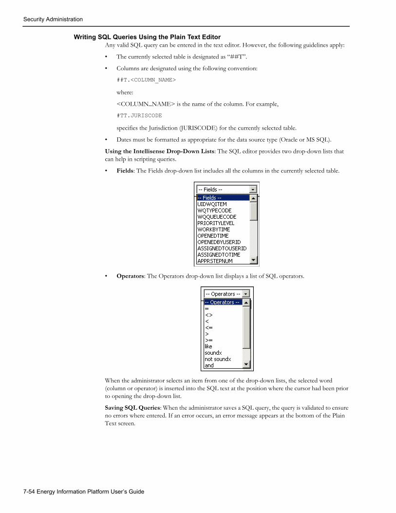
Security Administration
Writing SQL Queries Using the Plain Text EditorAny valid SQL query can be entered in the text editor. However, the following guidelines apply:
• The currently selected table is designated as “##T”.
• Columns are designated using the following convention:
##T.<COLUMN_NAME>
where:
<COLUMN_NAME> is the name of the column. For example,
#TT.JURISCODE
specifies the Jurisdiction (JURISCODE) for the currently selected table.
• Dates must be formatted as appropriate for the data source type (Oracle or MS SQL).
Using the Intellisense Drop-Down Lists: The SQL editor provides two drop-down lists that can help in scripting queries.
• Fields: The Fields drop-down list includes all the columns in the currently selected table.
• Operators: The Operators drop-down list displays a list of SQL operators.
When the administrator selects an item from one of the drop-down lists, the selected word (column or operator) is inserted into the SQL text at the position where the cursor had been prior to opening the drop-down list.
Saving SQL Queries: When the administrator saves a SQL query, the query is validated to ensure no errors where entered. If an error occurs, an error message appears at the bottom of the Plain Text screen.
7-54 Energy Information Platform User’s Guide

Report Administration
Report AdministrationThe Report Administration screen allows users to search, view, edit, and add report templates, report relationships, and report categories. This screen includes three tabs:
• Templates Tab
• Relationships Tab
• Categories Tab
Templates TabThe Templates tab is used to search, view, add, and edit report templates used by the Reporting Framework.
How to search report templates:
1. Select Tools and Utilities-›Report Admin.
The Report Administration screen opens, displaying the Templates tab.
You can search based on the Report Name, Report Type, User ID (who created the report), Output Format, Creation Date, the Priority of the report, whether or not the report is a Base Report, whether or not the report is run in Real Time, a Report Category associated with the report template, a Product associated with the report template, or the report Description.
You can search for reports whose creation dates are Less Than (<), Greater Than (>), Less Than or Equal To (<=), or Greater Than or Equal To (>=) the supplied date by selecting the appropriate operand from the drop-down list.
You can use the percent sign (“%”) as a wildcard character when entering values in any of the text fields. For instance, if you want to search for all reports whose name begins with the letter G, you could enter “G%” in the Name field. You can use this wildcard before or after specified letters or numbers (i.e. you would use %t to search for all reports whose names end with the letter t, etc.).
Note that account Report Names, User IDs, and Descriptions are case-insensitive. For example, there is no difference between the “WQAging” and “wqaging” report names.
2. Specify how the search results are displayed.
• Select the manner in which the results are sorted from the Sort By: drop-down list. You can sort the results by Allow Real Time, Base Report, Creation Date, Description, Output Format, Report Name, Report Type, or User ID.
• Specify how many results should appear on each page in the Page Length field.
3. Click Search to perform the search. To clear all the search fields, click Reset.
4. The search results appear on the Templates tab.
The search results list displays the following information for each report template:
• Report Name: The name of the report template.
• Description: A description of the report template.
• Priority: The priority (High, Medium, or Low) of the report template.
• Type: The type of report template.
• Output Format: The output format for the report template (applies only to templates of type “BIPublisher”).
• Creation Date: The date the report template was created.
Tools 7-55

Report Administration
• User: The User ID of the user who created the report template, or who last updated the template.
• Allow Real Time: A flag that indicates if the report can be run in real time instead of being run in a queue.
• Generate ASP: A flag that indicates if the Report Framework should automatically generate an ASP page that prompts for report parameters when users run the report.
• Base Report: A flag that indicates if the report is provided by Oracle Utilities or is a custom report.
5. To sort the results by one of the columns, click the appropriate column heading. For example, to sort the results by Report Name, click the Report Name column heading. If there is more
than one page of results, you can move between pages using the and buttons. To change the number of results that appears on each page, enter the number in the Rows field and click the Refresh icon.
6. To perform a new search, click New Search. To delete one or more report templates, check the checkbox for the template(s) in the far left column and click Delete. Note: Report templates with a User of “SYSTEM” cannot be deleted.
How to view and/or edit a report template:
1. Select the report template you wish to view or edit by clicking the Report Name link from the search results list. The selected template appears in the Templates tab.
2. Edit the report template as appropriate. You can change the following fields:
• Allow Real Time: A flag that indicates if the report can be run in real time instead of being run in a queue. This flag must be set to “No” when the Report Type is BIPublisher (Oracle BI Publisher).
• Generate ASP: A flag that indicates if the Report Framework should automatically generate an ASP page that prompts for report parameters when users run the report. Note: This flag must be set to “Yes” when the Report Type is LSRate (Oracle Utilities Rules Language) or BIPublisher (Oracle BI Publisher).
• Output Format: The output format for the report template (applies only to templates of type “BIPublisher”). Default formats include:
• BLANK (indicates that the output format is specified when the report is viewed).
• Adobe Acrobat
• Microsoft Excel
• Microsoft Word
• Rich Text Format
For Oracle BI Publisher reports, this list can be changed (to include additional output formats or to remove default output formats) by editing the LSREPORTMONITOR.CFG.XML file.
A specific (non-BLANK) format is required for Oracle BI Publisher reports.
• Priority: The priority for the report template. This determines the priority in which reports are generated. Can be High, Medium, or Low.
• Template File: This is the template file used for the report. For Rules Language reports, this is an XSD for the report. To update the template file, click the Browse button and use the Choose File dialog that opens to locate and select the updated template file.
For Oracle BI Publisher reports, this is a drop-down list that lists the available Oracle BI Publisher reports defined on the BI Publisher server.
• Description: The description of the report.
7-56 Energy Information Platform User’s Guide

Report Administration
• Save To: The file name and destination path for reports generated from the report template.
3. To edit a Rules Langugage report template XSD, click Edit Template. The selected template will open in the Template dialog. See Viewing and Editing LSRate Templates (below) for more information.
4. To export the template (for Oracle Utilities Rules Language reports only), click the Export link.
5. To view an Oracle BI Publisher report, click the BI Publisher link. The Oracle BI Publisher server will open in a new browser window.
6. Click Save to save the changes to the report template. Click Delete to delete the report template. Click Reset to restore all the fields on the report template to their previously saved values. Click Cancel to return to the search results list without changing the report template.
How to add a report template:
1. Click Add on the Templates tab. A blank template screen appears.
2. Enter a Report Name for the report template. The Report Name must be a valid Windows file name, and cannot contain any of the following characters: / \ : * ? " < > |.
3. Select the Report Type for the report template from the drop-down list. Select “BIPublisher” for Oracle BI Publisher Reports. Select “LSRate” for Oracle Utilities Rules Language.
4. For report templates with a Report Type of “BIPublisher”, select an Output Format for the report template. Default formats include:
• BLANK (indicates that the output format is specified when the report is viewed).
• Adobe Acrobat
• Microsoft Excel
• Microsoft Word
• Rich Text Format
This list can be changed (to include additional output formats or to remove default output formats) by editing the LSREPORTMONITOR.CFG.XML file.
For Oracle BI Publisher reports, this list can be changed (to include additional output formats or to remove default output formats) by editing the LSREPORTMONITOR.CFG.XML file.
A specific (non-BLANK) format is required for Oracle BI Publisher reports.
5. Set the Allow Real Time flag (Yes or No) to specify if the report can be run in real time instead of being run in a queue. This flag must be set to “No” when the Report Type is BIPublisher (Oracle BI Publisher).
6. Set the Generate ASP flag (Yes or No) to indicates if the Report Framework should automatically generate an ASP page that prompts for report parameters when users run the report. This flag must be set to “Yes” when the Report Type is LSRate (Oracle Utilities Rules Language) or BIPublisher (Oracle BI Publisher).
7. Select the Priority for the report template (High, Medium, or Low) from the drop-down list. This determines the priority in which reports are generated.
8. Enter a Template File for the report template. This is the XML schema (*.xsd) file used for the Rules Language reports. To add the template file, click the Browse button and use the Choose File dialog that opens to locate and select the updated template file (or *.xsd file).
For Oracle BI Publisher reports, this is a drop-down list that lists the available Oracle BI Publisher reports defined on the BI Publisher server.
Tools 7-57

Report Administration
9. Enter an optional Description for the report template.
10. For report templates with a specified Output Format, specify where reports generated from the template should be saved in the Save To field. This field can specify:
• The destination folder for the report. The default file name for report will be: <ReportName>_<ReportTitle>_<ReportGUID>.ext. The extension will be based on the output format.
• An explicitly specified file path and name.
• Destination file path by using substitute parameters:
Note: Any invalid characters used in file names (/ \ : * ? " < > |) will be replaced with a string equal to “%” plus the character’s hexadecimal code. For example, an asterisk (“*”) would be replaced with “%2A.”
11. Click Save to save the report template. Click Reset to clear all the fields. Click Cancel to return to the search results list without adding the report template.
Viewing and Editing LSRate TemplatesIndividual LSRate templates can be viewed and edited from the Templates tab. See Creating Templates (*.XSD Files) on page 13-26 in the Oracle Utilities Energy Information Platform Configuration Guide for more information about LSRate templates.
How to view and edit LSRate templates:
1. Click on the Edit Template link for the template you wish to view or edit. The selected templates opens in the Template dialog, and displays the following information:
• Template Properties: Basic attributes of the report template, including:
• Template Name: The name of rate schedule in the following format:
<OPCOCODE>_<JURISCODE>_<RATE_FORM_CODE>
where:
• <OPCOCODE> is the Operating Company code associated with the rate schedule.
• <JURISCODE> is the Jurisdiction code associated with the rate schedule.
• <RATE_FORM_CODE> is the Rate Form code of the rate schedule.
Parameter Description
%N Report (Template) Name
%T Report Title
%P Product Code (if the report template is associated to more than one product, the first product code (alphabetically) is used)
%C Report Category (if the report template is associated to more than one category, the first category (alphabetically) is used)
%G Report GUID (global unique identifier)
%A Process ID
%U User ID
%D Run/Schedule time, expressed as YYYY-MM-DD-HH-MI-SS
%E Extension, based on selected output format.
7-58 Energy Information Platform User’s Guide

Report Administration
• Rate Code: The Rate Form code of the rate schedule.
• Operating Company: The Operating Company of the rate schedule.
• Jurisdiction: The Jurisdiction of the rate schedule.
• Attributes Properties: The attributes and properties that define the parameters for the report. Each parameter is defined by the following:
• Attribute Name: is the identifier used in the rate schedule.
• Attribute Type: is the type of parameter.
• Caption: is the name for the parameter that will appear on the user interface
• Properties: Click the plus (“+”) in the far left column to display specific properties for the parameter. See Attribute Properties (below) for more information about attribute properties.
• Script Document: A expandable text box that defines Javascript validations and/or business rules related to values entered for the parameter. Click the Script Document plus (“+”) sign to open the text box.
2. Edit data in the fields as appropriate.
3. To add an attribute, click Add. Enter the attribute name in the Attribute Name column, select the attribute type from the Attribute Type drop-down list, and enter the label for the attribute in the Caption column. See Attribute Properties (below) for more information about attribute properties.
4. To delete an attribute(s), check the corresponding checkbox(es) and click Delete.
5. To edit the Script Document, click the Script Document plus (“+”) sign to open the text box and edit the script as appropriate.
6. To save changes made to the record, click Save.
Attribute PropertiesThe parameters defined in a template are called attributes, and each can be one of the following types:
• String (xs:string): A string (can contain letters or numbers)
• Date (xs:date): A date (e.g. 12/19/2005)
• DateTime (xs:dateTime): A date and time (e.g. 12/19/2005 16:03:45))
• Bill Month (xs:MonthYear): A bill month (12/2005). Note: when used with a date or date time field, bill months are converted to the first day of the selected month.
• Long (xs:long): A long integer
• Double (xs:double):
• Boolean (xs:boolean): A boolean value (indicated by a checkbox on the user interface)
• Lookup (ls:lookup): A lookup value from a table in the Oracle Utilities Data Repository
• Drop-down list (ls:enumeration): A drop-down list of possible values
In addition to the Attribute Name, Attribute Type, and Caption, attributes also have other properties that can be defined. These properties help define default values for attributes, the values available with drop-down list attributes, and other parameters.
There are four types of attribute properties:
Common properties define some default behavior for the attribute, including:
Tools 7-59

Report Administration
• Default Value: The default value of the attribute. This default is overridden if a default value is specified for the Term. Note: Default values for Date and DateTime attributes must be in the “YYYY-MM-DD HH:mm:ss” format.
• Is Required: A flag that designates (Yes or No) whether or not the attribute is required.
• Is Visible: A flag that designates (Yes or No) whether or not the attribute is visible on the user interface.
• Is Disabled: A flag that designates (Yes or No) whether or not the attribute is accessible by the user from the user interface.
Action properties allow Javascript or Javascript functions to be called, and include:
• Event: The name of the action to trigger the script or call the function.
• Function Name: The name of the function called by the action.
• Script: The Javascript called by the action.
Entity properties define lookup attributes, including:
• Table Name: The name of the table in the Oracle Utilities Data Repository that is used by the lookup
• IsUID: A flag that designates (Yes or No) if the lookup field is a UID.
• Entity Fields: Filters applied to the lookup. To apply a filter, enter the column name in the left column, select the appropriate operand, and enter the filtering value in the right column.
Enumeration properties define drop-down lists.
To add an entry to the drop-down list, click Add, enter the value in the left column, and the label in the right column. For example, to create a drop-down list that displays Yes (value = Y) and No (value = N), you would create the following entries:
To delete an entry (or entries), check the corresponding checkbox(es) and click Delete.
Left Column Right Column
Y Yes
N No
7-60 Energy Information Platform User’s Guide

Report Administration
Relationships TabThe Relationships tab is used to search, view, and add report relationships used by the Reporting Framework to associate report templates to specific products, and to group reports by user-specified categories.
Note: You cannot change a report relationship once it has been created. To change the relationship of a report template to specific products and/or categories, you must delete the old relationship and create a new relationship
How to search and view report relationships:
1. Select Tools and Utilities-›Report Admin.
The Report Administration screen opens, displaying the Templates tab. Click the Relationships tab.
You can search based on the Report Name, Product, or Report Category. Select the appropriate values from the drop-down lists.
2. Specify how the search results are displayed.
• Select the manner in which the results are sorted from the Sort By: Product, Report Category, or Report Name.
• Specify how many results should appear on each page in the Page Length field.
3. Click Search to perform the search. To clear all the search fields, click Reset.
4. The search results appear on the Relationships tab.
The search results list displays the following information for each report relationship:
• Report Name: The name of the report.
• Product: The product associated with the report, from the LODESTAR Product table in the Oracle Utilities Data Repository. This determines on which product-specific Run Reports screen the report will appear.
• Report Category: The report category for the report. See Categories Tab on page 7-62 for more information.
5. To sort the results by one of the columns, click the appropriate column heading. For example, to sort the results by Report Name, click the Report Name column heading. If there is more
than one page of results, you can move between pages using the and buttons. To change the number of results that appears on each page, enter the number in the Rows field and click the Refresh icon.
6. To perform a new search, click New Search. To delete one or more report relationships, check the checkbox for the relationship(s) in the far left column and click Delete. Note: Report relationships supplied by Oracle Utilities cannot be deleted.
How to add a report relationship:
1. Click Add on the Relationships tab. A blank relationship screen appears.
2. Select the Report Name for the relationship from the drop-down list.
3. Select the Product for the relationship from the drop-down list.
4. Select an optional Report Category for the relationship from the drop-down list. See Categories Tab on page 7-62 for more information.
5. Click Save to save the report relationship. Click Reset to clear all the fields. Click Cancel to return to the search results list without adding the report relationship.
Tools 7-61

Report Administration
Categories TabThe Categories tab is used to search, view, add, and edit user-specified report categories used by the Reporting Framework to group reports.
How to view report categories:
1. Select Tools and Utilities-›Report Admin.
The Report Administration screen opens, displaying the Templates tab. Click the Categories tab. A list of all report categories appears.
2. To sort the categories by one of the columns, click the appropriate column heading. For example, to sort the results by Report Category, click the Report Category column heading.
If there is more than one page of records, you can move between pages using the and buttons. To change the number of records that appears on each page, enter the number in the Rows field and click the Refresh icon.
3. To delete one or more report categories, check the checkbox for the category(s) in the far left column and click Delete.
How to view/edit a report category:
1. Select the report category you wish to view or edit by clicking the Report Category link from the search results list. The selected category appears in the Relationships tab.
2. Edit the Description of the report category as appropriate.
3. Click Save to save the changes to the report category. Click Reset to restore all the fields on the report category to their previously saved values. Click Cancel to return to the search results list without changing the report category.
How to add a report category:
1. Click Add on the search results list page (on the Categories tab). A blank category screen appears.
2. Enter a name for the Report Category.
3. Enter a Description for the report category.
4. Click Save to save the report category. Click Reset to clear all the fields. Click Cancel to return to the search results list without adding the report category.
7-62 Energy Information Platform User’s Guide

Lists
ListsThe Lists option allows user to create and maintain lists of accounts and customers for use with Oracle Utilities Billing Component, Oracle Utilities Quotations Management, and other applications. The Lists option also allows users to create query lists used with Oracle Utilities Rules Language.
• Account and Customer Lists
• Query Lists
Account and Customer ListsAccount and Customer lists are pre-defined lists of accounts or customers used with Oracle Utilities Billing Component, Oracle Utilities Quotations Management, and other applications.
Note: Account and Customer lists created using the Lists function cannot be edited using Data Manager.
How to search existing lists:
1. Select Tools and Utilities-›Lists.
The Lists screen opens.
2. Enter the search criteria in the appropriate field(s).
You can search based on the Name, Type, Description, Status Code, Public/Private flag, Create Time, Start Time, or Stop Time associated with the list.
You can use the percent sign (“%”) as a wildcard character when entering values in any of the text fields. For instance, if you want to search for all lists whose name begins with the letter G, you could enter “G%” in the Name field. You can use this wildcard before or after specified letters or numbers (i.e. you would use %t to search for all lists whose names end with the letter t, etc.).
Note that Names are case-insensitive. For example, there is no difference between the “List_1” and “list_1” list names.
3. Specify how the search results are displayed.
• Select the manner in which the results are sorted by clicking the Sort by plus (“+”) sign. See Specifying How Results are Sorted on page 2-7 for more information.
• Specify how many results should appear on each page in the Page Length field.
4. Click Search to perform the search. To clear all the search fields, click Reset.
5. The search results appear in the Account (or Customer) Lists screen.
The Account Lists window displays the following information for each list:
• List Name
• Description
• Type
• Status
• Public/Private
• User
• Start Time (Valid After)/Stop Time (Valid Until)/Create Time
6. To sort the results by one of the columns, click the appropriate column heading. For example, to sort the results by Name, click the Name column heading. If there is more than one page
Tools 7-63

Lists
of results, you can move between pages using the and buttons. To change the number of results that appears on each page, enter the number in the Rows field.
7. To select a list, click the Name link. The selected list will open in the Edit List screen. See How to edit an existing list: on page 7-65 for more information.
How to create a new list:
1. Select Add on the Lists screen. The List screen opens.
2. Enter the Name of the list.
3. Select the Type of list, either Account or Customer from the drop-down list.
4. Enter a Description of the list.
5. Select a Status Code for the list from the drop-down list.
6. Select the Public/Private flag for the list from the drop-down list.
7. Enter the Start Time (Valid After) for the list. To enter a date, enter the date manually or click the arrow and select the date using the calendar control.
8. Enter the Stop Time (Valid Until) for the list. To enter a date, enter the date manually or click the arrow and select the date using the calendar control.
9. Click the Create link. The Edit List screen opens.
10. Click the Add Item(s) link. The Accounts (or Customers) window opens.
11. Enter the search criteria in the appropriate field(s).
You can search based on the Customer Name, Customer ID, or an Account ID associated with the account. You can also search based on Account Status, Operating Company, and/or Jurisdiction. To search on one of these, select it from the drop-down lists. In addition, you can search based on contact information such as phone number, address, city/state, etc.
You can use the percent sign (“%”) as a wildcard character when entering values in any of the text fields. For instance, if you want to search for all accounts whose name begins with the letter G, you could enter “G%” in the Name field. You can use this wildcard before or after specified letters or numbers (i.e. you would use %t to search for all accounts whose names end with the letter t, etc.).
Note that account Names, Customer IDs, and Account IDs are case-insensitive. For example, there is no difference between the “Acct_1” and “acct_1” account IDs.
12. Specify how the search results are displayed.
• Select the manner in which the results are sorted by clicking the Sort by plus (“+”) sign. See Specifying How Results are Sorted on page 2-7 for more information.
• Specify how many results should appear on each page in the Page Length field.
13. Click Search to perform the search. To clear all the search fields, click Reset.
14. The search results appear in the Accounts (or Customers) window.
15. Select the accounts (or customers) you wish to add to the list by checking the checkbox in the far left column and click the Save link. To select all the accounts (or customers), check the checkbox in the far left column of the heading row. The selected accounts appear on the Edit List screen.
16. To add more accounts (or customers) to the list, click the Add Items(s) link again. To delete accounts (or customers) from the list, select the accounts (or customers) to delete using the checkboxes in the far left column and click the Remove Selected Item(s) link.
17. Click the Save link to save the list. Click the Reset link to restore the list to the previously saved version. Click the Delete link to delete the list.
7-64 Energy Information Platform User’s Guide

Lists
How to edit an existing list:
1. Select Tools and Utilities-›Lists.
The Lists screen opens.
2. Enter the search criteria in the appropriate field(s).
You can search based on the Name, Type, Description, Status Code, Public/Private flag, Create Time, Start Time, or Stop Time associated with the list.
You can use the percent sign (“%”) as a wildcard character when entering values in any of the fields. For instance, if you want to search for all lists whose name begins with the letter G, you could enter “G%” in the Name field. You can use this wildcard before or after specified letters or numbers (i.e. you would use %t to search for all lists whose names end with the letter t, etc.).
Note that Names are case-insensitive. For example, there is no difference between the “List_1” and “list_1” list names.
3. Specify how the search results are displayed.
• Select the manner in which the results are sorted by clicking the Sort by plus (“+”) sign. See Specifying How Results are Sorted on page 2-7 for more information.
• Specify how many results should appear on each page in the Page Length field.
4. Click Search to perform the search. To clear all the search fields, click Reset.
The results of the search appear in the Account (or Customer) Lists screen.
5. Click the Name of the list you wish to edit. The selected list will open in the Edit List screen.
6. To add accounts (or customers) to the list, click the Add Items(s) link. The Search Accounts (or Customers) window opens.
7. Enter the search criteria in the appropriate field(s).
You can search based on the Account Name, Customer ID, or an Account ID associated with the account. You can also search based on Account Status, Operating Company, and/or Jurisdiction. To search on one of these, select it from the drop-down lists. In addition, you can search based on contact information such as phone number, address, city/state, etc.
You can use the percent sign (“%”) as a wildcard character when entering values in any of the text fields. For instance, if you want to search for all accounts whose name begins with the letter G, you could enter “G%” in the Name field. You can use this wildcard before or after specified letters or numbers (i.e. you would use %t to search for all accounts whose names end with the letter t, etc.).
Note that account Names, Customer IDs, and Account IDs are case-insensitive. For example, there is no difference between the “Acct_1” and “acct_1” account IDs.
8. Specify how the search results are displayed.
• Select the manner in which the results are sorted by clicking the Sort by plus (“+”) sign. See Specifying How Results are Sorted on page 2-7 for more information.
• Specify how many results should appear on each page in the Page Length field.
9. Click Search to perform the search. To clear all the search fields, click Reset.
10. The search results appear in the Accounts (or Customers) window.
11. Select the accounts (or customers) you wish to add to the list by checking the checkbox in the far left column and click the Save link. To select all the accounts (or customers), check the checkbox in the far left column of the heading row. The selected accounts (or customers) appear on the Edit List screen.
Tools 7-65

Lists
12. To delete accounts (or customers) from the list, select the accounts (or customers) to delete using the checkboxes in the far left column and click the Remove Selected Item(s) link.
13. Click the Save link to save the list. Click the Reset link to restore the list to the previously saved version. Click the Delete link to delete the list.
Query ListsQuery lists are structured query language (SQL) queries that can be used by Oracle Utilities Rules Language to access records stored in the Oracle Utilities Data Repository.
Note: Query lists created using the Lists function cannot be edited using Data Manager.
Working with Query ListsThis section outlines how to search, create, and edit query lists.
How to search existing query lists:
1. Select Tools and Utilities-›Lists.
The Lists screen opens.
2. Select Query from the Type drop-down list.
3. Enter other search criteria in the appropriate field(s).
You can search based on the List Name, Description, Status Code, Public/Private flag, Create Time, Start Time, or Stop Time associated with the list.
You can use the percent sign (“%”) as a wildcard character when entering values in any of the text fields. For instance, if you want to search for all lists whose name begins with the letter G, you could enter “G%” in the Name field. You can use this wildcard before or after specified letters or numbers (i.e. you would use %t to search for all lists whose names end with the letter t, etc.).
Note that Names are case-insensitive. For example, there is no difference between the “List_1” and “list_1” list names.
4. Specify how the search results are displayed.
• Select the manner in which the results are sorted by clicking the Sort by plus (“+”) sign. See Specifying How Results are Sorted on page 2-7 for more information.
• Specify how many results should appear on each page in the Page Length field.
5. Click Search to perform the search. To clear all the search fields, click Reset.
6. The search results appear in the Query List screen.
The Query Lists window displays the following information for each list:
• List Name
• Description
• Type (will be Query for all lists displayed)
• Status Code
• Public/Private
• User
• Start Time (Valid After)/Stop Time (Valid Until)/Create Time
7. To sort the results by one of the columns, click the appropriate column heading. For example, to sort the results by Name, click the Name column heading. If there is more than one page
7-66 Energy Information Platform User’s Guide

Lists
of results, you can move between pages using the and buttons. To change the number of results that appears on each page, enter the number in the Rows field.
8. To select a list, click the List Name link. The selected list will open in the Edit List screen. See How to edit an existing list: on page 7-65 for more information.
How to create a new query list:
1. Select Add on the Lists screen. The List screen opens.
2. Enter the Name of the list.
3. Select Query from the Type drop-down list.
4. Enter a Description of the list.
5. Select a Status Code for the list from the drop-down list.
6. Select the Public/Private flag for the list from the drop-down list.
7. Enter the Start Time (Valid After) for the list. To enter a date, enter the date manually or click the arrow and select the date using the calendar control.
8. Enter the Stop Time (Valid Until) for the list. To enter a date, enter the date manually or click the arrow and select the date using the calendar control.
9. Click the Browse button ( ) to open the Query Editor dialog.
10. Define the SQL query for the list. Click OK to close the Query Editor dialog and return to the List screen. See Creating SQL Queries for Query Lists on page 7-68 for more information about creating SQL queries using this screen.
11. A list of results returned by the query (including all columns specified in the query) will be displayed at the bottom of the dialog. If the query requires parameters, click Execute Query, and enter the appropriate parameters in the Query Parameters dialog and click Continue to execute the query and display the results. If there is more than one page of results, you can
move between pages using the and buttons. To change the number of results that appears on each page, enter the number in the Rows field.
12. Click the Create link. The Edit List screen opens.
13. Click the Save link to save the list. Click the Reset link to restore the list to the previously saved version. Click the Delete link to delete the list.
How to edit an existing query list:
1. Select Tools and Utilities-›Lists.
The Lists screen opens.
2. Select Query from the Type drop-down list.
3. Enter other search criteria in the appropriate field(s).
You can search based on the List Name, Description, Status Code, Public/Private flag, Create Time, Start Time, or Stop Time associated with the list.
You can use the percent sign (“%”) as a wildcard character when entering values in any of the fields. For instance, if you want to search for all lists whose name begins with the letter G, you could enter “G%” in the Name field. You can use this wildcard before or after specified letters or numbers (i.e. you would use %t to search for all lists whose names end with the letter t, etc.).
Note that Names are case-insensitive. For example, there is no difference between the “List_1” and “list_1” list names.
4. Specify how the search results are displayed.
Tools 7-67

Lists
• Select the manner in which the results are sorted by clicking the Sort by plus (“+”) sign. See Specifying How Results are Sorted on page 2-7 for more information.
• Specify how many results should appear on each page in the Page Length field.
5. Click Search to perform the search. To clear all the search fields, click Reset.
The results of the search appear in the Account (or Customer) Lists screen.
6. Click the Name of the list you wish to edit. The selected list will open in the Edit List screen.
7. You can edit List Name, Description, Status Code, Public/Private flag, Start Time, or Stop Time, or Query associated with the list.
To edit the SQL query used by the list, click the Browse button ( ) to open the Query
Editor dialog. Edit the SQL as needed. See Creating SQL Queries for Query Lists on page 7-68 for more information about creating SQL queries using the Query Editor dialog. Click OK to close the Query Editor dialog and return to the Edit List screen.
8. A list of results returned by the query (including all columns specified in the query) will be displayed at the bottom of the dialog. If the query requires parameters, click Execute Query, and enter the appropriate parameters in the Query Parameters dialog and click Continue to execute the query and display the results. If there is more than one page of results, you can
move between pages using the and buttons. To change the number of results that appears on each page, enter the number in the Rows field.
9. Click the Save link to save the list. Click the Reset link to restore the list to the previously saved version. Click the Delete link to delete the list.
Creating SQL Queries for Query ListsThe Query Editor dialog is used to define SQL queries used by Query Lists. To open the Query
Editor screen, click the Browse button ( ) next to the Query field on the Edit List screen.
Any valid SQL single “select” statement can be defined for a query list. The statement must begin with the SELECT command. This statement can include the use of inner and outer joins, “where” clauses, and nested “select” statements. Valid SQL syntax is defined by the RDBMS (Oracle or MS SQL Server) being used.
Date parameters should be converted to strings in the Rules Language before being used by query lists. This conversion can be done through use of the DATETIMETOSTRING function (see DATETIMETOSTRING Function on page 13-25 in the Oracle Utilities Rules Language Reference Guide for more information about using this function) or other means of creating strings in the Rules Language. The following sample Rules Language code illustrates how date parameters can be converted into strings using the DATETIMETOSTRING function:
START_STRING = DATETIMETOSTRING(BILL_START, "MM/dd/yyyy HH:mm:ss");STOP_STRING = DATETIMETOSTRING(BILL_STOP, "MM/dd/yyyy HH:mm:ss");
When referencing date parameters within a query, dates must be formatted as appropriate for the RDBMS being used. Oracle Utilities recommends using the SQL conversion functions to ensure proper date formatting. For example, when using an Oracle database, you would use the “to_date” function. The following example illustrates how the “to_date” function can be used within a query list:
SELECT ACCOUNTID, STARTTIME, STOPTIME, OPCOCODE, JURISCODE FROM ##Q.ACCOUNT WHERE STARTTIME > to_date(##P.START1,'MM/DD/YYYY HH24:MI:SS') AND STARTTIME < to_date(##P.START2,'MM/DD/YYYY HH24:MI:SS')
In addition, the following SQL extensions will be used:
• The current database qualifier is designated as “##Q”. All table references must be preceded by “##Q”.
7-68 Energy Information Platform User’s Guide

Lists
• Parameters are designated using the following convention:
##P.<IDENTIFIER>
where:
<IDENTIFIER> is the name of a Rules Language identifier. For example,
##P.ACCT_ID
specifies that the Rules Language identifier ACCT_ID as a parameter used by the query.
The column names of the SQL statement's result set should be valid Rules Language identifiers. See Identifiers on page 4-2 in the Oracle Utilities Rules Language User’s Guide and the Assignment Statement on page 2-2 in the Oracle Utilities Rules Language Reference Guide for more information about Rules Language identifiers This can be achieved by using SQL aliases.
Example:
select min(A.STARTTIME) MIN_ACCOUNT, A.JURISCODEfrom ##Q.ACCOUNT Agroup by A.JURISCODE
Using the Drop-Down Lists: The Query Editor screen provides reference drop-down lists that can help in scripting queries.
• Entities: The Entities drop-down list includes all the tables in the Oracle Utilities Data Repository.
• Fields: The Fields drop-down list includes all the columns in the table selected on the Entities drop-down list.
• Operators: The Operators drop-down list displays a list of valid SQL operators for the field selected in the Fields drop-down list.
To validate the query, click Validate.
To save the query and return to the Edit List screen, click OK. The query will be validated to ensure no errors where entered. If an error occurs, an error message appears at the top of the screen. To close the Query Editor screen without saving the query, click Cancel.
Using Query Lists in Oracle Utilities Rules LanguageQuery lists are intended for use in Oracle Utilities Rules Language via the FOR EACH IN LIST statement and the LISTVALUE function.
Query list behave as follows when executed in Rules Language:
• A query list with one field in the result set will behave as a Table/Column list that does not store the unique key for the table. This means that only one scalar value can be retrieved for each item returned using the FOR EACH IN LIST statement or by calling of the LISTVALUE function.
• A query list with more then one field in the result set will behave similar to a "full record" Table/Column list except that processing of UIDs and access to virtual columns are not supported. This means the following:
• Temporary identifiers assigned using the "FOR EACH IN LIST" statement for each list item will be the "DATABASE VALUES" type. All fields will be accessible via STEM.TAIL syntax where STEM is the name of temporary identifier.
• Results returned from the LISTVALUE function call will be the "DATABASE VALUES" type. All field values will be accessible via STEM.TAIL syntax where STEM is the name of temporary identifier.
• LOB fields are not supported in SQL-based query lists
Tools 7-69

Lists
• The RETURN_UID_FOR_UID_TARGETED_LISTS and TARGET_IDS_FOR_UID_REF_LISTS parameters in LODESTAR.CFG configuration file are not supported.
Query lists are not supported by the following Rules Language functions:
• LISTUPDATE
• LISTOP
• LISTCOUNT*
*Note: LISTCOUNT does not support SQL-based lists when the Rules Language is executed against Microsoft SQL Server and the SQL statement contains the ORDER BY clause. A work around for this case can be accomplished by creating a second list that uses the COUNT function.
7-70 Energy Information Platform User’s Guide

Lists
Query List ExamplesThis section outlines several examples of using query lists in Rules Language.
Example 1: Single column SQL list accessed via FOR EACH IN LIST statement
List (MYACCOUNTS) SQL:
select A.ACCOUNTIDfrom ##Q.ACCOUNT A
Rules Language:
FOR EACH ACCOUNTID IN LIST "MYACCOUNTS" REPORT ACCOUNTID LABEL "Account";END FOR;
Output Report:
Account :GSGP_01
Account :GSGP_02
...
Example 2: Single column SQL list accessed via LISTVALUE function call
List (MYACCOUNTS) SQL:
select A.ACCOUNTIDfrom ##Q.ACCOUNT A
Rules Language:
ACCOUNTID = LISTVALUE("MYACCOUNTS")REPORT ACCOUNTID LABEL "Account";
Output Report:
Account : GSGP_01
Example 3: SQL list with multiple columns accessed via FOR EACH IN LIST statement
List (MYACCOUTSM) SQL:
select A.ACCOUNTID, A.STARTTIMEfrom ##Q.ACCOUNT A
Rules Language:
FOR EACH ACC IN LIST "MYACCOUTSM" LABEL ACC.ACCOUNTID "Account ID"; LABEL ACC.STARTTIME "Start Time"; REPORT ACC LABEL "Accounts";END FOR;
Output Report:
Accounts
Account ID Start Time
GSGP_01 04/09/2003
GSGP_02 02/05/2004
Tools 7-71

Lists
Example 4: SQL list with multiple columns accessed via LISTVALUE function call
List (MYACCOUTSM) SQL:
select A.ACCOUNTID, A.STARTTIMEfrom ##Q.ACCOUNT A
Rules Language:
ACC = LISTVALUE("MYACCOUTSM");LABEL ACC.ACCOUNTID "Account ID";LABEL ACC.STARTTIME "Start Time";
Output Report:
Account ID : GSGP_01
Start Time : 04/09/2003
...
Example 5: Alias for expression in result column accessed via FOR EACH IN LIST statement
List (MYACCOUNTS2) SQL:
select min(A.STARTTIME) MIN_ACCOUNT, A.JURISCODEfrom ##Q.ACCOUNT Agroup by A.JURISCODE
Rules Language:
FOR EACH A1 IN LIST "MYACCOUTS2" LABEL A1.JURISCODE "Jurisdiction"; LABEL A1.MIN_ACCOUNT "Start Time"; REPORT A1 LABEL "Early Starts";END FOR;
Output Result:
Early Starts
Jurisdiction Start Time
NJ 01/29/2002 00:00:00
MA 01/01/1993 00:00:00
DT 01/01/2003 00:00:00
Example 6: Complex SQL list for Oracle Database accessed via FOR EACH IN LIST statement
List (MYACCFACTORUOM) SQL:
select A.ACCOUNTID, NVL(F.UOMCODE, 'NONE') AS UOMCODE, AFH.STARTTIME, F.OPCOCODE || ':' || F.JURISCODE AS OPJUR from ##Q.ACCOUNT A left outer join ##Q.ACCTFACTORHIST AFH on (A.UIDACCOUNT = AFH.UIDACCOUNT) join ##Q.FACTOR F on (F.UIDFACTOR = AFH.UIDFACTOR)
Rules Language:
FOR EACH ACC IN LIST " MYACCFACTORUOM" LABEL ACC.ACCOUNTID "Account ID"; LABEL ACC.UOMCODE "UOM"; LABEL ACC.STARTTIME "Start Time"; LABEL ACC.OPJUR "Opco and Juris"; REPORT ACC LABEL "Special Case";END FOR;
7-72 Energy Information Platform User’s Guide

Lists
Output Report:
Special Case
Account ID UOM Start Time Opco and Juris
GSGP_01 01 04/09/2003 GLOBAL:ALL
GSGP_02 NONE 02/05/2004 GECO:SF
...
Tools 7-73

Run Reports
Run ReportsThe Run Reports option displays reports available through the Energy Information Platform Reporting Framework. From this screen, users can select and run reports. Each product has its own Run Reports option that displays reports associated with that product. For example, the Oracle Utilities Billing Component list displays billing reports, while the Oracle Utilities Receivables Component reports list displays it’s reports.
How to run reports:
1. Select the Run Reports option from the appropriate menu (Tools and Utilities, Work Queues, Billing, Financials, etc.). The Run Reports screen opens.
The Run Reports screen displays the following information for each report:
• Report Name: The name of the report.
• Description: A description of the report.
• Priority: The priority of the report (High, Medium, or Low).
• Type: The type of report (PLBX, LSRate (Oracle Utilities Rules Language), Active, or BIPublisher).
• Output Format: The output format for the report (applies to reports of type “BIPublisher” only).
• Creation Date: The date the report template was created.
• User: The User ID who created the report template.
• Generate ASP: A flag that indicates if the report framework generates an ASP parameters page for the report.
2. Select the report you wish to run by clicking the Report Name link from the list.
The Enter Report Parameters screen opens displaying the report parameters for the selected report.
3. Enter the parameters for the report as appropriate.
The Report Title field is the title that appears on the View Reports screen when the report is run.
4. Select the Priority for the report. This determines the priority (High, Medium, or Low) in which the report will be generated.
5. Uncheck the Shared Report checkbox if you wish to make the results of the report private. If you leave this checkbox checked, the report results will be available to all users.
6. Click Run to run the report. Click Schedule Report to schedule the report using the Schedule Process screen (see Scheduling Reports below, for more information). When the report is complete, the report opens in the appropriate viewer (Active, etc.). In addition, the report is also listed on the View Reports screen.
How to search reports:
1. Click New Search on the Run Reports screen. The Run Reports search screen appears.
You can search based on the Report Name, Report Type, User ID (who created the report or who last updated the report), Output Format, Creation Date, Priority, Report Category, Product, or the report Description.
You can search for reports whose creation dates are Less Than (<), Greater Than (>), Less Than or Equal To (<=), or Greater Than or Equal To (>=) the supplied date by selecting the appropriate operand from the drop-down list.
7-74 Energy Information Platform User’s Guide

Run Reports
You can use the percent sign (“%”) as a wildcard character when entering values in any of the text fields. For instance, if you want to search for all reports whose name begins with the letter G, you could enter “G%” in the Name field. You can use this wildcard before or after specified letters or numbers (i.e. you would use %t to search for all reports whose names end with the letter t, etc.).
Note that account Report Names, User IDs, and Descriptions are case-insensitive. For example, there is no difference between the “WQAging” and “wqaging” report names.
2. Specify how the search results are displayed.
• Select the manner in which the results are sorted from the Sort By: drop-down list. You can sort the results by Creation Date, Description, Report Name, Report Type, or User ID.
• Specify how many results should appear on each page in the Page Length field.
3. Click Search to perform the search. To clear all the search fields, click Reset.
4. The search results appear on the Run Reports screen.
Scheduling ReportsThe Schedule Process screen allows users to define a schedule for running processes unattended.
How to schedule a process:
1. Click Schedule (or Schedule Report). The Schedule Process screen opens.
2. Enter the Start Time for the scheduled process by entering the date and time manually or clicking the arrow and select the date using the calendar control and typing the time manually. See Entering Date and Date/Time Values on page 2-8 for more information about using the calendar control.
Note: The Server Time displayed above the Start Time field is the current time of the web server running the scheduler, including both the location and Time Zone where the server is located. Scheduled processes run based on the server time, not the time on the client machine.
3. Select a Recurrence Pattern for the scheduled process. You can select one of the following:
None: The scheduled process runs only once at the specified start time. Note: Scheduled processes with a recurrence pattern of None ignore Business Calendars and will run on non-business days.
Intra Daily: The scheduled process runs multiple times, from as frequent as once every 15 minutes to once every several hours. To base the recurrence on a number of minutes, select the Every x minutes radio button and select the number from the Minutes drop-down list. To base the recurrence on a number of hours, select the Every x hours radio button and enter the number of hours in the text box. Intra Daily processes may run throughout a single day or may span multiple days.
Daily: The scheduled process runs once per day or once per number of days. To base the recurrence on a number of days, select the Every x days radio button and enter the number of days in the text box. To set the scheduled process to run every weekday, check the Every weekday radio button.
Weekly: The scheduled process runs once or more per week (or number of weeks) on specified days. Enter the number of weeks in the Recur every x week(s) on text box, and check the specific days of the week on which the process should run. For example, to schedule a process to run on Monday and Wednesday every two weeks, you would enter 2 in the Recur every x week(s) on text box and check the Monday and Wednesday checkboxes.
Monthly: The scheduled process runs once per month or once per number of months. A monthly recurrence can be based on either a specific day of the month (such as the the 10th
Tools 7-75

Run Reports
day of the month), or a specific type of day (such as the 2nd Friday of the month). To base the recurrence on a specific day, select the Day x of every x month(s) radio button and enter the specific day and number of months in the text boxes. To base the recurrence on a specific type of day, select the The x x of every x month(s) radio button and select the appropriate number (First, Second, Third, Fourth, or Last) and day (Sunday through Saturday) from the drop-down lists and enter the number of months in the text box.
Important Note: Each execution of a recurring scheduled process uses the original parameters entered for the process.
4. Set the Range of Recurrence for the scheduled process. This specifies how many times the scheduled process will run (based on the specified recurrence pattern). There are three options:
• No end date: To specify no ending date for the recurrence, select the No end date radio button.
• End after occurence: To specify that the recurrence ends after a predetermined number, select the End after occurrence radio button and enter the number of recurrences in the text box.
• End by: To specify a date on which to end the recurrences, select the End by radio button and enter the date and time by which the recurrence should end. Enter the date and time manually or click the arrow and select the date using the calendar control and type the time manually. See Entering Date and Date/Time Values on page 2-8 for more information about using the calendar control.
5. Set any applicable Recurrence Exceptions for the scheduled process. Recurrence exceptions define which business calendar, if any, is used in scheduling and how to handle processes scheduled to run on non-business days. There are two options:
• Business Calendar: To schedule the process using a business calendar, click the Browse
button ( ). This opens a dialog window that lists all the available Business Calendars. Click the [...] link to select the appropriate calendar. The field is automatically populated.
• Roll to next business day: Check this checkbox to specify that a process scheduled to run on a non-business day is rolled forward to the next business day. If the process is already scheduled to run on the next business day, a new process is NOT scheduled.
Note: When using a Business Calendar, if the Start Time entered for a process is later than the last date in the Business Calendar, an error will be returned. Also, for scheduled processes with the No End Date option selected, occurrences that would have occurred on dates later than the last date in the Business Calendar will not occur, and do not appear on the View Reports screen.
7-76 Energy Information Platform User’s Guide

View Reports
View ReportsThe View Reports option displays previously run reports available through the Energy Information Platform Reporting Framework, including other processes such as uploading data via the Upload Usage option. From this screen, users can view and delete reports. Each product has its own View Reports option that displays reports associated with that product. For example, the Oracle Utilities Billing Component View Reports screen displays billing reports, while the Oracle Utilities Receivables Component View Reports screen displays it’s reports.
How to view reports:
1. Select the View Reports option from the appropriate product menu (Tools and Utilities, Work Queues, Billing, Financials, etc.) The View Reports screen opens.
The View Reports screen displays the following information for each report:
• Status Icon: An icon that displays the status of the report. If an output format was specified for the report, the icon indicates the output format. See Report Icons for more information.
• Run/Schedule Time: The time the report was run or is scheduled to run.
• Report Title: The title of the report, specified when the report was run. For LSRate (Oracle Utilities Rules Language) reports, this column will display the name of the Report Template used to generate the report, unless specified using the SETREPORTTITLE Rules Language function.
• Priority: The priority of the report (High, Medium, or Low).
• Type: The type of report (PLBX (Oracle Utilities Billing Component), LSRate (Oracle Utilities Rules Language), Active, or BIPublisher).
• User: The user ID of the user who ran the report.
• Progress: The current percentage of the report instance that has been generated, from 0 to 100 percent.
• Shared: A flag that indicates if the report is shared by all users or is accessible only by the user who ran the report.
• Base: A flag that indicates if the report is provided by Oracle Utilities or is a custom report.
• Process: The (machine) name of the server on which the report was executed.
• Account Name: The name of the account associated with the report, if applicable.
• Account ID: The ID of the account associated with the report, if applicable.
2. To view a specific report, click the Report Title link for the report. The selected report opens in the appropriate viewer.
3. To refresh the contents of the screen, click Refresh Periodically. To have the screen continually refresh its contents, check the Refresh Periodically checkbox.
Note: The current state of the Refresh Periodically checkbox (selected or not) is stored in the user’s settings, and is used as the default setting when subsequently opening this screen.
How to delete reports:
1. Check the checkbox next to the reports(s) to delete. To select all reports, check the top check box.
2. Click Delete.
How to search reports:
1. Click New Search on the View Reports screen. The View Reports search screen appears.
Tools 7-77

View Reports
You can search based on the Report Title, Report Type, User ID (who created the report), Output Format, Creation Date, Report Category, or Product.
You can search for reports whose creation dates are Less Than (<), Greater Than (>), Less Than or Equal To (<=), or Greater Than or Equal To (>=) the supplied date by selecting the appropriate operand from the drop-down list.
You can use the percent sign (“%”) as a wildcard character when entering values in any of the text fields. For instance, if you want to search for all reports whose name begins with the letter G, you could enter “G%” in the Name field. You can use this wildcard before or after specified letters or numbers (i.e. you would use %t to search for all reports whose names end with the letter t, etc.).
Note that account Report Titles, User IDs, and Descriptions are case-insensitive.
2. Specify how the search results are displayed.
• Select the manner in which the results are sorted by clicking the Sort by plus (“+”) sign. See Specifying How Results are Sorted on page 2-7 for more information.
• Specify how many results should appear on each page in the Page Length field.
3. Click Search to perform the search. To clear all the search fields, click Reset.
4. The search results appear on the View Reports screen.
Report IconsThe icon listed next to each report indicates the status of the report. The meanings of these icons are as follows:
Icon Description
Report Starting: Report processing is starting.
Report in Process: Report processing
Report Complete: Report processing is complete.
Report Complete (Adobe Acrobat format): Report processing is complete.
Report Complete (Microsoft Excel format): Report processing is complete.
Report Complete (Microsoft Word format): Report processing is complete.
Report Complete (Rich Text format): Report processing is com-plete.
Report Complete (Comma Separated Values format): Report pro-cessing is complete.
Report Scheduled: Report is scheduled to run at a future time. To
view scheduling details, click the arrow in the far right column. To edit the schedule, click Edit.
Report Reminder: Indicates that a scheduled report is due to run in 15 minutes or less.
7-78 Energy Information Platform User’s Guide

View Reports
Viewing Oracle BI Publisher ReportsWhen you select an Oracle BI Publisher Report, the report opens in a viewer based on the output format defined for the report. For the default output formats, this includes:
• Adobe Acrobat
• Microsoft Excel
• Microsoft Word (for MS Word and Rich Text Format reports. If Microsoft Word is not installed, Rich Text Format reports open in the installed application (if any) associated with the *.rtf file extension).
Viewing Oracle Utilities Rules Language ReportsWhen you select a Oracle Utilities Rules Language Report (one with a Type of LSRate), the report opens in the Report view screen.
The State section above the top left corner of the report displays the state of the report, including the number of Errors, the number of Pages expected and ready, and the elapsed time (in seconds) it took for the report to run.
The From: and To: fields above the top right corner of the report show the current pages
displayed. The From: field displays the current page. The and buttons and the field between them are used to navigate the report. The field between the buttons defines how many pages display in the report window at a time. The default is 1. To display more than one page at a time, enter the number of pages you wish to view in the field.
Emailing ReportsYou can also email reports from the View Reports screen. This allows users to distribute reports to other parties via email.
Note: The Send Email function requires the presence of the LSRELAY.CFG.XML file in the C:\LODESTAR\CFG directory on the web server computer. Contact your system administrator for more information about this file.
How to email a report:
1. Select the report (or reports) you wish to send via email and click Send Email on the View Reports screen.
The Send Email screen opens.
2. Select a From address from the drop-down list. This list is based on available records in the From Addresses table. If there are no available records in the From Addresses table, the current user’s email address is populated (if provided on the User Overview screen on the Security Adminstration user interface).
3. Enter an email address in the To field, or click Address Book (or the “+” sign) to add a contact or group name. See Using the Address Book on page 7-80 for more information about using the Address Book.
Report Error: One or more errors or warnings associated with the report. To view the error, click the Error icon.
Icon Description
Tools 7-79

View Reports
4. Optional. Enter an email address in the CC field, or click Address Book (or the “+” sign) to add a contact or group name. See Using the Address Book on page 7-80 for more information about using the Address Book.
To remove the CC field, click Remove CC.
5. Optional. To add the BCC field, click Add BCC, and enter an email address in the BCC field, or click Address Book (or the “+” sign). See Using the Address Book on page 7-80 for more information about using the Address Book.
6. Enter a subject for the email in the Subject field.
7. Enter the email message in the Message field.
8. To send the email, click Send. To clear all the fields, click Reset.
A message will appear at the top of the View Reports screen after your email has been sent.
Using the Address BookIn addition to entering email addresses manually, you can use the Address Book feature to select email recipients from those defined in the Oracle Utilities Data Repository. The Address Book contains listings of:
• Contacts
• Groups
ContactsContacts are specific individuals related to parties (such as Service Points or Market Participants) defined in the Oracle Utilities Data Repository.
How to select an existing contact from the Address Book:
1. Click Address Book (or the “+” sign) on the Send Email screen.
The Address Book dialog opens on the Contacts tab.
2. Enter the search criteria for the contacts you wish to send email to. You can search by Last Name, First Name, Middle Name, or Company.
3. Specify how the search criteria are to be combined by selecting the appropriate Combine with option (AND or OR), located in the upper right corner of the search screen. The default combine option is AND.
4. Specify whether or not the search is Case-sensitive by checking or unchecking the Case-sensitive checkbox, located in the upper right corner of the search screen. The default setting is case-sensitive.
5. Specify how the search results are displayed.
• Select the manner in which the results are sorted by clicking the Sort by plus (“+”) sign. See Specifying How Results are Sorted on page 2-7 for more information.
• Specify how many results should appear on each page in the Page Length field.
6. Click Search to perform the search. To reset the search fields to their previous values, click Reset. To clear all the search fields, click Clear. To add a new contact to the Address Book, click Add.
7. The search results appear on the Address Book dialog.
7-80 Energy Information Platform User’s Guide

View Reports
8. Select the contact(s) you wish to send the email to and click To. The selected contact(s) will appear in the To field on the Send Email screen.
To remove a contact from the To, CC, or BCC field, select the contact and click the Delete Key, or click the right mouse, and select Remove.
9. Optional. To add a contact to the CC (or BCC) field, select the contact(s) you wish to send the email to and click CC (or BCC as appropriate). The selected contact(s) will appear in the CC (or BCC) field on the Send Email screen.
How to add a contact using the Address Book:
1. Click Add on the Contacts tab of the Address Book dialog.
The Edit Contact screen opens.
2. Enter personal information for the contact (First, Middle, and Last Names, Title, etc.) in the Personal Information pane.
3. Enter contact methods (phone numbers, email addresses, etc.) for the contact in the Contact Method pane.
4. Enter optional address(es) for the contact in the Address Information pane.
5. Click Save to save the contact.
6. Click Return to Email to return to the Send Email screen and Address Book dialog.
7. Select the new contact and click To, CC, or BCC to add the contact to the appropriate field.
See Contacts on page 7-2 in the Oracle Utilities Energy Information Platform User’s Guide for more information about creating contacts.
GroupsGroups are groupings of contacts in the Oracle Utilities Data Repository.
How to select an existing group from the Address Book:
1. Click Address Book (or the “+” sign) on the Send Email screen.
The Address Book dialog opens on the Contacts tab. Click the Groups tab.
2. Enter the search criteria for the contacts you wish to send email to. You can search by Group Name or Desciption.
3. Specify how the search criteria are to be combined by selecting the appropriate Combine with option (AND or OR), located in the upper right corner of the search screen. The default combine option is AND.
4. Specify whether or not the search is Case-sensitive by checking or unchecking the Case-sensitive checkbox, located in the upper right corner of the search screen. The default setting is case-sensitive.
5. Specify how the search results are displayed.
• Select the manner in which the results are sorted by clicking the Sort by plus (“+”) sign. See Specifying How Results are Sorted on page 2-7 for more information.
• Specify how many results should appear on each page in the Page Length field.
6. Click Search to perform the search. To reset the search fields to their previous values, click Reset. To clear all the search fields, click Clear. To add a new group to the Address Book, click Add.
7. The search results appear on the Address Book dialog.
8. Select the group(s) you wish to send the email to and click To. The selected group(s) will appear in the To field on the Send Email screen.
Tools 7-81

View Reports
To remove a group name from the To, CC, or BCC field, select the group name and press the Delete key, or click the right mouse, and select Remove.
9. Optional. To add a group to the CC (or BCC) field, select the group(s) you wish to send the email to and click CC (or BCC as appropriate). The selected group(s) will appear in the CC (or BCC) field on the Send Email screen.
How to add a group using the Address Book:
1. Click Add on the Groups tab of the Address Book dialog.
The Edit Group screen opens.
2. Enter a name for the group in the Group Name field.
3. Enter a description of the group in the Description field.
4. Optional. Check the Is Private checkbox to indicate that the group is private. Private groups can be only be viewed by the user who created the group. Public groups (Is Private unchecked) can be viewed by all users.
5. To add a contact to the group, click Add on the Membership title bar, and select the contact from the Contact ID drop-down list. Repeat this step for each contact you wish to add to the group.
6. Click Save to save the group.
7. Click Return to Email to return to the Send Email screen and Address Book dialog.
8. Select the new group and click To, CC, or BCC to add the group to the appropriate field.
See Groups on page 7-5 in the Oracle Utilities Energy Information Platform User’s Guide for more information about creating contact groups.
7-82 Energy Information Platform User’s Guide

Chapter 8Searching and Viewing Data in the Oracle
Utilities Data Repository
The Oracle Utilities Energy Information Platform Data Navigator allows users to search for and view database records and tables in the Oracle Utilities Data Repository. This chapter describes how to search and view database record, including:
• Working With Data Navigator
• Searching Database Tables
• Adding Records to Database Tables
• Viewing and Editing Records
• Exporting Records from Database Tables
• Viewing Interval Data Tables
Important NoteData Navigator can access only those tables defined in the meta-data tables in the Oracle Utilities Data Repository.
Searching and Viewing Data in the Oracle Utilities Data Repository 8-1

Working With Data Navigator
Working With Data NavigatorThis section describes how you work with Data Navigator, including:
• Accessing the Data Menu
• Data Navigator Actions
• Navigation History
• Working with Data Types
• Data Navigator Security
Accessing the Data MenuTo access Data Navigator, click the Set Default Menu icon at the bottom of the Left menu the Main menu normally displayed in the Left Menu is replaced by the Data menu. The Data menu lists tables alphabetically by visible name.
Data Navigator ActionsThere are four primary actions performed when using the Data Navigator. Each is described below.
Selecting Tables to SearchTo select a table to search, click the table name in the Data menu. A search screen based on the selected table opens. Results of the search appear on the List Screen. See Searching Database Tables on page 8-7 for more information about searching.
Selecting Records to View/EditTo select a specific record to view or edit, click the [...] icon for the appropriate record on the List Screen. The selected record opens. See Viewing and Editing Records on page 8-11 for more information about viewing/editing records.
Navigating from a Child Record to a Parent or Lookup RecordTo navigate from a record to one of its parent or lookup records, click the Name of the parent table on the record. The labels for parent and lookup records appear underlined on the screen.
Navigating from a Parent record to Child recordsTo navigate from a parent record to child records, click the name of the child table you wish to view in the Children section of the screen.
Navigation HistoryAs users navigate between tables and records using Data Navigator, a history of the tables visited and the relationships between those tables is tracked in the History section, located just between the title of the screen in the Main Workspace.
The History section first appears when you perform a search on, or add a record to a table, displaying the name of the table. See Searching Database Tables on page 8-7 for more information about searching. See Adding Records to Database Tables on page 8-10 for more information about adding records.
8-2 Energy Information Platform User’s Guide

Working With Data Navigator
Navigation IconsThe relationship between tables in the History section are designated by icons located between the table names. These icons represent relationships between tables from left to right along the History section. That is, they indicate the relationship of the table on the left side of the icon to the table on the right side of the icon.
For example, the Channel History table is a child of the Account table. If you navigate from the Channel History table to the Account table, the Child icon would appear between the table names.
To continue the example, if you navigate from the Account table to the Bill History table (or other parent table), the Parent icon would appear between the table names.
To continue the example further, if you select a single record to view, the Last Item icon appears to the right of the table name.
Navigation ExampleThe following example demonstrates how the History section and Navigation icons help track the history of the tables and records viewed.
While performing billing calculations based on interval data, an error related to usage occurs. You might start to research this error by searching the Channel History table. When the search results appear, Channel History appears in the History section.
When you select the specific Channel History record in question from the search results, a Last Item icon appears to the right of Channel History in the History section, and the selected record opens below.
The Channel History record seems okay, so you decide to continue your research by checking the Account record. When you select the Account record (a parent record of the record currently displayed), a Child icon appears to the right of Channel History, followed by the name of the parent table (Accounts) and a Last Item icon. The Account record opens below.
The Account record doesn’t reveal any errors, so you decide to check the Bill History record(s) for the associated bill period. When you select the Bill History table, a Parent icon appears to the right
Searching and Viewing Data in the Oracle Utilities Data Repository 8-3

Working With Data Navigator
of Accounts, followed by Bill History (the name of the child table). A list of Bill History records for the selected account appears below.
When you select the appropriate Bill History record from the list, a Last Item icon appears to the right of Bill History, and the selected record opens below.
The Bill History record seems okay, so you decide to see if there are any related Bill History Values records. When you select the Bill History Values table, a Parent icon appears to the right of Bill History, followed by Bill History Values (the name of the child table), and a list of records from the Bill History Values table appears below.
Working with Data TypesRecords can employ several different data types. How the user enters or edits data for a specific database column depends on the data type of that column. Records can contain the following data types:
Text
Text fields store text (characters and numerals) and are often used for Name, Code, or Description fields. To enter or edit values in a text field, simply type the value in the text box. To set the value of a text field to Null, delete the contents of the text field.
Date/Time
Date/Time fields store dates and datetimes, such as Start Time and Stop Time fields. To enter or edit date/time values, either type the date and time manually, or click the arrow to the right of the field and select the date using the calendar control. To set the value of a date/time field to Null, delete the contents of the field.
8-4 Energy Information Platform User’s Guide

Working With Data Navigator
The calendar control displays the current month when opened. Click the appropriate day to select it. To change the month, click the arrows on either side of the month displayed. To change the year, click the arrows on either side of the year displayed.
Month/Year
Month/Year fields store month/year combinations, such as Bill Months (used by Oracle Utilities Billing Component). To enter or edit month/year values, either type the month/year manually, or click the arrow and select the date using the calendar control. To set the value of a month/year field to Null, delete the contents of the field.
The calendar control displays the current month when opened. Click the any day to select the corresponding month/year. To change the month, click the single arrows on either side of the month/year displayed (i.e. “6/2003”). To change the year, click the double arrows on either side of the month/year displayed (i.e. “6/2003”).
Drop-Down List
Drop-down lists contain lists of values. These are often used with database flags such as the Billing Mode Flag and Print Detail Flag. To enter or edit a value from a drop-down list, click the arrow to the right of the field and select the appropriate value from the list. To set the value of a drop-down field to Null, select the blank value (at the top of the list).
Lookup
Lookups are references to records in other tables in the Oracle Utilities Data Repository, including both lookup records such as Operating Company and Jurisdiction records, and parent records such as Customer or Account records. When populated, lookup fields display the identity of the referenced record. To set the value of a lookup field to Null, delete the contents of the field.
To enter or edit a lookup, click the Browse button ( ). This opens a dialog window that lists all the records in the corresponding table.
You can filter the records that appear in the dialog by typing the first letter (or first few letters) of the values you wish to enter in the text box and pressing the Tab key on the keyboard (or by clicking anywhere else on the screen). When the dialog window opens, the listed records will be those that match the letter or letters entered. For example, if you were searching for Account records for the Peabody, MA jurisdiction, you could enter the letters “PE” in the Jurisdiction text box. When the dialog opens, it would display only those Jurisdiction records whose Code begins with the letters “PE” instead of all the records in the Jurisdiction table.
If there is more than one page of records, you can move between pages using the and .
buttons. Use the button to return the first page, and the button to navigate to the last page. To change the number of results that appears on each page, enter the number in the Rows field.
To search for a specific record, click Search. The dialog displays a search screen.
Enter the appropriate parameters for your search and click Search. The dialog will display a list of records that match the search criteria.
Click the [...] link for the appropriate record. The lookup field is automatically populated.
Searching and Viewing Data in the Oracle Utilities Data Repository 8-5

Working With Data Navigator
Data Navigator SecurityAccess to Data Navigator and to specific data sources, tables, and functions can be restricted through configuration of Security. See Security Administration on page 7-18 for more information about configuring Security.
Data Navigator AccessThe Data Sources feature allows access to the Data menu and Data Navigator.
TablesIndividual tables can be listed beneath the Data Sources feature, which represent the specific table(s) that can be secured from Data Navigator. If an individual table is listed beneath the Data Sources feature, it must be selected (checked) before it can be accessed using Data Navigator. In addition, Data Navigator can access all other tables available to the user (those not listed in the Permissions tree).
Note: Securing a parent table also secures access to all corresponding child tables. For example, securing access to the Account table also secures access to the Account History, Bill History, and all other child tables of the Account table.
ColumnsIndividual columns can be listed for each of the tables listed beneath Data Sources feature. These represent the specific columns that have been secured from Data Navigator. If an individual column is listed beneath a table, it must be selected (checked) before it can be accessed using Data Navigator.
FunctionsInsert, Update, and Delete functions can also be secured for each table listed in the Permissions tree. If one or more of these functions is listed next to a table in the Permissions tree, it must be selected (checked) in order for the user to perform the specified function on records in the specific table. If a function is not listed for a specific table, users cannot perform that function using Data Navigator.
8-6 Energy Information Platform User’s Guide

Searching Database Tables
Searching Database TablesThis section describes how to search data using Data Navigator. Data Navigator can search any of the tables defined in the meta-data tables in the Oracle Utilities Data Repository.
How to search database tables:
1. Select the table you wish to search from the Data menu.
A search screen based on the selected table opens.
The specific fields that appear on the search screen are based on the selected table.
2. For each field you wish to use in your search criteria, select the appropriate operand and enter the appropriate value. See Operands on page 8-8 for more information about selecting operands. See Working with Data Types on page 8-4 for more information about entering data values. You can use the percent sign (“%”) as a wildcard character when entering values in any of the text fields. See Wildcards for more information about using wildcards.
3. Specify how the search criteria are to be combined by selecting the appropriate Combine with option (AND or OR), located in the upper right corner of the search screen. The default combine option is AND.
Selecting AND generates a search in which the results match all the criteria in all the entered fields. For example, if you enter “>10000” for Account ID and “=GECO” for Operating Company and use the Combine with AND option, the search would only return those records where both conditions were true.
Selecting OR results in a search in which the results match any of the criteria specified in any of the entered fields. For example, if you enter “>10000” for Account ID and “=GECO” for Operating Company and use the Combine with OR option, the search would return those records where either condition was true.
4. Specify whether or not the search is Case-sensitive by checking or unchecking the Case-sensitive checkbox, located in the upper right corner of the search screen. The default setting is case-sensitive.
Selecting Case-sensitive (the Case-sensitive checkbox is checked) generates searches in which the results match the case (upper or lower) of the search criteria. For example, if you enter “>NRST” for Account ID on a Case-sensitive search, the search would return only those records whose Account IDs begin with “NRST” (all upper-case letters).
Selecting Case-insensitive (the Case-sensitive checkbox is unchecked) generates searches in which the results match the search criteria regardless of upper/lower case. For example, if you enter “>NRST” for Account ID on a Case-insensitive search, the search would return those records whose Account IDs begin with the “NRST”, but in any combination of upper and/or lower case letters (“Nrst”, “NRst”, “NRSt”, “nRst”, etc,).
5. Specify how the search results are displayed.
• Select the manner in which the results are sorted from the Sort By: drop-down list. You can sort the results by any of the columns in the selected table.
• Specify how many results should appear on each page in the Page Length field.
6. Click Search to perform the search. To reset the search fields to their previous values, click Reset. To clear all the search fields, click Clear. To add a record to the selected table instead of searching, click Add (see Adding Records to Database Tables on page 8-10 for more information about adding records).
7. The search results appear on the List Screen screen.
Searching and Viewing Data in the Oracle Utilities Data Repository 8-7

Searching Database Tables
OperandsEach field on the search screen has a drop-down list containing available operands. Operands allow you to narrow your search. The table below lists all the available operands. Specific data types (see Working with Data Types on page 8-4) have different operands available.
For example, if you wanted to select all Account records with an Account ID greater than 1000, you would select the Greater Than (“>”) operand and enter 1000 in the Account Id field.
WildcardsYou can use the percent sign (“%”) as a wildcard character when entering values in any of the text fields. For instance, if you want to search for all Account records whose Account IDs begin with the letter G, you could enter “G%” in the Account ID field.
Note: If you include a wildcard but do not specify an operand, the operand defaults to LIKE.
Operand Explanation
Blank. This indicates that the field does not participate in the search. If all fields have a blank operand, the search returns all records.
= The search results are Equal to the supplied value.
<> The search results are Not Equal to the supplied value.
< The search results are Less Than the supplied value
<= The search results are Less Than or Equal to the supplied value.
> The search results are Greater Than the supplied value.
>= The search results are Greater than or Equal to the supplied value.
like The search results match the supplied wildcard (see Wildcards, below).
not like The search results do not match the supplied wildcard (see Wildcards, below).
null The field is Null.
not null The field is Not Null.
8-8 Energy Information Platform User’s Guide

Searching Database Tables
List ScreenThe List screen lists all the records that match the search criteria, and displays all columns for each record.
Note: Columns that contain BLOB (binary large object) or CLOB (character large object) data are not displayed on the list screen.
If there is more than one page of records, you can move between pages using the navigation controls.
Using the button to move to the previous page, and the button to move to the next page.
Use the button to return to the first page, and the button to navigate to the last page. To change the number of results that appears on each page, enter the number in the Rows field.
From the List screen, users can perform the following actions:
• To open a record, click the [...] link.
• To perform a new search, click Search.
• To delete one or more records, check the checkbox(es) for the records you wish to delete and click Delete.
• To reset the checkboxes to their previous values, click Reset.
• To clear all the checkboxes, click Clear.
• To add a record to the selected table, click Add. See Adding Records to Database Tables on page 8-10 for more information about adding records.
• To export one or more records, check the checkbox(es) for the records you wish to export, click Tools and select the appropriate format (XLS or IMP). See Exporting from the List Screen on page 8-12 for more information about exporting records from the List screen.
Searching and Viewing Data in the Oracle Utilities Data Repository 8-9

Adding Records to Database Tables
Adding Records to Database TablesThis section describes how to add new records to a table using Data Navigator. Data Navigator can add records to any of the tables defined in the meta-data tables in the Oracle Utilities Data Repository.
How to add records to database tables:
1. Select the table to which you wish to add a record from the Data menu.
A search screen based on the selected table opens.
2. Click Add. A data entry screen based on the selected table opens and the name of the selected table appears in the History section.
3. Enter data in the fields as appropriate. See Working with Data Types on page 8-4 for more information about entering data values. Fields marked with an asterisk (*) are required.
When a parent or lookup record is entered, the name of the field appears underlined on the screen. To navigate from the current record (the record being created) to one of its parent or lookup records, click the Name of the parent table on the record. the name of the selected table and the Last Item icon appear in the History section.
Use the Back button to return to the record being created.
4. To save the record, click Save. To search for records in the selected table, click Search.
5. The new record appears on the screen, and the Last Item icon appears in the History section.
8-10 Energy Information Platform User’s Guide

Viewing and Editing Records
Viewing and Editing RecordsThis section describes how to view and edit records using Data Navigator. Data Navigator can display and update records in any of the tables defined in the meta-data tables in the Oracle Utilities Data Repository.
How to view and/or edit records using the Data Navigator:
1. Select the record you wish to view or edit from the List screen.
The Edit screen displays the selected record and the Last Item icon appears in the History section.
2. Edit data in the fields as appropriate. See Working with Data Types for more information about editing data values.
Note: Columns that are designated “Read-Only” in the meta-data tables cannot be edited. Also, columns that contain BLOB (binary large object) data are not displayed on the edit screen.
3. To save changes made to the record, click Save. To save the edited record as a new record, click Save As New.
Note: The Save As New option only works if the identity of the record has been changed.
4. To return the List screen, click List.
The Edit screen also allows users to perform other options, including:
• Search Table: To perform a search on the current table (the table to which the record belongs), click Search.
• List Records: To open a list of records from the current table (the table to which the record belongs), click List. If you arrived at the Edit screen from the List screen (after performing a search), the List screen displays the results of your search.
• Delete Record: To delete the current record, click Delete.
• View Parent/Lookup Record: To navigate from the current record to one of its parent or lookup records, click the Name of the parent table on the record. Parent and lookup records appear in color on the screen. Use the Back button to return to the record being viewed.
• View Child Records: To view a list of child records, click the name of the child table you wish to view in the Children section of the screen. Use the Back button to return to the record being viewed.
• Export Record: To export the current record, click Tools and select the appropriate format (XLS or IMP). See Exporting from the Edit Screen on page 8-12 for more information about exporting records from the Edit screen.
Searching and Viewing Data in the Oracle Utilities Data Repository 8-11

Exporting Records from Database Tables
Exporting Records from Database TablesThis section describes how to export records using Data Navigator. Users can export records in either Oracle Utilities Import/Export (*.IMP) format or in Microsoft Excel 2003 (*.XLS) format.
Exporting RecordsUsers can export records from either the List Screen or the Edit screen.
Exporting from the Edit ScreenExporting from the Edit screen allows users to export a single record.
How to export a record from the Edit screen:
1. Click Tools on the Edit screen.
The Tools menu opens.
2. To export the record to a Microsoft Excel 2003 file (*.xls), select Export to XLS.
The File Download dialog opens.
To open the file, click Open. The file opens in Microsoft Excel 2003 format.
To save the file, click Save. A Save As dialog opens. Select the destination location for the file, enter a name for the file, and click Save. The default name of the file is the name of the table from which the record is being exported (e.g. ACCOUNT.xls).
3. To export the record to a Oracle Utilities Import/Export file (*.imp), select Export to IMP.
The File Download dialog opens.
To open the file, click Open. The file opens in Notepad or other text editor program.
To save the file, click Save. A Save As dialog opens. Select the destination location for the file, enter a name for the file, and click Save. The default name of the file is the name of the table from which the record is being exported (e.g. ACCOUNT.imp).
4. To export the record to a comma separated values file (*.csv), select Export to CSV.
The File Download dialog opens.
To open the file, click Open. The file opens in Microsoft Excel 2003 format.
To save the file, click Save. A Save As dialog opens. Select the destination location for the file, enter a name for the file, and click Save. The default name of the file is the name of the table from which the record is being exported (e.g. ACCOUNT.csv).
5. To open the Detach window for the current record, click Detach Explorer.
The Detach window opens. See Detach Explorer for more information about working with the Detach window.
Exporting from the List ScreenExporting from the List screen allows users to export multiple records.
How to export records from the List screen:
1. Select the records you wish to export on the list screen. You can export either selected records, or all the records returned based on the search criteria. See Searching Database Tables on page 8-7 for more information about searching records.
• To export selected records, check the checkbox(es) for the records you wish to export.
• To export all records, leave all the checkboxes unchecked. Note: If a search returns more than one page of records, exporting all records includes the records on subsequent pages as well as on the current list screen.
8-12 Energy Information Platform User’s Guide

Exporting Records from Database Tables
2. Click Tools on the List screen.
The Tools menu opens.
3. To export the record to a Microsoft Excel 2003 file (*.xls), select Export to XLS.
The File Download dialog opens.
To open the file, click Open. The file opens in Microsoft Excel 2003 format.
To save the file, click Save. A Save As dialog opens. Select the destination location for the file, enter a name for the file, and click Save. The default name of the file is the name of the table from which the record is being exported (e.g. ACCOUNT.xls).
4. To export the record to a Oracle Utilities Import/Export file (*.imp), select Export to IMP.
The File Download dialog opens.
To open the file, click Open. The file opens in Notepad or other text editor program.
To save the file, click Save. A Save As dialog opens. Select the destination location for the file, enter a name for the file, and click Save. The default name of the file is the name of the table from which the record is being exported (e.g. ACCOUNT.imp).
5. To export the record to a comma separated values file (*.csv), select Export to CSV.
The File Download dialog opens.
To open the file, click Open. The file opens in Microsoft Excel 2003 format.
To save the file, click Save. A Save As dialog opens. Select the destination location for the file, enter a name for the file, and click Save. The default name of the file is the name of the table from which the record is being exported (e.g. ACCOUNT.csv).
6. To open the Detach window for the current record, click Detach Explorer.
The Detach window opens. See Detach Explorer for more information about working with the Detach window.
Tools MenuThe Tools menu provides users with a number of options for exporting records from Data Navigator.
The Tools menu provide the following options:
• Export to XLS
• Export to IMP
• Export to CSV
• Detach Explorer
Each of these options is described in more detail below.
Searching and Viewing Data in the Oracle Utilities Data Repository 8-13

Exporting Records from Database Tables
Export to XLSThe Export to XLS option allows users to export records to a Microsoft Excel 2003 spreadsheet. This allows users to export data from the Oracle Utilities Data Repository and use it in external systems.
This spreadsheet lists all the exported records, and includes column headings named for each of the columns in the table from which the records are exported.
Note: References to UID columns in other tables are resolved when exporting data. For example, when exporting records from the Account table, instead of displaying the value of the UIDCUSTOMER column, the spreadsheet displays the Customer ID.
Export to IMPThe Export to IMP option allows users to export records to a Oracle Utilities Import/Export file. This allows users to export data from one Oracle Utilities Data Repository data source and import it into another Oracle Utilities Data Repository data source.
See the Data Manager User’s Guide for more information about the Oracle Utilities Import/Export format.
Export to CSVThe Export to CSV option allows users to export records to a comma separate values spreadsheet. This allows users to export data from the Oracle Utilities Data Repository and use it in external systems. This spreadsheet lists all the exported records.
Note: References to UID columns in other tables are resolved when exporting data. For example, when exporting records from the Account table, instead of displaying the value of the UIDCUSTOMER column, the spreadsheet displays the Customer ID.
Detach ExplorerThe Detach Explorer option allows users to open a separate window that provides additional options for exporting records.
When the user selects Detach Explorer, the Detach window opens. This window includes two panes: the Detach Explorer Pane and the Record Pane, which displays a list of records selected for export. Note: If this option is selected from the Edit screen, the Record pane displays the current record.
Detach ToolbarThe Detach toolbar is located at the top of the Detach window, and provides users with access to various options and tools.
8-14 Energy Information Platform User’s Guide

Exporting Records from Database Tables
The table below lists the available options from the Detach toolbar.
Detach Explorer PaneThe Detach Explorer displays a tree listing the table from which the records are to be exported and all of its columns. The table and each column has a corresponding checkbox.This allows users to select specific columns to be included/excluded when exporting records to Excel 2003 format. The default is to include all columns when exporting records.
Note: Columns that contain BLOB (binary large object) or CLOB (character large object) data are not displayed on the Detach Explorer tree.
Button Description
Apply: Applies changes made in the Explorer pane to the records displayed in the Record pane.
Print: Opens the Internet Explorer Print dialog to allow the user the print the contents of the Detach window.
Explorer: Displays/Hides the Detach Explorer pane on the Detach window.
Refresh: Refreshes the contents of the Record pane.
Export to XLS: Exports the records listed on the Record pane to a Microsoft Excel 2003 (*.xls) file.
Export to IMP: Exports the records listed on the Record pane to a Oracle Utilities import (*.imp) file.
Help: Opens an online help window for the Detach window.
Close: Closes the Detach window.
Searching and Viewing Data in the Oracle Utilities Data Repository 8-15

Exporting Records from Database Tables
How to exclude columns from exported records:
1. Uncheck the checkbox(es) for the column(s) you wish to exclude from exported records.
2. Click Apply on the Detach toolbar.
Any unchecked checkboxes no longer appear in the Record pane, and are excluded from the exported records.
Note: Selections on the Detach Explorer apply only when exporting records to Excel 2003 spreadsheets, and are ignored when exporting records to the Oracle Utilities Import/Export format.
The Detach Explorer pane is displayed by default, but it can be hidden by clicking the Explorer button on the Detach toolbar.
Record PaneThe Record Pane displays the record(s) selected for export.
• When opened from the List screen, the Record Pane displays a list of selected records.
Note: Columns that contain BLOB (binary large object) or CLOB (character large object) data are not displayed on the Record pane list.
• When opened from the Edit screen, the Record pane displays the current record.
Note: Columns that contain BLOB (binary large object) data are not displayed on the Record pane.
Working with the Detach WindowFrom the Detach window, the user can print and export records displayed in the Record pane:
How to print records from the Detach window:
1. Click the Print button on the Detach toolbar.
The Internet Explorer Print dialog opens.
2. Select the appropriate printer and print options on the print dialog.
3. Click Print.
How to export records to an Excel 2003 spreadsheet:
1. Click the Export to XLS button on the Detach toolbar.
The File Download dialog opens.
2. To open the file, click Open. The file opens in Microsoft Excel 2003 format.
3. To save the file, click Save. A Save As dialog opens. Select the destination location for the file, enter a name for the file, and click Save. The default name of the file is the name of the table from which the record is being exported (e.g. ACCOUNT.xls).
How to export records to an Oracle Utilities Import/Export file:
1. Click the Export to IMP button on the Detach toolbar.
The File Download dialog opens.
2. To open the file, click Open. The file opens in Notepad or another text editor program.
3. To save the file, click Save. A Save As dialog opens. Select the destination location for the file, enter a name for the file, and click Save. The default name of the file is the name of the table from which the record is being exported (e.g. ACCOUNT.imp).
8-16 Energy Information Platform User’s Guide

Viewing Interval Data Tables
Viewing Interval Data TablesWhen viewing tables that store interval data cuts, such as the Channel Cut Header table, the Tools menu displays two additional options.
Add to WorksetThis option adds selected cuts to the user’s Workset. When adding cuts to the Workset from Data Navigator, the system checks for an Interval Data Source with a Name matching the interval data table name from which the cuts are to be copied to the Worket. If the system finds an Interval Data Source with a Name matching the interval data table name, it uses that as the Interval Data Source for the cuts in the Workset. If it cannot find an Interval Data Source with a Name matching the interval data table name, the cuts are added to the Workset as “Disconnected” cuts.
Note: Cuts can be added to the Workset only from interval data tables in the currently selected data source (defined on the Data Sources screen)
See Interval Data Manager Workset on page 9-2 for more information about the Workset.
View GraphThis option displays the selected cuts on the Interval Data Summary screen, in the same manner as if the user had selected the same cut(s) on the Usage screen and selected the Analysis Graph option.
See Viewing and Exporting Interval Data on page 6-5 for more information about viewing interval data.
Searching and Viewing Data in the Oracle Utilities Data Repository 8-17

Viewing Interval Data Tables
8-18 Energy Information Platform User’s Guide

Chapter 9Working with Interval Data Manager
This chapter describes how to work with Interval Data Manager, including:
• Interval Data Manager Workset
• Working with Cut Data on the Workset Page
• Viewing Cut Data on the Workset Page
• Viewing and Editing Header Information
• Viewing and Editing Interval Data Values and Status Codes
• Interval Data Manager Functions and Graphing Views
• Available Functions and Graphing Views
Working with Interval Data Manager 9-1

Interval Data Manager Workset
Interval Data Manager WorksetThe Interval Data Manager Workset is the place from where you perform all operations and actions on interval data cuts. It contains your current “working set” of interval data cuts. You add cuts to your workset page using the Add option on the Usage search result screen. See Searching Interval Data on page 6-3 for more information.
Key topics regarding the workset page include:
• Workset Cut List
• Selecting Cuts from the Workset Cut List
• Workset Page Function Lists
• Viewing Cut Header Information from the Workset Cut List
Workset Cut ListEach cut listed on the Workset page contains the following:
• Expand View Toggle: A button that expands the cut to include header information and a
number of options. Click the arrow ( ) to expand the view of the cut. See Viewing Cut Header Information from the Workset Cut List on page 9-4 for more information.
• Select Checkbox: A checkbox used to select cuts. See Selecting Cuts from the Workset Cut List on page 9-3 for more information.
• Edit Flag: A flag that indicates if the cut has been edited/modified and not saved since it was stored in the user’s workset.
• Time Series: The identity of the cut. For standard interval data cuts, this includes the Recorder ID and Channel Number. For enhanced interval data cuts, this is the parent identity of the cut.
• Category: The category of the cut (used with enhanced interval data cuts only, and only when category is part of the identity of the cut).
• Start Time: The cut’s Start Time.
• Stop Time: The cut’s Stop Time.
• UOM: The cut’s unit-of-measure (UOM)
• SPI: The number of seconds-per-interval in the cut.
• Total Energy: The total energy of the cut (calculated from the total of all interval values).
• Meter Energy: The metered energy of the cut (calculated as (Meter Stop Reading - Meter Start Reading) * Meter Multiplier + Meter Offset).
• Data Source: The data source the cut is connected to. Cuts that have no listed data source are considered “disconnected”.
Cuts that have been added to the Workset as a result of the user selecting them from the Search Results list are connected. These cuts have the original data source information maintained with the cut. Disconnected cuts are cuts that have been uploaded using the Upload File function or created via the Copy function. These cuts do not maintain a data source identifier until they are saved to a data source. These cuts, once connected, may be saved but will not be saved with any edit trail information or validation messages (as the cuts are new to the data source when saved). Any “Save-as” operation (i.e. saving a cut to a new data source) adds the original cut to a data source therefore it makes no sense to create an archive and save the edit trail. If a user wants to save the edit trails of a copied or uploaded cut, he must first save the cut to a data source, thus creating a connected cut. Upon the next
9-2 Energy Information Platform User’s Guide

Interval Data Manager Workset
save for that cut, the archive will be created and the edit trails since the save was performed will be kept.
The Restore Archive and Delete functions on the Data Source Cuts drop-down list cannot be used on disconnected cuts.
• Location: The interval data location (within the data source) where the cut is stored. Each data source can have multiple interval data locations associated with it, as defined in the Interval Data Sources table in the Oracle Utilities Data Repository. See the Oracle Utilities Energy Information Platform Configuration Guide for more information.
Selecting Cuts from the Workset Cut ListIn order to apply functions to cuts from your workset, you must first select the cuts you wish to work with. You select cuts from your workset using the Select Checkbox in the far left column of the Workset Cut List. To select a cut, check the Select Checkbox for that cut.
In addition to selecting individual cuts, you can also select groups of cuts using the Select checkboxes that appear at the top of the Workset Cut List. These include:
• Select All: Selects all cuts in the workset.
• Select Disconnected: Selects all disconnected cuts in the workset.
• Select Modified: Selects all modified cuts in the workset.
• Invert Selection Link: Inverts your current selection. When you click this link, all currently selected cuts are unselected, and all currently unselected cuts are selected.
Workset Page Function ListsThe Workset page provides three types of functions that can be applied to one or more cuts:
Data Source Cuts: functions that apply to cuts in a connected data source. See Data Source Cuts on page 9-5 for more information about using these functions.
Workset Cuts: functions that apply to selected cuts in your workset. See Workset Cuts on page 9-8 for more information about using these functions.
Functions: interval data functions that can be applied to selected cuts. See Interval Data Manager Functions and Graphing Views on page 9-25 for more information about using these functions.
View: graphing views that can be applied to selected cuts. See Interval Data Manager Functions and Graphing Views on page 9-25 for more information about using these functions.
Working with Interval Data Manager 9-3

Interval Data Manager Workset
Viewing Cut Header Information from the Workset Cut ListYou can also view header information for each of the cuts in your workset by clicking the arrow
( ) in the far left column of the Workset Cut List to expand the view of the cut.
This view includes the cut’s header information and a number of options. See Viewing Cut Data on the Workset Page on page 9-11 for more information about using these options.
9-4 Energy Information Platform User’s Guide

Working with Cut Data on the Workset Page
Working with Cut Data on the Workset PageThe Workset page provides four types of functions that can be applied to one or more cuts: those that apply to Data Source Cuts, those that apply to Workset Cuts, Functions, and View.
Data Source CutsThe Data Source Cuts drop-down list contains functions that can be applied to data source cuts, including:
• Save
• Restore Archive
• Delete
• View Keys Lists
Note: The Restore Archive and Delete functions cannot be used on disconnected cuts.
SaveThe Save function saves (and optionally validates) the selected cut or cuts to a data source in the following manner:
If the cut is Connected:
• The original cut is archived (assuming the cut has been edited)
• Session edit trails of edits performed on the workset cut are written or appended
• The original data source cut is replaced with the edited version in the workset.
• An optional remark entered by the user will be stored as the last edit trail of the session prior to commit.
• The cut may be saved to an alternate data source. If this happens, the cut is saved as edited “NO”.
If the cut is Disconnected:
• The user must select the data source they wish to save the cut to from the drop-down list. This creates a new cut or overwrites an existing cut in the selected data source.
• The user may elect to protect against overwriting the data source cut with the workset cut if they share the same key.
How to save a cut to a data source:
1. Select the cut(s) you wish to save.
2. Select Save from the Data Source Cuts drop-down list.
The Save to Data Source screen appears.
3. Select the Data Source and Interval Data Location you wish to save the cut to from the drop-down lists. The defaults are “Original Data Source” and “Original Interval Data Location”.
For connected cuts, these are the data source and location to which the cut is currently connected. For disconnected cuts, you must select a data source and location from the drop-down lists. It is an error to save a disconnected cut to its “Original Data Source” or “Original Interval Data Location”.
Note: You must save all the selected cuts to the same data source and location. However, you can simultaneously save connected cuts to their respective data sources/locations using the
Working with Interval Data Manager 9-5

Working with Cut Data on the Workset Page
“Original Data Source” and “Original Interval Data Location” options. To save different disconnected cuts to different data sources and/or locations, use multiple Save operations.
4. Enter an optional Remark. Remarks can be up to 188 characters in length.
5. Select the cut(s) to save from the Cuts to be Saved list. To prevent overwriting existing cuts in the selected data source, check the Do not overwrite existing cuts checkbox.
6. Click Save (or Save & Validate) to save the cut(s). To return to the workset page without saving, click the Cancel link.
A Progress screen will appear, displaying the results of the operation.
Note: If cut validation is enabled, the Save option is replaced with Save & Validate. In this case, cuts are automatically validated via the Oracle Utilities Load Analysis Load Data Management System prior to being saved. Any validation exceptions encountered will appear on the Progress screen. See the Oracle Utilities Load Analysis Load Data Management User’s Guide for more information about the validations performed.
See Chapter 4: Configuring Interval Data Viewer and Interval Data Manager in the Oracle Utilities Energy Information Platform Configuration Guide for more information about enabling validation.
Restore ArchiveThe Restore Archive function restores the selected cut or cuts in the workset and the original data source/location by replacing it with the cut from the original archive and deleting the active record and all edit trails in the data source. Note that archive tables are only populated when cuts are saved to a data source, and only for interval data sources where the Audit flag is set to “True” on the Interval Data Sources table. They are not populated automatically. This function cannot be used on disconnected cuts, or on cuts associated to a data source where the Audit flag is set to “False” on the Interval Data Sources table.
Note: To restore a cut not yet saved in the workset, use the Refresh function from Workset Cuts drop-down list
How to restore an archive cut:
1. Select the cut(s) you wish to restore.
2. Select Restore Archive from the Data Source Cuts drop-down list.
A confirmation screen will appear.
3. Click OK to restore the archive cut(s). Click Cancel to cancel the operation.
DeleteThe Delete function deletes the selected cut or cuts from the original data source and location. This action also deletes the archive and edit trails in the original data source and location. A cut that is deleted in the data source and location will become disconnected in the workset and all edit trails will be removed (however validation messages will remain).
Note that deleting a cut from its data source and location does not automatically remove it from your workset. To remove a cut from your workset, use the Remove function from the Workset Cuts drop-down list.
How to delete a data source cut:
1. Select the cut(s) you wish to delete.
2. Select Delete from the Data Source Cuts drop-down list.
A confirmation screen will appear.
3. Click OK to delete the data source cut(s). Click Cancel to cancel the operation.
9-6 Energy Information Platform User’s Guide

Working with Cut Data on the Workset Page
View Keys ListsThe View Keys Lists function allows users to view and/or download lists of cut keys for cuts that have been edited using Interval Data Manager and subsequently saved to a data source. These lists can be used as a Control file (*.ctl) for validation programs run using the Oracle Utilities Load Analysis load research tool. When this option is enabled, Keys Lists are automatically created whenever a cut is edited and saved to a data source.
This option is enabled by selecting the Create Keys List option in Interval Usage features Features screen in the Security Administration user interface. See Common Features on page 7-8 in the Oracle Utilities Energy Information Platform Configuration Guide for more information.
How to view Keys Lists:
1. Select View Keys Lists from the Data Source Cuts drop-down list.
The Keys Lists - Data Sources screen appears.
This screen lists the Data Sources and Interval Data Locations for which cut key information has been saved.
2. Click the [...] link to view a Keys List for a specific Data Source/Interval Data Location.
The Keys Lists - Keys screen appears.
This screen lists the keys for the selected Data Source/Interval Data Location.
To return to the Keys Lists - Data Sources screen, click Lists. To clear the list of keys for the selected Data Source/Interval Data Location, click Clear.
How to download a list of cut keys:
1. Click Download on the Keys Lists - Keys screen.
The File Download dialog opens.
2. To open the file, click Open. To close the window without opening the file, click Cancel.
The file will open using an appropriate application (such as Microsoft Excel 2003 .
3. To save the file, click Save. To close the window without saving the file, click Cancel.
The Save As dialog opens.
4. Select the destination and enter a name for the file and click Save. To close the window without saving the file, click Cancel. This file is a Control file (*.ctl) that can be used with Oracle Utilities Load Analysis validation programs.
Working with Interval Data Manager 9-7

Working with Cut Data on the Workset Page
Workset CutsThe Workset Cuts drop-down list contains functions that apply to cuts in your workset, including:
• Add
• Upload File
• Refresh
• Remove
• Analysis Graph
• Download CSV
• Download LSE
AddThe Add function adds cuts to the workset. When you select this function, the Usage search screen opens.
How to add cuts to the workset:
1. Select Add from the Workset Cuts drop-down list.
The Usage search screen opens.
2. Search and add cuts as described under Searching Interval Data on page 6-3.
Upload FileThe Upload File function adds cuts to the workset via file import. When you select this function, the Upload Files screen opens.
How to import cuts to the workset:
1. Select Upload File from the Workset Cuts drop-down list.
The Upload Files search screen opens.
2. Import cuts as described under Upload Data on page 6-26.
Note: When uploading interval data using this option, cuts are imported into the Workset. The Interval Data Location drop-down list is not displayed.
RefreshThe Refresh function restores the cut(s) in the workset by replacing it with the cut stored in the original data source and location.
How to refresh one or more cuts in the workset:
1. Select the cut(s) you wish to refresh.
2. Select Refresh from the Workset Cuts drop-down list.
If any modifications have been made to the cut in the workset, a confirmation screen will appear.
3. Click OK to refresh the selected cut(s). Click Cancel to cancel the operation.
A Progress screen will appear, displaying the results of the operation.
9-8 Energy Information Platform User’s Guide

Working with Cut Data on the Workset Page
RemoveThe Remove function deletes the cut(s) from the workset.
How to remove one or more cuts in the workset:
1. Select the cut(s) you wish to remove.
2. Select Remove from the Workset Cuts drop-down list.
If any modifications have been made to the cut in the workset, a confirmation screen will appear.
3. Click OK to remove the selected cut(s). Click Cancel to cancel the operation.
A Progress screen will appear, displaying the results of the operation.
Analysis GraphThe Analysis Graph function displays a graph of the selected cut(s) (up to 12 on a single graph).
How to view a graph of one or more cuts in the workset:
1. Select the cut(s) you wish to view. Up to 12 cuts of up to two UOMs can be graphed at one time.
2. Select Analysis Graph from the Workset Cuts drop-down list.
The selected cuts will appear in the Interval Data Summary screen. See Viewing Cuts on page 6-8 for more information about viewing cuts on the Interval Data Summary screen.
Download CSVThe Download CSV function downloads the interval data from the selected cut(s) to a comma-separated-values (*.csv) file. You can either open the file or save it to disk.
How to download one or more cuts in the workset to a *.CSV file:
1. Select the cut(s) you wish to download.
2. Select Download CSV from the Workset Cuts drop-down list.
The File Download dialog opens.
3. To open the file, click Open. To close the window without opening the file, click Cancel.
The file will open using an appropriate application (such as Microsoft Excel 2003).
4. To save the file, click Save. To close the window without saving the file, click Cancel.
The Save As dialog opens.
5. Select the destination and enter a name for the file and click Save. To close the window without saving the file, click Cancel.
Download LSEThe Download LSE function downloads the interval data from the selected cut(s) to an Oracle Utilities Enhanced Input/Output Interval Data format (*.lse) file. You can either open the file or save it to disk.
How to download one or more cuts in the workset to a *.LSE file:
1. Select the cut(s) you wish to download.
2. Select Download LSE from the Workset Cuts drop-down list.
The File Download dialog opens.
3. To open the file, click Open. To close the window without opening the file, click Cancel.
The file will open using an appropriate application (such as Microsoft Excel 2003).
Working with Interval Data Manager 9-9

Working with Cut Data on the Workset Page
4. To save the file, click Save. To close the window without saving the file, click Cancel.
The Save As dialog opens.
5. Select the destination and enter a name for the file and click Save. To close the window without saving the file, click Cancel.
FunctionsThe Functions drop-down list contains interval data functions that can be applied to selected cuts, including:
• Scalar Operation
• Prorate
• Adjust Stop Time
• Change DST Flag
• Remove Dips
• Remove Spikes
• Clip
• Sum Energies
• Scale Aggregate
• Interpolate
• Replace Range
• Insert Intervals
• Delete Intervals
• Change Status Codes
See Interval Data Manager Functions and Graphing Views on page 9-25 for more information about using these functions.
ViewThe View drop-down list contains interval data graphing views that can be applied to selected cuts, including:
• Graph Range
• Duration Plot
• Calendar Plot
• Daily Profiles
• Day Profiles
• Data Report
See Interval Data Manager Functions and Graphing Views on page 9-25 for more information about using these graphing views.
9-10 Energy Information Platform User’s Guide

Viewing Cut Data on the Workset Page
Viewing Cut Data on the Workset PageYou can also view header information and other cut data from the workset page, including statistics, graphs, validation messages, and edit trails.
To expand the view of the cut, click the arrow ( ) in the far left column of the Workset Cut List.
This view includes the cut’s header information and a number of options, including:
• Copy
• Edit Header
• Edit Values
• Analysis Graph
• Statistics
• Validation Messages
• Edit Trails
CopyThe Copy option creates a duplicate of the cut and adds it to your workset.
How to create a copy of a cut in your workset:
1. Click the Copy link in the expanded cut box.
The Copy screen opens.
2. Edit the Recorder ID or enter a new Recorder ID.
Valid characters allowed for the recorder ID include uppercase letters A-Z, positive integers 0-9, the underscore character “_” and the dash “-” character. Invalid values will disable the Apply link and generate an error message.
When the Copy screen opens, the Recorder ID is the original Recorder ID appended with “_COPY”.
3. Edit the channel number or enter a new channel number.
Valid values include integers 0 -32767.
When the Copy screen opens, the channel number is the original channel number.
4. Edit the start time or enter a new Start Time. Enter the date and time manually, or click the arrow to open a calendar control and select the appropriate date and enter the time manually.
Working with Interval Data Manager 9-11

Viewing Cut Data on the Workset Page
Valid values are date/times in the MM/DD/YYYY HH:MM:SS format.
When the Copy screen opens, the start time is the original start time.
5. Click the Apply link to create the new cut in your workset. Click the Cancel link to return to the workset page without creating the new cut.
A Progress screen will appear, displaying the results of the operation.
Edit HeaderThe Edit Header option opens the Edit Header screen, allowing you to view and edit header information for the cut. See Working with Cut Data on the Workset Page on page 9-5 for more information about using this option.
Edit ValuesThe Edit Values option opens the Edit Values screen, allowing you to view and edit interval values and status codes. See Viewing and Editing Interval Data Values and Status Codes on page 9-17 for more information about using this option.
Analysis GraphThe Analysis Graph option opens the Interval Data Summary screen, which contains a graphic display of the cut. See Viewing Cuts on page 6-8 for more information about viewing cuts on the Interval Data Summary screen.
StatisticsThe Statistics option opens the Statistics window, displaying calculated statistics for the cut.
Validation MessagesThe Validation Messages option opens the View Validation Messages window, displaying validation messages associated with the cut.
Note: A maximum of 10 validation messages can be displayed.
Edit TrailsThe Edit Trails option opens the Edit Trails window, displaying any edit trails for the cut.
Note: A maximum of 100 edit trails can be displayed.
9-12 Energy Information Platform User’s Guide

Viewing and Editing Header Information
Viewing and Editing Header InformationViewing and editing header information is done on the Edit Header screen. You access this screen by clicking the Edit Header link on the expanded view on the Workset page, or on the Edit Values screen.
Viewing and editing header information includes the following:
• The Edit Header Screen
• Edit Header Options
• Working with the Edit Header Screen
The Edit Header ScreenThe Edit Header screen displays the following header information about the cut:
• Recorder ID: The recorder ID associated with the cut. This field cannot be edited.
• Channel: The channel number associated with the cut. This field cannot be edited.
• Start Time: The cut’s Start Time. This field cannot be edited.
• DST Participant Flag: The cut’s DST Participant flag, indicating whether or not this cut will be processed using DST adjustments.
• Y: (DST Participant) The intervals recorded participate in DST adjustments and the intervals during DST reflect the time change.
• N: (Does not participate in DST) The intervals recorded do not make any DST changes.
• A: (DST participant) The intervals have been adjusted to 24-hour days. These cuts will be converted to a “Y” or “N”, depending on settings in the INTDCONFIG.CFG.XML configuration file and are not stored in the database as “A”.
This field cannot be edited, but can be changed using the Change DST Flag function.
• Time Zone: The difference in time, heading west, between Greenwich Mean Time and the represented time zone as measured in half hours. Eastern Standard Time should have a value of 10; Pacific = 16. A value of -1 will indicate “Time Zone not available”.
• TZ Std. Name: Defines the Time Zone to which the cut is associated. The value must be one of EST, CST, MST, PST, or be defined in the LSCALENDAR.CFG.XML configuration file. Each value in this field must contain printable ASCII characters no longer than 32 bytes. Only letters, numbers, underscores, and hyphens will be accepted in this field, all other characters and embedded blanks will cause the record to be rejected.
• Origin: The origin of the cut. Can be one of: M (metered), P (profiled), C (computed), or S (Oracle Utilities Load Analysis Statistic).
• Population: Statistical value used by Oracle Utilities Load Analysis. May be any non-negative integer value. This field is not enabled for cuts stored in a relational (RDB) data source.
• Weight: Statistical value used by Oracle Utilities Load Analysis. May be any non-negative integer value. This field is not enabled for cuts stored in a relational (RDB) data source.
• Archive Flag: A flag that indicates that the cut can be transferred to an ALDB or SLDB database (used by Oracle Utilities Load Analysis).
• Merge Flag: A flag that indicates that data can be retrieved from the cut for a specified time range regardless of how the cut is stored (used by Oracle Utilities Load Analysis).
• Stop Time: The cut’s Stop Time. This must be a valid datetime value greater than the value of the Start Time.
Working with Interval Data Manager 9-13

Viewing and Editing Header Information
• The value must agree with the number of interval values past the start time multiplied by the SPI.
• One second is subtracted if the value is equal to an even interval start time.
• SPI: The number of seconds-per-interval for the cut.
• UOM: The Unit-of-Measure for the cut.
• Descriptor: A description of the cut.
• Meter Information: An expandable section that contains meter information for the cut, including:
• Meter Start Reading: The meter reading at the cut’s start time. Must be supplied if any of the other Meter fields (Meter Stop Reading, Meter Multiplier, or Meter Offset) are supplied.
• Meter Stop Reading: The meter reading at the cut’s stop time. Must be supplied if any of the other Meter fields (Meter Start Reading, Meter Multiplier, or Meter Offset) are supplied.
• Meter Multiplier: The meter multiplier for the cut. Must be supplied if any of the other Meter fields (Meter Start Reading, Meter Stop Reading, or Meter Offset) are supplied.
• Meter Offset: The meter offset for the cut. Must be supplied if any of the other Meter fields (Meter Start Reading, Meter Stop Reading, or Meter Multiplier) are supplied.
• Meter Energy: The metered energy for the cut, calculated as (Meter Start Reading - Meter Stop Reading) * Meter Multiplier + Meter Offset.
• Interval Energy: The total energy recorded in the cut’s intervals.
• Energy Ratio M/I: Metered energy divided by the Interval Energy, rounded to
10,000ths.
• Statistics: An expandable section that contains statistics for the cut. These are the same statistics available from the Statistics option in the expanded view on the Workset page.
• Validation Messages: An expandable section that lists validation messages for the cut.
Edit Header OptionsThe Edit Header screen also provides a number of options, including:
• Functions
• Graph
• Update
• Recalculate
• Refresh
• Reset
• Edit Values
• Workset
9-14 Energy Information Platform User’s Guide

Viewing and Editing Header Information
FunctionsThe Functions drop-down list contains interval data functions that can be applied to selected cuts, including:
• Scalar Operation
• Prorate
• Adjust Stop Time
• Change DST Flag
• Remove Dips
• Remove Spikes
• Clip
• Sum Energies
• Scale Aggregate
• Interpolate
• Replace Range
• Insert Intervals
• Delete Intervals
• Change Status Codes
Apply the Update option before applying functions to the cut. See Interval Data Manager Functions and Graphing Views on page 9-25 for more information about using these functions.
GraphThe Graph option opens the View Graph window, which contains a graphic display of the cut.
UpdateThe Update option saves the changes made to the cut and updates the workset. Use this option before applying Functions to the cut.
RecalculateThe Recalculate option recalculates the cut’s statistics and meter information based on edits made to the cut. Note that this option does not save the changes.
RefreshThe Refresh option refreshes the header data by replacing it with the cut’s header data stored in the original data source.
ResetThe Reset option resets all the values on the Edit Header screen to the values at the last time the cut was updated using the Update Workset option.
Edit ValuesThe Edit Value option opens the Edit Values screen, allowing you to view and edit interval values and status codes. See Viewing Cut Data on the Workset Page on page 9-11 for more information about using this option.
WorksetThe Workset option cancels any unsaved changes and returns the user to the workset page.
Working with Interval Data Manager 9-15

Viewing and Editing Header Information
Working with the Edit Header ScreenFrom the Edit Header screen, you can edit header information, view and edit meter information, view statistics, and view validation messages.
How to view and edit header information on the Edit Header screen:
1. Open the Edit Header screen for the cut (from either the expanded view on the Workset page, or the Edit Values screen).
2. Edit the values in the editable fields as appropriate.
3. Click the Recalculate link to update the cut’s statistics and meter information.
To view updated statistics, expand the Statistics section by clicking the Statistics arrow ( ).
4. Click the Update link to save the changes to the workset, or click the Cancel link to return the Workset page without saving any changes.
Note: Changing the SPI of a cut does not cause the cut’s Stop Time to be recalculated. To recalculate the cut’s Stop Time, use the Adjust Stop Time function.
How to view and edit Meter Information on the Edit Header screen:
1. Open the Edit Header screen for the cut (from either the expanded view on the Workset page, or the Edit Values screen).
2. Expand the Meter Information section by clicking the Meter Information arrow ( ).
3. Edit the Meter fields as appropriate.
4. Click the Recalculate link to update the cut’s statistics and meter information.
To view updated statistics, expand the Statistics section by clicking the Statistics arrow ( ).
To view updated meter information, expand the Meter Information section by clicking the
Meter Information arrow ( ).
5. Click the Update Workset link to save the changes to the workset, or click the Cancel link to return the Workset page without saving any changes.
How to view Statistics on the Edit Header screen:
1. Open the Edit Header screen for the cut (from either the expanded view on the Workset page, or the Edit Values screen).
2. Expand the Statistics section by clicking the Statistics arrow ( ).
How to view Validation Messages on the Edit Header screen:
1. Open the Edit Header screen for the cut (from either the expanded view on the Workset page, or the Edit Values screen).
2. Expand the Validation Messages section by clicking the Validation Messages arrow ( ).
How to view a graph of the cut:
1. Open the Edit Header screen for the cut (from either the expanded view on the Workset page, or the Edit Values screen).
2. Click the Graph link.
The cut will appear in the Graph window.
The Graph window allows you to view the graph in the three sizes, Small (default), Medium, and Large. To change the size, select the desired size from the Size drop-down list. The window will resize the graph automatically.
9-16 Energy Information Platform User’s Guide

Viewing and Editing Interval Data Values and Status Codes
Viewing and Editing Interval Data Values and Status CodesViewing and editing interval data values and status codes is done on the Edit Values screen. You access this screen by clicking the Edit Values link on the expanded view on the Workset page, or on the Edit Header screen.
Viewing and editing interval data values and status codes includes the following:
• The Edit Values Screen
• Edit Values Options
• Working with the Edit Values Screen
The Edit Values ScreenThe Edit Values screen includes the following sections:
Entire Cut ViewThe Entire Cut View displays a graphical view of the entire cut.
• The graph has two axes, time (measured on the X-axis), and value (measured along the Y-axis).
• Minimum (Min) and Maximum (Max) values and times are displayed above the left side of the graph.
• The Span Size and Interval Start navigation controls are displayed above the right side of the graph. These determine the size and position of the portion of the graph currently displayed in the Detail View (the green shaded area of the graph). See How to navigate the cut on the Edit Values screen: on page 9-22 for more information about using these controls.
• The red lines on the graph represent the position of the mouse on the graph. The number of intervals between the lines is determined by the value in the Span Size field of the navigation controls. See How to navigate the cut on the Edit Values screen: on page 9-22 for more information about using the mouse to navigate the cut.
• The Unit-of-Measure for the cut is displayed along the left end of the graph.
• The cut’s Start Time and Stop Time are displayed below the graph.
Working with Interval Data Manager 9-17

Viewing and Editing Interval Data Values and Status Codes
Detail ViewThe Detail View displays a graphical view of the portion of the cut outlined in the green shaded area of the Entire Cut View graph.
• Like the Entire Cut View, this graph has two axes, time (measured on the X-axis), and value (measured along the Y-axis).
• The size and position of this area are determined by the Span Size and Interval Start navigation controls displayed above the right side of the graph.
• The red circle represents the position of the mouse on the graph. You can use the mouse to edit values on the graph. When values are edited in the detail view, the old values are displayed on a different colored “shadow” graph. See How to view and edit interval values on the Edit Values screen: on page 9-23 for more information.
• The Unit-of-Measure for the cut is displayed along the left end of the graph.
• The Start Time and Stop Time of the Detail view are displayed below the graph.
• Highlight Status Code drop-down list displayed below the Detail View allows the user to highlight intervals of a selected Status Code. The list includes status codes from the intervals in the Detail View, as well as “Normal” and empty options. “Normal” indicates that intervals with a Null status code should be highlighted, while the empty option indicates that no intervals should be highlighted. Note: If the Status Code of the last interval in the Detail View matches the selected Status Code, the interval does not appear highlighted.
• Locate Status drop-down list displayed below the Detail View allows the user to locate intervals of a selected Status Code. The list includes status codes from the intervals in the Detail View, as well as the “Normal” option. “Normal” locates intervals with a Null status code. To locate intervals of a selected status code, the user selects a status code and clicks one of the arrow buttons.
To locate the previous or next interval of the selected status from the current interval
position, click either the (previous) or (next) button. The following message will be displayed when locating single intervals:
Status x found at [time]
where x is the status code in question and [time] is the time location of the interval.
To locate the previous or next series of intervals of the selected status from the current
interval position, click either the e (previous series) or (next series) button. The following message will be displayed when locating series of intervals:
Status x found (n interval(s))
9-18 Energy Information Platform User’s Guide

Viewing and Editing Interval Data Values and Status Codes
[startTime] - [stopTime]
where x is the status code in question, n is the number of intervals in this series (consecutive intervals with the same status). and startTime and stopTime define the start and stop time of the series.
Values/Status CodesThe Values/Status Codes section displays a list of date and times, values, and status codes for all the intervals within the Detail View.
• The Cut Values (X) label displays the number of intervals displayed on the list. This number (X) is determined by the value in the Span Size field of the navigation controls.
• The Status ‘L’ checkbox indicates whether or not edited values should have their Status Code automatically set to “L” (the Default for data modified by Oracle Utilities Load Analysis Load Data Editor). See How to view and edit interval values on the Edit Values screen: on page 9-23 for more information.
When you hover the mouse over the Status ‘L’ label, the Status Code list window opens, displaying a list of pre-defined interval Status Codes.
• For each interval on the list, the Values/Status Code list displays the Date/Time of the interval, the interval Value, and the interval Status Code. You can edit the Values and Status Codes in this list. See How to view and edit interval values on the Edit Values screen: on page 9-23 for more information about editing interval values. The number of decimal places displayed on this list can be controlled by the IDV.CFG.XML configuration file. Contact your system administrator for more information about this configuration file.
Working with Interval Data Manager 9-19

Viewing and Editing Interval Data Values and Status Codes
• Intervals with extended status codes are noted with a red asterisk (*). Hovering the cursor over the mouse causes a popup dialog to appear displaying the Status Code and Description for the extended status code of the interval.
• The Interval Total and Metered Energy values are displayed below the graph. The Interval Total value is updated automatically when you change the value of any interval on the list.
Edit Values OptionsThe Edit Values screen also provides a number of options (located above the Entire Cut View), including:
• Functions
• Validation Messages
• Update
• Reset
• Edit Header
• Workset
9-20 Energy Information Platform User’s Guide

Viewing and Editing Interval Data Values and Status Codes
FunctionsThe Functions drop-down list contains interval data functions that can be applied to selected cuts, including:
• Scalar Operation
• Prorate
• Adjust Stop Time
• Change DST Flag
• Remove Dips
• Remove Spikes
• Clip
• Sum Energies
• Scale Aggregate
• Interpolate
• Replace Range
• Insert Intervals
• Delete Intervals
• Change Status Codes
Apply the Update option to save any changes before applying functions to the cut. See Interval Data Manager Functions and Graphing Views on page 9-25 for more information about using these functions.
Validation MessagesThe Validation Messages option opens the View Validation Messages dialog, displaying validation messages associated with the cut.
ResetThe Reset option resets all the values on the Edit Values screen to the values at the last time the cut was updated using the Update option.
UpdateThe Update option saves the changes made to the cut. Use this option before applying Functions to the cut.
Edit HeaderThe Edit Header option opens the Edit Header screen, allowing you to view and edit header information. See Working with Cut Data on the Workset Page on page 9-5 for more information about using this option.
WorksetThe Workset option cancels any unsaved changes and returns the user to the workset page.
Working with Interval Data Manager 9-21

Viewing and Editing Interval Data Values and Status Codes
Working with the Edit Values ScreenThe Edit Values screen allows users to edit the values and status codes of individual intervals, and view validation messages for the cut.
How to navigate the cut on the Edit Values screen:
1. Open the Edit Values screen for the cut (from either the expanded view on the Workset page, or the Edit Header screen).
2. Enter the number of intervals you wish to view in the Detail View in the Span Size field of the navigation controls. The default value for this field is 100. The maximum value for this field is 400.
When the Edit Values screen opens, the detail area starts at the first interval (as shown by the “1” in the Interval Start field).
3. To move the start of the Detail View to a specific interval, enter the interval number in the Interval Start field and click the Update link.
You can also use the mouse to move the start of the Detail View.
As you move the mouse back and forth along the Entire Cut View, a pair of red lines follow the mouse, and tooltip opens displaying the approximate Start Time and Stop Time of the range between the lines.
Once you’ve located the appropriate range, click the left mouse button. The screen will refresh, and the Detail View (indicated by the green shaded area on the graph) will display the selected range.
Note: If you have selected a status code in the Locate Status drop-down list, you can only move the Detail View to a section of the cut that contains the selected status code.
4. To move the start of the Detail View in increments of the Span Size, click the and buttons.
If you enter a number in the Interval Start field and click either the or button, the Detail View will skip to that interval number plus or minus (respectively) the number you entered.
For example, if the Span Size is set to 100 and you enter “50” in the Interval Start field click
the button, the Detail View will skip to interval 150. If the Span Size is set to 50 and you
enter “100” in the Interval Start field click the button, the Detail View will skip to interval 50.
If you enter an Interval Start number smaller than the Span Size and click the button, the Detail View will skip back to the first interval in the cut.
9-22 Energy Information Platform User’s Guide

Viewing and Editing Interval Data Values and Status Codes
How to locate the minimum value in a cut:
1. Open the Edit Values screen for the cut (from either the expanded view on the Workset page, or the Edit Header screen).
2. Click the Min link (above the left side of the graph). The Detail View will be centered on the first interval in the cut with the minimum value.
How to locate the maximum value in a cut:
1. Open the Edit Values screen for the cut (from either the expanded view on the Workset page, or the Edit Header screen).
2. Click the Max link (above the left side of the graph). The Detail View will be centered on the first interval in the cut with the maximum value.
How to search for status codes in a cut:
1. Open the Edit Values screen for the cut (from either the expanded view on the Workset page, or the Edit Header screen).
2. Select the status code you wish to search for from the Locate Status drop-down list. The list includes status codes from the intervals in the entire cut, as well as “Normal” and empty options.
Selecting the Normal option searches for the first interval with a blank status code. Selecting the empty option does nothing.
3. Click Locate Status. The Detail View shifts to the first interval whose status code matches the selected status code. This interval is selected in both the Detail View and the Values/Status Codes list. To locate the next interval with the selected status code, click Locate Status again.
Note: Once you have selected a status code from the Locate Status drop-down list, the Detail View can only be moved to a section of the cut that contains the selected status code.
How to view and edit interval values on the Edit Values screen:
1. Open the Edit Values screen for the cut (from either the expanded view on the Workset page, or the Edit Header screen).
Note: If you want to leave Status Codes of all edited values unchanged, uncheck the Status ‘L’ checkbox. If you leave this checked, the Status Codes of all edited values are automatically set to “L”.
2. To edit values in the Detail View, click the interval you wish to edit. The selected interval will be highlighted in the Values/Status Codes list.
Click the left mouse button, and drag the mouse to the appropriate value for the interval. The Detail View graph and the value in the Values/Status Codes list will both change as you move the mouse. When you’ve reached the appropriate value for the interval, release the mouse button. As you edit values in the detail view, the old values are displayed on a different colored “shadow” graph.
3. To edit values in the Values/Status Codes list, highlight the value of the interval you wish to edit and enter the appropriate value.
Clicking anywhere else on the Edit Values screen or pressing the Tab key on your keyboard updates the value.
4. Click the Update link to save the changes to the cut. Click the Reset link to reset all the values on the Edit Values screen to the values at the last time the cut was updated using the Update option.
Working with Interval Data Manager 9-23

Viewing and Editing Interval Data Values and Status Codes
How to highlight status codes in the Detail View:
1. Open the Edit Values screen for the cut (from either the expanded view on the Workset page, or the Edit Header screen).
2. Select the status code you wish to highlight from the Highlight Status Code drop-down list. The list includes status codes from the intervals in the Detail View, as well as “Normal” and empty options.
3. The intervals whose status codes match the selected status code will appear highlighted in the Detail View. Selecting Normal highlights all those intervals with a blank status code. Selecting the empty option highlights no intervals.
How to edit status codes:
1. Open the Edit Values screen for the cut (from either the expanded view on the Workset page, or the Edit Header screen).
2. Click the Status Code box for the interval you wish to edit and enter the appropriate code.
Clicking anywhere else on the Edit Values screen or pressing the Tab key on your keyboard updates the value.
3. To set the Status Code to blank, click the Status Code box and click either the Delete or Backspace key on your keyboard.
4. Click the Update link to save the changes to the cut. Click the Reset link to reset all the values on the Edit Values screen to the values at the last time the cut was updated using the Update option.
How to view validation messages on the Edit Values screen:
1. Open the Edit Values screen for the cut (from either the expanded view on the Workset page, or the Edit Header screen).
2. Click the Validation Messages link.
3. The Validation Messages dialog opens displaying validation messages associated with the cut.
9-24 Energy Information Platform User’s Guide

Interval Data Manager Functions and Graphing Views
Interval Data Manager Functions and Graphing ViewsAll of the functions and graphing views available through the Interval Data Manager are used in the same manner. That is, regardless of the specific function, you follow the same set of steps when applying each.
How to apply a function or graphing view to one or more interval data cuts:
1. Select the cut or cuts to which you wish to apply the function.
2. Select the function or graphing view from the appropriate drop-down list (Functions or View).
The function or graphing view screen appears (if applicable - not all functions require parameters).
The screen lists the parameters for the operation and a list of cuts the operation will be applied to.
3. Enter the appropriate parameters for the operation. Specific parameters for each available function and graphing view are described under Available Functions and Graphing Views on page 9-27.
4. Click Apply. To return to the screen from which you triggered the operation, click the Cancel link.
For functions, the process screen appears, displaying the results of the function.
For graphing views, a graph opens displaying the selected cuts in the selected graphing view.
• To return to the graphing view screen, click Back.
• To return to the Workset, click Workset.
• To export the graph to an image file in either .svg (scalar vector graphic) png (PNG), or .bmp (bitmap) format, right-click the graph and select "Save image as...". The user will be prompted to select the file type and save the file.
• To define custom graphing options for the graph, expand the Graphing Options section by clicking the arrow. Several options for customizing the graph are displayed, including:
• Top Title: Enter an optional title that will appear above the graph
• Left Title: An optional title that will appear to the left of the graph. This replaces the UOM label along the left axis.
• Right Title: An optional title that will appear to the right of the graph. This only applies if more than one UOM is displayed on the graph. This replaces the UOM label along the right axis (if present).
• Bottom Title: An optional title that will appear below the graph. This replaces the date range label along the bottom axis.
• Scale Maximum: The maximum value for the graph
• Scale Minimum: The minimum value for the graph
• Status Codes: An operator and status code for highlighting intervals within the cut that match the specified criteria. Operators include “none,” “equal to,” and “worse than or equal to.” Click the question mark (“?”) to open a window displaying pre-defined status codes.
Enter and/or select the desired graphing options, and click Apply to apply the options to the graph view.
• To view interval values for the selected cut, expand the Interval Data section by clicking the arrow. The interval data values for each cut are displayed in a table. If you selected
Working with Interval Data Manager 9-25

Interval Data Manager Functions and Graphing Views
more than one cut to display, the label for each is color-coded the same color as the graph.
• To view statistics for the selected cut, expand the Analysis section for the cut you wish to view. The interval data cut header detail information is displayed below.
Function and Graphing View FormatThe function and graphing views descriptions that follow all use the same format.
Description: A description of what the function or graphing view does.
Default Status Code: The default status code for the function. This status code is applied to all intervals operated on by the function when the “Use Default” option is selected for the Status Type parameter. Not applicable for graphing views.
Parameters: A list of parameters used by the function or graphing view. If applicable, default values are supplied in parentheses.
• Start and Stop Times: Several functions and graphing views include Start Time Type and Stop Time Type parameters. These specify the start/stop time for the operation. You can select either Cut Start (or Stop) Time, Custom, and in the case of some functions, other options.
• Status Codes: All functions (except Adjust Stop Time. Change DST Flag, and Delete Intervals) include the Status Type and User Defined Status parameters. These specify if and how the status codes of intervals operated on by the function are updated.
Example: An example of using the function or graphing view, including sample parameters.
Notes: Other notes concerning use of the function or graphing view. (Only present if applicable)
9-26 Energy Information Platform User’s Guide

Available Functions and Graphing Views
Available Functions and Graphing ViewsInterval Data Manager includes the following functions and graphing views.
Functions: Interval Data Manager functions are available from the Interval Data Manager Workset, the Edit Header screen, and the Edit Values screen, and include:
• Scalar Operation
• Prorate
• Adjust Stop Time
• Change DST Flag
• Remove Dips
• Remove Spikes
• Clip
• Sum Energies
• Scale Aggregate
• Interpolate
• Replace Range
• Insert Intervals
• Delete Intervals
• Change Status Codes
Graphing Views: Interval Data Manager graphing views are available from the Interval Data Manager Workset and include:
• Graph Range
• Duration Plot
• Calendar Plot
• Daily Profiles
• Day Profiles
• Scatter Plot
• Data Report
Working with Interval Data Manager 9-27

Available Functions and Graphing Views
Scalar OperationDescription: Performs a scalar operation on each interval in a user-specified time range.
Default Status Code: L
Parameters: The available parameters for this function include:
• Scale Type: The type of operation. Can be Add, Subtract, Multiply, or Divide. (Default: Add)
• Value: A constant floating point value by which the intervals in the cut are operated. This may be a negative number.
• Start Time Type: The start time type or start time-related option for the operation.
• Cut Start Time: Use the cut’s Start Time.
• Custom: Use the specified start time. Enter the date and time manually, or click the arrow to open a calendar control and select the appropriate date and enter the time manually.
• Stop Time Type: The stop time type or stop time-related option for the operation.
• Cut Stop Time: Use the cut’s Stop Time.
• Custom: Use the specified stop time. Enter the date and time manually, or click the arrow to open a calendar control and select the appropriate date and enter the time manually.
• DO n: Optional. The number of intervals to be operated on, starting at the Start Time.
• Status Type: How and if the status codes of the intervals operated on by the function are to be updated. The three options include:
• Leave As Is: Make no change to any status codes.
• Use Default: Apply the default status codes for the function. (Default)
• User Defined: Apply a user-defined status code to all intervals operated on by the function. If you select this option, enter the new status code in the User Defined Status field.
Example: Add 2 to the value of every interval in the cut.
Parameter values:
• Scale Type: Add
• Value: 2
• Start Time Type: Cut Start Time
• Stop Time Type: Cut Stop Time
• Status Type: Use Default
9-28 Energy Information Platform User’s Guide

Available Functions and Graphing Views
ProrateDescription: Adjust the cut’s intervals so that the recorded energy is consistent with the metered energy.
Default Status Code: N/A
Parameters: The available parameters for this function include:
• Minimum Value: The minimum value for adjusted intervals. Intervals should not be adjusted to values lower than this value. (Default: -1.0e100)
• Maximum Value: The maximum value for adjusted intervals. Intervals should not be adjusted to values higher than this value. (Default: 1.0e100)
• Status: (Default: *)
• Meter Energy: Optional. The cut’s metered energy.
• Status Type: How and if the status codes of the intervals operated on by the function are to be updated. The three options include:
• Leave As Is: Make no change to any status codes. (Default)
• Use Default: Apply the default status codes for the function.
• User Defined: Apply a user-defined status code to all intervals operated on by the function. If you select this option, enter the new status code in the User Defined Status field.
Example: Adjust the interval values in the cut so that the recorded energy matches the metered energy value of 200.00, with a high boundary of 5 and a low boundary of 1.
Parameter values:
• Minimum Value: 1
• Maximum Value: 5
• Meter Energy: 200.00
• Status Type: Leave As Is
Working with Interval Data Manager 9-29

Available Functions and Graphing Views
Adjust Stop TimeDescription: Adjust the cut’s stop time to match the start time, number of recorded intervals, and SPI.
Default Status Code: N/A
9-30 Energy Information Platform User’s Guide

Available Functions and Graphing Views
Change DST FlagDescription: Changes the cut’s DST Participant flag and/or converts the cut’s Start Time and Stop Time as appropriate (forward one hour when changing from “N” to “Y”, and back one hour when changing from “Y” to “N”, when the cut’s Start Time falls during Daylight Savings Time).
Parameters: The available parameters for this function include:
• Change DST Flag to: the setting to which the DST Participant flag will be set.
• Convert: whether to change only the DST Participant flag or to also convert the cut as appropriate. The two options include:
• Change Flag Only: Change only the DST Participant flag and do not adjust the Start Time and Stop Time of the cut (Default).
Note: The “Change Flag Only” option is not available when using this function on the Meter Data Management Edit Values screen (accessed via the Usage Add/Update menu option).
• Change Flag and Convert Cut: Change the DST Participant flag and adjust the Start Time and Stop Time of the cut.
Example: Change the DST Participant flag from “N” to “Y”, and convert the cut’s Start Time and Stop Time appropriately.
Parameter values:
• Change DST Flag to: Y
• Convert: Change Flag and Convert Cut
Notes: When the start time of a cut is changed due to change of the DST Participant flag, a new cut is created in the workset. The new cut has no edit trails and is disconnected. This allows the user to see the results of the function and if required, delete the old cut from the original data source. If the user saves the new cut to the same data source as the original cut, an interval data overlap situation will occur. Therefore Oracle Utilities recommends that users recognize and understand that performing DST conversions using this function can change the cut’s start time, and that if they elect to save the new cut to the original data source, they should remember to delete the original cut from the data source.
Working with Interval Data Manager 9-31

Available Functions and Graphing Views
Remove DipsDescription: Removes dips in the cut that exceed user-specified limits. Intervals identified as dips are replaced using linear interpolation based on the surrounding interval values.
Default Status Code: K
Parameters: The available parameters for this function include:
• Interval Sequence Length: The number of intervals occurring in sequence that must be lower than the Minimum Value to be considered a dip.
• Minimum Value: the minimum value that any interval must be lower than to be considered a dip.
• Status Type: How and if the status codes of the intervals operated on by the function are to be updated. The three options include:
• Leave As Is: Make no change to any status codes.
• Use Default: Apply the default status codes for the function. (Default)
• User Defined: Apply a user-defined status code to all intervals operated on by the function. If you select this option, enter the new status code in the User Defined Status field.
Example: Remove intervals in the cut with a value lower than 40 and that occur within a sequence of five intervals.
Parameter values:
• Interval Sequence Length: 5
• Minimum Value: 40
• Status Type: Use Default
9-32 Energy Information Platform User’s Guide

Available Functions and Graphing Views
Remove SpikesDescription: Removes spikes in the cut that exceed user-specified limits. Intervals identified as spikes are replaced using linear interpolation based on the surrounding interval values.
Default Status Code: K
Parameters: The available parameters for this function include:
• Interval Sequence Length: The number of intervals occurring in sequence that must be higher than the Maximum Value to be considered a spike.
• Maximum Value: the maximum value that any interval must be higher than to be considered a spike.
• Status Type: How and if the status codes of the intervals operated on by the function are to be updated. The three options include:
• Leave As Is: Make no change to any status codes.
• Use Default: Apply the default status codes for the function. (Default)
• User Defined: Apply a user-defined status code to all intervals operated on by the function. If you select this option, enter the new status code in the User Defined Status field.
Example: Remove the intervals in the cut with a value higher than 120 and that occur within a sequence of five intervals.
Parameter values:
• Interval Sequence Length: 5
• Maximum Value: 120
• Status Type: Use Default
Working with Interval Data Manager 9-33

Available Functions and Graphing Views
ClipDescription: Removes dips and spikes in the cut that exceed user-specified limits. Intervals identified as dips or spikes are replaced using linear interpolation based on the surrounding interval values.
Default Status Code: K
Parameters: The available parameters for this function include:
• Interval Sequence Length: The number of intervals occurring in sequence that must be lower than the Minimum Value to be considered a dip, and/or higher than the Maximum Value to be considered a spike.
• Minimum Value: the minimum value that any interval must be lower than to be considered a dip.
• Maximum Value: the maximum value that any interval must be higher than to be considered a spike.
• Status Type: How and if the status codes of the intervals operated on by the function are to be updated. The three options include:
• Leave As Is: Make no change to any status codes.
• Use Default: Apply the default status codes for the function. (Default)
• User Defined: Apply a user-defined status code to all intervals operated on by the function. If you select this option, enter the new status code in the User Defined Status field.
Example: Remove the intervals in the cut with a value lower than 40 and that occur within a sequence of five intervals, and those with a value higher than 120 and that occur within a sequence of five intervals.
Parameter values:
• Interval Sequence Length: 5
• Minimum Value: 40
• Maximum Value: 120
• Status Type: Use Default
Notes: This function combines the Remove Dips and Remove Spikes functions.
9-34 Energy Information Platform User’s Guide

Available Functions and Graphing Views
Sum EnergiesDescription: Sums the interval values and metered energies for one or more selected cut(s).
Default Status Code: N/A
When this function is executed, the Sum Energies dialog opens, displaying the following
• Total Energy: The total energy for the selected cut(s), calculated from the total of all interval values.
• Total Meter Energy: The total metered energy for the selected cut(s), calculated as (Meter Stop Reading - Meter Start Reading) * Meter Multiplier + Meter Offset.
• Difference: The difference between total energy and total meter energy, calculated as Total Meter Energy - Total Energy.
• % Difference: The ratio of the difference of metered energy to interval energy expressed as a percentage. This is calculated as Total Meter Energy - Total Energy / Total Energy.
• Cut List: A list of the selected cut(s) operated on by the function, displaying the above information for each cut.
Working with Interval Data Manager 9-35

Available Functions and Graphing Views
Scale AggregateDescription: Changes the SPI (seconds per interval) of the cut, and optionally converts (scales) the interval values.
Default Status Code: N/A
Parameters: The available parameters for this function include:
• Change SPI to: The SPI (seconds per interval) you wish to change the cut to.
• Convert: A flag that indicates whether the function should change the SPI and convert the interval values (scaling up or down accordingly), or only change the value of the SPI on the cut.
Example: Change the SPI from 900 to 1800, and convert the interval values accordingly.
Parameter values:
• Change SPI to: 1800
• Convert: Convert
9-36 Energy Information Platform User’s Guide

Available Functions and Graphing Views
InterpolateDescription: Estimates data within a range of intervals within the cut by linear interpolation between the intervals immediately before and after the selected range.
Default Status Code: J
Parameters: The available parameters for this function include:
• Start Time Type: The start time type or start time-related option for the operation.
• Cut Start Time: Use the cut’s Start Time.
• Custom: Use the specified start time. Enter the date and time manually, or click the arrow to open a calendar control and select the appropriate date and enter the time manually.
• Stop Time Type: The stop time type or stop time-related option for the operation.
• Cut Stop Time: Use the cut’s Stop Time.
• Custom: Use the specified stop time. Enter the date and time manually, or click the arrow to open a calendar control and select the appropriate date and enter the time manually.
• DO n: Optional. The number of intervals to be replaced, starting at the Start Time. If you select this option, you must enter the number of intervals in the DO n field.
• Quality Code: The minimum status code for intervals used in the linear interpolation.
• Status Type: How and if the status codes of the intervals operated on by the function are to be updated. The three options include:
• Leave As Is: Make no change to any status codes.
• Use Default: Apply the default status codes for the function. (Default)
• User Defined: Apply a user-defined status code to all intervals operated on by the function. If you select this option, enter the new status code in the User Defined Status field.
Example: Estimate data for the first 100 intervals based on intervals that have a status code of 5 or better.
Parameter values:
• Start Time: Cut Start Time
• DO n: 100
• Quality Code: 5
• Status Type: Use Default
Notes: If the interpolation range is in the middle of the cut (i.e., includes neither its first nor its last interval), the interval immediately preceding the interpolation range is used as the first point from which to interpolate, and the interval immediately following the interpolation range is used as the second point. If either of these intervals fails the quality test, the interpolation is not performed.
If the interpolation range begins with the first interval of the cut, the program will attempt to use the last interval of the preceding cut in the series, if any, as the first point from which to interpolate. If the preceding cut is not present, or if its last interval fails the quality test, the value of the second point is used for the first point, resulting in all interpolated intervals receiving this same value (flat load). However, if the second point fails the quality test, the interpolation is not performed.
Working with Interval Data Manager 9-37

Available Functions and Graphing Views
If the interpolation range ends with the last interval of the cut, the value of the first point is used for the second point, resulting in all interpolated intervals receiving this same value (flat load). However, if the first point fails the quality test, the interpolation is not performed.
9-38 Energy Information Platform User’s Guide

Available Functions and Graphing Views
Replace RangeDescription: Replaces a range of intervals within a cut with either a specified value, or with intervals from a different specified cut.
Default Status Code: L
Parameters: The available parameters for this function include:
• Start Time Type: The start time type or start time-related option for the operation.
• Cut Start Time: Use the cut’s Start Time.
• Custom: Use the specified start time. Enter the date and time manually, or click the arrow to open a calendar control and select the appropriate date and enter the time manually.
• Stop Time Type: The stop time type or stop time-related option for the operation.
• Cut Stop Time: Use the cut’s Stop Time.
• Custom: Use the specified stop time. Enter the date and time manually, or click the arrow to open a calendar control and select the appropriate date and enter the time manually.
• DO n: Optional. The number of intervals to be replaced, starting at the Start Time.
• Interval Source: The interval data cut from which the function takes values. This drop-down list is based on the cuts in the user’s Workset.
• Value: The value assigned to the replaced intervals. Supplied only if “Value” is selected from the Interval Source drop-down list.
• Source Start Time: The start time of the first interval to be used in the cut specified in the Interval Value parameter. Enter the date and time manually, or click the arrow to open a calendar control and select the appropriate date and enter the time manually.
• Status Type: How and if the status codes of the intervals operated on by the function are to be updated. The three options include:
• Leave As Is: Make no change to any status codes.
• Use Default: Apply the default status codes for the function. (Default)
• User Defined: Apply a user-defined status code to all intervals operated on by the function. If you select this option, enter the new status code in the User Defined Status field.
Example: Replace the first 50 intervals in the cut with the value 45.
Parameter values:
• Start Time: Cut Start Time
• DO n: 50
• Value: 45
• Status Type: Use Default
Working with Interval Data Manager 9-39

Available Functions and Graphing Views
Insert IntervalsDescription: Inserts a range of intervals into a cut.
Default Status Code: J (when Value field is used), or L (when From Key field is used).
Parameters: The available parameters for this function include:
• Start Time Type: The start time type or start time-related option for the operation.
• Cut Start Time: Use the cut’s Start Time.
• Custom: Use the specified start time. Enter the date and time manually, or click the arrow to open a calendar control and select the appropriate date and enter the time manually.
• Append: Indicates that the intervals should be appended to the end of the cut, starting at one second after the Stop Time.
• Stop Time Type: The stop time type or stop time-related option for the operation.
• Cut Stop Time: Use the cut’s Stop Time.
• Custom: Use the specified stop time. Enter the date and time manually, or click the arrow to open a calendar control and select the appropriate date and enter the time manually.
• DO n: Optional. The number of intervals to be inserted, starting at the Start Time.
• Interval Source: The interval data cut from which the function takes values. This drop-down list is based on the cuts in the user’s Workset.
• Value: The value assigned to the inserted intervals. Supplied only if “Value” is selected from the Interval Source drop-down list.
• Source Start Time: The start time of the first interval to be used in the cut specified in the Interval Value parameter. Enter the date and time manually, or click the arrow to open a calendar control and select the appropriate date and enter the time manually.
• Status Type: How and if the status codes of the intervals operated on by the function are to be updated. The three options include:
• Leave As Is: Make no change to any status codes.
• Use Default: Apply the default status codes for the function. (Default)
• User Defined: Apply a user-defined status code to all intervals operated on by the function. If you select this option, enter the new status code in the User Defined Status field.
Example: Insert 100 intervals starting on 10/10/2002 00:00:00 from corresponding intervals in cut 1700,1,10/01/2002 00:00:00, and set the status code of each to “L”.
Parameter values:
• Start Time: 10/10/2002 00:00:00
• DO n: 100
• From Key: 1700,1,10/01/2002 00:00:00
• Start Time2: 10/10/2002 00:00:00
• Status Type: User Defined
• New Status: L
9-40 Energy Information Platform User’s Guide

Available Functions and Graphing Views
Delete IntervalsDescription: Deletes a range of intervals from a cut.
Parameters: The available parameters for this function include:
• Start Time Type: The start time type or start time-related option for the operation.
• Cut Start Time: Use the cut’s Start Time.
• Custom: Use the specified start time. Enter the date and time manually, or click the arrow to open a calendar control and select the appropriate date and enter the time manually.
• Stop Time Type: The stop time type or stop time-related option for the operation.
• Cut Stop Time: Use the cut’s Stop Time.
• Custom: Use the specified stop time. Enter the date and time manually, or click the arrow to open a calendar control and select the appropriate date and enter the time manually.
• DO n: Optional. The number of intervals to be deleted, starting at the Start Time.
Example: Delete intervals from the cut’s start time through 10/15/2002 23:59:59.
Parameter values:
• Start Time: Cut Start Time
• Stop Time: 10/15/2002 23:59:59
Notes: It is invalid to use both the “Cut Start Time” and the “Cut Stop Time” at the same time.
Working with Interval Data Manager 9-41

Available Functions and Graphing Views
Change Status CodesDescription: Changes the status code on each interval in a user-specified time range.
Parameters: The available parameters for this function include:
• Start Time Type: The start time type or start time-related option for the operation.
• Cut Start Time: Use the cut’s Start Time.
• Custom: Use the specified start time. Enter the date and time manually, or click the arrow to open a calendar control and select the appropriate date and enter the time manually.
• Stop Time Type: The stop time type or stop time-related option for the operation.
• Cut Stop Time: Use the cut’s Stop Time.
• Custom: Use the specified stop time. Enter the date and time manually, or click the arrow to open a calendar control and select the appropriate date and enter the time manually.
• DO n: Optional. The number of intervals to be operated on, starting at the Start Time.
• Old Status: Optional. The current status code of the intervals to be operated on.
• New Status: The new status code to be assigned to the intervals to be operated on.
Example: Change the status code of every interval in the cut to "A"
Parameter values:
• Start Time Type: Cut Start Time
• Stop Time Type: Cut Stop Time
• New Status: A
9-42 Energy Information Platform User’s Guide

Available Functions and Graphing Views
Graph RangeDescription: Displays a graph of the selected cuts for a user-specified time range.
Parameters: Available parameters include:
• Start Time: The start time for the graph.
• Stop Time: The stop time for the graph.
• Aggregation: The SPI to which the cut should be aggregated in the graph. Note: This option is applied to the graph only, and does NOT affect the cut itself.
Example: Display a graph of the selected cuts with a start time of April 1, 2001 00:00:00 and a stop time of April 1, 2001 11:59:59.
Parameter values:
• Start Time: 04/01/2001 00:00:00
• Stop Time: 04/01/2001 11:59:59
• Aggregation: Default
Working with Interval Data Manager 9-43

Available Functions and Graphing Views
Duration PlotDescription: Displays a graph of the selected cuts in which the interval values are sorted in descending order.
Parameters: Available parameters include:
• Start Time: The start time for the graph.
• Stop Time: The stop time for the graph.
• Aggregation: The SPI to which the cut should be aggregated in the graph. Note: This option is applied to the graph only, and does NOT affect the cut itself.
Example: Display a graph of the selected cuts with a start time of April 1, 2001 00:00:00 and a stop time of April 1, 2001 11:59:59.
Parameter values:
• Start Time: 04/01/2001 00:00:00
• Stop Time: 04/01/2001 11:59:59
• Aggregation: Default
9-44 Energy Information Platform User’s Guide

Available Functions and Graphing Views
Calendar PlotDescription: Displays a series of daily, weekly, or monthly graphs of the selected cuts.
Parameters: Available parameters include:
• Graph Type: The type of graph to display, Daily, Weekly, or Monthly
• Start Time: The start time for the graph.
• Stop Time: The stop time for the graph.
• Aggregation: The SPI to which the cut should be aggregated in the graph. Note: This option is applied to the graph only, and does NOT affect the cut itself.
Example: Display daily graphs of the selected cuts with a start time of April 1, 2001 00:00:00 and a stop time of April 30, 2001 23:59:59.
Parameter values:
• Graph Type: Daily
• Start Time: 04/01/2001 00:00:00
• Stop Time: 04/30/2001 23:59:59
• Aggregation: Default
Notes:
• Weekly graphs span from Sunday through Saturday. In cases where the cut starts or ends in mid-week, the preceding or following days are included on the graph, but no date is displayed for those days.
• Clicking on a Daily, Weekly, or Monthly graph opens the graph in a full size graph screen.
• If there is more than one page of records, you can move between pages using the navigation controls.
Use the < button to move to the previous page, and the > button to move to the next page. Use the |< button to return to the first page, and the >| button to navigate to the last page. To change the number of graphs that appears on each page, enter the number in the Charts Per Page field.
• To hide or show graphs for a particular cut, click on the corresponding legend.
Working with Interval Data Manager 9-45

Available Functions and Graphing Views
Daily ProfilesDescription: Displays a graph of the selected cuts where each point represents a single day’s value.
Parameters: Available parameters include:
• Graph Type: The type of graph to display:
• Daily Usage: A graph that displays the daily total (for cumulative units of measure) or average (for non-cumulative units of measure) value for each day
• Daily Load Factors: A graph that displays daily load factors for each day
• Daily Minimum/Maximum: A graph that displays the minimum or maximum value (or both) for each day. Options include Minimum, Maximum, and Minimum/Maximum.
• Start Time: The start time for the graph.
• Stop Time: The stop time for the graph.
• TOU Schedule: The time of use schedule to apply to the graph.
Example: Display a graph of daily profiles for the selected cuts with a start time of April 1, 2001 00:00:00 and a stop time of April 30, 2001 23:59:59.
Parameter values:
• Graph Type: Daily Profiles
• Start Time: 04/01/2001 00:00:00
• Stop Time: 04/30/2001 23:59:59
• TOU Schedule: N/A
9-46 Energy Information Platform User’s Guide

Available Functions and Graphing Views
Day ProfilesDescription: Displays a graph of the selected cuts based on the type of day (average day, peak day, or selected day).
Parameters: Available parameters include:
• Graph Type: The type of graph to display:
• Average Day: A graph that displays average day profiles within a specified date range. This can be used to view an average day of a specific type.
• Peak Day: A graph that displays a single day of data (per selected cut) based on a list of top ten peak intervals from a specified interval data cut. This can be used to display data from one cut that corresponds to peak usage in another cut.
• Select Day: A graph that displays a single selected day from the selected cuts. This can be used to compare usage for the selected cuts for the same day.
• Start Time: The start time for the graph. Not applicable for the Peak Day graph type.
• Stop Time: The stop time for the graph. Not applicable for the Peak Day or Select Day graph types.
• Aggregation: The SPI to which the cut should be aggregated in the graph. Note: This option is applied to the graph only, and does NOT affect the cut itself.
• Interval Source: Cut used to determine peak days. Used only with the Peak Day graph type.
• Avg Day Type: The type of day for the Average Day graph. Used only with the Average Day graph type. Options include:
• Avg Monday: Displays a graph for an average Monday
• Avg Tuesday: Displays a graph for an average Tuesday
• Avg Wednesday: Displays a graph for an average Wednesday
• Avg Thursday: Displays a graph for an average Thursday
• Avg Friday: Displays a graph for an average Friday
• Avg Saturday: Displays a graph for an average Saturday
• Avg Sunday: Displays a graph for an average Sunday
• Avg Weekend: Displays a graph for an average weekend day
• Avg Weekday: Displays a graph for an average weekday
• Avg Daily: Displays a graph for an average day
• Peaks: A list of the peak dates/time from the cut specified in the Interval Source drop-down list. Select the peaks you wish to use as the day to graph. Used only with the Peak Day graph type.
Example: Display a graph of average Mondays and average weekdays from the selected cuts with a start time of April 1, 2001 00:00:00 and a stop time of April 30, 2001 23:59:59.
Parameter values:
• Graph Type: Average Day
• Start Time: 04/01/2001 00:00:00
• Stop Time: 04/30/2001 23:59:59
• Aggregation: Default
• Day Type: Monday, Avg Weekday
Working with Interval Data Manager 9-47

Available Functions and Graphing Views
Scatter PlotDescription: Displays a plot from the selected cuts. A plot displays values for pairs of variables as sets of plotted data, with the value of one variable represented on the horizontal axis and the value of the other variable represented on the vertical axis.
Parameters: Available parameters include:
• Start Time: The start time for the plot.
• Stop Time: The stop time for the plot.
• Aggregation: The SPI to which the cut should be aggregated in the plot. Note: This option is applied to the plot only, and does NOT affect the cut itself.
• Special Plot: The type of special plot to apply. Options include:
• None: Do not apply any special plotting.
• Day of Week: Plots data based on the type of day. For each day type selected, a separate set of plotted data appears for each series.
• Monday: Plots data for Mondays
• Tuesday: Plots data for Tuesdays
• Wednesday: Plots data for Wednesdays
• Thursday: Plots data for Thursdays
• Friday: Plots data for Fridays
• Saturday: Plots data for Saturdays
• Sunday: Plots data for Sundays
• Weekend: Plots data for weekend days
• Weekday: Plots data for weekdays
• Daily: Plots data for all days
• Average Day: Creates a set of plotted data for the average day type. For each day type selected, a separate set of plotted data appears for each series.
• Avg Monday: Plots data for an average Monday
• Avg Tuesday: Plots data for an average Tuesday
• Avg Wednesday: Plots data for an average Wednesday
• Avg Thursday: Plots data for an average Thursday
• Avg Friday: Plots data for an average Friday
• Avg Saturday: Plots data for an average Saturday
• Avg Sunday: Plots data for an average Sunday
• Avg Weekend: Plots data for an average weekend day
• Avg Weekday: Plots data for an average weekday
• Avg Daily: Plots data for an average day
• Monthly: Creates a set of plotted data for each month (or portion of a month) within the Start Time and Stop Time for each series.
• Series: One or more pairs of cuts, each used as a pair of independent/dependent variables for the plot. By default, the screen displays one series for each pair of cuts (or portion of a pair) selected on the Workset. To remove a series, click Remove next to the series you wish to remove. To add a series, click Add. Each series is defined by:
9-48 Energy Information Platform User’s Guide

Available Functions and Graphing Views
• Series Name: The name of the series that will appear on the plot. Optional.
• X Data: The cut used as the independent variable for the plot.
• Y Data: The cut used as the dependent variable (dependent on the X data) for the plot.
Example: Display a plot for one series of cuts (Cut 1 and Cut 2) with a start time of April 1, 2001 00:00:00 and a stop time of April 1, 2001 11:59:59.
Parameter values:
• Start Time: 04/01/2001 00:00:00
• Stop Time: 04/01/2001 11:59:59
• Aggregation: Default
• Series: Series 1
• X Data: Cut 1
• Y Data: Cut 2
Viewing Scatter PlotsThe plot displays each series as colored-coded shapes on the graph. A legend at the top of the screen indicates which synbol represents each series. To view the values of a specific data point in a series, hover the mouse cursor over the data point. A pop-up box will appear displaying the following:
• The name of the Series
• The value of the X Data for that series
• The value of the Y Data for that series
• The date and time of the data point
Note: The time is NOT displayed when using the Day of Week special plot option.
Changing ParametersTo change the settings of the plot, expand the Chart Source Data section by clicking the arrow. This section allows you to change any or all of the parameters of the plot. To change the parameters of the plot, adjust each as appropriate and click Apply.
Graphing OptionsThe Chart Source Data section also includes a Graphing Options section that provides options for customizing the graph (see Interval Data Manager Functions and Graphing Views on page 9-25).
Working with Interval Data Manager 9-49

Available Functions and Graphing Views
Data ReportDescription: Creates spreadsheet reports based on the selected cuts.
Parameters: Available parameters include:
• Start Time: The start time for the graph.
• Stop Time: The stop time for the graph.
• Aggregation: The SPI to which the cut should be aggregated in the report. Note: This option is applied to the report only, and does NOT affect the cut itself.
• TOU Schedule: The time of use schedule to apply to the report.
• Report Type: The type of report (or reports) to create. Available reports include:
• Detail Data Report: A report that lists all the intervals in the selected cuts. This report contains a row for each day within the specified date range, and columns for each interval within the day.
• Average Day Report: A report that lists the average value for each interval for each type of day (Sunday through Saturday, Average Weekday, Average Weekend, Average Daily). This report contains a row for each type of day, and columns for each interval within the day.
• Daily Energy Report: A report that totals the energy for each day within the specified date range. This report contains a row for each day within the specified date range. The interval total for the day appears in the adjacent column.
• Daily Maximum Report: A report that lists the maximum value (and time at which the maximum value occurred) for each day within the specified date range. This report contains a row for each day within the specified date range. The maximum value for the day appears in the adjacent column. If the maximum value on a given day is repeated, the report lists only the first occurrence.
• Daily Minimum Report: A report that lists the minimum value (and time at which the minimum value occurred) for each day within the specified date range. This report contains a row for each day within the specified date range. The minimum value for the day appears in the adjacent column. If the minimum value on a given day is repeated, the report lists only the first occurrence.
Example: Create Daily Maximum and Daily Maximum reports based on the selected cuts with a start time of April 1, 2001 00:00:00 and a stop time of April 30, 2001 23:59:59.
Parameter values:
• Start Time: 04/01/2001 00:00:00
• Stop Time: 04/01/2001 11:59:59
• Aggregation: Default
• Report Type: Daily Maximum Report, Daily Minimum Report
9-50 Energy Information Platform User’s Guide

Available Functions and Graphing Views
Viewing Data ReportsWhen you generate reports via the Data Report option, the reports open in the Data Report screen. This screen displays a tab for each cut selected when you ran the report (or reports). Each tab is labelled using the identity of the cut.
Header InformationThe top portion of each tab contains header information, which includes the following:
• Time Series: The identity of the cut
• UOM Name: The cut’s unit of measure
• Descriptor: The cut’s descriptor
• Category: The category of the cut (if applicable)
• Start Time: The cut’s start time
• Stop Time: The cut’s stop time
• Recorded Intervals: The number of recorded intervals in the cut
• Recorded Hours: The number of recorded hours in the cut
• Interval Total: The total of all the intervals in the cut
• Maximum: The maximum interval value in the cut
• Maximum Date: The date and time of the maximum value
• Interval Average: The average of the interval values
• Load Factor: The cut’s load factor
Report DataThe bottom portion of each tab displays a list of reports run for the cut. To view a report, open the report by clicking the arrow. The report data is displayed in a table.
The report display screen provides the following options for viewing report data:
• To highlight interval values by status code, click Status Codes.
The Highlight Status Code(s) options appear. Select the appropriate operator and status code and click Apply. to highlight intervals within the report. Operators include “none,” “equal to,” and “worse than or equal to.” Click the question mark (“?”) to open a window displaying pre-defined status codes.
• To download the report to a comma-separated values file, click Download CSV.
The File Download dialog opens asking if you want to open or save the file.
To open the file in the main window, click Open.
To save the file to your local machine (or a network drive), click Save. The Save As dialog opens. Select the destination where you want to save the file and click OK.
• To open the report in a separate browser window, click Detach.
The report opens in a separate browser window.
Working with Interval Data Manager 9-51

Available Functions and Graphing Views
9-52 Energy Information Platform User’s Guide

Chapter 10Working with Work Queues
This chapter describes how to work with Work Queues, including:
• Viewing and Working with My Work Queue Items
• Viewing and Working with My Work Queue Approvals
• Searching Work Queue Items
• Viewing and Working with Work Queue Items
• Searching Work Queue Approvals
• Viewing and Working with Work Queue Approvals
• Searching Closed Work Queue Items
• Viewing and Working with Closed Work Queue Items
• Work Queues Reports
• Aging Report
• Open Items Report
• Productivity Report
Working with Work Queues 10-1

Viewing and Working with My Work Queue Items
Viewing and Working with My Work Queue ItemsWork queue items can be filtered based on the user assigned to them. These are referred to as “My Work Queue Items”. This is the way in which users will most often first view work queue items.
Note: My Work Queue Items does not display items assigned to the user that are awaiting approval. To view these items, use the My Work Queue Approvals option. See Viewing and Working with My Work Queue Approvals on page 10-7 for more information.
How to view My Work Queue Items:
1. Select Work Queues-›My WQ Items.
The My Work Queue window opens.
2. From this screen, you can perform the following operations on work queue items:
• Unassign: unassigns the work queue item(s), and sets the Assigned to User and Assigned to Time attributes of the item to Null.
• Resolve: resolves an item (or items) with an associated approval procedure when any necessary work on the work queue item(s) has been completed to satisfaction. In addition, this operation closes items that have no associated approval process.
• Close: closes an open item (or items). Once an item is closed it can only be viewed using the Search WQ Closed option. See Searching Closed Work Queue Items on page 10-27 for more information.
3. You can view and work with your work queue items in three different views:
• Groups View (default)
• Summary View
• Details View
To switch between these views, select the appropriate tab.
Groups ViewThe Groups view displays the user’s work queue items in groupings based on combinations of attributes. This view allows the user to Resolve, Unassign, or Close groups of work queue items currently assigned to them. Each line in the list represents a grouping of items, and includes the following information:
• Count: the number of work queue items in the grouping
• Work Queue Type: the Work Queue Type of the items in the grouping
• Work Queue: the Work Queue of the items in the grouping
• Opened Time: the Opened Time (date only) of the items in the grouping
By default, items are grouped based on Work Queue Type, Work Queue, and Opened Time. You can add up to five additional attributes to group items into smaller subsets.
If there is more than one page of work queue item groups, you can move between pages using the
and buttons. To change the number of item groups that appears on each page, enter the number in the Rows field.
How to add a grouping attribute:
1. Select the attribute you wish to group items by from the Add Group By drop-down list.
2. Click the Add Group link. A column containing values for the new attribute appears in the list.
10-2 Energy Information Platform User’s Guide

Viewing and Working with My Work Queue Items
3. To reset the groupings to the default (based on Work Queue Type, Work Queue, and Opened Time), click the Reset Grouping link.
How to unassign work queue items from the Groups tab:
1. Select the group or groups of items you wish to unassign by checking the checkbox in the far left column of the groups list.
2. Click the Unassign link. The Please enter note for Unassigned Item(s) dialog opens.
Enter an optional note regarding the items and click the OK button to unassign the group or groups of items. To close the dialog without unassigning the item(s), click the Cancel button.
3. The selected groups of unassigned items no longer appear on the Groups tab.
How to resolve work queue items from the Groups tab:
1. Select the group or groups of items you wish to resolve by checking the checkbox in the far left column of the groups list.
2. Click the Resolve link. The Please enter note for Resolved Item(s) dialog opens.
Enter an optional note regarding the resolution of the items and click the OK button to resolve the group or groups of items. To close the dialog without resolving the item(s), click the Cancel button.
3. The selected groups of resolved items no longer appear on the Groups tab.
If the resolved items have no associated Approval Procedure, resolving them also closes them.
How to close work queue items from the Groups tab:
1. Select the group or groups of items you wish to close by checking the checkbox in the far left column of the groups list.
2. Click the Close link. The Please enter note for Closed Item(s) dialog opens.
Enter an optional note regarding the closing of the items and click the OK button to close the group or groups of items. To close the dialog without closing the item(s), click the Cancel button.
3. The selected groups of closed items no longer appear on the Groups tab.
Summary ViewThe Summary view displays the total number of the user’s work queue items. This view allows the user to Resolve, Unassign, or Close all of the work queue items currently assigned to them.
How to unassign work queue items from the Summary tab:
1. Click the Unassign link on the Summary tab. The Please enter note for Unassigned Item(s) dialog opens.
Enter an optional note regarding the items and click the OK button to unassign the items. To close the dialog without unassigning the item(s), click the Cancel button.
2. The number of work queue items on the Summary tab changes to 0 (zero).
How to resolve work queue items from the Summary tab:
1. Click the Resolve link on the Summary tab. The Please enter note for Resolved Item(s) dialog opens.
Enter an optional note regarding the resolution of the items and click the OK button to resolve the items. To close the dialog without resolving the item(s), click the Cancel button.
2. The number of work queue items on the Summary tab changes to 0 (zero).
Working with Work Queues 10-3

Viewing and Working with My Work Queue Items
If the resolved items have no associated Approval Procedure, resolving them also closes them.
How to close work queue items from the Summary tab:
1. Click the Close link on the Summary tab. The Please enter note for Closed Item(s) dialog opens.
Enter an optional note regarding the closing of the items and click the OK button to close the items. To close the dialog without closing the item(s), click the Cancel button.
2. The number of work queue items on the Summary tab changes to 0 (zero).
Details ViewThe Details view displays the user’s work queue items, and allows the user to Resolve, Unassign, or Close one or more work queue items currently assigned to them. You can also view Hint Details and an Item History for each work queue item, and view and/or edit individual work queue items from this view.
Each work queue item listed is defined by the following information:
• UID: the unique ID for the work queue item in the Oracle Utilities Data Repository.
• Work Queue Type: The work queue type associated with the item.
• Work Queue: The work queue associated with the item.
• Priority: the priority level for the item
• Work By Time: the time by which the item should be resolved
• Hint: an optional hint associated with the work queue item (based on the Work Queue Type associated with the item)
If there is more than one page of work queue items, you can move between pages using the
and buttons. To change the number of items that appears on each page, enter the number in the Rows field.
How to view Hint Details and Item History for a work queue item:
1. Click the plus sign (+) next to the item you wish to view. The item view expands to include a list of Hint Details, and an Item History.
2. The Hint Details list displays Hints and associated details (such as text or links associated with the hint) for the item.
3. The Item History list displays a list of all the actions taken on the item. For each action, the item view lists the following information:
• Date Performed: the date the action was performed
10-4 Energy Information Platform User’s Guide

Viewing and Working with My Work Queue Items
• Performed By: the user who performed the action
• Action: the type of action performed
• Work Timespan: the time spent on the action.
• Details: the details of the action (i.e. Assigned to user karen)
• Note: An optional note created when the action was performed
4. To add a note to the Item History list, click Add. The Please enter note for History dialog opens.
Enter the note and click the OK button. To close the dialog without adding the note, click the Cancel button.
5. The note now appears in the Item History list (with an Action Type of UPDATED).
How to view and edit work queue items from the Details tab
1. Click the UID link for the item you wish to view. The Work Queue Item View screen opens.
This screen displays the entire record for the work queue item, including Hint Details and an Item History. The specific fields displayed for the item are based on the item’s Work Queue Type and any custom parameters associated with that type.
You can Resolve, Unassign, Close, and Modify the item from this screen.
2. To unassign the item, click the Unassign link. The Please enter note for Unassigned Item(s) dialog opens.
Enter an optional note regarding the item and click the OK button to unassign the item. To close the dialog without unassigning the item, click the Cancel button.
3. To resolve the item, click the Resolve link. The Please enter note for Resolved Item(s) dialog opens.
Enter an optional note regarding the resolution of the item and click the OK button to resolve the item. To close the dialog without resolving the item, click the Cancel button.
If the resolved item has no associated Approval Procedure, resolving them also closes them.
4. To close the item, click the Close link. The Please enter note for Closed Item(s) dialog opens.
Enter an optional note regarding the closing of the item and click the OK button to close the item. To close the dialog without closing the item, click the Cancel button.
5. To modify the item, click the Modify link. The Work Queue Item View screen now allows you to edit values for the work queue item record.
6. Edit the values as appropriate.
To change the Work Queue, Product, or Business Process, click the Browse button ( ). A
dialog opens with a list of records to choose from.
If there is more than one page of records, you can move between pages using the and .
buttons. Use the button to return the first page, and the button to navigate to the last page. To change the number of results that appears on each page, enter the number in the Rows field.
To search for a specific record, click Search. The dialog displays a search screen. Enter the appropriate parameters for your search and click Search. The dialog will display a list of records that match the search criteria.
To select a record, click the [...] link for the record. To clear the field, click the [X] Clear link.
Working with Work Queues 10-5

Viewing and Working with My Work Queue Items
To change a date/time field, either enter the date and time manually, or click the arrow to open a calendar control and select the appropriate date and enter the time manually.
7. Click the Save link to save the work queue item record. Click the Cancel link to close this screen without saving the changes.
How to unassign work queue items from the Details tab:
1. Select the item(s) you wish to unassign by checking the checkbox in the far left column of the item list.
2. Click the Unassign link. The Please enter note for Unassigned Item(s) dialog opens.
Enter an optional note regarding the items and click the OK button to unassign the item(s). To close the dialog without unassigning the item(s), click the Cancel button.
3. The unassigned item(s) no longer appear on the Details tab.
How to resolve work queue items from the Details tab:
1. Select the item(s) you wish to resolve by checking the checkbox in the far left column of the item list.
2. Click the Resolve link. The Please enter note for Resolved Item(s) dialog opens.
Enter an optional note regarding the resolution of the items and click the OK button to resolve the item(s). To close the dialog without resolving the item(s), click the Cancel button.
3. The resolved items no longer appear on the Details tab.
If the resolved items have no associated Approval Procedure, resolving them also closes them.
How to close work queue items from the Details tab:
1. Select the item(s) you wish to close by checking the checkbox in the far left column of the item list.
2. Click the Close link. The Please enter note for Closed Item(s) dialog opens.
Enter an optional note regarding the closing of the items and click the OK button to close the item(s). To close the dialog without closing the item(s), click the Cancel button.
3. The item(s) no longer appear on the Details tab.
10-6 Energy Information Platform User’s Guide

Viewing and Working with My Work Queue Approvals
Viewing and Working with My Work Queue ApprovalsWork queue items can be filtered based on the user assigned to approve them. These are referred to as “My Work Queue Approvals”. This is the way in which users will most often first view work queue items that require their approval (referred to as work queue approvals).
Note: My Work Queue Approvals only display items assigned to the user that are awaiting approval. To view non-approval work queue items, use the My Work Queue Items option. See Viewing and Working with My Work Queue Items on page 10-2 for more information.
How to view My Work Queue Approvals:
1. Select Work Queues-›My WQ Approvals.
The My Work Queue Approvals window opens.
2. From this screen, you can perform the following operations on work queue approvals:
• Approve: approves an “awaiting approval” item or items. If this approval is the last required by the item’s approval procedure, the item is also closed.
• Reject: rejects an “awaiting approval” item or items
• Close: close an open item or items. Once an item is closed it can only be viewed using the Search WQ Closed option. See Searching Closed Work Queue Items on page 10-27 for more information.
3. You can view and work with your work queue approvals in three different views:
• Groups View (default)
• Summary View
• Details View
To switch between these views, select the appropriate tab.
Groups ViewThe Groups view displays the user’s work queue approvals in groupings based on combinations of attributes. This view allows the user to Approve, Reject, or Close groups of work queue approvals currently assigned to them. Each line in the list represents a grouping of approvals, and includes the following information:
• Count: the number of work queue approvals in the grouping
• Work Queue Type: the Work Queue Type of the approvals in the grouping
• Work Queue: the Work Queue of the approvals in the grouping
• Opened Time: the Opened Time (date only) of the approvals in the grouping
By default, approvals are grouped based on Work Queue Type, Work Queue, and Opened Time. You can add up to five additional attributes to group approvals into smaller subsets.
If there is more than one page of work queue approvals, you can move between pages using the
and buttons. To change the number of approvals that appears on each page, enter the number in the Rows field.
How to add a grouping attribute:
1. Select the attribute you wish to group approvals by from the Add Group By drop-down list.
2. Click the Add Group link. A column containing values for the new attribute appears in the list.
Working with Work Queues 10-7

Viewing and Working with My Work Queue Approvals
3. To reset the groupings to the default (based on Work Queue Type, Work Queue, and Opened Time), click the Reset Grouping link.
How to approve work queue approvals from the Groups tab:
1. Select the group or groups of approvals you wish to approve by checking the checkbox in the far left column of the groups list.
2. Click the Approve link. The Please enter note for Approved Item(s) dialog opens.
Enter an optional note regarding the approvals and click the OK button to approve the group or groups of approvals. To close the dialog without approving the approval(s), click the Cancel button.
3. The selected groups of approved approvals no longer appear on the Groups tab.
How to reject work queue approvals from the Groups tab:
1. Select the group or groups of approvals you wish to reject by checking the checkbox in the far left column of the groups list.
2. Click the Reject link. The Please enter note for Rejected Item(s) dialog opens.
Enter an optional note regarding the approvals and click the OK button to reject the group or groups of approvals. To close the dialog without rejecting the approval(s), click the Cancel button.
3. The selected groups of rejected approvals no longer appear on the Groups tab.
How to close work queue approvals from the Groups tab:
1. Select the group or groups of approvals you wish to close by checking the checkbox in the far left column of the groups list.
2. Click the Close link. The Please enter note for Closed Item(s) dialog opens.
Enter an optional note regarding the closing of the approvals and click the OK button to close the group or groups of approvals. To close the dialog without closing the approval(s), click the Cancel button.
3. The selected groups of closed approvals no longer appear on the Groups tab.
Summary ViewThe Summary view displays the total number of the user’s work queue approvals. This view allows the user to Approve, Reject, or Close all of the work queue approvals currently assigned to them.
How to approve work queue approvals from the Summary tab:
1. Click the Approve link on the Summary tab. The Please enter note for Approved Item(s) dialog opens.
Enter an optional note regarding the approvals and click the OK button to approve the approvals. To close the dialog without approving the approval(s), click the Cancel button.
2. The number of work queue approvals on the Summary tab changes to 0 (zero).
How to reject work queue approvals from the Summary tab:
1. Click the Reject link on the Summary tab. The Please enter note for Rejected Item(s) dialog opens.
Enter an optional note regarding the approvals and click the OK button to reject the approvals. To close the dialog without rejecting the approval(s), click the Cancel button.
2. The number of work queue approvals on the Summary tab changes to 0 (zero).
10-8 Energy Information Platform User’s Guide

Viewing and Working with My Work Queue Approvals
How to close work queue approvals from the Summary tab:
1. Click the Close link on the Summary tab. The Please enter note for Closed Item(s) dialog opens.
Enter an optional note regarding the closing of the approvals and click the OK button to close the approvals. To close the dialog without closing the approval(s), click the Cancel button.
2. The number of work queue approvals on the Summary tab changes to 0 (zero).
Details ViewThe Details view displays the user’s work queue approvals, and allows the user to Approve, Reject, or Close one or more work queue approvals currently assigned to them. You can also view Hint Details and an Item History for each work queue approval, and view and/or edit individual work queue approvals from this view.
Each work queue approvals listed is defined by the following information:
• UID: the unique ID for the work queue approval in the Oracle Utilities Data Repository.
• Work Queue Type: The work queue type associated with the approval.
• Work Queue: The work queue associated with the approval.
• Priority: the priority level for the approval.
• Work By Time: the time by which the approval should be resolved.
• Hint: an optional hint associated with the work queue approval (based on the Work Queue Type associated with the item)
If there is more than one page of work queue approvals, you can move between pages using the
and buttons. To change the number of approvals that appears on each page, enter the number in the Rows field.
How to view Hint Details and Item History for a work queue approval:
1. Click the plus sign (+) next to the approval you wish to view. The item view expands to include a list of Hint Details, and an Item History.
2. The Hint Details list displays Hints and associated details (such as text or links associated with the hint) for the approval.
3. The Item History list displays a list of all the actions taken on the approval. For each action, the approval view lists the following information:
• Date Performed: the date the action was performed
• Performed By: the user who performed the action
Working with Work Queues 10-9

Viewing and Working with My Work Queue Approvals
• Action: the type of action performed
• Work Timespan: the time spent on the action
• Details: the details of the action (i.e. Assigned to user karen)
• Note: An optional note created when the action was performed
4. To add a note to the Item History list, click Add. The Please enter note for History dialog opens.
Enter the note and click the OK button. To close the dialog without adding the note, click the Cancel button.
5. The note now appears in the Item History list (with an Action Type of UPDATED).
How to view and edit work queue approvals from the Details tab
1. Click the UID link for the approval you wish to view. The Work Queue Item View screen opens.
This screen displays the entire record for the work queue approval, including Hint Details and an Item History. The specific fields displayed for the approval are based on the approval’s Work Queue Type and any custom parameters associated with that type.
You can Approve, Reject, Close, and Modify the approval from this screen.
2. To approve the approval, click the Approve link. The Please enter note for Approved Item(s) dialog opens.
Enter an optional note regarding the approval and click the OK button to approve it. To close the dialog without approving, click the Cancel button.
3. To reject the approval, click the Reject link. The Please enter note for Rejected Item(s) dialog opens.
Enter an optional note regarding the approval and click the OK button to reject the approval. To close the dialog without rejecting the approval, click the Cancel button.
4. To close the approval, click the Close link. The Please enter note for Closed Item(s) dialog opens.
Enter an optional note regarding the closing of the approval and click the OK button to close the approval. To close the dialog without closing the approval, click the Cancel button.
5. To modify the approval, click the Modify link. The Work Queue Item View screen now allows you to edit values for the work queue item record.
6. Edit the values as appropriate.
To change the Work Queue, Product, or Business Process, click the Browse button ( ). A
dialog opens with a list of records to choose from.
If there is more than one page of records, you can move between pages using the and .
buttons. Use the button to return the first page, and the button to navigate to the last page. To change the number of results that appears on each page, enter the number in the Rows field.
To search for a specific record, click Search. The dialog displays a search screen. Enter the appropriate parameters for your search and click Search. The dialog will display a list of records that match the search criteria.
To select a record, click the [...] link for the record. To clear the field, click the [X] Clear link.
To change a date/time field, either enter the date and time manually, or click the arrow to open a calendar control and select the appropriate date and enter the time manually.
10-10 Energy Information Platform User’s Guide

Viewing and Working with My Work Queue Approvals
7. Click the Save link to save the work queue item record. Click the Cancel link to close this screen without saving the changes.
How to approve work queue approvals from the Details tab:
1. Select the item(s) you wish to approve by checking the checkbox in the far left column of the approval list.
2. Click the Approve link. The Please enter note for Approved Item(s) dialog opens.
Enter an optional note regarding the approval and click the OK button to approve the approval(s). To close the dialog without resolving the approval(s), click the Cancel button.
3. The approved items no longer appear on the Details tab.
How to reject work queue approvals from the Details tab:
1. Select the approval(s) you wish to reject by checking the checkbox in the far left column of the approval list.
2. Click the Reject link. The Please enter note for Rejected Item(s) dialog opens.
Enter an optional note regarding the rejection and click the OK button to reject the approval(s). To close the dialog without rejecting the approval(s), click the Cancel button.
3. The rejected item(s) no longer appear on the Details tab.
How to close work queue items from the Details tab:
1. Select the approval(s) you wish to close by checking the checkbox in the far left column of the approval list.
2. Click the Close link. The Please enter note for Closed Item(s) dialog opens.
Enter an optional note regarding the approvals and click the OK button to close the approval(s). To close the dialog without closing the approval(s), click the Cancel button.
3. The approval(s) no longer appear on the Details tab.
Working with Work Queues 10-11

Searching Work Queue Items
Searching Work Queue ItemsThe Search WQ Items option allows users to search for work queue items in the Oracle Utilities Data Repository based on various search criteria.
How to search work queue items:
1. Select Work Queues-›Search WQ Items.
The Work Queue Search window opens.
2. Enter the search criteria in the appropriate field. You can search based on the following:
• Item Type: the work queue type associated with the item. Select the work queue item type from the drop-down list. The remaining fields on the screen may change based on your selection. When you select a type, any custom parameters associated with the selected item type will appear on the screen, and those not associated will no longer appear.
• UID: the unique ID for the work queue item in the Oracle Utilities Data Repository.
• Work Queue: the work queue associated with the item. To select the work queue, click
the Browse button ( ). A dialog opens with a list of records to choose from. To select
a record, click the [...] link for the record. To clear the field, click the [X] Clear link.
• Priority Level: the priority level for the item.
• Work By Time: the time by which the item should be resolved. You can enter either the date and time to search for items with an exact Work By Time, or you can enter a date (with 00:00:00 as the time) to search for items with the specified date. Enter the date and time manually, or click the arrow to open a calendar control and select the appropriate date and enter the time manually. You can search for work queue items whose Work By Times are Less Than (<), Greater Than (>), Less Than or Equal To (<=), or Greater Than or Equal To (>=) the supplied date and time by selecting the appropriate operand from the drop-down list.
• Opened Time: the time the item was opened. You can enter either the date and time to search for items with an exact Opened Time, or you can enter a date (with 00:00:00 as the time) to search for items with the specified date. Enter the date and time manually, or click the arrow to open a calendar control and select the appropriate date and enter the time manually. You can search for work queue items whose Opened Times are Less Than (<), Greater Than (>), Less Than or Equal To (<=), or Greater Than or Equal To (>=) the supplied date and time by selecting the appropriate operand from the drop-down list.
• Assigned to User: the user to whom the item is currently assigned.
• Approval Step Number: the current approval step number for the item.
• Approval Level: the current approval level for the item. To select the approval level,
click the Browse button ( ). A dialog opens with a list of records to choose from. To
select a record, click the [...] link for the record. To clear the field, click the [X] Clear link.
• Approval Only: a flag that indicates that the work queue item requires an approval only. Select the appropriate value from the drop-down list.
• Approved: a flag that indicates if the item has been approved or rejected. This applies only to Approval Only items. Select the appropriate value from the drop-down list.
• Product: the Oracle Utilities product associated with the item. To select the product,
click the Browse button ( ). A dialog opens with a list of records to choose from. To
select a record, click the [...] link for the record. To clear the field, click the [X] Clear link.
10-12 Energy Information Platform User’s Guide

Searching Work Queue Items
• Process Name: the business process associated with the item. To select the process,
click the Browse button ( ). A dialog opens with a list of records to choose from. To
select a record, click the [...] link for the record. To clear the field, click the [X] Clear link.
3. In addition to the above, work queue items can also have custom parameters defined during the installation and configuration of the Work Queues application. Any custom parameters associated with the selected item type will also appear on this list on this screen.
You can use the percent sign (“%”) as a wildcard character when entering values in any of the text fields. For instance, if you want to search for all work queue whose assigned user ID begins with the letter G, you could enter “G%” in the Assigned to User field. You can use this wildcard before or after specified letters or numbers (i.e. you would use %t to search for all work queue items whose assigned users end with the letter t, etc.).
4. You can also (optionally) filter the search results based on users or groups of users. To apply this filter, select User or Group (as appropriate) from the Filter By drop-down list, and then select the appropriate user or group from the drop-down list to the immediate right. If you select “User” from the Filter By drop-down list, the drop-down list to the right displays a list of all users. If you select “Group” from the Filter By drop-down list, the drop-down list to the right displays a list of those groups of which the current (logged on) user is a member.
When you apply this filter, the search results are those work queue items that match the search criteria and that can be assigned to the selected user or a user within the selected group.
5. Specify how the search results are displayed.
• Select the manner in which the results are sorted by clicking the Sort by plus (“+”) sign. See Specifying How Results are Sorted on page 2-7 for more information.
• Specify how many results should appear on each page in the Page Length field.
• Specify how you wish to view the result from the Display drop-down list. You can view the results in Details View, Summary View, or Groups View.
6. Click Search to perform the search. To clear all the search fields, click Reset.
7. The search results appear on the Work Queue Item Search Result screen. See Viewing and Working with Work Queue Items on page 10-14 for more information about viewing and working with the search results.
8. To perform another search, click New Search.
Select User or GroupSelect individual user or group
Working with Work Queues 10-13

Viewing and Working with Work Queue Items
Viewing and Working with Work Queue ItemsYou can view and work with the search results in three different views:
• Full Details View
• Summary View
• Groups View
You can perform the following operations on work queue items:
• Assign: assigns the work queue item(s) to a specified user.
• Unassign: unassigns the work queue item(s), and sets the Assigned to User and Assigned to Time attributes of the item to Null.
• Resolve: resolves an item (or items) with an associated approval procedure when any necessary work on the work queue item(s) has been completed to satisfaction. In addition, this closes those items that have no associated approval procedure.
• Close: closes an open item (or items). Once an item is closed it can only be viewed using the Search WQ Closed option. See Searching Closed Work Queue Items on page 10-27 for more information.
Full Details ViewThe Full Details view displays individual work queue items, and allows the user to Assign, Unassign, Resolve, or Close them. You can also view and/or edit individual work queue items from this view.
Each work queue item listed is defined by the following information:
• UID: the unique ID for the work queue item in the Oracle Utilities Data Repository.
• Work Queue Type: the work queue type associated with the item.
• Work Queue: the work queue associated with the item.
• Priority Level: the priority level for the item.
• Work By Time: the time by which the item should be resolved.
• Opened Time: the time the item was opened.
• Assigned to User: the user to whom the item is currently assigned.
• Approval Step Number: the current approval step number for the item.
• Approval Level: the current approval level for the item. For items with an approval procedure, each time the item is approved, the Approval Level is updated to the next step in the approval process.
• Approval Only: a flag that indicates that the work queue item requires an approval only.
• Approved: a flag that indicates if the item has been approved or rejected. This applies only to Approval Only items.
• Product: the Oracle Utilities product associated with the item.
• Process Name: the business process associated with the item.
• Opened Note: An optional note created when the item was first opened.
In addition to the above, work queue items can also have custom parameters defined during the installation and configuration of the Work Queues application. Any custom parameters associated with items returned from the search will also appear on this list.
10-14 Energy Information Platform User’s Guide
Viewing and Working with Work Queue Items
If there is more than one page of work queue items, you can move between pages using the
and buttons. To change the number of items that appears on each page, enter the number in the Rows field.
How to view and edit work queue items from the Full Details view:
1. Click the UID link for the item you wish to view. The Work Queue Item View screen opens.
This screen displays the entire record for the work queue item, including Hint Details and an Item History. The specific fields displayed for the item are based on the item’s Work Queue Type and any custom parameters associated with that type.
2. To assign the item, click Assign. The Assign User(s) dialog opens.
Click the link for the user you wish to assign the item to. If you applied a User or Group filter, you can assign items only to the selected user or a user within the selected group. The Assign User(s) dialog changes to list the selected user ID in the User ID field, and an optional note field.
Note: If you did not apply User or Group filter to the search, you can assign items only to yourself, and the Assign User(s) dialog opens with your user id in the User ID field.
Enter an optional note regarding the item and click Assign to assign the item. To close the dialog without assigning the item, click the Cancel button.
The assigned item now display the assigned user id.
3. To unassign the item, click Unassign. The Please enter note for Unassigned Item(s) dialog opens.
Enter an optional note regarding the item and click the OK button to unassign the item. To close the dialog without unassigning the item, click the Cancel button.
The unassigned item no longer display a user id in the Assigned to User or Assigned to Time fields.
4. To resolve the item, click Resolve. The Please enter note for Resolved Item(s) dialog opens.
Enter an optional note regarding the resolution of the item and click the OK button to resolve the item. To close the dialog without resolving the item, click the Cancel button.
If the resolved item has no associated Approval Procedure, resolving them also closes them.
5. To close the item, click Close. The Please enter note for Closed Item(s) dialog opens.
Enter an optional note regarding the closing of the item and click the OK button to close the item. To close the dialog without closing the item, click the Cancel button.
6. To modify the item, click Modify. The Work Queue Item View screen now allows you to edit values for the work queue item record.
7. Edit the values as appropriate.
To change the Work Queue, Product, or Business Process, click the Browse button ( ). A
dialog opens with a list of records to choose from.
If there is more than one page of records, you can move between pages using the and .
buttons. Use the button to return the first page, and the button to navigate to the last page. To change the number of results that appears on each page, enter the number in the Rows field.
To search for a specific record, click Search. The dialog displays a search screen. Enter the appropriate parameters for your search and click Search. The dialog will display a list of records that match the search criteria.
Working with Work Queues 10-15

Viewing and Working with Work Queue Items
To select a record, click the [...] link for the record. To clear the field, click the [X] Clear link.
To change a date/time field, either enter the date and time manually, or click the arrow to open a calendar control and select the appropriate date and enter the time manually.
8. Click Save to save the work queue item record. Click Cancel to close this screen without saving the changes.
How to assign work queue items from the Full Details view:
1. Select the item(s) you wish to assign by checking the checkbox in the far left column of the item list.
2. Click Assign. The Assign User(s) dialog opens.
Click the link for the user you wish to assign the item to. If you applied a User or Group filter, you can assign items only to the selected user or a user within the selected group. The Assign User(s) dialog changes to list the selected user ID in the User ID field, and an optional note field.
Note: If you did not apply User or Group filter to the search, you can assign items only to yourself, and the Assign User(s) dialog opens with your user id in the User ID field.
Enter an optional note regarding the item and click Assign to assign the item. To close the dialog without assigning the item, click the Cancel button.
3. The assigned item(s) now display the assigned user id.
How to unassign work queue items from the Full Details view:
1. Select the item(s) you wish to unassign by checking the checkbox in the far left column of the item list.
2. Click Unassign. The Please enter note for Unassigned Item(s) dialog opens.
Enter an optional note regarding the items and click the OK button to unassign the item(s). To close the dialog without unassigning the item(s), click the Cancel button.
3. The unassigned item no longer displays a user id in the Assigned to User or Assigned to Time fields.
How to resolve work queue items from the Full Details view:
1. Select the item(s) you wish to resolve by checking the checkbox in the far left column of the item list.
2. Click the Resolve link. The Please enter note for Resolved Item(s) dialog opens.
Enter an optional note regarding the resolution of the items and click the OK button to resolve the item(s). To close the dialog without resolving the item(s), click the Cancel button.
If the resolved items have no associated Approval Procedure, resolving them also closes them.
How to close work queue items from the Full Details view:
1. Select the item(s) you wish to close by checking the checkbox in the far left column of the item list.
2. Click the Close link. The Please enter note for Closed Item(s) dialog opens.
Enter an optional note regarding the closing of the items and click the OK button to close the item(s). To close the dialog without closing the item(s), click the Cancel button.
3. The item(s) no longer appear on the Details view.
10-16 Energy Information Platform User’s Guide

Viewing and Working with Work Queue Items
Summary ViewThe Summary view displays the total number of work queue items that match the search criteria. This view allows the user to Assign, Unassign, Resolve, or Close all of the work queue items returned from your search. You can move to the Details View by clicking the number link.
How to assign work queue items from the Summary view:
1. Click Assign on the Summary screen. The Assign User(s) dialog opens.
Click the link for the user you wish to assign the item to. If you applied a User or Group filter, you can assign items only to the selected user or a user within the selected group. The Assign User(s) dialog changes to list the selected user ID in the User ID field, and an optional note field.
Note: If you did not apply User or Group filter to the search, you can assign items only to yourself, and the Assign User(s) dialog opens with your user id in the User ID field.
Enter an optional note regarding the item and click Assign to assign the item. To close the dialog without assigning the item, click the Cancel button.
How to unassign work queue items from the Summary view:
1. Click Unassign on the Summary screen. The Please enter note for Unassigned Item(s) dialog opens.
Enter an optional note regarding the items and click the OK button to unassign the items. To close the dialog without unassigning the item(s), click the Cancel button.
How to resolve work queue items from the Summary view:
1. Click Resolve on the Summary screen. The Please enter note for Resolved Item(s) dialog opens.
Enter an optional note regarding the resolution of the items and click the OK button to resolve the items. To close the dialog without resolving the item(s), click the Cancel button.
If the resolved items have no associated Approval Procedure, resolving them also closes them.
How to close work queue items from the Summary screen:
1. Click Close on the Summary tab. The Please enter note for Closed Item(s) dialog opens.
Enter an optional note regarding the closing of the items and click the OK button to close the items. To close the dialog without closing the item(s), click the Cancel button.
2. The number of work queue items on the Summary screen changes to 0 (zero).
Groups ViewThe Groups view displays work queue items in groupings based on combinations of attributes. This view allows the user to Assign, Unassign, Resolve, or Close groups of work queue items. Each line in the list represents a grouping of items, and includes the following information:
• Count: the number of work queue items in the grouping
• Work Queue Type: the Work Queue Type of the items in the grouping
• Work Queue: the Work Queue of the items in the grouping
• Opened Time: the Opened Time of the items in the grouping
By default, items are grouped based on Work Queue Type, Work Queue, and Opened Time. You can add up to five additional attributes to group items into smaller subsets.
Working with Work Queues 10-17

Viewing and Working with Work Queue Items
If there is more than one page of work queue item groups, you can move between pages using the
and buttons. To change the number of item groups that appears on each page, enter the number in the Rows field.
How to add a grouping attribute:
1. Select the attribute you wish to group items by from the Add Group By drop-down list.
2. Click Add Group. A column containing values for the new attribute appears in the list.
3. To reset the groupings to the default (based on Work Queue Type, Work Queue, and Opened Time), click Reset Grouping.
How to assign work queue items from the Groups view:
1. Select the group or groups of items you wish to assign by checking the checkbox in the far left column of the groups list.
2. Click Assign. The Assign User(s) dialog opens.
Click the link for the user you wish to assign the item to. If you applied a User or Group filter, you can assign items only to the selected user or a user within the selected group. The Assign Users) dialog changes to list the selected user ID in the User ID field, and an optional note field.
Note: If you did not apply User or Group filter to the search, you can assign items only to yourself, and the Assign User(s) dialog opens with your user id in the User ID field.
Enter an optional note regarding the item and click Assign to assign the item. To close the dialog without assigning the item, click the Cancel button.
How to unassign work queue items from the Groups view:
1. Select the group or groups of items you wish to unassign by checking the checkbox in the far left column of the groups list.
2. Click Unassign. The Please enter note for Unassigned Item(s) dialog opens.
Enter an optional note regarding the items and click the OK button to unassign the group or groups of items. To close the dialog without unassigning the item(s), click the Cancel button.
How to resolve work queue items from the Groups view:
1. Select the group or groups of items you wish to resolve by checking the checkbox in the far left column of the groups list.
2. Click Resolve. The Please enter note for Resolved Item(s) dialog opens.
Enter an optional note regarding the resolution of the items and click the OK button to resolve the group or groups of items. To close the dialog without resolving the item(s), click the Cancel button.
If the resolved items have no associated Approval Procedure, resolving them also closes them.
How to close work queue items from the Groups view:
1. Select the group or groups of items you wish to close by checking the checkbox in the far left column of the groups list.
2. Click Close. The Please enter note for Closed Item(s) dialog opens.
Enter an optional note regarding the closing of the items and click the OK button to close the group or groups of items. To close the dialog without closing the item(s), click the Cancel button.
3. The selected groups of closed items no longer appear on the Groups view.
10-18 Energy Information Platform User’s Guide

Searching Work Queue Approvals
Searching Work Queue ApprovalsThe Search WQ Approvals option allows users to search for work queue items that require approval in the Oracle Utilities Data Repository based on various search criteria.
How to search work queue approvals:
1. Select Work Queues-›Search WQ Approvals.
The Work Queue Approval Search window opens.
2. Enter the search criteria in the appropriate field. You can search based on the following:
• Item Type: the work queue type associated with the item. Select the work queue item type from the drop-down list. The remaining fields on the screen may change based on your selection. When you select a type, any custom parameters associated with the selected item type will appear on the screen, and those not associated will no longer appear.
• UID: the unique ID for the work queue item in the Oracle Utilities Data Repository.
• Work Queue: the work queue associated with the item. To select the work queue, click
the Browse button ( ). A dialog opens with a list of records to choose from. To select
a record, click the [...] link for the record. To clear the field, click the [X] Clear link.
• Priority Level: the priority level for the item.
• Work By Time: the time by which the item should be resolved. You can enter either the date and time to search for items with an exact Work By Time, or you can enter a date (with 00:00:00 as the time) to search for items with the specified date. Enter the date and time manually, or click the arrow to open a calendar control and select the appropriate date and enter the time manually. You can search for work queue approvals whose Work By Times are Less Than (<), Greater Than (>), Less Than or Equal To (<=), or Greater Than or Equal To (>=) the supplied date and time by selecting the appropriate operand from the drop-down list.
• Opened Time: the time the item was opened. You can enter either the date and time to search for items with an exact Opened Time, or you can enter a date (with 00:00:00 as the time) to search for items with the specified date. Enter the date and time manually, or click the arrow to open a calendar control and select the appropriate date and enter the time manually. You can search for work queue approvals whose Opened Times are Less Than (<), Greater Than (>), Less Than or Equal To (<=), or Greater Than or Equal To (>=) the supplied date and time by selecting the appropriate operand from the drop-down list.
• Assigned to User: the user to whom the item is currently assigned
• Approval Step Number: the current approval step number for the approval.
• Approval Level: the current approval level for the item. To select the approval level,
click the Browse button ( ). A dialog opens with a list of records to choose from. To
select a record, click the [...] link for the record. To clear the field, click the [X] Clear link.
• Approval Only: a flag that indicates that the work queue item requires an approval only. Select the appropriate value from the drop-down list.
• Approved: a flag that indicates if the item has been approved or rejected. This applies only to Approval Only items. Select the appropriate value from the drop-down list.
• Product: the Oracle Utilities product associated with the item. To select the product,
click the Browse button ( ). A dialog opens with a list of records to choose from. To
select a record, click the [...] link for the record. To clear the field, click the [X] Clear link.
Working with Work Queues 10-19

Searching Work Queue Approvals
• Process Name: the business process associated with the item. To select the process,
click the Browse button ( ). A dialog opens with a list of records to choose from. To
select a record, click the [...] link for the record. To clear the field, click the [X] Clear link.
3. In addition to the above, work queue items can also have custom parameters defined during the installation and configuration of the Work Queues application. Any custom parameters associated with the selected item type will also appear on this list on this screen.
You can use the percent sign (“%”) as a wildcard character when entering values in any of the text fields. For instance, if you want to search for all work queue whose assigned user ID begins with the letter G, you could enter “G%” in the Assigned to User field. You can use this wildcard before or after specified letters or numbers (i.e. you would use %t to search for all work queue items whose assigned users end with the letter t, etc.).
4. You can also (optionally) filter the search results based on users or groups of users. To apply this filter, select User or Group (as appropriate) from the Filter By drop-down list, and then select the appropriate user or group from the drop-down list to the immediate right. If you select “User” from the Filter By drop-down list, the drop-down list to the right displays a list of all users. If you select “Group” from the Filter By drop-down list, the drop-down list to the right displays a list of those groups of which the current (logged on) user is a member.
When you apply this filter, the search results are those work queue approvals that match the search criteria and that can be assigned to the selected user or a user within the selected group.
5. Specify how the search results are displayed.
• Select the manner in which the results are sorted by clicking the Sort by plus (“+”) sign. See Specifying How Results are Sorted on page 2-7 for more information.
• Specify how many results should appear on each page in the Page Length field.
• Specify how you wish to view the result from the Display drop-down list. You can view the results in Details View, Summary View, or Groups View.
6. Click Search to perform the search. To clear all the search fields, click Reset.
7. The search results appear on the Work Queue Item Search Result screen. See Viewing and Working with Work Queue Approvals on page 10-21 for more information about viewing and working with the search results.
8. To perform another search, click New Search.
Select User or GroupSelect individual user or group
10-20 Energy Information Platform User’s Guide

Viewing and Working with Work Queue Approvals
Viewing and Working with Work Queue ApprovalsYou can view and work with the search results in three different views:
• Full Details View
• Summary View
• Groups View
You can perform the following operations on work queue approvals:
• Assign: assigns the work queue item(s) to a specified user.
• Unassign: unassigns the work queue item(s), and sets the Assigned to User and Assigned to Time attributes of the item to Null.
• Approve: approves an “awaiting approval” item or items. If this approval is the last required by the item’s approval procedure, the item is also closed.
• Reject: rejects an “awaiting approval” item or items
• Close: close an open item or items. Once an item is closed it can only be viewed using the Search WQ Closed option. See Searching Closed Work Queue Items on page 10-27 for more information.
Full Details ViewThe Full Details view displays individual work queue approvals, and allows the user to Assign, Unassign, Approve, Reject, or Close individual work queue approvals. You can also view and/or edit individual work queue approvals from this view.
Each work queue approvals listed is defined by the following information:
• UID: the unique ID for the work queue item in the Oracle Utilities Data Repository.
• Work Queue Type: the work queue type associated with the item.
• Work Queue: the work queue associated with the item.
• Priority Level: the priority level for the item
• Work By Time: the time by which the item should be resolved
• Opened Time: the time the item was opened
• Assigned to User: the user to whom the item is currently assigned
• Approval Step Number: the current approval step number for the approval.
• Approval Level: the current approval level for the item. For items with an approval procedure, each time the item is approved, the Approval Level is updated to the next step in the approval process.
• Approval Only: a flag that indicates that the work queue item requires an approval only
• Approved: a flag that indicates if the item has been approved or rejected. This applies only to Approval Only items.
• Product: the Oracle Utilities product associated with the item
• Process Name: the business process associated with the item
• Opened Note: An optional note created when the item was first opened
In addition to the above, work queue items can also have custom parameters defined during the installation and configuration of the Work Queues application. Any custom parameters associated with items returned from the search will also appear on this list.
Working with Work Queues 10-21

Viewing and Working with Work Queue Approvals
If there is more than one page of work queue approvals, you can move between pages using the
and buttons. To change the number of approvals that appears on each page, enter the number in the Rows field.
How to view and edit work queue approvals from the Full Details view:
1. Click the UID link for the approval you wish to view. The Work Queue Item View screen opens.
This screen displays the entire record for the work queue approval, including Hint Details and an Item History. The specific fields displayed for the approval are based on the approval’s Work Queue Type and any custom parameters associated with that type.
You can Assign, Unassign, Approve, Reject, Close, and Modify the approval from this screen.
2. To assign the item, click Assign. The Assign User(s) dialog opens.
Click the link for the user you wish to assign the item to. If you applied a User or Group filter, you can assign items only to the selected user or a user within the selected group. The Assign User(s) dialog changes to list the selected user ID in the User ID field, and an optional note field.
Note: If you did not apply User or Group filter to the search, you can assign items only to yourself, and the Assign User(s) dialog opens with your user id in the User ID field.
Enter an optional note regarding the item and click Assign to assign the item. To close the dialog without assigning the item, click Cancel.
The assigned item now display the assigned user id.
3. To unassign the item, click Unassign. The Please enter note for Unassiged Item(s) dialog opens.
Enter an optional note regarding the item and click the OK button to unassign the item. To close the dialog without unassigning the item, click the Cancel button.
The unassigned item no longer display a user id in the Assigned to User field or a value in the Assigned to Time field.
4. To approve the approval, click Approve. The Please enter note for Approved Item(s) dialog opens.
Enter an optional note regarding the approval and click the OK button to approve it. To close the dialog without approving, click the Cancel button.
5. To reject the approval, click Reject. The Please enter note for Rejected Item(s) dialog opens.
Enter an optional note regarding the approval and click the OK button to reject the approval. To close the dialog without rejecting the approval, click the Cancel button.
6. To close the approval, click Close. The Please enter note for Closed Item(s) dialog opens.
Enter an optional note regarding the closing of the approval and click the OK button to close the approval. To close the dialog without closing the approval, click the Cancel button.
7. To modify the approval, click Modify. The Work Queue Item View screen now allows you to edit values for the work queue item record.
8. Edit the values as appropriate.
To change the Work Queue, Product, or Business Process, click the Browse button ( ). A
dialog opens with a list of records to choose from.
If there is more than one page of records, you can move between pages using the and .
buttons. Use the button to return the first page, and the button to navigate to the
10-22 Energy Information Platform User’s Guide

Viewing and Working with Work Queue Approvals
last page. To change the number of results that appears on each page, enter the number in the Rows field.
To search for a specific record, click Search. The dialog displays a search screen. Enter the appropriate parameters for your search and click Search. The dialog will display a list of records that match the search criteria.
To select a record, click the [...] link for the record. To clear the field, click the [X] Clear link.
To change a date/time field, either enter the date and time manually, or click the arrow to open a calendar control and select the appropriate date and enter the time manually.
9. Click Save to save the work queue item record. Click Cancel to close this screen without saving the changes.
How to assign work queue approvals from the Full Details view:
1. Select the item(s) you wish to assign by checking the checkbox in the far left column of the item list.
2. Click Assign. The Assign User(s) dialog opens.
Click the link for the user you wish to assign the item to. If you applied a User or Group filter, you can assign items only to the selected user or a user within the selected group. The Assign User(s) dialog changes to list the selected user ID in the User ID field, and an optional note field.
Note: If you did not apply User or Group filter to the search, you can assign items only to yourself, and the Assign User(s) dialog opens with your user id in the User ID field.
Enter an optional note regarding the item and click Assign to assign the item. To close the dialog without assigning the item, click Cancel.
3. The assigned item(s) now display the assigned user id.
How to unassign work queue approvals from the Full Details view:
1. Select the item(s) you wish to unassign by checking the checkbox in the far left column of the item list.
2. Click Unassign. The Please enter note for Unassigned Item(s) dialog opens.
Enter an optional note regarding the items and click the OK button to unassign the item(s). To close the dialog without unassigning the item(s), click the Cancel button.
3. The unassigned item no longer displays a user id in the Assigned to User field or a value in the Assigned to Time field.
How to approve work queue approvals from the Full Details view:
1. Select the item(s) you wish to approve by checking the checkbox in the far left column of the approval list.
2. Click Approve. The Please enter note for Approved Item(s) dialog opens.
Enter an optional note regarding the approval and click the OK button to approve the approval(s). To close the dialog without resolving the approval(s), click the Cancel button.
How to reject work queue approvals from the Full Details view:
1. Select the approval(s) you wish to reject by checking the checkbox in the far left column of the approval list.
2. Click Reject. The Please enter note for Rejected Item(s) dialog opens.
Enter an optional note regarding the rejection and click the OK button to reject the approval(s). To close the dialog without rejecting the approval(s), click the Cancel button.
Working with Work Queues 10-23

Viewing and Working with Work Queue Approvals
How to close work queue items from the Full Details view:
1. Select the approval(s) you wish to close by checking the checkbox in the far left column of the approval list.
2. Click Close. The Please enter note for Closed Item(s) dialog opens.
Enter an optional note regarding the approvals and click the OK button to close the approval(s). To close the dialog without closing the approval(s), click the Cancel button.
3. The approval(s) no longer appear on the Details tab.
Summary ViewThe Summary view displays the total number of the work queue approvals returned by the search. This view allows the user to Assign, Unassign, Approve, Reject, or Close all of the work queue approvals. You can move to the Details View by clicking the number link.
How to assign work queue approvals from the Summary view:
1. Click Assign on the Summary screen. The Assign User(s) dialog opens.
Click the link for the user you wish to assign the item to. If you applied a User or Group filter, you can assign items only to the selected user or a user within the selected group. The Assign User(s) dialog changes to list the selected user ID in the User ID field, and an optional note field.
Note: If you did not apply User or Group filter to the search, you can assign items only to yourself, and the Assign User(s) dialog opens with your user id in the User ID field.
Enter an optional note regarding the item and click Assign to assign the item. To close the dialog without assigning the item, click the Cancel button.
How to unassign work queue approvals from the Summary view:
1. Click Unassign on the Summary screen. The Please enter note for Unassigned Item(s) dialog opens.
Enter an optional note regarding the items and click the OK button to unassign the item(s). To close the dialog without unassigning the item(s), click the Cancel button.
How to approve work queue approvals from the Summary view:
1. Click Approve on the Summary screen. The Please enter note for Approved Item(s) dialog opens.
Enter an optional note regarding the approvals and click the OK button to approve the approvals. To close the dialog without approving the approval(s), click the Cancel button.
2. The number of work queue approvals on the Summary tab changes to 0 (zero).
How to reject work queue approvals from the Summary view:
1. Click Reject on the Summary screen. The Please enter note for Rejected Item(s) dialog opens.
Enter an optional note regarding the approvals and click the OK button to reject the approvals. To close the dialog without rejecting the approval(s), click the Cancel button.
2. The number of work queue approvals on the Summary tab changes to 0 (zero).
How to close work queue approvals from the Summary view:
1. Click Close on the Summary screen. The Please enter note for Closed Item(s) dialog opens.
Enter an optional note regarding the closing of the approvals and click the OK button to close the approvals. To close the dialog without closing the approval(s), click the Cancel button.
10-24 Energy Information Platform User’s Guide

Viewing and Working with Work Queue Approvals
2. The number of work queue approvals on the Summary tab changes to 0 (zero).
Groups ViewThe Groups view displays work queue approvals in groupings based on combinations of attributes. This view allows the user to Assign, Unassign, Approve, Reject, or Close groups of work queue approvals currently assigned to them. Each line in the list represents a grouping of approvals, and includes the following information:
• Count: the number of work queue approvals in the grouping
• Work Queue Type: the Work Queue Type of the approvals in the grouping
• Work Queue: the Work Queue of the approvals in the grouping
• Opened Time: the Opened Time of the approvals in the grouping
By default, approvals are grouped based on Work Queue Type, Work Queue, and Opened Time. You can add up to five additional attributes to group approvals into smaller subsets.
If there is more than one page of work queue approvals, you can move between pages using the
and buttons. To change the number of approvals that appears on each page, enter the number in the Rows field.
How to add a grouping attribute:
1. Select the attribute you wish to group approvals by from the Add Group By drop-down list.
2. Click Add Group. A column containing values for the new attribute appears in the list.
3. To reset the groupings to the default (based on Work Queue Type, Work Queue, and Opened Time), click Reset Grouping.
How to assign work queue approvals from the Groups view:
1. Select the group or groups of approvals you wish to assign by checking the checkbox in the far left column of the groups list.
2. Click Assign. The Assign User(s) dialog opens.
Click the link for the user you wish to assign the item to. If you applied a User or Group filter, you can assign items only to the selected user or a user within the selected group. The Assign User(s) dialog changes to list the selected user ID in the User ID field, and an optional note field.
Note: If you did not apply User or Group filter to the search, you can assign items only to yourself, and the Assign User(s) dialog opens with your user id in the User ID field.
Enter an optional note regarding the item and click Assign to assign the item. To close the dialog without assigning the item, click Cancel.
How to unassign work queue approvals from the Groups view:
1. Select the group or groups of approvals you wish to unassign by checking the checkbox in the far left column of the groups list.
2. Click Unassign. The Please enter note for Unassigned Item(s) dialog opens.
Enter an optional note regarding the items and click the OK button to unassign the item(s). To close the dialog without unassigning the item(s), click the Cancel button.
How to approve work queue approvals from the Groups view:
1. Select the group or groups of approvals you wish to approve by checking the checkbox in the far left column of the groups list.
2. Click Approve. The Please enter note for Approved Item(s) dialog opens.
Working with Work Queues 10-25

Viewing and Working with Work Queue Approvals
Enter an optional note regarding the approvals and click the OK button to approve the group or groups of approvals. To close the dialog without approving the approval(s), click the Cancel button.
3. The selected groups of approved approvals no longer appear on the Groups tab.
How to reject work queue approvals from the Groups tab:
1. Select the group or groups of approvals you wish to reject by checking the checkbox in the far left column of the groups list.
2. Click Reject. The Please enter note for Rejected Item(s) dialog opens.
Enter an optional note regarding the approvals and click the OK button to reject the group or groups of approvals. To close the dialog without rejecting the approval(s), click the Cancel button.
3. The selected groups of rejected approvals no longer appear on the Groups tab.
How to close work queue approvals from the Groups tab:
1. Select the group or groups of approvals you wish to close by checking the checkbox in the far left column of the groups list.
2. Click Close. The Please enter note for Closed Item(s) dialog opens.
Enter an optional note regarding the closing of the approvals and click the OK button to close the group or groups of approvals. To close the dialog without closing the approval(s), click the Cancel button.
3. The selected groups of closed approvals no longer appear on the Groups tab.
10-26 Energy Information Platform User’s Guide

Searching Closed Work Queue Items
Searching Closed Work Queue ItemsThe Search WQ Closed option allows users to search for closed work queue items in the Oracle Utilities Data Repository based on various search criteria.
How to search closed work queue items:
1. Select Work Queues-›Search WQ Closed.
The Work Queue Closed Item Search window opens.
2. Enter the search criteria in the appropriate field. You can search based on the following:
• Item Type: the work queue type associated with the item. Select the work queue item type from the drop-down list. The remaining fields on the screen may change based on your selection. When you select a type, any custom parameters associated with the selected item type will appear on the screen, and those not associated will no longer appear.
• UID: the unique ID for the work queue item in the Oracle Utilities Data Repository.
• Work Queue: the work queue associated with the item. To select the work queue, click
the Browse button ( ). A dialog opens with a list of records to choose from. To search
for a specific record, click Search. The dialog displays a search screen. Enter the appropriate parameters for your search and click Search. The dialog will display a list of records that match the search criteria. To select a record, click the [...] link for the record. To clear the field, click the [X] Clear link.
• Priority Level: the priority level for the item.
• Opened Time: the time the item was opened. You can enter either the date and time to search for items with an exact Opened Time, or you can enter a date (with 00:00:00 as the time) to search for items with the specified date. Enter the date and time manually, or click the arrow to open a calendar control and select the appropriate date and enter the time manually. You can search for closed work queue items whose Opened Times are Less Than (<), Greater Than (>), Less Than or Equal To (<=), or Greater Than or Equal To (>=) the supplied date and time by selecting the appropriate operand from the drop-down list.
• Closed Time: the time the item was closed. You can enter either the date and time to search for items with an exact Closed Time, or you can enter a date (with 00:00:00 as the time) to search for items with the specified date. Enter the date and time manually, or click the arrow to open a calendar control and select the appropriate date and enter the time manually. You can search for closed work queue items whose Closed Times are Less Than (<), Greater Than (>), Less Than or Equal To (<=), or Greater Than or Equal To (>=) the supplied date and time by selecting the appropriate operand from the drop-down list.
• Approval Only: a flag that indicates that the work queue item requires an approval only. Select the appropriate value from the drop-down list.
• Approved: a flag that indicates if the item has been approved or rejected. This applies only to Approval Only items. Select the appropriate value from the drop-down list.
• Product: the Oracle Utilities product associated with the item. To select the product,
click the Browse button ( ). A dialog opens with a list of records to choose from. To
search for a specific record, click Search. The dialog displays a search screen. Enter the appropriate parameters for your search and click Search. The dialog will display a list of records that match the search criteria. To select a record, click the [...] link for the record. To clear the field, click the [X] Clear link.
• Process Name: the business process associated with the item. To select the process,
click the Browse button ( ). A dialog opens with a list of records to choose from. To
Working with Work Queues 10-27

Searching Closed Work Queue Items
search for a specific record, click Search. The dialog displays a search screen. Enter the appropriate parameters for your search and click Search. The dialog will display a list of records that match the search criteria. To select a record, click the [...] link for the record. To clear the field, click the [X] Clear link.
3. In addition to the above, work queue items can also have custom parameters defined during the installation and configuration of the Work Queues application. Any custom parameters associated with the selected item type will also appear on this list on this screen.
You can use the percent sign (“%”) as a wildcard character when entering values in any of the text fields. For instance, if you want to search for all work queue whose assigned user ID begins with the letter G, you could enter “G%” in the Assigned to User field. You can use this wildcard before or after specified letters or numbers (i.e. you would use %t to search for all work queue items whose assigned users end with the letter t, etc.).
4. Specify how the search results are displayed.
• Select the manner in which the results are sorted by clicking the Sort by plus (“+”) sign. See Specifying How Results are Sorted on page 2-7 for more information.
• Specify how many results should appear on each page in the Page Length field.
• Specify how you wish to view the result from the Display drop-down list. You can view the results in Details View, Summary View, or Groups View.
5. Click Search to perform the search. To clear all the search fields, click Reset.
6. The search results appear on the Work Queue Item Search Result screen. See Viewing and Working with Closed Work Queue Items on page 10-29 for more information about viewing and working with the search results.
7. To perform another search, click New Search.
10-28 Energy Information Platform User’s Guide

Viewing and Working with Closed Work Queue Items
Viewing and Working with Closed Work Queue ItemsYou can view and work with the search results in three different views:
• Full Details View
• Summary View
• Groups View
You can perform the following operations on closed work queue items:
• Reopen: reopens the work queue item(s).
Full Details ViewThe Full Details view displays individual closed work queue items, and allows you to Reopen individual work queue items. You can also view and/or edit individual work queue items from this view.
Each work queue item listed is defined by the following information:
• UID: the unique ID for the work queue item in the Oracle Utilities Data Repository.
• Work Queue Type: the work queue type associated with the item.
• Work Queue: the work queue associated with the item.
• Priority Level: the priority level for the item.
• Opened Time: the time the item was opened.
• Closed Time: the time the item was closed.
• Approval Only: a flag that indicates that the work queue item requires an approval only.
• Approved: a flag that indicates if the item has been approved or rejected. This applies only to Approval Only items.
• Product: the Oracle Utilities product associated with the item.
• Process Name: the business process associated with the item.
• Opened Note: An optional note created when the item was first opened.
In addition to the above, work queue items can also have custom parameters defined during the installation and configuration of the Work Queues application. Any custom parameters associated with items returned from the search will also appear on this list.
If there is more than one page of work queue items, you can move between pages using the
and buttons. To change the number of items that appears on each page, enter the number in the Rows field.
How to view and edit closed work queue items from the Full Details view:
1. Click the UID link for the item you wish to view. The Work Queue Item View screen opens.
This screen displays the entire record for the work queue item, including Hint Details and an Item History. The specific fields displayed for the item are based on the item’s Work Queue Type and any custom parameters associated with that type.
2. To reopen the item, click Reopen. The Please enter note for Reopened Item(s) dialog opens.
Enter an optional note regarding the item and click the OK button to reopen the item. To close the dialog without reopening the item, click the Cancel button.
3. To modify the item, click Modify. The Work Queue Item View screen now allows you to edit values for the work queue item record.
Working with Work Queues 10-29

Viewing and Working with Closed Work Queue Items
4. Edit the values as appropriate.
To change the Work Queue, Work Queue Type, Product, or Business Process, click the
Browse button ( ). A dialog opens with a list of records to choose from.
If there is more than one page of records, you can move between pages using the and .
buttons. Use the button to return the first page, and the button to navigate to the last page. To change the number of results that appears on each page, enter the number in the Rows field.
To search for a specific record, click Search. The dialog displays a search screen. Enter the appropriate parameters for your search and click Search. The dialog will display a list of records that match the search criteria.
To select a record, click the [...] link for the record. To clear the field, click the [X] Clear link.
To change a date/time field, either enter the date and time manually, or click the arrow to open a calendar control and select the appropriate date and enter the time manually.
5. Click Save to save the work queue item record. Click Cancel to close this screen without saving the changes.
How to reopen work queue items from the Full Details view:
1. Select the item(s) you wish to reopen by checking the checkbox in the far left column of the item list.
2. Click Reopen. The Please enter note for Reopened Item(s) dialog opens.
Enter an optional note regarding the item and click the OK button to reopen the item. To close the dialog without reopening the item, click the Cancel button.
3. The reopened item(s) no longer appear on the Full Details view.
Summary ViewThe Summary view displays the total number of closed work queue items based on the search criteria, and allows you to reopen all of the work queue items returned from your search. You can move to the Details View by clicking the number link.
How to reopen work queue items from the Summary view:
1. Click Reopen on the Summary screen. The Please enter note for Reopened Item(s) dialog opens.
Enter an optional note regarding the items and click the OK button to unassign the items. To close the dialog without unassigning the item(s), click the Cancel button.
2. The number of closed work queue items on the Summary screen changes to 0 (zero).
Groups ViewThe Groups view displays closed work queue items in groupings based on combinations of attributes, and allows the user to Reopen groups of work queue items. Each line in the list represents a grouping of items, and includes the following information:
• Count: the number of work queue items in the grouping
• Work Queue Type: the Work Queue Type of the items in the grouping
• Work Queue: the Work Queue of the items in the grouping
• Closed Time: the Closed Time of the items in the grouping
By default, items are grouped based on Work Queue Type, Work Queue, and Closed Time. You can add up to five additional attributes to group items into smaller subsets.
10-30 Energy Information Platform User’s Guide

Viewing and Working with Closed Work Queue Items
If there is more than one page of work queue item groups, you can move between pages using the
and buttons. To change the number of item groups that appears on each page, enter the number in the Rows field.
How to add a grouping attribute:
1. Select the attribute you wish to group items by from the Add Group By drop-down list.
2. Click Add Group. A column containing values for the new attribute appears in the list.
3. To reset the groupings to the default (based on Work Queue Type, Work Queue, and Opened Time), click Reset Grouping.
How to reopen work queue items from the Groups view:
1. Select the group or groups of items you wish to reopen by checking the checkbox in the far left column of the groups list.
2. Click Reopen. The Please enter note for Reopened Item(s) dialog opens.
Enter an optional note regarding the item and click the OK button to reopen the item. To close the dialog without reopening the item, click the Cancel button.
The selected groups of reopened items no longer appear on the Groups view.
Working with Work Queues 10-31

Work Queues Reports
Work Queues ReportsThis section describes how to run and view reports used with Work Queues, including:
• Aging Report
• Open Items Report
• Productivity Report
Aging ReportThe Aging report summarizes open work queue items according to the length of time the item(s) have been open.
How to run the Aging report:
1. Select Work Queue Aging on the Run Reports screen. The Enter Report Parameter screen opens.
2. Enter a Report Title for the report. This is the title that appears on the View Reports screen when the report is run.
3. Enter the criteria for the report. You can filter this report based on the following optional parameters:
• Type Code: the work queue type associated with the items for the report. To select the
work queue, click the Browse button ( ). A dialog opens with a list of records to
choose from. To select a record, click the [...] link for the record. To clear the field, click the [X] Clear link.
• Queue Code: the work queue associated with the items for the report. To select the
work queue, click the Browse button ( ). A dialog opens with a list of records to
choose from. To select a record, click the [...] link for the record. To clear the field, click the [X] Clear link.
• Assigned to User: the user to whom the item is currently assigned. You can use an asterisk (“*”) as a wildcard character when entering values in this field. For instance, if you want a report to include all work queue items assigned to users whose ID begins with the letter G, you could enter “G*” in this field. You can use this wildcard before or after specified letters or numbers (i.e. you would use *t to include all work queue items assigned to users whose ID ends with the letter t, etc.).
• Product Code: the Oracle Utilities product associated with the items for the report. To
select the product, click the Browse button ( ). A dialog opens with a list of records to
choose from. To select a record, click the [...] link for the record. To clear the field, click the [X] Clear link.
• Start Time: the start time of the reporting period. Items on the report will have an Opened Time greater than or equal to the Start Time provided.
• Stop Time: the stop time of the reporting period. Items on the report will have an Opened Time less than or equal to the Stop Time provided.
4. Uncheck the Shared Report checkbox if you wish to make the results of the report private. If you leave this checkbox checked, the report results will be available to all users.
5. Click Run to run the report. Click Schedule Report to schedule the report. See Run Reports on page 7-74 and Scheduling Reports on page 7-75 for more information. The report will appear in the report viewer, and will appear as an item on the View Reports screen.
Once run, Aging reports are also available from the Reports List. See View Reports on page 7-77 for more information.
10-32 Energy Information Platform User’s Guide

Work Queues Reports
Open Items ReportThe Open Items report summarizes open work queue items assigned to a user or users. The report specifies the number of type of items, as well as the length of time a work queue item has been open and assigned, and the difference between the Opened Time and Work By Time, if available.
How to run the Open Items report:
1. Select Work Queue Open Items on the Run Reports screen. The Enter Report Parameter screen opens.
2. Enter a Report Title for the report. This is the title that appears on the View Reports screen when the report is run.
3. Enter the criteria for the report. You can filter this report based on the following optional parameters:
• Type Code: the work queue type associated with the items for the report. To select the
work queue, click the Browse button ( ). A dialog opens with a list of records to
choose from. To select a record, click the [...] link for the record. To clear the field, click the [X] Clear link.
• Queue Code: the work queue associated with the items for the report. To select the
work queue, click the Browse button ( ). A dialog opens with a list of records to
choose from. To select a record, click the [...] link for the record. To clear the field, click the [X] Clear link.
• Assigned to User: the user to whom the item is currently assigned. You can use an asterisk (“*”) as a wildcard character when entering values in this field. For instance, if you want a report to include all work queue items assigned to users whose ID begins with the letter G, you could enter “G*” in this field. You can use this wildcard before or after specified letters or numbers (i.e. you would use *t to include all work queue items assigned to users whose ID ends with the letter t, etc.).
• Product Code: the Oracle Utilities product associated with the items for the report. To
select the product, click the Browse button ( ). A dialog opens with a list of records to
choose from. To select a record, click the [...] link for the record. To clear the field, click the [X] Clear link.
• Start Time: the start time of the reporting period. Items on the report will have an Opened Time greater than or equal to the Start Time provided.
• Stop Time: the stop time of the reporting period. Items on the report will have an Opened Time less than or equal to the Stop Time provided.
4. Uncheck the Shared Report checkbox if you wish to make the results of the report private. If you leave this checkbox checked, the report results will be available to all users.
5. Click Run to run the report. Click Schedule Report to schedule the report. See Run Reports on page 7-74 and Scheduling Reports on page 7-75 for more information. The report will appear in the report viewer, and will appear as an item on the View Reports screen.
Once run, Open Items reports are also available from the Reports List. See View Reports on page 7-77 for more information.
Working with Work Queues 10-33
Work Queues Reports
Productivity ReportThe Productivity report summarizes overall work queues activity. The report details the average number of work queue items by day, as well as the average time to close an item.
How to run the Productivity report:
1. Select Work Queue Productivity on the Run Reports screen. The Enter Report Parameters screen opens.
2. Enter a Report Title for the report. This is the title that appears on the View Reports screen when the report is run.
3. Enter the criteria for the report. You can filter this report based on the following optional parameters:
• Performed by UserID: the user to whom the item was assigned. You can use an asterisk (“*”) as a wildcard character when entering values in this field. For instance, if you want a report to include all work queue items assigned to users whose ID begins with the letter G, you could enter “G*” in this field. You can use this wildcard before or after specified letters or numbers (i.e. you would use *t to include all work queue items assigned to users whose ID ends with the letter t, etc.).
• Type Code: the work queue type associated with the items for the report. To select the
work queue, click the Browse button ( ). A dialog opens with a list of records to
choose from. To select a record, click the [...] link for the record. To clear the field, click the [X] Clear link.
• Queue Code: the work queue associated with the items for the report. To select the
work queue, click the Browse button ( ). A dialog opens with a list of records to
choose from. To select a record, click the [...] link for the record. To clear the field, click the [X] Clear link.
• Start Time: the start time of the reporting period. Items on the report will have an Opened Time greater than or equal to the Start Time provided.
• Stop Time: the stop time of the reporting period. Items on the report will have an Opened Time less than or equal to the Stop Time provided.
4. Uncheck the Shared Report checkbox if you wish to make the results of the report private. If you leave this checkbox checked, the report results will be available to all users.
5. Click Run to run the report. Click Schedule Report to schedule the report. See Run Reports on page 7-74 and Scheduling Reports on page 7-75 for more information. The report will appear in the report viewer, and will appear as an item on the View Reports screen.
Once run, Productivity reports are also available from the Reports List. See View Reports on page 7-77 for more information.
10-34 Energy Information Platform User’s Guide

Chapter 11Setting Up and Configuring the Energy
Information Platform Adapter
This chapter describes how to set up and configure the Energy Information Platform Adapter, including:
• Configuring Oracle Utilities Adapter Components
• Configuring Oracle Utilities Adapter Services
• Defining Service Properties for Adapter Runtime Services
• Configuring Adapter Business Rules
• Configuring Rule Description Language
• RDL Configuration Examples
• Defining Properties and Parameters for Adapter Business Rules
• Searching Adapter Transactions
• Viewing Adapter Transactions
Setting Up and Configuring the Energy Information Platform Adapter 11-1

Configuring Oracle Utilities Adapter Components
Configuring Oracle Utilities Adapter ComponentsThe Energy Information Platform Adapter (Adapter for short) and Oracle Utilities Transaction Management utilize several components such as servers, Java Messaging Service (JMS) servers, and other components. This section describes how to set up records that define these components in the Oracle Utilities Data Repository, including:
• Servers
• JMS Servers
• JMS Queues
• Payload Types
• Exception Types
• Origination Systems
• System Properties
ServersServers are the application servers which run the Adapter and Oracle Utilities Transaction Management applications. Note that only those application servers with corresponding Server records can run the Oracle Utilities Transaction Management/Adapter software.
How to search servers:
1. Select Tools and Utilities-›Adapter Components-›Servers.
The LTMH/Adapter Servers screen opens.
2. Enter the search criteria in the appropriate field.
You can search based on the UID (unique identifier for the record in the Oracle Utilities Data Repository), Name of the server, Certificate Alias, or Allow unsigned certificate flag.
See Searching Database Tables on page 8-7 for more information about searching records, including the use of operands and wildcards.
3. Click Search to perform the search. To reset the search fields to their previous values, click Reset. To clear all the search fields, click Clear. To add a new record, click Add. See Adding Servers on page 11-3 for more information about adding new servers.
4. The search results appear on the LTMH/Adapter Servers list screen.
The LTMH/Adapter Servers list screen displays the following information for each record:
• UID
• Name
• Certificate Alias
• Allow unsigned certficate
See Viewing and Editing Servers on page 11-3 for more information about viewing individual records.
5. To sort the results by one of the columns, click the appropriate column heading. For example, to sort the results by Name, click the Name column heading. If there is more than one page
of results, you can move between pages using the and buttons. To change the number of results that appears on each page, enter the number in the Rows field.
6. To view a record, click on the corresponding [...] link. The selected record will appear in the LTMH/Adapter Servers window. See Viewing and Editing Servers on page 11-3 for more information.
11-2 Energy Information Platform User’s Guide

Configuring Oracle Utilities Adapter Components
7. To perform another search, click Search. To refresh the contents of the list screen, click the refresh icon.
8. Optional. To delete one or more records, check the check boxes corresponding to the records to be deleted, and click Delete. To clear all the checkboxes, click Clear.
9. Optional. To add a new record, click Add. See Adding Servers on page 11-3 for more information about adding new servers.
Viewing and Editing ServersIndividual servers are viewed on the LTMH/Adapter Servers screen. This screen opens when you select a record from the LTMH/Adapter Servers search results screen.
How to view and edit servers:
1. Click on the [...] link for the server you wish to view. The selected record opens in the LTMH/Adapter Servers screen.
The LTMH/Adapter Servers screen displays the following information for the selected record:
• UID: The unique identifier for the record in the Oracle Utilities Data Repository.
• Name: The network name of the server.
Note: The server name MUST be in upper case.
• Certificate Alias: The certificate alias for the server. Used only when securing and encrypting the Adapter Server and Monitor. See Securing and Encrypting the Adapter Server and Monitor on page 6-76 in the Oracle Utilities Energy Information Platform Configuration Guide for more information.
• Allow unsigned certificate: A flag that indicates if the server should allow the use of unsigned certificates. Used only when securing and encrypting the Adapter Server and Monitor. See Securing and Encrypting the Adapter Server and Monitor on page 6-76 in the Oracle Utilities Energy Information Platform Configuration Guide for more information.
2. Edit data in the fields as appropriate. See Working with Data Types on page 8-4 for more information about editing data values.
3. To save changes made to the record, click Save. To save the edited record as a new record, click Save As New.
Note: The Save As New option only works if the identity of the record has been changed.
4. To perform a new search, click Search.
5. To open a list of records, click List.
6. To delete the current record, click Delete.
7. To navigate from the current record to one of its parent or lookup records, click the Name of the parent table on the record. Parent and lookup records appear underlined on the screen. Use the Back button to return to the record being viewed.
8. To view a list of child records, click the name of the child table you wish to view in the Children section of the screen. Use the Back button to return to the record being viewed.
Adding ServersYou can also add new servers.
How to add servers:
1. Click Add on either the LTMH/Adapter Servers search or list screens. A blank LTMH/Adapter Servers screen opens.
Setting Up and Configuring the Energy Information Platform Adapter 11-3

Configuring Oracle Utilities Adapter Components
2. Enter the network name of the server in the Name field.
Note: The server name MUST be in upper case.
3. Optional. Enter the certificate alias for the server in the Certificate Alias field.
4. Optional. Specify whether or not to allow unsigned certficate from the Allow unsigned certificate drop-down list.
5. To save the record, click Save. The new server appears on the screen.
JMS ServersJMS Servers are Java Messaging Service (JMS) compliant components used by Oracle Utilities Transaction Management and (optionally) by the Adapter. JMS Servers are linked to Servers in System Properties records. Note that even if JMS Servers are not being used, a placeholder record is required.
How to search JMS servers:
1. Select Tools and Utilities-›Adapter Components-›JMS Servers.
The JMS Server screen opens.
2. Enter the search criteria in the appropriate field.
You can search based on the UID (unique identifier for the record in the Oracle Utilities Data Repository) or Name of the JMS server(s).
See Searching Database Tables on page 8-7 for more information about searching records, including the use of operands and wildcards.
3. Click Search to perform the search. To reset the search fields to their previous values, click Reset. To clear all the search fields, click Clear. To add a new record, click Add. See Adding JMS Servers on page 11-5 for more information about adding new JMS servers.
4. The search results appear on the JMS Server list screen.
The JMS Server list screen displays the following information for each record:
• UID
• Name
See Viewing and Editing JMS Servers on page 11-5 for more information about viewing individual records.
5. To sort the results by one of the columns, click the appropriate column heading. For example, to sort the results by Name, click the Name column heading. If there is more than one page
of results, you can move between pages using the and buttons. To change the number of results that appears on each page, enter the number in the Rows field.
6. To view a record, click on the corresponding [...] link. The selected record will appear in the JMS Servers window. See Viewing and Editing JMS Servers on page 11-5 for more information.
7. To perform another search, click Search. To refresh the contents of the list screen, click the refresh icon.
8. Optional. To delete one or more records, check the check boxes corresponding to the records to be deleted, and click Delete. To clear all the checkboxes, click Clear.
9. Optional. To add a new record, click Add. See Adding JMS Servers on page 11-5 for more information about adding new JMS servers.
11-4 Energy Information Platform User’s Guide

Configuring Oracle Utilities Adapter Components
Viewing and Editing JMS ServersIndividual JMS servers are viewed on the JMS Server screen. This screen opens when you select a record from the JMS Server search results screen.
How to view and edit JMS servers:
1. Click on the [...] link for the JMS server you wish to view. The selected record opens in the JMS Server screen.
The JMS Server screen displays the following information for the selected record:
• UID: The unique identifier for the record in the Oracle Utilities Data Repository.
• Name: The name of the JMS server, from the selection key in the .bindings file in the jndi directory. See the Oracle Utilities Energy Information Platform Configuration Guide for more information about this file.
2. Edit data in the fields as appropriate. See Working with Data Types on page 8-4 for more information about editing data values.
3. To save changes made to the record, click Save. To save the edited record as a new record, click Save As New.
Note: The Save As New option only works if the identity of the record has been changed.
4. To perform a new search, click Search.
5. To open a list of records, click List.
6. To delete the current record, click Delete.
7. To navigate from the current record to one of its parent or lookup records, click the Name of the parent table on the record. Parent and lookup records appear underlined on the screen. Use the Back button to return to the record being viewed.
8. To view a list of child records, click the name of the child table you wish to view in the Children section of the screen. Use the Back button to return to the record being viewed.
Adding JMS ServersYou can also add new JMS servers.
How to add JMS servers:
1. Click Add on either the JMS Server search or list screens. A blank JMS Servers screen opens.
2. Enter the name of the JMS server in the Name field. The name of the JMS server should come from the selection key in the .bindings file in the jndi directory. See the Oracle Utilities Energy Information Platform Configuration Guide for more information about this file. Also, some JMS servers do not allow special characters such as dashes (-) in the Queue Name. Make sure that the queue name is a valid queue name for the JMS server being used. Refer to your JMS server documentation for more information.
3. To save the record, click Save. The new JMS server appears on the screen.
JMS QueuesJMS Queues are message queues used by JMS compliant components used by Oracle Utilities Transaction Management and (optionally) the Adapter. JMS Queues are associated to services in Runtime Services records.
How to search JMS queues:
1. Select Tools and Utilities-›Adapter Components-›JMS Queues.
The JMS Queues screen opens.
2. Enter the search criteria in the appropriate field.
Setting Up and Configuring the Energy Information Platform Adapter 11-5

Configuring Oracle Utilities Adapter Components
You can search based on the UID (unique identifier for the record in the Oracle Utilities Data Repository), Name, or Description of the JMS queue(s).
See Searching Database Tables on page 8-7 for more information about searching records, including the use of operands and wildcards.
3. Click Search to perform the search. To reset the search fields to their previous values, click Reset. To clear all the search fields, click Clear. To add a new record, click Add. See Adding JMS Queues on page 11-7 for more information about adding new JMS queues.
4. The search results appear on the JMS Queues list screen.
The JMS Queues list screen displays the following information for each record:
• UID
• Name
• Description
See Viewing and Editing JMS Queues on page 11-6 for more information about viewing individual records.
5. To sort the results by one of the columns, click the appropriate column heading. For example, to sort the results by Name, click the Name column heading. If there is more than one page
of results, you can move between pages using the and buttons. To change the number of results that appears on each page, enter the number in the Rows field.
6. To view a record, click on the corresponding [...] link. The selected record will appear in the JMS Queues screen. See Viewing and Editing JMS Queues on page 11-6 for more information.
7. To perform another search, click Search. To refresh the contents of the list screen, click the refresh icon.
8. Optional. To delete one or more records, check the check boxes corresponding to the records to be deleted, and click Delete. To clear all the checkboxes, click Clear.
9. Optional. To add a new record, click Add. See Adding JMS Queues on page 11-7 for more information about adding new JMS queues.
Viewing and Editing JMS QueuesIndividual JMS queues are viewed on the JMS Queues screen. This screen opens when you select a record from the JMS Queues list screen.
How to view and edit JMS queues:
1. Click on the [...] link for the JMS queue you wish to view. The selected record opens in the JMS Queues screen.
The JMS Queues screen displays the following information for the selected record:
• UID: The unique identifier for the record in the Oracle Utilities Data Repository.
• Name: The name of the JMS queue. If certain JMS queues have been registered with a secured JMS implementation, the Versions must match those registered.
• Description: A description of the JMS queue.
2. Edit data in the fields as appropriate. See Working with Data Types on page 8-4 for more information about editing data values.
3. To save changes made to the record, click Save. To save the edited record as a new record, click Save As New.
Note: The Save As New option only works if the identity of the record has been changed.
4. To perform a new search, click Search.
11-6 Energy Information Platform User’s Guide

Configuring Oracle Utilities Adapter Components
5. To open a list of records, click List.
6. To delete the current record, click Delete.
7. To navigate from the current record to one of its parent or lookup records, click the Name of the parent table on the record. Parent and lookup records appear underlined on the screen. Use the Back button to return to the record being viewed.
8. To view a list of child records, click the name of the child table you wish to view in the Children section of the screen. Use the Back button to return to the record being viewed.
Adding JMS QueuesYou can also add new JMS queues.
How to add JMS queues:
1. Click Add on either the JMS Queues search or list screens. A blank JMS Queues screen opens.
2. Enter the name of the JMS queue in the Name field. If the JMS queue you are entered has been registered with a secured JMS implementation, the Name entered here must match the registered name. See the Oracle Utilities Energy Information Platform Configuration Guide for more information.
3. Enter a description for the queue in the Description field.
4. To save the record, click Save. The new queue appears on the screen.
Payload TypesPayload types represent different payloads used by Oracle Utilities Transaction Management and Adapter transactions. Payload types are used by the Adapter or Oracle Utilities Transaction Management Database Portal to indicate which payload type to monitor.
You must be create custom Payload Types if using the Database Portal. See Database Portal Properties on page 11-47 for more information.
How to search payload types:
1. Select Tools and Utilities-›Adapter Components-›Payload Types.
The Payload Types screen opens.
2. Enter the search criteria in the appropriate field.
You can search based on the Payload Type or Payload Type Description of the payload type(s).
See Searching Database Tables on page 8-7 for more information about searching records, including the use of operands and wildcards.
3. Click Search to perform the search. To reset the search fields to their previous values, click Reset. To clear all the search fields, click Clear. To add a new record, click Add. See Adding Payload Types on page 11-8 for more information about adding new payload types.
4. The search results appear on the Payload Types list screen.
The Payload Types list screen displays the following information for each record:
• Payload Type
• Payload Type Description
See Viewing and Editing Payload Types on page 11-8 for more information about viewing individual records.
5. To sort the results by one of the columns, click the appropriate column heading. For example, to sort the results by Payload Type, click the Payload Type column heading. If there is more
Setting Up and Configuring the Energy Information Platform Adapter 11-7

Configuring Oracle Utilities Adapter Components
than one page of results, you can move between pages using the and buttons. To change the number of results that appears on each page, enter the number in the Rows field.
6. To view a record, click on the corresponding [...] link. The selected record will appear in the Payload Types screen. See Viewing and Editing Payload Types on page 11-8 for more information.
7. To perform another search, click Search. To refresh the contents of the list screen, click the refresh icon.
8. Optional. To delete one or more records, check the check boxes corresponding to the records to be deleted, and click Delete. To clear all the checkboxes, click Clear.
9. Optional. To add a new record, click Add. See Adding Payload Types on page 11-8 for more information about adding new payload types.
Viewing and Editing Payload TypesIndividual payload types are viewed on the Payload Types screen. This screen opens when you select a record from the Payload Types list screen.
How to view and edit payload types:
1. Click on the [...] link for the payload types you wish to view. The selected record opens in the Payload Types screen.
The Payload Types screen displays the following information for the selected record:
• Payload Type: The name of the payload type.
• Payload Type Description: A description of the payload type.
2. Edit data in the fields as appropriate. See Working with Data Types on page 8-4 for more information about editing data values.
3. To save changes made to the record, click Save. To save the edited record as a new record, click Save As New.
Note: The Save As New option only works if the identity of the record has been changed.
4. To perform a new search, click Search.
5. To open a list of records, click List.
6. To delete the current record, click Delete.
7. To navigate from the current record to one of its parent or lookup records, click the Name of the parent table on the record. Parent and lookup records appear underlined on the screen. Use the Back button to return to the record being viewed.
8. To view a list of child records, click the name of the child table you wish to view in the Children section of the screen. Use the Back button to return to the record being viewed.
Adding Payload TypesYou can also add new payload types.
How to add payload types:
1. Click Add on either the Payload Types search or list screens. A blank Payload Types screen opens.
2. Enter the name of the payload type in the Payload Type field.
3. Enter a description for the payload type in the Payload Type Description field.
4. To save the record, click Save. The new payload type appears on the screen.
11-8 Energy Information Platform User’s Guide

Configuring Oracle Utilities Adapter Components
Exception TypesException types represent different types of custom exceptions that can be generated by Oracle Utilities Transaction Management and the Adapter. Exception types (and their corresponding severity types) are used for grouping and reporting purposes.
How to search exception types:
1. Select Tools and Utilities-›Adapter Components-›Exception Types.
The Exception Types screen opens.
2. Enter the search criteria in the appropriate field.
You can search based on the UID, Type, Description, or Severity Code of the exception type(s).
See Searching Database Tables on page 8-7 for more information about searching records, including the use of operands and wildcards.
3. Click Search to perform the search. To reset the search fields to their previous values, click Reset. To clear all the search fields, click Clear. To add a new record, click Add. See Adding Exception Types on page 11-10 for more information about adding new payload types.
4. The search results appear on the Exception Types list screen.
The Exception Types list screen displays the following information for each record:
• UID
• Description
• Type
• Severity Code
See Viewing and Editing Exception Types on page 11-9 for more information about viewing individual records.
5. To sort the results by one of the columns, click the appropriate column heading. For example, to sort the results by Payload Type, click the Payload Type column heading. If there is more
than one page of results, you can move between pages using the and buttons. To change the number of results that appears on each page, enter the number in the Rows field.
6. To view a record, click on the corresponding [...] link. The selected record will appear in the Payload Types screen. See Viewing and Editing Exception Types on page 11-9 for more information.
7. To perform another search, click Search. To refresh the contents of the list screen, click the refresh icon.
8. Optional. To delete one or more records, check the check boxes corresponding to the records to be deleted, and click Delete. To clear all the checkboxes, click Clear.
9. Optional. To add a new record, click Add. See Adding Exception Types on page 11-10 for more information about adding new exception types.
Viewing and Editing Exception TypesIndividual exception types are viewed on the Exception Types screen. This screen opens when you select a record from the Exception Types list screen.
How to view and edit exception types:
1. Click on the [...] link for the exception type you wish to view. The selected record opens in the Exception Types screen.
The Exception Types screen displays the following information for the selected record:
Setting Up and Configuring the Energy Information Platform Adapter 11-9

Configuring Oracle Utilities Adapter Components
• UID: The unique identifier for the record in the Oracle Utilities Data Repository.
• Type: The name of the exception type.
• Description: A description of the exception type.
• Severity Code: The severity of the exception type (from the Exception Severity table).
2. Edit data in the fields as appropriate. See Working with Data Types on page 8-4 for more information about editing data values.
3. To save changes made to the record, click Save. To save the edited record as a new record, click Save As New.
Note: The Save As New option only works if the identity of the record has been changed.
4. To perform a new search, click Search.
5. To open a list of records, click List.
6. To delete the current record, click Delete.
7. To navigate from the current record to one of its parent or lookup records, click the Name of the parent table on the record. Parent and lookup records appear underlined on the screen. Use the Back button to return to the record being viewed.
8. To view a list of child records, click the name of the child table you wish to view in the Children section of the screen. Use the Back button to return to the record being viewed.
Adding Exception TypesYou can also add new exception types.
How to add exception types:
1. Click Add on either the Exception Types search or list screens. A blank Exception Types screen opens.
2. Enter the name of the exception type in the Type field.
3. Enter a description for the exception type in the Description field.
4. Select a Severity Code by clicking the Browse button ( ). This opens a dialog window that lists all the available Severity Codes.
5. To save the record, click Save. The new exception type appears on the screen.
Origination SystemsOrigination Systems define the external data sources used by Oracle Utilities Transaction Management and the Adapter. Origination Systems are linked to services in Runtime Services records. In Oracle Utilities Transaction Management, Origination Systems indicate the system the transaction originated from.
How to search origination systems:
1. Select Tools and Utilities-›Adapter Components-›Originating Systems.
The Originating Systems screen opens.
2. Enter the search criteria in the appropriate field.
You can search based on the UID (unique identifier for the record in the Oracle Utilities Data Repository), or Name of the originating system.
See Searching Database Tables on page 8-7 for more information about searching records, including the use of operands and wildcards.
11-10 Energy Information Platform User’s Guide

Configuring Oracle Utilities Adapter Components
3. Click Search to perform the search. To reset the search fields to their previous values, click Reset. To clear all the search fields, click Clear. To add a new record, click Add. See Adding Origination Systems on page 11-12 for more information about adding new originating systems.
4. The search results appear on the Originating Systems list screen.
The Originating Systems list screen displays the following information for each record:
• UID
• Name
See Viewing and Editing Origination Systems on page 11-11 for more information about viewing individual records.
5. To sort the results by one of the columns, click the appropriate column heading. For example, to sort the results by Name, click the Name column heading. If there is more than one page
of results, you can move between pages using the and buttons. To change the number of results that appears on each page, enter the number in the Rows field.
6. To view a record, click on the corresponding [...] link. The selected record will appear in the Originating Systems window. See Viewing and Editing Origination Systems on page 11-11 for more information.
7. To perform another search, click Search. To refresh the contents of the list screen, click the refresh icon.
8. Optional. To delete one or more records, check the check boxes corresponding to the records to be deleted, and click Delete. To clear all the checkboxes, click Clear.
9. Optional. To add a new record, click Add. See Adding Origination Systems on page 11-12 for more information about adding new originating systems.
Viewing and Editing Origination SystemsIndividual origination systems are viewed on the Originating Systems screen. This screen opens when you select a record from the Originating Systems search results screen.
How to view and edit origination systems:
1. Click on the [...] link for the originating systems you wish to view. The selected record opens in the Originating Systems screen.
The Originating Systems screen displays the following information for the selected record:
• UID: The unique identifier for the record in the Oracle Utilities Data Repository.
• Name: The name of the originating system.
2. Edit data in the fields as appropriate. See Working with Data Types on page 8-4 for more information about editing data values.
3. To save changes made to the record, click Save. To save the edited record as a new record, click Save As New.
Note: The Save As New option only works if the identity of the record has been changed.
4. To perform a new search, click Search.
5. To open a list of records, click List.
6. To delete the current record, click Delete.
7. To navigate from the current record to one of its parent or lookup records, click the Name of the parent table on the record. Parent and lookup records appear underlined on the screen. Use the Back button to return to the record being viewed.
Setting Up and Configuring the Energy Information Platform Adapter 11-11

Configuring Oracle Utilities Adapter Components
8. To view a list of child records, click the name of the child table you wish to view in the Children section of the screen. Use the Back button to return to the record being viewed.
Adding Origination SystemsYou can also add new origination systems.
How to add origination systems:
1. Click Add on either the Originating Systems search or list screens. A blank Originating Systems screen opens.
2. Enter the name of the originating system in the Name field.
3. To save the record, click Save. The new originating system appears on the screen.
System PropertiesSystem Properties represent specific Oracle Utilities Transaction Management and Adapter servers at runtime, defining how the LTMH/Adapter server will perform. System property records also link Servers with JMS Servers and provide basic information which the server needs to run properly.
How to search system properties:
1. Select Tools and Utilities-›Adapter Components-›System Properties.
The System Properties screen opens.
2. Enter the search criteria in the appropriate field.
You can search based on the UID, JMS Server, Server, JDK Path, Maximum Retry, Debug Level, Map Cache Size, Retry Interval, or JVM Parameter of the system properties.
See Searching Database Tables on page 8-7 for more information about searching records, including the use of operands and wildcards.
3. Click Search to perform the search. To reset the search fields to their previous values, click Reset. To clear all the search fields, click Clear. To add a new record, click Add. See Adding System Properties on page 11-15 for more information about adding new system properties.
4. The search results appear on the System Properties list screen.
The System Properties list screen displays the following information for each record:
• UID
• JMS Server
• Server
• JDK Path
• JVM Parameter
• Maximum Retry
• Debug Level
• Port
• Map Cache Size
• Retry Interval
See Viewing and Editing System Properties on page 11-13 for more information about viewing individual records.
11-12 Energy Information Platform User’s Guide

Configuring Oracle Utilities Adapter Components
5. To sort the results by one of the columns, click the appropriate column heading. For example, to sort the results by JMS Server, click the JMS Server column heading. If there is more than
one page of results, you can move between pages using the and buttons. To change the number of results that appears on each page, enter the number in the Rows field.
6. To view a record, click on the corresponding [...] link. The selected record will appear in the System Properties screen. See Viewing and Editing System Properties on page 11-13 for more information.
7. To perform another search, click Search. To refresh the contents of the list screen, click the refresh icon.
8. Optional. To delete one or more records, check the check boxes corresponding to the records to be deleted, and click Delete. To clear all the checkboxes, click Clear.
9. Optional. To add a new record, click Add. See Adding System Properties on page 11-15 for more information about adding new system properties.
Viewing and Editing System PropertiesIndividual system properties records are viewed on the System Properties screen. This screen opens when you select a record from the System Properties list screen.
How to view and edit system properties:
1. Click on the [...] link for the system properties record you wish to view. The selected record opens in the System Properties screen.
The System Properties screen displays the following information for the selected record:
• UID: The unique identifier for the record in the Oracle Utilities Data Repository.
• JMS Server: The JMS server that Oracle Utilities Transaction Management or the Adapter will use to route messages. If a JMS server is not in use, a “dummy” entry is required here. See JMS Servers on page 11-4 for more information about setting up JMS servers.
• Server: The server to which the system properties apply. See Servers on page 11-2 for more information about setting up servers.
• JDK Path: The file path to the Java executable. This may be either a fully qualified path, or a relative path from the LTMH/Runtime directory.
• JVM Parameter: Specific parameters for the Java Virtual Machines (JVM) used by the server. These parameters allow administrators to tune and configure the JVM as desired. For example, to increase the memory heap size in the Sun JVM, specify ‘-Xmx256MB’. JVM parameters can be specified at either the system level (defined in the System Properties), or at the service level (defined for each individual Runtime Service).
Parameters that begin with ‘-D’ are "environment variables." The table below outlines several environment variables available.
Variable Description
ls.tempFolder Controls the location of the temp folder used in some operations, such as processing large payloads (Default: LTMH\Runtime\temp)Example: -Dls.tempFolder=Lodestar\temp
Setting Up and Configuring the Energy Information Platform Adapter 11-13

Configuring Oracle Utilities Adapter Components
Two parameters are included by default. The ‘-server’ parameter tunes the internal workings of the JVM to operate in a more efficient mode. The ‘-Djava.endorsed.dirs’ parameter overrides the internal XML parsing packages in order to use the ones provided by the installation. Some Oracle Utilities Transaction Management and Adapter components, such as those that pertain to CSV parsing, use additional environment variables.
• Maximum Retry: The maximum number of times the server should restart after an error (database disconnection, JMS failure, etc.) before terminating. Setting this to -1 causes the server to continue restarting indefinitely.
• Debug Level: The level of debugging information produced by Oracle Utilities Transaction Management and the Adapter. Debugging output allows administrators to diagnose problems, but has a negative effect on performance. For the best performance, set this to 0 (zero). At level 1, output is sent to a log file, but not to the console. Levels 2 and 3 provide additional output. Levels 4 and higher are considered diagnostic modes, and should not be used unless under specific instruction from a technical support specialist. See Oracle Utilities Energy Information Platform Adapter Logging on page 14-8 in the Oracle Utilities Energy Information Platform Configuration Guide for more details concerning Adapter log files.
• Port: The port used by the service to connect to the database.
• Map Cache Size: The number of elements cached by the Oracle Utilities Transaction Management XML Map Service. Caching stylesheets allows for improved performance. By default, the system caches five (5) stylesheets. Note: This parameter is not used by the Adapter.
ls.config.source Controls the configuration file loaded by the service (Default: Lodestar\cfg\ltmh.cfg or ltmh.cfg.xml)Example: -Dls.config.source=Lodestar\cfg\ltmh.cfg.custom.xml
Note: This parameter can be used at the service level to specify that the service use a specific configuration file instead of the default LTMH.CFG.XML file, allowing the service to use specific configuration settings. For example, an implementation might need to specify a different RESTART_INTERVAL for one or more services than is used by other services.
ls.fwc.source Controls the location of the template file converter's source file (Default: Lodestar\cfg\Templates.xml)Example:-Dls.fwc.source=Lodestar\custom\CustTemplate.xml
ls.delimiter Controls separation character in csv parsing (Default: comma)Example:-Dls.delimiter=|
ls.delimiter.escape Controls the character used to indicate a literal usage of the delimiter character (Default: double quote)
ls.logDir Controls the location to which the server will write log files (Default: LTMH\Runtime\log) Example: -Dls.logDir=Lodestar\log
ls.log_properties Name of an alternative log4j configuration file (no default)
Variable Description
11-14 Energy Information Platform User’s Guide

Configuring Oracle Utilities Adapter Components
• Retry Interval: The number of seconds to wait after encountering a serious exception. For example, if the database server is not functioning, the server should not immediately retry its query, but should retry after a suitable time period has passed.
• Class Path: A set of paths to directories (or to archive files) that control the classes that are available within the JVM. Each path specified should be separated by a semi-colon. The class path must include all the jars referenced by the Oracle Utilities Transaction Management configuration including the JMS jar, business rule jar(s), and custom converters developed in the context of the implementation.
2. Edit data in the fields as appropriate. See Working with Data Types on page 8-4 for more information about editing data values.
3. To save changes made to the record, click Save. To save the edited record as a new record, click Save As New.
Note: The Save As New option only works if the identity of the record has been changed.
4. To perform a new search, click Search.
5. To open a list of records, click List.
6. To delete the current record, click Delete.
7. To navigate from the current record to one of its parent or lookup records, click the Name of the parent table on the record. Parent and lookup records appear underlined on the screen. Use the Back button to return to the record being viewed.
8. To view a list of child records, click the name of the child table you wish to view in the Children section of the screen. Use the Back button to return to the record being viewed.
Adding System PropertiesYou can also add new system properties records.
How to add system properties:
1. Click Add on either the System Properties search or list screens. A blank System Properties screen opens.
2. Select the JMS Server by clicking the Browse button ( ). This opens a dialog window that lists all the available JMS servers.
3. Select the Server by clicking the Browse button ( ). This opens a dialog window that lists all the available servers.
4. Enter the path to the Java executable in the JDK Path field.
5. Enter appropriate parameters for the JVM in the JVM Parameter field.
6. Enter the maximum number of retries in the Maximum Retry field.
7. Enter the debugging level in the Debug Level field.
8. Enter the port in the Port field.
9. Enter the number of stylesheets to be cached in the Map Cache Size field (Oracle Utilities Transaction Management only).
10. Enter the number of seconds to wait after encountering a serious exception in the Retry Interval field.
11. Enter the path (or paths) to the classes or archive files used by the JVM in the Class Paths field. Each path should be separated by a semi-colon.
12. To save the record, click Save. The new system properties record appears on the screen.
Setting Up and Configuring the Energy Information Platform Adapter 11-15
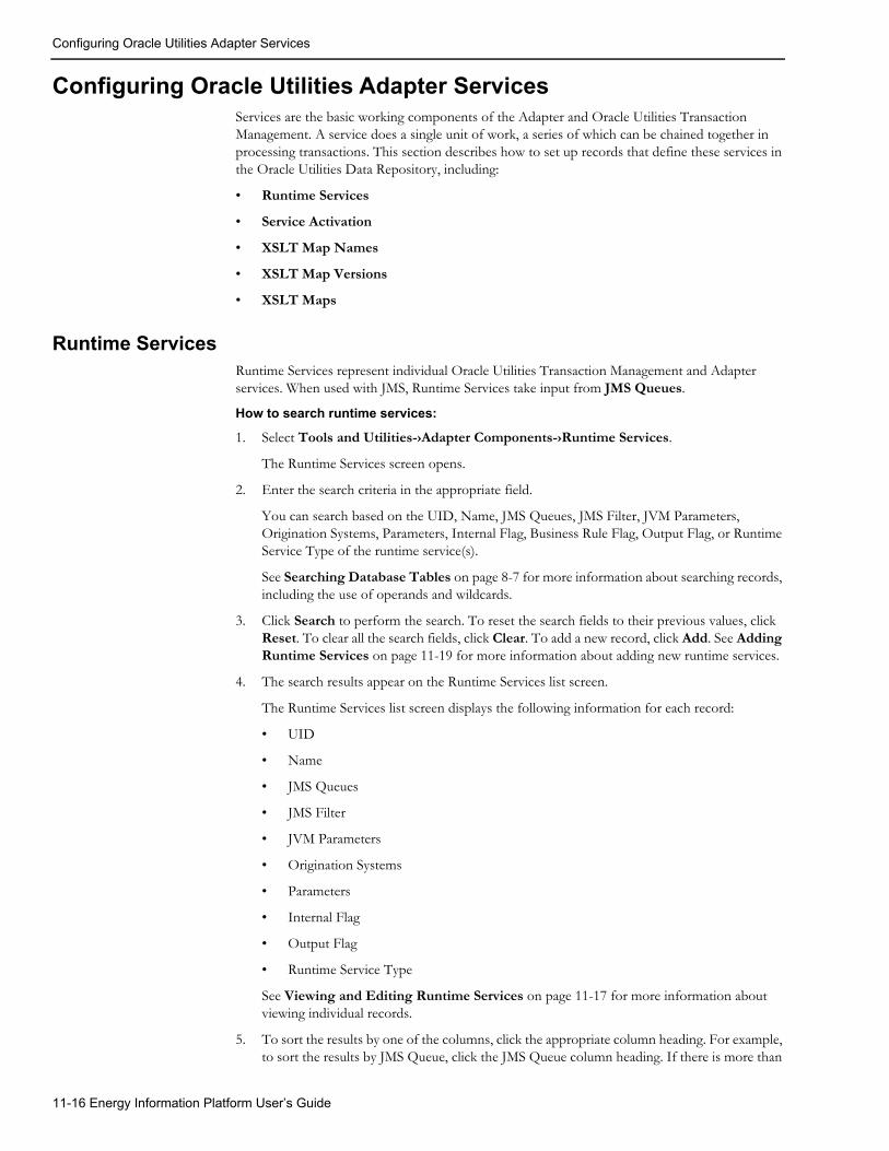
Configuring Oracle Utilities Adapter Services
Configuring Oracle Utilities Adapter ServicesServices are the basic working components of the Adapter and Oracle Utilities Transaction Management. A service does a single unit of work, a series of which can be chained together in processing transactions. This section describes how to set up records that define these services in the Oracle Utilities Data Repository, including:
• Runtime Services
• Service Activation
• XSLT Map Names
• XSLT Map Versions
• XSLT Maps
Runtime ServicesRuntime Services represent individual Oracle Utilities Transaction Management and Adapter services. When used with JMS, Runtime Services take input from JMS Queues.
How to search runtime services:
1. Select Tools and Utilities-›Adapter Components-›Runtime Services.
The Runtime Services screen opens.
2. Enter the search criteria in the appropriate field.
You can search based on the UID, Name, JMS Queues, JMS Filter, JVM Parameters, Origination Systems, Parameters, Internal Flag, Business Rule Flag, Output Flag, or Runtime Service Type of the runtime service(s).
See Searching Database Tables on page 8-7 for more information about searching records, including the use of operands and wildcards.
3. Click Search to perform the search. To reset the search fields to their previous values, click Reset. To clear all the search fields, click Clear. To add a new record, click Add. See Adding Runtime Services on page 11-19 for more information about adding new runtime services.
4. The search results appear on the Runtime Services list screen.
The Runtime Services list screen displays the following information for each record:
• UID
• Name
• JMS Queues
• JMS Filter
• JVM Parameters
• Origination Systems
• Parameters
• Internal Flag
• Output Flag
• Runtime Service Type
See Viewing and Editing Runtime Services on page 11-17 for more information about viewing individual records.
5. To sort the results by one of the columns, click the appropriate column heading. For example, to sort the results by JMS Queue, click the JMS Queue column heading. If there is more than
11-16 Energy Information Platform User’s Guide

Configuring Oracle Utilities Adapter Services
one page of results, you can move between pages using the and buttons. To change the number of results that appears on each page, enter the number in the Rows field.
6. To view a record, click on the corresponding [...] link. The selected record will appear in the Runtime Services screen. See Viewing and Editing Runtime Services on page 11-17 for more information.
7. To perform another search, click Search. To refresh the contents of the list screen, click the refresh icon.
8. Optional. To delete one or more records, check the check boxes corresponding to the records to be deleted, and click Delete. To clear all the checkboxes, click Clear.
9. Optional. To add a new record, click Add. See Adding Runtime Services on page 11-19 for more information about adding new runtime services.
Viewing and Editing Runtime ServicesIndividual runtime services are viewed on the Runtime Services screen. This screen opens when you select a record from the Runtime Services list screen.
How to view and edit runtime services:
1. Click on the [...] link for the runtime service you wish to view. The selected record opens in the Runtime Services screen.
The Runtime Services screen displays the following information for the selected record:
• UID: The unique identifier for the record in the Oracle Utilities Data Repository.
• Name: The identifier for the runtime service. Note: For runtime services of type “FPORTAL” (file portal), the name of the runtime service is used to create a working directory on the file system and must not contain any of the following characters: / \ : * ? " < > |.
• JMS Queues: The JMS queue that serves as input for the service. This is not applicable to all services.
• JMS Filter: Filtering syntax used to limit the messages that will be available to the service. This filter is a feature of JMS that allows the ability to filter messages with a SQL-like query. For more information on how this works, see the following URL:http://java.sun.com/j2ee/1.4/docs/tutorial/doc/JMS4.html#wp79145. If the service does not require filtering, this field will be empty.
• JVM Parameters: Additional parameters (see Parameters under System Properties on page 11-12) used by the JVM for the individual service. Most commonly this is used to add memory for processing large documents. For available options, see the following URL:http://java.sun.com/j2se/1.4.2/docs/tooldocs/windows/java.html.
• Origination Systems: The type of system the service is associated with. See Origination Systems on page 11-10 for more information about setting up origination systems.
• Parameters: Additional command line parameters to be applied to the service. The most common parameter is the “-qs” parameter, which controls the JMS queue to which the service will write. Services that use a JMS queue require a “-qs” parameter.
• Internal Flag: A flag that indicates (Y or N) whether or not the service is an “internal system.”
• Output Flag: A flag that indicates (Y or N) whether or not the service produces output. The only currently supported output service the Outbound Gateway.
• Runtime Service Type: The general class of service (from the Runtime Service Type table). For the Adapter, this should be one of the following:
Setting Up and Configuring the Energy Information Platform Adapter 11-17

Configuring Oracle Utilities Adapter Services
• FPORTAL: The Adapter File Loader Service. This service loads payloads from a file in a specified directory.
Note: Runtime services of type FPORTAL that monitor a network location cannot be run on more than one application server at the same time.
• QPORTAL: The Adapter Queue Loader Service. This service loads payloads from a specified JMS queue.
• DPORTAL: The Adapter Database Loader Service. This service loads payloads from the Payload Table in the Oracle Utilities Data Repository.
• MDMPORTAL: The MDM Web Transactions portal. This service executes operations performed by Oracle Utilities Meter Data Management users working with the application’s web-based user interface.
Note: At least one service of type MDMPORTAL must be running in order for users to use the Oracle Utilities Meter Data Management application via the web-based user interface.
Note: MDMPORTAL services are used ONLY by Oracle Utilities Meter Data Management.
• Properties: Properties associated with the service. Properties are defined in an XML structure. See Defining Service Properties for Adapter Runtime Services on page 11-28 for more information about Runtime Service Properties.
2. Edit data in the fields as appropriate. See Working with Data Types on page 8-4 for more information about editing data values.
When editing the Properties field, you can either edit the XML string in the text box, or upload an XML document that contains the properties in XML format. To upload a document, click Upload Rule Properties. The Properties text box is replaced by a text field.
Enter the path and file name of the document that contains the properties, or click the Browse button and select the appropriate file using the Choose File dialog. Click Cancel to restore the Properties text box. See the Oracle Utilities Energy Information Platform Configuration Guide for more information about creating properties for runtime services.
3. To save changes made to the record, click Save. To save the edited record as a new record, click Save As New.
Note: The Save As New option only works if the identity of the record has been changed.
4. To perform a new search, click Search.
5. To open a list of records, click List.
6. To delete the current record, click Delete.
7. To navigate from the current record to one of its parent or lookup records, click the Name of the parent table on the record. Parent and lookup records appear underlined on the screen. Use the Back button to return to the record being viewed.
8. To view a list of child records, click the name of the child table you wish to view in the Children section of the screen. Use the Back button to return to the record being viewed.
11-18 Energy Information Platform User’s Guide

Configuring Oracle Utilities Adapter Services
Adding Runtime ServicesYou can also add new runtime services.
How to add runtime services:
1. Click Add on either the Runtime Services search or list screens. A blank Runtime Services screen opens.
2. Enter the identifier for the service in the Name field. Note: For runtime services of type “FPORTAL” (file portal), the name of the runtime service is used to create a working directory on the file system and must not contain any of the following characters: / \ : * ? " < > |.
3. Select the JMS Queue by clicking the Browse button ( ). This opens a dialog window that lists all the available JMS queues. If a JMS queue is not applicable to the service, leave this blank.
4. Enter the filtering syntax used to limit the messages that will be available to the service in the JMS Filter field. This filter allows the ability to filter messages with a SQL-like query. For more information on how this works, see the following URL:http://java.sun.com/j2ee/1.4/docs/tutorial/doc/JMS4.html#wp79145. If the service does not require filtering, leave field empty.
5. Enter appropriate parameters for the JVM in the JVM Parameter field. For available options, see the following URL:http://java.sun.com/j2se/1.4.2/docs/tooldocs/windows/java.html.
6. Select the Origination Systems by clicking the Browse button ( ). This opens a dialog window that lists all the available origination systems.
7. Enter any additional command line parameters to be applied to the service in the Parameters field.
8. Specify whether or not the service is an “internal system” by entering either “Y” (Yes) or “N” (No) in the Internal Flag field. This should always be set to “Y” (Yes) for Adapter services (File Portal, Queue Portal, and Database Portal).
9. Specify whether or not the service produces output. in the Output Flag field. The only currently supported output service the Outbound Gateway. This should always be set to “N” (No) for Adapter services (File Portal, Queue Portal, and Database Portal).
10. Select the Runtime Service Type by clicking the Browse button ( ). This opens a dialog window that lists all the available runtime service types. For the Adapter, this should be one of the following:
• FPORTAL: The Adapter File Loader Service. This service loads payloads from a file in a specified directory.
Note: Runtime services of type FPORTAL that monitor a network location cannot be run on more than one application server at the same time.
• QPORTAL: The Adapter Queue Loader Service. This service loads payloads from a specified JMS queue.
• DPORTAL: The Adapter Database Loader Service. This service loads payloads from the Payload Table in the Oracle Utilities Data Repository.
• MDMPORTAL: The MDM Web Transactions portal. This service executes operations performed by Oracle Utilities Meter Data Management users working with the application’s web-based user interface.
Note: At least one service of type MDMPORTAL must be running in order for users to use the Oracle Utilities Meter Data Management application via the web-based user interface.
Setting Up and Configuring the Energy Information Platform Adapter 11-19

Configuring Oracle Utilities Adapter Services
Note: MDMPORTAL services are used ONLY by Oracle Utilities Meter Data Management.
11. Enter properties (in XML) for the service in the Properties field. You can either enter text manually (or copy/paste), or upload an XML document that contains the properties in XML format. To upload a document, click Upload Rule Properties. The Properties text box is replaced by a text field.
Enter the path and file name of the document that contains the properties, or click the Browse button and select the appropriate file using the Choose File dialog. Click Cancel to restore the Properties text box. See Defining Service Properties for Adapter Runtime Services on page 11-28 for more information about creating properties for runtime services.
12. To save the record, click Save. The new runtime service appears on the screen.
Service ActivationService Activation records define how individual Oracle Utilities Transaction Management and Adapter services will run on each server. Service Activation records link specific Servers to Runtime Services.
How to search service activation records:
1. Select Tools and Utilities-›Adapter Components-›Service Activation.
The Service Activation screen opens.
2. Enter the search criteria in the appropriate field.
You can search based on the Server, Runtime Services, Enabled flag, Run at Startup flag, or Keep Alive flag of the service activation record(s).
See Searching Database Tables on page 8-7 for more information about searching records, including the use of operands and wildcards.
3. Click Search to perform the search. To reset the search fields to their previous values, click Reset. To clear all the search fields, click Clear. To add a new record, click Add. See Adding Service Activation Records on page 11-21 for more information about adding new service activation records.
4. The search results appear on the Service Activation list screen.
The Service Activation list screen displays the following information for each record:
• Server
• Runtime Services
• Enabled
• Run at Startup
• Keep Alive
See Viewing and Editing Service Activation Records on page 11-21 for more information about viewing individual records.
5. To sort the results by one of the columns, click the appropriate column heading. For example, to sort the results by Server, click the Server column heading. If there is more than one page
of results, you can move between pages using the and buttons. To change the number of results that appears on each page, enter the number in the Rows field.
6. To view a record, click on the corresponding [...] link. The selected record will appear in the Service Activation screen. See Viewing and Editing Service Activation Records on page 11-21 for more information.
11-20 Energy Information Platform User’s Guide

Configuring Oracle Utilities Adapter Services
7. To perform another search, click Search. To refresh the contents of the list screen, click the refresh icon.
8. Optional. To delete one or more records, check the check boxes corresponding to the records to be deleted, and click Delete. To clear all the checkboxes, click Clear.
9. Optional. To add a new record, click Add. See Adding Service Activation Records on page 11-21 for more information about adding new service activation records.
Viewing and Editing Service Activation RecordsIndividual service activation records are viewed on the Service Activation screen. This screen opens when you select a record from the Service Activation list screen.
How to view and edit service activation records:
1. Click on the [...] link for the service activation record you wish to view. The selected record opens in the Service Activation screen.
The Service Activation screen displays the following information for the selected record:
• Server: The Server on which the service will run. See Servers on page 11-2 for more information about setting up servers.
• Runtime Services: The service to be run. See Runtime Services on page 11-16 for more information about setting up runtime services.
• Enabled: A flag that indicates (Yes or No) is the service is allowed to run on the server. Services must be enabled to run.
• Run at Startup: A flag that indicates (Yes or No) if the service will start as soon as the server starts.
• Keep Alive: A flag that indicates (Yes or No) whether or not the service will restart itself in the event it shuts down.
2. Edit data in the fields as appropriate. See Working with Data Types on page 8-4 for more information about editing data values.
3. To save changes made to the record, click Save. To save the edited record as a new record, click Save As New.
Note: The Save As New option only works if the identity of the record has been changed.
4. To perform a new search, click Search.
5. To open a list of records, click List.
6. To delete the current record, click Delete.
7. To navigate from the current record to one of its parent or lookup records, click the Name of the parent table on the record. Parent and lookup records appear underlined on the screen. Use the Back button to return to the record being viewed.
8. To view a list of child records, click the name of the child table you wish to view in the Children section of the screen. Use the Back button to return to the record being viewed.
Adding Service Activation RecordsYou can also add new service activation records.
How to add service activation records:
1. Click Add on either the Service Activation search or list screens. A blank Service Activation screen opens.
2. Select the Server by clicking the Browse button ( ). This opens a dialog window that lists all the available servers.
Setting Up and Configuring the Energy Information Platform Adapter 11-21

Configuring Oracle Utilities Adapter Services
3. Select the Runtime Services by clicking the Browse button ( ). This opens a dialog window that lists all the available runtime services.
4. Specify whether or not the service should be allowed to run on the server by selecting either “Yes” or “No” on the Enabled drop-down list.
5. Specify whether or not the service will start as soon as the server starts by selecting either “Yes” or “No” on the Run at Startup drop-down list.
6. Specify whether or not the service will restart itself in the event it shuts down by selecting either “Yes” or “No” on the Keep Alive drop-down list.
7. To save the record, click Save. The new service activation record appears on the screen.
XSLT Map NamesXSLT Map Names are names and descriptions of XML stylesheets (or maps) used by Oracle Utilities Transaction Management and the Adapter. XSLT Maps Names are used to define XSLT Map Versions.
How to search XSLT map names:
1. Select Tools and Utilities-›Adapter Components-›XSLT Map Names.
The XSLT Map Names screen opens.
2. Enter the search criteria in the appropriate field.
You can search based on the UID (unique identifier for the record in the Oracle Utilities Data Repository), Name, or Description of the map name(s).
See Searching Database Tables on page 8-7 for more information about searching records, including the use of operands and wildcards.
3. Click Search to perform the search. To reset the search fields to their previous values, click Reset. To clear all the search fields, click Clear. To add a new record, click Add. See Adding XSLT Map Names on page 11-23 for more information about adding new XSLT map names.
4. The search results appear on the XSLT Map Names list screen.
The XSLT Map Names list screen displays the following information for each record:
• UID
• Name
• Description
See Viewing and Editing XSLT Map Names on page 11-23 for more information about viewing individual records.
5. To sort the results by one of the columns, click the appropriate column heading. For example, to sort the results by Name, click the Name column heading. If there is more than one page
of results, you can move between pages using the and buttons. To change the number of results that appears on each page, enter the number in the Rows field.
6. To view a record, click on the corresponding [...] link. The selected record will appear in the XSLT Map Names screen. See Viewing and Editing XSLT Map Names on page 11-23 for more information.
7. To perform another search, click Search. To refresh the contents of the list screen, click the refresh icon.
8. Optional. To delete one or more records, check the check boxes corresponding to the records to be deleted, and click Delete. To clear all the checkboxes, click Clear.
11-22 Energy Information Platform User’s Guide

Configuring Oracle Utilities Adapter Services
9. Optional. To add a new record, click Add. See Adding XSLT Map Names on page 11-23 for more information about adding new XSLT map names.
Viewing and Editing XSLT Map NamesIndividual XSLT map names are viewed on the XSLT Map Names screen. This screen opens when you select a record from the XSLT Map Names list screen.
How to view and edit XSLT map names:
1. Click on the [...] link for the XSLT map name you wish to view. The selected record opens in the XSLT Map Names screen.
The XSLT Map Names screen displays the following information for the selected record:
• UID: The unique identifier for the record in the Oracle Utilities Data Repository.
• Name: The name of the XSLT map name.
• Description: A description of the XSLT map name.
2. Edit data in the fields as appropriate. See Working with Data Types on page 8-4 for more information about editing data values.
3. To save changes made to the record, click Save. To save the edited record as a new record, click Save As New.
Note: The Save As New option only works if the identity of the record has been changed.
4. To perform a new search, click Search.
5. To open a list of records, click List.
6. To delete the current record, click Delete.
7. To navigate from the current record to one of its parent or lookup records, click the Name of the parent table on the record. Parent and lookup records appear underlined on the screen. Use the Back button to return to the record being viewed.
8. To view a list of child records, click the name of the child table you wish to view in the Children section of the screen. Use the Back button to return to the record being viewed.
Adding XSLT Map NamesYou can also add new XSLT map names.
How to add XSLT map names:
1. Click Add on either the XSLT Map Names search or list screens. A blank XSLT Map Names screen opens.
2. Enter the name of the XSLT map name in the Name field.
3. Enter a description for the map in the Description field.
4. To save the record, click Save. The new map record appears on the screen.
XSLT Map VersionsXSLT Map Versions represent specific versions of XML stylesheets (or maps) used by Oracle Utilities Transaction Management and the Adapter. XSLT Maps Versions are used to define XSLT Maps.
How to search XSLT map versions:
1. Select Tools and Utilities-›Adapter Components-›XSLT Map Versions.
The XSLT Map Versions screen opens.
2. Enter the search criteria in the appropriate field.
Setting Up and Configuring the Energy Information Platform Adapter 11-23

Configuring Oracle Utilities Adapter Services
You can search based on the UID (unique identifier for the record in the Oracle Utilities Data Repository), XSLT Map Name, Description, Major Version, Minor Version, Begin Date, or End Date of the map version(s).
See Searching Database Tables on page 8-7 for more information about searching records, including the use of operands and wildcards.
3. Click Search to perform the search. To reset the search fields to their previous values, click Reset. To clear all the search fields, click Clear. To add a new record, click Add. See Adding XSLT Map Versions on page 11-25 for more information about adding new XSLT map versions.
4. The search results appear on the XSLT Map Versions list screen.
The XSLT Map Versions list screen displays the following information for each record:
• UID
• XSLT Map Name
• Description
• Major Version
• Minor Version
• Begin Date
• End Date
See Viewing and Editing XSLT Map Versions on page 11-24 for more information about viewing individual records.
5. To sort the results by one of the columns, click the appropriate column heading. For example, to sort the results by XSLT Map Name, click the XSLT Map Name column heading. If there
is more than one page of results, you can move between pages using the and buttons. To change the number of results that appears on each page, enter the number in the Rows field.
6. To view a record, click on the corresponding [...] link. The selected record will appear in the XSLT Map Versions screen. See Viewing and Editing XSLT Map Versions on page 11-24 for more information.
7. To perform another search, click Search. To refresh the contents of the list screen, click the refresh icon.
8. Optional. To delete one or more records, check the check boxes corresponding to the records to be deleted, and click Delete. To clear all the checkboxes, click Clear.
9. Optional. To add a new record, click Add. See Adding XSLT Map Versions on page 11-25 for more information about adding new XSLT map versions.
Viewing and Editing XSLT Map VersionsIndividual XSLT map versions are viewed on the XSLT Map Versions screen. This screen opens when you select a record from the XSLT Map Versions list screen.
How to view and edit XSLT map versions:
1. Click on the [...] link for the XSLT map name you wish to view. The selected record opens in the XSLT Map Versions screen.
The XSLT Map Versions screen displays the following information for the selected record:
• UID: The unique identifier for the record in the Oracle Utilities Data Repository.
11-24 Energy Information Platform User’s Guide

Configuring Oracle Utilities Adapter Services
• XSLT Map Name: The XSLT Map Name record associated with the XSLT map version. See XSLT Map Names on page 11-22 for more information about XSLT Map Names.
• Description: A description of the XSLT map version.
• Major Version: Major version number for the XSLT map version.
• Minor Version: Major version number for the XSLT map version.
• Begin Date: The date and time at which the XSLT map version goes into effect.
• End Date: The date and time after which the XSLT map version is no longer in effect.
2. Edit data in the fields as appropriate. See Working with Data Types on page 8-4 for more information about editing data values.
3. To save changes made to the record, click Save. To save the edited record as a new record, click Save As New.
Note: The Save As New option only works if the identity of the record has been changed.
4. To perform a new search, click Search.
5. To open a list of records, click List.
6. To delete the current record, click Delete.
7. To navigate from the current record to one of its parent or lookup records, click the Name of the parent table on the record. Parent and lookup records appear underlined on the screen. Use the Back button to return to the record being viewed.
8. To view a list of child records, click the name of the child table you wish to view in the Children section of the screen. Use the Back button to return to the record being viewed.
Adding XSLT Map VersionsYou can also add new XSLT map versions.
How to add XSLT map versions:
1. Click Add on either the XSLT Map Versions search or list screens. A blank XSLT Map Versions screen opens.
2. Enter the name of the XSLT map version in the Name field.
3. Select the appropriate XSLT Map Name for the map version by clicking the Browse button
( ). This opens a dialog window that lists all the available XSLT map names. See XSLT Map Names on page 11-22 for more information about setting up XSLT Map Names.
4. Enter a description for the map version in the Description field.
5. Enter the major version number for the map version in the Major Version field.
6. Enter the minor version number for the map version in the Minor Version field.
7. Enter the date and time at which the map version goes into effect in the Begin Date. You can enter the date either by typing the date manually or clicking the drop-down arrow to the right of the date field. This opens a calendar dialog that you can use to select the start date. You can enter the time either by typing the time manually, or by using the default time of 00:00:00. If appropriate, enter the date and time at which the map version is no longer in effect in the End Date field in the same manner.
8. To save the record, click Save. The new map version record appears on the screen.
Setting Up and Configuring the Energy Information Platform Adapter 11-25

Configuring Oracle Utilities Adapter Services
XSLT MapsXSLT Maps are records which store the actual XML stylesheets (or maps) used by Oracle Utilities Transaction Management and the Adapter. XSLT Maps are defined by XSLT Map Versions.
How to search XSLT maps:
1. Select Tools and Utilities-›Adapter Components-›XSLT Maps.
The XSLT Maps screen opens.
2. Enter the search criteria in the appropriate field.
You can search based on the UID (unique identifier for the record in the Oracle Utilities Data Repository) or XSLT Map Version of the map(s).
See Searching Database Tables on page 8-7 for more information about searching records, including the use of operands and wildcards.
3. Click Search to perform the search. To reset the search fields to their previous values, click Reset. To clear all the search fields, click Clear. To add a new record, click Add. See Adding XSLT Maps on page 11-27 for more information about adding new XSLT maps.
4. The search results appear on the XSLT Maps list screen.
The XSLT Maps list screen displays the following information for each record:
• UID
• XSLT Map Version
See Viewing and Editing XSLT Maps on page 11-26 for more information about viewing individual records.
5. To sort the results by one of the columns, click the appropriate column heading. For example, to sort the results by XSLT Map Version, click the XSLT Map Version column heading. If
there is more than one page of results, you can move between pages using the and buttons. To change the number of results that appears on each page, enter the number in the Rows field.
6. To view a record, click on the corresponding [...] link. The selected record will appear in the XSLT Maps screen. See Viewing and Editing XSLT Maps on page 11-26 for more information.
7. To perform another search, click Search. To refresh the contents of the list screen, click the refresh icon.
8. Optional. To delete one or more records, check the check boxes corresponding to the records to be deleted, and click Delete. To clear all the checkboxes, click Clear.
9. Optional. To add a new record, click Add. See Adding XSLT Maps on page 11-27 for more information about adding new XSLT maps.
Viewing and Editing XSLT MapsIndividual XSLT maps are viewed on the XSLT Maps screen. This screen opens when you select a record from the XSLT Maps list screen.
How to view and edit XSLT maps:
1. Click on the [...] link for the XSLT map you wish to view. The selected record opens in the XSLT Maps screen.
The XSLT Maps screen displays the following information for the selected record:
• UID: The unique identifier for the record in the Oracle Utilities Data Repository.
• XSLT Map Version: The XSLT Map Version record associated with the XSLT map. See XSLT Map Versions on page 11-23 for more information about XSLT Map Versions.
11-26 Energy Information Platform User’s Guide

Configuring Oracle Utilities Adapter Services
• XML Map: The XML map.
2. Edit data in the fields as appropriate. See Working with Data Types on page 8-4 for more information about editing data values.
When editing the XML Map field, you can either edit the XML string in the text box, or upload an XML document that contains the XML map. To upload a document, click Upload an XSLT. The XML Map text box is replaced by a text field.
Enter the path and file name of the document that contains the map, or click the Browse button and select the appropriate file using the Choose File dialog. Click Cancel to restore the XML Map text box. See the Oracle Utilities Energy Information Platform Configuration Guide for more information about creating XML maps.
3. To save changes made to the record, click Save. To save the edited record as a new record, click Save As New.
Note: The Save As New option only works if the identity of the record has been changed.
4. To perform a new search, click Search.
5. To open a list of records, click List.
6. To delete the current record, click Delete.
7. To navigate from the current record to one of its parent or lookup records, click the Name of the parent table on the record. Parent and lookup records appear underlined on the screen. Use the Back button to return to the record being viewed.
8. To view a list of child records, click the name of the child table you wish to view in the Children section of the screen. Use the Back button to return to the record being viewed.
Adding XSLT MapsYou can also add new XSLT maps.
How to add XSLT maps:
1. Click Add on either the XSLT Maps search or list screens. A blank XSLT Maps screen opens.
2. Select the appropriate XSLT Map Version for the map by clicking the Browse button ( ). This opens a dialog window that lists all the available XSLT map names. See XSLT Map Versions on page 11-23 for more information about setting up XSLT Map Versions.
3. Enter the XML map in the XML Map field. You can either enter text manually (or copy/paste), or upload an XML document that contains the map. To upload a document, click Upload am XSLT. The XML Map text box is replaced by a text field.
Enter the path and file name of the document that contains the map, or click the Browse button and select the appropriate file using the Choose File dialog. Click Cancel to restore the XML Map text box. See the Oracle Utilities Energy Information Platform Configuration Guide for more information about creating XML maps.
4. To save the record, click Save. The new map record appears on the screen.
Setting Up and Configuring the Energy Information Platform Adapter 11-27

Defining Service Properties for Adapter Runtime Services
Defining Service Properties for Adapter Runtime ServicesService Properties define how Adapter Runtime Services function during runtime. Service properties are used to associate a business rule to a service property, to specify the data source(s) that the service will interact with, to specify how the service creates output based on exceptions, and other properties.
This section describes Service Properties used by Adapter Runtime Services, including:
• Properties Format
• Common Properties
• File Portal Properties
• Database Portal Properties
• Sample Properties
Properties FormatAdapter services are defined in the Runtime Service table in the Oracle Utilities Data Repository. The Properties column in this table defines specific properties expected and/or required by the service. This column should contain an XML string listing the properties used by the service.
The Properties XML string should be in the following form:
<PROPERTIES><PROPERTY NAME="PropertyName1" VALUE="PropertyValue1"/><PROPERTY NAME="PropertyName2" VALUE="PropertyValue2"/>...
</PROPERTIES>
Element DescriptionsEach of the data elements used by this structure are described below.
Elements:
• PROPERTIES: Root element that contains one or more PROPERTY elements.
• PROPERTY: Element that defines a specific Property used by the service.
Attributes:
• NAME: The name of the Property.
• VALUE: The value for the Property.
Names and appropriate values for each property are listed in the descriptions below.
Property DescriptionsEach of the properties used by the services are described in the following format:
NAME: The name of the Property.
• Required: Is the Property required?
• Possible Values: Possible values for the Property.
• Description: A description of the Property.
• Default Value: The default value for the Property.
• Example: An example of the Property.
11-28 Energy Information Platform User’s Guide

Defining Service Properties for Adapter Runtime Services
Common PropertiesAll Adapter Runtime Services can use the following Properties, including:
• General Properties
• Data Source Properties
• Output Properties
• Exception Output Properties
• Work Queue Properties
General PropertiesGeneral properties define general attributes of the service.
STORAGE_LEVEL• Required: No
• Possible Values: 0,1, or 2
• Description: Optional parameter that controls how much data will be stored in the database. Valid values are:
• 0 - No storage
• 1 - Data is saved in its raw format
• 2 - Data is saved in its raw format and again after all input data conversions have been performed (but before any call to the RDL engine).
• Default Value: 1
• Example:
<PROPERTY NAME="STORAGE_LEVEL" VALUE="2"/>
DC_DELIMITER• Required: No
• Possible Values: Any string or character
• Description: Optional parameter that specifies an alternative character to use as a delimiter in the DataConverter property lists. Note that this property applies to all DataConverter property listings. Specify “\t” for the Tab character.
• Default Value: “,”
• Example:
<PROPERTY NAME="DC_DELIMITER" VALUE="|"/>
MAX_ERRORS• Required: No
• Possible Values: Any integer
• Description: Optional parameter that limits the number of exceptions logged to the Inbound Exception table.
• Default Value: None
• Example:
<PROPERTY NAME="MAX_ERRORS" VALUE="10"/>
Setting Up and Configuring the Energy Information Platform Adapter 11-29

Defining Service Properties for Adapter Runtime Services
INPUT_DC_ 0 (INPUT_DC_1, ..., INPUT_DC_n)• Required: No
• Possible Values: Any valid DataConverter class name with appropriate parameters, separated with the value specified by the DC_DELIMITER property.
• Description: Optional parameter specifying the full class name of a DataConverter to use in the data input phase. Further parameters are dependent on the type of DataConverter required and should also be listed in the value attribute delimited by commas or the character specified in the DC_DELIMITER property. Note that parameters must be specified in the order expected by the particular DataConverter. Multiple DataConverters can be "chained" together by listing each class in a separate service property with the desired ordinal number appended to the property name. When listing multiple converters, the first must be “0”.
• Default Value: None
• Example:
<PROPERTY NAME="INPUT_DC_0" VALUE="com.lodestarcorp.core.xml.parsers.RowIdentifyingCSVParser"/>
<PROPERTY NAME="INPUT_DC_1" VALUE="com.lodestarcorp.portal.data.XSLConverter,C:\Interval\CSVMap.xslt"/>
...
<PROPERTY NAME="INPUT_DC_14" VALUE="com.lodestarcorp.portal.data.SchemaValidator,C:\Interval\ IntdUsage.xsd"/>
CONVERTER_TIMEOUT• Required: No
• Possible Values: Any positive integer
• Description: A diagnostic property for detecting deadlocks in data converters. The value of this property is the number of seconds the system will wait for a data converter to finish processing a payload.
• Default Value: 0
• Example:
<PROPERTY NAME="CONVERTER_TIMEOUE" VALUE="600"/>
RULE_NAME• Required: No
• Possible Values: Any valid RDL name
• Description: Optional parameter that specifies the name of the Business Rule that should be run. If this parameter is not specified, no RDL processing will occur.
• Default Value: None
• Example:
<PROPERTY NAME="RULE_NAME" VALUE="UsageRule"/>
RDL_MEMORY_BUFFER_SIZE• Required: No
• Possible Values: An integer value that will not exceed available memory.
• Description: Optional parameter that indicates how much memory should be allocated to the incoming payload prior to RDL processing. If the payload is larger than the set amount, it will be written to a temporary file on the disk.
11-30 Energy Information Platform User’s Guide

Defining Service Properties for Adapter Runtime Services
• Default Value: 5 (MB)
• Example:
<PROPERTY NAME="RDL_MEMORY_BUFFER_SIZE" VALUE="3"/>
Data Source PropertiesData source properties define the data source(s) used by the Runtime Service, including the default data source, as well as optional RDL-specific data sources.
DEFAULT_DSN• Required: No
• Possible Values: Any valid DSN
• Description: The name of an ODBC data source that can be used as a default for other parameters such as the RDL_DSNn parameters or the WQ_DSN parameter.
• Default Value: None
• Example:
<PROPERTY NAME="DEFAULT_DSN" VALUE="MyDB"/>
DEFAULT_DDBQUALIFIER• Required: No
• Possible Values: Any valid database qualifier
• Description: A default qualifier that can be used in place of other parameters such as the RDL_DDBQUALIFIER_1 and the WQ_DDBQUALIFIER.
• Default Value: None
• Example:
<PROPERTY NAME="DEFAULT_DBQUALIFIER" VALUE="QualName"/>
DEFAULT_USER• Required: No
• Possible Values: Any valid user ID
• Description: A default for the database user. This parameter can be used in place of other parameters such as the RDL_USER_1 and WQ_USER parameters.
• Default Value: None
• Example:
<PROPERTY NAME="DEFAULT_USER" VALUE="UserName"/>
Setting Up and Configuring the Energy Information Platform Adapter 11-31

Defining Service Properties for Adapter Runtime Services
DEFAULT_PASSWORD• Required: No
• Possible Values: Any valid user password
• Description: A default for the database password. This parameter can be used in place of other parameters such as the RDL_PASSWORD_1 and WQ_PASSWORD parameters.
• Default Value: None
• Example:
<PROPERTY NAME="DEFAULT_PASSWORD" VALUE="somePassword"/>
DEFAULT_DATASOURCE• Required: No
• Possible Values: A server name or IP address
• Description: When using an OLEDB connection, this parameter specifies the database server.
• Default Value: None
• Example:
<PROPERTY NAME="DEFAULT_DATASOURCE" VALUE="MDM105"/>
DEFAULT_USERNAME• Required: No
• Possible Values: Any valid web user ID. This value is case-sensitive.
• Description: A web user ID from Security Administration. It is used with the DEFAULT_PWD property for accessing the Oracle Utilities Data Repository. The default datasource that is configured in the security database is used as the database connection. The DEFAULT-x parameters apply to both Work Queue and Adapter operations. These parameters supersede all properties where the database connection is explicitly specified, such as RDL_DSN_1, WQ_DSN, and DEFAULT_DSN.
• Default Value: None
• Example:
<PROPERTY NAME="DEFAULT_USERNAME" VALUE="UserName"/>
DEFAULT_PWD• Required: No
• Possible Values: Any valid user password. This value is case-sensitive.
• Description: A password for a web user from Security Administration. Used with the DEFAULT_USERNAME property for accessing the Oracle Utilities Data Repository. The default datasource that is configured in the security database is used to establish the connection. The DEFAULT-x parameters apply to both Work Queue and Adapter operations. These parameters supersede all properties where the database connection is explicitly specified, such as RDL_DSN_1, WQ_DSN, and DEFAULT_DSN.
• Default Value: None
• Example:
<PROPERTY NAME="DEFAULT_PWD" VALUE="somePassword"/>
11-32 Energy Information Platform User’s Guide

Defining Service Properties for Adapter Runtime Services
DEFAULT_ALTERNATE_DATASOURCE• Required: No
• Possible Values: Any data source name
• Description: Optional parameter used in conjunction with DEFAULT_USERNAME and DEFAULT_PWD to provide a secondary connection beyond the default datasource to those applications that may require it. The DEFAULT-x parameters apply to both Work Queue and Adapter operations. These parameters supersede all properties where the database connection is explicitly specified, such as RDL_DSN_1, WQ_DSN, and DEFAULT_DSN.
• Default Value: None
• Example:
<PROPERTY NAME="DEFAULT_ALTERNATE_DATASOURCE" VALUE="MDM105"/>
ADAPTER_USERNAME• Required: No
• Possible Values: Any valid web user ID. This value is case-sensitive.
• Description: A web user ID from Security Administration. It is used with the ADAPTER_PWD property for accessing the Oracle Utilities Data Repository. The default datasource that is configured in the security database is used as the database connection. These parameters supersede all RDL_x_1 and RDL_x_2 properties.
• Default Value: None
• Example:
<PROPERTY NAME="ADAPTER_USERNAME" VALUE="UserName"/>
ADAPTER_PWD• Required: No
• Possible Values: Any valid user password. This value is case-sensitive.
• Description: A password for a web user from Security Administration. Used with the ADAPTER_USERNAME property for accessing the Oracle Utilities Data Repository. The default datasource that is configured in the security database is used to establish the connection. These parameters supersede all RDL_x_1 and RDL_x_2 properties.
• Default Value: None
• Example:
<PROPERTY NAME="ADAPTER_PWD" VALUE="somePassword"/>
ADAPTER_ALTERNATE_DATASOURCE• Required: No
• Possible Values: Any data source name
• Description: Optional parameter used in conjunction with ADAPTER_USERNAME and ADAPTER_PWD to provide a secondary connection beyond the default datasource to those applications that may require it. This parameter supersedes all and RDL_x_2 properties.
• Default Value: None
• Example:
<PROPERTY NAME="ADAPTER_ALTERNATE_DATASOURCE" VALUE="MDM105"/>
Setting Up and Configuring the Energy Information Platform Adapter 11-33

Defining Service Properties for Adapter Runtime Services
RDL_DSN_1• Required: Conditional
• Possible Values: Any valid DSN
• Description: The name of the primary ODBC data source that the RDL Engine should use. This property controls the database location from which RDL rules will be acquired and, if not overridden by RDL_DSN_2, the location on which the RDL will operate. Either this parameter or DEFAULT_DSN is required if the RULE_NAME property is specified.
• Default Value: None
• Example:
<PROPERTY NAME="RDL_DSN_1" VALUE="MyDB"/>
RDL_DDBQUALIFIER_1• Required: Conditional
• Possible Values: Any valid database qualifier
• Description: The primary qualifier for the database for the RDL process used to determine where the RDL rules will be acquired. Either this parameter or DEFAULT_DDBQUALIFIER is required if the RULE_NAME is specified.
• Default Value: None
• Example:
<PROPERTY NAME="RDL_DBQUALIFIER_1" VALUE="QualName"/>
RDL_USER_1• Required: Conditional
• Possible Values: Any valid user ID
• Description: The primary database user for the RDL process that will determine the access privileges of the RDL operations. Either this parameter or DEFAULT_USER is required if the RULE_NAME is specified.
• Default Value: None
• Example:
<PROPERTY NAME="RDL_USER_1" VALUE="UserName"/>
RDL_PASSWORD_1• Required: Conditional
• Possible Values: Any valid user password
• Description: The primary database user's password. This will determine the privileges in effect for the RDL operations. Either this parameter or the DEFAULT_PASSWORD is required if the RULE_NAME is specified.
• Default Value: None
• Example:
<PROPERTY NAME="RDL_PASSWORD_1" VALUE="somePassword"/>
RDL_DATASOURCE_1• Required: No
• Possible Values: A server name or IP address
• Description: When using an OLEDB connection, this parameter specifies the database server.
11-34 Energy Information Platform User’s Guide

Defining Service Properties for Adapter Runtime Services
• Default Value: None
• Example:
<PROPERTY NAME="RDL_DATASOURCE_1" VALUE="MDM105"/>
RDL_DSN_2• Required: No
• Possible Values: Any valid DSN
• Description: The name of the secondary ODBC data source that the RDL Engine should use. This property can provide an alternate database location on which the RDL will operate.
• Default Value: RDL_DSN_1 (which could be DEFAULT_DSN)
• Example:
<PROPERTY NAME="RDL_DSN_2" VALUE="MyOtherDB"/>
RDL_DDBQUALIFIER_2• Required: No
• Possible Values: Any valid database qualifier
• Description: The secondary qualifier for the database for the RDL process. This can override RDL_DDBQUALIFIER_1 to provide an alternate location on which the RDL will operate.
• Default Value: RDL_DDBQUALIFIER_1 (which could be DEFAULT_DDBQUALIFIER)
• Example:
<PROPERTY NAME="RDL_DBQUALIFIER_2" VALUE="QualName"/>
RDL_USER_2• Required: No
• Possible Values: Any valid user ID
• Description: The secondary database user overriding RDL_USER_1. This can supply an alternate login for the database location on which the RDL will operate.
• Default Value: RDL_USER_1 (which could be DEFAULT_USER)
• Example:
<PROPERTY NAME="RDL_USER_2" VALUE="UserName"/>
RDL_PASSWORD_2• Required: No
• Possible Values: Any valid user password
• Description: The secondary database user's password overriding RDL_PASSWORD_1. This can supply an alternate login for locating RDL rules.
• Default Value: RDL_PASSWORD_1 (which could be DEFAULT_PASSWORD)
• Example:
<PROPERTY NAME="RDL_PASSWORD_2" VALUE="somePassword"/>
RDL_DATASOURCE_2• Required: No
• Possible Values: A server name or IP address
Setting Up and Configuring the Energy Information Platform Adapter 11-35

Defining Service Properties for Adapter Runtime Services
• Description: When using an OLEDB connection, this parameter specifies the database server.
• Default Value: None
• Example:
<PROPERTY NAME="RDL_DATASOURCE_2" VALUE="MDM105"/>
Output PropertiesOutput properties define how services create output, including how services uses data converters and details of the output mechanism used by the service.
OUTPUT_DC_ 0 (OUTPUT_DC_1, ..., OUTPUT_DC_n)• Required: No
• Possible Values: Any valid DataConverter class name with appropriate parameters, separated with the value specified by the DC_DELIMITER property.
• Description: Optional parameter specifying the full class name of the DataConverter to use in the data output phase for non-exceptional data. The source for this output will be either the XML that is the source for the RDLEngine or the “streamed” instruction set that can be optionally produced by the RDL. Further parameters are dependent on the type of DataConverter required and should also be listed in the value attribute delimited by commas or the character specified in the DC_DELIMITER property. Note that parameters must be specified in the order expected by the particular DataConverter. Output will be produced only when this parameter is specified. Multiple DataConverters can be "chained" together by listing each class in a separate service property with the desired ordinal number appended to the property name. When listing multiple converters, the first must be “0”.
• Default Value: None
• Example:
<PROPERTY NAME="OUTPUT_DC_0" VALUE="com.lodestarcorp.portal.data.XSLConverter,C:\Interval\OutMap.xslt"/>
<PROPERTY NAME="OUTPUT_DC_1" VALUE="com.user.convert.Custom,extra info1,extra info2"/>
...
<PROPERTY NAME="OUTPUT_DC_14" VALUE="com.lodestarcorp.portal.data.SchemaValidator,C:\Interval\IntUsage.xsd"/>
OUTPUT_MECHANISM• Required: No
• Possible Values: Q, F, or D
• Description: Optional parameter for writing the outgoing data to an external target. The value can be “F” (File), “Q” (Queue), or “D” (Database). No output will be produced when this parameter is not provided. If a JMS-compliant messaging system is not available, “Q” is not allowed. If set to “D”, output is inserted into the Payload Extension table (ICEPAYLOADEXT).
• Default Value: None
• Example:
<PROPERTY NAME="OUTPUT_MECHANISM" VALUE="F"/>
11-36 Energy Information Platform User’s Guide

Defining Service Properties for Adapter Runtime Services
OUTPUT_FILE_DIR• Required: Conditional
• Possible Values: A location on disk (either absolute or relative path to the C:\LODESTAR\LTMH\Runtime directory)
• Description: Specifies the directory to which the Adapter will write output. Required if OUTPUT_MECHANISM is set to “F”.
Note: If specifying a directory on a mapped network drive via a UNC naming convention (\\<server>\<directory>), the IIS user (the default is IUSER_<machine_name>) must have valid permissions for the mapped drive.
• Default Value: None
• Example:
<PROPERTY NAME="OUTPUT_FILE_DIR" VALUE="C:\Out\Data"/>
OUTPUT_FILE_PREFIX• Required: No
• Possible Values: Any string (subject to operating system file name restrictions)
• Description: Optional parameter used in conjunction with OUTPUT_MECHANISM being set to “F”, that provides a prefix to prepend to the names of outputted files. If less than three characters, it will be padded.
• Default Value: out_
• Example:
<PROPERTY NAME="OUTPUT_FILE_PREFIX" VALUE="adapter"/>
OUTPUT_FILE_SUFFIX• Required: No
• Possible Values: Any string
• Description: Optional parameter used in conjunction with OUTPUT_MECHANISM being set to “F” that provides a suffix to append to the names of outputted files.
• Default Value: None
• Example:
<PROPERTY NAME="OUTPUT_FILE_SUFFIX" VALUE=".xml"/>
OUTPUT_QUEUE• Required: No
• Possible Values: Any valid queue name
• Description: Optional parameter used in conjunction with OUTPUT_MECHANISM being set to “Q”. Specifies the name of the queue to which to write. If not specified, the queue is specified by the “-qs” service parameter in the Parameters field of the Runtime Service record for the service.
• Default Value: None
• Example:
<PROPERTY NAME="OUTPUT_QUEUE" VALUE="QADAPTER"/>
Setting Up and Configuring the Energy Information Platform Adapter 11-37

Defining Service Properties for Adapter Runtime Services
OUTPUT_QUEUE_MSGTYPE• Required: No
• Possible Values: T or B
• Description: Optional parameter specifying whether to write text or byte messages to the queue when OUTPUT_MECHANISM is set to “Q”. Valid entries are “T” (text) or “B” (byte).
• Default Value: B
• Example:
<PROPERTY NAME="OUTPUT_QUEUE_MSGTYPE" VALUE="T"/>
OUTPUT_DATABASE_PAYLOADTYPE• Required: Conditional
• Possible Values: Any string
• Description: When OUTPUT_MECHANISM = “D,” this parameter specifies the Payload Type in the Payload Type column of the Payload Extension table (ICEPAYLOADEXT). Required if OUTPUT_MECHANISM is set to “D”.
• Default Value: MDM
• Example:
<PROPERTY NAME="OUTPUT_DATABASE_PAYLOADTYPE" VALUE="METERREAD"/>
OUTPUT_DIVIDING_STRING• Required: No
• Possible Values: A series of XML Element names separated by vertical pipe characters (“|”). The series should start with a pipe and end with an element name.
• Description: A mechanism to separate large XML files into smaller ones. This is used with an outputter to write pieces of the original input data to files, JMS queues, or the database.
• Default Value: None
• Example:
<PROPERTY NAME="OUTPUT_DIVIDING_STRING" VALUE="|METERREADS|METERREAD"/>
OUTPUT_ENCODING• Required: No
• Possible Values: A character set name (such as UTF-8)
• Description: A mechanism to allows payload splits with the OUTPUT_DIVIDING_STRING property to be written in a specified character set.
• Default Value: UTF-8
• Example:
<PROPERTY NAME="OUTPUT_ENCODING" VALUE="UTF-16"/>
OUTPUT_DIVIDING_XPATH• Required: No
• Possible Values: A valid Xpath string
• Description: A nodeset formed from the evaluation of the provided Xpath creates one or more new payloads. These are sent to an outputter and exported as new files, JMS messages, or database records. Namespace prefixes are defined with the OUTPUT_NAMESPACES property.
11-38 Energy Information Platform User’s Guide

Defining Service Properties for Adapter Runtime Services
• Default Value: None
• Example:
<PROPERTY NAME="OUTPUT_DIVIDING_XPATH" VALUE="//METERREADS/METERREAD/"/>
OUTPUT_NAME_COUNT• Required: No
• Possible Values: A positive integer
• Description: A parameter that may be used in conjunction with the OUTPUT_DIVIDING_STRING to group sets of elements together in a single output document. It represents the number of elements that should be grouped under a common parent node.
• Default Value: None
• Example:
<PROPERTY NAME="OUTPUT_NAME_COUNT" VALUE="10"/>
OUTPUT_NAMESPACES• Required: No
• Possible Values: Space separated string in the form prefix=namespace. The default namespace can be specified with a URI.
• Description: A set of space-separated namespace entries can be used to define them for the program. Used if namespace prefixes are required in the OUTPUT_DIVIDING_XPATH property,
• Default Value: None
• Example:
<PROPERTY NAME="OUTPUT_NAMESPACES" VALUE="http://default.ns cust=http://custom.ns"/>
Exception Output PropertiesException output properties define how services generate exception output, including data converters and details of the exception output mechanism used by the service.
EXCEPTION_OUTPUT_DC_ 0 (EXCEPTION_OUTPUT_DC_1, ..., EXCEPTION_OUTPUT_D-C_n)
• Required: No
• Possible Values: Any valid DataConverter class name with appropriate parameters, separated with the value specified by the DC_DELIMITER property.
• Description: Optional parameter specifying the full class name of the DataConverter to use in the data output phase for exceptions data. The source for this output will be the XML that is the source for the RDL Engine, but this output will only be produced when an exception occurs within the RDL. Further parameters are dependent on the type of DataConverter required and should also be listed in the value attribute delimited by commas or the character specified in the DC_DELIMITER property. Note that parameters must be specified in the order expected by the particular DataConverter. Exception output will be produced only when this parameter is specified. Multiple DataConverters can be "chained" together by listing each class in a separate service property with the desired ordinal number appended to the property name. When listing multiple converters, the first must be “0”.
• Default Value: None
• Example:
Setting Up and Configuring the Energy Information Platform Adapter 11-39

Defining Service Properties for Adapter Runtime Services
<PROPERTY NAME="EXCEPTION_OUTPUT_DC_0" VALUE="com.lodestarcorp.portal.data.XSLConverter,C:\Interval\ExMap.xslt"/>
<PROPERTY NAME="EXCEPTION_OUTPUT_DC_1" VALUE="com.user.convert.Custom,extra info1,extra info2"/>
...
<PROPERTY NAME="EXCEPTION_OUTPUT_DC_14" VALUE="com.lodestarcorp.portal.data.SchemaValidator,C:\Interval\ExIntUsage.xsd"/>
EXCEPTION_OUTPUT_MECHANISM• Required: No
• Possible Values: Q or F
• Possible Values: Q, F, or D
• Description: Optional parameter for writing the outgoing exception data to an external target. The value can be “F” (File), “Q” (Queue), or “D” (Database). No output will be produced when this parameter is not provided. If a JMS-compliant messaging system is not available, “Q” is not allowed. If set to “D”, exception output is inserted into the Payload Extension table (ICEPAYLOADEXT).
• Default Value: None
• Example:
<PROPERTY NAME="EXCEPTION_OUTPUT_MECHANISM" VALUE="F"/>
EXCEPTION_OUTPUT_FILE_DIR• Required: Conditional
• Possible Values: A location on disk (either absolute or relative path to the C:\LODESTAR\LTMH\Runtime directory)
• Description: Specifies the directory to which to write output. Required if EXCEPTION_OUTPUT_MECHANISM is set to “F”.
Note: If specifying a directory on a mapped network drive via a UNC naming convention (\\<server>\<directory>), the IIS user (the default is IUSER_<machine_name>) must have valid permissions for the mapped drive.
• Default Value: None
• Example:
<PROPERTY NAME="EXCEPTION_OUTPUT_FILE_DIR" VALUE="C:\Out\Errors"/>
EXCEPTION_OUTPUT_FILE_PREFIX• Required: No
• Possible Values: Any string (subject to operating system file name restrictions)
• Description: Optional parameter used in conjunction with EXCEPTION_OUTPUT_MECHANISM being set to “F”, that provides a prefix to prepend to the names of outputted files. If less than three characters, it will be padded.
• Default Value: out_
• Example:
<PROPERTY NAME="EXCEPTION_OUTPUT_FILE_PREFIX" VALUE="ERR_"/>
11-40 Energy Information Platform User’s Guide

Defining Service Properties for Adapter Runtime Services
EXCEPTION_OUTPUT_FILE_SUFFIX• Required: No
• Possible Values: Any string
• Description: Optional parameter used in conjunction with EXCEPTION_OUTPUT_MECHANISM being set to “F” that provides a suffix to append to the names of outputted files.
• Default Value: None
• Example:
<PROPERTY NAME="EXCEPTION_OUTPUT_FILE_SUFFIX" VALUE=".xml"/>
EXCEPTION_OUTPUT_QUEUE• Required: No
• Possible Values: Any valid queue name
• Description: Optional parameter used in conjunction with EXCEPTION_OUTPUT_MECHANISM being set to “Q”. Specifies the name of the queue to which to write. If not specified, the queue is specified by the “-qs” service parameter in the Parameters field of the Runtime Service record for the service.
• Default Value: None
• Example:
<PROPERTY NAME="EXCEPTION_OUTPUT_QUEUE" VALUE="QADAPTEREX"/>
EXCEPTION_OUTPUT_QUEUE_MSGTYPE• Required: No
• Possible Values: T or B
• Description: Optional parameter specifying whether to write text or byte messages to the queue when the EXCEPTION_OUTPUT_MECHANISM is set to “Q”. Valid entries are “T” (text) or “B” (byte).
• Default Value: B
• Example:
<PROPERTY NAME="EXCEPTION_OUTPUT_QUEUE_MSGTYPE" VALUE="T"/>
EXCEPTION_OUTPUT_DATABASE_PAYLOADTYPE• Required: Conditional
• Possible Values: Any string
• Description: When EXCEPTION_OUTPUT_MECHANISM = “D,” this parameter specifies the Payload Type in the Payload Type column of the Payload Extension table (ICEPAYLOADEXT). Required if EXCEPTION_OUTPUT_MECHANISM is set to “D”.
• Default Value: MDM
• Example:
<PROPERTY NAME="EXCEPTION_OUTPUT_DATABASE_PAYLOADTYPE" VALUE="METERREAD"/>
EXCEPTION_OUTPUT_DIVIDING_STRING• Required: No
• Possible Values: A series of XML Element names separated by vertical pipe characters (“|”). The series should start with a pipe and end with an element name.
Setting Up and Configuring the Energy Information Platform Adapter 11-41

Defining Service Properties for Adapter Runtime Services
• Description: A mechanism to separate large XML files into smaller ones. This is used with an outputter to write pieces of the original input data to files, JMS queues, or the database.
• Default Value: None
• Example:
<PROPERTY NAME="EXCEPTION_OUTPUT_DIVIDING_STRING VALUE="|METERREADS|METERREAD"/>
EXCEPTION_OUTPUT_ENCODING• Required: No
• Possible Values: A character set name (such as UTF-8)
• Description: A mechanism to allows payload splits with the EXCEPTION_OUTPUT_DIVIDING_STRING property to be written in a specified character set.
• Default Value: UTF-8
• Example:
<PROPERTY NAME="EXCEPTION_OUTPUT_ENCODING" VALUE="UTF-16"/>
EXCEPTION_OUTPUT_DIVIDING_XPATH• Required: No
• Possible Values: A valid Xpath string
• Description: A nodeset formed from the evaluation of the provided Xpath creates one or more new payloads. These are sent to an outputter and exported as new files, JMS messages, or database records. Namespace prefixes are defined with the EXCEPTION_OUTPUT_NAMESPACES property.
• Default Value: None
• Example:
<PROPERTY NAME="EXCEPTION_OUTPUT_DIVIDING_XPATH" VALUE="//METERREADS/METERREAD/"/>
EXCEPTION_OUTPUT_NAME_COUNT• Required: No
• Possible Values: A positive integer
• Description: A parameter that may be used in conjunction with the EXCEPTION_OUTPUT_DIVIDING_STRING to group sets of elements together in a single output document. It represents the number of elements that should be grouped under a common parent node.
• Default Value: None
• Example:
<PROPERTY NAME="EXCEPTION_OUTPUT_NAME_COUNT" VALUE="10"/>
EXCEPTION_OUTPUT_NAMESPACES• Required: No
• Possible Values: Space separated string in the form prefix=namespace. The default namespace can be specified with a URI.
• Description: A set of space-separated namespace entries can be used to define them for the program. Used if namespace prefixes are required in the EXCEPTION_OUTPUT_DIVIDING_XPATH property,
11-42 Energy Information Platform User’s Guide

Defining Service Properties for Adapter Runtime Services
• Default Value: None
• Example:
<PROPERTY NAME="EXCEPTION_OUTPUT_NAMESPACES" VALUE="http://default.ns cust=http://custom.ns"/>
Work Queue PropertiesWork Queue properties allow the service and RDL Engine to use Work Queues for exceptions, including the Work Queue Type, Work Queue, and work queue data source information. Note: When the Adapter is configured to create work queue items, the Opened Note column is automatically populated with the first error message (if more than one) returned.
WQ_TYPE• Required: No
• Possible Values: Any valid Work Queue type.
• Description: Optional parameter that causes exceptions from the RDL Engine to generate open work queue items of this type. Other optional Work Queue parameters may be included, but only this one is required to open a work queue item.
• Default Value: None
• Example:
<PROPERTY NAME="WQ_TYPE" VALUE="ADAPTER_EXCEPTION"/>
WQ_QUEUE• Required: No
• Possible Values: Any valid Work Queue.
• Description: Optional Work Queue for work queue items generated by the service.
• Default Value: None
• Example:
<PROPERTY NAME="WQ_QUEUE" VALUE="ADAPTER"/>
WQ_PRIORITY_LEVEL• Required: No
• Possible Values: Any priority level
• Description: Optional “Priority Level” attribute for work queue items generated by the service.
• Default Value: None
• Example:
<PROPERTY NAME="WQ_PRIORITY_LEVEL" VALUE="3"/>
WQ_WORK_HOURS• Required: No
• Possible Values: Integer (number of hours)
• Description: Optional “Work By Hours” attribute for work queue items generated by the service.
• Default Value: None
• Example:
<PROPERTY NAME="WQ_WORK_HOURS" VALUE="3"/>
Setting Up and Configuring the Energy Information Platform Adapter 11-43

Defining Service Properties for Adapter Runtime Services
WQ_ASSIGNED_TO_USERID• Required: No
• Possible Values: Any valid UserID
• Description: Optional “Assigned to User ID” attribute for work queue items generated by the service.
• Default Value: None
• Example:
<PROPERTY NAME="WQ_ASSIGNED_TO_USERID" VALUE="pwrline"/>
WQ_APPR_STEP_NUM• Required: No
• Possible Values: Number of the approval level
• Description: Optional “Approval Step Number” attribute for work queue items generated by the service. This overrides the normal starting point in the approval process
• Default Value: None
• Example:
<PROPERTY NAME="WQ_APPR_STEP_NUM" VALUE="3"/>
WQ_APPR_STEP_COUNT• Required: No
• Possible Values: Number of approval steps.
• Description: Optional “Approval Step Count” attribute for work queue items generated by the service.
• Default Value: None
• Example:
<PROPERTY NAME="WQ_APPR_STEP_COUNT" VALUE="1"/>
WQ_APPR_LEVEL• Required: No
• Possible Values: Any valid approval level
• Description: Optional “Approval Level” attribute for work queue items generated by the service.
• Default Value: None
• Example:
<PROPERTY NAME="WQ_APPR_LEVEL" VALUE="ADMIN"/>
WQ_DSN• Required: Conditional
• Possible Values: Any valid DSN
• Description: The name of an ODBC data source that should be used by the Work Queues. Either this parameter or DEFAULT_DSN is required if the WQ_TYPE is specified.
• Default Value: None
• Example:
<PROPERTY NAME="WQ_DSN" VALUE="MyDB"/>
11-44 Energy Information Platform User’s Guide

Defining Service Properties for Adapter Runtime Services
WQ_DDBQUALIFIER• Required: Conditional
• Possible Values: Any valid database qualifier
• Description: A default qualifier that should be used by Work Queues. Either this parameter or DEFAULT_DDBQUALIFIER is required if the WQ_TYPE is specified.
• Default Value: None
• Example:
<PROPERTY NAME="WQ_DBQUALIFIER" VALUE="QualName"/>
WQ_USER• Required: Conditional
• Possible Values: Any valid user ID
• Description: A database user that should be used by Work Queues. Either this parameter or DEFAULT_USER is required if the WQ_TYPE is specified.
• Default Value: None
• Example:
<PROPERTY NAME="WQ_USER" VALUE="UserName"/>
WQ_PASSWORD• Required: Conditional
• Possible Values: Any valid user password
• Description: A database password that should be used by Work Queues. Either this parameter or DEFAULT_PASSWORD is required if the WQ_TYPE is specified.
• Default Value: None
• Example:
<PROPERTY NAME="WQ_PASSWORD" VALUE="somePassword"/>
WQ_USERNAME• Required: No
• Possible Values: Any valid web user ID. This value is case-sensitive.
• Description: A web user ID from Security Administration. It is used with the WQ_PWD property for accessing the Oracle Utilities Data Repository. The default datasource that is configured in the security database is used as the database connection. The DEFAULT-x parameters apply to both Work Queue and Adapter operations. These parameters supersede all WQ_x properties where the database connection is explicitly specified, such as WQ_DSN.
• Default Value: None
• Example:
<PROPERTY NAME="WQ_USERNAME" VALUE="UserName"/>
WQ_PWD• Required: No
• Possible Values: Any valid user password. This value is case-sensitive.
• Description: A password for a web user from Security Administration. Used with the DEFAULT_USERNAME property for accessing the Oracle Utilities Data Repository. The default datasource that is configured in the security database is used to establish the connection. The DEFAULT-x parameters apply to both Work Queue and Adapter
Setting Up and Configuring the Energy Information Platform Adapter 11-45

Defining Service Properties for Adapter Runtime Services
operations. These parameters supersede all WQ_x properties where the database connection is explicitly specified, such as WQ_DSN.
• Default Value: None
• Example:
<PROPERTY NAME="DEFAULT_PWD" VALUE="somePassword"/>
File Portal PropertiesThe File Portal periodically examines a directory for files matching a certain file extension that contain the payloads to be processed. The File Portal uses the following properties:
POLL_DIRECTORY• Required: Yes
• Possible Values: Any valid directory
• Description: The directory in which to check for files. If defined, the Adapter will be dedicated to reading the file system. When specifying a local directory, this path must be either fully-qualified or relative to the user.dir directory (the location from which java is started).
Note: If specifying a directory on a mapped network drive via a UNC naming convention (\\<server>\<directory>), the IIS user (the default is IUSER_<machine_name>) must have valid permissions for the mapped drive.
• Default Value: None
• Example:
<PROPERTY NAME="POLL_DIRECTORY" VALUE="C:\Poll\Data"/>
POLL_EXTENSION• Required: No
• Possible Values: Any string
• Description: The file extension the service looks for in the directory specified in the POLL_DIRECTORY property.
• Default Value: LTMH
• Example:
<PROPERTY NAME="POLL_EXTENSION" VALUE="csv"/>
POLL_INTERVAL• Required: No
• Possible Values: Number of seconds
• Description: The number of seconds between polling cycles.
• Default Value: 30
• Example:
<PROPERTY NAME="POLL_INTERVAL" VALUE="60"/>
WORKING_SET_SIZE• Required: No
• Possible Values: Positive integer
11-46 Energy Information Platform User’s Guide

Defining Service Properties for Adapter Runtime Services
• Description: The number of files that the service locks each time it polls. For multiple, concurrently polling services, this should be a relatively low number to allow more than one service to lock files within the set.
• Default Value: 50
• Example:
<PROPERTY NAME="WORKING_SET_SIZE" VALUE="5"/>
Database Portal PropertiesThe Database Portal periodically queries the ICE Payload (ICEPAYLOAD) or Payload Extension (ICEPAYLOADEXT) tables in a database for records that have not yet been processed. New records should have a customized PAYLOADTYPE. If this column matches the PAYLOAD_TYPE property, the record is selected and updated. The Database Portal uses the following properties:
PAYLOAD_FORMAT• Required: No
• Possible Values: C (character) or B (binary)
• Description: Defines whether the service should expect binary or character data. Acceptable values are 'C' for character data or 'B' for binary data. By default, the service expects character data. This has a direct effect on which table the service polls. Binary data should arrive in the ICEPAYLOAD table, while character data should arrive in the ICEPAYLOADEXT table.
• Default Value: C
• Example:
<PROPERTY NAME="PAYLOAD_FORMAT" VALUE="B"/>
PAYLOAD_TYPE• Required: Yes
• Possible Values: A custom payload type defined in the Payload Type table. See Payload Types on page 11-7 for more information about setting up custom payload types.
• Description: A required parameter used to select a subset of the payloads in the database.
• Default Value: None
• Example:
<PROPERTY NAME="PAYLOAD_TYPE" VALUE="INT"/>
POLL_DRIVER• Required: No
• Possible Values: A fully qualified name of a driver class.
• Description: The class name of a JDBC driver. Used in an alternate connection for polling.
• Default Value: The database driver specified in the LTMH.CFG configuration file.
• Example:
<PROPERTY NAME="POLL_DRIVER" VALUE="oracle.jdbcdriver"/>
POLL_DBTYPE• Required: No
• Possible Values: ORACLE.
• Description: An alternate type of database connection.
Setting Up and Configuring the Energy Information Platform Adapter 11-47

Defining Service Properties for Adapter Runtime Services
• Default Value: The database type specified in the LTMH.CFG configuration file.
• Example:
<PROPERTY NAME="POLL_DBTYPE" VALUE="ORACLE"/>
POLL_QUALIFIER• Required: No
• Possible Values: A valid qualifier.
• Description: An alternate qualifier for the secondary database connection.
• Default Value: The qualifier specified in the LTMH.CFG configuration file.
• Example:
<PROPERTY NAME="POLL_QUALIFIER" VALUE="qual"/>
POLL_USER• Required: No
• Possible Values: Any valid User ID
• Description: Optional user ID for the database connection.
• Default Value: Taken from the service’s database connection
• Example:
<PROPERTY NAME="POLL_USER" VALUE="UserID"/>
POLL_PASSWORD• Required: No
• Possible Values: Any valid user password
• Description: Optional password for the user specified in the POLL_USER property.
• Default Value: Taken from the service’s database connection
• Example:
<PROPERTY NAME="POLL_PASSWORD" VALUE="somePassword"/>
POLL_INTERVAL• Required: No
• Possible Values: Number of seconds
• Description: The number of seconds between polling cycles.
• Default Value: 30
• Example:
<PROPERTY NAME="POLL_INTERVAL" VALUE="60"/>
POLL_COUNT• Required: No
• Possible Values: Number of records
• Description: The number of records to lock during each polling cycle.
• Default Value: 50
• Example:
<PROPERTY NAME="POLL_COUNT" VALUE="1000"/>
11-48 Energy Information Platform User’s Guide

Defining Service Properties for Adapter Runtime Services
Sample PropertiesBelow is are sample properties for a runtime service that uses the File Portal to poll the C:\Demo\Account directory for files ending in “XML”, and sends exceptions to Work Queues.
<PROPERTIES><PROPERTY NAME="STORAGE_LEVEL" VALUE="2"/><PROPERTY NAME="RULE_NAME" VALUE="DEMO_ACCOUNT"/><PROPERTY NAME="POLL_DIRECTORY" VALUE="c:\demo\account"/><PROPERTY NAME="POLL_EXTENSION" VALUE="xml"/><PROPERTY NAME="POLL_INTERVAL" VALUE="10"/><PROPERTY NAME="WQ_TYPE" VALUE="PORTAL"/><PROPERTY NAME="WQ_QUEUE" VALUE="PORTAL"/><PROPERTY NAME="WQ_PRIORITY_LEVEL" VALUE="4"/><PROPERTY NAME="WQ_WORK_HOURS" VALUE="3"/><PROPERTY NAME="WQ_ASSIGNED_TO_USERID" VALUE="Demo"/><PROPERTY NAME="WQ_APPR_STEP_NUM" VALUE="1"/>
</PROPERTIES>
Setting Up and Configuring the Energy Information Platform Adapter 11-49

Configuring Adapter Business Rules
Configuring Adapter Business RulesThe Adapter uses defined business rules when processing transactions. This section describes how to set and configure business rules used by the Adapter, including:
• Global Functions
• Rule Description Language
• Business Rules
• Configuring Rule Description Language
Global FunctionsGlobal functions are snippets of application code that can be used with multiple RDLs. Each global function is related to a particular Business Rule Type (Import and Import Interval), and is available during configuration of an RDL of the same Business Rule Type.
How to search global functions:
1. Select Tools and Utilities-›Configure Adapter Rules-›Global Functions.
The Global Function screen opens.
2. Enter the search criteria in the appropriate field.
You can search based on the UID (unique identifier for the record in the Oracle Utilities Data Repository), Function Name, Description, or Business Rule Type of the global function(s).
See Searching Database Tables on page 8-7 for more information about searching records, including the use of operands and wildcards.
3. Click Search to perform the search. To reset the search fields to their previous values, click Reset. To clear all the search fields, click Clear. To add a new record, click Add. See Adding Global Functions on page 11-52 for more information about adding new global functions.
4. The search results appear on the Global Function list screen.
The Global Function list screen displays the following information for each record:
• UID
• Function Name
• Description
• Business Rule Type
See Viewing and Editing Global Functions on page 11-51 for more information about viewing individual records.
5. To sort the results by one of the columns, click the appropriate column heading. For example, to sort the results by Function Name, click the Function Name column heading. If there is
more than one page of results, you can move between pages using the and buttons. To change the number of results that appears on each page, enter the number in the Rows field.
6. To view a record, click on the corresponding [...] link. The selected record will appear in the Global Function screen. See Viewing and Editing Global Functions on page 11-51 for more information.
7. To perform another search, click Search. To refresh the contents of the list screen, click the refresh icon.
8. Optional. To delete one or more records, check the check boxes corresponding to the records to be deleted, and click Delete. To clear all the checkboxes, click Clear.
11-50 Energy Information Platform User’s Guide

Configuring Adapter Business Rules
9. Optional. To add a new record, click Add. See Adding Global Functions on page 11-52 for more information about adding new global functions.
Viewing and Editing Global FunctionsIndividual global functions are viewed on the Global Function screen. This screen opens when you select a record from the Global Function search results screen.
How to view and edit global functions:
1. Click on the [...] link for the global function you wish to view. The selected record opens in the Global Function screen.
The Global Function screen displays the following information for the selected record:
• UID: The unique identifier for the record in the Oracle Utilities Data Repository.
• Function Name: The name of the global function. The function name should be the same name given in the function definition (constructor). See Viewing and Editing Global Function Versions on page 11-51 for more information about function definition.
• Description: A description of the global function.
• Business Rule Type: The type of business rule to which the global function is related. This can be one of the following:
• Import: The global function is available with Rule Description Language (RDL) of type Import. See Rule Description Language on page 11-53 for more information about Rule Description Language.
• Import Interval: The global function is available with Rule Description Language (RDL) of type Import Interval. See Rule Description Language on page 11-53 for more information about Rule Description Language.
2. Edit data in the fields as appropriate. See Working with Data Types on page 8-4 for more information about editing data values.
3. To save changes made to the record, click Save. To save the edited record as a new record, click Save As New.
Note: The Save As New option only works if the identity of the record has been changed.
4. To perform a new search, click Search.
5. To open a list of records, click List.
6. To delete the current record, click Delete.
7. To navigate from the current record to one of its parent or lookup records, click the Name of the parent table on the record. Parent and lookup records appear underlined on the screen. Use the Back button to return to the record being viewed.
8. To view a list of child records, click the name of the child table you wish to view in the Children section of the screen. Use the Back button to return to the record being viewed.
Viewing and Editing Global Function VersionsGlobal Function Versions represent specific versions of a global function. Global function versions contain the actual function code that is executed during runtime. Note that only one global function version can be active at one time.
How to view and edit global function versions:
1. Click Global Function Versions in the Children section of the Global Function screen.
If more than one versions exist, the Global Function Version list screen opens.
Setting Up and Configuring the Energy Information Platform Adapter 11-51

Configuring Adapter Business Rules
Click on the [...] link for the global function version you wish to view. The selected record opens in the Global Function Version screen.
If only one version exists, the record opens on the Global Function Version screen.
This screen displays the following information:
• Function Name: The name of the global function, from the parent Global Function record. Note that the Function Name must match the name of the function defined in the Code field.
• Start Date: The date and time at which the global function version goes into effect.
• Stop Date: The date and time after which the global function version is no longer in effect.
• Function Type: The language the function is written in. This can be one of the following:
• PVBScript: VB Script code
• PJscript: JavaScript code
• Note: A description of what the function will do. This note appears when configuring RDLs that use this function.
• Syntax: The calling syntax of the function. This syntax appears when configuring RDLs that use this function.
• Code: The function code that is executed at runtime. The code cannot contain any RDL memory space tokens. Multiple functions can be defined with the Code field, so that they can be referenced at runtime from the RDL.
2. Edit data in the fields as appropriate. See Working with Data Types on page 8-4 for more information about editing data values.
3. To validate the function, click Validate. This process checks the syntax of function code and returns the result.
4. To save changes made to the record, click Save. To save the edited record as a new record, click Save As New.
Note: The Save As New option only works if the identity of the record has been changed.
5. To perform a new search, click Search.
6. To open a list of records, click List.
7. To delete the current record, click Delete.
Adding Global FunctionsYou can also add new Global Functions.
How to add global functions:
1. Click Add on either the Global Function search or list screens. A blank Global Function screen opens.
2. Enter a name for the business rule in the Function Name field.
3. Enter a description of the business in the Description field.
4. Select a Business Rule Type from the drop-down list.
5. To save the record, click Save. The new global function appears on the screen.
11-52 Energy Information Platform User’s Guide

Configuring Adapter Business Rules
Adding Global Function VersionsGlobal Function Versions represent specific versions of a global function. Global function versions contain the actual function code that is executed during runtime. Note that only one global function version can be active at one time.
How to create a new global function version:
1. Click Global Function Versions in the Children section of the Global Function screen. An empty Global Function Version screen opens.
2. Click Add. A blank Global Function Version screen opens. The Function Name field will be populated.
3. Enter the date and time at which the version goes into effect in the Start Date field. You can enter the date either by typing the date manually or clicking the drop-down arrow to the right of the date field. This opens a calendar dialog that you can use to select the start date. You can enter the time either by typing the time manually, or by using the default time of 00:00:00. If appropriate, enter the date and time at which the version is no longer in effect in the Stop Date field in the same manner.
4. Select the appropriate Function Type by clicking the Browse button ( ). This opens a dialog window that lists all the available function types.
This can be one of the following:
• PVBScript: VB Script code
• PJscript: JavaScript code
5. Enter a description of the function in the Note field.
6. Enter the calling syntax of the function in the Syntax field.
7. Enter the function code in the Code field.
8. To validate the function, click Validate. This process checks the syntax of function code and returns the result.
9. To save the record, click Save. The new record appears on the screen.
Rule Description LanguageRule Description Language (RDL) scripts define specific units of work for business rules. RDL scripts describe what actions will be taken with an incoming payload, such as whether or not to insert particular pieces of data into the Oracle Utilities Data Repository based on a set of validations. RDL scripts are used only with Import, ImportInterval, and Interval Business Rule Types.
How to search rule description language records:
1. Select Tools and Utilities-›Configure Adapter Rules-›Rule Description Language.
The Rule Description Language screen opens.
2. Enter the search criteria in the appropriate field.
You can search based on the UID (unique identifier for the record in the Oracle Utilities Data Repository), RDL Name, or Rule Type Code of the RDL(s).
See Searching Database Tables on page 8-7 for more information about searching records, including the use of operands and wildcards.
3. Click Search to perform the search. To reset the search fields to their previous values, click Reset. To clear all the search fields, click Clear. To add a new record, click Add. See Adding Rule Description Language Records on page 11-56 for more information about adding new RDLs.
Setting Up and Configuring the Energy Information Platform Adapter 11-53

Configuring Adapter Business Rules
4. The search results appear on the Rule Description Language list screen.
The Rule Description Language list screen displays the following information for each record:
• UID
• RDL Name
• Rule Type Code
See Viewing and Editing Rule Description Language Records on page 11-54 for more information about viewing individual records.
5. To sort the results by one of the columns, click the appropriate column heading. For example, to sort the results by RDL Name, click the RDL Name column heading. If there is more than
one page of results, you can move between pages using the and buttons. To change the number of results that appears on each page, enter the number in the Rows field.
6. To view a record, click on the corresponding [...] link. The selected record will appear in the Rule Description Language screen. See Viewing and Editing Rule Description Language Records on page 11-54 for more information.
7. To perform another search, click Search. To refresh the contents of the list screen, click the refresh icon.
8. Optional. To delete one or more records, check the check boxes corresponding to the records to be deleted, and click Delete. To clear all the checkboxes, click Clear.
9. Optional. To add a new record, click Add. See Adding Rule Description Language Records on page 11-56 for more information about adding new RDLs.
Viewing and Editing Rule Description Language RecordsIndividual RDLs are viewed on the Rule Description Language screen. This screen opens when you select a record from the Rule Description Language list screen.
How to view and edit rule description language records:
1. Click on the [...] link for the RDL you wish to view. The selected record opens in the Rule Description Language screen.
The Rule Description Language screen displays the following information for the selected record:
• UID: The unique identifier for the record in the Oracle Utilities Data Repository.
• RDL Name: The name of the RDL.
• Rule Type Code: The type of business rule to which the RDL is related. This can be one of the following:
11-54 Energy Information Platform User’s Guide

Configuring Adapter Business Rules
• Import
• Import/Interval
• Import/Usage (used with Oracle Utilities Meter Data Management)
• Interval
• RDL Version: A list of all the RDL versions of the RDL. See Editing and Viewing RDL Versions on page 11-55 for more information about editing and viewing RDL versions.
2. Edit data in the fields as appropriate. See Working with Data Types on page 8-4 for more information about editing data values.
3. To save changes made to the record, click Save. To save the edited record as a new record, click Save As New.
Note: The Save As New option only works if the identity of the record has been changed.
4. To perform a new search, click Search.
5. To open a list of records, click List.
6. To delete the current record, click Delete.
7. To navigate from the current record to one of its parent or lookup records, click the Name of the parent table on the record. Parent and lookup records appear underlined on the screen. Use the Back button to return to the record being viewed.
8. To view a list of child records, click the name of the child table you wish to view in the Children section of the screen. Use the Back button to return to the record being viewed.
Editing and Viewing RDL VersionsRDL Versions represent specific versions of an RDL. RDL versions contain the actual script that is used during runtime. Note that only one RDL version can be active at one time.
The RDL Versions pane (directly below the Rule Description Language pane) lists all the RDL versions for the selected RDL.
To sort the results by one of the columns, click the appropriate column heading. For example, to sort the results by RDL Name, click the RDL Name column heading. If there is more than one
page of results, you can move between pages using the and buttons. To change the number of results that appears on each page, enter the number in the Rows field.
To view a record, click on the corresponding [...] link. The selected record will appear in the RDL Version screen.
To configure the RDL, click the Configure RDL icon ( ). The Rule Description Language Configuration screen opens. See Configuring Rule Description Language on page 11-62 for more information about configuring RDLs.
To delete one or more records, check the check boxes corresponding to the records to be deleted, and click Delete. To clear all the checkboxes, click Clear.
To add a new record, click Add. See Adding RDL Versions on page 11-57 for more information about adding new RDL Versions.
Setting Up and Configuring the Energy Information Platform Adapter 11-55

Configuring Adapter Business Rules
How to view and edit RDL versions:
1. Click on the [...] link for the RDL version you wish to view. The selected record opens in the RDL Version screen.
This screen displays the following information:
• RDL Name: The name of the RDL, from the parent RDL record.
• Start Time: The date and time at which the RDL version goes into effect.
• Stop Time: The date and time after which the RDL version is no longer in effect.
• Note: A note regarding the RDL version.
2. Edit data in the fields as appropriate. See Working with Data Types on page 8-4 for more information about editing data values.
3. To configure the RDL, click Configure RDL. The Rule Description Language Configuration screen opens. See Configuring Rule Description Language on page 11-62 for more information about configuring RDLs.
4. To save changes made to the record, click Save. To save the edited record as a new record, click Save As New.
Note: The Save As New option only works if the identity of the record has been changed.
5. To search RDL versions, click Search.
6. To open a list of records, click List.
7. To delete the current record, click Delete.
Adding Rule Description Language RecordsYou can also add new Rule Description Language records.
How to add rule description language records:
1. Click Add on either the Rule Description Language search or list screens. A blank Rule Description Language screen opens.
2. Enter a name for the RDL in the RDL Name field.
3. Select a Rule Type Code from the drop-down list.
4. To save the record, click Save. The new RDL appears on the screen.
This screen also includes the RDL Version pane (directly below the Rule Description Language pane). This pane allows you to create RDL Versions for the RDL.
11-56 Energy Information Platform User’s Guide

Configuring Adapter Business Rules
Adding RDL VersionsRDL Versions represent specific versions of an RDL. RDL versions contain the actual script that is used during runtime. Note that only one RDL version can be active at one time.
How to create a new RDL version:
1. Click Add in the RDL Version pane of the Rule Description Language screen. A blank RDL Function Version screen opens. The RDL Name field will be populated.
2. Enter the date and time at which the version goes into effect in the Start Time field. You can enter the date either by typing the date manually or clicking the drop-down arrow to the right of the date field. This opens a calendar dialog that you can use to select the start date. You can enter the time either by typing the time manually, or by using the default time of 00:00:00. If appropriate, enter the date and time at which the version is no longer in effect in the Stop Time field in the same manner.
3. Enter a description of the version in the Note field.
4. To save the record, click Save. The new record appears on the screen.
5. To search RDL versions, click Search.
6. To open a list of records, click List.
7. To delete the current record, click Delete.
8. To configure the RDL, click Configure RDL. The Rule Description Language Configuration screen opens. See Configuring Rule Description Language on page 11-62 for more information about configuring RDLs.
Setting Up and Configuring the Energy Information Platform Adapter 11-57

Configuring Adapter Business Rules
Business RulesBusiness rules are individual business rules that are available to Oracle Utilities Transaction Management and the Adapter. In specific, they define the business logic that will be applied to data being processed by Oracle Utilities Transaction Management and/or the Adapter.
How to search business rules:
1. Select Tools and Utilities-›Configure Adapter Rules-›Business Rule.
The Business Rules screen opens.
2. Enter the search criteria in the appropriate field.
You can search based on the UID (unique identifier for the record in the Oracle Utilities Data Repository), Class Name, Rule Name, Description, Rule Type, and Properties of the business rule(s).
See Searching Database Tables on page 8-7 for more information about searching records, including the use of operands and wildcards.
3. Click Search to perform the search. To reset the search fields to their previous values, click Reset. To clear all the search fields, click Clear. To add a new record, click Add. See Adding Business Rules on page 11-60 for more information about adding new business rules.
4. The search results appear on the Business Rules list screen.
The Business Rules screen displays the following information for each record:
• UID
• Class Name
• Rule Name
• Description
• Rule Type
• Time Expire
See Viewing and Editing Business Rules on page 11-59 for more information about viewing individual records.
5. To sort the results by one of the columns, click the appropriate column heading. For example, to sort the results by Class Name, click the Class Name column heading. If there is more than
one page of results, you can move between pages using the and buttons. To change the number of results that appears on each page, enter the number in the Rows field.
6. To view a record, click on the corresponding [...] link. The selected record will appear in the Business Rules window. See Viewing and Editing Business Rules on page 11-59 for more information.
7. To perform another search, click Search. To refresh the contents of the list screen, click the refresh icon.
8. Optional. To delete one or more records, check the check boxes corresponding to the records to be deleted, and click Delete. To clear all the checkboxes, click Clear.
9. Optional. To add a new record, click Add. See Adding Business Rules on page 11-60 for more information about adding new business rules.
11-58 Energy Information Platform User’s Guide

Configuring Adapter Business Rules
Viewing and Editing Business RulesIndividual business rules are viewed on the Business Rules screen. This screen opens when you select a record from the Business Rules search results screen.
How to view and edit business rules:
1. Click on the [...] link for the business rule you wish to view. The selected record opens in the Business Rules screen.
The Business Rules list screen displays the following information for the selected record:
• UID: The unique identifier for the record in the Oracle Utilities Data Repository.
• Class Name: Class name (package) to class for JAVA type business rules. This field appears only if the Rule Type is JAVA.
• Rule Name: The name of the business rule.
• Description: A description of the business rule.
• Rule Type: The type of business rule (from the Business Rule Type table). The Rule Type can be one of the following:
• Assembly: The business rule calls a configured DOT NET assembly.
• COM: The business rule calls a COM method.
• CustomQuery: The business rule calls a custom stored procedure and return the results.
• Import: The business rule uses a Rule Description Language (RDL) to insert relational data into the Oracle Utilities Data Repository. See Rule Description Language on page 11-53 for more information about Rule Description Language.
• Import Interval: The business rule uses a Rule Description Language (RDL) to insert relational and interval data into the Oracle Utilities Data Repository. See Rule Description Language on page 11-53 for more information about Rule Description Language.
• Interval: The business rule uses a Rule Description Language (RDL) to post interval data into the Interval Data interfaces (LSINTD). This rule type assumes the data is in the correct format used by LSINTD, including the Oracle Utilities Enhanced Input/Output (*.LSE) format (described in the Data Manager User’s Guide). See Rule Description Language on page 11-53 for more information about Rule Description Language.
• Rate: The business rule calls a rate schedule.
• Oracle Utilities Meter Data Management Business Rules These are business rules used by the Oracle Utilities Meter Data Management application. Refer to the Oracle Utilities Meter Data Management Installation and Configuration Guide for more information about Oracle Utilities Meter Data Management business rules.
• Optional Parameters: Values that can be passed to Rate or COM (or JAVA) business rules. This field appears only if the Rule Type is Rate or COM (or JAVA). See Defining Properties and Parameters for Adapter Business Rules on page 11-107 for more information about parameters used by business rules.
• Properties: Properties associated with the business rule. Properties are defined in an XML structure.
2. Edit data in the fields as appropriate. See Working with Data Types on page 8-4 for more information about editing data values.
When editing the Properties field, you can either edit the XML string in the text box, or upload an XML document that contains the properties in XML format. To upload a document, click Upload Rule Properties. The Properties text box is replaced by a text field.
Setting Up and Configuring the Energy Information Platform Adapter 11-59

Configuring Adapter Business Rules
See Defining Properties and Parameters for Adapter Business Rules on page 11-107 for more information about creating properties for business rules.
Enter the path and file name of the document that contains the properties, or click the Browse button and select the appropriate file using the Choose File dialog. Click Cancel to restore the Properties text box.
3. To save changes made to the record, click Save. To save the edited record as a new record, click Save As New.
Note: The Save As New option only works if the identity of the record has been changed.
4. To perform a new search, click Search.
5. To open a list of records, click List.
6. To delete the current record, click Delete.
7. To navigate from the current record to one of its parent or lookup records, click the Name of the parent table on the record. Parent and lookup records appear underlined on the screen. Use the Back button to return to the record being viewed.
8. To view a list of child records, click the name of the child table you wish to view in the Children section of the screen. Use the Back button to return to the record being viewed.
Business Rules to RDL AssociationImport, Import Interval, and Interval business rules can be associated to Rule Description Language (RDL) records. Rule Description Language is a script type that allows users to define data validations and locations in the Oracle Utilities Data Repository by mapping data from an inbound transaction to specific database tables. See Rule Description Language on page 11-53 for more information about Rule Description Language.
Only one RDL can be associated to a business rule. To view the Business Rule to RDL Association record, click Rule Association. The record opens on the Business Rule to RDL Association screen.
This screen includes the following information:
• Business Rule: The Business Rule.
• RDL Name: The Rule Definition Language (RDL) name associated with the Business rule.
Adding Business RulesYou can also add business rules.
How to add business rules:
1. Click Add on either the Business Rules search or list screens. A blank Business Rules screen opens.
2. Enter a name for the business rule in the Rule Name field.
3. Enter a description of the business in the Description field.
4. Select a Rule Type by clicking the Browse button ( ). This opens a dialog window that lists all the available Business Rule Types.
5. Optional. If the Rule Type is either Rate or COM (or JAVA), the Optional Parameters field appears on the screen. Enter any optional parameters required by the business rule in this field. See Defining Properties and Parameters for Adapter Business Rules on page 11-107 for more information about parameters used by business rules.
6. Enter properties (in XML) for the business rule in the Properties field. You can either enter text manually (or copy/paste), or upload an XML document that contains the properties in XML format. To upload a document, click Upload Rule Properties. The Properties text box is replaced by a text field.
11-60 Energy Information Platform User’s Guide

Configuring Adapter Business Rules
Enter the path and file name of the document that contains the properties, or click the Browse button and select the appropriate file using the Choose File dialog. Click Cancel to restore the Properties text box. See Defining Properties and Parameters for Adapter Business Rules on page 11-107 for more information about creating properties for business rules.
7. To save the record, click Save. The new business rule appears on the screen.
Associating Business Rules to Rule Description LanguageImport, Import Interval, and Interval business rules can be associated to Rule Description Language (RDL) records. Rule Description Language is a script type that allows users to define data validations and locations in the Oracle Utilities Data Repository by mapping data from an inbound document to specific database tables. See Rule Description Language on page 11-53 for more information about Rule Description Language. Only one RDL can be associated to a business rule.
How to associate a business rule to an RDL record:
1. Click Rule Association on the Business Rule screen. An empty Business Rule to RDL Association screen opens.
2. Click Add. A blank Business Rule to RDL Association screen opens. The business rule field will be populated.
3. Select the appropriate Rule Description Language (RDL) by clicking the Browse button
( ). This opens a dialog window that lists all the available RDL.
4. To save the record, click Save. The new record appears on the screen.
Setting Up and Configuring the Energy Information Platform Adapter 11-61

Configuring Rule Description Language
Configuring Rule Description LanguageThis section describes how configure Rule Description Language (RDL) to perform the appropriate business logic for the associated Business Rule. Configuring an RDL involves the following steps:
• Open the Rule Description Language Configuration Screen
• Define Template Source and Destination
• Define RDL Mappings
• Define Table Actions
• Define Table Validations
• Define Column Mappings
• Validate RDL
• Define Interval Data Validations (if applicable)
Open the Rule Description Language Configuration ScreenThe first step when configuring a Rule Description Language (RDL) is to open the Rule Description Language Configuration screen. This screen opens when the user clicks either the
Configure RDL icon ( ) in the RDL Version pane of the Rule Description Language screen, or the Configure RDL link on the RDL Version screen. The specific version of the Rule Description Language Configuration screen that opens is dependent on the Rule Type Code of the RDL being configured.
• If the Rule Type Code of the RDL is “Import”, “Import/Interval”, or “Import/Usage”, the RDL Mapping window opens on the Rule Description Language Configuration screen.
• If the Rule Type Code of the RDL is “Interval”, the Interval Data Validations pane opens on the Rule Description Language Configuration screen.
See Define Interval Data Validations on page 11-95 for information about configuring Interval Data Validations.
11-62 Energy Information Platform User’s Guide

Configuring Rule Description Language
Define Template Source and DestinationFor Rule Description Language (RDL) with a Rule Type Code of either Import or Import Interval, the next step when configuring the RDL is to define the template source and template destination of the incoming data.
• Define Template Source
• Define Template Destination
Define Template SourceThe Template Source is a representation of what the incoming XML payload will look like when it is processed by the Adapter. The template source XML file must be a valid XML file or XML schema. All data will be stripped upon upload and any elements that repeat within the source document will only be displayed once. XML element names within the XML source document are limited to 256 characters.
Note: Use caution when modifying the template source for an existing RDL. If the template source is modified with an existing RDL and elements or attributes are moved from their original location (or removed), the original action mappings (see Table Mappings on page 11-68 and Column Mappings on page 11-69 for more information about mappings) will remain in the RDL but will not be displayed.
How to define the template source for an RDL:
1. Click Settings on the Rule Description Language Configuration screen. The Template Source screen opens, below the RDL Mapping window.
2. Enter the path and file name of the XML source document, or click the Browse button and select the appropriate file using the Choose File dialog.
3. Click Apply to upload the XML document. Click Cancel to close the Template Source screen without uploading the template source document.
Upon upload, a graphical representation of the XML document will be displayed on the left hand side of the RDL Mapping window. In this representation, elements are surrounded by angle brackets (< >) and attributes prefixed with an equal sign (=). If the element or attribute is part of a namespace other than the default, the namespace will be prefixed to the attribute or element name along with a colon.
Setting Up and Configuring the Energy Information Platform Adapter 11-63

Configuring Rule Description Language
4. Click Save to save the RDL configuration.
Define Template DestinationThe Template Destination is a representation of the tables and columns in the Oracle Utilities Data Repository that the incoming data will be mapped to.
How to define the template destination for an RDL:
1. Click Settings on the Rule Description Language Configuration screen. The Settings pane opens, below the RDL Mapping window, displaying the Template Source screen.
2. Select Template Destination on the Configuration navigation pane. The Settings pane will display the Template Destination screen.
The top list box shows all the available tables within the Oracle Utilities Data Repository. The lower left list box shows the tables that have been selected for the template destination. The lower right list box shows the columns defined for the Global Table (see Global Table on page 11-65 for more information).
3. Select the table you wish to add to the template destination in the Available Tables box.
4. Click the Add link that appears above the Selected Tables box. The selected table now appears in the Selected Tables box.
Note: The tables in the Selected Tables box must be in the order of precedence for record inserts, if it is necessary.
11-64 Energy Information Platform User’s Guide

Configuring Rule Description Language
5. To change the order of the tables in the Selected Tables box, select the table you wish to
move and click the Up ( ) or Down ( ) arrow as appropriate.
6. To remove a table from the template destination, select the table in the Selected Tables box and click the Remove link.
7. Click Apply to save the template destination. Click Cancel to close the Template Destination screen without saving the template destination.
A list of the selected tables (and their respective columns) will be displayed on the right hand side of the RDL Mapping window.
In this list, tables appear in Blue text and are indicated by a table icon, followed by a list of columns. Required columns are denoted by an asterisk (*). Columns that are part of the identity are indicated by a key icon.
8. Click Save to save the RDL configuration.
Global TableThe Global table is used to store any number of user-configured columns that may contain data needed for processing of the entire payload. A column within the Global table can be used for data such as counters, results of a query, code snippets, SQL statement snippets, etc. For example, when importing customer and account data, you might configure a “Customer Name” column that will store the customer name for each record imported during payload processing. You can then use this “Customer Name” column in code snippets such as defining an error message.
How to define columns for the Global Table:
1. Click Settings on the Rule Description Language Configuration screen. The Settings pane opens, below the RDL Mapping window, displaying the Template Source screen.
2. Select Template Destination on the Configuration navigation pane. The Settings pane will display the Template Destination screen.
3. Select the name of the column you wish to add to the Global table in the Global Table Columns text field.
4. Click the Add link that appears above the Global Table Columns text field. The column now appears in the Global Table Columns list box.
Setting Up and Configuring the Energy Information Platform Adapter 11-65

Configuring Rule Description Language
5. To remove a Global table column from the template destination, select the table in the Global Table Columns list box and click the Remove link.
6. Click Apply to save the template destination. Click Cancel to close the Template Destination screen without saving the template destination.
A listed of the entered columns will be displayed on the right hand side of the RDL Mapping window, below the Global table.
7. Click Save to save the RDL configuration.
11-66 Energy Information Platform User’s Guide

Configuring Rule Description Language
Import/Interval Type RulesIf the Rule Type Code for the RDL is Import/Interval, two additional default tables, the Interval Cut table and the Interval Read table appear on the right hand side of the RDL Mapping window, below the Global table. Both tables must be populated in order for interval data to be processed.
• Interval Cut: The Interval Cut table is used to store the interval cut header information, including meter information, and includes the following columns.
• Interval Read: The Interval Read table is used to store individual interval values, and includes the following columns.
Column Description Required
RECORDER Recorder ID Yes
CHANNEL Channel Number Yes
STARTTIME Cut Start Time Yes
STOPTIME Cut Stop Time Yes
START_READ Meter Start Reading No
STOP_READ Meter Stop Reading No
M_MULT Meter Multiplier No
M_OFFSET Meter Offset No
POP Population No
SPI Seconds-Per-Interval Yes
UOM Unit-of-Measure Yes
DESC Descriptor No
TZSN Time Zone Standard Name No
DST DST Participant No
Column Description Required
V Interval Value Yes
S Status Code No
Setting Up and Configuring the Energy Information Platform Adapter 11-67

Configuring Rule Description Language
Define RDL MappingsFor Rule Type Codes of either Import or Import Interval, the next step is to create mappings between the template source and template destinations. There are two types of mappings:
• Table Mappings
• Column Mappings
Mapping LegendThe RDL Mapping screen uses a number of icons and symbols. The meanings of these icons and symbols are as follows:
Table MappingsTable mappings define the action performed on the table (insert, update, insert/update), and the specific element defined in the Template Source triggers the table action. Table mappings are created by selecting an element (NOT an attribute) from the Template Source and a specific table (NOT column) on the Template Destination on the RDL Mappings window.
How to create table mappings:
1. Move the cursor over the element (NOT attribute) you wish to map. The cursor will change to a hand pointing a finger.
2. Click the mouse button. The selected element will be highlighted.
3. Move the cursor across the RDL Mapping window to the table (NOT column) you wish to map to. The cursor will change to a hand pointing a finger.
4. Click the mouse button. A blue line will be displayed, joining the source element and destination table. In addition, the Table pane will appear below the RDL Mapping window. This pane is used to define the type of action that will be performed on the table and any validations that might be checked before the action is performed.
Icon Description
Blue Line: Table Action Mapping
Blank Line: Regular Column Mapping
Red Line: Update Identity Mapping
Table
Identity Column
Required Column (red asterisk)
Source Element (brackets)
Source Attribute (equal sign)
11-68 Energy Information Platform User’s Guide

Configuring Rule Description Language
See Define Table Actions on page 11-72 and Define Table Validations on page 11-74 for more information about table actions and validations.
5. Click Save to save the RDL configuration or continue with other Table and/or Column mappings.
Column MappingsColumn mappings indicate how data elements or attributes defined in the Template Source XML structure map to specific columns in the Oracle Utilities Data Repository defined in the Template Destination. Column mappings are created by selecting an element or attribute from the Template Source and a specific column on the Template Destination on the RDL Mappings window.
How to create regular table mappings:
1. Move the cursor over the element or attribute you wish to map. The cursor will change to a hand pointing a finger.
2. Click the mouse button. The selected element will be highlighted.
3. Move the cursor across the RDL Mapping window to the column you wish to map to. The cursor will change to a hand pointing a finger.
4. Click the mouse button. A black line will be displayed, joining the source element/attribute and destination column. In addition, the Column pane will appear below the RDL Mapping window. This pane is used to define the mapping type for the column.
Setting Up and Configuring the Energy Information Platform Adapter 11-69

Configuring Rule Description Language
See Define Column Mappings on page 11-84 for more information about column mapping types.
5. Click Save to save the RDL configuration or continue with other Table and/or Column mappings.
Update Identity MappingsUpdate identity mappings allow you to update the value of an identity column when performing an “Update” and “Insert or Update” action on the table. Update identity mappings are created by selecting an element or attribute from the Template Source and a specific column on the Template Destination on the RDL Mappings window that is an identity column (denoted by the key icon) and already has a mapping created. The value of the original (regular) mapping (denoted by the black line) is used during the table update action to lookup the record to be modified. The value of the identity column is then updated with the value of update identity mapping.
How to create update identity table mappings:
1. Move the cursor over the element or attribute you wish to map. The cursor will change to a hand pointing a finger.
2. Click the mouse button. The selected element will be highlighted.
3. Move the cursor across the RDL Mapping window to theidentity column (denoted with a key icon) you wish to map to. The cursor will change to a hand pointing a finger.
4. Click the mouse button. A dialog will open, asking if you want to remap the item selected, or create a new update value for the identity column.
Click New Identity to create a new update value for the column. Click Replace Mapping to replace the mapping. Click Cancel to close the dialog without saving the mapping.
11-70 Energy Information Platform User’s Guide

Configuring Rule Description Language
5. A red line will be displayed, joining the source element/attribute and destination identity column. In addition, the Column pane will appear below the RDL Mapping window. This pane is used to define the mapping type for the column.
See Define Column Mappings on page 11-84 for more information about column mapping types.
6. Click Save to save the RDL configuration or continue with other Table and/or Column mappings.
Setting Up and Configuring the Energy Information Platform Adapter 11-71

Configuring Rule Description Language
Token ValuesOnce values have been mapped into Template Destination columns, those values can be referenced by using a token value.
Table-Column ReferencesTable-column reference tokens are created by using two percent signs (%%) before and after a table.column reference. The token needs to be in all caps. When referencing a column in the Global table, the column name must match exactly (case-sensitive). For example:
Note: When creating tokens for the Interval Cut and Interval Read tables, you must refer to these tables as follows:
• Interval Cut: HEADER (Example: %%HEADER.RECORDER%%)
• Interval Read: I (Example: %%I.VALUE%%)
Current Mapping Value ReferencesSometimes the value that needs to be referenced has not been mapped, but is the actual value from the Template Source that is causing the current action. In that case, the value is referenced with the following special token: %%THIS%%
Database Qualifiers ReferencesSome database setups require a qualifier precede all database objects used in stored procedure calls and SQL statements. To reference the qualifier that will be in use at runtime, use the token of%%QUAL%% followed by a dot ( . ) before the database object name. For example:
Define Table ActionsFor Rule Type Codes of either Import or Import Interval, the next step is to define table actions. These specify the action to be performed on the table when the specified source element is reached during processing.
Note: Only an element from the Template Source can trigger the selected action to be performed.
Table Action types include:
• (Empty) – No action is performed
• Insert: Inserts a record into the selected table
• Update: Updates an existing record in the selected table
• Insert or Update: Inserts a record if it does not exist, otherwise it updates an existing record in the selected table
• Insert Cut: (Import Interval only) Inserts a cut of interval reads. Used when inserting cuts into the Header table (see Import/Interval Type Rules on page 11-67 for more information).
Table Column Token
METER METERID %%METER.METERID%%
GLOBAL Account_Count %%GLOBAL.Account_Count%%
Type of Object Example
Stored Procedure %%QUAL%%.LSP_CHECKMETERID
SQL Statement SELECT SERIALNO FROM %%QUAL%%.METER WHERE METERID = '%%METER.METERID%%'
11-72 Energy Information Platform User’s Guide

Configuring Rule Description Language
• Insert Read: – Stores interval reads until the Insert Cut action is processed. Used when inserting interval values into the I table (see Import/Interval Type Rules on page 11-67 for more information).
• Debug Output: – Sends all values that have been currently been mapped to the Template Destination to the output log.
How to define table actions:
1. Click the table you wish define on the right hand side of the RDL Mapping window.
The Table pane appears below the RDL Mapping window.
2. Select Table: Action (this should be the default).
3. Select the appropriate Table Action from the Action drop-down list on the Table pane. Table Actions include:
• (Empty): No action is performed.
• Insert: Inserts a record into the selected table.
• Update: Updates an existing record in the selected table.
• Insert or Update: Inserts a record if it does not exist, otherwise it updates an existing record in the selected table.
• Insert Cut: (Import Interval only) Inserts a cut of interval reads. Used when inserting cuts into the Header table (see Import/Interval Type Rules on page 11-67 for more information).
• Insert Read: – Stores interval reads until the Insert Cut action is processed. Used when inserting interval values into the I table (see Import/Interval Type Rules on page 11-67 for more information).
• Debug Output: – Sends all values that have been currently been mapped to the Template Destination to the output log.
4. Click Save to save the RDL configuration or continue with other Table Actions.
Note: When a table action currently set to Update or Insert or Update and the action is changed to Insert or (Empty), all Identity Update mappings (denoted by a red line in the RDL display window) are removed.
Setting Up and Configuring the Energy Information Platform Adapter 11-73

Configuring Rule Description Language
Define Table ValidationsFor Rule Type Codes of either Import or Import Interval, the next step is to define validations that (if any) will be performed prior to the table action (see Define Table Actions on page 11-72) being processed. This section includes:
• Validations Tree
• Viewing Validations
• Validation Types and Parameters
• Understanding Validations
• Adding, Editing, and Deleting Validations
Validations TreeValidations can be viewed on the Validations screen in the Table pane (displayed below the RDL Mapping window after selecting a table). The tree displays groupings of validations. The top element in the tree, and first Group Parent is always “Validations.” Below this is the “Validation Groups” element, which is the parent of individual groups. Below this you can define multiple validation groups and individual validations. Once defined, individual validation groups can also be the parent of other validation groups (see Understanding Validations on page 11-81 for examples).
In the validations tree:
• Validation Groups are displayed in Green text.
• Names of individual validations are displayed in Blue text.
Viewing ValidationsTo view a validation, click the Validation Name on the tree display in the top box of the Validation window.
Validations are defined by the following:
• Name: the name of the validation. Validation names are displayed in Blue text in the Validations tree.
• Group Parent: the parent of the Validation Group to which the validation belongs.
• Member of Group: the Validation Group to which the validation belongs. Validation Groups are displayed in Green text in the Validations tree.
11-74 Energy Information Platform User’s Guide

Configuring Rule Description Language
• Type: the type of validation. Validation types include:
• Global Function
• JavaScript
• JavaScript Evaluation
• SQL
• SQL (No Records)
• Stored Procedure
• VB Script
• VB Script Evaluation
• Rate Schedule (and Rate Schedule Queued)
See Validation Types and Parameters on page 11-75 for more information about validation types.
• Error Code: the error code that will be raised if the validation returns FALSE.
• Error Description: a description corresponding to the error code raised if the validation returns FALSE. Error descriptions can contain token values (see Token Values on page 11-72 for more information about token values). Error descriptions can contain up to 256 characters.
• Enabled: a checked that indicates if the validation is enabled.
• Parameters: Parameters for the validation, based on the validation Type. See Validation Types and Parameters, below for details about type-specific parameters.
Validation Types and ParametersEach type of validation has its own set of parameters that define the validation. This section outlines the parameters specific to each type of validation, and provides an example of each.
Global FunctionGlobal functions are JavaScript or VB Script global functions that return a Boolean or a “TRUE” or “FALSE” string. Global function parameters can contain references to token values (see Token Values on page 11-72). See Global Functions on page 11-50 for more information about creating global functions.
Global function validations are defined by the following:
• Global Function Name: The name of the Global Function. When creating a Global Function validation, select the functions from the drop-down list of defined global functions for this RDL Rule Type (Import or Import Interval).
• Description: a description of selected global function (automatically populated when the global function is selected)
• Syntax: the syntax of selected global function (automatically populated when the global function is selected)
• Parameters: parameters for the Global Function separated by commas
Example:
• Global Function Name: CheckMeterID
• Parameters: “%%METER.METERID%%”
Setting Up and Configuring the Energy Information Platform Adapter 11-75

Configuring Rule Description Language
JavaScriptJavaScript validations are JavaScripts that return a Boolean or a “TRUE” or “FALSE” string. Both the function call and the function code can contain references to token values (see Token Values on page 11-72).
JavaScript validations are defined by the following:
• Function Call: the name of the script function to call
• Function Code: the script function definition that will be called. Scripts can contain up to 4,000 characters.
Example:
• Function Call: CheckMeterID('%%METER.METERID%%')
• Function Code: function CheckMeterID(sMeterID) {
return sMeterID = 'METER1';
}
JavaScript EvaluationJavaScript Evaluation validations are JavaScripts that return a Boolean or a “TRUE” or “FALSE” string based on whether a supplied evaluation is “TRUE” or “FALSE”. The function call can contain references to token values (see Token Values on page 11-72).
JavaScript Evaluation validations are defined by the following:
• Function Call: Name of the script function to call
Example:
• Function Call: 'METER1' = '%%METER.METERID%%'
11-76 Energy Information Platform User’s Guide

Configuring Rule Description Language
SQLSQL validations are SQL statements that return “TRUE” if records are returned, and return “FALSE” if no records are returned. SQL statements can contain references to token values (see Token Values on page 11-72).
SQL validations are defined by the following:
• SQL Statement: the SQL statement to be processed. Make sure to surround any tokens with the appropriate data type identifiers (i.e. put single quotes around a token that is of string data type). SQL statements can contain up to 4,000 characters.
Example:
• SQL: SELECT METERID FROM METER WHERE METERID = '%%METER.METERID%%'
SQL (No Records)SQL (No Records) validations are SQL statements that return “FALSE” if records are returned, and return “TRUE” if no records are returned. SQL statements can contain references to token values (see Token Values on page 11-72).
SQL (No Records) validations are defined by the following:
• SQL Statement: the SQL statement to be processed. Make sure to surround any tokens with the appropriate data type identifiers (i.e. put single quotes around a token that is of string data type). SQL statements can contain up to 4,000 characters.
Example:
• SQL: SELECT METERID FROM METER WHERE METERID = '%%METER.METERID%%'
Setting Up and Configuring the Energy Information Platform Adapter 11-77

Configuring Rule Description Language
Stored ProcedureStored procedure validations are database stored procedures that return a “TRUE” or “FALSE” string. If it is a function, the return value must be set. If it is a procedure, the first parameter must be set. The parameters can contain references to token values (see Token Values on page 11-72).
Stored Procedure validations are defined by the following:
• Stored Procedure: Name of the stored procedure to be executed. Note: Provide the qualifier token (%%QUAL%%.) before the call if necessary.
• Parameters: All IN and IN/OUT parameters needed by the stored procedure separated by a semi-colon. Do not surround any parameters with quotes to denote string data type. Data type of parameter will automatically be identified when stored procedure is referenced at runtime.
Example:
• Stored Procedure: %%QUAL%%.CheckMeterID
• Parameters: %%METER.METERID%%
VB ScriptVB Script validations are VB Scripts that return a Boolean or a “TRUE” or “FALSE” string. Both the function call and the function code can contain references to token values (see Token Values on page 11-72).
VB Script validations are defined by the following:
• Function Call: Name of the script function to call
• Function Code: Script function definition that will be called. Scripts can contain up to 4,000 characters.
11-78 Energy Information Platform User’s Guide

Configuring Rule Description Language
Example:
• Function Call: CheckMeterID(“%%METER.METERID%%”)
• Function Code: Function CheckMeterID(sMeterID)
CheckMeterID = (sMeterID = "METER1")
End Function
VB Script EvaluationVB Script Evaluation validations are VB Scripts that return a Boolean or a “TRUE” or “FALSE” string based on whether a supplied evaluation is “TRUE” or “FALSE”. The function call can contain references to token values (see Token Values on page 11-72).
VB Script Evaluation validations are defined by the following:
• Function Call: Name of the script function to call
Example:
• Function Call: 'METER1' = '%%METER.METERID%%'
Rate Schedule (and Rate Schedule Queued)Rate Schedule (and Rate Schedule Queued) validations are Oracle Utilities Rules Language rate schedules that return a “PASS” (TRUE) or “FAIL” (FALSE) string. Rate Schedule validations are run synchronously. Rate Schedule Queued validations are run asynchronously. Rate schedule parameters can contain references to token values (see Token Values on page 11-72).
Rate Schedule (and Rate Schedule Queued) validations are defined by the following:
• Rate Schedule: The name of the rate schedule to execute. When creating a Rate Schedule validation, select the rate schedule to execute from the drop-down list or manually enter it in the following format:
Setting Up and Configuring the Energy Information Platform Adapter 11-79

Configuring Rule Description Language
<OPCO>:<JURIS>:<RATEFORMCODE>[:<VERSION>]
where:
• <OPCO> is the Operating Company for the rate schedule.
• <JURIS> is the Jurisdiction for the rate schedule.
• <RATEFORMCODE> is the Rate Form Code for the rate schedule.
• <VERSION> is an optional version number (for Trial Versions of rate schedules). The version defaults to the most recent version if not specified.
• Parameters: parameters for the rate schedule separated by semicolons, in one of the following formats:
<NAME>:<TYPE>:<VALUE>
<NAME>:<VALUE>
<VALUE>
where:
• <NAME> is the name of the identifier in the rate schedule to which the parameter value is passed. If not specified, the parameter name defaults to PARAM concatenated with the index number of the parameter (PARAM1, PARAM2, PARAM3, etc.).
• <TYPE> is the type of date that the parameter value is. Possible values are “S” (string) and “D” (date). If not specified, the <TYPE> defaults to “S”.
• <VALUE> is the value to be passed to the identifier. Parameter values can contain references to token values (see Token Values on page 11-72).
Example:
• Rate Schedule: LODESTAR:LODESTAR:IDR_VALIDATION:0(2006/04/01)
• Parameters: RECORDER:S:%%RECORDER.ID%%;CHANNEL_NUM:S:1;START:D:2005-01-01T00:00:00;STOP:D:2005-01-31T23:59:59
Rate Schedule Requirements
To interface a rate schedule with the Adapter, the rate schedule must create a return XML string at the end of the rate schedule execution. This return XML string must indicate the completion status as either PASS or FAIL, and any applicable error messages.
Using the Rules Language, the below set of instructions is one way to create the required XML.
VALIDATION.STATUS = "PASS";VALIDATION.MESSAGE = "";SAVE VALIDATION TO XML;
It’s also possible to create the required XML using the XML Rules Language statements and functions. See Appendix B: XML Statements and Functions in the Oracle Utilities Rules Language Reference Guide for more information about using these functions.
The example below is what actually is returned from the Rules Language after processing the instructions above.
<RSID_VALUES><RSID_STEM NAME="VALIDATION"><RSID_VALUE NAME="STATUS" TYPE="S" VALUE="PASS"/><RSID_VALUE NAME="MESSAGE" TYPE="S" VALUE=""/>
</RSID_STEM></RSID_VALUES>
11-80 Energy Information Platform User’s Guide

Configuring Rule Description Language
Understanding ValidationsThis section describes how validations performed and the rules the Adapter uses to determine if a groups of validations is considered TRUE or FALSE.
General RulesIndividual validation groups use “AND” logic to determine if the group is considered TRUE. In other words, all validations within a group must return TRUE for an entire group to be TRUE.
The “Validation Groups” element uses “OR” logic to determine if the group is considered TRUE. In other words, only one group within the “Validation Groups” element must return TRUE for the entire Validation Groups to be TRUE.
Example 1
A simple validation might have only one group, and only one or two validations.
This validation was created under the “Check Meter Group,” which was set to the main group parent “Validations.
Example 2
A more advanced validation might have many groups defined under the main “Validation Groups” element.
Validations within groupsWithin a group of validations, all validations are processed, even if one of the validations returns FALSE.
Example 3
Setting Up and Configuring the Energy Information Platform Adapter 11-81

Configuring Rule Description Language
Once a group of validations is found to be TRUE, processing skips to the next parent element (skipping sibling groups).
Example 4
Example 5
An even more advanced validation might have many groups defined under the main “Validation Groups” element, as well as additional “Validation Groups” under an existing group.
In the above example, the “Check ESIID” validation was created under the “Check ESIID Group”, which was set to “Check Account Group, the parent group of an existing group, instead of “Validations.” This allows for multiple layers of logic to be created.
Adding, Editing, and Deleting ValidationsHow to create a table validation:
1. Click the table you wish define on the right hand side of the RDL Mapping window.
The Table pane appears below the RDL Mapping window.
2. Select Table: Validations.
The Validations screen pane appears in the Table pane.
3. Enter a Name for the validation.
4. Enter a Group Parent for the validation, or select an existing group parent from the drop-down list.
5. Enter a Group to which the validation will below in the Member of Group field, or select an existing group from the drop-down list.
6. Select the appropriate validation type from the Type drop-down list in the Validations box. See Validation Types and Parameters on page 11-75 for more information about validation types.
7. Enter parameters for the validation, based on the validation Type. See Validation Types and Parameters on page 11-75 for details of type-specific parameters.
8. Enter an Error Code that will be raised if the validation returns FALSE.
11-82 Energy Information Platform User’s Guide

Configuring Rule Description Language
If you leave the Error Code and Error Description (see below) blank, if the validation returns FALSE, the Table Action on the table is not performed, but not all other Table Actions within the RDL rolled back.
9. Enter an Error Description corresponding to the error code that will be raised if the validation returns FALSE. Error descriptions can contain token values (see Token Values on page 11-72 for more information about token values).
10. Check the Enabled checkbox to enable the validation. This is checked by default.
11. Click Add in the Validations box to add the validation.
How to edit a table validation:
1. Click the table you wish define on the right hand side of the RDL Mapping window.
The Table pane appears below the RDL Mapping window.
2. Select Table: Validations.
The Validations screen pane appears in the Table pane.
3. Click the Validation Name of the validation you wish to edit.
4. Edit the validation as needed, and click Update in the Validations box.
How to delete a table validation:
1. Click the table you wish define on the right hand side of the RDL Mapping window.
The Table pane appears below the RDL Mapping window.
2. Select Table: Validations.
The Validations screen pane appears in the Table pane.
3. Click the Validation Name of the validation you wish to delete.
4. Click Delete in the Validations box.
The selected validation no longer appears in the Validations tree. If the validation was the only child of its parent group, the validation group is also deleted from the Validations tree.
Setting Up and Configuring the Energy Information Platform Adapter 11-83

Configuring Rule Description Language
Define Column MappingsFor Rule Type Codes of either Import or Import Interval, the next step is to define the type of column mapping that will be performed on each column. This section includes:
• Viewing Column Mappings
• Column Mapping Types and Parameters
• Adding and Editing Column Mappings
Viewing Column MappingsTo view a column mapping, click the appropriate column on the right hand side of the RDL Mapping window.
Column mappings are defined by the following:
• Table: the name of the table that the selected column is associated with (automatically populated)
• Column: the name of the column to which the mapping applies (automatically populated)
• Source: a valid XPath expression of the element or attribute that is triggering the mapping (from the Template Source, automatically populated)
• Mapping Type: the type of mapping. Mapping types include:
• Direct
• Global Function
• JavaScript
• JavaScript Evaluation
• SQL
• SQL
• VB Script
• VB Script Evaluation
• Rate Schedule
See Column Mapping Types and Parameters on page 11-86 for more information about validation types.
• Incoming Date Format: the date format of the incoming data. This field is only accessible if the data type of the column is a date type (DATE or DATETIME), and is only necessary if the incoming date is of a non-standard date format which is not recognized by Windows.
11-84 Energy Information Platform User’s Guide

Configuring Rule Description Language
The table below lists tokens represent each value in the date. Use these tokens, along with any date separators such as “/” or “-“, to specify how the date if formatted.
The table below lists examples of incoming date formats based on incoming values.
• Debug Message: a message that will be output to the log file. Debug messages can contain token values (see Token Values on page 11-72 for more information about token values).
• Parameters: Parameters for the mapping, based on the Mapping Type. See Column Mapping Types and Parameters, below for details about type-specific parameters.
Token Token RepresentationNumber of Digits
%Y Year 4
%M Month 2
%D Day 2
%H Hour 2
%m Minute 2
%S Second 2
Incoming Value Incoming Date Format Mapped Value
20040524 %Y%M%D 2004-05-24 00:00:00
20040524052500 %Y%M%D%H%m%S 2004-05-24 05:25:00
2004-05-24T05:25:00 %Y-%M-%DT%H:%m:%S 2004-05-24 05:25:00
24/05/2004 05:25:00 %D/%M/%Y %H:%m:%S 2004-05-24 05:25:00
Setting Up and Configuring the Energy Information Platform Adapter 11-85

Configuring Rule Description Language
Column Mapping Types and ParametersEach type of mapping has its own set of parameters that define it. This section outlines the parameters specific to each type of mapping, and provides an example of each.
DirectDirect mappings set the value from the Template Source to the selected column of the Template Destination. This is the default mapping type when an element or attribute is mapped.
Direct mappings do not have any parameters.
Example:
Global FunctionGlobal function mappings set the return value from the function call to the selected column of the Template Destination. Parameters can contain references to token values (see Token Values on page 11-72)
Global function mappings are defined by the following:
• Global Function Name: The name of the Global Function. When creating a Global Function mapping, select the functions from the drop-down of defined global functions for this RDL Rule Type (Import or Import Interval).
• Description: a description of selected global function (automatically populated when the global function is selected)
• Syntax: the syntax of selected global function (automatically populated when the global function is selected)
• Parameters: parameters for the Global Function separated by commas
Column Pre-Map Value Post-Map Value
METERID ‘’ ‘Meter1’
MANUFACTURER ‘’ ‘Meters, Inc.’
SERIALNO ‘’ ‘12345’
UNINUMBER ‘’ ‘54321’
11-86 Energy Information Platform User’s Guide

Configuring Rule Description Language
Example:
• Global Function Name: GetMeterSerialNo
• Parameters: “%%METER.METERID%%”
JavaScriptJavaScript mappings set the return value from function call to the selected column of the Template Destination. Both the function call and the function code can contain references to token values (see Token Values on page 11-72).
JavaScript mappings are defined by the following:
• Function Call: the name of the script function to call
• Function Code: the script function definition that will be called. Scripts can contain up to 4,000 characters.
Example:
• Function Call: GetMeterSerialNo('%%METER.METERID%%')
• Function Code: function GetMeterSerialNo(sMeterID) {
if (sMeterID = ‘Meter1’)return ‘12345';
}
Column Pre-Map Value Post-Map Value
METERID ‘Meter1’ ‘Meter1’
MANUFACTURER ‘’ ‘’
SERIALNO ‘’ ‘12345’
UNINUMBER ‘’ ‘’
Column Pre-Map Value Post-Map Value
METERID ‘Meter1’ ‘Meter1’
MANUFACTURER ‘’ ‘’
SERIALNO ‘’ ‘12345’
UNINUMBER ‘’ ‘’
Setting Up and Configuring the Energy Information Platform Adapter 11-87

Configuring Rule Description Language
JavaScript EvaluationJavaScript Evaluations mappings set the return value from function call to the selected column of the Template Destination. The function call can contain references to token values (see Token Values on page 11-72). JavaScript Evaluation mappings can be used to insert hard-coded values, or to reference previously mapped values (see Token Values on page 11-72).
JavaScript Evaluation mappings are defined by the following:
• Function Call: Name of the script function to call
Example:
• Function Call: if ('Meter1' = '%%METER.METERID%%')return '12345'
Column Pre-Map Value Post-Map Value
METERID ‘Meter1’ ‘Meter1’
MANUFACTURER ‘’ ‘’
SERIALNO ‘’ ‘12345’
UNINUMBER ‘’ ‘’
11-88 Energy Information Platform User’s Guide

Configuring Rule Description Language
SQLSQL mappings, like stored procedure mappings, can return more than one value. Every column that is returned in the statement becomes a column in the memory space. If multiple records are returned from the statement, only the first record is used. Statements can contain references to token values (see Token Values on page 11-72).
SQL mappings are defined by the following:
• SQL Statement: the SQL statement to be processed. Make sure to surround any tokens with the appropriate data type identifiers (i.e. put single quotes around a token that is of string data type). SQL statements can contain up to 4,000 characters.
Example:
• SQL: SELECT METERID, SERIALNO, UNINUMBER, METERNAME FROM METER WHERE METERID = '%%THIS%%'
• SQL Statement Output
• METERID = ‘Meter1’
• SERIALNO = ‘12345’
• UNINUMBER = ‘54321’
• METERNAME = ‘Meter01’
Column Pre-Map Value Post-Map Value
METERID ‘’ ‘Meter1’
MANUFACTURER ‘’ ‘’
SERIALNO ‘’ ‘12345’
UNINUMBER ‘’ ‘54321’
METERNAME ‘’ ‘Meter01’
Setting Up and Configuring the Energy Information Platform Adapter 11-89

Configuring Rule Description Language
Stored ProcedureStored Procedure mappings set the value of the RETURN parameter from the stored procedure call to the selected column of the Template Destination. If there are any OUT and/or IN/OUT parameters, new columns are created in the memory space (if they do not already exist) from the parameter's name. The value of the parameter is then set into the column. The Template Destination display will not display any newly created columns. Inbound parameters can contain references to token values (see Token Values on page 11-72).
Stored Procedure mappings are defined by the following:
• Stored Procedure: Name of the stored procedure to be executed. Note: Provide the qualifier token (%%QUAL%%.) before the call if necessary.
• Parameters: All IN and IN/OUT parameters needed by the stored procedure separated by a semi-colon. Do not surround any parameters with quotes to denote string data type. Data type of parameter will automatically be identified when stored procedure is referenced at runtime.
Example:
• Stored Procedure: %%QUAL%%.GetMeterInfo
• Parameters: %%THIS%%
• Stored Procedure Output
• IN/OUT - METERID = ‘Meter1’
• OUT - SERIALNO = ‘12345’
• OUT - UNINUMBER = ‘54321’
• OUT - METERNAME = ‘Meter01’
Column Pre-Map Value Post-Map Value
METERID ‘’ ‘Meter1’
MANUFACTURER ‘’ ‘’
SERIALNO ‘’ ‘12345’
UNINUMBER ‘’ ‘54321’
METERNAME ‘’ ‘Meter01’
11-90 Energy Information Platform User’s Guide

Configuring Rule Description Language
VB ScriptVB Script mappings set the return value from function call to the selected column of the Template Destination. Both the function call and the function code can contain references to token values (see Token Values on page 11-72).
VB Script mappings are defined by the following:
• Function Call: Name of the script function to call
• Function Code: Script function definition that will be called. Scripts can contain up to 4,000 characters.
Example:
• Function Call: GetMeterSerialNo(“%%METER.METERID%%”)
• Function Code: Function GetMeterSerialNo(sMeterID)
If sMeterID = "Meter1" Then
GetMeterSerialNo = "12345"
End If
End Function
Column Pre-Map Value Post-Map Value
METERID ‘Meter1’ ‘Meter1’
MANUFACTURER ‘’ ‘’
SERIALNO ‘’ ‘12345’
UNINUMBER ‘’ ‘’
Setting Up and Configuring the Energy Information Platform Adapter 11-91

Configuring Rule Description Language
VB Script EvaluationVB Script Evaluations set the return value from function call to the selected column of the Template Destination. The function call can contain references to token values (see Token Values on page 11-72).
VB Script Evaluation mappings are defined by the following:
• Function Call: Name of the script function to call
Example:
• Function Call: SelectSingleValue("METER", "SERIALNO", "METERID=" & %%METER.METERID%% & “”)
Rate Schedule Rate Schedule mappings are Oracle Utilities Rules Language rate schedules that return values to specified column(s) in the Template Destination. Rate schedule parameters can contain references to token values (see Token Values on page 11-72). Rate schedule mappings can return multiple values, each of which can be mapped to individual columns in the destination table.
Rate Schedule mappings are defined by the following:
Column Pre-Map Value Post-Map Value
METERID ‘Meter1’ ‘Meter1’
MANUFACTURER ‘’ ‘’
SERIALNO ‘’ ‘12345’
UNINUMBER ‘’ ‘’
11-92 Energy Information Platform User’s Guide
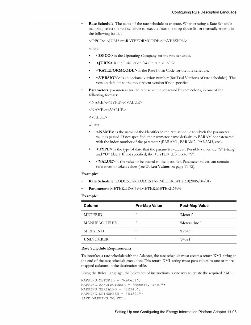
Configuring Rule Description Language
• Rate Schedule: The name of the rate schedule to execute. When creating a Rate Schedule mapping, select the rate schedule to execute from the drop-down list or manually enter it in the following format:
<OPCO>:<JURIS>:<RATEFORMCODE>[:<VERSION>]
where:
• <OPCO> is the Operating Company for the rate schedule.
• <JURIS> is the Jurisdiction for the rate schedule.
• <RATEFORMCODE> is the Rate Form Code for the rate schedule.
• <VERSION> is an optional version number (for Trial Versions of rate schedules). The version defaults to the most recent version if not specified.
• Parameters: parameters for the rate schedule separated by semicolons, in one of the following formats:
<NAME>:<TYPE>:<VALUE>
<NAME>:<VALUE>
<VALUE>
where:
• <NAME> is the name of the identifier in the rate schedule to which the parameter value is passed. If not specified, the parameter name defaults to PARAM concatenated with the index number of the parameter (PARAM1, PARAM2, PARAM3, etc.).
• <TYPE> is the type of date that the parameter value is. Possible values are “S” (string) and “D” (date). If not specified, the <TYPE> defaults to “S”.
• <VALUE> is the value to be passed to the identifier. Parameter values can contain references to token values (see Token Values on page 11-72).
Example:
• Rate Schedule: LODESTAR:LODESTAR:METER_ATTR:0(2006/04/01)
• Parameters: METER_ID:S:%%METER.METERID%%
Example:
Rate Schedule Requirements
To interface a rate schedule with the Adapter, the rate schedule must create a return XML string at the end of the rate schedule execution. This return XML string must pass values to one or more mapped columns in the destination table.
Using the Rules Language, the below set of instructions is one way to create the required XML.
MAPPING.METERID = "Meter1";MAPPING.MANUFACTURER = "Meters, Inc.";MAPPING.SERIALNO = "12345";MAPPING.UNINUMBER = "54321";SAVE MAPPING TO XML;
Column Pre-Map Value Post-Map Value
METERID ‘’ ‘Meter1’
MANUFACTURER ‘’ ‘Meters, Inc.’
SERIALNO ‘’ ‘12345’
UNINUMBER ‘’ ‘54321’
Setting Up and Configuring the Energy Information Platform Adapter 11-93

Configuring Rule Description Language
It’s also possible to create the required XML using the XML Rules Language statements and functions. See Appendix B: XML Statements and Functions in the Oracle Utilities Rules Language Reference Guide for more information about using these functions.
The example below is what actually is returned from the Rules Language after processing the instructions above.
<RSID_VALUES><RSID_STEM NAME="MAPPING"><RSID_VALUE NAME="METERID" VALUE="Meter1"/><RSID_VALUE NAME="MANUFACTURER" VALUE="Meters, Inc."/><RSID_VALUE NAME="SERIALNO" VALUE="12345"/><RSID_VALUE NAME="UNINUMBER" VALUE="54321"/>
</RSID_STEM></RSID_VALUES>
Adding and Editing Column MappingsHow to create a column mapping:
1. Click the column you wish map on the right hand side of the RDL Mapping window.
The Column pane appears below the RDL Mapping window.
The Table, Column, and Source for the mapping will be automatically populated.
2. Select the appropriate mapping type from the Mapping Type drop-down list in the Validations box. See Column Mapping Types and Parameters on page 11-86 for more information about mapping types.
3. Enter parameters for the mapping, based on the selected Mapping Type. See Validation Types and Parameters on page 11-75 for details of type-specific parameters.
4. Enter a Debug Message corresponding to the mapping. Debug messages can contain token values (see Token Values on page 11-72 for more information about token values).
5. Click Save to save the RDL configuration.
How to edit a column mapping:
1. Click the column you wish to map on the right hand side of the RDL Mapping window.
The Column pane appears below the RDL Mapping window.
2. Edit the mapping as needed, and click Save (top of screen).
Validate RDLThe next step in configuring an RDL is to validate the RDL. This function performs a validation on all SQL, Stored Procedures, and scripts in mappings and validations and returns any errors or warnings that are found.
11-94 Energy Information Platform User’s Guide

Configuring Rule Description Language
Define Interval Data ValidationsFor Rule Type Codes of either Import Interval or Interval, the next step is to define the type of interval data validations (if any) that will be performed on the incoming interval data. This section includes:
• Viewing Interval Data Validations
• Interval Data Validation Types and Parameters
• Adding, Editing, and Deleted Interval Data Validations
Viewing Interval Data ValidationsInterval Data Validations can be viewed on the Interval Data Validations screen (displayed below the RDL Mapping window after clicking Interval Data Validations). The tree displays all the interval data validations defined for the RDL. The top element in the tree is always “Rules.” In the validations tree, names of individual validations are displayed in Blue text.
Import IntervalFor Import Interval RDLs, the Interval Data Validations screen opens when the user clicks Interval Data Validations at the top of the screen.
Setting Up and Configuring the Energy Information Platform Adapter 11-95

Configuring Rule Description Language
IntervalFor Interval RDLs, the Interval Data Validations screen automatically displays. RDLs of this type do not use the RDL Mapping window.
Interval Data Validations are defined by the following:
• Settings: the type of validation. Interval Data Validation types include:
• Validate INTD
• Validate SPI
• Validate UOM
• Time Zone Conversions
• Behaviors
See Validation Types and Parameters on page 11-75 for more information about validation types.
• Parameters: Parameters for the validation, based on the validation Settings. See Interval Data Validation Types and Parameters, below for details about type-specific parameters.
Interval Data Validation Types and ParametersEach type of interval data validation has its own set of parameters that define the validation. This section outlines the parameters specific to each type of validation.
Validate INTDValidate INTD validations ensure that the incoming interval data has the correct number of intervals based on the supplied Start and Stop time.
Validate INTD validations use the following parameters:
• Start/Stop Hour: a flag that indicates how the Adapter should handle exceptions related to the Start Time. or Stop Time of the incoming interval data (Ignore or Reject).
• Missing Intervals: a flag that indicates how the Adapter should handle exceptions related to missing intervals in the incoming interval data (Ignore or Reject).
Validate SPIValidate SPI validations ensure that the Seconds-Per-Interval (SPI) of the incoming interval data matches a defined value.
Validate SPI validations use the following parameters:
• Seconds: the specified SPI for incoming interval data. Possible values include:
• 60 (one minute)
11-96 Energy Information Platform User’s Guide

Configuring Rule Description Language
• 300 (5 minutes)
• 900 (15 minutes)
• 1800 (30 minutes)
• 3600 (one hour)
• 86400 (one day)
Validate UOMValidate UOM validations ensure that the Unit-of-Measure (UOM) of the incoming interval data matches a defined value.
Validate UOM validations use the following parameters:
• UOM Code: the specified UOM code for incoming interval data.
• UOM Unit: the specified UOM unit for incoming interval data.
Time Zone ConversionsTime Zone Conversion validations change the time zone of the incoming interval data to a specified time zone.
Time Zone Conversion validations use the following parameters:
• Target Timezone: the target time zone for the incoming interval data. After processing, the time zone for the interval data will be set to this.
• Source Timezone: the original time zone of the incoming interval data.
BehaviorsBehaviors validations allow you specify certain interval data behaviors, similar to those defined in the INTDCONFIG.CFG.XML configuration file.
Behaviors validations use the following parameters:
• OverCount: Controls the behavior of import functions when an incoming cut has too many recorded intervals for the time span defined by the cut start time and the cut stop time and the DST_Participant flag. Valid values include:
• Reject: Directs the function to produce an error and disallow the import of any incoming/uploaded when cut has too many recorded intervals (Expected < Recorded).
• BE: Behaves exactly like Reject, except in the case where a cut that crosses the beginning of a DST period, and has its recorded interval count equal to the expected intervals count without the hour adjusted for DST.
• As Is: Allow the storage of any incoming cuts with a number of expected intervals less than the number of recorded intervals. The stop times of these cuts will remain unchanged.
• UnderCount: Controls the behavior of import functions when an incoming cut has too few recorded intervals for the time span defined by the cut start time and the cut stop time and the DST Participant flag. Valid values include:
• Reject: Directs the function to produce an error and disallow the import of any incoming/uploaded cut when it has too few recorded intervals (Expected > Recorded).
• BE: Directs the function to behave similar to the default behavior observed in previous installations and versions. This setting works exactly like Fill in most cases. When a cut being processed spans the end of the DST period, usually the fall DST hour, if viewed directly from the raw flat file, the cut will appear to be filled using DST calculations, yet if the cut is saved to a binary data source, it will only be filled with missings as if the DST_Participant flag is set to “N”. For example, if a cut is supplied that crosses the Fall DST change and has only 92 intervals (23 hours), the system will fill to only 96 not 100.
Setting Up and Configuring the Energy Information Platform Adapter 11-97

Configuring Rule Description Language
If 100 intervals are supplied, then 100 will be stored. Also, if 97 - 99 intervals are supplied and the DST = “Y”, then the system will Reject the incoming cut.
• Fill: Fills all incoming cuts with missings (value = 0, Status = “9”) to the stop time of the cut using DST adjustments if appropriate (DST_Participant = “Y”).
• As Is: Allows the storage of any incoming cuts with a number of expected intervals greater than the number of recorded intervals. The stop times of these cuts will remain unchanged.
• DST_Participant: Controls any Daylight Saving Time conversions that will be applied to the cut as it is imported into the system. Valid values include:
• Yes: Converts all incoming cuts to follow the default DST rules set in LSCalendar.xml or uses the incoming cut's Time Zone Standard Name (TZSN) if available. This setting changes all incoming cuts with DST_Participant flags set to “A” or “N” to “Y” and converts the cuts using the DST conversion algorithm for that TZSN.
• No: Converts all incoming cuts not to follow the DST rules associated with them via the TZSN or by using the default set in LSCalendar.xml. This setting changes all incoming cuts with DST_Participant flags set to “A” or “Y” to “N”.
• As Is: Allows cuts to be entered into the system without using any conversions. The DST_Participant flags remain as they are supplied. This can results in databases that have mixed DST_Participant cuts, and is not recommended if the data source will be used with Oracle Utilities Load Analysis.
• Force Valid: Controls the behavior of how the system sets the Validate_Record_Flag. Valid values include:
• Yes: Sets the Validate_Record_Flag to “Y” indicating that the record should be validated after importing.
• No: Sets the Validate_Record_Flag to “N” indicating that the cut needs no further validation when imported.
• Flag: Uses the cuts' Internal_Validation and Merge flag to set the Validate_Record_Flag. If either are set to “Y”, then the Validate_Record_Flag is set to “N”, otherwise it is set to “Y”.
• Set DST A Records: Sets rules on how to import cuts with the Participant flag set to “A”. Valid values include:
• Yes: Convert the cut from a properly formatted “A” record to one that follows DST rules, provided the TZSN is also supplied. If the TZSN is not supplied, the function uses the default TZSN. The cut will be transformed into the original DST = “Y”. When using Time Zone Conversions in Data Manager or the INTDIMP.EXE command line program, the program will only import cuts in the LSE, XML, CSV file formats that originally have the requested DST_Participant flag. All others produce an error. For Example, if an incoming file has a mixture of DST_Participant cuts, and the Input/Meter Time Zone is EDTA, then only cuts in the file with DST_Participant flags of A will be imported. The cuts will be converted to DST = “Y” in this case.
• No: Results in the same processing as the “Y” setting, followed by a conversion of start and/or stop times by one hour to create a non-DST cut.
• Reject: Results in the cut being rejected and produces an error.
• As Is: Imports as Data Manager has always done it.
• Set Missing DST Participant: Controls the default value assigned to the DST_Participant Flag when the incoming cut does not contain the flag. Valid values include:
• Y: Sets the DST_Participant flag to “Y”.
• N: Sets the DST_Participant flag to “N”.
11-98 Energy Information Platform User’s Guide

Configuring Rule Description Language
• Set Invalid DST Participant: Controls the behavior of the import and loading of cuts when the DST_Participant flag in the source cut is not an A, N, or Y. Valid values include:
• Y: Sets the DST_Participant flag of an incoming cut with an invalid DST_Participant flag to Y.
• N: Sets the DST_Participant flag of an incoming cut with an invalid DST_Participant flag to N.
• Reject: Does not allow the cut to be imported.
Adding, Editing, and Deleted Interval Data ValidationsHow to create an interval data validation:
1. Click Interval Data Validations.
The Interval Data Validations window appears below the RDL Mapping window. This window is automatically displayed when configuring RDLs of Rule Type Interval.
2. Select the appropriate interval data validation type from the Type drop-down list in the interval data validations box. See Interval Data Validation Types and Parameters on page 11-96 for more information about interval data validation types.
3. Enter parameters for the validation, based on the validation Type. See Interval Data Validation Types and Parameters on page 11-96 for details of type-specific parameters.
4. Click Add in the interval data validations box to add the validation.
The validation appears in the Interval Data Validations tree, under the Rules element.
How to edit an interval data validation:
1. Click Interval Data Validations.
The Interval Data Validations window appears below the RDL Mapping window. This window is automatically displayed when configuring RDLs of Rule Type Interval.
2. Click the Validation Name of the validation you wish to edit.
3. Edit the validation as needed, and click Update in the interval data validations box.
How to delete an interval data validation:
1. Click Interval Data Validations.
The Interval Data Validations window appears below the RDL Mapping window. This window is automatically displayed when configuring RDLs of Rule Type Interval.
2. Click the Validation Name of the validation you wish to delete.
3. Click Delete in the interval data validations box.
The selected validation no longer appears in the Interval Data Validations tree.
Setting Up and Configuring the Energy Information Platform Adapter 11-99

RDL Configuration Examples
RDL Configuration ExamplesThis section includes examples of common tasks and how they can be performed with RDL mappings and validations, and includes:
• Mapping Examples
• Validation Examples
Mapping ExamplesMapping examples illustrate how to configure column mappings to insert specific values into the Oracle Utilities Data Repository based on data from the incoming payload and other sources. See Define Column Mappings on page 11-84 for more information.
Looking Up Values There can be situations when a table requires a value that is not in the payload but exists in another table in the Oracle Utilities Data Repository. A SQL statement can perform a lookup for one or more values to be inserted into the database.
The following SQL statement retrieves the MARKETID and SERVICETYPE from the LSMARKET table to complete the database update.
Sample SQL Statementselect MARKETID, SERVICETYPE from %%QUAL%%.LSMARKET where uidmarket = (select uidmarket from %%QUAL%%.LSSERVICEPOINT where servicepointid ='%%GLOBAL.SP_ID%%')
11-100 Energy Information Platform User’s Guide

RDL Configuration Examples
Converting and Enriching Date ValuesDate values in the Oracle Utilities Data Repository use a standard format. In the cases where date formats in the payload are not in an acceptable format, you can convert and/or enrich the date value.
The following JAVA Script evaluation is used to enrich a date and convert it to a new format. The time "23:59:59" is added to the date string.
Stop Time Java Script Enrichment'%%THIS%%'.substring(5,7)+'/'+'%%THIS%%'.substring(8,10)+'/'+'%%THIS%%'.substring(0,4)+' 23:59:59'
The following VB Script evaluation is used to parse a date and convert it to a new format (yyyy-m-d 00:00:00).
Setting Up and Configuring the Energy Information Platform Adapter 11-101

RDL Configuration Examples
VB Script Function CallDatePart("yyyy","%%THIS%%") & "-" & DatePart("m","%%THIS%%") & "-" & DatePart("d","%%THIS%%") & " 00:00:00"
Converting ValuesSometimes data values in an incoming payload may not match those used by Oracle Utilities applications. For instance, Oracle Utilities applications use specific codes for different units of measure. In such cases, a mapping can convert incoming values to Oracle Utilities-compatible values.
The following JAVA Script converts the unit of measure in the payload to standard Unit-of-Measure codes. Note that there are more codes than shown in this example.
JavaScript CodeUOM('%%THIS%%')
function UOM(sUOM) { var retval; switch (sUOM) {case 'K1': retval='02'; break;
case 'K2': retval='22'; break;
case 'K3': retval='04'; break;
case 'KH': retval='01'; break;}
return retval;}
11-102 Energy Information Platform User’s Guide

RDL Configuration Examples
Selecting a Single Value from a Delimited FieldValues in incoming payloads can be delimited fields from which you might need to extract a single value.
The following JAVA Script Evaluation parses a delimited string to pull out a particular value. The following code takes the mapped value "%%THIS%%" and pulls out the fourth item (base zero). Note that the "," denotes the delimiter used.
Java Script Evaluation Code #1("%%THIS%%").split(",")[3]
Input
XXX, YYY, ZZZ, AAA
Output
AAA
Using the System DateYou can use the database system date as a mapped value.
The following SQL statement uses the Oracle system date as a mapped value. Note that the system will require you to map a "dummy" source element. The SQL will override the mapping value.
Sample SQL StatementSELECT SYSDATE as TXNPROCESSDATE FROM DUAL
Setting Up and Configuring the Energy Information Platform Adapter 11-103

RDL Configuration Examples
Calling an Oracle SequenceSQL mappings can call Oracle sequences.
The following SQL statement calls an Oracle sequence to generate a unique reference when required. Note that the sequence to be called must have been previously built in Oracle.
Sample SQL StatementSELECT DEMO_LSSRVCPTINVDETAIL.NEXTVAL AS INVOICEDETAILID FROM DUAL
11-104 Energy Information Platform User’s Guide

RDL Configuration Examples
Validation ExamplesValidation examples illustrate how to configure table validations when inserting records into the Oracle Utilities Data Repository. See Define Table Validations on page 11-74 for more information.
Validating a Customer ID using SQLSQL validations can check that a look up or parent record exists prior to inserting a record into the Oracle Utilities Data Repository. For example, you might want to check that the Customer ID associated with an Account to be inserted exists.
The following SQL statement checks the Customer ID in the Customer table prior to inserting the account record.
Sample SQL StatementSELECT CUSTOMERID FROM CUSTOMER WHERE CUSTOMERID='%%ACCOUNT.CUSTOMERID%%'
Setting Up and Configuring the Energy Information Platform Adapter 11-105

RDL Configuration Examples
Calling a Stored ProcedureTable validations can use stored procedures.
The following stored procedure checks to ensure the METER ID is correct. Note that the SQL returns TRUE or FALSE to the adapter.
Sample Stored ProcedureCREATE OR REPLACE function FN_METER_CHECK(sMETERID varchar2) return varchar2 is
ErrorDate varchar2(64);iCount number;statusmsg varchar2(64);
begin dbms_output.enable;
dbms_output.put_line('in stored procedure');
statusMsg := 'TRUE'; iCount := 0;
select count(METERID) into iCount from METER where METERID = sMETERID;
if iCount = 0 then statusmsg:= 'FALSE'; end if;
dbms_output.put_line(StatusMsg);RETURN STATUSMSG;
end FN_METER_CHECK;/
11-106 Energy Information Platform User’s Guide

Defining Properties and Parameters for Adapter Business Rules
Defining Properties and Parameters for Adapter Business RulesThis section describes the Properties and Parameters used by Adapter Business Rules, including:
• Properties Format
• Import Properties and Parameters
• Import/Interval Properties and Parameters
• Interval Properties and Parameters
• Assembly Properties and Parameters
• COM Properties and Parameters
• CustomQuery Properties and Parameters
• Rate Properties and Parameters
Properties FormatAdapter Business Rules are defined in the Business Rules table in the Oracle Utilities Data Repository. The Properties column in this table defines specific properties expected and/or required by the business rule. This column should contain an XML string listing the properties used by the service.
The Properties XML string should be in the following form:
<PROPERTIES><PROPERTY NAME="PropertyName1" VALUE="PropertyValue1"/><PROPERTY NAME="PropertyName2" VALUE="PropertyValue2"/>...
</PROPERTIES>
Element DescriptionsEach of the data elements used by this structure are described below.
Elements:
• PROPERTIES: Root element that contains one or more PROPERTY elements.
• PROPERTY: Element that defines a specific Property used by the service.
Attributes:
• NAME: The name of the Property.
• VALUE: The value for the Property.
Names and appropriate values for each property are listed in the descriptions below.
Property DescriptionsEach of the properties used by the services are described in the following format:
PROPERTY: NAME: The name of the Property.
• Required: Is the Property required?
• Possible Values: Possible values for the Property.
• Description: A description of the Property.
• Example: An example of the Property.
Setting Up and Configuring the Energy Information Platform Adapter 11-107

Defining Properties and Parameters for Adapter Business Rules
Import Properties and ParametersImport business rules use the following properties. Import business rules do not use parameters. See Chapter 6: Setting Up, Configuring, and Running the Energy Information Platform Adapter in the Oracle Utilities Energy Information Platform Configuration Guide for more information about implementing Import business rules.
PROPERTY: xmlstream• Required: Yes
• Possible Values: “y” or “n”
• Description: Instructs the Adapter parsing engine to keep the XML data that is to be sent to the database engine. Valid values are:
• y - Yes, keep the XML data sent to the database engine.
• n - No, do not keep the XML data sent to the database engine.
• Example:
<PROPERTY NAME='xmlstream' VALUE='y'/>
PROPERTY: mode• Required: Yes
• Possible Values: “event” or “batch”
• Description: Instructs the Adapter parsing engine to perform database operations on a per table basis (“event”) or as a batch done at the end of the incoming payload document (“batch”).
• Example:
<PROPERTY NAME='mode' VALUE='event'/>
PROPERTY: XslConverter• Required: No
• Possible Values: string containing valid network path
• Description: Optional property specifying the full class name of an XML converter to apply to the payload. See XML Converters on page 6-32 in the Oracle Utilities Energy Information Platform Configuration Guide for more information about XML Converters.
• Example:
<PROPERTY NAME='XslConverter' VALUE='c:\lodestar\bin\billing.xslt'/>
Example of Import properties:<PROPERTIES><PROPERTY NAME='xmlstream' VALUE='y'/><PROPERTY NAME='mode' VALUE='event'/>
</PROPERTIES>
11-108 Energy Information Platform User’s Guide

Defining Properties and Parameters for Adapter Business Rules
Import/Interval Properties and ParametersImport/Interval business rules use the same properties as Import business rules, but can also use other properties for processing interval data. Import/Interval business rules do not use parameters. See Chapter 6: Setting Up, Configuring, and Running the Energy Information Platform Adapter in the Oracle Utilities Energy Information Platform Configuration Guide for more information about implementing Import/Interval business rules.
PROPERTY: intdheadertable• Required: No
• Possible Values: Table name for interval data header information.
• Description: Specifies that interval data header information should be inserted into the table specified by this property instead of into the Channel Cut Header (LSCHANNELCUTHEADER) table.
• Example:
<PROPERTY NAME='intdheadertable' VALUE='LSCHCLDB'/>
PROPERTY: intddatatable• Required: No
• Possible Values: Table name for interval data information.
• Description: Specifies that interval data information should be inserted into the table specified by this property instead of into the Channel Cut Data (LSCHANNELCUTDATA) table.
• Example:
<PROPERTY NAME='intddatatable' VALUE='LSCHCLDBDATA'/>
PROPERTY: XslConverter• Required: No
• Possible Values: string containing valid network path
• Description: Optional property specifying the full class name of an XML converter to apply to the payload. See XML Converters on page 6-32 in the Oracle Utilities Energy Information Platform Configuration Guide for more information about XML Converters.
• Example:
<PROPERTY NAME='XslConverter' VALUE='c:\lodestar\bin\billing.xslt'/>
Example of Import Interval properties:<PROPERTIES><PROPERTY NAME='xmlstream' VALUE='y'/><PROPERTY NAME='mode' VALUE='event'/><PROPERTY NAME='intdheadertable' VALUE='LSCHCLDB'/><PROPERTY NAME='intddatatable' VALUE='LSCHCLDBDATA'/>
</PROPERTIES>
Setting Up and Configuring the Energy Information Platform Adapter 11-109
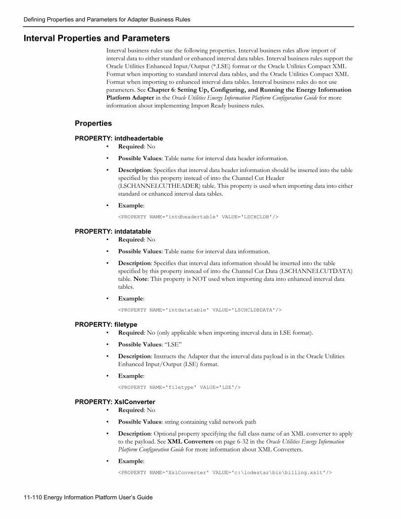
Defining Properties and Parameters for Adapter Business Rules
Interval Properties and ParametersInterval business rules use the following properties. Interval business rules allow import of interval data to either standard or enhanced interval data tables. Interval business rules support the Oracle Utilities Enhanced Input/Output (*.LSE) format or the Oracle Utilities Compact XML Format when importing to standard interval data tables, and the Oracle Utilities Compact XML Format when importing to enhanced interval data tables. Interval business rules do not use parameters. See Chapter 6: Setting Up, Configuring, and Running the Energy Information Platform Adapter in the Oracle Utilities Energy Information Platform Configuration Guide for more information about implementing Import Ready business rules.
Properties
PROPERTY: intdheadertable• Required: No
• Possible Values: Table name for interval data header information.
• Description: Specifies that interval data header information should be inserted into the table specified by this property instead of into the Channel Cut Header (LSCHANNELCUTHEADER) table. This property is used when importing data into either standard or enhanced interval data tables.
• Example:
<PROPERTY NAME='intdheadertable' VALUE='LSCHCLDB'/>
PROPERTY: intdatatable• Required: No
• Possible Values: Table name for interval data information.
• Description: Specifies that interval data information should be inserted into the table specified by this property instead of into the Channel Cut Data (LSCHANNELCUTDATA) table. Note: This property is NOT used when importing data into enhanced interval data tables.
• Example:
<PROPERTY NAME='intdatatable' VALUE='LSCHCLDBDATA'/>
PROPERTY: filetype• Required: No (only applicable when importing interval data in LSE format).
• Possible Values: “LSE”
• Description: Instructs the Adapter that the interval data payload is in the Oracle Utilities Enhanced Input/Output (LSE) format.
• Example:
<PROPERTY NAME='filetype' VALUE='LSE'/>
PROPERTY: XslConverter• Required: No
• Possible Values: string containing valid network path
• Description: Optional property specifying the full class name of an XML converter to apply to the payload. See XML Converters on page 6-32 in the Oracle Utilities Energy Information Platform Configuration Guide for more information about XML Converters.
• Example:
<PROPERTY NAME='XslConverter' VALUE='c:\lodestar\bin\billing.xslt'/>
11-110 Energy Information Platform User’s Guide

Defining Properties and Parameters for Adapter Business Rules
Examples of Interval properties:Importing LSE data into a standard interval data table:
<PROPERTIES><PROPERTY NAME='intdheadertable' VALUE='LSCHCLDB'/><PROPERTY NAME='intdatatable' VALUE='LSCHCLDBDATA'/><PROPERTY NAME='filetype' VALUE='LSE'/>
</PROPERTIES>
Importing XML data into an enhanced interval data table:
<PROPERTIES><PROPERTY NAME='intdheadertable' VALUE='LSWEATHERDATA'/>
</PROPERTIES>
Assembly Properties and ParametersAssembly business rules use the following properties and parameters. See Chapter 6: Setting Up, Configuring, and Running the Energy Information Platform Adapter in the Oracle Utilities Energy Information Platform Configuration Guide for more information about implementing Assembly business rules.
Properties
PROPERTY: assembly• Required: Yes
• Description: .NET assembly
• Example:
<PROPERTY NAME='assembly' VALUE='Lodestar.MDM'/>
PROPERTY: class• Required: Yes
• Description: .NET class name
• Example:
<PROPERTY NAME='class' VALUE='Lodestar.MDM.BusinessRules.MeterPingTWACS'/>
PROPERTY: method• Required: Yes
• Description: Method name to execute.
• Example:
<PROPERTY NAME='method' VALUE='Execute'/>
PROPERTY: WQQUEUE• Required: Yes
• Description: Work Queue queue code for function calls and errors
• Example:
<PROPERTY NAME='WQQUEUE' VALUE='TWACS'/>
PROPERTY: WQTYPE• Required: Yes
• Description: Work Queue type used to identify function calls
• Example:
Setting Up and Configuring the Energy Information Platform Adapter 11-111

Defining Properties and Parameters for Adapter Business Rules
<PROPERTY NAME='WQTYPE' VALUE='METERPING'/>
PROPERTY: WQEXCEPTIONTYPE• Required: Yes
• Description: Work Queue type used to identify failures
• Example:
<PROPERTY NAME='WQEXCEPTIONTYPE' VALUE='METERPINGEXCEPTION'/>
PROPERTY: XslConverter• Required: No
• Possible Values: string containing valid network path
• Description: Optional property specifying the full class name of an XML converter to apply to the payload. See XML Converters on page 6-32 in the Oracle Utilities Energy Information Platform Configuration Guide for more information about XML Converters.
• Example:
<PROPERTY NAME='XslConverter' VALUE='c:\lodestar\bin\billing.xslt'/>
Example of Assembly properties:<PROPERTIES><PROPERTY NAME='assembly' VALUE='Lodestar.MDM'/><PROPERTY NAME='class' VALUE='Lodestar.MDM.BusinessRules.MeterPingTWACS'/><PROPERTY NAME='method' VALUE='Execute'/><PROPERTY NAME='WQQUEUE' VALUE='TWACS'/><PROPERTY NAME='WQTYPE' VALUE='METERPING'/><PROPERTY NAME='WQEXCEPTIONTYPE' VALUE='METERPINGEXCEPTION'/>
</PROPERTIES>
ParametersParameters for Assembly business rules are based on the parameters used by the assembly method to be called.
COM Properties and ParametersCOM business rules use the following properties and parameters. See Chapter 6: Setting Up, Configuring, and Running the Energy Information Platform Adapter in the Oracle Utilities Energy Information Platform Configuration Guide for more information about implementing COM business rules.
Properties
PROPERTY: progid• Required: No
• Possible Values: A valid progid for the COM method to be called.
• Description: The progid used by the Adapter to locate the COM component itself. The Adapter cannot run the COM method if it cannot find the COM component. If either the progid or the method name cannot be found, then an error is reported.
• Example:
<PROPERTY NAME='progid' VALUE='LSACCT.Remittance'/>
PROPERTY: method• Required: No
• Possible Values: A valid COM method
11-112 Energy Information Platform User’s Guide

Defining Properties and Parameters for Adapter Business Rules
• Description: A valid COM method with the appropriate number of parameters and the correctly formatted return XML.
• Example:
<PROPERTY NAME='method' VALUE='PostPayment'/>
PROPERTY: xmlstream• Required: No
• Possible Values: “y” or “n”
• Description: Used to return the completion status of the COM method call. If the user would like to be able to pass data back to a file or a message queue, then the outbound data and the xmlstream property are important.
• Example:
<PROPERTY NAME='xmlstream' VALUE='y'/>
PROPERTY: XslConverter• Required: No
• Possible Values: string containing valid network path
• Description: Optional property specifying the full class name of an XML converter to apply to the payload. See XML Converters on page 6-32 in the Oracle Utilities Energy Information Platform Configuration Guide for more information about XML Converters.
• Example:
<PROPERTY NAME='XslConverter' VALUE='c:\lodestar\bin\billing.xslt'/>
Example of COM properties:<PROPERTIES><PROPERTY NAME='progid' VALUE='LSACCT.Remittance'/><PROPERTY NAME='method' VALUE='PostPayment'/><PROPERTY NAME='xmlstream' VALUE='y'/>
</PROPERTIES>
ParametersParameters for COM business rules include the parameters used by the COM method to be called.
CustomQuery Properties and ParametersCustomQuery business rules use the following properties and parameters. See Chapter 6: Setting Up, Configuring, and Running the Energy Information Platform Adapter in the Oracle Utilities Energy Information Platform Configuration Guide for more information about implementing CustomQuery business rules.
Properties
PROPERTY: STORED_PROCEDURE_NAME• Required: Yes
• Description: The name of the custom query to call
• Example:
<PROPERTY NAME='STORED_PROCEDURE_NAME' VALUE='sp-get-meters'/>
PROPERTY: XslConverter• Required: No
• Possible Values: string containing valid network path
Setting Up and Configuring the Energy Information Platform Adapter 11-113
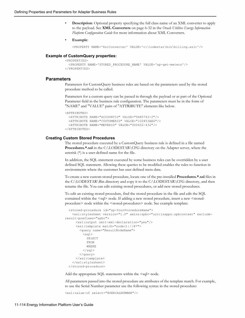
Defining Properties and Parameters for Adapter Business Rules
• Description: Optional property specifying the full class name of an XML converter to apply to the payload. See XML Converters on page 6-32 in the Oracle Utilities Energy Information Platform Configuration Guide for more information about XML Converters.
• Example:
<PROPERTY NAME='XslConverter' VALUE='c:\lodestar\bin\billing.xslt'/>
Example of CustomQuery properties:<PROPERTIES><PROPERTY NAME='STORED_PROCEDURE_NAME' VALUE='sp-get-meters'/>
</PROPERTIES>
ParametersParameters for CustomQuery business rules are based on the parameters used by the stored procedure method to be called.
Parameters for a custom query can be passed in through the payload or as part of the Optional Parameter field in the business rule configuration. The parameters must be in the form of "NAME" and "VALUE" pairs of "ATTRIBUTE" elements like below.
<ATTRIBUTES><ATTRIBUTE NAME="ACCOUNTID" VALUE="9485763-2"/><ATTRIBUTE NAME="CUSTOMERID" VALUE="102853AEG"/><ATTRIBUTE NAME="METERID" VALUE="000452-432"/>
</ATTRIBUTES>
Creating Custom Stored ProceduresThe stored procedure executed by a CustomQuery business rule is defined in a file named Procedures.*.xsl in the C:\LODESTAR\CFG directory on the Adapter server, where the asterisk (*) is a user-defined name for the file.
In addition, the SQL statement executed by some business rules can be overridden by a user defined SQL statement. Allowing these queries to be modified enables the rules to function in environments where the customer has user defined meta-data.
To create a new custom stored procedure, locate one of the pre-installed Procedures.*.xsl files in the C:\LODESTAR\Bin directory and copy it to the C:\LODESTAR\CFG directory, and then rename the file. You can edit existing stored procedures, or add new stored procedures.
To edit an existing stored procedure, find the stored procedure in the file and edit the SQL contained within the <sql> node. If adding a new stored procedure, insert a new <stored-procedure> node within the <stored-procedures> node. See example template:
<stored-procedure id="sp-YourProcedureName"><xsl:stylesheet version="1.0" xmlns:spbc="urn:lsapps.spbcontext" exclude-
result-prefixes="spbc"><xsl:output omit-xml-declaration="yes"/><xsl:template match="node()|/|@*"><query name="ResultNodeName"><sql>SELECTFROM WHERE
</sql></query>
</xsl:template></xsl:stylesheet>
</stored-procedure>
Add the appropriate SQL statements within the <sql> node.
All parameters passed into the stored procedure are attributes of the template match. For example, to use the Serial Number parameter use the following syntax in the stored procedure:
<xsl:value-of select="@SERIALNUMBER"/>
11-114 Energy Information Platform User’s Guide

Defining Properties and Parameters for Adapter Business Rules
Rate Properties and ParametersRate (Oracle Utilities Rules Language) business rules use the following properties and parameters. See Chapter 6: Setting Up, Configuring, and Running the Energy Information Platform Adapter in the Oracle Utilities Energy Information Platform Configuration Guide for more information about implementing Rate business rules.
Properties
PROPERTY: turnoffratecaching• Required: No
• Possible Values: “y” or “true”
• Description: Used to turn off rate schedule caching for rate schedules executed by the Adapter. This property should not be used with the Adapter web service interface.
• y - Yes, turn off rate schedule caching for rate schedules executed by the Adapter.
• true - Yes, turn off rate schedule caching for rate schedules executed by the Adapter.
• Example:
<PROPERTY NAME='turnoffratecaching' VALUE='y'/>
PROPERTY: useclserver• Required: No
• Possible Values: “y” or “true”
• Description: Used to direct Adapter rate business rules to execute using the Rules Language COM server as a separate process. This is an out of process COM server than will run the request and then exit.
• y - Yes, execute using the Rules Language COM server as a separate process.
• true - Yes, execute using the Rules Language COM server as a separate process.
• Example:
<PROPERTY NAME='useclserver' VALUE='y'/>
PROPERTY: xmlstream• Required: No
• Possible Values: “y” or “n”
• Description: Used to return an outbound payload to the client process. It is not mandatory to return a outbound payload.
• y - Yes, return an outbound payload to the client process.
• n - No, do not return an outbound payload to the client process.
• Example:
<PROPERTY NAME='xmlstream' VALUE='y'/>
PROPERTY: XslConverter• Required: No
• Possible Values: string containing valid network path
• Description:Optional property specifying the full class name of an XML converter to apply to the payload. See XML Converters on page 6-32 in the Oracle Utilities Energy Information Platform Configuration Guide for more information about XML Converters.
• Example:
Setting Up and Configuring the Energy Information Platform Adapter 11-115

Defining Properties and Parameters for Adapter Business Rules
<PROPERTY NAME='XslConverter' VALUE='c:\lodestar\bin\billing.xslt'/>
Example of Rate properties:<PROPERTIES><PROPERTY NAME='xmlstream' VALUE='y'/>
</PROPERTIES>
ParametersParameters for Rate business rules include an XML structure that indicates the rate schedule to be run.
Example:<LODESTAR_RUNSCHEDULE><DATASOURCE><NAME>Local</NAME><CONNECTSTRING>DSN=local;UID=User1;PWD=password;</CONNECTSTRING><QUALIFIER>testq</QUALIFIER>
</DATASOURCE><TIMEOUT>3600</TIMEOUT><CONFIG_FILE_NAME>c:\lodestar\cfg\lodestar.cfg</CONFIG_FILE_NAME><SCHEDULE_ARGUMENTS><INTERVAL_DATABASE>RDB</INTERVAL_DATABASE><RATE_FORM_IDENTIFIER>GLOBAL:GLOBAL:TEST_SCHEDULE</RATE_FORM_IDENTIFIER><START_DATE>2003/11/25</START_DATE><SAVE_RESULTS/><INTERVAL_DATA_ERROR>3</INTERVAL_DATA_ERROR><ACCOUNT><ALL/></ACCOUNT><RSID_VALUES><RSID_VALUE NAME="TEST" TYPE="S" VALUE="TEST VALUE" />
</RSID_VALUES></SCHEDULE_ARGUMENTS>
</LODESTAR_RUNSCHEDULE>
Element Definitions:Each of the data elements used in this structure is described below.
LODESTAR_RUNSCHEDULE: Root element containing a DATASOURCE and SCHEDULE_ARGUMENTS element that define the rate schedule to be run.
Elements:
DATASOURCE: Element containing connection information for the data source to be accessed by the rate schedule.
Elements:
NAME: Name of the data source.
CONNECTSTRING: Connection string to the data source, using the following syntax: DSN=local; UID=User1; PWD=password;
QUALIFIER: Qualifier for the data source.
TIMEOUT: Number of seconds after which the process will time out.
USERID: User name of the user initiating the rate schedule.
CONFIG_FILE_NAME: The name of the configuration file that defines the working environment of the software (e.g., directs the software where to find and place the application data files and so on). If you do not supply a value for configfilename, the system uses the default, which is LODESTAR.CFG. For information about the contents of this configuration file, please refer to the Oracle Utilities Energy Information Platform Configuration Guide.
SCHEDULE_ARGUMENTS: Element containing specific arguments and parameters used by the rate schedule.
11-116 Energy Information Platform User’s Guide

Defining Properties and Parameters for Adapter Business Rules
Elements:
INTERVAL_DATABASE_NAME: The name of the Interval Database (btrieve file) that contains the interval data for the calculations. RDB indicates the rate schedule use the interval data stored in the LSChannel Cut Header table in the Oracle Utilities Data Repository.
RATE_FORM_IDENTIFIER: The identifier for the rate form. Required. OPCO:JUR:RS[:VER] are the operating company code, jurisdiction code, rate form code, and optional version number that together identify the rate form. If you do not supply a version number, the program automatically uses the rate form that was applicable on the stop date of the analysis period (see STOP_DATE). If you do supply a version number, the program uses the trial version indicated (typically used only for testing).
START_DATE: The start date of the date range for the calculations. You can specify the date as an absolute or relative value, as described in Chapter 8: Setting Up Processing to run in Batch Mode in the Oracle Utilities Energy Information Platform Configuration Guide.
STOP_DATE: The stop date of the date range for the calculations. You can specify the date as an absolute or relative value, as described in Chapter 8: Setting Up Processing to run in Batch Mode in the Oracle Utilities Energy Information Platform Configuration Guide.
SAVE_RESULTS: Tells the program to save the results, as specified in the rate form. If you leave this switch out of the command, the program ignores all SAVE statements in the rate form (this is useful if you want to debug the rate form before using it in a production mode, for example). If you supply the switch, the program saves interval data, table saves, and CIS records. Since RUNRS does not input an account, there is no saving of determinants to a Bill History record, unless -ai is specified (see below).
INTERVAL_DATA_ERROR: Sets interval data handling. Uses the same values as the INTD_ERROR_STOP configuration parameter (0,1,2,3). Default # is 1 (error stop).
ACCOUNT: Optional Account All/ID/List name - default is no account. If you specify ID you can save to the Bill History Table.
CUSTOMER: Optional Customer All/ID/List name - default is no customer.
Elements: (apply to either ACCOUNT or CUSTOMER)
ALL: Specifies whether or not to process all Accounts/Customers. See ACCOUNT/CUSTOMER above.
ID: Specifies the Account/Customer ID to process. See ACCOUNT/CUSTOMER above.
LIST_NAME: Specifies the list name of Accounts/Customers to process. See ACCOUNT/CUSTOMER above.
RSID_VALUES: Element that contains rate schedule identifiers values.
Elements:
RSID_VALUE: Element containing a single rate schedule identifier value.
Attributes:
NAME: The name of the identifier value.
TYPE: The type of the identifier value. Can be “S” (string), “D” (date), or “F” (float).
VALUE: The value for the identifier.
Setting Up and Configuring the Energy Information Platform Adapter 11-117

Searching Adapter Transactions
Searching Adapter TransactionsThe Search Adapter Runtime option allows users to search for inbound transactions handled by the Adapter.
How to search inbound Adapter transactions:
1. Select Tools and Utilities-›Adapter Runtime-›Search.
The Inbound screen opens.
2. Enter the search criteria in the appropriate field.
You can search based on the ID, Inbound Source, Inbound Filename, Payload Type (ADAPTER), Receive Date, and Status code of the transaction(s).
See Searching Database Tables on page 8-7 for more information about searching records, including the use of operands and wildcards.
To include child records, check the Include Child Records checkbox.
3. Click Search to perform the search. To reset the search fields to their previous values, click Reset. To clear all the search fields, click Clear.
4. The search results appear on the Inbound screen.
The Inbound screen displays the following information for each transaction:
• ID
• Inbound Source
• Inbound Filename
• Receive Date
• Status Code
See Viewing Adapter Transactions on page 11-119 for more information about viewing individual transactions.
5. To sort the results by one of the columns, click the appropriate column heading. For example, to sort the results by Inbound Source, click the Inbound Source column heading. If there is
more than one page of results, you can move between pages using the and buttons. To change the number of results that appears on each page, enter the number in the Rows field.
6. To view a transaction, click on the corresponding [...] link. The selected transaction will appear in the Inbound window. See Viewing Adapter Transactions on page 11-119 for more information.
7. To perform another search, click Search. To refresh the contents of the Inbound screen, click the refresh icon.
11-118 Energy Information Platform User’s Guide

Viewing Adapter Transactions
Viewing Adapter TransactionsIndividual inbound transactions are viewed on the Inbound screen. This screen opens when you select a transaction from the Inbound search results screen.
The Inbound screen displays the following information for the transaction displayed:
• ID: The ID of the inbound transaction. IDs are generated by the Adapter when processed.
• Inbound Source: The source of the inbound transaction. This is the name of the Runtime Service that processes the payload.
• Inbound Filename: The filename, payload type, or JMS queue name of the inbound transaction.
• Receive Date: The date the inbound transaction was received.
• Status Code: The status code of the inbound transaction. The status code can be one of the following:
• C: Completed
• E: Error
• Child Records: A list of child records associated with the inbound transaction. Child records are only created if using the Adapter Payload Splitter. See Viewing Child Records on page 11-120 for more information.
• Exceptions: A list of exceptions associated with the inbound transaction. Exceptions are stored in the Inbound Exception table. See Viewing Exceptions on page 11-120 for more information about viewing exceptions on the Inbound screen.
Setting Up and Configuring the Energy Information Platform Adapter 11-119

Viewing Adapter Transactions
Viewing Child RecordsChild records associated with the inbound payload are listed in the Child Records pane. These are portions of the incoming payload that have been created by the Adapter Payload Splitter. If there
is more than one page of child records, you can move between pages using the and buttons. To change the number of results that appears on each page, enter the number in the Rows field.
The Child Record pane displays the following information for each child record:
• ID: The ID of the child record. IDs are generated by the Adapter when processed.
• Inbound Source: The source of the inbound child record. This is the name of the Runtime Service that processes the payload.
• Inbound Filename: The filename, payload type, or queue name of the inbound child record.
• Receive Date: The date the inbound child record was received.
• Status Code: The status code of the inbound child record. The status code can be one of the following:
• C: Completed
• E: Error
To view a child record, click on the corresponding [...] link. The selected record will appear in the Inbound window.
Viewing ExceptionsExceptions associated with the inbound payload are listed in the Exceptions pane. If there is more
than one page of exceptions, you can move between pages using the and buttons. To change the number of results that appears on each page, enter the number in the Rows field.
The Exceptions pane displays the following information for each exception:
• ID: The ID of the exception.
• Exception Source: The source of the exception.
• Exception Date: The date on which the exception occurred.
• Exception Message: The message associated with the exception.
Viewing PayloadsTo view the transaction’s payload, click View Payload. The Payload window opens, displaying the transaction’s payload in XML format.
Note that a transaction’s payload is only viewable if the STORAGE_LEVEL property for the Runtime Service used to process the payload is set to 1 or 2. See Common Properties on page 11-29 for more information.
If a delimited file is not converted to XML, attempts to view the payload will return an error. To view the payload, right-click in the error page and select View Source.
11-120 Energy Information Platform User’s Guide

Index
AAccount
viewing 4-8, 6-19Account dashboard 4-9Account Determinants
Retrieve all 3-16retrieve all 3-16
Account NotesWhen not to use 3-18
Account Override History recordsadding 4-18editing 4-17
Account Rate Code History Table 3-17Account search results screen 4-9Account window 4-8, 6-16
Billing tab 4-16Collections tab 4-25Summary tab 4-19
Account window tabs 4-9Account’s Meter Values
When not to use 3-19Accounts with multiple Bill History records per bill period
processing 3-17Accounts with multiple rates 3-17Add a Customer window 4-3Add Fall Daylight Savings Time Value to Energy requests 3-12Add/Update 6-21, 6-25Adding a customer 4-3Adding a market participant 5-3Adding a service point 5-11Adding Account Override History records 4-18Adding an account to a customer 4-7Adding Bill History Value records 4-17Adding meter history records 4-14Adding meter reads 6-17Adding Report Titles 3-21All Details 3-21All Print Detail option 3-17Allow Multiple Bill History Records per Bill Period/Read Date
3-17Allow saves without SAVE TO CIS Statement 3-16Allowing Multiple Bill History Records per Bill Period/Read
Date 3-17Alpha Codes 3-12Analysis options 3-14Approval Required mode 3-15
Auto Payment Plan Table 4-21Automatic Billing mode 3-15Automatically calculating bills 3-15
BBill calculation
automatic 3-15Bill Determinant Use
When not to use 3-19Bill History Problem record 3-17Bill History Problem records 3-17Bill History records
sub-period 3-18viewing 4-16
Bill History Value recordsadding 4-17editing 4-17
Bill IndividuallyAllow Out of Order Bill Periods 3-18Monthly Merge Historical Values 3-18
Bill ReportsShow problem/resolution 3-17
Bill Start 3-16Bill Stop 3-16Bill Time value 3-18Bill View Tab
Account window 4-16Bill View tab
display bill determinants 4-16Special Events 4-16
Billing Modedefault 3-15
Billing modeApproval Required 3-15Automatic 3-15
Billing Modes 4-10Billing Options
default global options 3-15saving 3-15setting 3-15
Billing Options tab on Billing Options window 3-15Billing Options window 3-15Billing Rules tab on Billing Options window 3-16Budget Plan Table 4-20
Index-1

CChanging Data Sources 3-6Changing Locales 3-7Changing password 3-7Changing Profiles 3-7Channel history records 4-13Check Options tab on Billing Options window 3-18Compound report values 3-22Compute Multiple Rates per Account 3-17Computing Multiple Rates per Account 3-17Contact Information window 4-5, 4-6, 4-12Contents tab
online help 3-8Context-Sensitive help 3-9Context-sensitive help
opening 3-9Continue 3-14Creating customer contacts 4-6, 4-12Currency displayed to n decimal places 3-11Currency Presentation 1-6Current Sessions screen 7-43Customer contacts
creating 4-6editing 4-5removing 4-5
Customer dashboard 4-4Customer Search Results window 4-4Customer summary rate schedules
processing 3-17Customer window 4-2
Basics tab 4-3tabs 4-4
Customer/Account Detail 3-22
DData Repository
updating 3-15Data Source option 3-6Data Sources
changing 3-6Data Sources List screen 7-21Data Sources screen 3-6Data Sources screens 7-21
Maintain and update Data Sources in the Security system 7-21Data Sources tab
Security screen 7-20Date Presentation 1-6Day start 3-12Daylight Savings Time 3-12Decimal Places options 3-11Default 3-21Default Billing Mode 3-15Default Eligibility Pre- and Post- Windows 3-15Default to landscape printing after this # of characters 3-11Default User Directory 3-14Default User Directory settings 3-14Default values for processing rate schedules 3-14Display calculation time with date on each report page 3-11Display error messages 3-14Display Format settings 3-11Display Midnight 3-11
DST (Daylight Savings Time) 3-12
EEDI format 4-11Edit Header Screen 9-13Edit screen 4-14
for meter reads 6-17on Bill View tab 4-17
Edit Trails 9-12Edit Values Screen 9-17Editing Account Override History records 4-17Editing account records 4-11Editing Bill History Value records 4-17Editing customer contacts 4-5, 4-12Editing meter history records 4-14Editing meter reads 6-17Editing user configuration settings 3-6Effective Date
options 3-16Element attributes 7-35, 7-41
Permission 7-35, 7-41permission 7-35, 7-41Value 7-35, 7-41value 7-35, 7-41
Enable Customer SUMMARY Rate Schedules option 3-17End All Sessions 7-43End Selected Sessions 7-43Ending All Sessions 7-43Ending Specified Sessions 7-43Error Handling tab on General Options 3-14Error icon 7-79Exclude intervals with quality less than 3-12Export options 3-11
FFormatting preferences 3-11Functions
list of available 9-27
GGeneral options
setting 3-10General Options Error Handling tab 3-14General Options Rate Analysis tab 3-14General Options User Files tab 3-14Groups tab
Security screen 7-20
HHelp
context-sensitive 3-9Help icons 3-8home dashboard screen 2-2How to
set your options 3-10How to add a customer 4-3How to add a market participant 5-3, 5-11How to add a new user 7-38How to add Account Override History records 4-18How to add an account to a customer 4-7
Index-2

How to add Bill History Value records 4-17How to add meter history records 4-14How to add meter reads 6-17How to change Data Sources 3-6, 3-7How to create customer contacts 4-6, 4-12How to delete reports 7-77How to edit Account Override History records 4-17How to edit an account record 4-11How to edit Bill History Value records 4-17How to edit customer contacts 4-5, 4-12How to edit meter history records 4-14How to edit meter reads 6-17How to edit user configuration settings 3-6How to End All Sessions 7-43How to End Specified Sessions 7-43How to open context-sensitive help 3-9How to open online help 3-7, 3-8, 6-24, 6-26How to open the Run Reports screen 7-74How to open the View Reports screen 7-77How to remove customer contacts 4-5, 4-12How to search customers 4-2, 5-2How to set and save Billing Options 3-15How to set and save report options 3-15, 3-20How to set general options 3-10How to set user configuration settings 3-6
IIcons
Help 3-8Report List 7-78
Import Data option 6-24Import mode 6-20, 6-24Index tab
online help 3-8Individual rate schedules 3-15Input values 3-22INTDTOUVALUE 3-12INTDVALUE 3-12International
Database Support 1-9File Formats 1-9
International Support 1-5Interval Data
When not to use 3-18Interval Data Source 3-11Interval Data tab
on General Options 3-11Intervals
exclusion by quality 3-11Issue Information Message 3-14Issue Warning Message 3-14
LLABEL $EFFECTIVE_REVENUE “Total Charges” 3-22LABEL LF “LOAD FACTOR” 3-22LABELed Identifier Values 3-22Languages 1-5LOAD FACTOR 3-22Locales 1-5
changing 3-7Locales option 3-7
Locales screen 3-7Log Message 3-14Login screen 2-2LSCurrency table 1-6
MMarket Participant dashboard 5-4MAXDATE 3-12Menus
Administrative Tools 7-1Tools and Utilities 7-1User Preferences 7-1
Meter dataviewing 6-17
Meter history records 4-13adding 4-14editing 4-14
Meter History window 6-16, 6-17Meter read list
on Meter window 6-17Meter reads
adding 6-17editing 6-17
Meter Value Table 3-19Meters option 6-16Minimum Printed Line Width 3-11Monthly Merge Historical Values option 3-18Multiple Bill History Records
per Bill Period/Read Date 3-17Multiple Bill History Records tab on Billing Options window 3-17Multiple Currency Support 1-5, 1-8
Oracle Utilities Receivables Component 1-8Oracle Utilities Receivables Component Reports 1-8Other Oracle Utilities Products 1-8
Multiple Rates per Accountcomputing 3-17
NNone 3-21None Print Detail option 3-17Normal Details 3-21Normal Print Detail option 3-17Numeric Presentation 1-6
OOn Rules language Interval Data Error 3-14Online help
icons 3-8opening 3-8Tabs
Contents 3-8Index 3-8Search 3-8
Online Help option 3-8Opening context-sensitive help 3-9Opening online help 3-8Options
Search WQ Approvals 10-19Search WQ Closed 10-27Search WQ Items 10-12
Index-3

Other Report Options 3-21Out of Order Bill Periods 3-18Override Ready
When not to use 3-18
PPassword
changing 3-7Permission attributes 7-35, 7-41Pre- and Post-Windows
default eligibility 3-15Pre Window
Special Events 3-16Presentation tab on Report Options window 3-21Print Detail 3-21Print Detail option 3-17, 3-21, 3-22
Definition of 3-21Print Detail Options 3-21
overriding 3-21Print Detail options 3-17Print Detail Options on Report Options window 3-21Print Detail Options setting 3-21Print Detail tab on Report Options window 3-21Problem Determination Options 3-22Problem determination options 3-19Problem Determination tab on Report Options window 3-22Profiles
changing 3-7Profiles screen 3-7Profiles tab 3-7
RRate Analysis tab on General Options 3-14Rate Forms Table 3-19Rate schedules
individual 3-15RATECODE Table 3-19RATEFORM Table 3-19Removing customer contacts 4-5, 4-12Report Complete icon 7-78Report Components 3-21Report components 3-21
descriptions 3-21Report Error icon 7-79Report Formatting tab in general options 3-11Report in Process icon 7-78Report List 10-32, 10-33, 10-34Report Options 3-16Report options 3-19
saving 3-20setting 3-20
Report Options tab on Billing Options window 3-16Report Schedule icon 7-78Report Starting icon 7-78Report statements
in rate form 3-17Report Titles
adding 3-21Reports
Creation Date 7-77Reset Password option 3-7
Results Columns Options 3-23Retrieve all Account Determinants 3-16Retrieving determinant values 3-16Round Revenue 3-11Rules Language Label
in rate form 3-17Rules Language Label and Report statements 3-21
SSaving Billing Options 3-15Saving billing options 3-15Scheduled Read Date 3-16Scope tab in general options 3-10Screens
Current Sessions 7-43Data Sources 3-6Data Sources List 7-21Edit 4-14, 4-17, 6-17home dashboard 2-2Locales 3-7Login 2-2Profiles 3-7Sessions List 7-43
Search Contacts Result window 5-5, 5-14Search criteria 4-2, 4-5, 4-12, 5-2Search results
display 4-2, 5-2, 7-2, 7-5, 7-63, 7-65, 7-66, 7-67, 7-80, 7-81sort 4-2, 5-2, 6-19, 7-2, 7-5, 7-63, 7-65, 7-66, 7-68, 7-80, 7-81sorting 6-3, 6-16
Search results display 4-8, 5-10, 6-18, 6-19, 7-55, 7-61, 7-64, 7-65,7-75, 7-78, 8-7, 10-13, 10-20, 10-28
Search Results window 4-2, 4-6, 4-12refreshing contents 4-6, 4-12
Search tabonline help 3-8
Search WQ Approvals option 10-19Search WQ Closed option 10-27Search WQ Items option 10-12Searching Accounts 4-1, 5-1Searching Customers 4-1, 5-1SEASON_SCHEDULE_NAME identifier 3-14Security functions 7-35, 7-41
Attributes 7-35, 7-41Data source-related 7-21Search Users 7-20Session-related 7-43User-related 7-37
Security option 7-18Selecting an account 6-19Service Plan Table 4-19Session-related functions 7-43Sessions
ending 7-43ending all 7-43
Sessions List screenEnd All Sessions 7-43End Selected Sessions 7-43
Sessions screens 7-43View and end current sessions in the Security system 7-43
Sessions tabSecurity window 7-20
Index-4

Setting and saving report options 3-20Setting billing options 3-15Setting general options 3-10Setting user configuration settings 3-6Show Bill History Problems/Resolutions in Bill Reports 3-17Show Bill History Problems/Resolutions option 3-17Show Bill records to Save (BillHistory, CSS, etc) 3-22Simple report values 3-22Sorting search results 4-8, 5-10, 6-3, 6-18, 7-55, 7-61, 7-64, 7-65, 7-
75, 7-78, 8-7Special Event Pre Window 3-16Special Events
Pre Window 3-16Specify the level of detail in a bill report 3-21Specifying the level of detail in a CIS transaction record 3-21Statistics 9-12Status Codes 3-12status codes 3-12Stop analysis after ## errors 3-14Stop with Error 3-14Sub-period records 3-18Summary Bill flag 4-3, 4-4Summary Options tab on Billing Options window 3-17
TTables
Account Rate Code History 3-17Meter Value 3-19Rate Forms 3-19RATECODE 3-19
tablesAuto Payment Plan 4-21Budget Plan 4-20Service Plan 4-19Transaction 4-24
Tools and Utilities menu 7-1TOU schedules
Creating 7-14transaction details 4-24Transaction Table 4-24
UUpdating the Oracle Utilities Data Repository 3-15Upload Data option 6-26Uploading data 6-24, 6-26Usage - Interval Data option 6-3Use 2.10 and before Account Note generation in Automatic Billing and
Approval Required 3-16User Admin
User Context 3-6User Configuration option 3-6User configuration settings
editing 3-6setting 3-6
User Context window 3-6User Files tab on General Options 3-14User screens 7-37
Maintain and update users in the Security system 7-37Users tab
Security screen 7-20
VValidation Messages 9-12Value attributes 7-35, 7-41View Account Data
Bill View tab 4-16Viewing Account Data 4-1, 5-1Viewing an account 4-8Viewing Customer Data 4-1, 5-1
WWildcard search 4-2, 4-6, 4-8, 4-12, 5-2, 5-5, 5-10, 5-14, 6-18, 6-
19, 7-55, 7-63, 7-64, 7-65, 7-66, 7-67, 7-75, 7-78, 8-7, 8-8, 10-13, 10-20, 10-28, 10-32, 10-33, 10-34
Wildcard searches 6-3, 6-16, 7-37, 7-38Windows
Account 6-16Add a Customer 4-3Billing Options 3-15Contact Information 4-5, 4-6, 4-12Customer 4-3Meter History 6-16Meters 6-16My Work Queue 10-2My Work Queue Approvals 10-7Search Contacts Result 5-5, 5-14Search Results 4-2, 4-6, 4-12Special Event Pre 3-16Usage Input 6-18Usage search 6-3User Context 3-6Work Queue Approval Item Search 10-19Work Queue Closed Item Search 10-27Work Queue Item Search 10-12
Work Queue Approval Item Search window 10-19Work Queue Closed Item Search window 10-27Work Queue Item Search window 10-12Working with Functions 9-25
Index-5

Index-6