or - Baton Rouge Department of Public Works Capital ... · Web viewFlexible Metal Conduit:...
36
SECTION 26 05 33 OR SECTION 16130 RACEWAY AND BOXES PART 1 GENERAL 1.01 REFERENCES A. The following is a list of standards which may be referenced in this section: 1. ASTM International (ASTM): a. A123/123M, Standard Specification for Zinc (Hot-Dipped Galvanized) Coatings on Iron and Steel Products. b. A167, Standard Specification for Stainless and Heat-Resisting Chromium-Nickel Steel Plate, Sheet, and Strip. c. A240/A240M, Standard Specification for Chromium and Chromium-Nickel Stainless Steel Plate, Sheet, and Strip for Pressure Vessels and for General Applications. d. C857, Standard Practice for Minimum Structural Design Loading for Underground Precast Concrete Utility Structures. e. D149, Standard Test Method for Dielectric Breakdown Voltage and Dielectric Strength of Solid Electrical Insulating Materials at Commercial Power Frequencies. 2. Telecommunications Industry Association (TIA): 569B, Commercial Building Standard for Telecommunications Pathways and Spaces. 3. National Electrical Contractor’s Association, Inc. (NECA): Installation standards. 4. National Electrical Manufacturers Association (NEMA): a. 250, Enclosures for Electrical Equipment (1000 Volts Maximum). b. C80.1, Electrical Rigid Steel Conduit (ERSC).
Transcript of or - Baton Rouge Department of Public Works Capital ... · Web viewFlexible Metal Conduit:...
SECTION 26 05 33OR
SECTION 16130RACEWAY AND BOXES
PART 1 GENERAL
1.01 REFERENCES
A. The following is a list of standards which may be referenced in this section:
1. ASTM International (ASTM):a. A123/123M, Standard Specification for Zinc (Hot-Dipped
Galvanized) Coatings on Iron and Steel Products.b. A167, Standard Specification for Stainless and Heat-Resisting
Chromium-Nickel Steel Plate, Sheet, and Strip.c. A240/A240M, Standard Specification for Chromium and Chromium-
Nickel Stainless Steel Plate, Sheet, and Strip for Pressure Vessels and for General Applications.
d. C857, Standard Practice for Minimum Structural Design Loading for Underground Precast Concrete Utility Structures.
e. D149, Standard Test Method for Dielectric Breakdown Voltage and Dielectric Strength of Solid Electrical Insulating Materials at Commercial Power Frequencies.
2. Telecommunications Industry Association (TIA): 569B, Commercial Building Standard for Telecommunications Pathways and Spaces.
3. National Electrical Contractor’s Association, Inc. (NECA): Installation standards.
4. National Electrical Manufacturers Association (NEMA):a. 250, Enclosures for Electrical Equipment (1000 Volts Maximum).b. C80.1, Electrical Rigid Steel Conduit (ERSC).c. C80.5, Electrical Rigid Aluminum Conduit (ERAC).d. RN 1, Polyvinyl Chloride (PVC) Externally Coated Galvanized Rigid
Steel Conduit and Intermediate Metal Conduit.e. TC 3, Polyvinyl Chloride (PVC) Fittings for Use with Rigid PVC
Conduit and Tubing.5. National Fire Protection Association (NFPA): 70, National Electrical Code
(NEC).6. Underwriters Laboratories Inc. (UL):
a. 1, Standard for Safety for Flexible Metal Conduit.b. 5, Standard for Safety for Surface Metal Raceways and Fittings.c. 6, Standard for Safety for Electrical Rigid Metal Conduit – Steel.d. 6A, Standard for Safety for Electrical Rigid Metal Conduit –
Aluminum, Red Brass and Stainless.e. 360, Standard for Safety for Liquid-Tight Flexible Steel Conduit.f. 514B, Standard for Safety for Conduit, Tubing, and Cable Fittings.
g. 870, Standard for Safety for Wireways, Auxiliary Gutters, and Associated Fittings.
h. 1660, Standard for Safety for Liquid-Tight Flexible Nonmetallic Conduit.
1.02 SUBMITTALS
A. Action Submittals:
1. Manufacturer’s Literature:a. Rigid aluminum conduit.b. PVC Schedule 40 conduit.c. PVC-coated rigid galvanized steel conduit, submittal to include copy
of manufacturer’s warrantyd. Flexible metal, liquid-tight conduit.e. Flexible, nonmetallic, liquid-tight conduit.f. Flexible metal, nonliquid-tight conduit.g. Conduit fittings.h. [Device boxes for use in hazardous areas.i. Junction and pull boxes used at or below grade.j. Large junction and pull boxes.k. Terminal junction boxes.
2. Precast Manholes and Handholes:a. Dimensional drawings and descriptive literature.b. Traffic loading calculations.c. Accessory information.
3. Equipment and machinery proposed for bending metal conduit.4. Method for bending PVC conduit less than 30 degrees.5. Conduit Layout:
a. Provide drawings for conduit installations underground and concealed conduits including, but not limited to ductbanks, under floor slabs, concealed in floor slabs, and concealed in walls.
b. Provide plan and section showing arrangement and location of conduit and duct bank required for:1) Feeder and branch circuits.2) Instrumentation and control systems.3) Communications systems.4) Empty conduit for future use.
c. Reproducible; Electronic CAD; scale not greater than 1 inch equals 20 feet.
B. Informational Submittals:
1. Manufacturer’s certification of training for PVC-coated rigid galvanized steel conduit installer.
1.03 QUALITY ASSURANCE

A. Authority Having Jurisdiction (AHJ):
1. City-Parish2. Provide the Work in accordance with NFPA 70, National Electrical Code
(NEC). Where required by the AHJ, material and equipment shall be labeled or listed by a nationally recognized testing laboratory or other organization acceptable to the AHJ in order to provide a basis for approval under NEC.
3. Materials and equipment manufactured within scope of standards published by Underwriters Laboratories, Inc. shall conform to those standards and shall have an applied UL listing mark.
B. PVC-Coated, Rigid Galvanized Steel Conduit Installer: Certified by conduit manufacturer as having received minimum 2 hours of training on installation procedures.
PART 2 PRODUCTS
2.01 CONDUIT AND TUBING
A. Rigid Aluminum Conduit:
1. Meet requirements of NEMA C80.5 and UL 6A.2. Material: Type 6063, copper-free aluminum alloy.
B. PVC Schedule 40 Conduit:
1. Meet requirements of NEMA TC 2 and UL 651.2. UL listed for concrete encasement, underground direct burial, concealed or
direct sunlight exposure, and 90 degrees C insulated conductors.
C. PVC-Coated Rigid Galvanized Steel Conduit:
1. Meet requirements of NEMA RN 1and ETL.2. Material:
a. Meet requirements of NEMA C80.1 and UL 6.b. Exterior Finish: PVC coating, 40-mil nominal thickness; bond to
metal shall have tensile strength greater than PVC.c. Interior finish: Urethane coating, 2-mil nominal thickness.
3. Threads: Hot-dipped galvanized and factory coated with urethane.4. Bendable without damage to interior or exterior coating.5. Manufacturer: Plasti-Bond or approved equal.
D. Flexible Metal, Liquid-Tight Conduit:
1. UL 360 listed for 105 degrees C insulated conductors.2. Material: Galvanized steel with extruded PVC jacket.
E. Flexible Metal, Nonliquid-Tight Conduit:
1. Meet requirements of UL 1.2. Material: Galvanized steel.
F. Flexible, Nonmetallic, Liquid-Tight Conduit:
1. Material: PVC core with fused flexible PVC jacket.2. UL 1660 listed for:
a. Dry Conditions: 80 degrees C insulated conductors.b. Wet Conditions: 60 degrees C insulated conductors.
3. Manufacturers and Products:a. Carlon; Carflex or X-Flex.b. T & B; Xtraflex LTC or EFC.
2.02 FITTINGS
A. Rigid Aluminum Conduit:
1. General:a. Meet requirements of UL 514B.b. Type: Threaded, copper-free. Set screw fittings not permitted.
2. Insulated Bushing:a. Material: Cast aluminum, with integral insulated throat, rated for
150 degrees C.b. Manufacturer and Product: O-Z/Gedney; Type AB.
3. Grounding Bushing:a. Material: Cast aluminum with integral insulated throat, rated for
150 degrees, with solderless lugs.b. Manufacturer and Product: O-Z/Gedney; Type ABLG.
4. Conduit Hub:a. Material: Cast aluminum, with insulated throat.b. UL listed for use in wet locations.c. Manufacturers and Products:
1) O-Z/Gedney; Type CHA.2) Thomas & Betts; Series 370AL.3) Meyers; Series SA.
5. Conduit Bodies:a. Manufacturers and Products (For Normal Conditions):
1) Appleton; Form 85 threaded unilets.2) Crouse-Hinds; Mark 9 or Form 7-SA threaded condulets.3) Killark; Series O electrolets.
b. Manufacturers (For Hazardous Locations):1) Appleton.2) Crouse-Hinds.3) Killark.
6. Couplings: As supplied by conduit manufacturer.

7. Conduit Sealing Fitting:a. Manufacturers and Products:
1) Appleton; Type EYF-AL or EYM-AL.2) Crouse-Hinds; Type EYS-SA or EZS-SA.3) Killark; Type EY or Type EYS.
8. Drain Seal:a. Manufacturers and Products:
1) Appleton; Type EYDM-A.2) Crouse-Hinds; Type EYD-SA or Type EZD-SA.
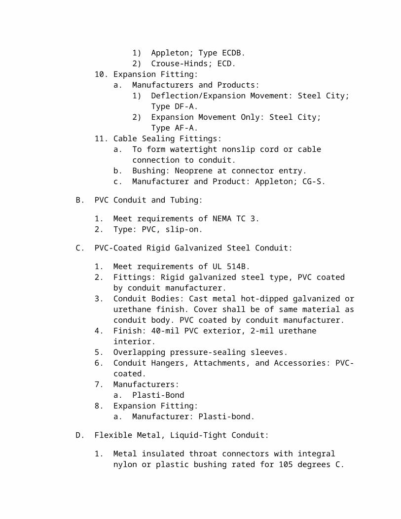
9. Drain/Breather Fitting:a. Manufacturers and Products:
1) Appleton; Type ECDB.2) Crouse-Hinds; ECD.
10. Expansion Fitting:a. Manufacturers and Products:
1) Deflection/Expansion Movement: Steel City; Type DF-A.2) Expansion Movement Only: Steel City; Type AF-A.
11. Cable Sealing Fittings:a. To form watertight nonslip cord or cable connection to conduit.b. Bushing: Neoprene at connector entry.c. Manufacturer and Product: Appleton; CG-S.
B. PVC Conduit and Tubing:
1. Meet requirements of NEMA TC 3.2. Type: PVC, slip-on.
C. PVC-Coated Rigid Galvanized Steel Conduit:
1. Meet requirements of UL 514B.2. Fittings: Rigid galvanized steel type, PVC coated by conduit manufacturer.3. Conduit Bodies: Cast metal hot-dipped galvanized or urethane finish. Cover
shall be of same material as conduit body. PVC coated by conduit manufacturer.
4. Finish: 40-mil PVC exterior, 2-mil urethane interior.5. Overlapping pressure-sealing sleeves.6. Conduit Hangers, Attachments, and Accessories: PVC-coated.7. Manufacturers:
a. Plasti-Bond8. Expansion Fitting:
a. Manufacturer: Plasti-bond.
D. Flexible Metal, Liquid-Tight Conduit:
1. Metal insulated throat connectors with integral nylon or plastic bushing rated for 105 degrees C.
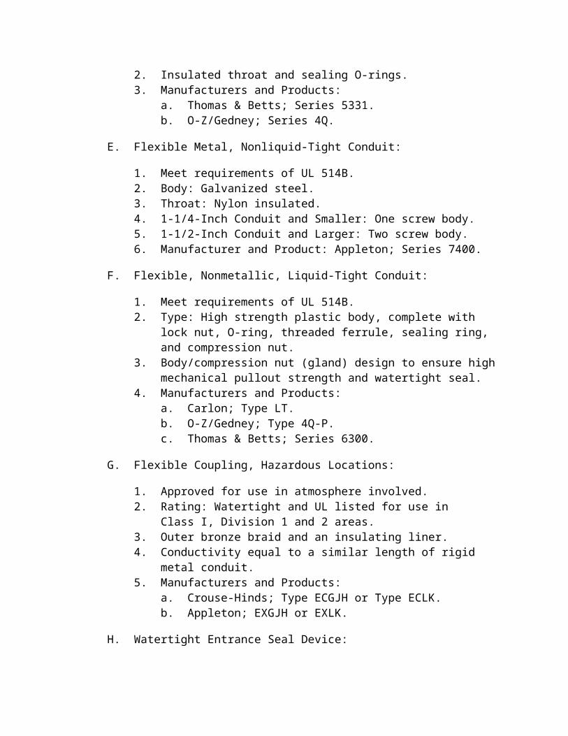
2. Insulated throat and sealing O-rings.

3. Manufacturers and Products:a. Thomas & Betts; Series 5331.b. O-Z/Gedney; Series 4Q.
E. Flexible Metal, Nonliquid-Tight Conduit:
1. Meet requirements of UL 514B.2. Body: Galvanized steel.3. Throat: Nylon insulated.4. 1-1/4-Inch Conduit and Smaller: One screw body.5. 1-1/2-Inch Conduit and Larger: Two screw body.6. Manufacturer and Product: Appleton; Series 7400.
F. Flexible, Nonmetallic, Liquid-Tight Conduit:
1. Meet requirements of UL 514B.2. Type: High strength plastic body, complete with lock nut, O-ring, threaded
ferrule, sealing ring, and compression nut.3. Body/compression nut (gland) design to ensure high mechanical pullout
strength and watertight seal.4. Manufacturers and Products:
a. Carlon; Type LT.b. O-Z/Gedney; Type 4Q-P.c. Thomas & Betts; Series 6300.
G. Flexible Coupling, Hazardous Locations:
1. Approved for use in atmosphere involved.2. Rating: Watertight and UL listed for use in Class I, Division 1 and 2 areas.3. Outer bronze braid and an insulating liner.4. Conductivity equal to a similar length of rigid metal conduit.5. Manufacturers and Products:
a. Crouse-Hinds; Type ECGJH or Type ECLK.b. Appleton; EXGJH or EXLK.
H. Watertight Entrance Seal Device:
1. New Construction:a. Material: Oversized sleeve, malleable iron body with sealing ring,
pressure ring, grommet seal, and pressure clamp.b. Manufacturer and Product: O-Z/Gedney; Type FSK or Type WSK, as
required.2. Cored-Hole Application:
a. Material: Assembled dual pressure disks, neoprene sealing ring, and membrane clamp.
b. Manufacturer and Product: O-Z/Gedney; Series CSM.
2.03 OUTLET AND DEVICE BOXES
A. Sheet Steel: One-piece drawn type, zinc-plated or cadmium-plated.
B. Cast Aluminum:
1. Material:a. Box: Cast, copper-free aluminum.b. Cover: Gasketed, weatherproof, cast copper-free aluminum with
stainless steel screws.2. Hubs: Threaded.3. Lugs: Cast mounting.4. Manufacturers and Products, Nonhazardous Locations:
a. Crouse-Hinds; Type FS-SA or Type FD-SA.b. Appleton; Type FS or Type FD.c. Killark.
5. Manufacturers and Products, Hazardous Locations:a. Crouse-Hinds; Type GUA-SA.b. Appleton; Type GR.
C. PVC-Coated Cast Metal:
1. Type: One-piece.2. Material: Malleable iron, cast ferrous metal, or cast aluminum.3. Coating:
a. Exterior Surfaces: 40-mil PVC.b. Interior Surfaces: 2-mil urethane.
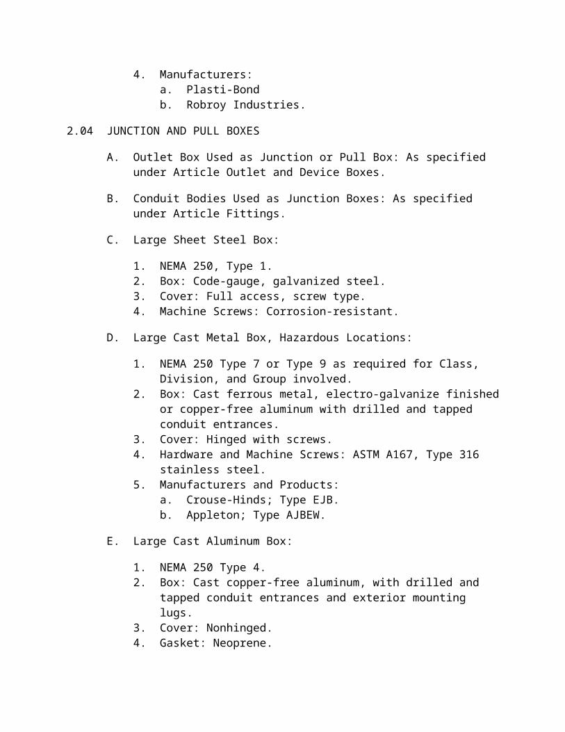
4. Manufacturers:a. Plasti-Bondb. Robroy Industries.
2.04 JUNCTION AND PULL BOXES
A. Outlet Box Used as Junction or Pull Box: As specified under Article Outlet and Device Boxes.
B. Conduit Bodies Used as Junction Boxes: As specified under Article Fittings.
C. Large Sheet Steel Box:
1. NEMA 250, Type 1.2. Box: Code-gauge, galvanized steel.3. Cover: Full access, screw type.4. Machine Screws: Corrosion-resistant.
D. Large Cast Metal Box, Hazardous Locations:
1. NEMA 250 Type 7 or Type 9 as required for Class, Division, and Group involved.
2. Box: Cast ferrous metal, electro-galvanize finished or copper-free aluminum with drilled and tapped conduit entrances.
3. Cover: Hinged with screws.4. Hardware and Machine Screws: ASTM A167, Type 316 stainless steel.5. Manufacturers and Products:
a. Crouse-Hinds; Type EJB.b. Appleton; Type AJBEW.
E. Large Cast Aluminum Box:
1. NEMA 250 Type 4.2. Box: Cast copper-free aluminum, with drilled and tapped conduit entrances
and exterior mounting lugs.3. Cover: Nonhinged.4. Gasket: Neoprene.5. Hardware and Machine Screws: ASTM A167, Type 316 stainless steel.6. Manufacturers and Products, Surface Mounted Type:
a. Crouse-Hinds; Series W-SA.b. O-Z/Gedney; Series YS-A, YL-A.c. Killark.
F. Large Stainless Steel Box:
1. NEMA 250 Type 4X.2. Box: 14-gauge, ASTM A240/A240M, Type 316 stainless steel, with white
enamel painted interior mounting panel.3. Cover: Hinged.4. Hardware and Machine Screws: ASTM A167, Type 316 stainless steel.5. Manufacturers:
a. Hoffman Engineering Co.b. Robroy Industries.c. Wiegman.
G. Large Steel Box:
1. NEMA 250 Type 3R.2. Box: 10-gauge steel, with white enamel painted interior and gray primed
exterior, over phosphated surfaces. Provide gray finish as approved by Engineer.
3. Cover: Hinged with clamps.4. Hardware and Machine Screws: ASTM A167, Type 316 stainless steel.5. Manufacturers:
a. Hoffman Engineering Co.b. Robroy Industries.c. Wiegman.
H. Large Nonmetallic Box:

1. NEMA 250 Type 4X.2. Box: High-impact, fiberglass-reinforced polyester or engineered
thermoplastic, with stability to high heat.3. Cover: Hinged with clamps.4. Hardware and Machine Screws: ASTM A167, Type 316 stainless steel.5. Conduit hubs and mounting lugs.6. Manufacturers and Products:
a. Crouse-Hinds; Type NJB.b. Carlon; Series N, C, or H.c. Robroy Industries.
I. Concrete Box, Nontraffic Areas:
1. Box: Reinforced, cast concrete with extension.2. Cover: Steel diamond plate with locking bolts.3. Cover Marking: ELECTRICAL, TELEPHONE, or as shown.4. Size: 10 inches by 17 inches, minimum.5. Manufacturers and Products:
a. Utility Vault Co.; Series 36-1017.b. Christy, Concrete Products, Inc.; N9.c. Quazite; “PG” Style.
J. Concrete Box, Traffic Areas:
1. Box: Reinforced, cast concrete with extension and bottom slab.2. Cover: Steel checked plate; H/20 loading with screw down.3. Cover Marking: ELECTRICAL, TELEPHONE, or as shown.4. Manufacturers and Products:
a. Christy, Concrete Products, Inc.; B1017BOX.b. Utility Vault Co.; 3030 SB.
2.05 TERMINAL JUNCTION BOX
A. Cover: Hinged, unless otherwise shown.
B. Interior Finish: Paint with white enamel or lacquer.
C. The Wet Well Interface Terminal Junction Box per DPW Standard Details with size adjusted per Project specific sizing.
D. Terminal Blocks:
1. Separate connection point for each conductor entering or leaving box.2. Spare Terminal Points: 25 percent, minimum.
2.06 PRECAST MANHOLES AND HANDHOLES
A. Concrete Strength: Minimum, 3,000 psi compressive, in 28 days.
B. Loading: AASHTO, H-20 in accordance with ASTM C857.
C. Access: Provide cast concrete 6-inch or 12-inch risers and access hole adapters between top of manhole and finished grade at required elevations.
D. Drainage:
1. Slope floors toward drain points, leaving no pockets or other nondraining areas.
2. Provide drainage outlet or sump at low point of floor constructed with a heavy, cast iron, slotted or perforated hinged cover, and a minimum 4-inch outlet and outlet pipe.
E. Raceway Entrances:
1. Provide on all four sides.2. Provide knockout panels or precast individual raceway openings.3. At entrances where raceways are to be installed by others, provide
minimum 12-inch-high by 24-inch-wide knockout panels for future raceway installation.
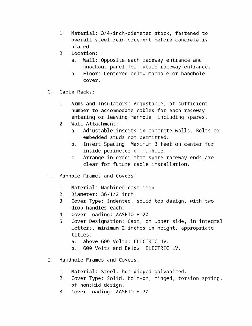
F. Embedded Pulling Iron:
1. Material: 3/4-inch-diameter stock, fastened to overall steel reinforcement before concrete is placed.
2. Location:a. Wall: Opposite each raceway entrance and knockout panel for future
raceway entrance.b. Floor: Centered below manhole or handhole cover.
G. Cable Racks:
1. Arms and Insulators: Adjustable, of sufficient number to accommodate cables for each raceway entering or leaving manhole, including spares.
2. Wall Attachment:a. Adjustable inserts in concrete walls. Bolts or embedded studs not
permitted.b. Insert Spacing: Maximum 3 feet on center for inside perimeter of
manhole.c. Arrange in order that spare raceway ends are clear for future cable
installation.
H. Manhole Frames and Covers:
1. Material: Machined cast iron.2. Diameter: 36-1/2 inch.3. Cover Type: Indented, solid top design, with two drop handles each.4. Cover Loading: AASHTO H-20.

5. Cover Designation: Cast, on upper side, in integral letters, minimum 2 inches in height, appropriate titles:a. Above 600 Volts: ELECTRIC HV.b. 600 Volts and Below: ELECTRIC LV.
I. Handhole Frames and Covers:
1. Material: Steel, hot-dipped galvanized.2. Cover Type: Solid, bolt-on, hinged, torsion spring, of nonskid design.3. Cover Loading: AASHTO H-20.4. Cover Designation: Burn by welder, on upper side in integral letters,
minimum 2 inches in height, appropriate titles:a. 600 Volts and Below: ELECTRIC LV.
J. Hardware: Steel, hot-dip galvanized.
K. Furnish knockout for ground rod in each handhole and manhole.
L. Manufacturers:
1. Utility Vault Co.2. Penn-Cast Products, Inc.
2.07 ACCESSORIES
A. Duct Bank Spacers:
1. Modular Type:a. Nonmetallic, interlocking, for multiple conduit sizes.b. Suitable for all types of conduit.c. Manufacturers:
1) Underground Device, Inc.2) Carlon.
2. Template Type:a. Nonmetallic, custom made one-piece spacers.b. Suitable for all types of conduit.c. Material: HDPE or polypropylene, 1/2-inch minimum thickness.d. Conduit openings cut 1 inch larger than conduit outside diameter.e. Additional openings for stake-down, rebar, and concrete flow through
as required.f. Manufacturer and Product: SP Products; Quik Duct.
B. Identification Devices:
1. Raceway Tags:a. Material: Permanent, nonferrous metal.b. Shape: Round.c. Raceway Designation: Pressure stamped, embossed, or engraved.

d. Tags relying on adhesives or taped-on markers not permitted.2. Warning Tape:
a. Material: Polyethylene, 4-mil gauge with detectable strip.b. Color: Red.c. Width: Minimum 6 inches.d. Designation: Warning on tape that electric circuit is located below
tape.e. Identifying Letters: Minimum 1-inch-high permanent black lettering
imprinted continuously over entire length.f. Manufacturers and Products:
1) Panduit; Type HTDU.2) Reef Industries; Terra Tape.
3. Buried Raceway Marker:a. Material: Sheet bronze, consisting of double-ended arrows, straight
for straight runs and bent at locations where runs change direction.b. Designation: Engrave to depth of 3/32 inch; ELECTRIC CABLES, in
letters 1/4-inch high.c. Minimum Dimension: 1/4 inch thick, 10 inches long, and 3/4 inch
wide.
C. Wraparound Duct Band:
1. Material: Heat-shrinkable, cross-linked polyolefin, precoated with hot-melt adhesive.
2. Width: 50 mm minimum.3. Manufacturer and Product: Raychem; Type TWDB.
PART 3 EXECUTION
3.01 GENERAL
A. Conduit and tubing sizes shown are based on use of copper conductors. Reference Section 16120 (Design Engineer to Verify Reference), Conductors, concerning conduit sizing for aluminum conductors.
B. Comply with NECA Installation Standards.
C. Crushed or deformed raceways not permitted.
D. Maintain raceway entirely free of obstructions and moisture.
E. Immediately after installation, plug or cap raceway ends with watertight and dust-tight seals until time for pulling in conductors.
F. Aluminum Conduit: Do not install in direct contact with concrete. Install in PVC sleeve or cored hole through concrete walls and slabs.

G. Sealing Fittings: Provide drain seal in vertical raceways where condensate may collect above sealing fitting.
H. Avoid moisture traps where possible. When unavoidable in exposed conduit runs, provide junction box and drain fitting at conduit low point.
I. Group raceways installed in same area.
J. Follow structural surface contours when installing exposed raceways. Avoid obstruction of passageways.
K. Run exposed raceways parallel or perpendicular to walls, structural members, or intersections of vertical planes.
L. Block Walls: Do not install raceways in same horizontal course or vertical cell with reinforcing steel.
M. Install watertight fittings in outdoor, underground, or wet locations.
N. Paint threads and cut ends, before assembly of fittings, aluminum conduit and PVC-coated rigid galvanized steel conduit installed in exposed or damp locations with zinc-rich paint, liquid galvanizing compound or anti-galling compound as appropriate for the material.
O. Metal conduit shall be reamed, burrs removed, and cleaned before installation of conductors, wires, or cables.
P. Do not install raceways in concrete equipment pads, foundations, or beams without Engineer approval.
Q. Horizontal raceways installed under floor slabs shall lie completely under slab, with no part embedded within slab. Where raceways under slab are concrete encased, on vertical transitions, tie the reinforcing steel from the concrete encasement with the slab reinforcement to eliminate differential movement.
R. Install concealed, embedded, and buried raceways so that they emerge at right angles to surface and have no curved portion exposed.
3.02 REUSE OF EXISTING CONDUITS
A. Where Drawings indicate existing conduits may be reused, they may be reused only where they meet the following criteria.
1. Conduit is in useable condition with no deformation, corrosion, or damage to exterior surface.
2. Conduit is sized per the NEC.3. Conduit is of the type specified in Contract Documents.4. Conduit is supported as specified in Contract Documents.
5. Approved by the Engineer.
B. Conduit shall be reamed with wire brush, then with a mandrel approximately 1/4 inch smaller than raceway inside diameter then cleaned prior to pulling new conductors.
3.03 INSTALLATION IN CAST-IN-PLACE STRUCTURAL CONCRETE
A. Minimum Cover: 2 inches, including fittings.
B. Conduit placement shall not require changes in reinforcing steel location or configuration.
C. Provide nonmetallic support during placement of concrete to ensure raceways remain in position.
D. Conduit larger than 1 inch shall not be embedded in concrete slabs, walls, foundations, columns, or beams unless approved by Engineer.
E. Slabs and Walls (Requires Engineer Approval):
1. Trade size of conduit not to exceed one-fourth of slab or wall thickness.2. Install within middle two-fourths of slab or wall.3. Separate conduit less than 2-inch trade size by a minimum ten times conduit
trade size, center-to-center, unless otherwise shown.4. Separate conduit 2-inch and greater trade size by a minimum eight times
conduit trade size, center-to-center, unless otherwise shown.5. Cross conduit at an angle greater than 45 degrees, with minimum separation
of 1 inch.6. Separate conduit by a minimum six times the outside dimension of
expansion/deflection fittings at expansion joints.7. Conduit shall not be installed below the maximum water surface elevation
in walls of water holding structures.
F. Columns and Beams (Requires Engineer Approval):
1. Trade size of conduit not to exceed one-fourth of beam thickness.2. Conduit cross-sectional area not to exceed 4 percent of beam or column
cross section.
3.04 CONDUIT APPLICATION
A. Diameter: Minimum 3/4 inch.
B. Exterior, Exposed:
1. Rigid aluminum.2. PVC-coated rigid galvanized steel.
C. Interior, Exposed: Rigid aluminum.
D. Interior, Concealed (Not Embedded in Concrete): Rigid aluminum.
E. Aboveground, Embedded in Concrete Walls, Ceilings, or Floors: PVC-coated rigid galvanized steel.
F. Direct Earth Burial: PVC-coated rigid galvanized steel.
G. Concrete-Encased Ductbank:
1. PVC Schedule 40. (Except where prohibited elsewhere in Contract Documents)
2. PVC-coated rigid galvanized steel.
H. Under Slabs-On-Grade or Equipment Renovating Pads:
1. PVC Schedule 40 in reinforced concrete-encased ductbank. (Except where prohibited elsewhere in Contract Documents)
2. PVC-coated rigid galvanized steel in reinforced concrete-encased ductbank.
I. Transition from Underground or Concrete Embedded to Exposed: PVC-coated rigid galvanized steel conduit.
J. Exterior Light Pole Foundations: PVC-coated rigid galvanized steel conduit.
K. Corrosive Areas: PVC-coated rigid galvanized steel.
L. Hazardous Gas Areas:
1. PVC-coated rigid galvanized steel.2. Rigid aluminum.
3.05 FLEXIBLE CONNECTIONS
A. For motors, wall or ceiling mounted fans and unit heaters, dry type transformers, electrically operated valves, instrumentation, and other locations approved by Engineer where flexible connection is required to minimize vibration:
1. Conduit Size 4 Inches or Less: Flexible, liquid-tight conduit.2. Conduit Size Over 4 Inches: Nonflexible.3. Wet or Corrosive Areas: Flexible, nonmetallic or flexible metal liquid-tight.4. Dry Areas: Flexible, metallic liquid-tight.5. Hazardous Areas: Flexible coupling suitable for Class I, Division 1 and 2
areas.
B. Suspended Lighting Fixtures in Dry Areas: Flexible steel, nonliquid-tight conduit.
C. Outdoor Areas, Process Areas Exposed to Moisture, and Areas Required to be Oiltight and Dust-Tight: Flexible metal, liquid-tight conduit.
D. Flexible Conduit Length: 18 inches minimum, 60 inches maximum; sufficient to allow movement or adjustment of equipment.
3.06 PENETRATIONS
A. Make at right angles, unless otherwise shown.
B. Notching or penetration of structural members, including footings and beams, not permitted.
C. Apply heat shrinkable tubing to metallic conduit protruding through concrete floor slabs to a point 2 inches above and 2 inches below concrete surface.
D. Entering Structures:
1. General: Seal raceway at first box or outlet with oakum or expandable plastic compound to prevent entrance of gases or liquids from one area to another.
2. Concrete Roof or Membrane Waterproofed Wall or Floor:a. Provide a watertight seal.b. Without Concrete Encasement: Install watertight entrance seal device
on each side.c. With Concrete Encasement: Install watertight entrance seal device on
accessible side.d. Securely anchor malleable iron body of watertight entrance seal
device into construction with one or more integral flanges.e. Secure membrane waterproofing to watertight entrance seal device in
a permanent, watertight manner.3. Heating, Ventilating, and Air Conditioning Equipment:
a. Penetrate equipment in area established by manufacturer.b. Terminate conduit with flexible metal or nonmetallic conduit at
junction box or condulet attached to exterior surface of equipment prior to penetrating equipment.
c. Seal penetration with Type 5 sealant, as specified in Section 07900 (Design Engineer to Verify Reference), Joint Sealants.
4. Corrosive-Sensitive Areas:a. Seal conduit entering equipment panel boards and field panels
containing electronic equipment.b. Seal penetration with Type 5 sealant, as specified in Section 07900
(Design Engineer to Verify Reference), Joint Sealants.5. Existing or Precast Wall (Underground): Core drill wall and install
watertight entrance seal device.6. Non-waterproofed Wall or Floor:

a. Tie the reinforcing steel from concrete encased ductbank to wall or floor reinforcing steel and pour ductbank to make contact with floor or wall to prevent differential movement between the structure and ductbank.
7. Manholes and Handholes:a. Metallic Raceways: Provide insulated grounding bushings.b. Nonmetallic Raceways: Provide bell ends flush with wall.c. Install such that raceways enter as near as possible to one end of wall,
unless otherwise shown.
3.07 SUPPORT
A. Support from structural members only, at intervals not exceeding NFPA 70 requirements. Do not exceed 8 feet in any application. Do not support from piping, pipe supports, or other raceways.
B. Multiple Adjacent Raceways: Provide ceiling trapeze. For trapeze-supported conduit, allow 2 percent extra space for future conduit.
C. Application/Type of Conduit Strap:
1. Aluminum Conduit: Stainless steel.2. PVC-Coated Rigid Galvanized Steel Conduit: PVC-coated metal.3. Nonmetallic Conduit: Nonmetallic or PVC-coated metal.
D. Provide and attach wall brackets, strap hangers, or ceiling trapeze as follows:
1. Wood: Wood screws.2. Hollow Masonry Units: Toggle bolts.3. Concrete or Brick: Expansion shields, or threaded studs driven in by
powder charge, with lock washers and nuts.4. Steelwork: Machine screws.5. Location/Type of Hardware:
a. Dry, Noncorrosive Areas: Galvanized.b. Wet, Noncorrosive Areas: Stainless steel.c. Corrosive Areas: Stainless steel.
E. Nails or wooden plugs inserted in concrete or masonry for attaching raceway not permitted. Do not weld raceways or pipe straps to steel structures. Do not use wire in lieu of straps or hangers.
F. Support aluminum conduit on concrete surfaces with stainless steel or nonmetallic spacers, or aluminum or nonmetallic framing channel.
3.08 BENDS
A. Install concealed raceways with a minimum of bends in the shortest practical distance.

B. Make bends and offsets of longest practical radius. Bends in conduits and ducts being installed for fiber optic cables shall be not less than 20 times cable diameter, 15 inches minimum.
C. Install with symmetrical bends or cast metal fittings.
D. Avoid field-made bends and offsets, but where necessary, make with acceptable hickey or bending machine. Do not heat metal raceways to facilitate bending.
E. Make bends in parallel or banked runs from same center or centerline with same radius so that bends are parallel.
F. Factory elbows may be installed in parallel or banked raceways if there is change in plane of run, and raceways are same size.
G. PVC Conduit:
1. Bends 30 Degrees and Larger: Provide factory-made elbows.2. Bends 45-Degrees and Larger: Provide PVC-coated galvanized rigid steel
bends or elbows.3. Use manufacturer’s recommended method for forming smaller bends.
H. Flexible Conduit: Do not make bends that exceed allowable conductor bending radius of cable to be installed or that significantly restricts conduit flexibility.
3.09 EXPANSION/DEFLECTION FITTINGS
A. Provide on exposed or embedded raceways at structural expansion joints and in long tangential runs.
B. Provide expansion/deflection joints for 25 - 50 degrees F maximum temperature variation on exposed raceways.
C. Install in accordance with manufacturer’s instructions.
3.10 PVC CONDUIT
A. Solvent Welding:
1. Apply manufacturer recommended solvent to joints.2. Install in order that joint is watertight.
B. Adapters:
1. PVC to Metallic Fittings: PVC terminal type.2. PVC to PVC-Coated Rigid Galvanized Steel: PVC female adapter.
C. Belled-End Conduit: Bevel unbelled end of joint prior to joining.

3.11 PVC-COATED RIGID GALVANIZED STEEL CONDUIT
A. Install in accordance with manufacturer’s instructions.
B. Tools and equipment used in cutting, bending, threading and installation of PVC-coated rigid galvanized steel conduit shall be designed to limit damage to PVC coating.
C. Provide PVC boot to cover exposed threading.
3.12 TERMINATION AT ENCLOSURES
A. Cast Metal Enclosure: Install manufacturer’s premolded insulating sleeve inside metallic conduit terminating in threaded hubs.
B. Nonmetallic, Cabinets, and Enclosures:
1. Terminate conduit in threaded conduit hubs, maintaining enclosure integrity.
2. Metallic Conduit: Provide ground terminal for connection to maintain continuity of ground system.
C. Sheet Metal Boxes, Cabinets, and Enclosures:
1. General:a. Install insulated bushing on ends of conduit where grounding is not
required.b. Provide insulated throat when conduit terminates in sheet metal boxes
having threaded hubs.c. Utilize threaded hubs on sides and bottom of NEMA 3R and
NEMA 12 enclosures.d. Terminate conduits at threaded hubs at the tops of NEMA 3R and
NEMA 12 boxes and enclosures.e. Terminate conduits at threaded conduit hubs at NEMA 4 and
NEMA 4X boxes and enclosures.2. Rigid Aluminum Conduit:
a. Provide threaded conduit hub where conduit terminates at enclosures that do not have a precast hub.
b. Install grounding lug on threaded conduit hub.c. Provide bonding jumper from grounding bushing to equipment
ground bus or ground pad.3. Flexible Metal Conduit: Provide two screw type, insulated, malleable iron
connectors.4. Flexible, Nonmetallic Conduit: Provide nonmetallic, liquid-tight strain
relief connectors.5. PVC-Coated Rigid Galvanized Steel Conduit: Provide PVC-coated, liquid-
tight, threaded conduit hub.

D. Motor Control Center, Switchboard , Switchgear , and Free-Standing Enclosures:
1. Terminate metal conduit entering bottom with grounding bushing; provide grounding jumper extending to equipment ground bus or grounding pad.
3.13 UNDERGROUND RACEWAYS
A. Grade: Maintain minimum grade of 4 inches in 100 feet, either from one manhole, handhole, or pull box to the next, or from a high point between them, depending on surface contour.
B. Cover: Maintain minimum 24-inch cover above conduit and concrete encasement, unless otherwise shown.
C. Make routing changes as necessary to avoid obstructions or conflicts.
D. Couplings: In multiple conduit runs, stagger so couplings in adjacent runs are not in same transverse line.
E. Union type fittings not permitted.
F. Spacers:
1. Provide preformed, nonmetallic spacers designed for such purpose, to secure and separate parallel conduit runs in a trench or concrete encasement.
2. Install at intervals not greater than that specified in NFPA 70 for support of the type conduit used, but in no case greater than 10 feet.
G. Support conduit so as to prevent bending or displacement during backfilling or concrete placement.
H. Transition from Underground to Exposed: PVC-coated rigid galvanized steel conduit.
I. Installation with Other Piping Systems:
1. Crossings: Maintain minimum 12-inch vertical separation.2. Parallel Runs: Maintain minimum 12-inch separation.3. Installation over valves or couplings not permitted.
J. Provide structural interface to prevent differential movement between reinforced concrete encased ductbank and building or structure where conduit makes transition into building or structure, unless show otherwise.

K. Concrete Encasement:
1. As specified in Section 03300, Cast-in-Place Concrete (Design Engineer to Verify Reference or Replace with Concrete Specification).
2. Concrete Color: Red.
L. Backfill:
1. As specified in Section 02320 Trench Backfill (Design Engineer to Verify Reference). Controlled low strength fill is an acceptable bedding and pipe zone material. Backfill material to within 12 inches of surface.
2. Do not backfill until inspected by Engineer
3.14 UNDER SLAB REINFORCED CONCRETE ENCASED RACEWAYS
A. Make routing changes as necessary to avoid obstructions or conflicts.
B. Support raceways so as to prevent bending or displacement during concrete placement.
C. Install raceways with no part embedded within slab and with no interference with slab on grade construction.
D. Raceway spacing, in a single layer or multiple layers:
1. 3 inches clear between adjacent 2-inch or larger raceway.2. 2 inches clear between adjacent 1-1/2-inch or smaller raceway.
E. Multiple Layers of Raceways: Install under slab on grade in trench below backfill zone maintaining consistent use of reinforcement spacing. Provide backfill material between encased ductbanks, as specified in Section 02320, Trench Backfill (Design Engineer to Verify Reference).
F. Under slab raceways and associated reinforced concrete encasement that emerge from below slab to top of slab as exposed, shall be located to avoid conflicts with structural slab rebar. Coordinate raceway stub ups with location of structural rebar. For each lateral and vertical rebar in the emerging conduit encasement, provide a minimum of 14-inches of exposed rebar to allow concrete encasement of ductbank to be tied to the slab above to prevent any differential movement.
G. Fittings:
1. Union type fittings are not permitted.2. Couplings: In multiple raceway runs, stagger so couplings in adjacent runs
are not in same traverse line.
3.15 OUTLET AND DEVICE BOXES
A. General:
1. Install plumb and level.2. Install suitable for conditions encountered at each outlet or device in wiring
or raceway system, sized to meet NFPA 70 requirements.3. Open no more knockouts in sheet steel device boxes than are required; seal
unused openings.
B. Size:
1. Depth: Minimum 2 inches, unless otherwise required by structural conditions. Box extensions not permitted.a. Hollow Masonry Construction: Install with sufficient depth such that
conduit knockouts or hubs are in masonry void space.2. Ceiling Outlet: Minimum 4-inch octagonal device box, unless otherwise
required for installed fixture.3. Switch and Receptacle: Minimum 2-inch by 4-inch device box.
C. Locations:
1. Drawing locations are approximate.2. To avoid interference with mechanical equipment or structural features,
relocate outlets as directed by Engineer.3. Light Fixture: Install in symmetrical pattern according to room layout,
unless otherwise shown.
D. Mounting Height:
1. General:a. Dimensions given to centerline of box.b. Where specified heights do not suit building construction or finish,
adjust up or down to avoid interference.c. Do not straddle CMU block or other construction joints.
2. Light Switch:a. 48 inches above floor.b. When located next to door, install on lock side of door.
3. Thermostat: 54 inches above floor.4. Convenience Receptacle:
a. General Interior Areas: 15 inches above floor.b. Industrial Areas, Workshops: 48 inches above floor.c. Outdoor Areas: 36 inches above finished grade.
5. Special-Purpose Receptacle 36 inches above floor or as shown.6. Switch, Motor Starting: 48 inches above floor, unless otherwise indicated
on Drawings.
E. Flush Mounted:
1. Install with concealed conduit.
2. Install proper type extension rings or plaster covers to make edges of boxes flush with finished surface.
3. Holes in surrounding surface shall be no larger than required to receive box.
F. Supports:
1. Support boxes independently of conduit by attachment to building structure or structural member.
2. Install bar hangers in frame construction or fasten boxes directly as follows:a. Wood: Wood screws.b. Concrete or Brick: Bolts and expansion shields.c. Hollow Masonry Units: Toggle bolts.d. Steelwork: Machine screws.
3. Threaded studs driven in by powder charge and provided with lock washers and nuts are acceptable in lieu of expansion shields.
4. Provide plaster rings where necessary.5. Boxes embedded in concrete or masonry need not be additionally
supported.G. Boxes Supporting Fixtures: Provide means of attachment with adequate strength
to support fixture.
3.16 JUNCTION AND PULL BOXES
A. General:
1. Install plumb and level.2. Installed boxes shall be accessible.3. Do not install on finished surfaces.4. Use outlet boxes as junction and pull boxes wherever possible and allowed
by applicable codes.5. Use conduit bodies as junction and pull boxes where no splices are required
and allowed by applicable codes.6. Install pull boxes where necessary in raceway system to facilitate conductor
installation.7. Install where shown and where necessary to terminate, tap-off, or redirect
multiple conduit runs.8. Install in conduit runs at least every 150 feet or after the equivalent of three
right-angle bends.
B. Flush Mounted:
1. Install with concealed conduit.2. Holes in surrounding surface shall be no larger than required to receive box.3. Make edges of boxes flush with final surface.
C. Mounting Hardware:
1. Noncorrosive Dry Areas: Galvanized.
2. Noncorrosive Wet Areas: Stainless steel.3. Corrosive Areas: Stainless steel.
D. Supports:
1. Support boxes independently of conduit by attachment to building structure or structural member.
2. Install bar hangers in frame construction or fasten boxes directly as follows:a. Wood: Wood screws.b. Concrete or Brick: Bolts and expansion shields.c. Hollow Masonry Units: Toggle bolts.d. Steelwork: Machine screws.
3. Threaded studs driven in by powder charge and provided with lock washers and nuts are acceptable in lieu of expansion shields.
4. Boxes embedded in concrete or masonry need not be additionally supported.
E. At or Below Grade:
1. Install boxes for below grade conduit flush with finished grade in locations outside of paved areas, roadways, or walkways.
2. If adjacent structure is available, box may be mounted on structure surface just above finished grade in accessible but unobtrusive location.
3. Obtain Engineer’s written acceptance prior to installation in paved areas, roadways, or walkways.
4. Use boxes and covers suitable to support anticipated weights.
F. Location/Type:
1. Indoor, Dry: NEMA 250, Type 1.2. Indoor and Outdoor, Wet: NEMA 250, Type 4.3. Indoor and Outdoor, Wet and Corrosive: NEMA 250, Type 4X, stainless
steel.4. Indoor and Outdoor, Wet, Dust, or Oil: NEMA 250, Type 13.5. Indoor and Outdoor, Hazardous: NEMA 250, Type 7 and Type 9.6. Underground Conduit: Concrete.7. Corrosive: NEMA 250, Type 4X, stainless steel.8. Outdoor, Where Indicated Weatherproof (WP): NEMA 250, Type 3R.9. Industrial Use in Areas Not Otherwise Classified: NEMA 250, Type 12,
unless otherwise shown.
G. Install Drain/breather fittings in NEMA 250 Type 4 and Type 4X enclosures.
3.17 MANHOLES AND HANDHOLES

A. Excavate, shore, brace, backfill, and final grade in accordance with Section 02315 (Design Engineer to Verify Reference), Excavation, and Section 02320 (Design Engineer to Verify Reference), Trench Backfill.
B. Do not install until final raceway grading has been determined.
C. Install such that raceway enters at nearly right angle and as near as possible to end of wall, unless otherwise shown.
D. Grounding: As specified in Section 16060 (Design Engineer to Verify Reference), Grounding and Bonding for Electrical Systems.
E. Identification: Field stamp covers with manhole or handhole number as shown. Stamped numbers to be 1-inch minimum height.
3.18 EMPTY RACEWAYS
A. Provide permanent, removable cap over each end.
B. Provide PVC plug with pull tab for underground raceways with end bells.
C. Provide nylon pull cord.
D. Identify, as specified in Article Identification Devices, with waterproof tags attached to pull cord at each end, and at intermediate pull point.
3.19 IDENTIFICATION DEVICES
A. Raceway Tags:
1. Identify origin and destination.2. For exposed raceways, install tags at each terminus, near midpoint, and at
minimum intervals of every 50 feet, whether in ceiling space or surface mounted.
3. Install tags at each terminus for concealed raceways.4. Provide noncorrosive wire for attachment.
B. Warning Tape: Install approximately 12 inches above underground or concrete-encased raceways. Align parallel to, and within 12 inches of, centerline of run.
C. Buried Raceway Marker:
1. Install at grade to indicate direction of underground raceway.2. Install at bends and at intervals not exceeding 100 feet in straight runs.3. Embed and secure to top of concrete base, sized 14 inches long, 6 inches
wide, and 8 inches deep; top set flush with finished grade.
3.20 PROTECTION OF INSTALLED WORK
A. Protect products from effects of moisture, corrosion, and physical damage during construction.
B. Provide and maintain manufactured watertight and dust-tight seals over conduit openings during construction. Duct tape is not acceptable.
C. Touch up painted conduit threads after assembly to cover nicks or scars.
D. Touch up coating damage to PVC-coated conduit with patching compound approved by manufacturer. Compound shall be kept refrigerated according to manufacturers’ instructions until time of use.
3.21 SUPPLEMENTS
A. The supplements listed below, following “END OF SECTION,” is part of this Specification.
1. “Concrete Encased Duct Termination with Structural Concrete” detail.2. “Duct Bank/Conduit Transition and Support” detail.3. “Duct Bank” details (two pages).
END OF SECTION