Options Guide - English - Fujitsumanuals.ts.fujitsu.com/file/9435/bx924s2-og-en.pdf · Documents...
52
Options Guide - English PRIMERGY BX924 S2 Server Blade Options Guide March 2011
Transcript of Options Guide - English - Fujitsumanuals.ts.fujitsu.com/file/9435/bx924s2-og-en.pdf · Documents...

Options Guide - English
PRIMERGY BX924 S2Server Blade Options Guide
March 2011

Comments… Suggestions… Corrections…The User Documentation Department would like toknow your opinion of this manual. Your feedback helpsus optimize our documentation to suit your individual needs.
Feel free to send us your comments by e-mail to [email protected].
Certified documentation according to DIN EN ISO 9001:2008To ensure a consistently high quality standard anduser-friendliness, this documentation was created tomeet the regulations of a quality management system which complies with the requirements of the standardDIN EN ISO 9001:2008.
cognitas. Gesellschaft für Technik-Dokumentation mbHwww.cognitas.de
Copyright and Trademarks
© c
ogni
tas.
Ges
ells
chft
für
Tech
nik-
Dok
ume
ntat
ion
mb
H 2
011
P
fad:
C:\P
rogr
am
me\
FC
T\ti
m_a
pp\ti
m_l
oca
l\wor
k\W
ALT
ER
\OB
J_D
OK
U-7
689-
002
.fm
Copyright © 2011 Fujitsu Technology Solutions GmbH.
All rights reserved.Delivery subject to availability; right of technical modifications reserved.
All hardware and software names used are trademarks of their respective manufacturers.
– The contents of this manual may be revised without prior notice.
– Fujitsu assumes no liability for damages to third party copyrights or other rights arising from the use of any information in this manual.
– No part of this manual may be reproduced in any without the prior written permission of Fujitsu.
Microsoft, Windows, Windows Server, and Hyper V are trademarks or registered trademarks of Microsoft Corporation in the USA and other countries.
Intel and Xeon are trademarks or registered trademarks of Intel Corporation or its subsidiaries in the USA and other countries.

BX924 S2 Options Guide
Before reading this manual
For your safety
This manual contains important information for safely and correctly using this product.
Carefully read the manual before using this product. Pay particular attention to the accompanying manual "Safety Notes and Regulations" and ensure these safety notes are understood before using the product. Keep this manual and the manual "Safety Notes and Regulations" in a safe place for easy reference while using this product.
Radio interference
This product is a "Class A" ITE (Information Technology Equipment). In a domestic environment this product may cause radio interference, in which case the user may be required to take appropriate measures. VCCI-A
Aluminum electrolytic capacitors
The aluminum electrolytic capacitors used in the product's printed circuit board assemblies and in the mouse and keyboard are limited-life components. Use of these components beyond their operating life may result in electrolyte leakage or depletion, potentially causing emission of foul odor or smoke.
As a guideline, in a normal office environment (25°C) operating life is not expected to be reached within the maintenance support period (5 years). However, operating life may be reached more quickly if, for example, the product is used in a hot environment. The customer shall bear the cost of replacing replaceable components which have exceeded their operating life. Note that these are only guidelines, and do not constitute a guarantee of trouble-free operation during the maintenance support period.
High safety use
This product has been designed and manufactured for general uses such as general office use, personal use, domestic use and normal industrial use. It has not been designed or manufactured for uses which demand an extremely high level of safety and carry a direct and serious risk to life or body if such safety cannot be ensured.

Options Guide BX924 S2
© c
ogni
tas.
Ges
ells
chft
für
Tech
nik-
Dok
ume
ntat
ion
mb
H 2
011
P
fad:
C:\P
rogr
am
me\
FC
T\ti
m_a
pp\ti
m_l
oca
l\wor
k\W
ALT
ER
\OB
J_D
OK
U-7
689-
002
.fm
These uses include control of nuclear reactions in nuclear power plants, automatic airplane flight control, air traffic control, traffic control in mass transport systems, medical devices for life support, and missile guidance control in weapons systems (hereafter, "high safety use"). Customers should not use this product for high safety use unless measures are in place for ensuring the level of safety demanded of such use. Please consult the sales staff of Fujitsu if intending to use this product for high safety use.
Measures against momentary voltage drop
This product may be affected by a momentary voltage drop in the power supply caused by lightning. To prevent a momentary voltage drop, use of an AC uninterruptible power supply is recommended.
(This notice follows the guidelines of Voltage Dip Immunity of Personal Computer issued by JEITA, the Japan Electronics and Information Technology Industries Association.)
Technology controlled by the Foreign Exchange and Foreign Trade Control Law of Japan
Documents produced by Fujitsu may contain technology controlled by the Foreign Exchange and Foreign Trade Control Law of Japan. Documents which contain such technology should not be exported from Japan or transferred to non-residents of Japan without first obtaining authorization in accordance with the above law.
Harmonic Current Standards
This product conforms to harmonic current standard JIS C 61000-3-2.
Only for the Japanese market:About SATA hard disk drives
The SATA version of this server supports hard disk drives with SATA / BC-SATA storage interfaces. Please note that the usage and operation conditions differ depending on the type of hard disk drive used.
Please refer to the following internet address for further information on the usage and operation conditions of each available type of hard disk drive:
http://primeserver.fujitsu.com/primergy/harddisk/

BX924 S2 Options Guide
Only for the Japanese market:
I Although described in this manual, some sections do not apply to the Japanese market. These options and routines include:
– USB Flash Module (UFM)
– CSS (Customer Self Service)

Options Guide BX924 S2
© c
ogni
tas.
Ges
ells
chft
für
Tech
nik-
Dok
ume
ntat
ion
mb
H 2
011
P
fad:
C:\P
rogr
am
me\
FC
T\ti
m_a
pp\ti
m_l
oca
l\wor
k\W
ALT
ER
\OB
J_D
OK
U-7
689-
002
.fm

BX924 S2 Options Guide
Contents
1 Preface . . . . . . . . . . . . . . . . . . . . . . . . . . . . . . 9
1.1 Concept and target groups . . . . . . . . . . . . . . . . . . . 9
1.2 Documentation overview . . . . . . . . . . . . . . . . . . . . 9
1.3 Extensions and conversions . . . . . . . . . . . . . . . . . 11
1.4 Notational conventions . . . . . . . . . . . . . . . . . . . . 12
2 Procedure . . . . . . . . . . . . . . . . . . . . . . . . . . . . 13
3 Safety instructions . . . . . . . . . . . . . . . . . . . . . . . 15
4 Preparation . . . . . . . . . . . . . . . . . . . . . . . . . . . 19
4.1 Opening the server blade . . . . . . . . . . . . . . . . . . . 19
5 Main memory . . . . . . . . . . . . . . . . . . . . . . . . . . 23
5.1 Expanding/replacing main memory . . . . . . . . . . . . . . 25
6 Mezzanine cards . . . . . . . . . . . . . . . . . . . . . . . . 27
6.1 Population rules for mezzanine cards . . . . . . . . . . . . 28
6.2 Installing mezzanine cards . . . . . . . . . . . . . . . . . . 36
7 Trusted Platform Module (TPM) . . . . . . . . . . . . . . . . 41
7.1 Installing a TPM . . . . . . . . . . . . . . . . . . . . . . . . 41
8 USB Flash Module (UFM) . . . . . . . . . . . . . . . . . . . 45

Options Guide BX924 S2
Contents
© c
ogni
tas.
Ges
ells
chft
für
Tech
nik-
Dok
ume
ntat
ion
mb
H 2
011
P
fad:
C:\P
rogr
am
me\
FC
T\ti
m_a
pp\ti
m_l
oca
l\wor
k\W
ALT
ER
\OB
J_D
OK
U-7
690-
002
.fm
8.1 Installing an UFM . . . . . . . . . . . . . . . . . . . . . . . . 45
9 Completion . . . . . . . . . . . . . . . . . . . . . . . . . . . . 49
9.1 Closing the server blade . . . . . . . . . . . . . . . . . . . . 49
Index . . . . . . . . . . . . . . . . . . . . . . . . . . . . . . . . . . . . 51

BX924 S2 Options Guide 9
1 PrefaceThe PRIMERGY BX924 S2 server blade is an Intel-based dual-socket server blade. It is ideal for use in data centers belonging to enterprises or Internet service providers, and makes an excellent large application server, terminal server for compute-intensive applications or DBMS server.
1.1 Concept and target groups
This Options Guide shows you how to extend and upgrade your server.
V CAUTION!
The activities described in this manual may only be performed by technical specialists.
I The installation and removal of the hot-plug components is described in the Operating Manual supplied with the server.
1.2 Documentation overview
I PRIMERGY manuals are available in PDF format on the ServerView Suite DVD 2. The ServerView Suite DVD 2 is part of the ServerView Suite supplied with every server.
If you no longer have the ServerView Suite DVDs, you can obtain the relevant current versions using the order number U15000-C289 (the order number for the Japanese market: please refer to the configurator of the server http://primeserver.fujitsu.com/primergy/system.html).
The PDF files of the manuals can also be downloaded free of charge from the Internet. The overview page showing the online documentation available on the Internet can be found using the URL (for EMEA market): http://manuals.ts.fujitsu.com. The PRIMERGY server documentation can be accessed using the Industry standard servers navigation option.
For the Japanese market please use the URL: http://primeserver.fujitsu.com/primergy/manual.html.
More information on your PRIMERGY BX924 S2 can be found in the following documents:

10 Options Guide BX924 S2
Preface
© c
ogni
tas.
Ges
ells
chft
für
Tech
nik-
Dok
ume
ntat
ion
mb
H 2
011
P
fad:
C:\P
rogr
am
me\
FC
T\ti
m_a
pp\ti
m_l
oca
l\wor
k\W
ALT
ER
\OB
J_D
OK
U-7
691-
002
.fm
– "Quick Start Software - Quick Installation Guide" DVD booklet (only included with the ServerView Suite as a printed copy) except for the Japanese market
– "Safety Notes and Regulations" manual" 安全上のご注意 " for the Japanese market
– "Warranty" manual" 保証書 " for the Japanese market
– "ServerView Suite Local Service Concept - LSC" manual
– "Returning used devices" manual and "Service Desk" leaflet" サポート&サービス " for the Japanese market
– "PRIMERGY BX924 S2 Server Operating Manual"
– "PRIMERGY BX924 S2 Server Options Guide"
– "System Board D2952 for PRIMERGY BX924 S2 Technical Manual"
Further sources of information:
– PRIMERGY Abbreviations and Glossary on the ServerView Suite DVD 2– Manual for the monitor– Documentation for the boards and drives– Operating system documentation– Information files in your operating system

BX924 S2 Options Guide 11
Preface
1.3 Extensions and conversions
Main memory expansion
The system board supports up to 288 GB main memory. 9 slots for main memory for each CPU are available. Each slot can be populated with 2 GB, 4 GB, 8 GB or 16 GB single-, dual- or quad-ranked DIMM memory modules. The minimum population is 1 DIMM in independent channel mode per CPU.
I You can find detailed information on the main memory in the technical manual for the D2952 system board.
Trusted Platform Module (TPM)
The server can be equipped with a TPM (Trusted Platform Module). This module enables programs from third party manufacturers to store key information.
USB Flash Module (UFM)
The server can be equipped with a USB Flash Module (UFM).
This module can be used as optional memory for software (e.g. VMware) or as a software dongle.
Optional I/O modules (mezzanine cards)
The server blade has two slots for expansion boards (known as mezzanine cards), which can each provide two Fibre Channel connections or four additional Ethernet connections.
You can choose from the following I/O modules:
– 8 Gbit Fibre Channel mezzanine card with 2 port (PCIe x8)– 1 Gbit Ethernet mezzanine card with 4 ports (PCIe x4)– 10 Gbit Ethernet mezzanine card with 2 ports (PCIe x8)– 40 Gbit Infiniband mezzanine card with 2 ports (PCIe x8)
I You will find a description on how to install or exchange mezzanine cards in the chapter "Mezzanine cards" on page 27.

12 Options Guide BX924 S2
Preface
© c
ogni
tas.
Ges
ells
chft
für
Tech
nik-
Dok
ume
ntat
ion
mb
H 2
011
P
fad:
C:\P
rogr
am
me\
FC
T\ti
m_a
pp\ti
m_l
oca
l\wor
k\W
ALT
ER
\OB
J_D
OK
U-7
691-
002
.fm
1.4 Notational conventions
The following notational conventions are used in this manual:
Text in italics indicates commands or menu items.
"Quotation marks" indicate names of chapters and terms that are being emphasized.
Ê describes activities that must be performed in the order shown.
V CAUTION! pay particular attention to texts marked with this symbol. Failure to observe this warning may endanger your life, destroy the system or lead to the loss of data.
I indicates additional information, notes and tips.

BX924 S2 Options Guide 13
2 ProcedureV CAUTION!
● The activities described in this manual must be performed by engineers, service personnel or technical specialists.
● Equipment repairs must be performed by qualified staff.
● Any failure to observe the guidelines in this manual, and any unauthorized opening or improper repairs could endanger the user (through electric shock, fire hazards) or damage the equipment.
● Please note that any unauthorized opening of the device will result in the invalidation of the warranty and exclusion from all liability.
Ê First of all, carefully read the safety instructions in chapter "Safety instructions" on page 15 and following.
Ê Make sure that you have all necessary manuals (see "Documentation overview" on page 9); print out the PDF files if required.
Most importantly, you will need the operating manual for the server blade.
Ê Shut down the server blade properly, switch it off, and remove it from the system unit as described in chapter "Preparation" on page 19.
Ê Carry out the expansion or upgrade of your server blade as described in the pertinent chapter.
I Installation and removal of hot-plug components is described in the server blade operating manual.
Ê Close the server blade, re-insert it in the system unit and switch it on as described in chapter "Completion" on page 49 and following.
Ê Start the operating system and make the appropriate configuration if necessary (see operating manual).

14 Options Guide BX924 S2
Procedure
© c
ogni
tas.
Ges
ells
chft
für
Tech
nik-
Dok
ume
ntat
ion
mb
H 2
011
P
fad:
C:\P
rogr
am
me\
FC
T\ti
m_a
pp\ti
m_l
oca
l\wor
k\W
ALT
ER
\OB
J_D
OK
U-7
692-
002
.fm

BX924 S2 Options Guide 15
3 Safety instructionsI The following safety instructions are also provided in the manual "Safety
Notes and Regulations" or " 安全上のご注意 ".
This device complies with the relevant safety regulations for data processing equipment, including electronic office machines for use in an office environment.
V CAUTION!
● The actions described in this manual shall be performed by technical specialists. A technical specialist is a person who is trained to install the server including hardware and software.
● Repairs to the device that do not relate to CSS failures shall be performed by service personnel. Please note that unauthorized interference with the system will void the warranty and exempt the manufacturer from all liability.
● Any failure to observe the guidelines in this manual, and any improper repairs could expose the user to risks (electric shock, energy hazards, fire hazards) or damage the equipment.
● Before installing/removing internal options to/from the server, turn off the server, all peripheral devices, and any other connected devices. Also unplug all power cords from the power outlet. Failure to do so can cause electric shock.
Before starting up
V CAUTION!
● During installation and before operating the device, observe the instructions on environmental conditions for your device.
● If the device is brought in from a cold environment, condensation may form both inside and on the outside of the device.
Wait until the device has acclimatized to room temperature and is absolutely dry before starting it up. Material damage may be caused to the device if this requirement is not observed.
● Transport the device only in the original packaging or in packaging that protects it from knocks and jolts.

16 Options Guide BX924 S2
Safety instructions
© c
ogni
tas.
Ges
ells
chft
für
Tech
nik-
Dok
ume
ntat
ion
mb
H 2
011
P
fad:
C:\P
rogr
am
me\
FC
T\ti
m_a
pp\ti
m_l
oca
l\wor
k\W
ALT
ER
\OB
J_D
OK
U-7
693-
002
.fm
For Japanese market, transporting the device with original packaging is not applied.
Installation and operation
V CAUTION!
● Observe the notes on installation and operation in the operating manual of your respective system unit.
● When installing the server blade in the basic unit, beware of the energy hazard at the midplane contacts. A short circuit on these contacts can damage the system.
● Data cables must be adequately shielded to avoid interference.
● The EN 50173 and EN 50174-1/2 standards apply for LAN cabling. The minimum requirement is the use of a category 5 screened LAN cable for 10/100 Mbit/s Ethernet, or a category 5e cable for Gigabit Ethernet. The requirements of the specification ISO/IEC 11801 must also be taken into account.
● Route the cables in such a way that they do not form a potential hazard (tripping) and cannot be damaged. When connecting the device, refer to the relevant notes in the operating manual for the device.
● Do not connect or disconnect any data transmission cables during a thunderstorm (lightning hazard).
● Make sure that no objects (e.g. jewelry, paperclips etc.) or liquids get inside the unit (electric shock hazard, short circuit).
● In emergencies (e.g. damaged casing, control elements or power cables, penetration of liquids or foreign bodies), switch off the device immediately, unplug it from the grounded power outlets, and contact your customer service team.
● Proper operation of the system (in accordance with IEC 60950/DIN EN 60950) is only ensured if the casing is completely assembled and the rear covers for the installation openings have been put in place (electric shock, cooling, fire protection, interference suppression).
● Only set the resolutions and refresh rates specified in the operating manual for your monitor.

BX924 S2 Options Guide 17
Safety instructions
Otherwise, you may damage the monitor. If you are in any doubt, contact your sales outlet or customer service center.
V CAUTION!
● Install only system extensions that satisfy the requirements and rules governing safety, electromagnetic compatibility, and telecommunications terminal equipment.
If you install other extensions, you might damage the system or violate these safety regulations.
You can find out which system extensions are suitable from the customer service center or your sales outlet.
● The components marked with a warning label (e.g. lightning symbol) may only be opened, removed or exchanged by authorized, qualified personnel. The hot-pluggable/hot-swappable components are exceptions to this rule.
● If you cause a defect on the device by installing or exchanging system extensions, the warranty will be invalidated.
Batteries
V CAUTION!
● Incorrect replacement of batteries may lead to a risk of explosion. The batteries may only be replaced with identical batteries or with a type recommended by the manufacturer (see the technical manual for the system board).
● Do not throw batteries into the trash can.
● Batteries must be disposed of in accordance with local regulations concerning special waste.
● Replace the lithium battery on the system board in accordance with the instructions in the technical manual for the system board.
● All batteries containing pollutants are marked with a symbol (a crossed-out garbage can). In addition, the marking is provided with the chemical symbol of the heavy metal decisive for the classification as a pollutant:
Cd Cadmium Hg Mercury Pb Lead

18 Options Guide BX924 S2
Safety instructions
© c
ogni
tas.
Ges
ells
chft
für
Tech
nik-
Dok
ume
ntat
ion
mb
H 2
011
P
fad:
C:\P
rogr
am
me\
FC
T\ti
m_a
pp\ti
m_l
oca
l\wor
k\W
ALT
ER
\OB
J_D
OK
U-7
693-
002
.fm
Modules with Electrostatic-Sensitive Devices
Modules with electrostatic-sensitive devices are identified by the following sticker:
Figure 1: ESD label
When you handle components fitted with ESDs, you must always observe the following points:
● Switch off the system and remove the power plugs from the power outlets before installing or removing components with ESDs.
● You must always discharge static build-up (e.g. by touching a grounded object) before working with such components.
● Any devices or tools that are used must be free of electrostatic charge.
● Wear a suitable grounding cable that connects you to the external chassis of the system unit.
● Always hold components with ESDs at the edges or at the points marked green (touch points).
● Do not touch any connectors or conduction paths on an ESD.
● Place all the components on a pad which is free of electrostatic charge.
I For a detailed description of how to handle ESD components, see the relevant European or international standards (EN 61340-5-1, ANSI/ESD S20.20).

BX924 S2 Options Guide 19
4 PreparationV CAUTION!
Follow the safety instructions in the chapter "Safety instructions" on page 15.
4.1 Opening the server blade
Ê Exit all applications and shut down the server blade correctly. If your operating system has not switched off the server, press the on/off button on the server blade control panel.
Removing the Server Blade from the system unit
I This procedure is the same for BX900 S1 and BX400 S1 system units.
Figure 2: Removing the Server Blade
Ê Push the release lever (1) up slightly to unlock the ejection lever (2).
Ê Swivel the ejection lever down until it is horizontal.

20 Options Guide BX924 S2
Preparation
© c
ogni
tas.
Ges
ells
chft
für
Tech
nik-
Dok
ume
ntat
ion
mb
H 2
011
P
fad:
C:\P
rogr
am
me\
FC
T\ti
m_a
pp\ti
m_l
oca
l\wor
k\W
ALT
ER
\OB
J_D
OK
U-7
694-
002
.fm
Figure 3: Removing the Server Blade
Ê Pull the server blade out of the system unit.

BX924 S2 Options Guide 21
Preparation
Removing the cover
Figure 4: Removing the cover
Ê Press the touch point (1) on the cover to disengage the locking mechanism, and slide the cover as far as it will go in the direction of the arrow (2).
Ê Take off the cover.
The server blade components are now freely accessible.

22 Options Guide BX924 S2
Preparation
© c
ogni
tas.
Ges
ells
chft
für
Tech
nik-
Dok
ume
ntat
ion
mb
H 2
011
P
fad:
C:\P
rogr
am
me\
FC
T\ti
m_a
pp\ti
m_l
oca
l\wor
k\W
ALT
ER
\OB
J_D
OK
U-7
694-
002
.fm

BX924 S2 Options Guide 23
5 Main memoryV CAUTION!
Follow the safety instructions in the chapter "Safety instructions" on page 15.
The system board supports up to 288 GB main memory. 9 slots for main memory for each CPU are available. Each slot can be populated with 2 GB, 4 GB, 8 GB or 16 GB single-, dual- or quad-ranked DIMM memory modules. The minimum population is 1 DIMM in independent channel mode per CPU.
ECC with memory scrubbing and with the Single Device Data Correction (SDDC) function is supported.
I You can find a more detailed description of the main memory population in the technical manual for the system board D2952.
Memory module population
Figure 5: Assembly of the main memory in channels and slots (fitting rule for RDIMMs)
The arrows in figure 5 show the direction of the population of the memory slots.
● The memory modules are organized in 3 channels per CPU and 3 slots per channel.
DIMM 1C
DIMM 2C
DIMM 3C
DIMM 1B
DIMM 3B
DIMM 2B
DIMM 1A
DIMM 3A
DIMM 2A
DIMM 1F
DIMM 2F
DIMM 3F
DIMM 1E
DIMM 3E
DIMM 2E
DIMM 1D
DIMM 3D
DIMM 2D
CPU 1 CPU 2
Channel 0
Channel 1
Channel 2
Channel 0
Channel 1
Channel 2

24 Options Guide BX924 S2
Main memory
© c
ogni
tas.
Ges
ells
chft
für
Tech
nik-
Dok
ume
ntat
ion
mb
H 2
011
P
fad:
C:\P
rogr
am
me\
FC
T\ti
m_a
pp\ti
m_l
oca
l\wor
k\W
ALT
ER
\OB
J_D
OK
U-7
696-
002
.fm
● The channels A - C are controlled by CPU 1 and the channels D - F are controlled by CPU 2.
● x4 or x8 organized registered (RDIMMs) or unbuffered (UDIMMs) memory modules with ECC are supported.
I If you are fitting UDIMMs, only two slots per channel may be filled. Slots 3A, 3B and 3C for CPU 1 and 3D, 3E and 3F for CPU 2 must remain empty.
● SDDC (Chipkill) is supported only for registered memory modules.
There are four operating modes for the main memory:
– Independent channel mode (maximum population)
The populated memory of the six channels (A - F) can be used completely
– Performance channel mode (maximum performance)
The populated memory of the six channels (A - F) can be used completely
– Mirrored channel mode (maximum security)
Only the populated memory of the two channels A and D can be used . The channels B and E serve as safeguarding against failure. The memory belonging to the channels B and E contain the mirrored data of the memory belonging to channel A and D. The channels C and F are not used.
– Spare channel mode (large population and large security)
Only the populated memory of the four channels A, B, D and E can be used. The channels C and F serve as safeguarding against failure.
I Spare channel mode is only supported by Intel® processors of type Intel® Xeon® processors of the 5600 series.
Memory speed
The maximum DDR3 memory speed depends on the memory configuration on one memory channel and on the CPU speed.
One DIMM per channel = max. 1333 MHz, two DIMMs per channel = max. 1333 MHz for 1.5 V memory / max. 1066 MHz for 1.35 V memory, three DIMMs per channel = max. 800 MHz. The memory channel with the lowest speed defines the speed of all CPU channels in the system.
For further information please refer to the technical manual for the system board.
BX924 S2 Options Guide 25
Main memory
5.1 Expanding/replacing main memory
Ê Remove the server blade from the system unit and open it as described in the chapter "Preparation" on page 19.
Figure 6: Removing a memory module
Ê Press the holders on either side of the mounting location concerned outward (2).
Ê If the mounting location was already equipped: pull the DIMM module out of the mounting location (1).
Figure 7: Inserting a memory module

26 Options Guide BX924 S2
Main memory
© c
ogni
tas.
Ges
ells
chft
für
Tech
nik-
Dok
ume
ntat
ion
mb
H 2
011
P
fad:
C:\P
rogr
am
me\
FC
T\ti
m_a
pp\ti
m_l
oca
l\wor
k\W
ALT
ER
\OB
J_D
OK
U-7
696-
002
.fm
Ê Press the holders on either side of the mounting location concerned outward.
Ê Insert the DIMM module into the slot (1) until the holders at the sides of the DIMM module engage (2).
Ê Insert dummy DIMM modules into all empty DIMM slots of CPU1.
Ê Place the air duct on DIMM slots of CPU1.
Ê Close the server blade, re-insert it in the system unit and switch it on as described in chapter "Completion" on page 49 and following.

BX924 S2 Options Guide 27
6 Mezzanine cardsOne or two mezzanine cards can be installed in a BX924 S2 server blade. Additional Fibre Channel, Ethernet and/or Infiniband I/O channels can be set up using these cards.
All mezzanine cards have the same form factor.
Figure 8: 8 Gbit/s fibre-channel card with 2 ports
The mezzanine cards are fastened on a special carrier and then connected together with the carrier to the system board.
The figure below shows an unpopulated carrier for mezzanine cards.

28 Options Guide BX924 S2
Mezzanine cards
© c
ogni
tas.
Ges
ells
chft
für
Tech
nik-
Dok
ume
ntat
ion
mb
H 2
011
P
fad:
C:\P
rogr
am
me\
FC
T\ti
m_a
pp\ti
m_l
oca
l\wor
k\W
ALT
ER
\OB
J_D
OK
U-7
697-
002
.fm
Figure 9: Carrier for mezzanine cards
I Note the numbering of the mezzanine card slots.
6.1 Population rules for mezzanine cards
Figure 10: Slot numbering for mezzanine cards
The slots of the mezzanine cards in the server blade are connected to certain connection blade slots on the back of the system unit. You therefore need to observe how the connection blade slots are populated on the back of the system unit when installing mezzanine cards.
Mezzanine Card1
Mezzanine Card 2

BX924 S2 Options Guide 29
Mezzanine cards
Population rules for mezzanine cards in the BX900 S1 system unit
Figure 11: Slot numbering for connection blades (BX900 S1 system unit)
The table below shows the connections of the connection blade slots to the slots for mezzanine cards.
I Connection blades within one fabric must have the same technology, i.e. either Ethernet or Fibre Channel or Infiniband.
System unit Connection blade slotsServer Blade
Mezzanine card
Fabric 1 CB1: 1 Gb Ethernet or
10 Gb Ethernet
CB2: 1 Gb Ethernet or
10 Gb Ethernet
Onboard LAN controller
---
Fabric 2
CB3: 1 Gb Ethernet or
10 Gb Ethernetor
Fibre Channel
CB4: 1 Gb Ethernet or
10 Gb Ethernetor
Fibre Channel
Mezzanine card 1
Eth 1 Gb 4 portor
Eth 10 Gb 2 portor
FC 8 Gb 2 portor
IB 40 Gb 2 portor Infiniband (CB3/4)
Fabric 3
CB5: 1 Gb Ethernet or
10 Gb Ethernetor
Fibre Channel
CB6: 1 Gb Ethernet or
10 Gb Ethernetor
Fibre Channel Mezzanine card 2
Eth 1 Gb 4 portor
Eth 10 Gb 2 portor
FC 8 Gb 2 portor
IB 40 Gb 2 portor Infiniband (CB5/6)
Fabric 4
CB7:1 Gb Ethernet
CB8:1 Gb Ethernet Eth 1 Gb 4 port
orIB 40 Gb 2 portor Infiniband (CB7/8)
CB1
CB3
CB5
CB7
CB2
CB4
CB6
CB8
Fabric 1
Fabric 2
Fabric 3
Fabric 4
30 Options Guide BX924 S2
Mezzanine cards
© c
ogni
tas.
Ges
ells
chft
für
Tech
nik-
Dok
ume
ntat
ion
mb
H 2
011
P
fad:
C:\P
rogr
am
me\
FC
T\ti
m_a
pp\ti
m_l
oca
l\wor
k\W
ALT
ER
\OB
J_D
OK
U-7
697-
002
.fm
As a result, the rules for populating the mezzanine card slots are as follows:
– If a 1 Gb Ethernet mezzanine card is installed in slot 1, at least one 1 Gb Ethernet connection blade must be installed in fabric 2.
– If a 10 Gb Ethernet mezzanine card is installed in slot 1, at least one 10 Gb Ethernet connection blade must be installed in fabric 2.
System unit Connection blade slotsServer Blade
Mezzanine card
Fabric 1 CB1: 1 Gb Ethernet or
10 Gb Ethernet
CB2: 1 Gb Ethernet or
10 Gb Ethernet
Onboard LAN controller
---
Fabric 2CB3:
1 Gb Ethernet CB4:
1 Gb Ethernet Mezzanine
card 1Eth 1 Gb 4 port
Fabric 3CB5: CB6:
Mezzanine card 2
Fabric 4CB7: CB8:
System unit Connection blade slotsServer Blade
Mezzanine card
Fabric 1 CB1: 1 Gb Ethernet or
10 Gb Ethernet
CB2: 1 Gb Ethernet or
10 Gb Ethernet
Onboard LAN controller
---
Fabric 2CB3:
10 Gb Ethernet CB4:
10 Gb Ethernet Mezzanine
card 1Eth 10 Gb 2 port
Fabric 3CB5: CB6:
Mezzanine card 2
Fabric 4CB7: CB8:

BX924 S2 Options Guide 31
Mezzanine cards
– If an 8 Gb Fibre Channel mezzanine card is installed in slot 1, at least one Fibre Channel connection blade must be installed in fabric 2.
– If an 40 Gb Infiniband mezzanine card is installed in slot 1, an Infiniband connection blade must be installed in fabric 2.
I In this case only one of two ports of the mezzanine card will be utilized and connected to the connection blade in fabric 2.
System unitConnection blade slots Server Blade
Mezzanine card
Fabric 1 CB1: 1 Gb Ethernet or
10 Gb Ethernet
CB2: 1 Gb Ethernet or
10 Gb Ethernet
Onboard LAN controller
---
Fabric 2CB3:
Fibre ChannelCB4:
Fibre ChannelMezzanine
card 1FC 8 Gb 2 port
Fabric 3CB5: CB6:
Mezzanine card 2
Fabric 4CB7: CB8:
System unit Connection blade slotsServer Blade
Mezzanine card
Fabric 1 CB1: 1 Gb Ethernet or
10 Gb Ethernet
CB2: 1 Gb Ethernet or
10 Gb Ethernet
Onboard LAN controller
---
Fabric 2 Infiniband (CB3/4)Mezzanine
card 1IB 40 Gb 2 port
Fabric 3CB5: CB6:
Mezzanine card 2
Fabric 4CB7: CB8:

32 Options Guide BX924 S2
Mezzanine cards
© c
ogni
tas.
Ges
ells
chft
für
Tech
nik-
Dok
ume
ntat
ion
mb
H 2
011
P
fad:
C:\P
rogr
am
me\
FC
T\ti
m_a
pp\ti
m_l
oca
l\wor
k\W
ALT
ER
\OB
J_D
OK
U-7
697-
002
.fm
– If a 1 Gb Ethernet mezzanine card is installed in slot 2, at least one 1 Gb Ethernet connection blade must be installed in fabric 3 or in fabric 4.
– If a 10 Gb Ethernet mezzanine card is installed in slot 2, at least one 10 Gb Ethernet connection blade must be installed in fabric 3.
System unit Connection blade slotsServer Blade
Mezzanine card
Fabric 1 CB1: 1 Gb Ethernet or
10 Gb Ethernet
CB2: 1 Gb Ethernet or
10 Gb Ethernet
Onboard LAN controller
---
Fabric 2CB3: CB4: Mezzanine
card 1
Fabric 3CB5:
1 Gb Ethernet CB6:
1 Gb Ethernet Mezzanine
card 2Eth 1 Gb 4 port
Fabric 4CB7:
1 Gb Ethernet CB8:
1 Gb Ethernet
System unit Connection blade slotsServer Blade
Mezzanine card
Fabric 1 CB1: 1 Gb Ethernet or
10 Gb Ethernet
CB2: 1 Gb Ethernet or
10 Gb Ethernet
Onboard LAN controller
---
Fabric 2CB3: CB4: Mezzanine
card 1
Fabric 3CB5:
10 Gb Ethernet CB6:
10 Gb Ethernet Mezzanine
card 2Eth 10 Gb 2 port
Fabric 4CB7: CB8:

BX924 S2 Options Guide 33
Mezzanine cards
– If an 8 Gb Fibre Channel mezzanine card is installed in slot 2, at least one Fibre Channel connection blade must be installed in fabric 3.
– If an 40 Gb Infiniband mezzanine card is installed in slot 2, Infiniband connection blades should be installed in fabrics 3 and 4.
I In this case the dual ports of the mezzanine card will be available and one of two ports will be connected to connection blade in fabric 3, the other one will be connected to connection blade in fabric 4.
System unit Connection blade slotsServer Blade
Mezzanine card
Fabric 1 CB1: 1 Gb Ethernet or
10 Gb Ethernet
CB2: 1 Gb Ethernet or
10 Gb Ethernet
Onboard LAN controller
---
Fabric 2CB3: CB4: Mezzanine
card 1
Fabric 3CB5:
Fibre ChannelCB6:
Fibre ChannelMezzanine
card 2FC 8 Gb 2 port
Fabric 4CB7: CB8:
System unit Connection blade slotsServer Blade
Mezzanine card
Fabric 1 CB1: 1 Gb Ethernet or
10 Gb Ethernet
CB2: 1 Gb Ethernet or
10 Gb Ethernet
Onboard LAN controller
---
Fabric 2CB3: CB4: Mezzanine
card 1
Fabric 3 Infiniband (CB5/6)Mezzanine
card 2IB 40 Gb 2 port
Fabric 4 Infiniband (CB7/8)
34 Options Guide BX924 S2
Mezzanine cards
© c
ogni
tas.
Ges
ells
chft
für
Tech
nik-
Dok
ume
ntat
ion
mb
H 2
011
P
fad:
C:\P
rogr
am
me\
FC
T\ti
m_a
pp\ti
m_l
oca
l\wor
k\W
ALT
ER
\OB
J_D
OK
U-7
697-
002
.fm
Population rules for mezzanine cards in the BX400 S1 system unit
The connection blade slots of the BX400 S1 system unit are numbered as follows.
Figure 12: Connection blade slots (BX400 S1 system unit)
The table below shows the connections of the connection blade slots to the slots for mezzanine cards.
I Connection blades within one fabric must have the same technology, i.e. either Ethernet or Fibre Channel or Infiniband.
As a result, the rules for populating the mezzanine card slots are as follows:
● If a 1 Gb Ethernet mezzanine card is installed in slot 1 of a server blade, at least one 1 Gb Ethernet connection blade must be installed in CB slot 2 of the system unit.
● If a 10 Gb Ethernet mezzanine card is installed in slot 1 of a server blade, at least one 10 Gb Ethernet connection blade must be installed in CB slot 2 of the system unit.
Server blade Midplane Connection blade slots
Onboard LAN Fabric 1 CB1: 1 or 10 Gb Ethernet
Mezzanine card slot 1
Fabric 2CB2:
1 or 10 Gb Ethernet or Fibre Channel
Mezzanine card slot 2
Fabric 3
CB3:1 or 10 Gb Ethernet or Fibre Channel
or InfinbandCB4:
1 or 10 Gb Ethernet or Fibre Channel
Table 1: Fitting rules for connection blade slots (BX400 S1 system unit)
CB 1 (Fabric 1) CB 2 (Fabric 2)
CB 3 (Fabric 3) CB 4 (Fabric 3)

BX924 S2 Options Guide 35
Mezzanine cards
● If an FC mezzanine card is installed in slot 1, at least one FC connection blade must be installed in CB slot 2 of the system unit.
● If a 1 Gb Ethernet mezzanine card is installed in slot 2 of a server blade, at least one 1 Gb Ethernet connection blade must be installed in CB slot 3 or in CB slot 4 of the system unit.
● If a 10 Gb Ethernet mezzanine card is installed in slot 2 of a server blade, at least one 10 Gb Ethernet connection blade must be installed in CB slot 3 or in CB slot 4 of the system unit.
● If an FC mezzanine card is installed in slot 2, at least one FC connection blade must be installed in CB slot 3 or in CB slot 4 of the system unit.
● If an Infiniband mezzanine card is installed in slot 2, an Infiniband connection blade must be installed in CB slots 3 and 4 of the system unit.
● You can install a combination of FC, Ethernet and Infiniband mezzanine cards in a server blade. In this case, the Ethernet mezzanine card should be installed in slot 1 and the FC or Infiniband mezzanine card in slot 2 of the server blade.

36 Options Guide BX924 S2
Mezzanine cards
© c
ogni
tas.
Ges
ells
chft
für
Tech
nik-
Dok
ume
ntat
ion
mb
H 2
011
P
fad:
C:\P
rogr
am
me\
FC
T\ti
m_a
pp\ti
m_l
oca
l\wor
k\W
ALT
ER
\OB
J_D
OK
U-7
697-
002
.fm
6.2 Installing mezzanine cards
V CAUTION!
Follow the safety instructions in the chapter "Safety instructions" on page 15.
The following section illustrates how to install a mezzanine card in slot 2.
Ê Remove the server blade from the system unit and open it as described in the chapter "Preparation" on page 19.
Figure 13: Removing the mezzanine cards carrier
Ê Remove the carrier from the server blade housing by lifting it up, keeping it as horizontal as possible.

BX924 S2 Options Guide 37
Mezzanine cards
Figure 14: Removing the riser card
Ê Remove the riser card from the holder at the slot of mezzanine card 2.
Figure 15: Inserting the mezzanine card
Ê Place the mezzanine card on the two guide pins (1) at the slot of mezzanine card 2 and press the mezzanine card down so that it clicks into place between the two clips (2).
38 Options Guide BX924 S2
Mezzanine cards
© c
ogni
tas.
Ges
ells
chft
für
Tech
nik-
Dok
ume
ntat
ion
mb
H 2
011
P
fad:
C:\P
rogr
am
me\
FC
T\ti
m_a
pp\ti
m_l
oca
l\wor
k\W
ALT
ER
\OB
J_D
OK
U-7
697-
002
.fm
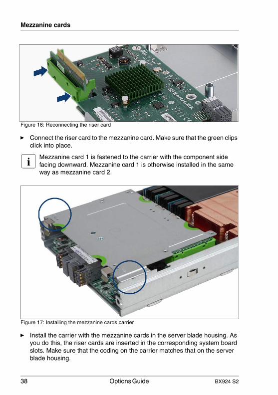
Figure 16: Reconnecting the riser card
Ê Connect the riser card to the mezzanine card. Make sure that the green clips click into place.
I Mezzanine card 1 is fastened to the carrier with the component side facing downward. Mezzanine card 1 is otherwise installed in the same way as mezzanine card 2.
Figure 17: Installing the mezzanine cards carrier
Ê Install the carrier with the mezzanine cards in the server blade housing. As you do this, the riser cards are inserted in the corresponding system board slots. Make sure that the coding on the carrier matches that on the server blade housing.

BX924 S2 Options Guide 39
Mezzanine cards
Ê Close the server blade, re-insert it in the system unit and switch it on as described in chapter "Completion" on page 49 and following.

40 Options Guide BX924 S2
Mezzanine cards
© c
ogni
tas.
Ges
ells
chft
für
Tech
nik-
Dok
ume
ntat
ion
mb
H 2
011
P
fad:
C:\P
rogr
am
me\
FC
T\ti
m_a
pp\ti
m_l
oca
l\wor
k\W
ALT
ER
\OB
J_D
OK
U-7
697-
002
.fm
BX924 S2 Options Guide 41
7 Trusted Platform Module (TPM)V CAUTION!
Please note the safety instructions in chapter "Safety instructions" on page 15.
7.1 Installing a TPM
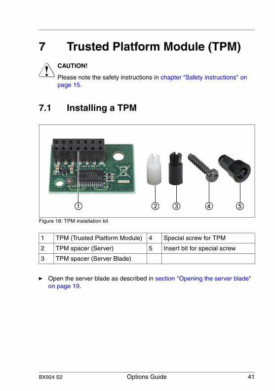
Figure 18: TPM installation kit
Ê Open the server blade as described in section "Opening the server blade" on page 19.
1 TPM (Trusted Platform Module) 4 Special screw for TPM
2 TPM spacer (Server) 5 Insert bit for special screw
3 TPM spacer (Server Blade)

42 Options Guide BX924 S2
Trusted Platform Module (TPM)
© c
ogni
tas.
Ges
ells
chft
für
Tech
nik-
Dok
ume
ntat
ion
mb
H 2
011
P
fad:
C:\P
rogr
am
me\
FC
T\ti
m_a
pp\ti
m_l
oca
l\wor
k\W
ALT
ER
\OB
J_D
OK
U-7
698-
002
.fm
Figure 19: TPM slot location
Figure 20: Installing the spacer
Ê Insert the spacer in the recess next to the multi-pin connector for the TPM. The plastic spacer must audibly click into place.

BX924 S2 Options Guide 43
Trusted Platform Module (TPM)
Figure 21: Connecting the TPM
Ê Connect the TPM to the multi-pin connector.
Ê Fasten the TPM using the special screw. Use a bit screwdriver and the special insert bit
I Do not fasten the screw too firmly. You must be able to remove it again.
Ê Close the server blade, re-insert it in the system unit and switch it on as described in chapter "Completion" on page 49 and following.
44 Options Guide BX924 S2
Trusted Platform Module (TPM)
© c
ogni
tas.
Ges
ells
chft
für
Tech
nik-
Dok
ume
ntat
ion
mb
H 2
011
P
fad:
C:\P
rogr
am
me\
FC
T\ti
m_a
pp\ti
m_l
oca
l\wor
k\W
ALT
ER
\OB
J_D
OK
U-7
698-
002
.fm

BX924 S2 Options Guide 45
8 USB Flash Module (UFM)V CAUTION!
Follow the safety instructions in the chapter "Safety instructions" on page 15.
8.1 Installing an UFM
Ê Open the server server blade as described in section "Opening the server blade" on page 19.
Figure 22: UFM kit
Ê Remove the plastic screw (1) and the plastic spacer (2). These parts are not needed for installation in the BX924 S2 server blade.
The slot for the UFM is located under the slot for mezzanine card 1.
Ê Remove the mezzanine cards carrier from the server blade housing by lifting it up, keeping it as horizontal as possible figure "Removing the mezzanine cards carrier" on page 36.

46 Options Guide BX924 S2
USB Flash Module (UFM)
© c
ogni
tas.
Ges
ells
chft
für
Tech
nik-
Dok
ume
ntat
ion
mb
H 2
011
P
fad:
C:\P
rogr
am
me\
FC
T\ti
m_a
pp\ti
m_l
oca
l\wor
k\W
ALT
ER
\OB
J_D
OK
U-7
699-
002
.fm
Figure 23: UFM slot location
Ê Connect the UFM to the multi-pin connector on the system board.
Figure 24: Fastening the UFM
Ê Fasten the UFM with a cross-head countersunk screw.

BX924 S2 Options Guide 47
USB Flash Module (UFM)
Ê Install the carrier with the mezzanine cards in the server blade housing. As you do this, the riser cards are inserted into the corresponding system board slots see figure "Inserting the mezzanine card" on page 37.
Ê Close the server blade, re-insert it in the system unit and switch it on as described in chapter "Completion" on page 49 and following.
48 Options Guide BX924 S2
USB Flash Module (UFM)
© c
ogni
tas.
Ges
ells
chft
für
Tech
nik-
Dok
ume
ntat
ion
mb
H 2
011
P
fad:
C:\P
rogr
am
me\
FC
T\ti
m_a
pp\ti
m_l
oca
l\wor
k\W
ALT
ER
\OB
J_D
OK
U-7
699-
002
.fm

BX924 S2 Options Guide 49
9 CompletionV CAUTION!
Follow the safety instructions in the chapter "Safety instructions" on page 15.
9.1 Closing the server blade
Figure 25: Closing the server blade
Ê Place the server blade cover on the housing about 1-2 cm from the frame so that it lies flush on both sides.
Ê Slide the cover forward in the direction of the arrow until it engages.
Ê Insert the server blade in the system unit.
I You insert the server blade in the opposite order to that described in "Removing the Server Blade from the system unit" on page 19.

50 Options Guide BX924 S2
Completion
© c
ogni
tas.
Ges
ells
chft
für
Tech
nik-
Dok
ume
ntat
ion
mb
H 2
011
P
fad:
C:\P
rogr
am
me\
FC
T\ti
m_a
pp\ti
m_l
oca
l\wor
k\W
ALT
ER
\OB
J_D
OK
U-7
700-
002
.fm

BX924 S2 Options Guide 51
IndexBbatteries 17
Cconnection blade 28
slots 29, 34
DDIMM modules
installing 25population 23replacing 25
documentationoverview 9
Eelectrostatic-sensitive devices
(ESD) 18
II/O modules
options 11information, additional 10installing
DIMM modules 25processor 11
Llithium battery 17
Mmain memory
expansion options 11modes of operation 24
meaning of the symbols 12mezzanine card 27
carrier 28form factor 27installing 36options 11population rules 28riser card 37
Nnotational conventions 12
Ooptions
I/O modules 11
Pprocessor
adding 11
RRDIMM (registered DIMM) 11, 23
Sserver blade
close 49opening 21removing from system unit 19
Ttarget group 9TPM 41
slot location 42special screw 41
Trusted Platform Module 41
UUDIMM (unbuffered DIMM) 11, 23UFM 45USB Flash Module 45

52 Options Guide BX924 S2
Index
© c
ogni
tas.
Ges
ells
chft
für
Tech
nik-
Dok
ume
ntat
ion
mb
H 2
011
P
fad:
C:\P
rogr
am
me\
FC
T\ti
m_a
pp\ti
m_l
oca
l\wor
k\W
ALT
ER
\OB
J_D
OK
U-7
701-
002
.fm


![PROCEEDINGS OF SPIE...9435 06 Design, modeling and test of a novel speed bump energy harvester [9435-5] 9435 07 Fluid flow nozzle energy harvesters [9435-6] 9435 08 Energy harvesting](https://static.fdocuments.in/doc/165x107/5f911f1969dd7343ae0def8f/proceedings-of-spie-9435-06-design-modeling-and-test-of-a-novel-speed-bump.jpg)