Optimux-134, Optimux-125 - Cutter Networks · Optimux-134, Optimux-125 Fiber Optic Multiplexer for...
8
Data Sheet Optimux-134, Optimux-125 Fiber Optic Multiplexer for 16-Channel TDM and Ethernet • Up to 16 E1/T1 links, full bandwidth 100 Mbps Ethernet traffic and high-speed data multiplexed into fiber optic uplink • 25/34 Mbps or 125/134 Mbps operation modes • Single-mode, multimode, single-mode over single fiber, SFP-based interfaces • Range of up to 110 km (68 miles) • Optional additional hot-swappable power supply and uplink for redundancy High-speed TDM and Ethernet services multiplexed over fiber Optimux-134 and Optimux-125 provide a simple, flexible, and cost-effective solution for transporting multiple E1/T1 links, high-speed data and Ethernet over an E3 copper or fiber link, to distances of up to 110 km (68 miles). The Access Company Each product features two license-activated operation modes: • In 25/34-Mbps operation mode, the units are fully compatible with Optimux-25/34 • In 125/134-Mbps mode, the products feature transport at 100 Mbps user Ethernet traffic. The fiber optic link is available with single-mode, multimode, and single-mode over single fiber interfaces. In 34-Mbps device operation mode, the Optimux-134 uplink is compliant with E3 standards for coax interfaces and works with 3 rd party devices. The Optimux-134/125 uplink with fiber interfaces is proprietary in both device operation modes.
Transcript of Optimux-134, Optimux-125 - Cutter Networks · Optimux-134, Optimux-125 Fiber Optic Multiplexer for...
Data Sheet
Optimux-134, Optimux-125Fiber Optic Multiplexer for 16-Channel TDM and Ethernet
• Up to 16 E1/T1 links, full bandwidth 100 Mbps Ethernet traffic and high-speed data multiplexed into fiber optic uplink
• 25/34 Mbps or 125/134 Mbps operation modes
• Single-mode, multimode, single-mode over single fiber, SFP-based interfaces
• Range of up to 110 km (68 miles)
• Optional additional hot-swappable power supply and uplink for redundancy
High-speed TDM and
Ethernet services
multiplexed over fiber Optimux-134 and Optimux-125 provide a simple, flexible, and cost-effective solution for transporting multiple E1/T1 links, high-speed data and Ethernet over an E3 copper or fiber link, to distances of up to 110 km (68 miles).
The Access Company
Each product features two license-activated operation modes:
• In 25/34-Mbps operation mode, the units are fully compatible with Optimux-25/34
• In 125/134-Mbps mode, the products feature transport at 100 Mbps user Ethernet traffic.
The fiber optic link is available with single-mode, multimode, and single-mode over single fiber interfaces.
In 34-Mbps device operation mode, the Optimux-134 uplink is compliant with E3 standards for coax interfaces and works with 3rd party devices. The Optimux-134/125 uplink with fiber interfaces is proprietary in both device operation modes.
Optimux-134, Optimux-125
Fiber Optic Multiplexer for 16-Channel TDM and Ethernet
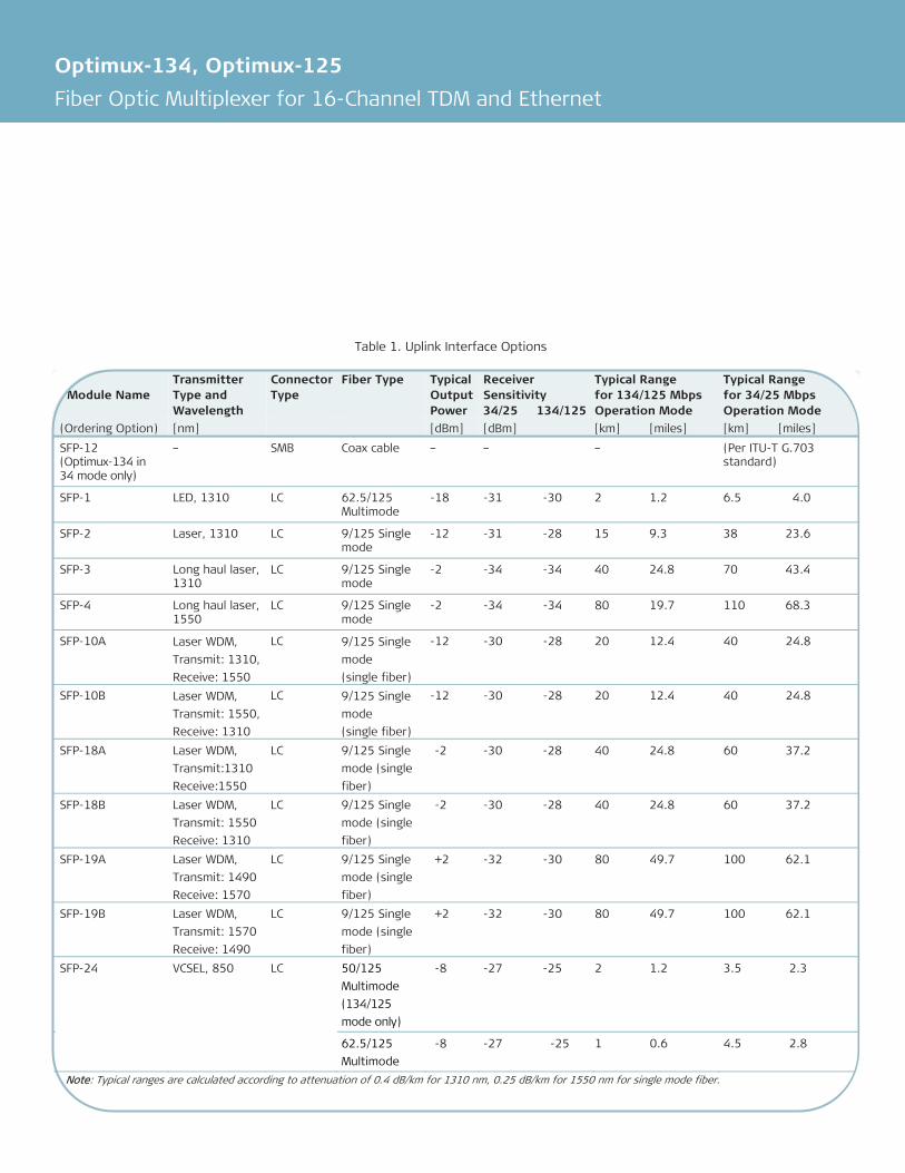
In 34/25-Mbps operation mode, the unit multiplexes up to 16 E1/T1 links. The data rate of the TDM ports can partially be replaced (user-selectable) by the 10/100BaseT user Ethernet traffic or by an optional high-speed data V.35 interface (see Table 1).
UPLINK INTERFACES
Various interfaces (based on SFP transceivers) are available for both the active and the backup uplinks (see Table 2 and Ordering Options):
• Electrical via coax (SMB) connector (34 Mbps mode operation only)
• 1310 nm short or long-haul laser and 1550 nm long-haul laser interfaces for extended range over single-mode fiber
• Single fiber interface using WDM technology, with the laser transmit signal at a different wavelength than the receive signal (1310 nm and 1550 nm).
LINK REDUNDANCY
Upon link failure, the unit automatically switches to an optional second uplink as a backup.
E1/T1 INTERFACE
Optimux-134, Optimux-125 multiplex 16 E1 or T1 channels. The E1/T1 interfaces comply with the ITU-T G.703. Line coding is HDB3 or B8ZS, respectively. A pair of LEDs monitors loss-of-signal and AIS on each E1/T1 receive line.
FAST ETHERNET INTERFACE
Optimux-134 and Optimux-125 feature fast Ethernet ports enabling a full 100-Mbps Ethernet connection in addition to the capacity of the 16 E1/T1 channels. The Optimux devices are supplied with a 10/100BaseT Ethernet USER port. This port is activated via a software key. The license can be purchased for 8/6-Mbps granularity to work in 34/25-Mbps operation mode, or for full bandwidth to work in 134/125-Mbps operation mode.
V.35 INTERFACE
The Optimux devices can be supplied with one V.35 (2048/1544 kbps) channel that replaces channel 16 by user activation. The V.35 interface can only be used in 34/25-Mbps operation mode.
TIMING
The Optimux devices transmit each E1/T1 channel separately so that the clock of each E1/T1 channel is independent. The devices support internal and loopback timing modes.
The 134/125-Mbps operation mode uses only Internal timing.
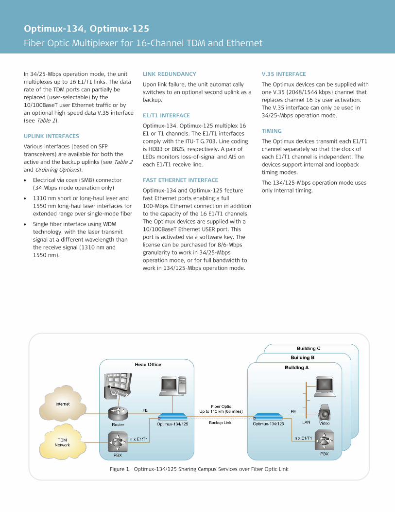
Figure 1. Optimux-134/125 Sharing Campus Services over Fiber Optic Link
Data Sheet
TYPICAL APPLICATIONS
Private Networks In private networks, Optimux-134/125 shares campus services such as Ethernet, Voice, Data and Video in P2P (Figure 1) and Star topologies over dark fiber.
Optimux establishes TDM and Ethernet connectivity between the remote branches and headquarters for educational, financial, military sectors.
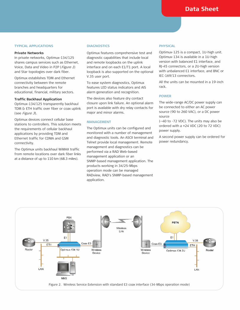
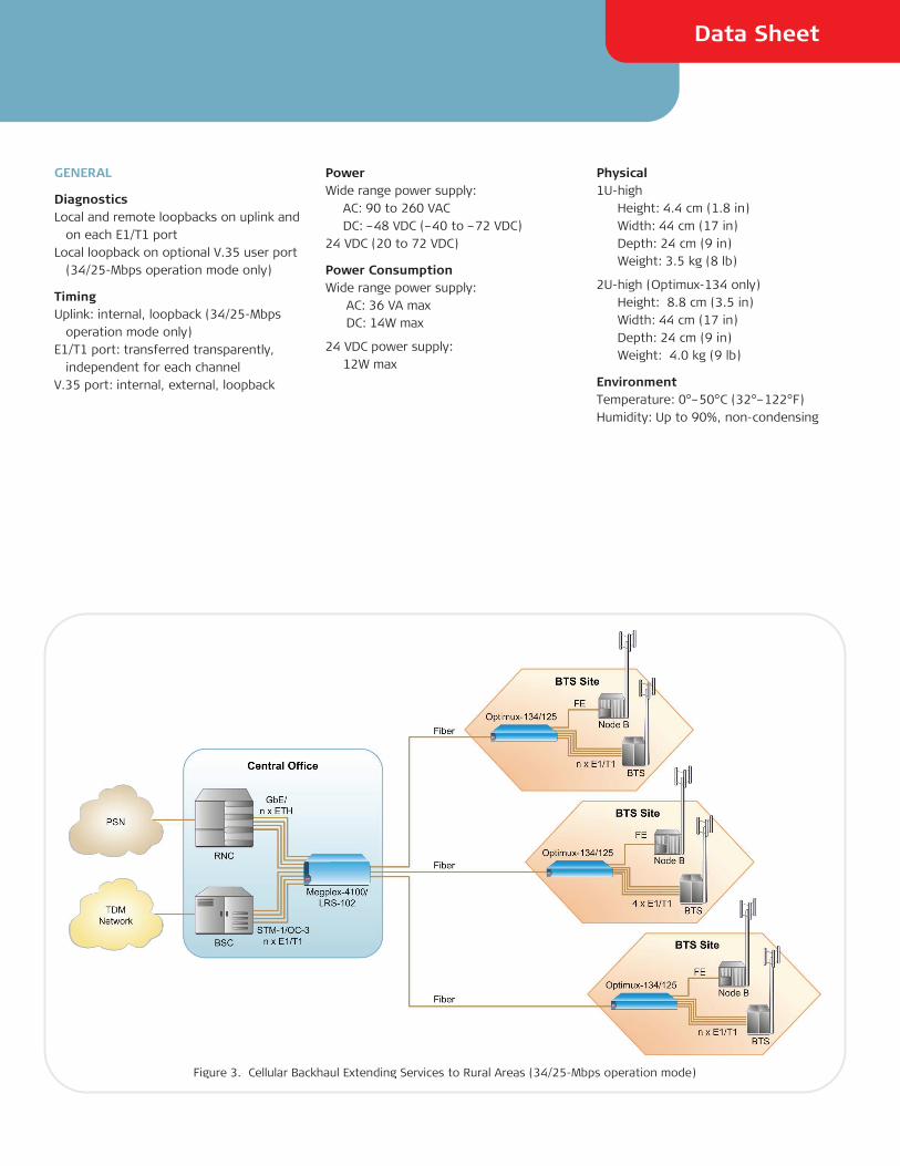
Traffic Backhaul Application Optimux-134/125 transparently backhaul TDM & ETH traffic over fiber or coax uplink (see Figure 3).
Optimux devices connect cellular base stations to controllers. This solution meets the requirements of cellular backhaul applications by providing TDM and Ethernet traffic for CDMA and GSM connectivity.
The Optimux units backhaul WiMAX traffic from remote locations over dark fiber links at a distance of up to 110 km (68.3 miles).
DIAGNOSTICS
Optimux features comprehensive test and diagnostic capabilities that include local and remote loopbacks on the uplink interface and on each E1/T1 port. A local loopback is also supported on the optional V.35 user port.
To ease system diagnostics, Optimux features LED status indicators and AIS alarm generation and recognition.
The devices also feature dry contact closure upon link failure. An optional alarm port is available with dry relay contacts for major and minor alarms.
MANAGEMENT
The Optimux units can be configured and monitored with a number of management and diagnostic tools. An ASCII terminal and Telnet provide local management. Remote management and diagnostics can be performed via a RAD Web-based management application or an SNMP-based management application. The products working in 34/25-Mbps operation mode can be managed RADview, RAD's SNMP-based management application.
PHYSICAL
Optimux-125 is a compact, 1U-high unit. Optimux-134 is available in a 1U-high version with balanced E1 interface, and RJ-45 connectors, or a 2U-high version with unbalanced E1 interface, and BNC or IEC-169/13 connectors.
All the units can be mounted in a 19-inch rack.
POWER
The wide-range AC/DC power supply can be connected to either an AC power source (90 to 260 VAC), or a DC power source (–40 to -72 VDC). The units may also be ordered with a +24 VDC (20 to 72 VDC) power supply.
A second power supply can be ordered for power redundancy.
Figure 2. Wireless Service Extension with standard E3 coax interface (34-Mbps operation mode)
Optimux-134, Optimux-125
Fiber Optic Multiplexer for 16-Channel TDM and Ethernet
Specifications
LINK INTERFACES (MAIN AND BACKUP)
Data Rate OP-134:
• 134-Mbps mode: 135.168 Mbps (RAD proprietary)
• 34-Mbps mode: E3-34.368 Mbps
OP-125 (RAD proprietary):
• 125-Mbps mode: 127.38 Mbps
• 25-Mbps mode: 25.910 Mbps
Interface Options See Table 1
Note: It is strongly recommended to order this
device with original RAD SFPs installed. This will
ensure that prior to shipping, RAD has performed
comprehensive functional quality tests on the
entire assembled unit, including the SFP devices.
RAD cannot guarantee full compliance to product
specifications for units using non-RAD SFPs.
Connectors SFP interfaces with LC connectors
Standards OP-134: ITU G.703, G.742, G.751, G.823, G.955, IEEE 802.3
OP-125: ITU G.703, G.824, G.955, IEEE 802.3
FAST ETHERNET INTERFACES
Activated via a software key for 8/6 Mbps granularity or full bandwidth.
Type 10/100BaseT
Connectors RJ-45
E1/T1 INTERFACE
Number of Channels 16
Data Rate E1: 2048 kbps T1: 1544 kbps
Impedance E1 balanced: 120Ω E1 unbalanced: 75Ω T1 balanced: 100Ω
Connectors E1 balanced: RJ-45 E1 unbalanced: BNC or IEC-169/13 (in 2U unit)
Note: For balanced and unbalanced channels in the
same unit, order a 1U-high unit and one
CBL-RJ45/BNC/E1/X adaptor cable for each pair of
BNC connectors.
T1 balanced: RJ-45
HIGH-SPEED INTERFACE
Type V.35
Connector DB-25 (ISO-2110 or Telebras pinout)
CONTROL PORT
Type RS-232 DCE asynchronous
Data Rate 9.6, 19.2, 38.4, 57.6, 115.2 kbps
Connector 9-pin D-type female
ALARM PORT
Type Dry relay contacts for major and minor alarms
Connector 9-pin D-type female
INDICATORS
Power Off – Not powered On (green) – Normal operation On (red) – Power malfunction
System TST (yellow) – On: Diagnostic loop is performed or during power up
TST (yellow) – Flashes: During auto baud detect process
FLT (red) – During power up
Link SFP (per port) SYNC LOSS (red) – Signal loss or frame loss detected on uplink AIS (yellow) – AIS detected on uplink (relevant only in 34/25-Mbps operation mode)
User Ethernet Port LINK/ACT (yellow) – On: LAN status is up LINK/ACT (yellow) – Flashes: LAN traffic transfer 100 (green) – On: 100-Mbps operation 100 (green) – Off: 10-Mbps operation
E1/T1 Interface (per port) SYNC LOSS (red) – Signal loss detected on E1/T1 link AIS (yellow) – AIS detected on E1/T1 link
Management Port LINK/ACT (lights yellow) – LAN up status LINK/ACT (flashes yellow) – LAN traffic transfer 100 (green) – On: 100 Mbps operation 100 (green) – Off: 10 Mbps operation
Data Sheet
GENERAL
Diagnostics Local and remote loopbacks on uplink and
on each E1/T1 port Local loopback on optional V.35 user port
(34/25-Mbps operation mode only)
Timing Uplink: internal, loopback (34/25-Mbps
operation mode only) E1/T1 port: transferred transparently,
independent for each channel V.35 port: internal, external, loopback
Power Wide range power supply: AC: 90 to 260 VAC DC: –48 VDC (–40 to –72 VDC) 24 VDC (20 to 72 VDC)
Power Consumption Wide range power supply: AC: 36 VA max DC: 14W max
24 VDC power supply: 12W max
Physical 1U-high
Height: 4.4 cm (1.8 in) Width: 44 cm (17 in) Depth: 24 cm (9 in) Weight: 3.5 kg (8 lb)
2U-high (Optimux-134 only) Height: 8.8 cm (3.5 in) Width: 44 cm (17 in) Depth: 24 cm (9 in) Weight: 4.0 kg (9 lb)
Environment Temperature: 0°–50°C (32°–122°F) Humidity: Up to 90%, non-condensing
Figure 3. Cellular Backhaul Extending Services to Rural Areas (34/25-Mbps operation mode)
Optimux-134, Optimux-125
Fiber Optic Multiplexer for 16-Channel TDM and Ethernet
Module Name
Transmitter Type and Wavelength
Connector Type
Fiber Type Typical Output Power
Receiver Sensitivity 34/25 134/125
Typical Range for 134/125 Mbps Operation Mode
Typical Range for 34/25 Mbps Operation Mode
(Ordering Option) [nm] [dBm] [dBm] [km] [miles] [km] [miles]
SFP-12 (Optimux-134 in 34 mode only)
– SMB Coax cable – – – (Per ITU-T G.703 standard)
SFP-1 LED, 1310 LC 62.5/125 Multimode
-18 -31 -30 2 1.2 6.5 4.0
SFP-2 Laser, 1310 LC 9/125 Single mode
-12 -31 -28 15 9.3 38 23.6
SFP-3 Long haul laser, 1310
LC 9/125 Single mode
-2 -34 -34 40 24.8 70 43.4
SFP-4 Long haul laser, 1550
LC 9/125 Single mode
-2 -34 -34 80 19.7 110 68.3
SFP-10A Laser WDM,
Transmit: 1310,
Receive: 1550
LC 9/125 Single
mode
(single fiber)
-12 -30 -28 20 12.4 40 24.8
SFP-10B Laser WDM,
Transmit: 1550,
Receive: 1310
LC 9/125 Single
mode
(single fiber)
-12 -30 -28 20 12.4 40 24.8
SFP-18A Laser WDM,
Transmit:1310
Receive:1550
LC 9/125 Single
mode (single
fiber)
-2 -30 -28 40 24.8 60 37.2
SFP-18B
Laser WDM,
Transmit: 1550
Receive: 1310
LC 9/125 Single
mode (single
fiber)
-2 -30 -28 40 24.8 60 37.2
SFP-19A Laser WDM,
Transmit: 1490
Receive: 1570
LC 9/125 Single
mode (single
fiber)
+2 -32 -30 80 49.7 100 62.1
SFP-19B Laser WDM,
Transmit: 1570
Receive: 1490
LC 9/125 Single
mode (single
fiber)
+2 -32 -30 80 49.7 100 62.1
SFP-24 VCSEL, 850 LC 50/125
Multimode
(134/125
mode only)
-8 -27 -25 2 1.2 3.5 2.3
62.5/125
Multimode
-8 -27 -25 1 0.6 4.5 2.8
Note: Typical ranges are calculated according to attenuation of 0.4 dB/km for 1310 nm, 0.25 dB/km for 1550 nm for single mode fiber.
Table 1. Uplink Interface Options
Data Sheet
Ordering
OP-134/*/?/+/%/! 16-Channel E1 and Ethernet-over-E3/Fiber-Optic Multiplexer
OP-125/*/+/%/! 16-Channel T1 and Ethernet-over-Fiber-Optic Multiplexer
Legend
* Power supply (Default=one OP-125-134-PS wide range power supply):
PSR Dual wide range power supply (90-260 AC, -40— -70 VDC)
DC Single +24/-48 VDC DCR Dual +24/-48 VDC
? E1 connector for Optimux-134: B Balanced (RJ-45, 1U-high unit) U Unbalanced (BNC, 2U-high unit) UBR Unbalanced (IEC-169/13,
2U-high unit with DIP switches to disconnect GND from the Rx signal)
+ Alarm port (Default=no alarm port): A Alarm port
% V.35 user port (Default=no V.35 user port):
V35 DB-25 connector with ISO-2110 pinout
V35T DB-25 connector with Telebras pinout
! Activation key (Default=no activation key, the device will function with 16 E1/T1 ports only):
6M Software key for activating the 10/100BaseT Ethernet port at 6 Mbps granularity (Optimux-125 only)
8M Software key for activating the 10/100BaseT Ethernet port at 8 Mbps granularity (Optimux-134 only)
100M Software key for activating the 10/100BaseT Ethernet USER port at 100 Mbps and 134/125 Mbps operation mode
Uplink Interface (SFP) Table 1 specifies the uplink interface options. To order uplink interface from RAD, refer to the SFP Transceivers Data Sheet at www.rad.com.
It is strongly recommended to order this device with original RAD SFPs installed. This will ensure that prior to shipping, RAD has performed comprehensive functional quality tests on the entire assembled unit, including the SFP devices.
Notes: 1. When ordering redundant SFPs, they
must be identical.
2. Single-fiber SFPs should always be used opposite
the reciprocal single fiber SFP. For example,
SFPs-10A should be used opposite SFP-10B.
3. RAD cannot guarantee full compliance to product
specifications for units using non-RAD SFPs.
4. Optimux-134, Optimux-125 are supplied with
two SFP sockets, the transceivers must be ordered
separately.
SUPPLIED ACCESSORIES
AC/DC power cord
RM-34 Kit for mounting one 1U-high unit in a 19-inch rack (for balanced unit only)
RM-36 Kit for mounting one 2U-high Optimux-134 unit in a 19-inch rack (for unbalanced unit only)
OPTIONAL ACCESSORIES
OP-134-LIC-ETH/! OP-125-LIC-ETH/! Software keys for activating the 10/100BaseT Ethernet port
Legend
! Capacity: 6M License activation key for
Ethernet at 6 Mbps granularity (for Optimux-125)
8M License activation key for Ethernet at 8 Mbps granularity (for Optimux-134)
100M License activation key for full Ethernet capacity and 134/125-Mbps operation mode
329-1
00-0
8/1
0 (3
.0) Sp
ecifications are su
bject to
chan
ge with
out p
rior n
otice. ©
1997–2010 R
AD
Data Co
mm
unicatio
ns Ltd
. The R
AD
nam
e, logo
, logo
type, an
d th
e terms Eth
erAccess, TD
MoIP an
d TD
MoIP D
riven,
RA
D D
ata Com
municatio
ns Ltd
. All o
ther trad
emarks are th
e pro
perty o
f their re
spective h
old
ers. an
d th
e pro
duct n
ames O
ptim
ux an
d IPm
ux, are registered
tradem
arks of
Optimux-134, Optimux-125
Fiber Optic Multiplexer for 16-Channel TDM and Ethernet
Data Sheet
OP-125-134-PS Wide range 90–260 VAC/–48 VDC power supply modules for adding a redundant power supply to an existing unit or replacing the original power supply module
OP-125-134-PS-BP Blank panels for power supply modules
CBL-RJ45/BNC/E1/X RJ-45 to BNC adapter cross-cable (for use with 1U Optimux-134 chassis)
CBL-8H/M/1METER V.35, DB-25 to M-34 cable for Optimux-134 and Optimux-125
CBL-DB9F-DB9M-STR Control port cable
CBL-SMB-BNC/M SMB to BNC adapter cable for Optimux-134 (supplied with SFP-12)
Table 2. Optimux Comparison Table
International Headquarters 24 Raoul Wallenberg Street Tel Aviv 69719, Israel Tel. 972-3-6458181 Fax 972-3-6498250, 6474436 E-mail [email protected]
North America Headquarters 900 Corporate Drive Mahwah, NJ 07430, USA Tel. 201-5291100 Toll free 1-800-4447234 Fax 201-5295777 E-mail [email protected]
www.rad.com Order this publication by Catalog No. 803917
The Access Company
Feature Optimux-108L
Optimux-108/106
Optimux-34/25
Optimux-134/125
Optimux-45/45L Optimux-1551 Optimux-1553
Uplink Fiber Optic Fiber Optic E3, Fiber Optic E3, Fiber Optic T3, Fiber Optic Copper,
STM-1/OC-3
Copper,
STM-1/OC-3
Bandwidth
(Mbps)
108 108/81 34/25 34/25 or 134/125 45 155 155
Number of
trunks
4 E1 4 E1/4 T1 16 E1/16T1
16 E1/16T1 21 E1/28 T1 21/42/63 E1
28/56/84 T1
3 E3/3 T3
Ethernet
support
– – –
Special
features
Reduced Power
Consumption
Cost-Effective
Redundant,
hot-swappable
uplinks
SFP-based uplinks Full Bandwidth Ring support
(Optimux-45)
Full redundancy Full redundancy
Card
version for
LRS-102/
MP-4100
Supports
OP-34/25C
– – –


![Journal of Drug Delivery and Therapeutics€¦ · Reddy et al Journal of Drug Delivery & Therapeutics. 2018; 8(6-s):125-134 ISSN: 2250-1177 [125] CODEN (USA): JDDTAO ... spectrofluorometry,](https://static.fdocuments.in/doc/165x107/6063212f626f4618e661cad3/journal-of-drug-delivery-and-therapeutics-reddy-et-al-journal-of-drug-delivery-.jpg)