Optimum receiver performance of TH-PPM ultra wideband ...
8
Paper Optimum receiver performance of TH-PPM ultra wideband system in multiple user interference Mohammad Upal Mahfuz, Kazi M. Ahmed, and Nandana Rajatheva Abstract—This paper demonstrates optimum receiver per- formance in terms of bit error rate (BER) for time hop- ping pulse position modulation (TH-PPM) ultra wideband (UWB) system in multiple user interference environment for indoor radio communication. Equal gain combining and se- lective gain combining have been demonstrated in terms of ideal RAKE (ARAKE), selective RAKE (SRAKE) and par- tial RAKE (PRAKE) receiver performances. The recently accepted IEEE 802.15.3a model of the UWB channel has been used to describe UWB propagation in indoor environ- ment. Two channel scenarios named CM-1 and CM-3 for IEEE 802.15.3a channel model have been investigated prin- cipally. Finally, this paper concludes with an approxima- tion of equivalence of number of fingers in SRAKE and PRAKE receivers as well as an indication of SNR gains achievable as the RAKE finger number is increased, espe- cially with multiple user interference (MUI), for a 16.6 Mbit/s UWB system. Keywords— optimum receiver performance, TH-PPM, ultra wideband, multiple user interference. 1. Introduction Ultra wideband impulse radio (UWB-IR) is currently re- ceiving a great deal of global attention because of its abil- ity to provide higher data rate with low cost and relatively low power consumption. Impulse radio UWB communi- cates with baseband pulses of very short duration on the order of tenth of a nanosecond. According to the regulation of Federal Commission of Communications (FCC), a sig- nal is defined as UWB signal if it has a –10 dB fractional bandwidth, F BW greater than (or equal to) 0.20 or it occu- pies at least 500 MHz of the spectrum [1], the fractional bandwidth being expressed as F BW = 2 f H − f L f H + f L ≥ 0.20 , (1) where f H and f L correspond to the –10 dB upper and lower frequencies, respectively. The FCC has also reg- ulated the spectral shape and maximum power spectral density (–41.3 dBm/MHz) of the UWB radiation in order to limit the interference with other communication sys- tems like UMTS or WLAN [2]. The waveforms that are used for UWB radio are very short in duration, causing their energy to be spread across the frequency spectrum. With UWB signals the dense multipath can be resolved, al- lowing a RAKE receiver for signal demodulation. Multiple access in UWB communications is accomplished with tra- ditional spread-spectrum techniques. Most of the research conducted so far is concerned with time hopping (TH) spread spectrum, associated with either binary pulse posi- tion modulation (TH-PPM) [3] or bipolar pulse amplitude modulation (TH-PAM) [4]. The performance of RAKE re- ceivers operating with TH-PPM has been investigated in [5] in the absence of multiple user interference (MUI) and as- suming perfect channel knowledge. The impact of MUI on the detection process is discussed in [3] with line-of- sight (LOS) propagation. Unfortunately, in the presence of MUI the question of optimum performance is so com- plex that physical intuition does not help and an analyt- ical approach seems impossible [4]. Clearly, MUI plays a role both in channel estimation as well as in receiver performance. In this paper we extend these results in various ways. We have compared the performances ideal, selective and partial RAKE receiver performances for TH-PPM UWB scheme in presence of low to moderate multiple user interference using two channel models named CM-1 and CM-2 as de- scribed recently by the IEEE 802.15.3a [6] standardiza- tion group for use in indoor UWB communications [7]. We have also shown how the system performance changes as the number of RAKE fingers varies. In particular, our re- search targets optimum receiver performance and compari- son of the system performances between CM-1 and CM-3, which are 0–2 m LOS and 4–10 m NLOS channel con- ditions and are used very often in UWB system perfor- mance evaluation studies. Finally, since indoor radio com- munication is affected by a large number of multipaths, the equivalence between selective RAKE (SRAKE) and partial RAKE (PRAKE) finger numbers is another important as- pect that this paper has addressed regarding TH-PPM UWB scheme. The paper is organized as follows: Section 2 pro- vides with a brief description of the concept of multiuser interference. The discussion is followed by Section 3 de- scribing the complete system model under investigation as well as detailed simulation environment. Section 4 briefly describes RAKE receiver principle regarding SRAKE and PRAKE operations, which is then followed by Section 5 discussing the results obtained with extensive simulation of the TH-PPM UWB system. Finally, Section 6 concludes the paper. 77
Transcript of Optimum receiver performance of TH-PPM ultra wideband ...

Paper
Optimum receiver performance
of TH-PPM ultra wideband system
in multiple user interference
Mohammad Upal Mahfuz, Kazi M. Ahmed, and Nandana Rajatheva
Abstract—This paper demonstrates optimum receiver per-
formance in terms of bit error rate (BER) for time hop-
ping pulse position modulation (TH-PPM) ultra wideband
(UWB) system in multiple user interference environment for
indoor radio communication. Equal gain combining and se-
lective gain combining have been demonstrated in terms of
ideal RAKE (ARAKE), selective RAKE (SRAKE) and par-
tial RAKE (PRAKE) receiver performances. The recently
accepted IEEE 802.15.3a model of the UWB channel has
been used to describe UWB propagation in indoor environ-
ment. Two channel scenarios named CM-1 and CM-3 for
IEEE 802.15.3a channel model have been investigated prin-
cipally. Finally, this paper concludes with an approxima-
tion of equivalence of number of fingers in SRAKE and
PRAKE receivers as well as an indication of SNR gains
achievable as the RAKE finger number is increased, espe-
cially with multiple user interference (MUI), for a 16.6 Mbit/s
UWB system.
Keywords— optimum receiver performance, TH-PPM, ultra
wideband, multiple user interference.
1. Introduction
Ultra wideband impulse radio (UWB-IR) is currently re-
ceiving a great deal of global attention because of its abil-
ity to provide higher data rate with low cost and relatively
low power consumption. Impulse radio UWB communi-
cates with baseband pulses of very short duration on the
order of tenth of a nanosecond. According to the regulation
of Federal Commission of Communications (FCC), a sig-
nal is defined as UWB signal if it has a –10 dB fractional
bandwidth, FBW greater than (or equal to) 0.20 or it occu-
pies at least 500 MHz of the spectrum [1], the fractional
bandwidth being expressed as
FBW = 2fH − fL
fH + fL
≥ 0.20 , (1)
where fH and fL correspond to the –10 dB upper and
lower frequencies, respectively. The FCC has also reg-
ulated the spectral shape and maximum power spectral
density (–41.3 dBm/MHz) of the UWB radiation in order
to limit the interference with other communication sys-
tems like UMTS or WLAN [2]. The waveforms that are
used for UWB radio are very short in duration, causing
their energy to be spread across the frequency spectrum.
With UWB signals the dense multipath can be resolved, al-
lowing a RAKE receiver for signal demodulation. Multiple
access in UWB communications is accomplished with tra-
ditional spread-spectrum techniques. Most of the research
conducted so far is concerned with time hopping (TH)
spread spectrum, associated with either binary pulse posi-
tion modulation (TH-PPM) [3] or bipolar pulse amplitude
modulation (TH-PAM) [4]. The performance of RAKE re-
ceivers operating with TH-PPM has been investigated in [5]
in the absence of multiple user interference (MUI) and as-
suming perfect channel knowledge. The impact of MUI
on the detection process is discussed in [3] with line-of-
sight (LOS) propagation. Unfortunately, in the presence
of MUI the question of optimum performance is so com-
plex that physical intuition does not help and an analyt-
ical approach seems impossible [4]. Clearly, MUI plays
a role both in channel estimation as well as in receiver
performance.
In this paper we extend these results in various ways. We
have compared the performances ideal, selective and partial
RAKE receiver performances for TH-PPM UWB scheme
in presence of low to moderate multiple user interference
using two channel models named CM-1 and CM-2 as de-
scribed recently by the IEEE 802.15.3a [6] standardiza-
tion group for use in indoor UWB communications [7]. We
have also shown how the system performance changes as
the number of RAKE fingers varies. In particular, our re-
search targets optimum receiver performance and compari-
son of the system performances between CM-1 and CM-3,
which are 0–2 m LOS and 4–10 m NLOS channel con-
ditions and are used very often in UWB system perfor-
mance evaluation studies. Finally, since indoor radio com-
munication is affected by a large number of multipaths, the
equivalence between selective RAKE (SRAKE) and partial
RAKE (PRAKE) finger numbers is another important as-
pect that this paper has addressed regarding TH-PPM UWB
scheme. The paper is organized as follows: Section 2 pro-
vides with a brief description of the concept of multiuser
interference. The discussion is followed by Section 3 de-
scribing the complete system model under investigation as
well as detailed simulation environment. Section 4 briefly
describes RAKE receiver principle regarding SRAKE and
PRAKE operations, which is then followed by Section 5
discussing the results obtained with extensive simulation
of the TH-PPM UWB system. Finally, Section 6 concludes
the paper.
77
Mohammad Upal Mahfuz, Kazi M. Ahmed, and Nandana Rajatheva
2. Concept of multiuser interference
Multiple user interference is modeled as signals coming
from other UWB users having the same basic signal char-
acteristics as those of the user of interest, but using different
spreading codes. Assuming a total of Nu users, the received
signal r(t) can be written as
r(t) = s(1)(t)⊗h(1)(t)+ i(t)+ n(t) , (2)
where s(1)(t) is the signal of interest at the output of
the transmitting antenna, h(1)(t) represents the impulse re-
sponse of the channel corresponding to the user of interest,
n(t) is the Gaussian noise and i(t) is the interference com-
ing from the other (Nu − 1) users. Here the interference,
i(t) can be defined as
i(t) =Nu
∑n=2
s(n)(t − τn)⊗h(n)(t) , (3)
where h(n)(t) for n = 2, 3 . . . ,Nu are the impulse responses
of the channels corresponding to the (Nu − 1) interfering
users and τn is the delay of the arrival time of the nth user
from the user of interest, i.e., s(1)(t) for which τ1 = 0.
Each user experiences the channel with a different channel
realization so that the channel impulse response
h(n)(t) 6= h(m)(t) ,
where n, m = 1, 2, . . . Nu, n 6= m.
Each MUI user has the same power as the user of inter-
est. Interfering users are considered either synchronous or
asynchronous with the user of interest. The “synchronous”
condition refers to “frame synchronization” where the re-
ceiver is synchronized with all other users and can receive
all users’ data at the same time instant. On the other hand,
in the asynchronous case, the interfering signals arrive at
the receiver with resolution of a time sample. The asyn-
chronism is performed between every interfering user and
the user of interest, and also among the interfering users.
3. System model
In this paper, TH-PPM transmission has been used in the
transmitter section. Time hopping is a widely used mul-
tiple access method for UWB radio communications. The
most recent IEEE 802.15.3a UWB channel model has been
chosen as the channel used for UWB propagation. Details
of simulation parameters have been shown in Table 1.
3.1. The UWB pulse shape and modulation schemes
A typical energy normalized UWB TH-PPM signal can be
modeled as follows:
s(k)tr
(
t(k))
=∞
∑j=−∞
wtr
(
t(k) − jTf − c(k)j Tc −d
(k)j ∆
)
, (4)
where c j is the distinct time hopping sequence, t is the
transmitter clock time, wtr is the transmitted monocycle
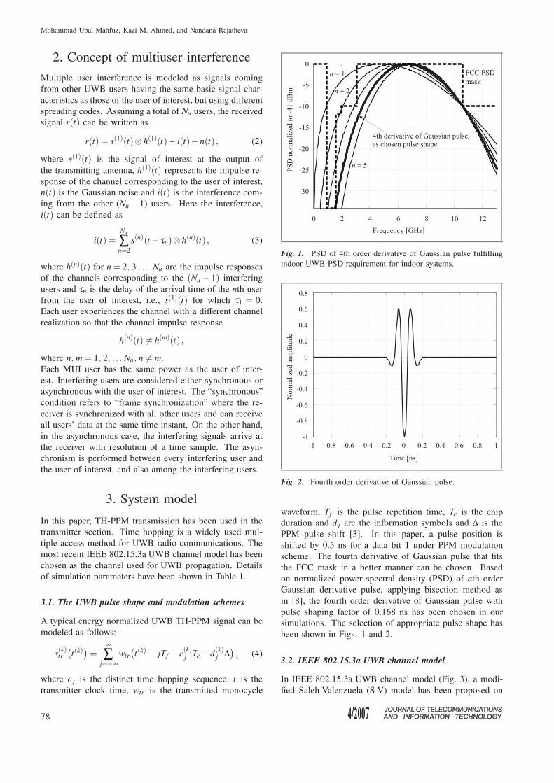
Fig. 1. PSD of 4th order derivative of Gaussian pulse fulfilling
indoor UWB PSD requirement for indoor systems.
Fig. 2. Fourth order derivative of Gaussian pulse.
waveform, Tf is the pulse repetition time, Tc is the chip
duration and d j are the information symbols and ∆ is the
PPM pulse shift [3]. In this paper, a pulse position is
shifted by 0.5 ns for a data bit 1 under PPM modulation
scheme. The fourth derivative of Gaussian pulse that fits
the FCC mask in a better manner can be chosen. Based
on normalized power spectral density (PSD) of nth order
Gaussian derivative pulse, applying bisection method as
in [8], the fourth order derivative of Gaussian pulse with
pulse shaping factor of 0.168 ns has been chosen in our
simulations. The selection of appropriate pulse shape has
been shown in Figs. 1 and 2.
3.2. IEEE 802.15.3a UWB channel model
In IEEE 802.15.3a UWB channel model (Fig. 3), a modi-
fied Saleh-Valenzuela (S-V) model has been proposed on
78

Optimum receiver performance of TH-PPM ultra wideband system in multiple user interference
Fig. 3. The system model.
Table 1
Parameters used in simulation of the complete system
Parameters Values used in simulation
Source data rate [Mbit/s] 16.6
Processing gain [dB] 20.79
Average transmitter -30power [dBm]
Sampling frequency [GHz] 30
No. of pulse per bit 1
Frame time [ns] 60.1
Periodicity of the TH code 2000
Chip time [ns] 1
Multiuser interference Single user and multiple userscenarios
Receiver ARAKE SRAKE, PRAKE with2, 4, 6, 8, 10, 12, 14, 16, 18,20, 32 fingers
Channel model IEEE 802.15.3a,CM-1: 0–2 m, LOS andCM-3: 4–10 m, NLOS
Modulation scheme PPM
Multiple access TH
Time shift for PPM [ns] 0.5
Pulse shape Gaussian 4th derivative
Pulse width [ns] 0.5
Pulse decay factor [ns] 0.168
Code cardinality 5
the basis of observed clustering phenomenon in several
channel measurements [7]. Lognormal distribution rather
than Rayleigh distribution for the multipath gain magnitude
has been recommended. In addition, independent fading is
assumed for each cluster as well as each ray within the
cluster. Therefore, the discrete impulse response of the
multipath channel model (Fig. 4) can be described as [6]
hi(t) = Xi
L
∑l=0
K
∑k=0
α ik,lδ (t −T i
l − τ ik,l) , (5)
where {α ik,l} are the multipath gain coefficients, {T i
l } is
the delay of the lth cluster, {τ ik,l} is the delay of the
kth multipath component relative to the lth cluster arrival
time (T il ), {Xi} represents the lognormal shadowing and
i refers to the ith realization. So, according to the model,
Tl represents the arrival time of the first path (ray) of
the lth cluster; τk,l is the delay of the kth path (ray) within
the lth cluster relative to the first path arrival time, Tl .
Fig. 4. Discrete time channel impulse response for: (a) CM-1:
0–2 m (LOS); (b) CM-3: 4–10 m (NLOS).
The IEEE 802.15.3a channel model has been explained
for four special cases depending on transmitter to receiver
distance and the availability of line of sight path be-
Table 2
Model parameters in IEEE 802.15.3a UWB channel [7]
CM-1 CM-3Model parameters LOS at NLOS at
0–2 m 4–10 m
Cluster arrival rate, Λ [1/ns] 0.0233 0.0667
Ray arrival rate, λ [1/ns] 2.5 2.1
Cluster decay factor, Γ 7.1 14
Ray decay factor, γ 4.3 7.9
Std. dev. of cluster log-normal 3.3941 3.3941fading, σ1 [dB]
Std. dev. of ray log-normal 3.3941 3.3941fading, σ2 [dB]
Std. dev. of total multipath 3 3log-normal fading, σx [dB]
79

Mohammad Upal Mahfuz, Kazi M. Ahmed, and Nandana Rajatheva
tween them. In this study, CM-1 (0–2 m, LOS) and CM-3
(4–10 m, NLOS) condition of the channel have been used
and the corresponding channel parameters are shown in
Table 2.
3.3. Receiver section
In the receiver section, selective RAKE receiver has been
used. The received signal is the sum of replicas of the
transmitted signals. The received signal is, therefore, ex-
pressed as
r(t) = XL
∑l=1
K
∑k=1
αk,lstr(t −Tl − τk,l)+ n(t)+ i(t) , (6)
where str(t) is the transmitted signal which suffers from
attenuation and time delay in multipath propagation, n(t)is zero mean additive white Gaussian noise (AWGN) and
i(t) is the multiple user interference signal. For simulation
of this study RAKE receivers with 2, 4, 6, 8, 10, 12, 14,
16, 18, 20 and 32 fingers have been used and finding an
optimum RAKE receiver finger number has been targeted.
First arm is locked to the first multipath component, m1.
Multipath component, m2 arrives τ1 time units later than
m1 and is captured and so on. All decision statistics are
weighted by a weighting factor, α to form overall decision
statistics. The signals are then integrated over the entire
period. The integrated signal is then compared with the
appropriate threshold value to receive the better estimate
of the transmitted signal. Since one pulse per bit of infor-
mation transmitted is used all through, any of hard decision
detection (HDD) or soft decision detection (SDD) can be
used at the receiver, however, HDD has been adopted in
this paper with TH-PPM UWB systems.
4. RAKE receiver principles
The goal of a RAKE receiver is to combine the energies of
the useful signal components. Unfortunately, as a typical
UWB channel has hundreds of resolvable paths, too many
fingers would be necessary to capture all these energies. In
practice, power consumption and channel estimation issues
limit the number of fingers to ten or so. This prompts
the notion of SRAKE [5], in which only the strongest
paths are exploited. On the other hand, an ideal RAKE
(ARAKE) is an ideal receiver in which all the non-zero
resolvable multipaths are combined. Its performance estab-
lishes a benchmark for comparison of practical receivers.
The operating principle of an SRAKE is as follows. Let
{αq}Qq=1
be the gains of Q strongest paths and {τq}Qq=1
the corresponding delays. Also let us assume that the re-
ceiver achieved perfect symbol synchronization for the de-
sired signal. Then according to [4] the decision statistic for
the symbol ai is a weighted sum of the type (maximum
ratio combining):
xi =Q
∑q=1
αq
(i+1)N f Tf∫
iN f Tf
r(t)v(t − iN f Tf − τq)dt , (7)
where {αq} and {τq} are the gain and delay estimates
and v(t) is a correlation template waveform depending on
the signaling format, which for TH-PPM case, can be ex-
pressed as
v(t) = wtr(t)−wtr(t −∆) . (8)
With TH-PPM a decision a = 0 or ai = 1 is made accord-
ing to whether xi is positive or negative, respectively, the
corresponding decision being ai = 1 or ai = −1.
The channel impulse response (CIR) is assumed to be
known. The total number of non-zero multipath compo-
nents is found. In the case of ARAKE, all of the non-
zero multipath components of CIR vector are considered
with equal weight for the weighting factor vector, whereas
for SRAKE a predefined number of weighting coefficients
are considered in the descending order of their magnitude
and the weighting factor vector is formed giving weight
proportional to the magnitude of the respective multipath
component. On the other hand, in the case of PRAKE re-
ceivers, a predefined number of multipath components are
considered according to their propagation delay, i.e., on first
receive first take basis and not on the basis of descending
order of the magnitude as in SRAKE.
5. Results
The bit error rate (BER) performance of UWB system
varies significantly as the number of fingers of RAKE re-
ceiver in use varies, as shown in this paper in case of TH-
PPM UWB system using IEEE 802.15.3a UWB channel
Table 3
Equivalence of PRAKE fingers at BER = 10−1
No. of multi- CM-3 CM-1
users SRAKE Eqv. PRAKE SRAKE Eqv. PRAKE
0, i.e., single user 2 8 2 4
4 12 4 10
8 20 8 14
16 32 16 16
5 2 8 2 6
4 12 4 8
8 20 8 14
16 –32 16 20
10 2 8 2 6
4 12 4 8
8 18 8 14
16 32 16 20
20 2 8 2 6
4 14 4 10
8 20 8 14
16 32 16 20
80

Optimum receiver performance of TH-PPM ultra wideband system in multiple user interference
Fig. 5. Performance of TH-PPM UWB system under different multiple user scenarios: (a) single user; (b) 5; (c) 10; (d) 20; (e) 40 in-
terfering users; (f) required SNR characteristics at desired BER of 10−1.
model. In this paper, the equivalence of selective and par-
tial RAKE finger performance has been investigated. As
shown in Table 3, for a SRAKE receiver of 2 fingers, for
a desired BER of 10−1, as many as 8 PRAKE fingers are
needed to achieve the same signal to noise ratio (SNR) re-
quirement at all MUI scenarios. This implies that 4 times
as many as SRAKE fingers are needed if PRAKE receiver
is used. However, if the number of available SRAKE arms
is doubled to 4, 8, 16 it has been found that the equivalent
PRAKE arm number required to give the same performance
as that of corresponding SRAKE receiver becomes 3, 2.5
and 2 times as many as the SRAKE fingers on an average,
81
Mohammad Upal Mahfuz, Kazi M. Ahmed, and Nandana Rajatheva
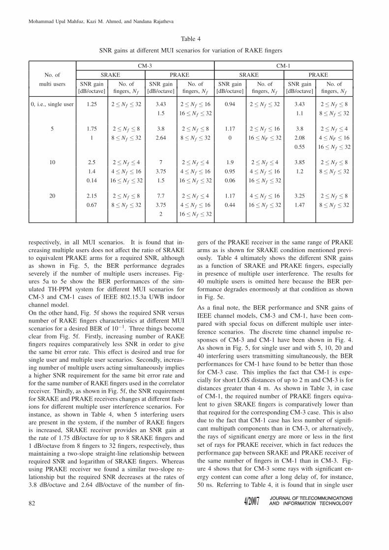
Table 4
SNR gains at different MUI scenarios for variation of RAKE fingers
CM-3 CM-1
No. of SRAKE PRAKE SRAKE PRAKE
multi users SNR gain No. of SNR gain No. of SNR gain No. of SNR gain No. of
[dB/octave] fingers, N f [dB/octave] fingers, N f [dB/octave] fingers, N f [dB/octave] fingers, N f
0, i.e., single user 1.25 2 ≤ N f ≤ 32 3.43 2 ≤ N f ≤ 16 0.94 2 ≤ N f ≤ 32 3.43 2 ≤ N f ≤ 8
1.5 16 ≤ N f ≤ 32 1.1 8 ≤ N f ≤ 32
5 1.75 2 ≤ N f ≤ 8 3.8 2 ≤ N f ≤ 8 1.17 2 ≤ N f ≤ 16 3.8 2 ≤ N f ≤ 4
1 8 ≤ N f ≤ 32 2.64 8 ≤ N f ≤ 32 0 16 ≤ NF ≤ 32 2.08 4 ≤ NF ≤ 16
0.55 16 ≤ N f ≤ 32
10 2.5 2 ≤ N f ≤ 4 7 2 ≤ N f ≤ 4 1.9 2 ≤ N f ≤ 4 3.85 2 ≤ N f ≤ 8
1.4 4 ≤ N f ≤ 16 3.75 4 ≤ N f ≤ 16 0.95 4 ≤ N f ≤ 16 1.2 8 ≤ N f ≤ 32
0.14 16 ≤ N f ≤ 32 1.5 16 ≤ N f ≤ 32 0.06 16 ≤ N f ≤ 32
20 2.15 2 ≤ N f ≤ 8 7.7 2 ≤ N f ≤ 4 1.17 4 ≤ N f ≤ 16 3.25 2 ≤ N f ≤ 8
0.67 8 ≤ N f ≤ 32 3.75 4 ≤ N f ≤ 16 0.44 16 ≤ N f ≤ 32 1.47 8 ≤ N f ≤ 32
2 16 ≤ N f ≤ 32
respectively, in all MUI scenarios. It is found that in-
creasing multiple users does not affect the ratio of SRAKE
to equivalent PRAKE arms for a required SNR, although
as shown in Fig. 5, the BER performance degrades
severely if the number of multiple users increases. Fig-
ures 5a to 5e show the BER performances of the sim-
ulated TH-PPM system for different MUI scenarios for
CM-3 and CM-1 cases of IEEE 802.15.3a UWB indoor
channel model.
On the other hand, Fig. 5f shows the required SNR versus
number of RAKE fingers characteristics at different MUI
scenarios for a desired BER of 10−1. Three things become
clear from Fig. 5f. Firstly, increasing number of RAKE
fingers requires comparatively less SNR in order to give
the same bit error rate. This effect is desired and true for
single user and multiple user scenarios. Secondly, increas-
ing number of multiple users acting simultaneously implies
a higher SNR requirement for the same bit error rate and
for the same number of RAKE fingers used in the correlator
receiver. Thirdly, as shown in Fig. 5f, the SNR requirement
for SRAKE and PRAKE receivers changes at different fash-
ions for different multiple user interference scenarios. For
instance, as shown in Table 4, when 5 interfering users
are present in the system, if the number of RAKE fingers
is increased, SRAKE receiver provides an SNR gain at
the rate of 1.75 dB/octave for up to 8 SRAKE fingers and
1 dB/octave from 8 fingers to 32 fingers, respectively, thus
maintaining a two-slope straight-line relationship between
required SNR and logarithm of SRAKE fingers. Whereas
using PRAKE receiver we found a similar two-slope re-
lationship but the required SNR decreases at the rates of
3.8 dB/octave and 2.64 dB/octave of the number of fin-
gers of the PRAKE receiver in the same range of PRAKE
arms as is shown for SRAKE condition mentioned previ-
ously. Table 4 ultimately shows the different SNR gains
as a function of SRAKE and PRAKE fingers, especially
in presence of multiple user interference. The results for
40 multiple users is omitted here because the BER per-
formance degrades enormously at that condition as shown
in Fig. 5e.
As a final note, the BER performance and SNR gains of
IEEE channel models, CM-3 and CM-1, have been com-
pared with special focus on different multiple user inter-
ference scenarios. The discrete time channel impulse re-
sponses of CM-3 and CM-1 have been shown in Fig. 4.
As shown in Fig. 5, for single user and with 5, 10, 20 and
40 interfering users transmitting simultaneously, the BER
performances for CM-1 have found to be better than those
for CM-3 case. This implies the fact that CM-1 is espe-
cially for short LOS distances of up to 2 m and CM-3 is for
distances greater than 4 m. As shown in Table 3, in case
of CM-1, the required number of PRAKE fingers equiva-
lent to given SRAKE fingers is comparatively lower than
that required for the corresponding CM-3 case. This is also
due to the fact that CM-1 case has less number of signifi-
cant multipath components than in CM-3, or alternatively,
the rays of significant energy are more or less in the first
set of rays for PRAKE receiver, which in fact reduces the
performance gap between SRAKE and PRAKE receiver of
the same number of fingers in CM-1 than in CM-3. Fig-
ure 4 shows that for CM-3 some rays with significant en-
ergy content can come after a long delay of, for instance,
50 ns. Referring to Table 4, it is found that in single user
82

Optimum receiver performance of TH-PPM ultra wideband system in multiple user interference
case and also in the presence of 5, 10, 20 multiple users,
CM-3 provides more SNR gains than in CM-1 case if the
number of SRAKE or PRAKE fingers is doubled in 2, 4,
8, 16, 32 fashion. It is found as well in all simulation re-
sults that any type of RAKE receiver with 32 fingers would
perform as good as an ideal RAKE which has a finger
number equal to the number of non-zero multipaths in the
system.
Finally, considering that increasing fingers would severely
increase receiver complexity, using an SRAKE of 8 fin-
gers has been recommended in this paper, making a trade-
off among BER performance, SNR gain and circuit comp-
lexity.
6. Conclusions
In this paper the BER performances of TH-PPM UWB
system using SRAKE and PRAKE receivers have been
compared. Performances of two channel conditions named
CM-1 and CM-3 of IEEE 802.15.3a model of UWB chan-
nel have been particularly investigated. ARAKE receiver
performance is also shown for comparison of performances
of SRAKE and PRAKE.
Results obtained through simulations show that the equiva-
lent PRAKE finger number required for maintaining same
SNR requirement varies from 2 to 3 times the original
SRAKE fingers. Increasing multiple users deteriorates
BER performance severely but has no effect on the ratio
of the number of PRAKE fingers to that of SRAKE re-
ceiver. Results also suggest that with MUI the SNR gains
due to increasing number of RAKE fingers for CM-3 chan-
nel model are different and are different from CM-1 condi-
tion, the gains for CM-1 being slightly lower than those for
CM-3. Using a maximum of 32 RAKE fingers, regardless
of being of SRAKE or PRAKE type, the ARAKE perfor-
mance can be achieved. Finally, it is recommended that
the number of SRAKE fingers must be limited to 8–10 for
getting realistically optimum BER performance.
References
[1] M.-G. Di Benedetto and G. Giancola, Understanding Ultra Wide Band
Radio Fundamentals. First Edition. Upper Saddle River: Prentice
Hall, 2004.
[2] D. Barras, F. Ellinger, and H. Jäckel, “A comparison between ultra-
wideband and narrowband transceivers”, in IEEE Wirel. 2002 Conf.,
Calgary, Canada, 2002.
[3] M. Z. Win and R. A. Scholtz, “Ultra-wide bandwidth time hopping
spread spectrum impulse radio for wireless multiple access commu-
nications”, IEEE Trans. Commun., vol. 48, pp. 679–691, 2000.
[4] A. A. D’Amico, U. Mengali, and L. Taponecco, “Performance com-
parisons between two signaling formats for UWB communications”,
in Proc. IEEE Int. Conf. Commun. ICC’04, Paris, France, 2004.
[5] D. Cassioli, M. Z. Win, F. Vatalaro, and A. F. Molish, “Performance
of low-complexity Rake reception in a realistic UWB channel”, in
Proc. IEEE Int. Conf. Commun. ICC’02, New York, USA, 2002,
pp. 763–767.
[6] “IEEE Standard for Information technology – Telecommunications
and information exchange between systems – Local and metropolitan
area networks – Specific requirements”. Part 15.3: “Wireless Medium
Access Control (MAC) and Physical Layer (PHY) Specifications
for High Rate Wireless Personal Area Networks (WPANs)”, IEEE
Std 802.15.3TM-2003.
[7] J. R. Foerster, M. Pendergrass, and A. F. Molisch, “A channel
model for ultrawideband indoor communication”, in Proc. Wirel.
Pers. Multimed. Commun. WPMC’03, Kanagawa, Japan, 2003, vol. 2,
pp. 116–120.
[8] H. Sheng, P. Orlik, A. M. Haimovich, L. J. Cimini Jr., and J. Zhang,
“On the spectral and power requirements for ultra-wideband transmis-
sion”, in Proc. IEEE Int. Conf. Commun. ICC’03, Anchorage, USA,
2003, pp. 738–742.
Mohammad Upal Mahfuz re-
ceived his B.Sc. engineering de-
gree in electrical and electronic
engineering from Bangladesh
University of Engineering and
Technology (BUET), Dhaka,
Bangladesh, in 2002 and Mas-
ter of engineering degree in
telecommunications from Asian
Institute of Technology (AIT),
Thailand, in 2005. Currently, he
is working towards his doctorate degree at University of
Calgary, Canada. His current research interests include ul-
tra wideband wireless communications, mobile commu-
nications and satellite-based positioning and navigation
systems.
e-mail: [email protected]
Telecommunications Program
Asian Institute of Technology (AIT)
PO Box: 4, Khlongluang
Pathumthani 12120, Thailand
Kazi M. Ahmed received the
M.Sc. Eng. degree in electri-
cal engineering from the Insti-
tute of Communications, Lenin-
grad, USSR, and the Ph.D. de-
gree from the University of
Newcastle, NSW, Australia, in
1978 and 1983, respectively.
Currently, he is a Professor
of telecommunications in the
School of Engineering and
Technology, Asian Institute of Technology, Pathumthani,
Thailand. His current research interests include digital sig-
nal processing, antenna array processing, tropospheric and
ionospheric propagation studies for microwave, very high
frequency-ultra high frequency communications, and satel-
lite communications.
e-mail: [email protected]
Telecommunications Program
Asian Institute of Technology (AIT)
PO Box: 4, Khlongluang
Pathumthani 12120, Thailand
83

Mohammad Upal Mahfuz, Kazi M. Ahmed, and Nandana Rajatheva
Nandana Rajatheva received
the B.Sc. degree in electronic
and telecommunication engi-
neering (with first class hon-
ors) from the University of
Moratuwa, Sri Lanka, and the
M.Sc. and Ph.D. degrees from
the University of Manitoba,
Winnipeg, Canada, in 1987,
1991, and 1995, respectively.
Currently, he is an Associate
Professor of telecommunications in the School of Engi-
neering and Technology, Asian Institute of Technology,
Pathumthani, Thailand. Earlier, he was with the Univer-
sity of Moratuwa, Sri Lanka, where he became a Professor
of electronic and telecommunication engineering in June
2003. From May 1996 to December 2001, he was with
TC-SAT as an Associate Professor. His research interests
include mobile and wireless communications, coding and
modulation techniques, space time processing for multiple
input-multiple output systems, and communication theory.
e-mail: [email protected]
Telecommunications Program
Asian Institute of Technology (AIT)
PO Box: 4, Khlongluang
Pathumthani 12120, Thailand
84