Optimum location of a shear wall in a R.C buildingshear and storey displacement of a building under...
8
INTERNATIONAL JOURNAL OF SCIENTIFIC & ENGINEERING RESEARCH, VOLUME 9, ISSUE 7, JULY-2018 ISSN 2229-5518 IJSER © 2018 http://www.ijser.org Optimum location of a shear wall in a R.C building Mr.Madhu sudhan rao.kondapalli Department of civil engineering, anil neerukonda institute of technology and sciences Sanghivalasa,visakhapatnam,andhra pradesh,531162,india. Mail id : [email protected] Abstract: Shear walls are commonly used as vertical structural element for resisting the lateral loads that may be induced by the loads due to wind and earthquake. Besides that, they also carry gravity loads. A well designed system of shear wall in building frame improves seismic performance significantly. This study aims at comparing various parameters such as storey drift, storey shear and storey displacement of a building under lateral loads based on strategic positioning of shear walls. Linear static analysis has been adopted in this paper. The software used is E-TABS. Keywords: story displacement, storey drift, linear analysis, shear wall, seismic zone. 1. Introduction Shear wall systems are one of the most commonly used lateral load resisting systems in high rise buildings. An introduction of shear wall represents a structurally efficient solution to stiffen a building, because the main function of a shear wall is to increase the rigidity for lateral load resistance. In modern tall buildings, shear walls are commonly used as a vertical structural element for resisting the lateral loads that may be induced by the effect of wind and earthquakes. Shear wall has high in-plane stiffness and strength which can be used to simultaneously resist large horizontal loads and support gravity loads, which significantly reduce lateral sway of the building and thereby reduce damage to structure. Shear walls in buildings must be symmetrically located in plan to reduce ill-effects and twist in buildings. Shear walls are like vertically-oriented wide beams which transfer these horizontal forces to the next element in the load path. These other components in the load path may be other shear walls, floors, foundation walls, slabs or footings and finally these walls carry earthquake loads downwards to the foundation. These walls generally start at foundation level and are continuous throughout the building height. It is possible for a Reinforced concrete multi-storey building to resist both the vertical and horizontal load without considering a shear wall, but the problem is beam and column sizes are become quite heavy, steel quantity requirement is also in large amount thus there is lot of congestion takes place at joints and it is difficult to place and vibrate concrete. When shear walls are situated in advantageous positions in the building, they can form an efficient lateral force resisting system by reducing lateral displacements under earthquake loads. Therefore it is very necessary to determine effective, efficient and ideal location of shear wall. It may be possible to decide the optimum or ideal location of shear wall in a building by comparing various parameters such as storey displacement, storey (or) base shear, storey drift and reinforcement requirement in columns etc of a building under lateral loads based on strategic positioning of shear wall. In our project some of the above parameters are being calculated by using software E-TABS 9.5. 2. Objectives : ▪ The main objective is to check and compare the seismic response of multi-storied building for different location of shear wall, so that one can choose the best alternative for construction in earthquake-prone area. ▪ Different location of shear wall in R.C.Building will be modelled in E-TABS software and the results in terms of storey displacement, storey drift, storey shear is compared. 3. Storey parameters ▪ Storey displacement It is the total displacement of the storey with respect to ground. Allowable displacement = Total Height Of Building 500 . ▪ Storey drift Storey drift is the displacement of one level relative to the other level above or below it: As per Clause no. 7.11.1 of IS 1893 (Part 1): 2002, the storey drift in any storey due to specified design lateral force with partial load factor of 1.0, shall not exceed 0.004 times the storey height. In Software value of storey drift is given in ratio. Storey drift ratio = Difference Between Displacement Of Two Storeys Height Of One Storey ▪ Base(or)storey shear It is the maximum expected lateral force that will occur due to seismic ground motion at the base of structure. 4. Design Loads (Types of Loads Used) 152 IJSER
Transcript of Optimum location of a shear wall in a R.C buildingshear and storey displacement of a building under...

INTERNATIONAL JOURNAL OF SCIENTIFIC & ENGINEERING RESEARCH, VOLUME 9, ISSUE 7, JULY-2018 ISSN 2229-5518
IJSER © 2018
http://www.ijser.org
Optimum location of a shear wall in a R.C building
Mr.Madhu sudhan rao.kondapalli
Department of civil engineering, anil neerukonda institute of technology and sciences
Sanghivalasa,visakhapatnam,andhra pradesh,531162,india.
Mail id : [email protected]
Abstract: Shear walls are commonly used as vertical structural element for resisting the lateral loads that may be induced by the
loads due to wind and earthquake. Besides that, they also carry gravity loads. A well designed system of shear wall in building
frame improves seismic performance significantly. This study aims at comparing various parameters such as storey drift, storey
shear and storey displacement of a building under lateral loads based on strategic positioning of shear walls. Linear static
analysis has been adopted in this paper. The software used is E-TABS.
Keywords: story displacement, storey drift, linear analysis, shear wall, seismic zone.
1. Introduction
Shear wall systems are one of the most commonly used
lateral load resisting systems in high rise buildings. An
introduction of shear wall represents a structurally efficient
solution to stiffen a building, because the main function of a
shear wall is to increase the rigidity for lateral load
resistance. In modern tall buildings, shear walls are
commonly used as a vertical structural element for resisting
the lateral loads that may be induced by the effect of wind
and earthquakes. Shear wall has high in-plane stiffness and
strength which can be used to simultaneously resist large
horizontal loads and support gravity loads, which
significantly reduce lateral sway of the building and thereby
reduce damage to structure. Shear walls in buildings must be
symmetrically located in plan to reduce ill-effects and twist
in buildings.
Shear walls are like vertically-oriented wide beams which
transfer these horizontal forces to the next element in the
load path. These other components in the load path may be
other shear walls, floors, foundation walls, slabs or footings
and finally these walls carry earthquake loads downwards to
the foundation. These walls generally start at foundation
level and are continuous throughout the building height. It is
possible for a Reinforced concrete multi-storey building to
resist both the vertical and horizontal load without
considering a shear wall, but the problem is beam and
column sizes are become quite heavy, steel quantity
requirement is also in large amount thus there is lot of
congestion takes place at joints and it is difficult to place and
vibrate concrete.
When shear walls are situated in advantageous positions in
the building, they can form an efficient lateral force resisting
system by reducing lateral displacements under earthquake
loads. Therefore it is very necessary to determine effective,
efficient and ideal location of shear wall.
It may be possible to decide the optimum or ideal location of
shear wall in a building by comparing various parameters
such as storey displacement, storey (or) base shear, storey
drift and reinforcement requirement in columns etc of a
building under lateral loads based on strategic positioning of
shear wall. In our project some of the above parameters are
being calculated by using software E-TABS 9.5.
2. Objectives :
▪ The main objective is to check and compare the
seismic response of multi-storied building for
different location of shear wall, so that one can
choose the best alternative for construction in
earthquake-prone area.
▪ Different location of shear wall in R.C.Building
will be modelled in E-TABS software and the
results in terms of storey displacement, storey drift,
storey shear is compared.
3. Storey parameters
▪ Storey displacement
It is the total displacement of the storey with
respect to ground.
Allowable displacement = Total Height Of Building
500 .
▪ Storey drift
Storey drift is the displacement of one level relative
to the other level above or below it: As per Clause
no. 7.11.1 of IS 1893 (Part 1): 2002, the storey drift
in any storey due to specified design lateral force
with partial load factor of 1.0, shall not exceed
0.004 times the storey height. In Software value of
storey drift is given in ratio.
Storey drift ratio
= Difference Between Displacement Of Two Storeys
Height Of One Storey
▪ Base(or)storey shear
It is the maximum expected lateral force that will
occur due to seismic ground motion at the base of
structure.
4. Design Loads (Types of Loads Used)
152
IJSER

INTERNATIONAL JOURNAL OF SCIENTIFIC & ENGINEERING RESEARCH, VOLUME 9, ISSUE 7, JULY-2018 ISSN 2229-5518
IJSER © 2018
http://www.ijser.org
4.1 Dead Loads (Dl) :
The first vertical load that is considered is dead
load. Dead loads are permanent or stationary loads.
Which are transferred to structure throughout the
life span. Dead load is primarily due to self weight
of structural members, permanent partition walls,
fixed permanent weight of different materials. The
calculation of dead loads of each structure are
calculated by the volume of each section and
multiplied with the unit weight.
4.2 Imposed Loads Or Live Loads (IL Or LL) :
The second vertical load that is considered in
design of a structure is imposed loads or live loads.
Live loads are either movable or moving loads
without any acceleration or impact. These loads are
assumed to be produced by the intended use or
occupancy of the building including weights of
movable partitions or furniture etc.
Live loads keep on changing from time to time.
These loads are to be suitably assumed by the
designer. It is one of the major loads in the design.
The minimum values of live loads to be assumed
are given in IS 875 (part 2)–1987. It depends upon
the intended use of the building.
4.3 Wind Loads :
Wind load is primarily horizontal load caused by
the movement of air relative to earth. Wind load is
required to be considered in structural design
especially when the height of the building exceeds
two times the dimensions transverse to the exposed
wind surface.
4.4 Earthquake Loads (Or) Seismic Loads:
The seismic (or) earth quake loads on the structure
during an earthquake result from inertia forces
which were created by ground accelerations. The
magnitude of these loads is a function of the
following factors: mass of the building, the
dynamic properties of the building, the intensity,
duration, and frequency content of the ground
motion, and soil-structure interaction.
5. Seismic Zones of India:
The earthquake zoning map of India divides India
into 4 seismic zones (Zone 2, 3, 4 & 5). According
to the present zoning map, Zone 5 expects the
highest level of seismicity whereas Zone 2 is
associated with the lowest level of seismicity.
Table 1 zone factors
Zone no Factors
5 0.36
4 0.24
3 0.16
2 0.1
6. Building details
Table 2 Building Details
S.no Particulars Data
1 No. Of storeys 15
2 Plan dimension 20x20 m
3 Storey height 3.0 m
4 Grade of concrete M25,M30
5 Grade of steel Fe415
6 Thickness of slab 0.2 m
7 Beam size 0.6x0.6 m
8 Column size 0.6x0.6 m
9 Seismic zone 2
10 Seismic factor 0.1
11 Earthquake load for
type2
As per IS
1893:2002
12 Top storey load 1.5 KN/m2
13 Intermediate storey
load
3.0 KN/m2
14 Floor/cover load 1.0 KN/m2
7. Material properties:
Strength of concrete
(fck) = 30 N/mm2
Yield strength of main reinforcement
(fy) = 415N/mm2
Yield strength of shear reinforcement
(fys) = 415 N/mm2
Young’s modulus of concrete
(Ec) = 3x10⁴ N/mm2
8. Loading:
Table 3 load cases
Load cases Type Details
Dead Dead load Use self-weight
multiplier
Floor Live load Slab: 200mm
Storey Live load
Slab: 200 mm
Beams:
600x600 mm
Earthquake Seismic load
Is:1893:2002
response
reduction
factor = 5
153
IJSER

INTERNATIONAL JOURNAL OF SCIENTIFIC & ENGINEERING RESEARCH, VOLUME 9, ISSUE 7, JULY-2018 ISSN 2229-5518
IJSER © 2018
http://www.ijser.org
9. Model in E-TABS
Fig 1 3-D view of model
Fig 2 floor plan
Fig 3 elevation
10. Models:
The following are the models to be considered for
analysis of a R.C building with shear walls at various
locations.
i. Bare frame (no shear walls) M1
ii. Shear wall at central core M2
iii. Shear walls at corners M3
iv. Shear walls at edge faces M4
v. Shear walls at core + corners M5
vi. Shear walls at core + edges M6
11. Results and discussions
After analysis done for the building without shear walls
the various storey parameters are compared with the
models having shear walls placing at strategic
positions. The following results are evaluated below by
comparing the storey parameters.
11.1 Comparison Of A Parameter (Storey
Displacement) :
154
IJSER
INTERNATIONAL JOURNAL OF SCIENTIFIC & ENGINEERING RESEARCH, VOLUME 9, ISSUE 7, JULY-2018 ISSN 2229-5518
IJSER © 2018
http://www.ijser.org
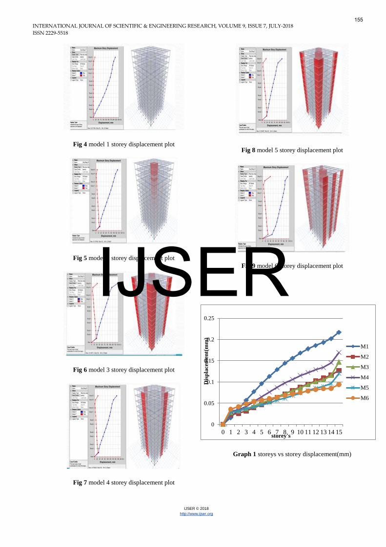
Fig 4 model 1 storey displacement plot
Fig 5 model 2 storey displacement plot
Fig 6 model 3 storey displacement plot
Fig 7 model 4 storey displacement plot
Fig 8 model 5 storey displacement plot
Fig 9 model 6 storey displacement plot
Graph 1 storeys vs storey displacement(mm)
0
0.05
0.1
0.15
0.2
0.25
0 1 2 3 4 5 6 7 8 9 10 11 12 13 14 15
Dis
pla
cem
ent(
mm
)
storey's
M1
M2
M3
M4
M5
M6
155
IJSER

INTERNATIONAL JOURNAL OF SCIENTIFIC & ENGINEERING RESEARCH, VOLUME 9, ISSUE 7, JULY-2018 ISSN 2229-5518
IJSER © 2018
http://www.ijser.org
Graph 2 storeys vs storey drift
Bar chart 1 storeys vs base shear (kn)
Table 4 Combination of storey displacement plots of above six models
Storey’s M1 M2 M3 M4 M5 M6
no’s displacement(mm) displacement(
mm)
displacement(
mm)
displacement(m
m)
displacement(m
m)
displacement(m
m)
15 0.217 0.127 0.147 0.169 0.12 0.094
14 0.202 0.116 0.115 0.145 0.096 0.085
13 0.193 0.109 0.105 0.134 0.089 0.084
12 0.186 0.102 0.1 0.129 0.085 0.082
11 0.178 0.095 0.094 0.122 0.08 0.079
10 0.168 0.088 0.086 0.115 0.074 0.075
9 0.156 0.08 0.079 0.106 0.068 0.072
8 0.144 0.072 0.072 0.097 0.062 0.068
7 0.129 0.064 0.064 0.087 0.057 0.064
6 0.113 0.055 0.057 0.076 0.051 0.061
5 0.096 0.047 0.05 0.065 0.046 0.057
4 0.077 0.039 0.044 0.054 0.041 0.054
3 0.057 0.032 0.037 0.043 0.037 0.049
2 0.036 0.026 0.032 0.034 0.032 0.042
1 0.016 0.023 0.028 0.031 0.029 0.036
0 0 0 0 0 0 0
0
0.000002
0.000004
0.000006
0.000008
0.00001
0.000012
0.000014
0.000016
0 1 2 3 4 5 6 7 8 9 101112131415
Sto
rey
Dri
ft
Storey's
M1
M2
M3
M4
M5
M60
5
10
15
20
25
30
35
40
45
15 14 13 12 11 10 9 8 7 6 5 4 3 2 1 0
Ba
se S
hea
r (
KN
)
Storey’s
M1
M2
M3
M4
M5
M6
156
IJSER

INTERNATIONAL JOURNAL OF SCIENTIFIC & ENGINEERING RESEARCH, VOLUME 9, ISSUE 7, JULY-2018 ISSN 2229-5518
IJSER © 2018
http://www.ijser.org
Table 5 comparison of models to model 1 by % reduction in displacement
Sto rey ’s M2 M3 M4 M5 M6
No ’s% red u ctio n
in d isp lacemen t
% red u ctio n in
d isp lacemen t
% red uction in
d isp lacemen t
% red uction in
d isp lacemen t
% red uction in
d isp lacemen t
1 5 4 1 .4 7 3 2 .2 5 2 2 .1 1 4 4 .7 5 6 .6 8
1 4 4 2 .5 7 43 .06 28 .21 52 .47 57 .92
1 3 4 3 .5 2 4 5 .5 9 3 0 .5 6 5 3 .8 8 5 6 .4 7
1 2 4 5 .1 6 1 4 6 .2 3 3 0 .6 4 5 4 .3 0 5 5 .9 1
11 46 .62 4 7 .1 9 1 3 1 .4 6 5 5 .0 5 5 5 .6 1
1 0 4 7 .6 1 4 8 .8 0 3 1 .5 4 5 5 .9 5 5 5 .3 5
9 4 8 .7 1 4 9 .3 5 3 2 .0 5 5 6 .4 1 5 3 .8 4
8 5 0 5 0 3 2 .6 3 5 6 .9 4 5 2 .7 7
7 5 0 .3 8 5 0 .3 8 3 2 .5 5 5 5 .8 1 5 0 .3 8
6 5 1 .3 2 4 9 .5 5 3 2 .7 4 5 4 .8 6 4 6 .0 1
5 5 1 .0 4 1 47 .91 32 .291 52 .083 40 .625
4 4 9 .3 5 4 2 .8 5 2 9 .8 7 4 6 .7 5 2 9 .8 7
3 4 3 .8 5 3 5 .0 8 2 4 .5 6 3 5 .0 8 1 4 .0 3
2 27 .77 1 1 .1 1 5 .5 5 1 1 .1 1 -1 6 .6 6
1 -4 3 .7 5 -7 5 -9 3 .7 5 -8 1 .2 5 -1 2 5
0 0 0 0 0 0
157
IJSER

INTERNATIONAL JOURNAL OF SCIENTIFIC & ENGINEERING RESEARCH, VOLUME 9, ISSUE 7, JULY-2018 ISSN 2229-5518
IJSER © 2018
http://www.ijser.org
Table 6 combination of storey drifts of above six models
STOREYS M1 M2 M3 M4 M5 M6
15 8.00E-06 6.00E-06 1.40E-05 1.30E-05 1.10E-05 5.00E-06
14 3.00E-06 3.00E-06 6.00E-06 4.00E-06 5.00E-06 4.00E-06
13 2.00E-06 3.00E-06 4.00E-06 3.00E-06 3.00E-06 3.00E-06
12 3.00E-06 3.00E-06 3.00E-06 3.00E-06 3.00E-06 3.00E-06
11 3.00E-06 3.00E-06 3.00E-06 4.00E-06 3.00E-06 3.00E-06
10 4.00E-06 3.00E-06 3.00E-06 4.00E-06 3.00E-06 3.00E-06
9 4.00E-06 4.00E-06 4.00E-06 4.00E-06 3.00E-06 3.00E-06
8 5.00E-06 4.00E-06 4.00E-06 5.00E-06 3.00E-06 4.00E-06
7 5.00E-06 4.00E-06 4.00E-06 5.00E-06 3.00E-06 4.00E-06
6 6.00E-06 4.00E-06 4.00E-06 5.00E-06 3.00E-06 3.00E-06
5 6.00E-06 4.00E-06 4.00E-06 5.00E-06 3.00E-06 3.00E-06
4 7.00E-06 3.00E-06 3.00E-06 4.00E-06 3.00E-06 2.00E-06
3 7.00E-06 3.00E-06 3.00E-06 4.00E-06 2.00E-06 3.00E-06
2 8.00E-06 3.00E-06 4.00E-06 4.00E-06 4.00E-06 5.00E-06
1 5.00E-06 8.00E-06 9.00E-06 1.00E-05 1.00E-05 1.20E-05
0 0 0 0 0 0 0
12. Conclusions:
1. Shear wall placing at adequate locations is more
significant in case of base shear and displacement.
2. It is observed that horizontal displacement of a 15
storey building with shear wall at core+edge
faces(x-dir) of building is lesser when compared to
other models.
3. Larger the width of shear wall , the larger will be
the resistances against lateral forces.
4. The graph of displacement reflects that for structure
having core shear wall the displacement is least.
The maximum structural displacement for 15 storey
building is 0.271mm for bare frame structure and
least value is 0.127mm for structure with shear wall
at core+edge(x-dir) location. The displacement
observed is within the limits specified in IS
1893:2002 (Part I).
5. Base shear is inversely proportional to the storey
displacement. Hence the model with least storey
displacement have the maximum base shear value.it
means to resists the maximum lateral force.
6. From the results above it was possible to notify the
optimum location of a shear wall by approximate
quantitative analysis. since it was model 6 having
shear walls at (core+edges). However the edges
direction is parallel to the earth quake load applied.
13. Future scope:
1. In this paper i have considered building of 15
storeys only, we can also consider buildings with
more number of storeys.
2. I have studied only three major parameters i.e..
storey displacement, storey drift and storey (or)
base shear. The volume of work undertaken in this
study is limited to comparison of seismic response
parameters in a building with different shear wall
locations using linear analysis. The study could be
extended by including various other parameters
such as torsional effects and soft storey effects in a
building. Non-linear dynamic analysis may be
carried out for further study for better and realistic
evaluation of structural response under seismic
forces .
158
IJSER

INTERNATIONAL JOURNAL OF SCIENTIFIC & ENGINEERING RESEARCH, VOLUME 9, ISSUE 7, JULY-2018 ISSN 2229-5518
IJSER © 2018
http://www.ijser.org
3. In this paper I considered the building with regular
plan and assumes seismic load be acts in a
unidirection.it also to carry out for irregular plan
and load acts in a multi directional.
14. References:
[1] Anshumn. S, Dipendu Bhunia, Bhavin
Rmjiyani (2011), “Solution of shear wall
location in Multi-storey building.”
International Journal of Civil Engineering Vol.
9, No.2Pages 493-506.
[2] Anuj Chandiwala (2012), “Earthquake
Analysis of Building Configuration with
Different Position of Shear Wall”,
International Journal of Emerging Technology
and Advanced Engineering ISSN 2250-2459,
ISO 9001:2008 Certified Journal, Volume 2,
Issue 12, December 2012, Adhoc Lecturer in
Sarvajanik College of Engineering &
Technology, Athvalines, Surat, Gujarat, India.
[3] A.B. Karnale and Dr.D.N. Shinde (2015),
“Comparative Seismic Analysis of High Rise
and Low Rise RCC Building with Shear
Wall”, International Journal of Innovative
Research in Science, Engineering and
Technology, September 2015.
[4] Chen Qin and Qian Jiaru (2002), “Static
inelastic analysis of RC shear walls”,
department of civil engineering, Tsinghua
University, Beijing 100084, China.
[5] IS. 456-2000, Indian standard Plain and
Reinforced Concrete code of practice, Bureau
of Indian standards, New Delhi.
[6] IS 1893 (Part 1): (2002) Indian Standard
Criteria for Earthquake Resistant Design of
Structures General Provisions and Buildings.
[7] Pavan K.E., Naresh A., Nagajyothi M. and
Rajasekhar M., (2014), “Earthquake analysis
of multi storied residential building - a case
study”, Int. Journal of Engineering Research
and Applications, Vol. 4 (11), 59-64.
[8] P. P. Chandurkar and Dr. P. S. Pajgade
(2013), “Seismic Analysis of RCC Building
with and Without Shear Wall”, International
Journal of Modern Engineering Research
(IJMER) www.ijmer.com Vol. 3, Issue. 3,
May - June 2013.
[9] Shah M. D and Patel S. B., (2011),
“Nonlinear static analysis of R.C.C. frames” -
Software implementation ETABS 9.7,
National Conference on Recent Trends in
Engineering & Technology, 1-6.
[10] Shaik Kamal Mohammed Azam,
Vinod Hosur,(2013), “Seismic
Performance Evaluation of Multistoried
RC framed buildings with Shearwall”,
International Journal of Scientific &
Engineering Research.
[11] S.K.Duggal (2007), “Earthquake
resistant design of structures” Oxford
university press 2, New Delhi ISBN-
13:978-0-19-568817-7.
[12] S. M. Yarnal, S.S. Allagi, P.M. Topalakatti
and A. A. Mulla (2015), “Non-Linear
Analysis of Asymmetric Shear Wall with
Openings”, International Journal of
Engineering Research & Technology (IJERT)
Vol. 4 Issues 08, August-2015.
[13] Venkata Sairam Kumar.N, Surendra
Babu.R, Usha Kranti.J(2014),“Shear walls –
A review”,International Journal of Innovative
Research in Science, Engineering and
Technology, Feb 2014.
159
IJSER


![Seismic Analysis of Multi-Storey R.C Structural Frames ... · planned and analyzed with the help of STAAD-Pro Software. [2] P.V. Prasad &T.RajaSekhar (2014),passed out study on the](https://static.fdocuments.in/doc/165x107/5e81226515bd606db5313301/seismic-analysis-of-multi-storey-rc-structural-frames-planned-and-analyzed.jpg)