Optimum Design and Numerical Analysis of Horizontal Axis ...
8
Optimum Design and Numerical Analysis of Horizontal Axis Wind Turbine Composite Blades Ahmed S. A. Abou Taleb # , Basman N. El-Hadid † , Badr S. N. Azzam * , Sayed M. Metwalli * # Basic Science Dept ,iAEMS Academy, Media Production City, 6 of October, Egypt [email protected] † Aeronautical Engineering Dept, Cairo University Cairo University, Giza, Egypt [email protected], * Mechanical Design & Production Dept, Cairo University Cairo University, Giza, Egypt [email protected] & [email protected] Abstract— This paper presents a methodology for an optimum design of laminated glass-fiber reinforced epoxy-matrix composite horizontal axis wind turbine (HAWT) blades based on genetic algorithm (GA). Two different models of blade structures have been manipulated. The first model is a laminated structure with 10% tailing edge spar, while, the other one is a laminated structure with 5% leading and 5% tailing edges spars. Both models spars fabricated from the same material of the outer layer. The objective of that optimization problem is to maximize the load-carrying capacity under different loads. The number of layers, fiber orientations, fiber volume fractions and layer thickness are considered as the primary optimization variables. Simplified micro-mechanics equations are used to estimate the stiffness and strength of each layer using the optimization variables and material constituent’s properties. The lamina stresses for thin composite slips subjected to force and/or moment resultants are determined using the classical lamination theory. The first-ply failure strength is computed using the Tsai– Wu failure criterion. A genetic algorithm is adapted to obtain the optimal design for HAWT model problem. Four different case studies are carried out, corresponding to upper, lower, right-side and left-side blade positions. The results of the optimization work showed that the most critical position is the lower one. The optimized blade in that critical case is composed of 8 layers in the first model and 10 layers in the other one. The optimized composite structure blades have been verified numerically to get the stresses and deformations resulted in them for the purpose of design safety under the different applied loads. Keywords— Horizontal axis wind turbine, Composite material (CM), blade, Genetic algorithm, and Optimization. I. INTRODUCTION One of the important applications of composite materials is the wind turbine blade fabricated from composite materials. Thus, it was an obvious step, even at the beginning of modern wind energy technology, to use this material also for the construction of rotor blades. Developing the wind turbine blades fabricated from composite material has been linked up with two paths of development. The first path includes the requirements for strength and stiffness as high as in aviation. While, the other path is the weight reduction which is a predominant role in reducing the materials and manufacturing processes of the wind turbines [1], [2]. The merit of having being one of the first to make the rotor blades of a wind turbine from composites is due to Hütter [3]. Hütter designed the 17-m-long rotor blades in glass fiber composite technology as early as 1959. In the following years, glass fiber reinforced composite material became the preferred material for wind turbine rotor blades. In the beginning, blades with wound spars and laminated outer shells were produced for the smaller Danish turbines using the cheaper polyester as a matrix material [4]. Venkataraman and Haftka [5] described a genetic algorithm (GA) as a most popular method for the combinatorial optimization of laminate stacking sequence. GAs are contemporary search techniques developed by Holland [6] that mimics the evolutionary principles and chromosomal processing in natural genetics. Soremekun et al. [7] utilized a GA with generalized elitist selection to maximize the bending and coupling of a laminated cantilever beam. Park et al. [8] analyzed symmetric composite laminates using a shear deformation theory and the Tsai–Hill failure criterion to obtain optimal designs of symmetric composite laminates subject to various loading and boundary conditions. In the present work, an improved methodology for the optimization of fiber reinforced composite materials to maximize the load carrying capacity via the layer-wise tailoring of fiber orientations, fiber volume fraction, and layers’ thickness is described. The stiffness and strengths of each lamina are estimated using Chamis’ simplified micromechanics equations [9]. The classical lamination theory is utilized to determine the lamina stresses for thin laminates subjected to force and/or moment resultants and the first-ply failure load is obtained using the Tsai–Wu failure criterion. An integer-coded GA, based on the elitist non- dominated sorting GA [10], is implemented to obtain optimum designs for conflicting objective. A novel feature of the proposed methodology is the incorporation of an automatic termination criterion for GA. It keeps track of the number of new designs that are added to a historical archive
Transcript of Optimum Design and Numerical Analysis of Horizontal Axis ...

Optimum Design and Numerical Analysis of Horizontal Axis Wind Turbine Composite Blades
Ahmed S. A. Abou Taleb#, Basman N. El-Hadid†, Badr S. N. Azzam*, Sayed M. Metwalli*
#Basic Science Dept ,iAEMS Academy, Media Production City, 6 of October, Egypt
[email protected] †Aeronautical Engineering Dept, Cairo University
Cairo University, Giza, Egypt [email protected],
*Mechanical Design & Production Dept, Cairo University Cairo University, Giza, Egypt
[email protected] & [email protected]
Abstract— This paper presents a methodology for an optimum design of laminated glass-fiber reinforced epoxy-matrix composite horizontal axis wind turbine (HAWT) blades based on genetic algorithm (GA). Two different models of blade structures have been manipulated. The first model is a laminated structure with 10% tailing edge spar, while, the other one is a laminated structure with 5% leading and 5% tailing edges spars. Both models spars fabricated from the same material of the outer layer. The objective of that optimization problem is to maximize the load-carrying capacity under different loads. The number of layers, fiber orientations, fiber volume fractions and layer thickness are considered as the primary optimization variables. Simplified micro-mechanics equations are used to estimate the stiffness and strength of each layer using the optimization variables and material constituent’s properties. The lamina stresses for thin composite slips subjected to force and/or moment resultants are determined using the classical lamination theory. The first-ply failure strength is computed using the Tsai–Wu failure criterion. A genetic algorithm is adapted to obtain the optimal design for HAWT model problem. Four different case studies are carried out, corresponding to upper, lower, right-side and left-side blade positions. The results of the optimization work showed that the most critical position is the lower one. The optimized blade in that critical case is composed of 8 layers in the first model and 10 layers in the other one. The optimized composite structure blades have been verified numerically to get the stresses and deformations resulted in them for the purpose of design safety under the different applied loads. Keywords— Horizontal axis wind turbine, Composite material (CM), blade, Genetic algorithm, and Optimization.
I. INTRODUCTION One of the important applications of composite materials is
the wind turbine blade fabricated from composite materials. Thus, it was an obvious step, even at the beginning of modern wind energy technology, to use this material also for the construction of rotor blades. Developing the wind turbine blades fabricated from composite material has been linked up with two paths of development. The first path includes the requirements for strength and stiffness as high as in aviation. While, the other path is the weight reduction which is a
predominant role in reducing the materials and manufacturing processes of the wind turbines [1], [2].
The merit of having being one of the first to make the rotor blades of a wind turbine from composites is due to Hütter [3]. Hütter designed the 17-m-long rotor blades in glass fiber composite technology as early as 1959. In the following years, glass fiber reinforced composite material became the preferred material for wind turbine rotor blades. In the beginning, blades with wound spars and laminated outer shells were produced for the smaller Danish turbines using the cheaper polyester as a matrix material [4].
Venkataraman and Haftka [5] described a genetic algorithm (GA) as a most popular method for the combinatorial optimization of laminate stacking sequence. GAs are contemporary search techniques developed by Holland [6] that mimics the evolutionary principles and chromosomal processing in natural genetics. Soremekun et al. [7] utilized a GA with generalized elitist selection to maximize the bending and coupling of a laminated cantilever beam. Park et al. [8] analyzed symmetric composite laminates using a shear deformation theory and the Tsai–Hill failure criterion to obtain optimal designs of symmetric composite laminates subject to various loading and boundary conditions.
In the present work, an improved methodology for the optimization of fiber reinforced composite materials to maximize the load carrying capacity via the layer-wise tailoring of fiber orientations, fiber volume fraction, and layers’ thickness is described. The stiffness and strengths of each lamina are estimated using Chamis’ simplified micromechanics equations [9]. The classical lamination theory is utilized to determine the lamina stresses for thin laminates subjected to force and/or moment resultants and the first-ply failure load is obtained using the Tsai–Wu failure criterion. An integer-coded GA, based on the elitist non-dominated sorting GA [10], is implemented to obtain optimum designs for conflicting objective. A novel feature of the proposed methodology is the incorporation of an automatic termination criterion for GA. It keeps track of the number of new designs that are added to a historical archive

of non-dominated individuals and terminates the algorithm when it reaches the point of diminishing returns [11].
II. PROPLEM METHODOLOGY A rectangular cartesian coordinate system x, y and z is used
to describe the infinitesimal deformations of an N-layer laminated composite material as shown in Fig. 1, in the unstressed reference configuration. The total thickness of the laminate is H and the bottom and top surfaces are located at z=-H/2 and H/2, respectively. Lamina n consists of a macroscopically homogeneous fiber-reinforced composite material with fiber volume fraction Vf
(n), extending from z(n-1) to z(n) in the z-direction. The principal fiber direction is oriented at an angle of φ(n) to the x-axis. In the present problem formulation, the Vf
(n), φ(n), h(n) (=z(n) - z(n-1)) of each lamina, and the total number of layers N, are treated as the optimization variables.
The classical lamination theory (CLT) as applied in
analyzing the current models is applicable to continuous fiber laminated composite only. Derivations of CLT follow the classical procedures cited in earlier publications [12]. To maximize the failure load of composite laminates, Tsai–Wu failure criterion [13] has been applied to analyze the failure of laminated composite blades to obtain a safe design.
A GA begins its search with a population of random individuals. Each member of the population possesses a chromosome, which encodes certain characteristics of the individual. In the present case, an individual member of the population corresponds to a particular laminate design and its chromosome consists of the fiber orientations, fiber volume fractions, lamina thicknesses and layers number. The algorithm systematically analyzes each individual in the population of designs according to set specifications and assigns it a fitness rating which reflects the designer’s goals. This fitness rating is then used to identify the structural designs that perform better than others, thereby enabling the GA to determine the designs that are weak and must be
eliminated using the reproduction operator. The remaining, more desirable genetic material is then utilized to create a new population of individuals. This is performed by applying two more operators similar to natural genetic processes, namely gene crossover and gene mutation. The process is iterated over many generations in order to obtain optimal designs. The evolutionary technique provides major benefits over traditional gradient-based optimization routines, such as nominal insensitivity to problem complexity and the ability to seek out global rather than local optima [14]-[16].
A laminate design, y, is represented by a real-valued array which consists of the Vf
(n), φ(n), and h(n), of the laminae { }{ }{ }{ })()2()1()()2()1()()2()1( maxmaxmax ...,,,,...,,,,...,,, NNN
fff hhhVVVy ϕϕϕ= (1) where Vf : fiber volume fraction, φ: fiber orientation angle,
h: layer thickness and N: number of layers. Thus, there are 3Nmax decision variables. It is possible for
some of the laminae to have zero thicknesses, in which case the corresponding Vf, φ and h are simply deleted from the array y.
An optimization problem, which has an objective function that needs to be maximized, is stated in the following form:
MmygtosubjectyFMaximize
yFind
m ,...,2,10)()(
=≤
(2)
where F(y) is the objective function and gm(y) is the M constraints.
In problems that involve one or more objective functions that need to be minimized, only those objective functions are multiplied by -1 to transform it into one in which all the objective functions are maximized. Equality constraints, although not explicitly stated, can be handled by converting them to inequality constraints [17].
A. Genetic Coding In current implementation for the optimal design of
laminates, integers are used to represent the individual decision variables as follows:
{ }{ }{ }{ })()2()1()()2()1()()2()1( maxmaxmax ...,,,,...,,,,...,,, NNNvvvy ηηηθθθ= (3) where v(n), θ(n) and η(n) are integers ranging from 0 to NV, 0
to Nφ and 0 to Nh, and the transformations from integer coded values to the decision variables are,
( )
( )
( ) ,
,
,
minminmax)(
)(
minminmax)(
)(
minminmax
)()(
hhhN
h
N
VVVNvV
h
nn
nn
fffV
nn
ff
+−=
+−=
+−=
η
ϕϕϕθ
ϕϕ
(4)
B. Genetic Algorithm The optimal designs are obtained using a suggested integer-
coded version of the non-dominated sorting GA (NSGA-II) [18]. The NSGA-II algorithm is modified to include an archive of the historically non-dominated individuals (Ht). A schematic of the process that is used to update the parent population (Pt), child population (Qt), and historical archive of
Fig. 1: Representation of a thin laminated composite shell subjected to force
and moment resultants, with a close-up view of the shell’s cross section.

non-dominated solutions (Ht), from generation t to t +1 is shown in Fig. 2.
III- OPTIMIZATION PROBLEM FORMULATION
A. Mathematical Formulas
1) Problem Objective Function: The objective function could be defined as follows:
[ ] )],([minmin2,2
−+−∈ ++= babaHHzf σσσσσ (5)
where σf: final stress, σa: axial stress and σb: bending stress. Under different sources of loading which can be
categorized as follows: • Aerodynamic loads, • Gravitational loads, and • Inertia loads (centrifugal effect).
2) Aerodynamic Loads Constraints: The aerodynamic design of wind turbine blade requires more than knowledge of the elementary physical laws of energy conversion. The designer faces the problem of finding the relationship between the actual shape of the blade and its aerodynamic properties.
The standard deviation of tip displacement in combination with the blade mode shape yields an inertial loading distribution from which the standard deviation of the resulting bending moment at any position along the blade may be calculated. In particular, the standard deviation of the root bending moment may be expressed in terms of the mean root bending moment as follows:
11
1111
1 ..)()(2
2 Mx
MsxuuM
xnknR
UMλ
σλ
δ
πσσ== (6)
where, σM1: First-mode resonant bending moment at blade root, M: bending moment, σu: standard deviation of fluctuating component of wind in along-wind direction, U: wind speed, δ: logarithmic decrement of combined aerodynamic and structural dambing, Ru(n1): normalized power spectral density, ksx(n1): size reduction factor, σM1: , and x1: first mode component of steady tip displacement.
∫∫
∫=
R
R
R
M drrurcrdrrcm
rdrrurm
01
01
01
1 )()()(
)()(λ (7)
where, m: mass per unit length, u1: fluctuating component of wind speed, r: radius, and c: chord length.
The standard deviation of the quasi-static bending moment fluctuation or bending moment background response is expressed in terms of the mean bending moment by
SMBuMB KUMσσ 2= (8)
where, σMB: bending moment background, and KSMB is usually slightly less than unity because the blade length is small compared with the integral length scale of longitudinal turbulence measured across the wind direction. The load distribution across the blade can be calculated from the curves and tabulated data. Figure 3 shows the coefficient of pressure for the selected blade at first, fifth and ninth stations. The blade in question is for a rotor producing 100 kW at a rated speed of 10 m/sec. This blade is a commercial turbine manufactured by glass fiber reinforced epoxy and has airfoil profile, as shown in figures 5 and 6. The loading was obtained by a simple blade element momentum calculation to include the local flow angles of attack from which the pressure distribution is easily obtained using two-dimensional wind tunnel data for the airfoils in question [2].
The variance of the total root bending moment fluctuations
is equal to the sum of the resonant and background response variances, i.e.,
221
2MBMM σσσ += (9)
where, σM1:bending moment. 2111 )()(
22 MsxuSMBuM nKnRKUM
λδπσσ
+= (10)
Wind fluctuations at frequencies close to the first flap-wise mode blade natural frequency excite resonant blade oscillations and result in additional, inertial loadings over and above the quasi-static loads that would be experienced by a completely rigid blade. As the oscillations result from fluctuations of the wind speed about the mean value, the standard deviation of resonant tip displacement can be expressed in terms of the wind turbulence intensity and the
Fig. 2: Schematic of the controlled elitist NSGA II multi-criteria GA with termination criteria based on a non-constrain-dominated historical archive.
Fig. 3: Pressure coefficient distribution across the airfoil.

normalized power spectral density at the resonant frequency, 2
11 /)(.)( uuu nSnnR σ= ,as follows [19]-[21]:
)111
1 ()(2
2 nKnRUx sxuux
δ
πσσ= (11)
3) Gravity Load Constraint: The rotor blade weight generates alternating tensile and compressive forces along the length of the blade and large alternating bending moments around the chord-wise and flap-wise axes in the blades over one rotor revolution. The significance of this gravitational loading increases from the blade tip to the root, i.e. in the opposite direction from the influence of the aerodynamic loads. Thus, together with wind turbulence, the influence of the gravitational forces becomes the dominant factor for the bending strength of the rotor blades [20]. The blade weight was given by:
NcompNVm ρ×=sec (12)
( ) mfffcomp VV ρρρ −+= 1 (13)
4) Centrifugal Loads Constraint: Centrifugal forces are not very significant in wind rotors, due to their comparatively low rotational speed. This is in contrast to helicopter rotors, where blade strength and dynamic behavior are determined by the centrifugal forces. The centrifugal force was given by [20]:
∫=0
)()( sec2r
rirdrrmrC ω
(14)
5) Manufacturing Constraints The manufacturing constraints are usually defined as follows [22]:
7.05.0 ≤≤ fV (15)
totalhh ≤≤01.0 (16) 00 9090 ≤≤− ϕ (17)
B. Problem Modelling:
1) Model Problem 1 (10% Tailing Edge Spar Blade Structure): In this model, each layer has different length with difference in Vf, φ, and h for the same (GFRE). The blade length is divided into 9 stations. The tailing edge spar has the same material structure fabricated the outer layer with 10% of the chord length.
Four different blade positions are studied (upper, lower, right side and left side positions) with the outer layers in both the upper and lower divisions are equal to the blade length. The problem is solved to get the optimum blade structure (N, Vf, φ, and h).
Case One: Upper Blade Position: In this case, the blade is subjected to bending moment due to aerodynamic pressure load applied on the blade surface and two opposite axial load, the weight of the blade which is in negative direction (compression) and the centrifugal load which is in the positive direction (tension).
Case Two: Lower Blade Position: In this case, the blade is subjected to bending moment due to aerodynamic pressure load applied on the blade surface and two axial loads in the
same direction, the weight of the blade and the centrifugal load which are in the negative direction (tension).
Case Three: Right Side Blade Position: In this case, the blade is subjected to bending moment due to aerodynamic pressure load applied on the blade surface and the blade weight, and one axial load due to the centrifugal load in the negative direction (tension).
Case Four: Left Side Blade Position: In this case, the blade is subjected to bending moment due to aerodynamic pressure load applied on the blade surface and the blade weight, and one axial load due to the centrifugal load in the negative direction (tension).
2) Model Problem 2 (5% Tailing and 5% Leading Edges Spars Blade Structure):This model problem is same as in model problem 1 except that both tailing and leading edges spars equals 5% of the chord length.
Case One: Upper Blade Position: This case subject to the same loads conditions as in model 1 upper position.
Case Two: Lower Blade Position: This case subject to the same loads conditions in model 1 lower position.
Case Three: Right Side Blade Position: This case subject to the same loads conditions in model 1 right side position.
Case Four: Left Side Blade Position: This case subject to the same loads conditions in model 1 left position.
IV. OPTIMIZATION RESULTS In this section, the results of optimal design studies
performed on considered models have been presented. The lamina thickness h(n) can vary from hmin = 0 to hmax = h. Optimal values are sought for the Vf, φ and h. The GA parameters were tuned by studying the convergence of the algorithm for the model problems. It was found that controlled elitism enhanced the ability for the algorithm to seek out the entire optimal front. In consideration of the overall accuracy of the search versus computation time, the termination criterion parameters are chosen to be G = 100 generations, ε = 0.01 and δ = 0.005. That is, the algorithm is terminated when it is unable to find a single, new, historically non-dominated, less crowded solution over a span of 100 generations that changes the average crowding distance of the historical archive by 0.5%.
In current models, Glass fiber reinforced epoxy (GFRE) laminates have been considered. Mechanical properties of the constituent materials are provided in Table 1.
TABLE 1
MECHANICAL PROPERTIES OF SELECTED FIBER AND MATRIX [22]
Glass Fiber [E-Glass] Epoxy
E1 (GPa) 76.0 3.5 E2 (GPa) 8.7 3.5 G12 (GPa) 3.24 1.3 ν12 0.30 0.35
Sut (MPa) 2600 103 Suc (MPa) -2360 -241 Sus (MPa) - 89.6 ρ (Kg/m3) 2540 1210
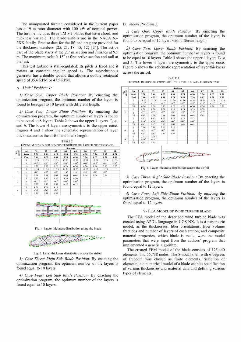
The manipulated turbine considered in the current paper has a 19 m rotor diameter with 100 kW of nominal power. The turbine includes three LM 8.2 blades that have chord, and thickness variable. The blade airfoils are in the NACA 63-2XX family. Precise data for the lift and drag are provided for the thickness numbers {25, 21, 18, 15, 12} [24]. The active part of the blade starts at the 2.7 m section and finishes at 9.5 m. The maximum twist is 150 at first active section and null at the last.
This test turbine is stall-regulated. Its pitch is fixed and it rotates at constant angular speed ω. The asynchronous generator has a double wound that allows a double rotational speed of 35.6 RPM or 47.5 RPM.
A. Model Problem 1:
1) Case One: Upper Blade Position: By enacting the optimization program, the optimum number of the layers is found to be equal to 10 layers with different length.
2) Case Two: Lower Blade Position: By enacting the optimization program, the optimum number of layers is found to be equal to 8 layers. Table 2 shows the upper 4 layers Vf, φ, and h. The lower 4 layers are symmetric to the upper once. Figures 4 and 5 show the schematic representation of layer thickness across the airfoil and blade length.
TABLE 2 OPTIMUM DESIGN FOR COMPOSITE STRUCTURE: LOWER POSITION CASE.
Layer N
o.
Stations No. 01 02 03 04 05 06 07 08 09
Start 2.70 3.46 4.22 4.98 5.74 6.50 7.26 8.02 8.78 End 3.46 4.22 4.98 5.74 6.50 7.26 8.02 8.78 9.50
1 h 12.73 12.73 12.73 12.73 12.73 12.73 12.73 12.73 12.73 φ +080 +080 +080 +080 +080 +080 +080 +080 +080 Vf 0.70 0.70 0.70 0.70 0.70 0.70 0.70 0.70 0.70
2 h 11.25 11.25 11.25 11.25 11.25 11.25 11.25 11.25 φ -190 -190 -190 -190 -190 -190 -190 -190 Vf 0.64 0.64 0.64 0.64 0.64 0.64 0.64 0.64
3 h 9.30 9.30 9.30 9.30 9.30 φ +410 +410 +410 +410 +410 Vf 0.57 0.57 0.57 0.57 0.57
4 h 8.21 8.21 8.21 φ +360 +360 +360 Vf 0.55 0.55 0.55
3) Case Three: Right Side Blade Position: By enacting the optimization program, the optimum number of the layers is found equal to 10 layers.
4) Case Four: Left Side Blade Position: By enacting the optimization program, the optimum number of the layers is found equal to 10 layers.
B. Model Problem 2:
1) Case One: Upper Blade Position: By enacting the optimization program, the optimum number of the layers is found to be equal to 12 layers with different length.
2) Case Two: Lower Blade Position: By enacting the optimization program, the optimum number of layers is found to be equal to 10 layers. Table 3 shows the upper 4 layers Vf, φ, and h. The lower 4 layers are symmetric to the upper once. Figure 6 shows the schematic representation of layer thickness across the airfoil.
TABLE 3: OPTIMUM DESIGN FOR COMPOSITE STRUCTURE: LOWER POSITION CASE.
3) Case Three: Right Side Blade Position: By enacting the optimization program, the optimum number of the layers is found equal to 12 layers.
4) Case Four: Left Side Blade Position: By enacting the optimization program, the optimum number of the layers is found equal to 12 layers.
V- FEA MODEL OF WIND TURBINE BLADE The FEA model of the described wind turbine blade was
created using APDL language in UGS NX. It is a parametric model, as the thicknesses, fiber orientations, fiber volume fractions and number of layers of each station, and composite material properties, which blade is made, were the model parameters that were input from the authors’ program that implemented a genetic algorithm.
The created FEM model of the blade consists of 125,440 elements, and 55,738 nodes. The 8-nodal shell with 6 degrees of freedom was chosen as finite elements. Selection of elements in a numerical model of a blade enables specification of various thicknesses and material data and defining various types of elements.
Layer N
o.
Stations No. 01 02 03 04 05 06 07 08 09
Start 2.70 3.46 4.22 4.98 5.74 6.50 7.26 8.02 8.78 End 3.46 4.22 4.98 5.74 6.50 7.26 8.02 8.78 9.50
1 h 11.16 11.16 11.16 11.16 11.16 11.16 11.16 11.16 11.16 φ +120 +120 +120 +120 +120 +120 +120 +120 +120 Vf 0.70 0.70 0.70 0.70 0.70 0.70 0.70 0.70 0.70
2 h 9.29 9.29 9.29 9.29 9.29 9.29 9.29 φ -270 -270 -270 -270 -270 -270 -270 Vf 0.68 0.68 0.68 0.68 0.68 0.68 0.68
3 h 8.17 8.17 8.17 8.17 8.17 8.17 φ +390 +390 +390 +390 +390 +390 Vf 0.62 0.62 0.62 0.62 0.62 0.62
4 h 7.16 7.16 7.16 7.16 φ -420 -420 -420 -420 Vf 0.57 0.57 0.57 0.57
5 h 5.71 5.71 φ +450 +450 Vf 0.54 0.54
Fig. 6: Layer thickness distribution across the airfoil
Fig. 4: Layer thickness distribution along the blade
Fig. 5: Layer thickness distribution across the airfoil
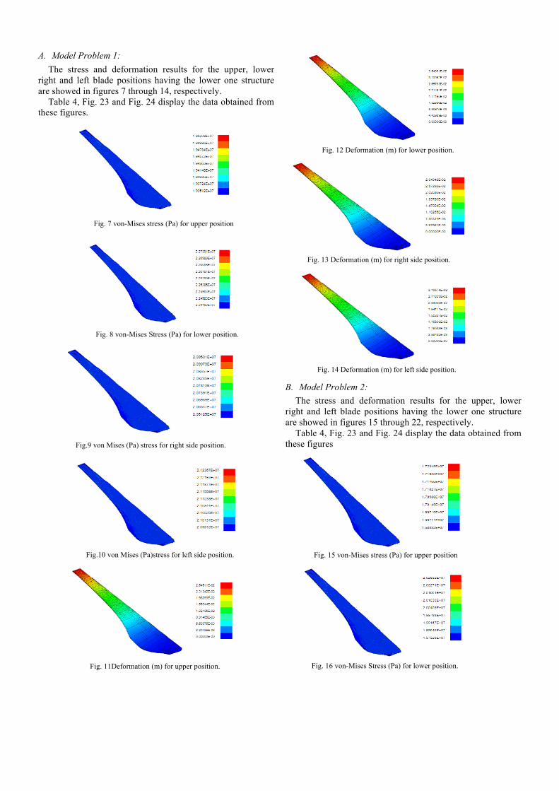
A. Model Problem 1: The stress and deformation results for the upper, lower
right and left blade positions having the lower one structure are showed in figures 7 through 14, respectively.
Table 4, Fig. 23 and Fig. 24 display the data obtained from these figures.
B. Model Problem 2: The stress and deformation results for the upper, lower
right and left blade positions having the lower one structure are showed in figures 15 through 22, respectively.
Table 4, Fig. 23 and Fig. 24 display the data obtained from these figures
Fig. 7 von-Mises stress (Pa) for upper position
Fig. 8 von-Mises Stress (Pa) for lower position.
Fig.9 von Mises (Pa) stress for right side position.
Fig.10 von Mises (Pa)stress for left side position.
Fig. 11Deformation (m) for upper position.
Fig. 12 Deformation (m) for lower position.
Fig. 13 Deformation (m) for right side position.
Fig. 15 von-Mises stress (Pa) for upper position
Fig. 16 von-Mises Stress (Pa) for lower position.
Fig. 14 Deformation (m) for left side position.

TABLE 4 NUMERICAL ANALYSIS FOR DIFFERENT BLADE MATERIALS
Structure Upper Lower Right Side
Left Side
Model 1 10%
tailing
Stress (MPa) 20.04 24.54 22.16 22.65
Deformation (mm) 29.44 38.52 30.95 31.71
Model 2
5% tailing & leading
Stress (MPa) 17.24 20.29 19.36 19.64
Deformation (mm) 21.49 30.57 23.71 24.52
Fig. 17 von Mises (Pa) stress for right side position.
Fig.18 von Mises (Pa)stress for left side position.
Fig. 19 Deformation (m) for upper position.
Fig. 20 Deformation (m) for lower position.
Fig. 21 Deformation (m) for right side position.
Fig. 22 Deformation (m) for left side position.
Fig. 23 Von Mises (Pa) stress for composite blades two models.
Fig. 24 Deformation (mm) for composite blades two models.
VI- CONCLUSION A methodology is presented to optimize a laminated
HAWT blades fabricated from composite materials. Two structures’ models have been manipulated in that methodology; the first has 10% tailing edge spar structure and the other has 5% at both tailing and leading edge spars. Throughout that study, following conclusions could be withdrawn:- • The optimum number of layers in the first model is
found to be 8 layers with the following structure (from the outer layer to the inner one):
• Fiber volume fractions are: 0.7, 0.64, 0.57 and 0.55, respectively.
• Stacking sequence of the fiber orientations are: [+8/ -19/+41/ +36]s, respectively.
• Layers’ thicknesses are: 12.73, 11.25, 9.30 and 8.21 mm, respectively.
• The optimum number of layers in the second model is
10 layers with the following structure (from the outer layer to the inner one):
• Fiber volume fractions are: 0.7, 0.68, 0.62, 0.57 and 0.54, respectively.
• Stacking sequence of the fiber orientations are: [+12/ -27/+39/-42/+45]s, respectively.
• Layers’ thicknesses are: 11.16, 9.29, 8.17, 7.16 and 5.71 mm, respectively.
The numerical models built in this work have strengthened the idea of manufacturing HAWT blade from composite materials. The second model shows a better stress and deformation (20.29 MPa and 30.57 mm) compared to the first one (24.54 MPa and 38.52 mm).
REFERENCES [1] C. W. Kensche, “Fatigue of composites for wind turbines”, Int. Journal
of Fatigue, Vol. 28, Issue 10, pp. 1363-1374, Oct. 2006. [2] E. Hau, Wind Turbines, 2nd ed., Germany: Springer- Verlag, 2006. [3] U. Hütter and A. Armbrust, “Betriebserfahrungen mit einer
Windkraftanlage von 100 kW der StudiengesellschaftWindkraft”, Brennstoff-Wärme-Kraft,Vol. 16, No. 7, 1964.
[4] A. Maheri, S. Noroozi, and J. Vinney, “Application of combined analytical/FEA coupled aero-structure simulation in design of wind turbine adaptive blades”, Renewable Energy, Vol. 32, Issue 12, pp. 2011-2018, Oct. 2007.
[5] S. Venkataraman, and R. Haftka, “Optimization of composite panels”, a review. In: Proceedings of the 14th annual technical conference of the American society of composites, pp. 479-488, Sept. 1999.
[6] J. Holland, Adaptation in natural and artificial systems, Ann Arbor: University of Michigan Press; 1975.
[7] G. Soremekun, Z. Gürdal, R. T. Haftka, and L. T. Watson, "Composite laminate design optimization by genetic algorithm with generalized elitist selection", Computer Structure, Vol. 79, pp. 131 – 143, Jan. 2001.
[8] J. H. Park, J. H. Hwang, C. S. Lee and W. Hwang, "Stacking sequence design of composite laminates for maximum strength using genetic algorithms", Composite Structure, Vol. 52, PP 217 – 231, May 2001.
[9] Chamis, C.C., "Simplified composite micromechanics equations for strength, fracture toughness, impact resistance and environmental effects", NASA Tech. Memo 83696, Lewis Research Center, Jan. 1984.
[10] K. Deb, "A fast and elitist multi-objective genetic algorithm NSGA-II", IEEE Trans Evolution Comp., Vol. 6, Issue 2, PP 182 – 196, Apr. 2002.
[11] J. L. Pelletier and S. S. Vel, “Multi-objective optimization of fiber reinforced composite laminates for strength, stiffness and minimal mass”, Computers and Structures, Vol. 84, PP. 2065–2080, Sept. 2006.
[12] J. N. Reddy, Mechanics of laminated composite plates and shells theory and analysis, CRC Press, 2004.
[13] S. W. Tsai and E. M. Wu, "A general theory of strength in anisotropic materials", Composite Material Journal, Vol. 5, PP 58 – 80, Jan. 1971.
[14] M. Walker, and R. E. Smith, "A technique for the multi-objective optimization of laminated composite structures using genetic algorithms and finite element analysis", Composite Structure, Vol. 62, PP 123 – 128, Oct. 2003.
[15] L. Costa, L. Fernandes, I. Figueiredo, J. Júdice, R. Leal, P. Oliveira, "Multiple- and single-objective approaches to laminate optimization with genetic algorithms", Structure Multidisc Optimization, Vol. 27, PP 55 – 65, May 2004.
[16] D. E. Goldberg, Genetic algorithms in search, optimization, and machine learning, Addison Wesley, 1989.
[17] K. Deb, "An efficient constraint handling method for genetic algorithms", Computer Meth, Applied Mechanics Eng., Vol. 186, PP 311 – 328, Jun. 2000.
[18] K. Deb, Multi-objective optimization using evolutionary algorithms, John Wiley and Sons Ltd., 2001.
[19] M. Puterbaugh and A. Beyene, “Parametric dependence of a morphing wind turbine blade on material elasticity”, Energy Journal, Vol. 36, pp. 466-474, Nov. 2011.
[20] T. Burton, D. Sharpe, N. Jenkins and E. Bossanyi, Wind Energy Handbook, John Wiley &Sons Ltd., 2001.
[21] Eurocode 1, “Basis of design and actions on structures – Part 2.4: Actions on structures –Wind actions”, 1997.
[22] J. Aboudi, "Mechanics of composite materials: a unified micromechanical approach", Elsevier, 1991.
[23] D. B. Miracle and S. L. Donaldson, ASM Handbook Vol. 21: Composite, ASM, 2001
[24] J.G. Schepers, "Final Report of IEA Annex XVIII: Enhanced Field Rotor Aerodynamics Database", Technical Report ECN-C-02-016, Energy research Centre of the Netherlans, 2002.