
Optimizing Transmission Lengths for Limited Feedback with ...
13
1 Optimizing Transmission Lengths for Limited Feedback with Non-Binary LDPC Examples Kasra Vakilinia, Sudarsan V. S. Ranganathan, Dariush Divsalar*, and Richard D. Wesel Department of Electrical Engineering, University of California, Los Angeles, Los Angeles, California 90095 *Jet Propulsion Laboratory, California Institute of Technology, Pasadena, California 91109 Abstract—This paper presents a general approach for optimiz- ing the number of symbols in increments (packets of incremental redundancy) in a feedback communication system with a limited number of increments. This approach is based on a tight normal approximation on the rate for successful decoding. Applying this approach to a variety of feedback systems using non-binary (NB) low-density parity-check (LDPC) codes shows that greater than 90% of capacity can be achieved with average blocklengths fewer than 500 transmitted bits. One result is that the performance with ten increments closely approaches the performance with an infinite number of increments. The paper focuses on binary- input additive-white Gaussian noise (BI-AWGN) channels but also demonstrates that the normal approximation works well on examples of fading channels as well as high-SNR AWGN channels that require larger QAM constellations. The paper explores both variable-length feedback codes with termination (VLFT) and the more practical variable length feedback (VLF) codes without termination that require no assumption of noiseless transmitter confirmation. For VLF we consider both a two-phase scheme and CRC-based scheme. I. I NTRODUCTION The classical results from [1] show that feedback does not increase the capacity of discrete memoryless channels. However, Polyanskiy et al. [2] and Chen et al. [3] show that capacity can be approached in a smaller number of channel uses using feedback. Polyanskiy et al. [2] introduce random- coding lower bounds for variable-length feedback coding with termination (VLFT) and without termination (VLF), which approach capacity with average blocklengths of hundreds of bits. A communication system without feedback, on the other hand, requires thousands of bits to closely approach capacity [4]. This paper demonstrates practical systems using non- binary low-density parity-check (NB-LDPC) codes that match or exceed the lower bounds of [2]. Most of the analysis in this paper is not exclusive for NB-LDPC codes, but NB-LDPC codes are used for demonstration because they perform well in the short-blocklength regime (150 to 600 bits) that is of interest. In VLFT analysis of [2], the receiver provides full noiseless feedback to the transmitter. The transmitter sends additional incremental bits until it knows the receiver has decoded the This material is based upon work supported by the National Science Foundation under Grant Numbers 1162501 and 1161822. Any opinions, findings, and conclusions or recommendations expressed in this material are those of the author(s) and do not necessarily reflect the views of the National Science Foundation. This research was carried out in part at the Jet Propulsion Laboratory, California Institute of Technology, under a contract with NASA, and JPL Task Plan 82-17473. message correctly, resulting in zero probability of error. The “T” in VLFT stands for termination and corresponds to a noiseless transmitter confirmation (NTC) bit that the transmit- ter uses to terminate the transmission. The NTC is transmitted through a channel different from the main communication channel. In contrast, VLF (without the “T”) does not have the advantage of an NTC. All VLF forward transmissions go over the same noisy channel. Thus, there is always a nonzero probability of undetected error in VLF. VLF and VLFT are examples of hybrid automatic repeat request (HARQ) schemes. Prior to Polyanskiy et al. [2] and Chen et al. [3], HARQ feedback schemes had been studied in great detail in many papers including for example [5]–[10]. These papers provide an overview of HARQ, discuss how error correcting codes can be combined with ARQ and demonstrate applications of HARQ. In particular, [10] shows that hybrid ARQ is especially useful in point-to-point scenarios. The coding schemes that are most commonly explored in HARQ systems [11]–[13] are based on convolutional codes (CCs) or a concatenation of turbo and block parity-check codes, where the Bahl-Cocke-Jelinek-Raviv (BCJR) algorithm is used to determine which bit is unreliable and needs to be transmitted in the subsequent transmissions. These works use a genie (equivalent to NTC in VLFT) to terminate transmissions. In order to remove the genie and realize a more practi- cal system (equivalent to VLF) [7], [9], [14]–[17] consider reliability-based HARQ using convolutional codes where the transmission terminates when the probability of having a correctly decoded message is high enough. For example, in [9] the reliability metric is based on the average magnitude of the log-likelihood ratios of the source symbols. In [18], [19], Soljanin et al. study VLFT HARQ using rate- compatible binary LDPC codes. They use maximum likelihood (ML) decoding analysis to determine the size of incremental transmissions in case of decoding failure. In [20], [21] Soljanin et al. extend their analysis to time-varying binary erasure channels. Some other high-throughput ARQ schemes use rateless spinal codes as in [22], [23], where hash functions are used for the subsequent coded symbols. In [24], Romero uses cyclic redundancy check (CRC) codes to study the performance of spinal codes in VLF setting. Use of polar codes with HARQ is also studied in [25], [26]. These works present polar- code-based HARQ schemes over binary-input additive white Gaussian noise (BI-AWGN) and Rayleigh fading channels using Chase combining.
Transcript of Optimizing Transmission Lengths for Limited Feedback with ...

1
Optimizing Transmission Lengths for LimitedFeedback with Non-Binary LDPC Examples
Kasra Vakilinia, Sudarsan V. S. Ranganathan, Dariush Divsalar*, and Richard D. WeselDepartment of Electrical Engineering, University of California, Los Angeles, Los Angeles, California 90095
*Jet Propulsion Laboratory, California Institute of Technology, Pasadena, California 91109
Abstract—This paper presents a general approach for optimiz-ing the number of symbols in increments (packets of incrementalredundancy) in a feedback communication system with a limitednumber of increments. This approach is based on a tight normalapproximation on the rate for successful decoding. Applying thisapproach to a variety of feedback systems using non-binary (NB)low-density parity-check (LDPC) codes shows that greater than90% of capacity can be achieved with average blocklengths fewerthan 500 transmitted bits. One result is that the performancewith ten increments closely approaches the performance withan infinite number of increments. The paper focuses on binary-input additive-white Gaussian noise (BI-AWGN) channels butalso demonstrates that the normal approximation works well onexamples of fading channels as well as high-SNR AWGN channelsthat require larger QAM constellations. The paper explores bothvariable-length feedback codes with termination (VLFT) and themore practical variable length feedback (VLF) codes withouttermination that require no assumption of noiseless transmitterconfirmation. For VLF we consider both a two-phase scheme andCRC-based scheme.
I. INTRODUCTION
The classical results from [1] show that feedback doesnot increase the capacity of discrete memoryless channels.However, Polyanskiy et al. [2] and Chen et al. [3] show thatcapacity can be approached in a smaller number of channeluses using feedback. Polyanskiy et al. [2] introduce random-coding lower bounds for variable-length feedback coding withtermination (VLFT) and without termination (VLF), whichapproach capacity with average blocklengths of hundreds ofbits. A communication system without feedback, on the otherhand, requires thousands of bits to closely approach capacity[4]. This paper demonstrates practical systems using non-binary low-density parity-check (NB-LDPC) codes that matchor exceed the lower bounds of [2]. Most of the analysis inthis paper is not exclusive for NB-LDPC codes, but NB-LDPCcodes are used for demonstration because they perform wellin the short-blocklength regime (150 to 600 bits) that is ofinterest.
In VLFT analysis of [2], the receiver provides full noiselessfeedback to the transmitter. The transmitter sends additionalincremental bits until it knows the receiver has decoded the
This material is based upon work supported by the National ScienceFoundation under Grant Numbers 1162501 and 1161822. Any opinions,findings, and conclusions or recommendations expressed in this material arethose of the author(s) and do not necessarily reflect the views of the NationalScience Foundation. This research was carried out in part at the Jet PropulsionLaboratory, California Institute of Technology, under a contract with NASA,and JPL Task Plan 82-17473.
message correctly, resulting in zero probability of error. The“T” in VLFT stands for termination and corresponds to anoiseless transmitter confirmation (NTC) bit that the transmit-ter uses to terminate the transmission. The NTC is transmittedthrough a channel different from the main communicationchannel. In contrast, VLF (without the “T”) does not havethe advantage of an NTC. All VLF forward transmissions goover the same noisy channel. Thus, there is always a nonzeroprobability of undetected error in VLF.
VLF and VLFT are examples of hybrid automatic repeatrequest (HARQ) schemes. Prior to Polyanskiy et al. [2] andChen et al. [3], HARQ feedback schemes had been studiedin great detail in many papers including for example [5]–[10].These papers provide an overview of HARQ, discuss how errorcorrecting codes can be combined with ARQ and demonstrateapplications of HARQ. In particular, [10] shows that hybridARQ is especially useful in point-to-point scenarios. Thecoding schemes that are most commonly explored in HARQsystems [11]–[13] are based on convolutional codes (CCs) ora concatenation of turbo and block parity-check codes, wherethe Bahl-Cocke-Jelinek-Raviv (BCJR) algorithm is used todetermine which bit is unreliable and needs to be transmittedin the subsequent transmissions. These works use a genie(equivalent to NTC in VLFT) to terminate transmissions.
In order to remove the genie and realize a more practi-cal system (equivalent to VLF) [7], [9], [14]–[17] considerreliability-based HARQ using convolutional codes where thetransmission terminates when the probability of having acorrectly decoded message is high enough. For example, in[9] the reliability metric is based on the average magnitude ofthe log-likelihood ratios of the source symbols.
In [18], [19], Soljanin et al. study VLFT HARQ using rate-compatible binary LDPC codes. They use maximum likelihood(ML) decoding analysis to determine the size of incrementaltransmissions in case of decoding failure. In [20], [21] Soljaninet al. extend their analysis to time-varying binary erasurechannels.
Some other high-throughput ARQ schemes use ratelessspinal codes as in [22], [23], where hash functions are usedfor the subsequent coded symbols. In [24], Romero uses cyclicredundancy check (CRC) codes to study the performance ofspinal codes in VLF setting. Use of polar codes with HARQis also studied in [25], [26]. These works present polar-code-based HARQ schemes over binary-input additive whiteGaussian noise (BI-AWGN) and Rayleigh fading channelsusing Chase combining.

2
The closest work to the analysis presented here is byPfletschinger et al. in [27] which uses rate-adaptive, non-binary LDPC codes in a HARQ scheme over Rayleigh fadingchannel in the VLFT setting. They present two algorithms thatuse channel statistics and mutual information to optimize theblocklengths for each transmission to maximize the through-put. Based on channel state information at transmitter, the coderates, modulations, and maximum number of retransmissionsare all optimized prior to initial transmission.
Chen et al. [3], [28] and Williamson et al. [29] analyzed aVLFT scheme based on rate-compatible sphere-packing withan ML decoder (RCSP-ML) and simulated a VLFT schemeusing convolutional codes. The approximation based on RCSP-ML extends sphere-packing analysis from a single fixed-lengthcode to a family of rate-compatible codes, where each code inthe family achieves perfect packing and is decoded by an MLdecoder. For the 2-dB BI-AWGN channel with feedback, theconvolutional codes achieve about 95% of the idealized RCSP-ML throughput (RRCSP ) for average blocklengths up to 50bits. In [30], Williamson et al. also analyzed VLF systems forsimilar blocklengths of up to 100 bits.
However, for average blocklengths of 100 bits and larger,the throughput of the convolutional code decreases becausethe frame-error rate performance of the convolutional codedegrades as the length of code increases. As Chen et al.mention in [28], coding schemes with throughput performanceclose to RCSP-ML in VLFT still remain to be identified forexpected latencies (average blocklengths) of 200 to 600 bits.This blocklength regime is important because it is still shortenough that feedback provides a real advantage but also longenough that the system can be practical.
The primary purposes of this paper are to show how tooptimize the lengths of incremental transmissions and todemonstrate that NB-LDPC codes with optimized incrementaltransmissions can achieve throughputs close to theoreticallimits for expected latencies of 150 to 500 bits in the VLFTand VLF settings. Most of the following analysis is appli-cable to any coding scheme, but we use NB-LDPC codesto demonstrate the possible performance motivated by [31],which shows that NB-LDPC codes without feedback, performwell in this short-blocklength regime.
In our precursor conference papers [32], [33] we prelimi-narily analyzed the performance of NB-LDPC codes in VLFTfor a BI-AWGN channel with an SNR of 2 dB with anunlimited number of transmissions and with the number oftransmissions m fixed to be five. We also considered two-phaseVLF system with m = 5. In VLFT, the non-binary LDPCcodes of [32] attain 91% to 93% of the predicted RCSP-MLthroughput for average blocklengths of 150 to 450 bits. In aVLF scheme of [33] incorporating a confirmation phase aftereach communication phase (hence called “two-phase”), 92%of capacity is achieved in less than 500 bits with a maximumof five transmissions.
In this paper, we extend the results of the previous papersto consider a broader range of m, the number of possibletransmissions. We also introduce a new VLF system thatuses a stopping criterion that incorporates a cyclic redundancycheck (CRC). This new system achieves better throughput
performance than the schemes of [32], [33] for the exampleBI-AWGN channel with an SNR of 2 dB in the blocklengthregime of 150 to 600 bits. For this channel, the CRC-basedVLF scheme achieves about 94% of the capacity with anunlimited number m of transmissions and about 92% of thecapacity with m = 10.
We also extend these results to a higher-SNR (8 dB)channel and use a larger 16 quadrature amplitude modulation(QAM) constellation. The capacity of the 8 dB 16-QAMAWGN channel is 2.68 bits per symbol. The VLF-with-CRCsystem with an unlimited number of transmissions achievesa throughput of 2.37 bits per symbol with a frame errorprobability of less than 10−3. This throughput correspondsto 88% of the capacity in the blocklength regime of about40 16-QAM symbols. Furthermore, we extend the results toa SNR-5dB BI-AWGN fading channel with the channel stateinformation (CSI) available at the receiver. The capacity ofthis channel is 0.67 bits. The VLF-with-CRC system withan unlimited number of transmissions achieves a throughputof 0.60 with a frame error probability of less than 10−3.This throughput corresponds to 90% of the capacity in theblocklength regime of about 140 bits.
The rest of the paper proceeds as follows: Section IIprovides an overview of the VLFT system with NB-LDPCcodes and the reciprocal-Gaussian approximation for theprobability mass function of the cumulative blocklengths.Section III presents the sequential differential optimizationalgorithm (SDO) for optimizing the size of each incrementaltransmission in VLFT. Section IV presents a VLF system withCRC and analyzes this system with an unlimited number oftransmissions. Section V extends the results of Section IV tothe system with a limited number of transmissions. SectionVI gives an overview of the two-phase VLF scheme and usesSDO to optimize the cumulative blocklength at each decodingattempt. Section VII compares the throughput and the expectedlatency of NB-LDPC and convolutional codes in VLFT andVLF settings. Section VIII concludes the paper.
II. VLFT WITH NON-BINARY LDPC CODES
Feedback can facilitate capacity-approaching performanceat significantly shorter average blocklengths than systemswithout feedback. This improvement is made possible bycapitalizing on favorable noise realizations to decode early.In case of a bad channel realization, the communication rateis lowered by transmitting additional information until theattempted rate matches the instantaneous rate the channelsupports.
In this paper, building on our precursor conference pa-pers [32], [33], we use high-rate protograph-based NB-LDPCcodes for the initial transmission. See [31] for a discussionof protograph-based LDPC design. These short-blocklengthcodes are irregular, having mostly degree-2 and a few degree-1 variable nodes. Refer to [32] for more discussion on thespecification of the codes.
For most of the analysis, the operating SNR in this paperis 2 dB, similar to the work of [28], [32], [33]. However,to emphasize the generality of the approach in this paper,

3
Section II-C shows results for higher-SNR AWGN and fadingchannels.
It is necessary that the initial transmission has a ratehigher than the capacity to take advantage of good channelrealizations. The coding rate is lowered until decoding issuccessful. For example for SNR-2dB BI-AWGN channel, theinitial code can have a rate of 0.75 to 0.8 while the capacityof the channel is 0.685.
We will consider feedback systems that transmit incrementalredundancy one bit at a time and also systems that transmitincremental redundancy in multiple-bit increments. For sys-tems that use multiple-bit increments, a practical system maylimit the maximum number m of increments. In the contextof a specified m, this paper optimizes the lengths of the mpossible increments to maximize throughput.
Section II-A provides a detailed description of how wegenerate each bit of incremental redundancy for the NB-LDPCcodes that we use. Then, Section II-B shows that in thecontext of this incremental redundancy, the coding rate thatfirst produces successful decoding is closely approximated bya normal distribution. Knowing a distribution that describesthe coding rate of the first successful decoding facilitatesoptimization of the lengths of multiple-bit increments, asdescribed in Section III.
A. Creating a bit for incremental transmission
In [32], Vakilinia et al. use NB-LDPC codes in a VLFTsystem with 1-bit increments. After the initial transmission, thetransmitter sends one bit at a time until the decoder decodescorrectly.
Traditionally, rate-compatible codes are designed by startingwith a low-rate mother code and increasing the rate bypuncturing the code. The proposed NB-LDPC coding schemein [32] does not explicitly involve puncturing. Rather, thedesign starts with a short, high-rate NB-LDPC code for whichall symbols are transmitted in the initial transmission. Eachsubsequent transmission is a single bit carefully selected tohelp the decoder as much as possible given its current decodingstate. The rate is gradually lowered by sending these additionalbits, each of which is a function of selected bits in the binaryrepresentation of the non-binary symbols.
A rate-KN NB-LDPC code over GF (2m) used in a binarycommunication link encodes an information sequence of sizeKm bits into a sequence of size Nm bits. In order to use anNB-LDPC code with the primitive element α over binary-inputchannels, each GF (2m) = {0, α0, α1, ..., α(2m−2)} symbol isconverted to m bits. For example, consider GF (23) with theprimitive element of α. Table I shows how each element ofGF (23) can be uniquely represented in 3 bits (g3, g2, g1).
TABLE I: Binary representation of GF (8) elements
αi 0 1 α α2 α3 α4 α5 α6
Poly. 0 1 α α2 α+1 α2+α α2+α+1 α2+1g3g2g1 000 001 010 100 011 110 111 101
The rate-KN non-binary LDPC codes proposed here ini-tially encode a sequence of Km bits (K GF (2m) symbols)
into a codeword of length Nm bits. Through incrementalredundancy, the rate is lowered from Km
Nm to KmNm+b where
b is number of additional incremental bits. Each additionalbit is created by an XOR (⊕) combination (summation inGF (2)) of bits in the binary representation of one GF (2m)symbol. For each variable node, the receiver computes thereliability of each of the 2m−1 possible combinations of thebits in the binary representation is computed. For example, inGF (23) the reliabilities of the seven possible combinationsg1, g2, g3, g1⊕ g2, g2⊕ g3, g1⊕ g3, and g1⊕ g2⊕ g3 are com-puted for each variable node. Finally, the single combinationbit that has the least reliability (e.g. considering all sevencombinations for all variable nodes and choosing the least-reliable combination for a single variable node) is requestedfrom the transmitter.
This is a form of active feedback in which relatively exten-sive feedback tells the transmitter what to transmit in contrastto non-active feedback in which a single bit of feedbackindicates whether to transmit. This is a generalization of theideas of active hypothesis testing [34]. In [32] Vakilinia et al.compared the performance of a non-active feedback systemand the active feedback system discussed earlier for NB-LDPCcodes and showed significantly better performance with theactive feedback system. The active feedback used in [32] tellsthe transmitter which bit combination to be transmitted next.This active feedback scheme does not require the receiver totransmit back the entire message, contrary to the analysis of[2]. In the non-active feedback scheme of [32] the additionalbits are selected at random.
This paper considers both active and non-active feedback.The non-active feedback in this paper corresponds to sendingthe XOR of all bits representing one of the variable nodes ofthe original rate-k/N0 NB-LDPC code. This predeterminednon-active feedback system performs close to the system withactive feedback since the active feedback of [32] usually asksfor the XOR of all bits for the subsequent transmissions. Thefigures and results in this paper indicate whether active ornon-active feedback scheme was used to generate them.
The input frame consisting of K GF (2m) informationsymbols is initially encoded by the rate-KN NB-LDPC encoderinto a sequence of length N GF (2m) symbols. These GF (2m)symbols are converted using their binary representations tobits. The Nm bits are modulated using binary phase shiftkeying (BPSK) and transmitted over an AWGN channel.The additive noise is modeled as an independent, zero-meanGaussian random sequence with variance σ2. As in [28], SNRis calculated as 1
σ2 , the ratio of the transmission power to thenoise variance.
B. Gaussian and reciprocal-Gaussian Approximations
Consider a stream of incremental redundancy as describedin Section II-A arriving one bit at a time at the receiver (afteran initial transmission of a high-rate NB-LDPC code). We areinterested in the statistical behavior of the random variabledescribing the blocklength of the first successful decoding andthe corresponding random variable describing the coding rateof that first successful decoding.

4
120 130 140 150 160 170 180 190 200 210 2200
0.01
0.02
0.03
0.04
Blocklength (NS)
Pro
babili
ty D
ensity F
unction
p.d.f of blocklength until the decoder converges to the correct codeword
VLFT Simulation ActiveInv−Gaussian Approx.
Fig. 1: Empirical probability mass function (p.m.f.) corre-sponding to the blocklength required for successful decodingfor the first time in VLFT using GF (256) NB-LDPC codeover SNR-2dB AWGN channel. Also shown is the reciprocal-Gaussian approximation of (3) with µS = 0.6374 and σS =0.0579. Smallest blocklength is N0 = 120 bits with k = 96information bits so that the initial rate is R0 = k
N0= 0.8.
Rate (RS)
Pro
bab
ility
De
nsity F
un
ction
p.d.f. of rate until the decoder converges to the correct codeword
0.4 0.45 0.5 0.55 0.6 0.65 0.7 0.75 0.80
2
4
6
8
VLFT Simulation Active Gaussian Approx.
Fig. 2: Empirical p.m.f. corresponding to RS = kNS
computedfrom Fig. 1 and Gaussian approximation of (1) with µS =0.6374 and σS = 0.0579.
0.4 0.45 0.5 0.55 0.6 0.65 0.7 0.75 0.80
0.2
0.4
0.6
0.8
1
Rate (RS)
Co
mp
lem
en
tary
Cu
mu
lative
Dis
trib
utio
n F
un
ctio
n
VLFT Simulation Active Gaussian Approximation
Fig. 3: Empirical c.c.d.f. and the approximation on the tail of anormal distribution (Q-function) corresponding to the shadedarea of Fig. 2.
For the system of [32], the “VLFT simulation active” plotin Fig. 1 shows the empirical p.m.f. of the blocklength offirst successful decoding. The total blocklength NS includesthe initial block and all incremental transmissions, (with activefeedback) required for receiver to decode the NB-LDPC code-word correctly for the first time. The “VLFT simulation active”plot in Fig. 2 shows the empirical p.m.f. of the instantaneousrate
(RS = k
NS
)at which decoding is successful for the first
time. Fig. 2 shows that RS is well-approximated by a normaldistribution
fRS (r) =1√2πσ2
S
e− (r−µS)
2
2σ2S (1)
with mean µS = E(RS) and variance σ2S = Var(RS).
The intuition behind these approximations is consistent withthe “normal approximation” of the accumulated informationdensity due to the law of large numbers (LLN) in [4].
To maximize throughput, the initial code-rate of the NB-LDPC code is chosen so that almost no codeword is success-fully decoded in the initial transmission. Thus, the empiricalprobability mass function (p.m.f.) of the number of additionalincrements required to decode correctly does not have a spikeat zero.
Fig. 3 shows the complementary cumulative distributionfunction (c.c.d.f.) for the distribution of RS and the Gaussianapproximation of Fig. 2. Fig. 3 confirms that the distributionof RS is well approximated by a Gaussian distribution. Asdiscussed later, the empirical c.c.d.f is used to show that theGaussian approximation is valid for a variety of AWGN chan-nels including the high SNR ones using larger constellationsand also for fading channels. The “VLFT simulation active”plot in Fig. 3 shows the empirical c.c.d.f. of the instantaneousrate
(RS = k
NS
)at which decoding is successful for SNR-2dB
BI-AWGN of [33]. This c.c.d.f. plot shows the cumulativeprobability that the channel supports a rate higher than therate on the x axis. This higher rate means that the decodinghas been successful with a lower number of transmitted bits.The c.c.d.f. plot corresponds to the shaded area of Fig. 2. The“Gaussian Approximation” plot of Fig. 3 corresponds to thetail probability of the standard normal distribution of Fig. 2.
The parameters µS and σ2S in (1) for a particular code
need to be determined through simulation and curve fitting.Having the p.m.f. of the NS , the curve fitting process involvescalculating the p.m.f. and c.c.d.f. of RS and solving a linearregression problem to obtain µS and σS . Note that µS isnot the expected throughput but rather the average of theinstantaneous rates supported by the channel.
The cumulative distribution function (c.d.f.) of NS isFNS (n) = P (NS ≤ n), and we have
FNS (n) = P(k
RS≤ n)= P
(RS ≥
k
n
)= 1− FRS (
k
n). (2)
Taking the derivative of FNS using the Gaussian approxi-mation of FRS produces the following “reciprocal-Gaussian”approximation for p.d.f. of NS :
fNS (n) =k
n2√2πσ2
S
e
−(kn−µS)22σ2S . (3)
This p.d.f as shown in Fig. 1 closely approximates theempirical distribution of NS . For N1 < N2, the probabilityof the decoding attempt being successful at blocklength N2
5
1.8 2 2.2 2.4 2.6 2.8 3 3.20
0.2
0.4
0.6
0.8
1
Rate (RS)
Com
ple
menta
ry C
um
ula
tive D
istr
ibution F
unction
VLFT Simulation Active Gaussian Approximation
Fig. 4: Empirical c.c.d.f. and the approximation on the tail ofa normal distribution with µS = 2.63 and σS = 0.19 of theinstantaneous rate
(RS = k
NS
)at which decoding is successful
for SNR-8dB 16-QAM AWGN channel.
but not at N1 using this approximation is∫ N2
N1
fNS (n)dn =
∫ N2
N1
k
n2√
2πσ2S
e
−(kn−µS)2
2σ2S dn (4)
= Q
(kN2− µSσS
)−Q
(kN1− µSσS
). (5)
The increase in blocklength from N1 to N2 reduces the ratefrom k
N1to k
N2. Note that (5) gives the probability that the
channel supports rate kN2
while not supporting the higher ratekN1
. The Q functions in (5) are due to the normally-distributedhighest-rate-of-successful-decoding (RS) at k
N1and k
N2.
C. General Applicability of the Normal Approximation
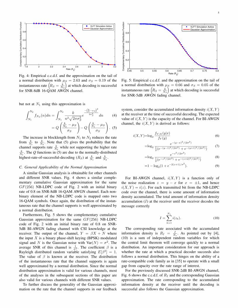
A similar Gaussian analysis is obtainable for other channelsand different SNR values. Fig. 4 shows a similar comple-mentary cumulative Gaussian approximation for the sameGF (256) NB-LDPC code of Fig. 2 with an initial binaryrate of 0.8 on SNR-8dB 16-QAM AWGN channel. Each non-binary element of the NB-LDPC code is mapped onto two16-QAM symbols. Once again, the distribution of the instan-taneous rate that the channel supports is well approximated bya normal distribution.
Furthermore, Fig. 5 shows the complementary cumulativeGaussian approximation for the same GF (256) NB-LDPCcode of Fig. 2 with an initial binary rate of 0.8 on SNR-5dB BI-AWGN fading channel with CSI knowledge at thereceiver. The output of the channel, Y = βX + N wherethe input X is a binary phase-shift keying (BPSK) modulatedsignal and N is the Gaussian noise with Var(N) = σ2. Theaverage SNR of this channel is 1
σ2 . The coefficient β is aRayleigh distributed random variable satisfying E[β2] = 1.The value of β is known at the receiver. The distributionof the instantaneous rate that the channel supports is againwell approximated by a normal distribution. Since the normaldistribution approximation is valid for various channels, mostof the analyses in the subsequent sections of this paper arealso valid for various channels with different SNR values.
To further discuss the generality of the Gaussian approxi-mation on the rate that the channel supports in our feedback
0.45 0.5 0.55 0.6 0.65 0.7 0.75 0.80
0.2
0.4
0.6
0.8
1
Rate (RS)
Co
mp
lem
en
tary
Cu
mu
lative
Dis
trib
utio
n F
un
ctio
n
VLFT Simulation Active Gaussian Approximation
Fig. 5: Empirical c.c.d.f. and the approximation on the tail ofa normal distribution with µS = 0.66 and σS = 0.05 of theinstantaneous rate
(RS = k
NS
)at which decoding is successful
for SNR-5dB AWGN fading channel.
system, consider the accumulated information density i(X,Y )at the receiver at the time of successful decoding. The expectedvalue of i(X,Y ) is the capacity of the channel. For BI-AWGNchannel, the i(X,Y ) is derived as follows:
i(X,Y )=log2fY |X(y|x)fY (y)
(6)
=log2e−(y−x)2/(2σ2)
12(e−(y−1)2/(2σ2) + e−(y+1)2/(2σ2))
(7)
=log2e−z
2/(2σ2)
12(e−z2/(2σ2) + e−(z+2)2/(2σ2))
(8)
=1− log2(1 + e−2(z+1)/σ2
). (9)
For BI-AWGN channel, i(X,Y ) is a function only ofthe noise realization z = y − x for x = ±1, and hencei(X,Y ) = i(z). For each transmitted bit from the NB-LDPCcode over the channel, there is some amount of informationdensity accumulated. The total amount of information densityaccumulation (I) at the receiver until the receiver decodes themessage correctly
I =
Ns∑k=1
i(zk). (10)
The corresponding rate associated with the accumulatedinformation density is RI = I
Ns. As pointed out by [4],
(10) is a sum of independent random variables for whichthe central limit theorem will converge quickly to a normaldistribution. An important consideration for our approach iswhether the rate at which a practical decoder succeeds alsofollows a normal distribution. This hinges on the ability of arate-compatible code family as in [35] to operate with a smallgap from capacity over the rate range of interest.
For the previously discussed SNR-2dB BI-AWGN channel,Fig. 6 shows the c.c.d.f. of RI and the corresponding Gaussianapproximation. The rate corresponding to the accumulatedinformation density at the receiver until the decoding issuccessful also follows the Gaussian approximation.

6
0.4 0.5 0.6 0.7 0.8 0.90
0.2
0.4
0.6
0.8
1
Rate (RI)
Com
ple
menta
ry C
um
ula
tive D
istr
ibution F
unction
VLFT Simulation
Gaussian Approximation
Fig. 6: Empirical c.c.d.f. and the approximation on the tail ofa normal distribution with µS = 0.64 and σS = 0.06 of theaverage accumulated information density
(RI =
INS
)at which
decoding is successful for SNR-2dB AWGN channel.
0.4 0.45 0.5 0.55 0.6 0.65 0.7 0.75 0.80.4
0.5
0.6
0.7
0.8
0.9
Rate at which decoding is successful
avera
ge info
rmation d
ensity a
t decodin
g
VLFT Simulation Ideal Decoder
Fig. 7: Average amount of the accumulated information den-sity for decoding correctly at a particular code rate for theGF(256) NB-LDPC of Fig. 1 code over SNR-2dB AWGNchannel.
Fig. 7 shows the average accumulated information densityfor decoding correctly at a particular code rate for the NB-LDPC code. This figure shows on average, how much moreinformation in number of bits the NB-LDPC code requires todecode the message correctly compared to the operating rate.The “ideal decoder” plot in Fig. 7 corresponds to the averageaccumulated information density being equal to the rate (theline of equality).
III. OPTIMIZING TRANSMISSION LENGTHS
Consider the scenario in which the number of increments(packets of incremental redundancy) associated with a code-word that can be accumulated at the receiver is limited tom. Using the p.d.f. of NS from (3) we find the optimalblocklengths {N1, N2, . . . , Nm} to maximize the throughput.The initial blocklength N1 satisfies N1 ≥ N0 where N0 is thesmallest possible blocklength (of the original NB-LDPC code).Each of the additional bits beyond N0 transmitted in the firsttransmission is the exclusive-or of all eight bits representingone of the variable nodes of the original rate-k/N0 GF(256)NB-LDPC code. The other transmissions use the scheme inSection II-A to generate the subsequent bits.
A. Throughput optimization through exhaustive search
An accumulation cycle (AC) is a set of m or fewertransmissions and decoding attempts ending when decodingis successful or when the mth decoding attempt fails. Ifdecoding is not successful after the mth decoding attempt,the accumulated transmissions are forgotten and the processstarts over with a new transmission of the first block of N1
symbols. From a strict optimality perspective, neglecting thesymbols from the previous failed AC is sub-optimal. However,the probability of an AC failure is sufficiently small thatthe performance degradation is negligible. Neglecting thesesymbols greatly simplifies analysis.
Define the throughput as RT = E[K]E[N ] , where E[N ] repre-
sents the expected number of channel uses in one AC andE[K] is the effective number of information bits transferredcorrectly over the channel in one AC.
The expression for E[N ] is
E[N ] = N1Q
(kN1− µSσS
)(11)
+
m∑i=2
Ni
[Q
(kNi− µSσS
)−Q
(k
Ni−1− µS
σS
)](12)
+Nm
[1−Q
( kNm− µSσS
)]. (13)
The right hand side of (11) shows the contribution toexpected blocklength from successful decoding on the first
attempt in the AC. Q(
kN1−µSσS
)is the probability of decoding
successfully with the initial block of N1. Similarly, the termsin (12) are the contributions to expected blocklength fromdecoding that is first successful at total blocklength Ni (atthe ith decoding attempt). Finally, the contribution to expectedblocklength from not being able to decode even at Nm is
1 − Q
(kNm−µSσS
)which is shown in (13). Even when the
decoding has not been successful at Nm, the channel has beenused for Nm channel symbols.
The expected number of successfully transferred informa-tion bits E[K] is
E[K] = kQ
( kNm− µSσS
), (14)
where Q(
kNm−µSσS
)is the probability of successful decoding
at some point in the AC. Note that E[K] depends only uponNm. In fact, for large values of Nm, E[K] ≈ k and thus notsensitive to the choice of Nm
Exhaustive search (ES) can be used to optimize{N1, N2, . . . , Nm} to maximize RT = E[K]
E[N ] . The order ofcomplexity for ES is O
((Nmax−N0+1
m
)), where Nmax is the
maximum allowable overall blocklength for an AC. SinceE[K] ≈ k, maximization of RT is equivalent to minimizationof E[N ].

7
B. Sequential differential optimization
Sequential differential optimization (SDO) is an extremelyeffective alternative to ES. Over a range of possible N1 values,SDO optimizes {N2, . . . , Nm} to minimize E[N ] for eachfixed value of N1 by setting derivatives to zero as follows:{
N2, . . . , Nm :∂E[N ]
∂Ni= 0, ∀i = 1, . . . ,m−1
}. (15)
For each i ∈ {2, . . . ,m}, the optimal value of Ni is foundby setting ∂E[N ]
∂Ni−1= 0, yielding a sequence of relatively simple
computations. In other words, we select the Ni that makes ourprevious choice of Ni−1 optimal in retrospect. For example tofind N2 we compute the derivative
∂E[N ]
∂N1= Q
(kN1− µSσS
)+(N1−N2)Q
′
(kN1− µSσS
)= 0 (16)
and solve for N2 as
N2 =
Q
(kN1−µSσS
)+N1Q
′(
kN1−µSσS
)Q′
(kN1−µSσS
) , (17)
where
Q′
(kNi− µSσS
)=
k
N2i σS
1√2πe
(kNi
−µS
)22σ2S . (18)
For i > 2, ∂E[N ]∂Ni−1
= 0 depends only on {Ni−2, Ni−1, Ni} asfollows:
∂E[N ]
∂Ni−1=Q
(k
Ni−1−µσ
)+(Ni−1−Ni)Q′
(k
Ni−1−µσ
)−Q
(k
Ni−2−µ
σ
).
Thus we can solve for Ni as
Ni =
Q
(k
Ni−1−µ
σ
)+Ni−1Q
′(
kNi−1
−µ
σ
)−Q(
kNi−2
−µ
σ
)Q′
(k
Ni−1−µ
σ
) . (19)
Actually, for each possible value of N1, SDO can be usedto produce an infinite sequence of Ni values that solve (15).Each such sequence is an optimal sequence of increments fora given density of retransmission points on the transmissionaxis. As N1 increases, the density decreases. Using SDO tocompute the optimal m points is equivalent to selecting themost dense SDO-optimal sequence that when truncated to mpoints results in the highest throughput.
C. Application to VLFT with m transmissions
Table II shows the optimized {N1, N2, . . . , Nm}, resultingthroughput RT , and expected blocklength λ = k/RT forvarious m. The values obtained by SDO are very close tothe values obtained by ES.
For m = 2, 5, 6, and 7, the optimized blocklengths for bothapproaches are the same. For m = 3 and 4 the blocklengthsdiffer only in the value of Nm (shown in bold) and onlyby one bit. This small difference in Nm causes a negligible
TABLE II: Optimized {N1, N2, . . . , Nm}, RT , and λ from ESand SDO for k = 96 bits for VLFT on a 2 dB SNR binary-inputAWGN channel using µS = 0.6374 and σS = 0.0579.
Alg. m {N1, N2, . . . , Nm} RT λ
ES, SDO 2 158 , 188 0.566 169.6ES 3 150, 167, 194 0.58638 163.71SDO 3 150, 167, 195 0.58635 163.72ES 4 146, 158, 172, 198 0.59709 160.77SDO 4 146, 158, 172, 197 0.59707 160.78ES, SDO 5 143, 153, 163, 176, 201 0.603 159.2ES, SDO 6 140, 149, 157, 166, 179, 204 0.608 157.9ES, SDO 7 139, 147, 154, 161, 170, 182, 206 0.611 157.1
2 4 6 8 10 12 14 16 18 200.5
0.52
0.54
0.56
0.58
0.6
0.62
0.64
VLFT RT for various values of m
m
RT
VLFT RT m=∞
VLFT RT for m=2,3,...,20
2 4 6 8 10 12 14 16 18 20150
160
170
180
190
VLFT λ for various values of m
m
λ
VLFT λ m=∞
VLFT λ for m=2,3,...,20
Fig. 8: Throughput (RT ) and the expected blocklength (λ)as a function of the number of transmissions m achieved bynon-binary LDPC codes in the VLFT setting for k = 96.
difference in the maximum throughput RT and minimumexpected blocklength λ = k
RT. Since the complexity of ES
is exponential in m, it is infeasible to obtain a globallyoptimal solution for m > 7; whereas SDO, with complexityO(Nmax − N0), can find a solution within seconds even forlarge m.
Fig. 8 shows the optimum RT and λ for various m usingSDO. The dashed lines show the maximum achievable RT andthe corresponding minimum achievable λ with an unlimited mas in [32]. As a function of m, RT quickly converges to them = ∞ asymptote and even for m ≈ 10 the throughputis close to the value achievable with an unlimited numberof increments. Correspondingly, the expected latency alsoconverges quickly and for m ≈ 10 the expected blocklength isclose to the minimum λ achievable by unlimited transmissionsof one bit at a time.

8
IV. VLF WITH CRC
In this section, instead of using NTC as a genie, cyclicredundancy check (CRC) codes are used as error-detectingcodes to detect whether there is an error in the decodedmessage. In systems incorporating CRCs, a certain number ofcheck bits, Lcrc, are computed and added to the informationmessage of length kinf.
At the receiver, the NB-LDPC decoder initially attempts todecode the received block. If decoding results in a codeword,the CRC check determines whether the check bits agree withthe data by computing the checksum from the first kinf bits ofthe received sequence and comparing this checksum with thelast Lcrc received bits. In order to achieve an undetected errorprobability of ε, the CRC code length Lcrc is chosen so thatthe overall probability of error resulting from the NB-LDPCand CRC codes combined is smaller than ε.
The transmitter terminates transmission when the receiversends feedback indicating that the decoded message passes theCRC check. If the message is correctly decoded, it passes theCRC and the transmitter moves on to the next message. Ifthe message is decoded incorrectly and the decoded messagefails to pass CRC, the transmitter sends more bits to increasereliability of the bits already transmitted. If the receiverdecodes the message incorrectly and the erroneously decodedmessage passes the CRC check, the transmitter moves on tothe next message and the packet is decoded in error. Thiserror is undetected by the receiver. In the case of unlimitedtransmissions (m =∞), the transmitter transmits one bit at atime until the decoder either decodes the message correctly oruntil it decodes to a message that passes the CRC check.
With a limited number of transmissions, the blocklengthcorresponding to each transmission and the length of CRCare chosen to guarantee a probability of undetected error ofat most ε. If the message is not decoded correctly even afterm transmissions (and the NACKs are correctly received), thereceiver deletes all received symbols and a new transmissioncycle begins with the transmitter sending the original block ofN1 symbols.
Since the CRC as an error detection tool is used only whenthe decoder converges to a codeword, it is crucial to differen-tiate between erroneous decoding and failure to converge toa codeword. Fig. 9 shows the empirical p.m.f. of the requiredcumulative number of symbols (NE) until the receiver willnever again converge to an incorrect codeword. Note thatFig. 9 is conditioned on the decoder initially decoding toa wrong codeword at N0 = 120. The probability that thedecoder decodes incorrectly at N0 is γ. (For the experimentthat produced the p.m.f. in Fig. 9 γ = 0.165.)
For blocklengths larger than NE , the decoder either decodescorrectly or fails to converge to any codeword. This is adifferent condition than correct decoding, which was modeledin Figs. 1 and 2. Fig. 10 shows the empirical p.m.f. ofRE = k
NE, the instantaneous rate at which the decoder
stops decoding to the wrong codeword, and the correspondingGaussian approximation.
Fig. 11 shows the state diagram representing all the scenar-ios that can happen based on our simulations. According to our
120 130 140 150 160 170 180 190 200 210 2200
0.01
0.02
0.03
0.04
Blocklength (NE)
Pro
babili
ty D
ensity F
unction
p.d.f. of blocklength until the decoder does not converge to a wrong codeword
VLFT Simulation
Inv−Gaussian Approx.
Fig. 9: Empirical p.m.f. and reciprocal-Gaussian fit for theshortest cumulative blocklength (NE) after which decodingnever again converges to an incorrect codeword. The smallestblocklength for the GF(256) NB LDPC code is N0 = 120bits with k = 96 information bits. Thus, the initial rate isR0 = k
N0= 0.8.
0.4 0.45 0.5 0.55 0.6 0.65 0.7 0.75 0.80
2
4
6
8
Rate (RE)
Pro
ba
bili
ty D
en
sity F
un
ctio
n
p.d.f of rate until the decoder does not converge to a wrong codeword
VLFT Simulation
Gaussian Approx.
Fig. 10: Empirical p.m.f. and Gaussian approximation withµE = 0.626 and σ2
E = 0.056 of RE in VLFT setting.
State 1
Decoder
Converges
to a wrong
codeword
State 2
Decoder does
not converge
to any
codeword
State 3
Decoder
converges to
the correct
codeword
Decoding Attempt
Fig. 11: The state diagram corresponding to LDPC codingwith incremental transmissions.
simulations, if the decoder converges to a wrong codeword, itcontinues to decode to the same wrong codeword even withadditional incremental transmissions. The increased reliabilityfrom incremental transmissions never moves the decoder fromone wrong codeword to another wrong codeword. It only helpsthe decoder either to converge to the correct codeword or notto converge to any codeword at all. Figs. 1, 2 correspond to theblocklength and rate of entry to state 3. Figs. 9, 10 correspondto the blocklength and rate of leaving state 1.
In this section, similar to the case of m = ∞ VLFT,the transmitter sends one bit of incremental redundancy ata time until the decoder converges to the correct codeword

9
or converges to an incorrect codeword that passes the CRCcheck. We require an undetected error probability of smallerthan ε. If the transmission starts with a blocklength of lengthN0, the total probability of error is γ × 2−Lcrc , where 2−Lcrc
is approximately the probability of error that the CRC checksfor a wrong codeword. This paper uses standard CRC codes.However, for the best error detection, the CRC codes can bedesigned specifically for a particular code as shown in [36].
For the error probability constraint of ε, we choose thelength of the CRC code so that γ × 2−Lcrc < ε. For example,if ε is set to be 10−3 and γ = 0.165, the length of the CRCcode Lcrc = 8 is required to guarantee the overall probabilityof error, γ × 2−Lcrc = 6.25× 10⁻⁴ < ε = 10−3.
As will be illustrated in the results section (Section VII), thethroughput of this scheme can be well predicted by the resultsobtained from VLFT with unlimited transmissions (SectionIII) modified by a factor of k−Lcrc
k that captures the back-offin rate due to the CRC overhead. For example, in our previousanalysis from Table II for m = ∞, the rate is 0.632 whilewith a CRC of length 8, for kinf = 96 − 8 = 88 the rateis predicted to be 96−8
96 × 0.632 = 0.579. As the simulationresults of Section VII show, the actual achieved rate is 0.575with an undetected error probability of 8.04× 10⁻⁴. We willdiscuss these results in more detail in Section VII.
V. VLF WITH CRC AND LIMITED TRANSMISSIONS
In VLF with a limited number of transmissions, the lengthof each incremental transmission should be selected to max-imize RT = E[K|Lcrc]
E[N ] , where E[N ] is given by (11) andE[K|Lcrc] is the effective number of transmitted informationbits, computed as
E[K|Lcrc] = (K − Lcrc)
[Q
( KNm− µSσS
)− PN12
−Lcrc
], (20)
under the constraint that the probability of undetected errorPN1 2−Lcrc < ε. PN1 is the probability of converging to anincorrect codeword at blocklength N1.
An approximation technique similar to the one used inoptimizing the length of each incremental redundancy block in
VLFT is used here:[Q
(kNm−µSσS
)− PN1
2−Lcrc
]≈ 1. The
optimization problem of maximizing RT = E[K|Lcrc]E[N ] reduces
to minimizing E[N ] for each Lcrc. The SDO technique usedin Section III can be used here under the additional constraintthat PN1
2−Lcrc < ε.For each Lcrc, the optimized {N1, . . . , Nm} values for this
case are identical for SDO and ES and the values are givenin Table III. For small values of Lcrc we need to use a largevalue of N1 to make sure PN1
2−Lcrc < ε. As a larger value ofLcrc is selected, N1 and consequently {N2, . . . , N5} decreasewhile the error probability constraint is still satisfied. ForLcrc = 7 the set of {N1, . . . , N5} = {143, 153, 163, 176, 201}minimizes the expected latency λ and maximizes RT . Forlarger values of Lcrc > 7, the set of optimum blocklengths doesnot change and only the overall probability of error decreasesas the CRC length is increased.
The optimal set of blocklengths for Lcrc ≥ 7 and m = 5is the same as the set for VLFT and m = 5 from Table
TABLE III: Optimized {N1, . . . , Nm} for m=5 in VLF-with-CRC using SDO for different values of Lcrc. The exact samevalues were obtained by ES.
Lcrc {N1, N2, . . . , N5} λ RT ε
1 193, 198, 205, 216, 241 193.27 0.49 8.95× 10⁻⁴
2 187, 192, 199, 210, 235 187.38 0.50 9.02× 10⁻⁴
3 180, 185, 192, 203, 228 180.67 0.51 9.82 ×10⁻⁴
4 174, 180, 187, 198, 222 175.14 0.52 9.14× 10⁻⁴
5 166, 172, 180, 192, 216 168.48 0.54 9.62× 10⁻⁴
6 157, 164, 172, 184, 209 162.68 0.55 9.58× 10⁻⁴
7 143, 153, 163, 176, 201 159.14 0.56 9.44× 10⁻⁴
8 143, 153, 163, 176, 201 159.07 0.55 4.72× 10⁻⁴
9 143, 153, 163, 176, 201 159.04 0.54 2.36× 10⁻⁴
10 143, 153, 163, 176, 201 159.02 0.54 1.18× 10⁻⁴
II. The intuition for this is that once Lcrc is large enoughthat decoding decisions are extremely reliable, the optimalblocklengths for VLF-with-CRC should match those of VLFT.Because the blocklengths are identical, the throughput RTfor m = 5 with Lcrc = 7 can be computed by reducingthe RT in Table II to account for the overhead of the CRC.The reduction from the m = 5 VLFT rate RT = 0.603 is96−796 where 96−7
96 × 0.603 = 0.559 which corresponds tothe RT from Table III for Lcrc = 7. While both SDO andES give the same values for different Lcrc values, the orderof complexity for SDO is O(Lcrc(Nmax − N0)) while withES algorithm the complexity has the much larger order ofO(Lcrc
(Nmax−N0
m
)). As the simulation results of Section VII
show, the actual achieved rate is 0.541 with an undetectederror probability of 5.75× 10⁻⁴.
For the simulations in Section VII the CRC code used forLcrc = 7 has a polynomial representation of 0x09 (x7+x3+1).This CRC code has been used by Telecommunication Stan-dardization Sector of the International Telecommunications(CCITT) which sets international communications standards.The CRC code used for Lcrc = 8 has a polynomial represen-tation of 0x07 (x8 + x2 + x + 1) and is used in MultiMediaCards (MMC) and Secure Digital (SD) cards.
VI. TWO-PHASE VLF
Now we consider the two-phase VLF model in which thetransmitter (source) uses the primary communication channelto confirm whether the receiver (destination) has decoded tothe correct codeword. As in [37], the two-phase incrementalredundancy scheme has a communication phase followed bya confirmation phase.
Fig. 12 shows a block diagram for the two-phase commu-nication scheme. Starting at the left, a message block of sizeN1 is transmitted (communication phase). If the destinationdecodes correctly, the source sends a coded forward “ACK”on the same forward noisy channel to confirm the successfuldecoding (confirmation phase). If the destination decodesincorrectly, the source sends a coded forward NACK. TheACKs and NACKs are repetition codes of length A1 symbolsand are transmitted over the same forward noisy channel fromthe transmitter (source) to the receiver (destination). If thedecoder does not converge to any codeword with N1 symbols,

10
��������
���� �
�����������
������������
����
������
���������
������
����������
���� ��
������
����������
����������
����������
�����������
�����������
����������
�����������
�����������
������������
����
�� ����� �
����������
��������
����� �
����������
Fig. 12: Two-phase VLF block diagram and the forwardtransmission stages in two-phase VLF systems.
the transmitter skips the unnecessary confirmation phase andimmediately transmits the second increment of N2 −N1 bits.
In the two-phase VLF setting, we use the probability dis-tributions of NS , RS , NE and RE from Figs. 1, 2, 9, and 10.The optimization problem is to maximize RT = E[K]
E[N ] where
E[K] = k
(m∑i=1
PSSi
)≈ k
(Q
( kNm−µSσS
)−m−1∑i=1
PEEi
),
(21)with PEEi representing the probability the receiver decodesboth the message and the NACK erroneously and PSSi isthe probability the receiver decodes both message and ACKsuccessfully. Note that (21) assumes (consistent with oursimulation results) that once the decoder is in state 3 of Fig.11, it does not return to state 1 even if a forward ACK isincorrectly received as a forward NACK. In any case, as inSection II we assume E[K] ≈ k.
The expected number of symbols transmitted in an AC is
E[N ] =
m∑i=1
(Ni+Ai)[PSSi +PEEi
]+Ai
[PSEi +PESi
](22)
+Nm
(1−
(m∑i=1
PSSi +
m∑i=1
PEEi
)), (23)
where PSEi is the probability of decoding the message suc-cessfully but decoding the ACK as a NACK. Conversely, PESiis the probability of decoding the message erroneously butdecoding the NACK successfully. The term multiplying Nmin (23) is the probability that an AC ends without satisfyingeither of the stopping conditions. (23) is also approximated to
Nm
(1−Q
(kNm−µSσS
)+ PSEm
). The probabilities PSSi , PEEi ,
PSEi , and PESi are computed as follows:
PSSi =
[Q
(kNi−µSσS
)−Q
(k
Ni−1−µSσS
)][1−Q
(√Aiσc
)](24)
PEEi =
[γ
(1−Q
(kNi−µEσE
))][Q
(√Aiσc
)](25)
PSEi =
[Q
(kNi−µSσS
)−Q
(k
Ni−1−µS
σS
)][Q
(√Aiσc
)](26)
PES=
[γ
(1−Q
(kNi−µEσE
))][(1−Q
(√Aiσc
))]. (27)
In (24) the probability of decoding correctly at Ni and not
at blocklengths smaller than or equal to Ni−1 is Q(
kNi−µSσS
)−
Q
(k
Ni−1−µS
σS
)and Q
(√A1
σc
)is the probability that the ACK is
decoded as a NACK, where σc is the standard deviation of the
channel noise. In (25), γ[1−Q
(kNi−µEσE
)]is the probability
of decoding erroneously at Ni.We optimize the blocklengths for two-phase VLF to max-
imize RT under the constraint thatm∑i=1
PEEi < ε , using
both ES and SDO approaches from Section III for fixedvalues of {A1, . . . , Am}. For ES we considered values ofN1 ≤ N2 ≤ · · · ≤ Nm and constrained Nm to be nolarger than the blocklength corresponding to a rate-0.1 code(Nm ≤ 10k). For SDO we considered N1 values ranging fromthe initial coding length N0 to 3k, which was the range thatgave useful values of ε.
Table IV shows two sets of {N1, . . . , Nm} with m = 5obtained for different N1 in SDO with ε ≈ 10−3. Theoptimized {N1, . . . , Nm} with ε≤ 10−3 from ES is close tothe SDO optimized blocklengths. The optimized blocklengthsfrom SDO can also be used as optimization limits for ESalgorithm and significantly reduce the ES optimization space.
VII. RESULTS
Fig. 13 shows RT versus λ for NB-LDPC and convolutionalcodes using VLFT. In VLFT with an unlimited number oftransmissions (1-bit increments), convolutional codes with MLdecoders perform very well at short average blocklengths ofup to 100 bits. VLFT schemes have throughputs greater thancapacity at short blocklengths because of the NTC. Convo-lutional codes follow the marginal RCSP-ML (with uncon-strained input) plot closely at short-blocklength with a smallgap that is due to the binary input for convolutional codes.
TABLE IV: Optimized {N1, . . . , Nm} for m=5 two-phaseVLF using SDO and ES with {A1, . . . , A5} = {5, 4, 3, 3, 3}.
Alg. k {N1, N2, . . . , N5} λ RT ε
SDO 96 145, 156, 167, 180, 202 166.1 0.5779 1.2E-3SDO 96 146, 158, 171, 188, 230 166.6 0.5762 9.4E-4ES 96 146, 158, 170, 184, 211 166.4 0.5771 9.9E-4
11
0 100 200 300 400 500 6000.2
0.3
0.4
0.5
0.6
0.7
0.8E
xpecte
d T
hro
ughput (R
t )
Average Blocklength (λ)
VLFT AWGN Channels, SNR = 2dB, Capacity=0.6822
Marginal RCSP−ML RRCSP
AWGN capacity
BI−AWGN capacity
VLFT m=∞ NB−LDPC Active VLFT m=10 NB−LDPC Active VLFT m=5 NB−LDPC Active VLFT m=∞ 64−CC Non-Active R
t=k/λ k=16, 32, 64, 96, 192, 288
k=16
k=192k=96 k=288
k=32
k=64
Fig. 13: RT vs. λ for NB-LDPC and 1024-state convolutionalcodes for VLFT with m =∞, m = 10, and m = 5.
0 50 100 150 200 250 300 350 400 450 500 55070
75
80
85
90
95
100
% o
f R
CS
P−
ML r
ate
for
VLF
T
Expected Latency (λ)
Percentage of RCSP−ML rate for VLFT
VLFT m=∞ NB−LDPC Active VLFT m=10 NB−LDPC ActiveVLFT m=5 NB−LDPC ActiveVLFT m=∞ 64−CC Non-Active
Fig. 14: Percentage of VLFT RT that NB-LDPC achieves withm =∞, m = 10, and m = 5.
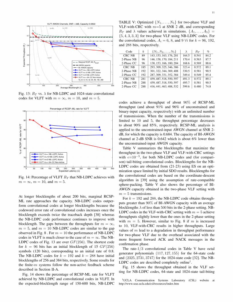
At longer blocklengths of about 200 bits, marginal RCSP-ML rate approaches the capacity. NB-LDPC codes outper-form convolutional codes at longer blocklengths because thecodeword error rate of convolutional codes increases once theblocklength exceeds twice the traceback depth [38] whereasthe NB-LDPC code performance continues to improve withblocklength. The gaps between the throughputs for m = ∞,m = 5, and m = 10 NB-LDPC codes are similar to the gapobserved in Fig. 8 . For m = 10 the performance of NB-LDPCcodes in VLFT is much closer to the case of m =∞. The NB-LDPC codes of Fig. 13 are over GF (256). The shortest codefor k = 96 bits has an initial blocklength of 15 GF (256)symbols (120 bits), corresponding to an initial rate of 0.8.The NB-LDPC codes for k = 192 and k = 288 have initialblocklengths of 256 and 384 bits, respectively. Some results forthe finite-m systems follow the non-active feedback schemedescribed in Section II-A.
Fig. 14 shows the percentage of RCSP-ML rate for VLFTachieved by NB-LDPC and convolutional codes in VLFT. Inthe expected-blocklength range of 150-600 bits, NB-LDPC
TABLE V: Optimized {N1, . . . , N5} for two-phase VLF andVLF-with-CRC with m=5 at SNR 2 dB, and correspondingRT and λ values achieved in simulations. {A1, . . . , A5} ={5, 4, 3, 3, 3} for two-phase VLF using NB-LDPC codes. Forthe convolutional codes, Ai = 6, 8, and 9 ∀i for k = 96, 192,and 288 bits, respectively.
Code k {N1, N2, . . . , N5} λ RT %CRC NB 89 143, 153, 163, 176, 201 164.5 0.541 84.2
2-Phase NB 96 146, 158, 170, 184, 211 170.4 0.563 87.72-Phase CC 96 138, 153, 166, 180, 204 168.6 0.569 88.6
CRC NB 185 293, 309, 325, 346, 386 323.4 0.572 89.12-Phase NB 192 301, 322, 344, 369, 408 330.5 0.581 90.52-Phase CC 192 287, 309, 331, 352, 384 349.4 0.549 85.4
CRC NB 281 459, 487, 518, 550, 597 491.3 0.572 89.12-Phase NB 288 459, 487, 518, 550, 597 495.7 0.581 90.52-Phase CC 288 416, 441, 463, 488, 532 599.6 0.480 74.8
codes achieve a throughput of about 90% of RCSP-MLthroughput (and about 91% and 96% of unconstrained andbinary-input capacity, respectively) with an unlimited numberof transmissions. When the number of the transmissions islimited to 10 and 5, the throughput percentage decreasesto about 90% and 85%, respectively. RCSP-ML analysis isapplied to the unconstrained-input AWGN channel at SNR 2-dB, for which the capacity is 0.684. The capacity of BI-AWGNchannel at 2-dB SNR is 0.642 which is about 6% lower thanthe unconstrained-input AWGN capacity.
Table V summarizes the blocklengths that maximize thethroughput in the two-phase VLF and VLF-with-CRC settingswith ε=10−3, for both NB-LDPC codes and (for compari-son) tail-biting convolutional codes. Blocklengths for the NB-LDPC codes are obtained from (21-23) using ES on an opti-mization space limited by initial SDO results. Blocklengths forthe convolutional codes are based on the coordinate-descentalgorithm in [39] using the assumption of rate-compatiblesphere-packing. Table V also shows the percentage of BI-AWGN capacity obtained in the two-phase VLF setting withm = 5 transmissions.
For k = 192 and 288, the NB-LDPC code obtains through-puts greater than 90% of BI-AWGN capacity with an averageblocklengths λ of less than 500 bits in the 2-phase setting. NB-LDPC codes in the VLF-with-CRC setting with m = 5 achievethroughputs slightly lower than the ones in the 2-phase settingwith m = 5. However, similar to Fig. 8 if m is increasedto 10, VLF-with-CRC results in higher throughputs. Largevalues of m lead to a degradation in throughput performancefor two-phase VLF due to the overhead associated with themore frequent forward ACK and NACK messages in theconfirmation phase.
The rate-1/3 convolutional codes in Table V have octalgenerator polynomials (117, 127, 155) for the 64-state codeand (2325, 2731, 3747) for the 1024-state code [32]. The NB-LDPC codes are described completely online1.
Fig. 15 shows the throughput obtained in the VLF set-ting for NB-LDPC codes, 64-state and 1024-state tail-biting
1UCLA Communication Systems Laboratory (CSL) website athttp://www.seas.ucla.edu/csl/resources/index.htm

12
0 100 200 300 400 500 6000.2
0.25
0.3
0.35
0.4
0.45
0.5
0.55
0.6
0.65
0.7
Average Blocklength (λ)
Exp
ecte
d T
hro
ug
hp
ut
(Rt )
BI−AWGN Channel, SNR = 2dB, Capacity=0.6422, ε=10−3
k=32
k=64
k=16
k=88 k=184 k=280
k=96
BI−AWGN capacity
VLF random coding lower bound
VLF CRC m=∞ NB−LDPC ActiveVLF CRC m=10 NB−LDPC Non-Active VLF CRC m=5 NB−LDPC Non-ActiveVLF Two−phase m=5 1024−CC VLF Non-Active
Two−phase m=5 64−CC Non-ActiveVLF Two−phase m=5 NB−LDPC Active Max. rate for fixed length code, no feedback
Rt=k/λ k=16, 32, 64, 88, 184, 280
Fig. 15: RT vs. λ for NB-LDPC with m = ∞ in VLF-with-CRC and 64 and 1024-state convolutional codes and NB-LDPC codes with m = 5 in VLF.
150 200 250 300 350 400 450 500 550 60075
80
85
90
95
100
% T
hro
ughput of B
I−A
WG
N C
apacity
Average Blocklength (λ)
VLF BI−AWGN Channel, SNR = 2dB, Capacity=0.6422
VLF Lower bound
VLF CRC m=∞ NB−LDPC Active VLF CRC m=10 NB−LDPC Non-Active VLF CRC m=5 NB−LDPC Non-Active VLF Two−phase m=5 NB−LDPC Active VLF Two−phase m=5 64−CC Non-Active
Fig. 16: Percentage of BI-AWGN capacity that NB-LDPC andconvolutional codes achieve in VLF.
convolutional codes with m = 5, m = 10, m = ∞ forε = 10−3. As the blocklength increases, as mentioned in[28], the performance of the codes in VLF gets closer to theperformance in VLFT. The plots for m = 5 are from TableV. With m = ∞, the k = 89 the NB-LDPC code achievesa throughput greater than the random coding lower boundobtained from the analysis in [2].
Fig. 16 shows the percentage of the capacity of the BI-AWGN channel at 2-dB SNR achieved by NB-LDPC andconvolutional codes using VLF. In the expected blocklengthrange of 300-500 bits, NB-LDPC codes with CRC achieve athroughput of about 94% of capacity with an unlimited numberof transmissions. When the number of the transmissions islimited to 10, the throughput percentage decreases to about93%. For m = 5, NB-LDPC codes perform slightly better intwo-phase VLF setting than in VLF-with-CRC. Note that form = ∞ or even m = 10 two-phase VLF will not performwell because of the overhead associated with the confirmationmessages.
As discussed in Section II-B similar Gaussian approxima-tion analysis can be done for higher-SNR AWGN channels.for instance, for SNR-8dB AWGN channel which uses a larger16-QAM constellation, the VLF-with-CRC system with anunlimited number of transmissions achieves a throughput of2.37 bits per symbol with a frame error probability of lessthan 10−3. This throughput corresponds to 88% of capacityin the blocklength regime of 40 16-QAM (quadrature ampli-tude modulation) symbols. Furthermore, the VLF-with-CRCsystem on 5-dB BI-AWGN fading channel with an unlimitednumber of transmissions achieves a throughput correspondingto 90% of capacity in the blocklength regime of about 140bits.
VIII. CONCLUSION
This paper uses the reciprocal-Gaussian approximation forthe blocklength of first successful decoding to optimize thesize of each incremental transmission to maximize throughputin VLFT and VLF settings. For feedback with a limitation onthe number of transmissions, the sequential differential opti-mization (SDO) algorithm can be used quickly and accuratelyto find the optimal transmission lengths for a wide range ofchannels and codes. In this paper we applied SDO to non-binary LDPC codes for a variety of feedback systems. Wefocused on the binary-input AWGN channel but verified theeffectiveness of the Gaussian approximation and SDO on thestandard AWGN channel with a 16-QAM input and on a fadingchannel. In the 300-500 bit average blocklength regime, thispaper reports the best VLFT and VLF throughputs yet. VLFTthroughputs are higher than VLF, but VLF is more practicalbecause it does not assume a noiseless transmitter confirmationsymbol. For VLF-with-CRC with m = ∞, NB-LDPC codeswith optimized blocklengths achieve about 94% of the capacityof 2-dB BI-AWGN channel for an average blocklength of 300-500 bits. In the same blocklength regime, for VLF-with-CRCwith m = 10, NB-LDPC codes with optimized blocklengthsachieve about 93% of the capacity.
The performance results can also be considered in terms ofSNR gap. In Fig. 16, the random-coding lower bound for asystem with feedback is 0.27 dB from the Shannon limit fork = 280 with a blocklength of less than 500 bits. Lookingat the VLF-CRC NB-LDPC codes for k = 280 in Fig. 16,the m = ∞ NB-LDPC code is 0.53 dB from Shannon limit.The NB-LDPC non-active feedback system in Fig. 16 uses tenrounds of single-bit feedback to operate within 0.65 dB of theShannon limit with an average blocklength of less than 500bits. Similar analysis can also be done for higher-SNR AWGNand fading channels.
REFERENCES
[1] C. E. Shannon, “The zero error capacity of a noisy channel,” IRE Trans.
Inf. Theory, vol. 2, no. 3, pp. 8–19, Sep. 1956.[2] Y. Polyanskiy, H. V. Poor, and S. Verdu, “Feedback in the non-
asymptotic regime,” IEEE Trans. Inf. Theory, vol. 57, no. 8, pp. 4903–4925, Aug. 2011.
[3] T.-Y. Chen, N. Seshadri, and R. Wesel, “A sphere-packing analysisof incremental redundancy with feedback,” in 2011 IEEE Int. Conf.
Commun. (ICC), June 2011, pp. 1–5.

13
[4] Y. Polyanskiy, H. V. Poor, and S. Verdu, “Channel coding rate in thefinite blocklength regime,” IEEE Trans. Inf. Theory, vol. 56, no. 5, pp.2307–2359, May 2010.
[5] S. Lin and P. Yu, “A hybrid arq scheme with parity retransmission forerror control of satellite channels,” IEEE Trans. Commun., vol. 30, no. 7,pp. 1701–1719, July 1982.
[6] J. Costello, D.J., J. Hagenauer, H. Imai, and S. Wicker, “Applicationsof error-control coding,” IEEE Trans. Inf. Theory, vol. 44, no. 6, pp.2531–2560, Oct. 1998.
[7] E. Visotsky, Y. Sun, V. Tripathi, M. Honig, and R. Peterson, “Reliability-based incremental redundancy with convolutional codes,” IEEE Trans.
Commun., vol. 53, no. 6, pp. 987– 997, June 2005.[8] C. Lott, O. Milenkovic, and E. Soljanin, “Hybrid ARQ: Theory, state of
the art and future directions,” in 2007 IEEE Inf. Theory Workshop for
Wireless Networks, Bergen, Norway, July 2007.[9] J. Fricke and P. Hoeher, “Reliability-based retransmission criteria for
hybrid ARQ,” IEEE Trans. Commun., vol. 57, no. 8, pp. 2181–2184,Aug. 2009.
[10] M. Heindlmaier and E. Soljanin, “Isn’t hybrid ARQ sufficient?” CoRR,vol. abs/1411.4061, 2014. [Online]. Available: http://arxiv.org/abs/1411.4061
[11] A. Roongta and J. Shea, “Reliability-based hybrid ARQ using convo-lutional codes,” in Proc. 2003 IEEE Int. Conf. Commun. (ICC), vol. 4,May 2003, pp. 2889–2893.
[12] ——, “Reliability-based hybrid ARQ and rate-compatible puncturedconvolutional (RCPC) codes,” in Proc. 2004 IEEE Wireless Commun.
and Networking Conf. (WCNC), vol. 4, Mar. 2004, pp. 2105–2109.[13] L. Bahl, J. Cocke, F. Jelinek, and J. Raviv, “Optimal decoding of
linear codes for minimizing symbol error rate,” IEEE Trans. Inf. Theory,vol. 20, no. 2, pp. 284–287, 1974.
[14] A. Raghavan and C. Baum, “A reliability output Viterbi algorithm withapplications to hybrid ARQ,” IEEE Trans. Inf. Theory, vol. 44, no. 3,pp. 1214–1216, May 1998.
[15] J. C. Fricke, H. Schoeneich, and P. A. Hoeher, “Reliability-based HARQusing word error probabilities,” in Proc. 2006 NEWCOM-ACoRN Joint
Workshop (NAW).[16] J. Fricke and P. Hoeher, “Word error probability estimation by means
of a modified Viterbi decoder,” in Proc. 66th IEEE Veh. Technol. Conf.
(VTC), Oct. 2007, pp. 1113–1116.[17] A. R. Williamson, M. J. Marshall, and R. D. Wesel, “Reliability-output
decoding of tail-biting convolutional codes,” IEEE Trans. Commun.,vol. 62, no. 6, pp. 1768–1778, June 2014.
[18] E. Soljanin, N. Varnica, and P. Whiting, “Incremental redundancyhybrid ARQ with LDPC and Raptor codes,” 2005. [Online]. Available:ftp://netlib.bell-labs.com/cm/ms/who/emina/papers/hybridarq final.pdf
[19] ——, “Punctured vs rateless codes for hybrid ARQ,” in Proc. 2006 IEEE
Inf. Theory Workshop (ITW), Punta del Este, Uruguay, Mar. 2006, pp.155–159.
[20] I. Andriyanova and E. Soljanin, “IR-HARQ schemes with finite-lengthpunctured LDPC codes over the BEC,” in Proc. 2009 IEEE Inf. Theory
Workshop (ITW), Taormina, Sicily, Oct. 2009, pp. 125 –129.[21] ——, “Optimized IR-HARQ schemes based on punctured LDPC codes
over the BEC,” IEEE Trans. Inf. Theory, vol. 58, no. 10, pp. 6433–6445,Oct. 2012.
[22] J. Perry, H. Balakrishnan, and D. Shah, “Rateless spinal codes,” in Proc.
10th ACM Workshop on Hot Topics in Networks, 2011.[23] J. Perry, P. A. Iannucci, K. E. Fleming, H. Balakrishnan, and D. Shah,
“Spinal codes,” in Proc. 2012 ACM SIGCOMM Conf. on Applicat.,
Tech., Arch., and Protocols for Comput. Commun., Helsinki, Finland,2012, pp. 49–60.
[24] D. L. Romero, “A comparative analysis of physical-layer rateless codingarchitectures,” Master’s thesis, MIT, Cambridge, MA, 2014.
[25] K. Chen, K. Niu, and J.-R. Lin, “A hybrid ARQ scheme based on polarcodes,” IEEE Commun. Lett., vol. 17, no. 10, pp. 1996–1999, Oct. 2013.
[26] K. Chen, K. Niu, Z. He, and J.-R. Lin, “Polar coded HARQ scheme withChase combining,” in Proc. 2014 IEEE Wireless Commun. and Network
Conf. (WCNC), Apr. 2014, pp. 474–479.[27] S. Pfletschinger, D. Declercq, and M. Navarro, “Adaptive HARQ with
non-binary repetition coding,” IEEE Trans. on Wireless Commun.,vol. 13, no. 8, pp. 4193–4204, Aug. 2014.
[28] T.-Y. Chen, A. R. Williamson, N. Seshadri, and R. D. Wesel, “Feedbackcommunication systems with limitations on incremental redundancy,”Available: http://arxiv.org/abs/1309.0707.
[29] A. Williamson, T.-Y. Chen, and R. Wesel, “A rate-compatible sphere-packing analysis of feedback coding with limited retransmissions,” in2012 IEEE Int. Symp. Inf. Theory (ISIT), July 2012, pp. 2924–2928.
[30] ——, “Variable-length convolutional coding for short blocklengths withdecision feedback,” IEEE Trans. Commun., vol. 63, no. 7, pp. 2389–2403, July 2015.
[31] B.-Y. Chang, D. Divsalar, and L. Dolecek, “Non-binary protograph-based LDPC codes for short block-lengths,” in 2012 IEEE Inf. Theory
Workshop (ITW), Sep. 2012, pp. 282–286.[32] K. Vakilinia, T.-Y. Chen, S. V. S. Ranganathan, A. R. Williamson,
D. Divsalar, and R. D. Wesel, “Short-blocklength non-binary LDPCcodes with feedback-dependent incremental transmissions,” in Proc.
2014 IEEE Int. Symp. Inf. Theory (ISIT), Honolulu, HI, USA, July 2014.[33] K. Vakilinia, A. Williamson, S. Ranganathan, D. Divsalar, and R. Wesel,
“Feedback systems using non-binary LDPC codes with a limited numberof transmissions,” in Inf. Theory Workshop (ITW), 2014 IEEE, Nov 2014,pp. 167–171.
[34] M. Naghshvar, T. Javidi, and M. A. Wigger, “Extrinsic jensen-shannon divergence: Applications to variable-length coding,” CoRR, vol.abs/1307.0067, 2013.
[35] T. Chen, K. Vakilinia, D. Divsalar, and R. Wesel, “Protograph-basedraptor-like LDPC codes,” IEEE Trans. Commun., vol. 63, no. 5, pp.1522–1532, May 2015.
[36] C.-Y. Lou, B. Daneshrad, and R. Wesel, “Convolutional-code-specificcrc code design,” IEEE Trans. Commun., to be published. Available:http://arxiv.org/abs/1506.02990.
[37] A. Williamson, T.-Y. Chen, and R. Wesel, “Firing the genie: Two-phase short-blocklength convolutional coding with feedback,” in 2013
Inf. Theory and Applications Workshop (ITA), 2013, pp. 1–6.[38] J. Anderson and K. Balachandran, “Decision depths of convolutional
codes,” IEEE Trans. Inf. Theory, vol. 35, no. 2, pp. 455–459, Mar. 1989.[39] A. R. Williamson, “Reliability-output decoding and low-latency
variable-length coding schemes for communication with feedback,”Ph.D. dissertation, Dept. Elec. Eng., UCLA, Los Angeles, CA, 2014.