Optimizing For Hardware Transform and Lighting Optimizing For
2114 West 7th Street Tempe, AZ 85281 USA Voice +1.480.333.2200
E-mail [email protected] Web www.comtechefdata.com
Optimizing Satellite Communications Using
DoubleTalk® Carrier-in-Carrier®& CDM-625 Advanced Satellite Modem
December 2010
© 2010 Comtech EF Data Corporation
Carrier-in-Carrier is a Registered Trademark of Comtech EF Data DoubleTalk is a Registered Trademark of Applied Signal Technology, Inc
Optimizing Satellite Communications Using DoubleTalk® Carrier-in-Carrier® & CDM-625 Advanced Satellite Modem December 2010
1 | P a g e
Introduction Space segment costs are typically the most significant operating expense for any satellite-based service, having a direct impact on the viability and profitability of the service. A satellite transponder having finite resources in terms of bandwidth and power, the transponder leasing costs are determined by bandwidth and power used. For optimal utilization, a satellite circuit should be designed to use similar share of transponder bandwidth and transponder power. Once the satellite and earth station parameters are fixed, the traditional approach to balancing a satellite circuit involves trade-off between modulation and coding. A lower order modulation requires less transponder power while using more bandwidth. Conversely, higher order modulation reduces required bandwidth, but at a significant increase in power. Comtech EF Data has added a new dimension to satellite communication optimization – DoubleTalk® Carrier-in-Carrier® (CnC). This innovative technology provides a significant improvement in bandwidth and power utilization, beyond what is possible with forward error correction (FEC) and modulation alone, allowing users to achieve unprecedented savings. When combined with advanced Modulation and FEC, it allows for multi dimensional optimization
Reducing OPEX Occupied Bandwidth & Transponder Power
Reducing CAPEX BUC/HPA Size and/or Antenna Size
Increasing throughput without using additional transponder resources Increasing link availability (margin) without using additional transponder resources Or, a combination to meet different objectives
DoubleTalk Carrier-in-Carrier
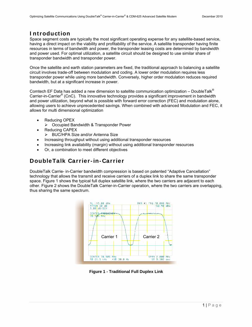
DoubleTalk Carrie- in-Carrier bandwidth compression is based on patented “Adaptive Cancellation” technology that allows the transmit and receive carriers of a duplex link to share the same transponder space. Figure 1 shows the typical full duplex satellite link, where the two carriers are adjacent to each other. Figure 2 shows the DoubleTalk Carrier-in-Carrier operation, where the two carriers are overlapping, thus sharing the same spectrum.
Figure 1 - Traditional Full Duplex Link
Carrier 1 Carrier 2
Optimizing Satellite Communications Using DoubleTalk® Carrier-in-Carrier® & CDM-625 Advanced Satellite Modem December 2010
2 | P a g e
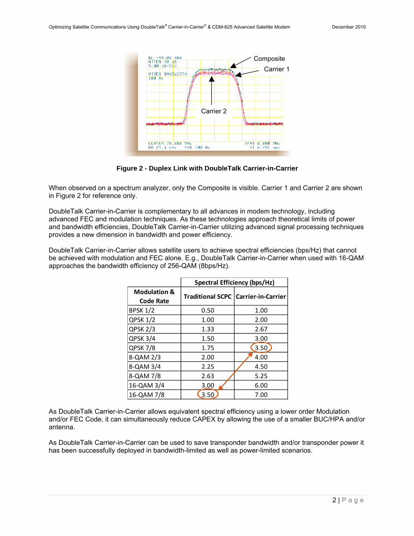
Figure 2 - Duplex Link with DoubleTalk Carrier-in-Carrier
When observed on a spectrum analyzer, only the Composite is visible. Carrier 1 and Carrier 2 are shown in Figure 2 for reference only. DoubleTalk Carrier-in-Carrier is complementary to all advances in modem technology, including advanced FEC and modulation techniques. As these technologies approach theoretical limits of power and bandwidth efficiencies, DoubleTalk Carrier-in-Carrier utilizing advanced signal processing techniques provides a new dimension in bandwidth and power efficiency. DoubleTalk Carrier-in-Carrier allows satellite users to achieve spectral efficiencies (bps/Hz) that cannot be achieved with modulation and FEC alone. E.g., DoubleTalk Carrier-in-Carrier when used with 16-QAM approaches the bandwidth efficiency of 256-QAM (8bps/Hz).
As DoubleTalk Carrier-in-Carrier allows equivalent spectral efficiency using a lower order Modulation and/or FEC Code, it can simultaneously reduce CAPEX by allowing the use of a smaller BUC/HPA and/or antenna. As DoubleTalk Carrier-in-Carrier can be used to save transponder bandwidth and/or transponder power it has been successfully deployed in bandwidth-limited as well as power-limited scenarios.
Composite
Carrier 2
Carrier 1
Modulation &
Code RateTraditional SCPC Carrier‐in‐Carrier
BPSK 1/2 0.50 1.00
QPSK 1/2 1.00 2.00
QPSK 2/3 1.33 2.67
QPSK 3/4 1.50 3.00
QPSK 7/8 1.75 3.50
8‐QAM 2/3 2.00 4.00
8‐QAM 3/4 2.25 4.50
8‐QAM 7/8 2.63 5.25
16‐QAM 3/4 3.00 6.00
16‐QAM 7/8 3.50 7.00
Spectral Efficiency (bps/Hz)
Optimizing Satellite Communications Using DoubleTalk® Carrier-in-Carrier® & CDM-625 Advanced Satellite Modem December 2010
3 | P a g e
DoubleTalk Carrier-in-Carrier Cancellation Process
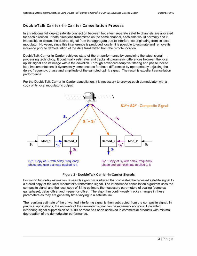
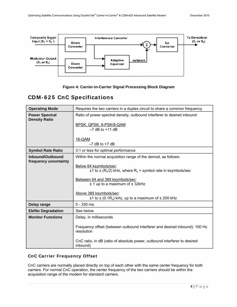
In a traditional full duplex satellite connection between two sites, separate satellite channels are allocated for each direction. If both directions transmitted on the same channel, each side would normally find it impossible to extract the desired signal from the aggregate due to interference originating from its local modulator. However, since this interference is produced locally, it is possible to estimate and remove its influence prior to demodulation of the data transmitted from the remote location. DoubleTalk Carrier-in-Carrier achieves state-of-the-art performance by combining the latest signal processing technology. It continually estimates and tracks all parametric differences between the local uplink signal and its image within the downlink. Through advanced adaptive filtering and phase locked loop implementations, it dynamically compensates for these differences by appropriately adjusting the delay, frequency, phase and amplitude of the sampled uplink signal. The result is excellent cancellation performance. For the DoubleTalk Carrier-in-Carrier cancellation, it is necessary to provide each demodulator with a copy of its local modulator’s output.
Mod_1 Demod_1 Demod_2 Mod_2
S1 S2S1
*'+ S2*'
S1* S2
*S1 S2
S2 S1
S1*'+ S2*' : Composite Signal
S1* : Copy of S1 with delay, frequency, phase and gain estimate applied to it
S2* : Copy of S2 with delay, frequency, phase and gain estimate applied to it
Figure 3 - DoubleTalk Carrier-in-Carrier Signals
For round trip delay estimation, a search algorithm is utilized that correlates the received satellite signal to a stored copy of the local modulator’s transmitted signal. The interference cancellation algorithm uses the composite signal and the local copy of S1 to estimate the necessary parameters of scaling (complex gain/phase), delay offset and frequency offset. The algorithm continuously tracks changes in these parameters as they are generally time-varying in a satellite link. The resulting estimate of the unwanted interfering signal is then subtracted from the composite signal. In practical applications, the estimate of the unwanted signal can be extremely accurate. Unwanted interfering signal suppression of 30 dB or more has been achieved in commercial products with minimal degradation of the demodulator performance.
Optimizing Satellite Communications Using DoubleTalk® Carrier-in-Carrier® & CDM-625 Advanced Satellite Modem December 2010
4 | P a g e
Figure 4: Carrier-in-Carrier Signal Processing Block Diagram
CDM-625 CnC Specifications
Operating Mode Requires the two carriers in a duplex circuit to share a common frequency
Power Spectral Density Ratio
Ratio of power spectral density, outbound interferer to desired inbound: BPSK, QPSK, 8-PSK/8-QAM
–7 dB to +11 dB
16-QAM –7 dB to +7 dB
Symbol Rate Ratio 3:1 or less for optimal performance
Inbound/Outbound frequency uncertainty
Within the normal acquisition range of the demod, as follows: Below 64 ksymbols/sec:
±1 to ± (Rs/2) kHz, where Rs = symbol rate in ksymbols/sec Between 64 and 389 ksymbols/sec:
± 1 up to a maximum of ± 32kHz Above 389 ksymbols/sec:
±1 to ± (0.1Rs) kHz, up to a maximum of ± 200 kHz
Delay range 0 - 330 ms
Eb/No Degradation See below
Monitor Functions Delay, in milliseconds Frequency offset (between outbound interferer and desired inbound): 100 Hz resolution CnC ratio, in dB (ratio of absolute power, outbound interferer to desired inbound)
CnC Carrier Frequency Offset
CnC carriers are normally placed directly on top of each other with the same center frequency for both carriers. For normal CnC operation, the center frequency of the two carriers should be within the acquisition range of the modem for standard carriers.
Optimizing Satellite Communications Using DoubleTalk® Carrier-in-Carrier® & CDM-625 Advanced Satellite Modem December 2010
5 | P a g e
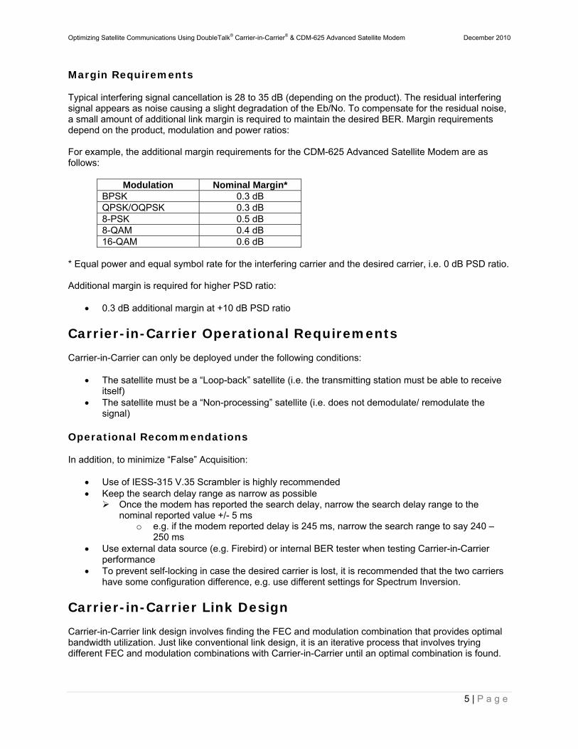
Margin Requirements
Typical interfering signal cancellation is 28 to 35 dB (depending on the product). The residual interfering signal appears as noise causing a slight degradation of the Eb/No. To compensate for the residual noise, a small amount of additional link margin is required to maintain the desired BER. Margin requirements depend on the product, modulation and power ratios: For example, the additional margin requirements for the CDM-625 Advanced Satellite Modem are as follows:
Modulation Nominal Margin* BPSK 0.3 dB QPSK/OQPSK 0.3 dB 8-PSK 0.5 dB 8-QAM 0.4 dB 16-QAM 0.6 dB
* Equal power and equal symbol rate for the interfering carrier and the desired carrier, i.e. 0 dB PSD ratio. Additional margin is required for higher PSD ratio:
0.3 dB additional margin at +10 dB PSD ratio
Carrier-in-Carrier Operational Requirements
Carrier-in-Carrier can only be deployed under the following conditions:
The satellite must be a “Loop-back” satellite (i.e. the transmitting station must be able to receive itself)
The satellite must be a “Non-processing” satellite (i.e. does not demodulate/ remodulate the signal)
Operational Recommendations
In addition, to minimize “False” Acquisition:
Use of IESS-315 V.35 Scrambler is highly recommended Keep the search delay range as narrow as possible
Once the modem has reported the search delay, narrow the search delay range to the nominal reported value +/- 5 ms
o e.g. if the modem reported delay is 245 ms, narrow the search range to say 240 – 250 ms
Use external data source (e.g. Firebird) or internal BER tester when testing Carrier-in-Carrier performance
To prevent self-locking in case the desired carrier is lost, it is recommended that the two carriers have some configuration difference, e.g. use different settings for Spectrum Inversion.
Carrier-in-Carrier Link Design
Carrier-in-Carrier link design involves finding the FEC and modulation combination that provides optimal bandwidth utilization. Just like conventional link design, it is an iterative process that involves trying different FEC and modulation combinations with Carrier-in-Carrier until an optimal combination is found.
Optimizing Satellite Communications Using DoubleTalk® Carrier-in-Carrier® & CDM-625 Advanced Satellite Modem December 2010
6 | P a g e
For optimal Carrier-in-Carrier performance, it is recommended that the two carriers have similar symbol rate and power. This can be achieved by selecting appropriate MODCODs as shown in following sections.
Symmetric Data Rate Link
Consider the following example:
Satellite & Transponder Galaxy 18 @ 123º W, 13K/13K Earth Station 1
Phoenix, AZ 4.6 m
Earth Station 2
Phoenix, AZ 2.4 m
Data Rate 512 kbps / 512 kbps Availability ≥ 99.97%
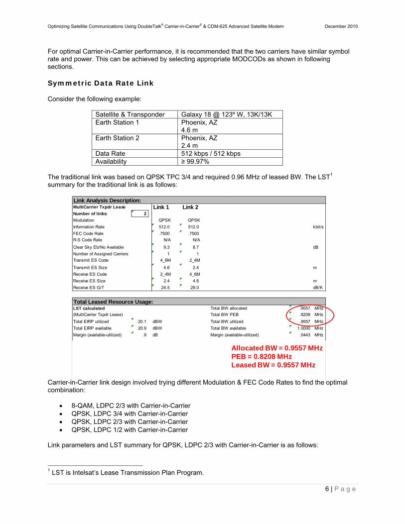
The traditional link was based on QPSK TPC 3/4 and required 0.96 MHz of leased BW. The LST1 summary for the traditional link is as follows:
Carrier-in-Carrier link design involved trying different Modulation & FEC Code Rates to find the optimal combination:
8-QAM, LDPC 2/3 with Carrier-in-Carrier QPSK, LDPC 3/4 with Carrier-in-Carrier QPSK, LDPC 2/3 with Carrier-in-Carrier QPSK, LDPC 1/2 with Carrier-in-Carrier
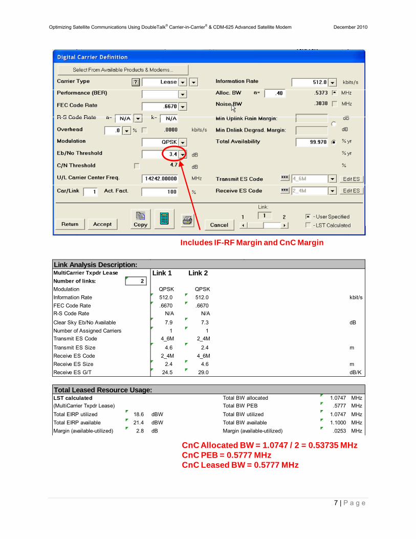
Link parameters and LST summary for QPSK, LDPC 2/3 with Carrier-in-Carrier is as follows:
1 LST is Intelsat’s Lease Transmission Plan Program.
Link Analysis Description: MultiCarrier Txpdr Lease Link 1 Link 2 Number of links: 2
Modulation QPSK QPSK
Information Rate 512.0 512.0 kbit/s
FEC Code Rate .7500 .7500
R-S Code Rate N/A N/A
Clear Sky Eb/No Available 9.3 8.7 dB
Number of Assigned Carriers 1 1
Transmit ES Code 4_6M 2_4M
Transmit ES Size 4.6 2.4 m
Receive ES Code 2_4M 4_6M
Receive ES Size 2.4 4.6 m
Receive ES G/T 24.5 29.0 dB/K
Total Leased Resource Usage:LST calculated Total BW allocated .9557 MHz
(MultiCarrier Txpdr Lease) Total BW PEB .8208 MHz
Total EIRP utilized 20.1 dBW Total BW utilized .9557 MHz
Total EIRP available 20.9 dBW Total BW available 1.0000 MHz
Margin (available-utilized) .9 dB Margin (available-utilized) .0443 MHz
Allocated BW = 0.9557 MHzPEB = 0.8208 MHzLeased BW = 0.9557 MHz
Optimizing Satellite Communications Using DoubleTalk® Carrier-in-Carrier® & CDM-625 Advanced Satellite Modem December 2010
7 | P a g e
Includes IF-RF Margin and CnC Margin
CnC Allocated BW = 1.0747 / 2 = 0.53735 MHzCnC PEB = 0.5777 MHzCnC Leased BW = 0.5777 MHz
Link Analysis Description: MultiCarrier Txpdr Lease Link 1 Link 2 Number of links: 2
Modulation QPSK QPSK
Information Rate 512.0 512.0 kbit/s
FEC Code Rate .6670 .6670
R-S Code Rate N/A N/A
Clear Sky Eb/No Available 7.9 7.3 dB
Number of Assigned Carriers 1 1
Transmit ES Code 4_6M 2_4M
Transmit ES Size 4.6 2.4 m
Receive ES Code 2_4M 4_6M
Receive ES Size 2.4 4.6 m
Receive ES G/T 24.5 29.0 dB/K
Total Leased Resource Usage:LST calculated Total BW allocated 1.0747 MHz
(MultiCarrier Txpdr Lease) Total BW PEB .5777 MHz
Total EIRP utilized 18.6 dBW Total BW utilized 1.0747 MHz
Total EIRP available 21.4 dBW Total BW available 1.1000 MHz
Margin (available-utilized) 2.8 dB Margin (available-utilized) .0253 MHz
Optimizing Satellite Communications Using DoubleTalk® Carrier-in-Carrier® & CDM-625 Advanced Satellite Modem December 2010
8 | P a g e
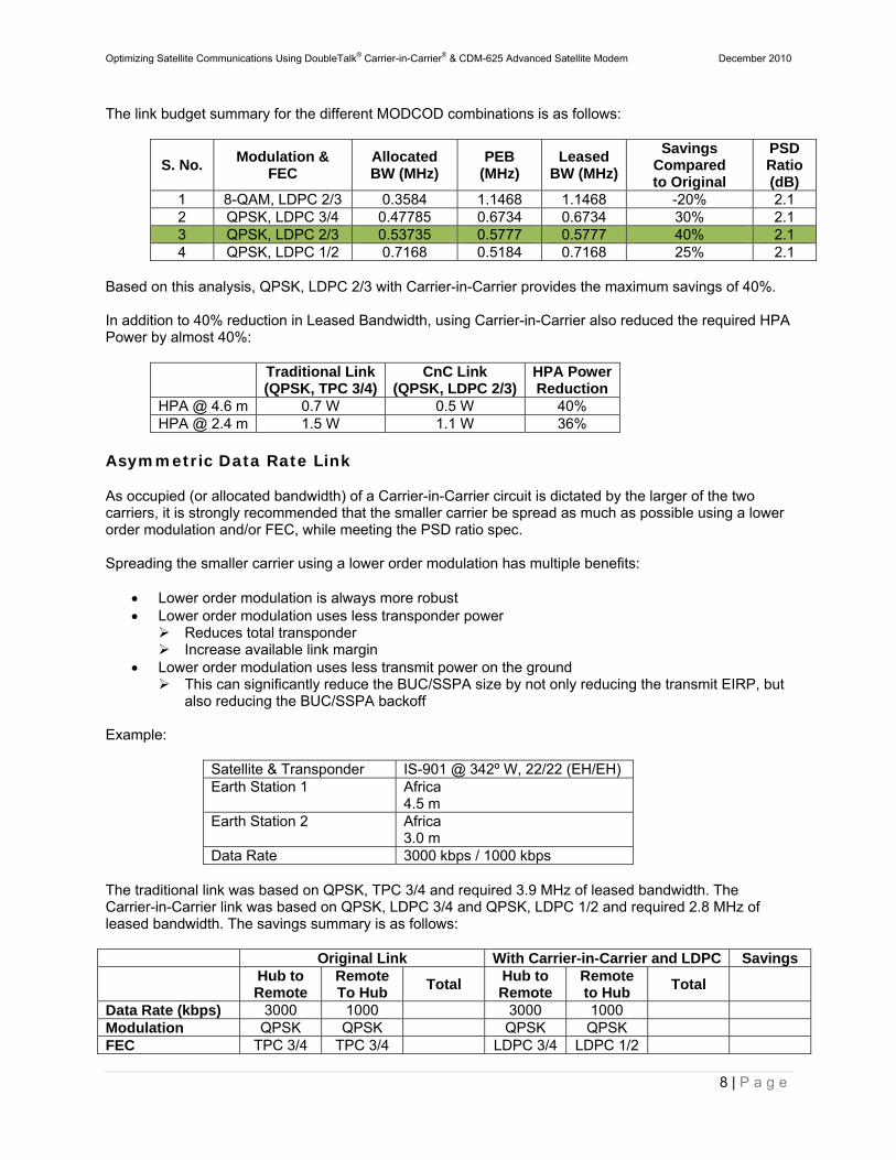
The link budget summary for the different MODCOD combinations is as follows:
S. No. Modulation &
FEC Allocated BW (MHz)
PEB (MHz)
Leased BW (MHz)
Savings Compared to Original
PSD Ratio(dB)
1 8-QAM, LDPC 2/3 0.3584 1.1468 1.1468 -20% 2.1 2 QPSK, LDPC 3/4 0.47785 0.6734 0.6734 30% 2.1 3 QPSK, LDPC 2/3 0.53735 0.5777 0.5777 40% 2.1 4 QPSK, LDPC 1/2 0.7168 0.5184 0.7168 25% 2.1
Based on this analysis, QPSK, LDPC 2/3 with Carrier-in-Carrier provides the maximum savings of 40%. In addition to 40% reduction in Leased Bandwidth, using Carrier-in-Carrier also reduced the required HPA Power by almost 40%:
Traditional Link (QPSK, TPC 3/4)
CnC Link (QPSK, LDPC 2/3)
HPA Power Reduction
HPA @ 4.6 m 0.7 W 0.5 W 40% HPA @ 2.4 m 1.5 W 1.1 W 36%
Asymmetric Data Rate Link
As occupied (or allocated bandwidth) of a Carrier-in-Carrier circuit is dictated by the larger of the two carriers, it is strongly recommended that the smaller carrier be spread as much as possible using a lower order modulation and/or FEC, while meeting the PSD ratio spec. Spreading the smaller carrier using a lower order modulation has multiple benefits:
Lower order modulation is always more robust Lower order modulation uses less transponder power
Reduces total transponder Increase available link margin
Lower order modulation uses less transmit power on the ground This can significantly reduce the BUC/SSPA size by not only reducing the transmit EIRP, but
also reducing the BUC/SSPA backoff Example:
Satellite & Transponder IS-901 @ 342º W, 22/22 (EH/EH) Earth Station 1
Africa 4.5 m
Earth Station 2
Africa 3.0 m
Data Rate 3000 kbps / 1000 kbps The traditional link was based on QPSK, TPC 3/4 and required 3.9 MHz of leased bandwidth. The Carrier-in-Carrier link was based on QPSK, LDPC 3/4 and QPSK, LDPC 1/2 and required 2.8 MHz of leased bandwidth. The savings summary is as follows:
Original Link With Carrier-in-Carrier and LDPC Savings
Hub to Remote
Remote To Hub
Total Hub to Remote
Remote to Hub
Total
Data Rate (kbps) 3000 1000 3000 1000 Modulation QPSK QPSK QPSK QPSK FEC TPC 3/4 TPC 3/4 LDPC 3/4 LDPC 1/2
Optimizing Satellite Communications Using DoubleTalk® Carrier-in-Carrier® & CDM-625 Advanced Satellite Modem December 2010
9 | P a g e
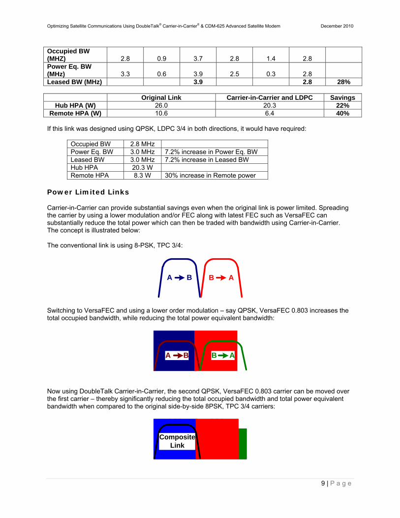
Occupied BW (MHZ) 2.8 0.9 3.7 2.8 1.4 2.8 Power Eq. BW (MHz) 3.3 0.6 3.9 2.5 0.3 2.8 Leased BW (MHz) 3.9 2.8 28%
Original Link Carrier-in-Carrier and LDPC Savings Hub HPA (W) 26.0 20.3 22%
Remote HPA (W) 10.6 6.4 40% If this link was designed using QPSK, LDPC 3/4 in both directions, it would have required:
Occupied BW 2.8 MHz Power Eq. BW 3.0 MHz 7.2% increase in Power Eq. BW Leased BW 3.0 MHz 7.2% increase in Leased BW Hub HPA 20.3 W Remote HPA 8.3 W 30% increase in Remote power
Power Limited Links
Carrier-in-Carrier can provide substantial savings even when the original link is power limited. Spreading the carrier by using a lower modulation and/or FEC along with latest FEC such as VersaFEC can substantially reduce the total power which can then be traded with bandwidth using Carrier-in-Carrier. The concept is illustrated below: The conventional link is using 8-PSK, TPC 3/4:
A B B A
Switching to VersaFEC and using a lower order modulation – say QPSK, VersaFEC 0.803 increases the total occupied bandwidth, while reducing the total power equivalent bandwidth:
A B B A
Now using DoubleTalk Carrier-in-Carrier, the second QPSK, VersaFEC 0.803 carrier can be moved over the first carrier – thereby significantly reducing the total occupied bandwidth and total power equivalent bandwidth when compared to the original side-by-side 8PSK, TPC 3/4 carriers:
CompositeLink
Optimizing Satellite Communications Using DoubleTalk® Carrier-in-Carrier® & CDM-625 Advanced Satellite Modem December 2010
10 | P a g e
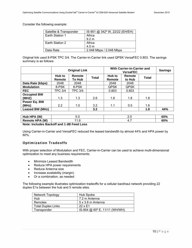
Consider the following example:
Satellite & Transponder IS-901 @ 342º W, 22/22 (EH/EH) Earth Station 1
Africa 9.2 m
Earth Station 2
Africa 4.5 m
Data Rate 2.048 Mbps / 2.048 Mbps Original link used 8-PSK TPC 3/4. The Carrier-in-Carrier link used QPSK VersaFEC 0.803. The savings summary is as follows:
Original Link With Carrier-in-Carrier and
VersaFEC Savings
Hub to Remote
Remote To Hub
Total Hub to Remote
Remote to Hub
Total
Data Rate (kbps) 2048 2048 2048 2048 Modulation 8-PSK 8-PSK QPSK QPSK FEC TPC 3/4 TPC 3/4 0.803 0.803 Occupied BW (MHZ) 1.3 1.3 2.6 1.8 1.8 1.8 Power Eq. BW (MHz) 2.2 1.0 3.2 1.1 0.5 1.6 Leased BW (MHz) 3.2 1.8 44% Hub HPA (W) 5.0 2.0 60% Remote HPA (W) 11.6 4.7 60% Note: Includes Backoff and 1 dB Feed Loss Using Carrier-in-Carrier and VersaFEC reduced the leased bandwidth by almost 44% and HPA power by 60%.
Optimization Tradeoffs
With proper selection of Modulation and FEC, Carrier-in-Carrier can be used to achieve multi-dimensional optimization to meet any business requirements:
Minimize Leased Bandwidth Reduce HPA power requirements Reduce Antenna size Increase availability (margin) Or a combination, as needed
The following example illustrates optimization tradeoffs for a cellular backhaul network providing 22 duplex E1s between the hub and 5 remote sites.
Network Topology Hub Spoke Hub 7.2 m Antenna Remotes 5 x 3.8 m Antenna Total Duplex Links 22 x E1 Transponder IS-904 @ 60º E, 11/11 (WH/WH)
Optimizing Satellite Communications Using DoubleTalk® Carrier-in-Carrier® & CDM-625 Advanced Satellite Modem December 2010
11 | P a g e
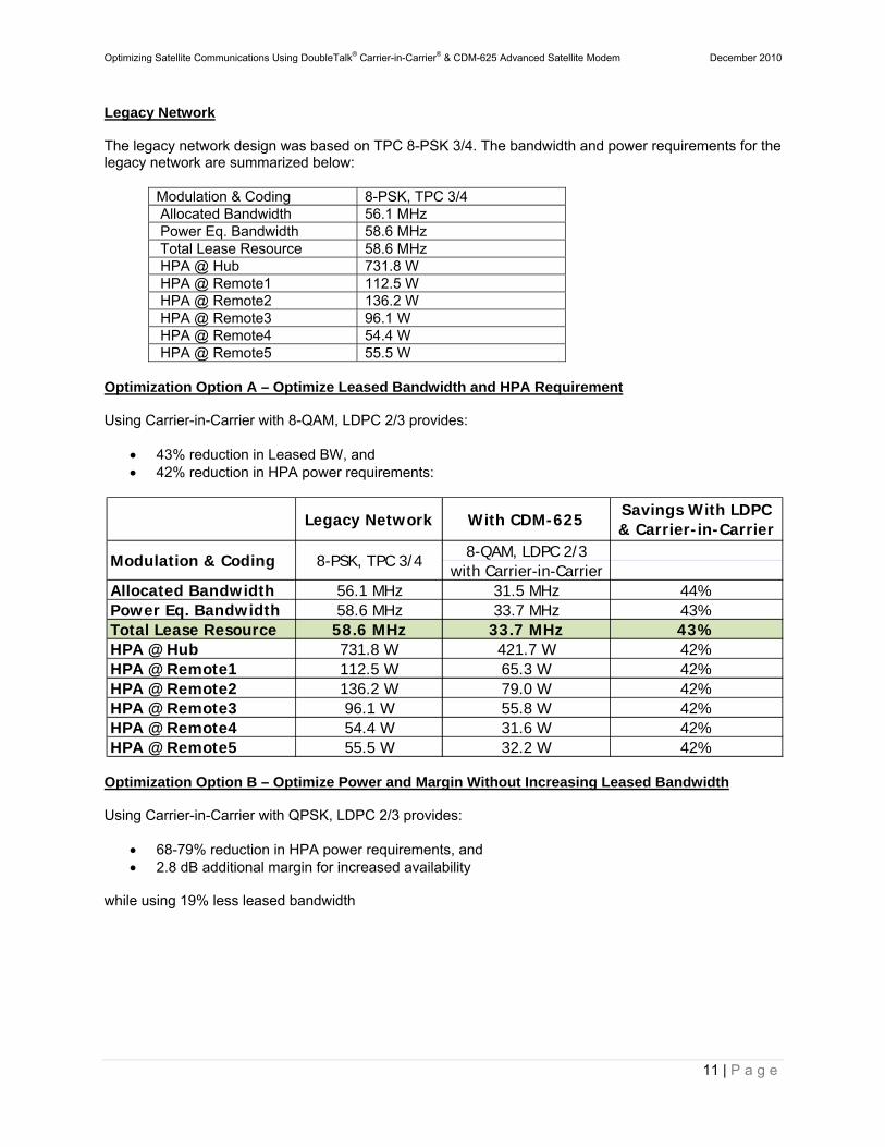
Legacy Network The legacy network design was based on TPC 8-PSK 3/4. The bandwidth and power requirements for the legacy network are summarized below:
Modulation & Coding 8-PSK, TPC 3/4 Allocated Bandwidth 56.1 MHz Power Eq. Bandwidth 58.6 MHz Total Lease Resource 58.6 MHz HPA @ Hub 731.8 W HPA @ Remote1 112.5 W HPA @ Remote2 136.2 W HPA @ Remote3 96.1 W HPA @ Remote4 54.4 W HPA @ Remote5 55.5 W
Optimization Option A – Optimize Leased Bandwidth and HPA Requirement Using Carrier-in-Carrier with 8-QAM, LDPC 2/3 provides:
43% reduction in Leased BW, and 42% reduction in HPA power requirements:
Optimization Option B – Optimize Power and Margin Without Increasing Leased Bandwidth Using Carrier-in-Carrier with QPSK, LDPC 2/3 provides:
68-79% reduction in HPA power requirements, and 2.8 dB additional margin for increased availability
while using 19% less leased bandwidth
Legacy Network With CDM-625Savings With LDPC & Carrier-in-Carrier
8-QAM, LDPC 2/3with Carrier-in-Carrier
Allocated Bandwidth 56.1 MHz 31.5 MHz 44%Power Eq. Bandwidth 58.6 MHz 33.7 MHz 43%Total Lease Resource 58.6 MHz 33.7 MHz 43%HPA @ Hub 731.8 W 421.7 W 42%HPA @ Remote1 112.5 W 65.3 W 42%HPA @ Remote2 136.2 W 79.0 W 42%HPA @ Remote3 96.1 W 55.8 W 42%HPA @ Remote4 54.4 W 31.6 W 42%HPA @ Remote5 55.5 W 32.2 W 42%
Modulation & Coding 8-PSK, TPC 3/4
Optimizing Satellite Communications Using DoubleTalk® Carrier-in-Carrier® & CDM-625 Advanced Satellite Modem December 2010
12 | P a g e
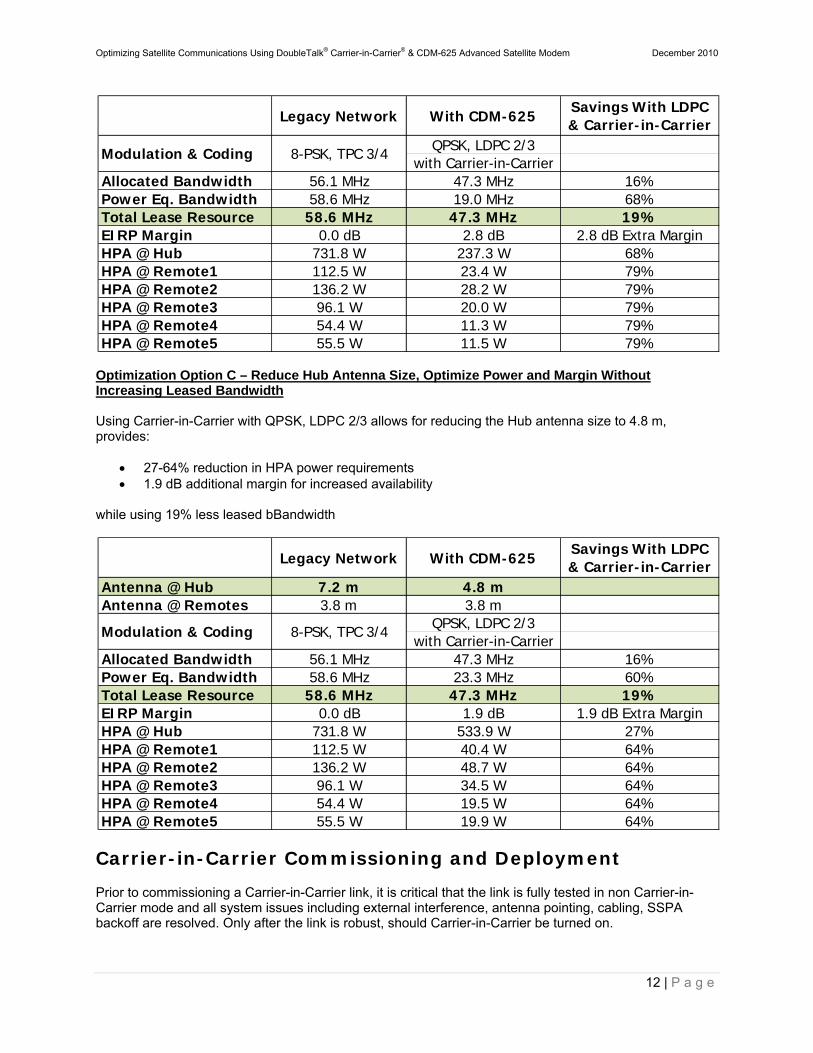
Optimization Option C – Reduce Hub Antenna Size, Optimize Power and Margin Without Increasing Leased Bandwidth Using Carrier-in-Carrier with QPSK, LDPC 2/3 allows for reducing the Hub antenna size to 4.8 m, provides:
27-64% reduction in HPA power requirements 1.9 dB additional margin for increased availability
while using 19% less leased bBandwidth
Carrier-in-Carrier Commissioning and Deployment
Prior to commissioning a Carrier-in-Carrier link, it is critical that the link is fully tested in non Carrier-in-Carrier mode and all system issues including external interference, antenna pointing, cabling, SSPA backoff are resolved. Only after the link is robust, should Carrier-in-Carrier be turned on.
Legacy Network With CDM-625Savings With LDPC & Carrier-in-Carrier
QPSK, LDPC 2/3with Carrier-in-Carrier
Allocated Bandwidth 56.1 MHz 47.3 MHz 16%Power Eq. Bandwidth 58.6 MHz 19.0 MHz 68%Total Lease Resource 58.6 MHz 47.3 MHz 19%EIRP Margin 0.0 dB 2.8 dB 2.8 dB Extra MarginHPA @ Hub 731.8 W 237.3 W 68%HPA @ Remote1 112.5 W 23.4 W 79%HPA @ Remote2 136.2 W 28.2 W 79%HPA @ Remote3 96.1 W 20.0 W 79%HPA @ Remote4 54.4 W 11.3 W 79%HPA @ Remote5 55.5 W 11.5 W 79%
Modulation & Coding 8-PSK, TPC 3/4
Legacy Network With CDM-625Savings With LDPC & Carrier-in-Carrier
Antenna @ Hub 7.2 m 4.8 mAntenna @ Remotes 3.8 m 3.8 m
QPSK, LDPC 2/3with Carrier-in-Carrier
Allocated Bandwidth 56.1 MHz 47.3 MHz 16%Power Eq. Bandwidth 58.6 MHz 23.3 MHz 60%Total Lease Resource 58.6 MHz 47.3 MHz 19%EIRP Margin 0.0 dB 1.9 dB 1.9 dB Extra MarginHPA @ Hub 731.8 W 533.9 W 27%HPA @ Remote1 112.5 W 40.4 W 64%HPA @ Remote2 136.2 W 48.7 W 64%HPA @ Remote3 96.1 W 34.5 W 64%HPA @ Remote4 54.4 W 19.5 W 64%HPA @ Remote5 55.5 W 19.9 W 64%
Modulation & Coding 8-PSK, TPC 3/4
Optimizing Satellite Communications Using DoubleTalk® Carrier-in-Carrier® & CDM-625 Advanced Satellite Modem December 2010
13 | P a g e
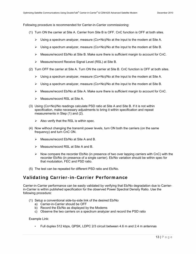
Following procedure is recommended for Carrier-in-Carrier commissioning:
(1) Turn ON the carrier at Site A. Carrier from Site B is OFF. CnC function is OFF at both sites.
Using a spectrum analyzer, measure (Co+No)/No at the input to the modem at Site A. Using a spectrum analyzer, measure (Co+No)/No at the input to the modem at Site B.
Measure/record Eb/No at Site B. Make sure there is sufficient margin to account for CnC.
Measure/record Receive Signal Level (RSL) at Site B.
(2) Turn OFF the carrier at Site A. Turn ON the carrier at Site B. CnC function is OFF at both sites.
Using a spectrum analyzer, measure (Co+No)/No at the input to the modem at Site A.
Using a spectrum analyzer, measure (Co+No)/No at the input to the modem at Site B.
Measure/record Eb/No at Site A. Make sure there is sufficient margin to account for CnC.
Measure/record RSL at Site A.
(3) Using (Co+No)/No readings calculate PSD ratio at Site A and Site B. If it is not within
specification, make necessary adjustments to bring it within specification and repeat measurements in Step (1) and (2).
Also verify that the RSL is within spec.
(4) Now without changing the transmit power levels, turn ON both the carriers (on the same
frequency) and turn CnC ON.
Measure/record Eb/No at Site A and B. Measure/record RSL at Site A and B.
Now compare the recorder Eb/No (in presence of two over lapping carriers with CnC) with the
recorder Eb/No (in presence of a single carrier). Eb/No variation should be within spec for that modulation, FEC and PSD ratio.
(5) The test can be repeated for different PSD ratio and Eb/No.
Validating Carrier-in-Carrier Performance
Carrier-in-Carrier performance can be easily validated by verifying that Eb/No degradation due to Carrier-in-Carrier is within published specification for the observed Power Spectral Density Ratio. Use the following procedure:
(1) Setup a conventional side-by-side link of the desired Eb/No a) Carrier-in-Carrier should be OFF b) Record the Eb/No as displayed by the Modems c) Observe the two carriers on a spectrum analyzer and record the PSD ratio
Example Link:
• Full duplex 512 kbps, QPSK, LDPC 2/3 circuit between 4.6 m and 2.4 m antennas
Optimizing Satellite Communications Using DoubleTalk® Carrier-in-Carrier® & CDM-625 Advanced Satellite Modem December 2010
14 | P a g e
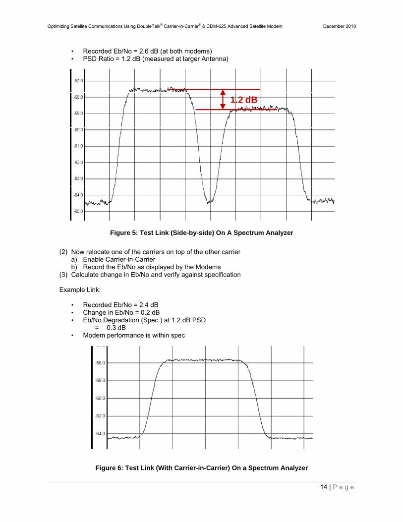
• Recorded Eb/No = 2.6 dB (at both modems) • PSD Ratio = 1.2 dB (measured at larger Antenna)
Figure 5: Test Link (Side-by-side) On A Spectrum Analyzer
(2) Now relocate one of the carriers on top of the other carrier
a) Enable Carrier-in-Carrier b) Record the Eb/No as displayed by the Modems
(3) Calculate change in Eb/No and verify against specification
Example Link:
• Recorded Eb/No = 2.4 dB • Change in Eb/No = 0.2 dB • Eb/No Degradation (Spec.) at 1.2 dB PSD
= 0.3 dB • Modem performance is within spec
Figure 6: Test Link (With Carrier-in-Carrier) On a Spectrum Analyzer
1.2 dB
Optimizing Satellite Communications Using DoubleTalk® Carrier-in-Carrier® & CDM-625 Advanced Satellite Modem December 2010
15 | P a g e
Carrier-in-Carrier Latency
Carrier-in-Carrier has no measurable impact on circuit latency.
Carrier-in-Carrier and Adaptive Coding and Modulation (ACM)
Carrier-in-Carrier is fully compatible with VersaFEC Adaptive Coding and Modulation (ACM) mode of operation in CDM-625. Carrier-in-Carrier combined with VersaFEC ACM can provide 100 – 200% increase in average throughput.
Carrier-in-Carrier and Automatic Uplink Power Control (AUPC)
AUPC can be used with Carrier-in-Carrier to compensate for rain fade or other dynamic fade. However, the maximum transmit power level change is limited to 3 dB.
Summary
Comtech EF Data’s DoubleTalk Carrier-in-Carrier can provide significant savings in operational expenses. The following should be considered when evaluating DoubleTalk Carrier-in-Carrier:
DoubleTalk Carrier-in-Carrier can only be used for full duplex links where the transmitting earth station is able to receive itself.
DoubleTalk Carrier-in-Carrier can be used in bandwidth limited, power limited or bandwidth and power limited situations
The maximum savings is generally achieved when the original link is symmetric in data rate
Appendix
Carrier-in-Carrier Link Budget Calculation
Following steps are involved in calculating the link budget for a Carrier-in-Carrier link:
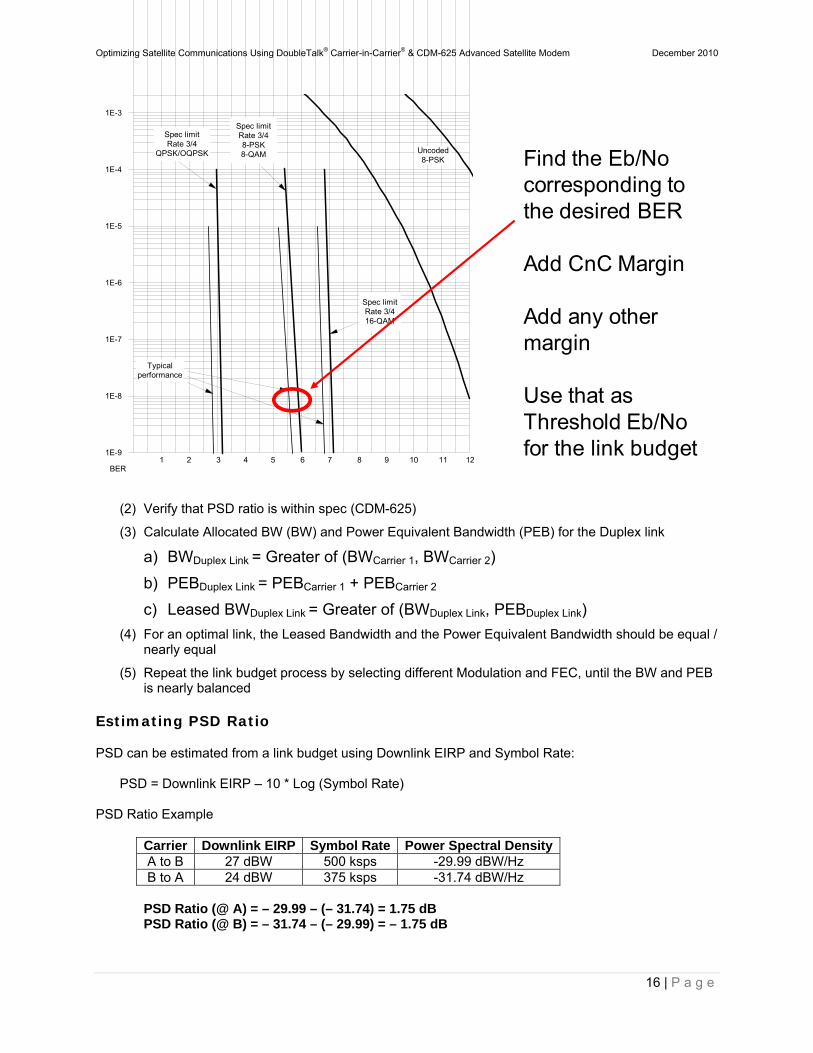
(1) Calculate the link budget for each individual carrier in the duplex link, with required CnC margin
Optimizing Satellite Communications Using DoubleTalk® Carrier-in-Carrier® & CDM-625 Advanced Satellite Modem December 2010
16 | P a g e
(2) Verify that PSD ratio is within spec (CDM-625)
(3) Calculate Allocated BW (BW) and Power Equivalent Bandwidth (PEB) for the Duplex link
a) BWDuplex Link = Greater of (BWCarrier 1, BWCarrier 2)
b) PEBDuplex Link = PEBCarrier 1 + PEBCarrier 2
c) Leased BWDuplex Link = Greater of (BWDuplex Link, PEBDuplex Link)
(4) For an optimal link, the Leased Bandwidth and the Power Equivalent Bandwidth should be equal / nearly equal
(5) Repeat the link budget process by selecting different Modulation and FEC, until the BW and PEB is nearly balanced
Estimating PSD Ratio
PSD can be estimated from a link budget using Downlink EIRP and Symbol Rate:
PSD = Downlink EIRP – 10 * Log (Symbol Rate)
PSD Ratio Example
Carrier Downlink EIRP Symbol Rate Power Spectral DensityA to B 27 dBW 500 ksps -29.99 dBW/Hz B to A 24 dBW 375 ksps -31.74 dBW/Hz
PSD Ratio (@ A) = – 29.99 – (– 31.74) = 1.75 dB PSD Ratio (@ B) = – 31.74 – (– 29.99) = – 1.75 dB
1E-9
1E-8
1E-7
1E-6
1E-5
1E-4
1E-3
1 2 3 4 5 6 7 8 9 10 11 12BER
Spec limitRate 3/416-QAM
Spec limitRate 3/4
QPSK/OQPSK
Typicalperformance
Uncoded8-PSK
Spec limitRate 3/48-PSK8-QAM Find the Eb/No
corresponding to the desired BER
Add CnC Margin
Add any other margin
Use that as Threshold Eb/No for the link budget
Optimizing Satellite Communications Using DoubleTalk® Carrier-in-Carrier® & CDM-625 Advanced Satellite Modem December 2010
17 | P a g e
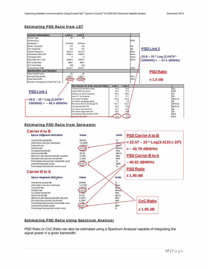
Estimating PSD Ratio from LST
Estimating PSD Ratio from Satmaster
Estimating PSD Ratio Using Spectrum Analyzer PSD Ratio or CnC Ratio can also be estimated using a Spectrum Analyzer capable of integrating the signal power in a given bandwidth.
Carrier Information Link 1 Link 2 Carrier Type IPL IPLPerformance BERModulation 8-Phase 8-Phase
Eb/No Threshold 5.6 5.6 dBC/N Threshold 8.6 8.6 dB
Center Frequency 6014.0 6014.0 MHzInformation Rate (IR) 4096.0 4096.0 kbit/sOverhead (OH) .0 .0 kbit/sData Rate (IR + OH) 4096.0 4096.0 kbit/s
FEC Code Rate .6667 .6667 R-S Code Rate N/A N/ATransmission Rate 6143.7 6143.7 kbit/s
Bandwidths and MarginsFilter Rolloff Factor .40 .40 Allocated Bandwidth 2.8671 2.8671 MHzNoise Bandwidth 2.0479 2.0479 MHz
Number of Assigned Carriers Per Link 1 1
Per Carrier UL & DL eirp (Clr-Sky) Link 1 Link 2 Transmit ES elevation angle 70.4 54.5 deg.Uplink EIRP per carrier 58.7 57.0 dBW
Pathloss at uplink frequency 199.3 199.5 dB Gain of 1 m2 antenna 37.1 37.1 dBi
Per carrier FD @SC -103.5 -105.4 dBW/m2 SC pattern advantage @ES 1.8 2.8 dB Per carrier BE FD arriving @ SC -101.7 -102.7 dBW/m2
Transponder BE SFD -79.0 -79.0 dBW/m2
Per carrier input back-off -22.7 -23.7 dB Per carrier output back-off -20.2 -21.2 dB Transponder BE saturation EIRP 37.0 37.0 dBW
Downlink BE EIRP 16.8 15.8 dBW
PSD Link 1
16.8 – 10 * Log (2.0479 * 1000000) = – 46.3 dBW/Hz
PSD Link 2
15.8 – 10 * Log (2.0479 * 1000000) = – 47.3 dBW/Hz
PSD Ratio
± 1.0 dB
Carrier A to B
Carrier B to A
CnC Ratio
± 1.95 dB
PSD Carrier A to B
= 22.57 – 10 * Log(3.4133 x 10⁶)
= – 42.76 dBW/Hz
PSD Carrier B to A
– 40.81 dBW/Hz
PSD Ratio
± 1.95 dB
Optimizing Satellite Communications Using DoubleTalk® Carrier-in-Carrier® & CDM-625 Advanced Satellite Modem December 2010
18 | P a g e
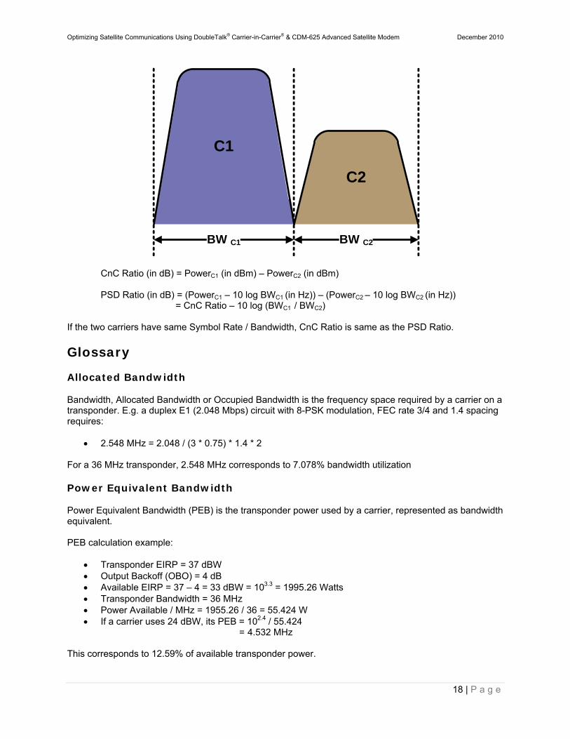
CnC Ratio (in dB) = PowerC1 (in dBm) – PowerC2 (in dBm) PSD Ratio (in dB) = (PowerC1 – 10 log BWC1 (in Hz)) – (PowerC2 – 10 log BWC2 (in Hz))
= CnC Ratio – 10 log (BWC1 / BWC2) If the two carriers have same Symbol Rate / Bandwidth, CnC Ratio is same as the PSD Ratio.
Glossary
Allocated Bandwidth
Bandwidth, Allocated Bandwidth or Occupied Bandwidth is the frequency space required by a carrier on a transponder. E.g. a duplex E1 (2.048 Mbps) circuit with 8-PSK modulation, FEC rate 3/4 and 1.4 spacing requires:
2.548 MHz = 2.048 / (3 * 0.75) * 1.4 * 2 For a 36 MHz transponder, 2.548 MHz corresponds to 7.078% bandwidth utilization
Power Equivalent Bandwidth
Power Equivalent Bandwidth (PEB) is the transponder power used by a carrier, represented as bandwidth equivalent. PEB calculation example:
Transponder EIRP = 37 dBW Output Backoff (OBO) = 4 dB Available EIRP = 37 – 4 = 33 dBW = 103.3 = 1995.26 Watts Transponder Bandwidth = 36 MHz Power Available / MHz = 1955.26 / 36 = 55.424 W If a carrier uses 24 dBW, its PEB = 102.4 / 55.424
= 4.532 MHz This corresponds to 12.59% of available transponder power.
C2
C1
BW C1 BW C2
Optimizing Satellite Communications Using DoubleTalk® Carrier-in-Carrier® & CDM-625 Advanced Satellite Modem December 2010
19 | P a g e
Leased Bandwidth
Almost all satellite operators charge for the Leased Bandwidth (LBW). Leased Bandwidth or Leased Resource is the greater of the Allocated Bandwidth and Power Equivalent Bandwidth. E.g. if a carrier requires 3 MHz of Allocated BW and 4.5 MHz of PEB, the Leased Bandwidth is 4.5 MHz
Power Spectral Density (PSD)
Power Spectral Density (PSD) is the signal power per unit bandwidth dBW / Hz or dBm / Hz
Example
Signal power = 20 dBm Signal bandwidth = 500 kHz PSD = 20 – 10 *log (500 * 1000)
= – 36.99 dBm / Hz
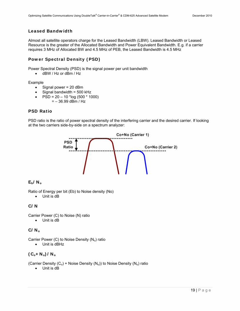
PSD Ratio
PSD ratio is the ratio of power spectral density of the interfering carrier and the desired carrier. If looking at the two carriers side-by-side on a spectrum analyzer:
Eb/No
Ratio of Energy per bit (Eb) to Noise density (No) Unit is dB
C/N
Carrier Power (C) to Noise (N) ratio Unit is dB
C/No
Carrier Power (C) to Noise Density (No) ratio Unit is dBHz
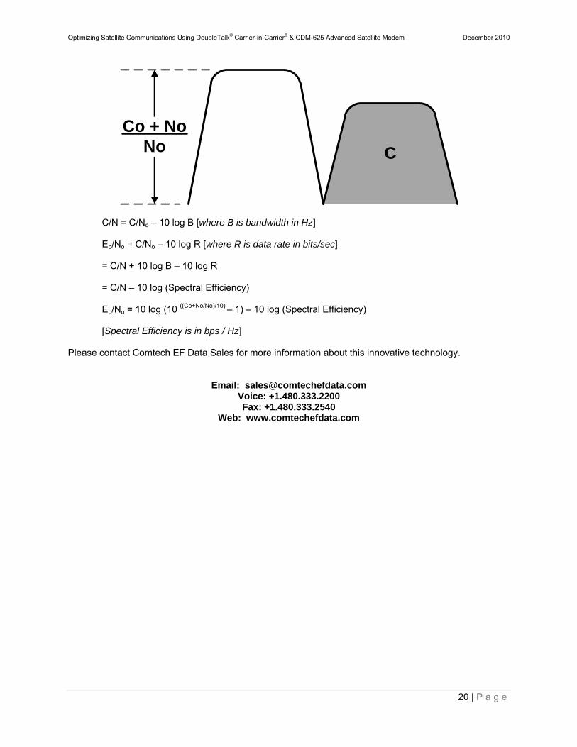
(Co+No)/No
(Carrier Density (Co) + Noise Density (No)) to Noise Density (No) ratio Unit is dB
Optimizing Satellite Communications Using DoubleTalk® Carrier-in-Carrier® & CDM-625 Advanced Satellite Modem December 2010
20 | P a g e
C/N = C/No – 10 log B [where B is bandwidth in Hz] Eb/No = C/No – 10 log R [where R is data rate in bits/sec] = C/N + 10 log B – 10 log R = C/N – 10 log (Spectral Efficiency) Eb/No = 10 log (10 ((Co+No/No)/10) – 1) – 10 log (Spectral Efficiency) [Spectral Efficiency is in bps / Hz]
Please contact Comtech EF Data Sales for more information about this innovative technology.
Email: [email protected] Voice: +1.480.333.2200 Fax: +1.480.333.2540
Web: www.comtechefdata.com
Co + NoNo C