OPTIMIZING RECEIVERS FOR GROUND BASED MM …lss.fnal.gov/archive/other1/iram-492.pdf ·...
7
OPTIMIZING RECEIVERS FOR GROUND BASED MM-WAVE RADIO TELESCOPES A. Karpov IRAM N°492 Proc. ESA Workshop on MM-Wave Techn. f3 Applic. 1998
Transcript of OPTIMIZING RECEIVERS FOR GROUND BASED MM …lss.fnal.gov/archive/other1/iram-492.pdf ·...
OPTIMIZING RECEIVERS FOR GROUND BASED MM-WAVE
RADIO TELESCOPES
A. Karpov
IRAM N°492
Proc. ESA Workshop on MM-Wave Techn. f3 Applic.
1998

Invited talk. Proceedings ofthe 2th ESA Workshop on Millimeter Wave Technology and Applications, lRAM technical report 250/98
Optimizing receivers for ground based mm wave radio telescopes
A.Kmpov v
Institut de Radioastronomie Millimetrique, 300. rue de la Piscine. Domaine Universitaire de Grenoble, F:.-38406 St MaiIDi-cmeres,J:rance
-----_.~
ABSTRACT
We present a study of requirements on the sensitivity of mm and sub millimeter wave receivers for application in radio astronomy. The study is based on the experience of the operation of the SIS receivers at the radio telescopes of IRAM and considers also the conditions of operation at the future radioastronomical instruments such as LSA. MMA and LMSA. Using a radio telescope and atmospheric model we consider the effect of the receiver sensitivity on the radio telescope operation in terms of observing time. The observing time at a radio telescope depends on the system noise temperature as strongly as on collecting area. which defines nearly all the cost of modern mm and sub mm instruments. As a compromise between the receiver development effort and the system performance we introduce a criterion of an "optimum" receiver noise. A strict requirement on the receiver operation is obtained. For an efficient use of the existing and the future radio telescopes. a 10 - 20 K SSB receiver noise in the mm band and 20-40 K SSB at sub millimeter wavelength are necessary. Finally the status of development of SIS receiver for mm and sum mm radio astronomy is presented.
Keywords: low noise receivers, radio telescope, millimeter wave. SIS receiver.
1. INTRODUCTION
Radio astronomy is a domain where the most sensitive millimeter wave receivers are required [1.2]. The performance of the receivers in millimeter wave radio astronomy is based on development of low noise. broad band and stable SIS mixers [1.2]. Having as a basic limitation only the quantum noise limit of hulk. for the SSB noise temperature they may remain as the basis for the construction of new observing facilities. The inconveniences such as the cooling to the liquid helium temperature and sometimes the mechanical tuning for SSB operation remain less important compared to the strict requirement on the receiver sensitivity for an efficient use of the radio telescopes. impossible with other types of receiver.
A further development of millimeter wave radio astronomy instrumentation is related to the construction of the big interferometers such as the Large Southern Array (LSA)[3]. Millimeter Array (MMA)[3], or Large Millimeter and Submillimeter Array (LMSA)[4] planned to integrate 50-60 antennas of 10-15 m in diameter at the high altitude plateau in Chile, at about 5 kIn of elevation. The new instruments will have a collecting area more than 10-20 time larger than in existing instruments such as the IRAM radio interferometer [6].
In preparing such new instruments for mm and submillimeter wave radio astronomy an important work on the receiver development has to be undertake. One can put forward once more a question about an optimum design of the receivers for these instruments and about their role in the system performance for the existing context of receiver and telescope technology and for the future.
As a starting point for a discussion one can use an example the case of existing radio interferometers, such as the !RAM five 15 meter antenna interferometer in the French Alps at 2500 m altitude. The IRAM radio interferometer at the Plateau de Bure (PdB) is an instrument with the biggest collecting area developed for the radio astronomy observations around 1 mm wavelength [6]. We are using the PdB radio telescopes data as an example of a modern instrument for an estimation of the role of the receivers in the existent context. First we give a presentation of the requirements on the receivers for the IRAM installations based at our IRAM internal report [7]. Then we study the requirements on the receiver sensitivity for the future instruments and present the status of the SIS receiver development in IRAM.

Invited talk. Proceedings ofthe 2th ESA Workshop on Millimeter Wave Technology and Applications, IRAM technical report 250198
2. OPTIMUM NOISE RECEIVERS FOR IRAM RADIO TELESCOPES
The reduction of the receiver noise always reduces the integration time required for an observation. Nevertheless some reasonable minimum of the receiver noise may be evaluated. The requirement on the sensitivity of a receiver may be formulated in terms of the optimization of the radio telescope system performance, including the receiver, the telescope and the atmosphere. As an optimization criterion we can use the relative speed-up of observations at a telescope versus receiver temperature. As a reference value, not affected by the receiver operation, we take the observation time necessary for detection of a certain signal with the same telescope in a hypothetical situation of zero receiver noise. The relative variation of integration time is estimated from the relative variation of the system noise temperature:
(1)
An acceptable increase in observation time has to serve as a compromise between the receiver development effort and the system performance. One can use a 50 % increase in observation time, not negligible indeed, as a criterion for the estimation of the optimum receiver noise for radio telescopes.
The system noise temperature T*Sys is calculated according to [8]:
* _ 1+ G; I Gs [F T ]T S)'s - eft • .LSky +(1- Feft)' TAmb + TRee (2)F:ff exp(- A 1"0)
where T*sys is the radio telescope system noise temperature at the "star scale" in a reference plane out of the atmosphere; Tsky, Tamb and Trec are respectively the sky antenna temperature, the ambient temperature and the receiver noise temperature; Gs and Gi are respectively the signal and image band conversion gain, Felf is the forward efficiency; 'to is the sky zenith opacity.
The sky antenna temperature Tsky is calculated as: I'sky =TAtm • [1- exp(-A1"0)]
where the airmass A is: A =~() and <X is the telescope elevation angle. Comparing (1) and (2) one can SIn a
mention that the speed-up of observation (1) does not depend on the sideband ratio Gs/Gi , but only on the value of Trec. So, the requirements on the value of receiver noise listed below concern equally observations with a Double Sideband receiver (Tree DSB) or with Single Sideband receivers (Trec SSB). As the major part of most observations is in SSB mode, we will discuss especially the requirements on Trec SSB.
We selected the different typical frequencies as 90, 230, and 345 GHz and proceed our calculations for several different atmospheric conditions. We studied "good" summer weather (7 mm Precipitable Water Vapor (PWV», the "average" winter/good summer conditions (4 mm PWV) and "good" winter weather (2 mm the PWV). At 345 GHz we consider also an "excellent" winter weather (0.5 mm PWV). This estimation concerns both the IRAM Plateau de Bure Interferometer and the 30 m IRAM Pico Veleta (PV) telescope for the following reasons. The forward efficiencies of the two types of antennas are the same within 1%, at least in the 3 mm (90%) and 1.3 mm bands (86 %). The estimation at 345 GHz concerns first the 30 m radio telescope with a 75% forward efficiency. The typical values of the atmospheric opacity are also similar at the two sites [9].
An example for a frequency of 90 GHz is shown in the figure 1. Here the relative fraction of the system noise due to a non zero receiver noise {T*sys(Trec)-T*sys(Trec=O)}ff*sys(Trec) is plotted against Trec at the left. First we can say that the receiver noise gives a significant part of the system noise and the receiver noise may easily dominate in the system operation.
We obtain a more clear presentation of the receiver noise role by estimating the time required for the detection of an astronomical signal, determining the number of the astronomical project one can schedule at the telescope. In the right part of the figure 1 is plotted the relative increase of the radio telescope observation time (1) versus the receiver noise. One can see that in typical weather the observation time of a modem radio telescope strongly depends on the receiver noise. With a moderate 50 K receiver noise the observation time has to be 4 time longer, than the minimum at a zero receiver noise. This corresponds to the loss of a half of the radio telescope collecting area, or, what is nearly the same, the loss of the half of the funding for a radio telescope. Only by approaching an "o.p~imum" TRec OpFI0 K receiver noise one can achieve an observation time only 50% longer than the mInimum.

Invited talk. Proceedings o/the 2th ESA Workshop on Millimeter Wave Technology and Applications, IRAM technical report 250198
This "optimum" receiver noise of 10 K SSB required at 90 GHz for the existing radio telescopes is far better the best published results of 60 K SSB of an SIS receiver at NRAO Keat Peak radio telescope [10]. In our recent SIS receiver prepared for installation at the PdB interferometer the SSB receiver noise ranges between 30 K and 48 K in the 80-120 GHz band (figure 6).
The estimation of observation speed-up versus receiver noise is plotted in the figure 2 for frequencies of 230 GHz and 345 GHz. In this typical condition even with a bigger atmospheric opacity the time required for the detection of an astronomical signal strongly depends on the receiver noise. The 150% threshold compared to the minimum observation time can only reached with a 20 K SSB receiver noise at 230 GHz and 30 K SSB at 345 GHz. For the moment the best 8SB receiver noise at these frequencies is about 50 K (figure 6).
10
~ u'0 E 8Z 0.8
E= ~ I:
>. ·i0
CI)
0.6 t: 6.9 u I: '" 0 8.~
u.rJ oS'C 40.4 ...E 00 uu :at e> .~ 0.2 .5
u
~ CG
o 0 00 40 60 80 100
Receiver Noise Temperature [K] Receiver Noise Temperature [K]
Figure 1. The contribution of a receiver to a modern mm wave radio telescope system noise temperature (left) and the influence of the receiver noise at the time of observation (right) at 90 GHz. We are using an example of the IRAM 30 m radio telescope at Pico Veleta or IRAM 15 m radio telescopes of the Plateau de Bure interferometer. The antenna is at 45° elevation, forward efficiency is 92% and the altitude is 2500-2800 m. A solid line represents an average summer weather (7 mm PWV), a dotted line - a good summer/average winter weather with 4 mm PWV and a dashed line - a good winter weather with 2 mm PWV. In a typical weather the mm wave receiver noise may easily dominate the operation of a modern radio telescope and to increase strongly the observation time. With a 10 K receiver noise a time required for an observation is still longer than the minimum by 50%.
5 r---~----.--..,..---~,~-~-, 5r-----.----,---~--y~--...,
4··..·· · ·
2-~:j::;;.4~----t--+-
, I
! ,
1 ,;,
_+ ·..· +,.
3 1-....--+--I----+.=---/-...J.+---+---1 . I"
~" I 1 1 rr---j----+---+-----+---f
o 0 o 040 80 120 160 200 40 80 120 160 200
230 GHz Receiver Noise Temperature [K] 350 GHz Receiver Noise Temperature [K]
Figure 2. Estimation of a relative increase of the radio telescope observation time at 230 GHz (left) and 350 GHz (right). The Forward efficiency at 230 GHz is 86% and 75% at 350 GHz. The conditions are the same as in the figure. For the 350 GHz data we add an estimation in "excellent" winter weather with 0.5 mm PWV (dotteddashed line). In a good weather, when the observations are the most rapid, the observation time strongly depends on the receiver sensitivity, until we reach a 20 K receiver noise at 230 GHz and 30 K at 350 GHz.

Invited talk. Proceedings ofthe 2th ESA Workshop on Millimeter Wave Technology and Applications, IRAM technical report 250198
3. RECEIVER FOR THE LSAIMMA SITE OBSERVING CONDITIONS
At about 5000 m altitude at a new site studied for the LSAlMMAlLSMA projects the weather is much better than at the existing radio telescope locations. Here the PWV below 0.5 mm is observed about 25-30 % of the time ("good" weather) and for about 75% of the time the PWV is below 1.5 mm ("average" weather) [4,11]. For comparison at the IRAM radio telescopes only in "good" winter time weather the is PWV below 1.5 mm for about 25% of the time and below 5 mm 75% of the time in "average" weather. In these new conditions the requirements on the receiver sensitivity are even more severe and demand further progress in sensitivity.
The transmission through the atmosphere with 0.5 mm, 1.5 mm and 5 mm PWV is plotted with the typical values of the forward efficiency FEffexisting at IRAM radio telescopes in the figure 3. The loss in the radio telescope (FEff) is a minor contribution in the total loss at the IRAM radio telescopes in "average" weather with 5 mm PW'V, and gives just half of the total loss in "good" weather. At the new site this level of the loss will dominate loss in the atmosphere and can not to be accepted.
One can expect that with progress in technology FEft will be increased up to the maximum existing now at 100 GHz, of about 92%. Below we will use this value for the estimations for a 60 GHz - 550 GHz frequency range.
Frequency [GHz]
Figure 3. The atmospheric transmission with 0.5 mm, 1.5 rom, and 5 mm PWV (from upper to lower curve) and the forward efficiency at the IRAM 30 m radio telescope. The PWV level is below 1.5 mm at the 30 m telescope site about 25% of winter time, and about 75% of the winter time below 5 rom PWV. At the LSA site the PWV is below 0.5 mm during the 25% of observing time and below 1.5 mm PWV during 75 % of the time. At the existing radio telescope the loss related to the forward efficiency is not dominating the atmospheric loss, but at the LSA site the forward efficiency may be the main limiting factor of the system sensitivity.
The "optimum" receiver noise TRec Opt required for the atmospheric conditions of figure 3 is summarized in the figure 4. Here we are using for TRee Opt the relation (3) obtained from (1) and (2) for a relative increase of observation time tlto=l.5.
TRecOPt =(.J[5 -1)(~ff~ky +(1- FEff )~mb) (3)
The"optimum" receiver noise depends on the forward efficiency, and through the sky antenna temperature on the zenith opacity. For a fixed FEffthe minimum TRee Opt required with a zero zenith opacity is:
Min(TRecOPt) =(.J[5 -1)(1- FEff)~mb' (4)
about 6 K with FEJF92%. Under the same conditions the maximum of the TRee Opt corresponds to an important atmosphenc opacity, and is about 60 K, independent of the frequency:
Max(TRecOpt) =(.J[5 -l){~mb - FEff{TAnzh - TAtm )) (5)
Invited talk. Proceedings o/the 2th ESA Workshop on Millimeter Wave Technology and Applications, IRAM technical report 250/98
60
lIol 50 OS fIJ
Z g'" lIol 40 ~ lIol
'S '" u :sell 30 -lIol
~ '" e =:se e 20lIol ~E-!
8 10
o so
/7l\T',, I 1\
i--" :"1' ' . ~.. ,.- 7' .'.'
IJ ......... · ,,
/ " V·· ·· · u
I ...· ,
n -, VlJ\
, .:J, ,
Jf : ,~ .. ' f \ v
:.:.:::--~,· ) I----\ -
\'-. .'
~ -1 IrfJc1'-"'" : \~, _..~
" ~ -.' l ~
----100 150 200 250 300 350 400 450 500 550
Frequency [GHz]
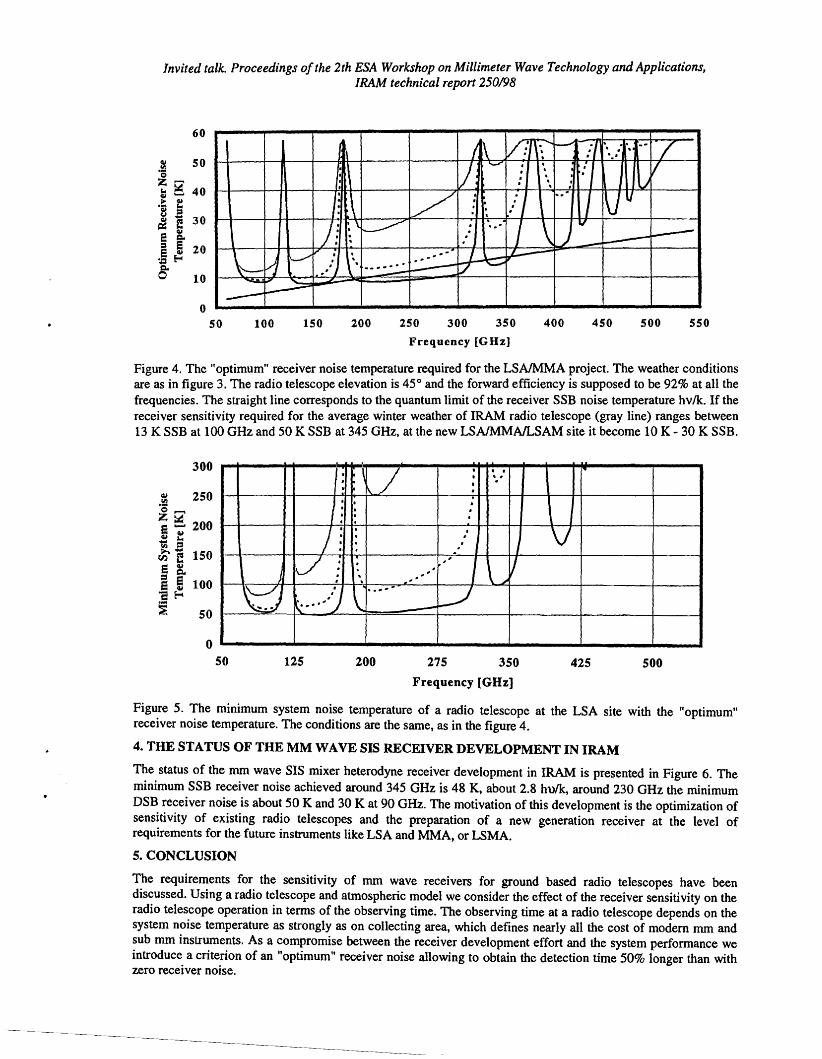
Figure 4. The "optimum" receiver noise temperature required for the LSAIMMA project. The weather conditions are as in figure 3. The radio telescope elevation is 45° and the forward efficiency is supposed to be 92% at all the frequencies. The straight line corresponds to the quantum limit of the receiver SSB noise temperature hvlk. If the receiver sensitivity required for the average winter weather of lRAM radio telescope (gray line) ranges between 13 K SSB at 100 GHz and 50 K SSB at 345 GHz. at the new LSAlMMAlLSAM site it become 10 K - 30 K SSB.
300
.; 250 0 ...... · Z~ · e ...... 200 ~ ~ .." II) ='
,..£ e 150 e lIol ..=' Co e ! 100 '8 ~ L-,J~ 50
, \~J,
· ,,·I · ,
,
I~ ..,
IJ I I'. I
, .,; ,. ,
~ . .. -," ..
. ,<J \I'·' o
· .. · , . · · · \
V J
V1 \ ""
50 125 200 275 350 425 500 Frequency [GHz]
Figure 5. The minimum system noise temperature of a radio telescope at the LSA site with the "optimum" receiver noise temperature. The conditions are the same, as in the figure 4.
4. THE STATUS OF THE MM WAVE SIS RECEIVER DEVELOPMENT IN IRAM
The status of the mm wave SIS mixer heterodyne receiver development in IRAM is presented in Figure 6. The minimum SSB receiver noise achieved around 345 GHz is 48 K, about 2.8 hulk, around 230 GHz the minimum DSB receiver noise is about 50 K and 30 K at 90 GHz. The motivation of this development is the optimization of sensitivity of existing radio telescopes and the preparation of a new generation receiver at the level of requirements for the future instruments like LSA and MMA, or LSMA.
5. CONCLUSION
The requirements for the sensitivity of mm wave receivers for ground based radio telescopes have been discussed. Using a radio telescope and atmospheric model we consider the effect of the receiver sensitivity on the radio telescope operation in terms of the observing time. The observing time at a radio telescope depends on the system noise temperature as strongly as on collecting area, which defines nearly all the cost of modem mm and sub mm instruments. As a compromise between the receiver development effort and the system performance we introduce a criterion of an "optimum" receiver noise allowing to obtain the detection time 50% longer than with zero receiver noise.
Invited talk. Proceedings o/the 2th ESA Workshop on Millimeter Wave Technology and Applications. IRAM technical report 250198
Applying the criteria of an "?ptimu~" receiver noise to the typical conditions of the existing mm wave radio telescopes, one need the receivers with the to-20K SSB noise in the mm band, and the 30-40 K in the submm band. For the futures radio telescopes the requirements are more strict, and become 10 K SSB in the mm band and 15-40 K at the submm wavelength.
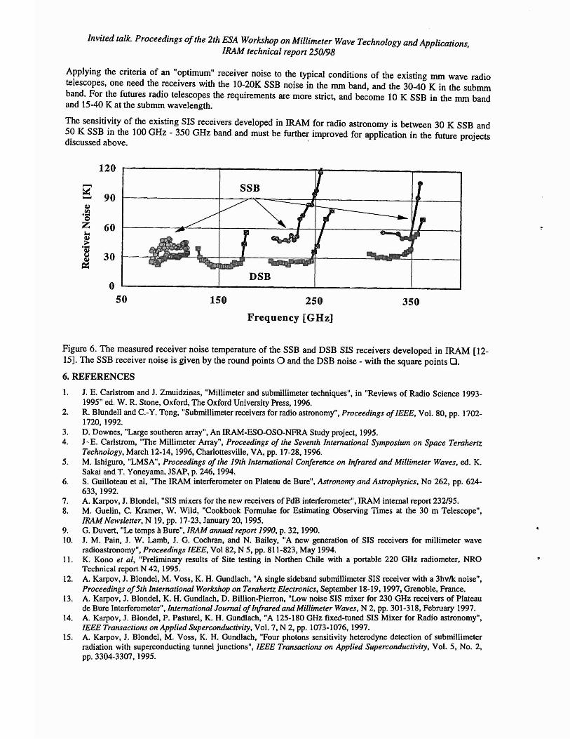
The sensitivity of the existing SIS receivers developed in IRAM for radio astronomy is between 30 K SSB and 5? K SSB in the 100 GHz - 350 GHz band and must be further improved for application in the future projects discussed above. .
120
...... ~
90...... Cl.l III... 0 Z 60 '"' ~... Cl.l
~ 30
DSB 0
50 150 250 350
Frequency [GHz]
Figure 6. The measured receiver noise temperature of the SSB and DSB SIS receivers developed in IRAM [1215]. The SSB receiver noise is given by the round points 0 and the DSB noise - with the square points O.
6. REFERENCES
1. J. E. Carlstrom and 1. Zmuidzinas. "Millimeter and submiIlimeter techniques". in "Reviews of Radio Science 19931995" ed. W. R. Stone, Oxford. The Oxford University Press, 1996.
2. R. Blundell and C.-Y. Tong, "Submillimeter receivers for radio astronomy", Proceedings of IEEE, Vol. 80. pp. 17021720,1992.
3. D. Downes, "Large southeren array". An IRAM-ESO-OSO-NFRA Study project. 1995. 4. J~E. Carlstrom, "The Millimeter Array", Proceedings of the Seventh International Symposium on Space Terahertz
Technology, March 12-14, 1996, Charlottesville, VA, pp. 17-28.1996. 5. M. Ishiguro, "LMSA", Proceedings of the 19th International Conference on Infrared and Millimeter Waves, ed. K.
Sakai and T. Yoneyama, JSAP, p. 246,1994. 6. S. Guilloteau et ai, 'The IRAM interferometer on Plateau de Bure", Astronomy and Astrophysics, No 262, pp. 624
633.1992. 7. A. Karpov, J. Blondel, "SIS mixers for the new receivers ofPdB interferometer", IRAM internal report 232/95. 8. M. Guelin, C. Kramer, W. Wild, "Cookbook Formulae for Estimating Observing Times at the 30 m Telescope",
lRAM Newsletter, N 19, pp. 17-23, January 20,1995. 9. G. Duvert, "Le temps aBure", lRAM annual report 1990, p. 32, 1990. 10. J. M. Pain, J. W. Lamb, J. G. Cochran, and N. Bailey, "A new generation of SIS receivers for millimeter wave
radioastronomy", Proceedings IEEE, Vo182, N 5, pp. 811-823, May 1994. 11. K. Kono et aI, "Preliminary results of Site testing in Northen Chile with a portable 220 GHz radiometer, NRO
Technical report N 42, 1995. 12. A. Karpov, J. Blondel, M. Voss, K. H. Gundlach, "A single sideband submiIlimeter SIS receiver with a 3hv!k noise",
Proceedings of5th International Workshop on Terahertz Electronics, September 18-19, 1997, Grenoble, France. 13. A. Karpov, J. Blondel, K. H. Gundlach, D. Billion-Pierron, "Low noise SIS mixer for 230 GHz receivers of Plateau
de Bure Interferometer",lnternational Journal ofInfrared and Millimeter Waves. N 2, pp. 301-318, February 1997. 14. A. Karpov, J. Blondel. P. Pasturel. K. H. Gundlach, "A 125-180 GHz fixed-tuned SIS Mixer for Radio astronomy",
IEEE Transactions on Applied Superconductivity, Vol. 7. N 2. pp. 1073-1076, 1997. 15. A. Karpov, J. Blondel, M. Voss, K. H. Gundlach, "Four photons sensitivity heterodyne detection of submilIimeter
radiation with superconducting tunnel junctions", IEEE Transactions on Applied Superconductivity, Vol. 5, No.2. pp. 3304-3307, 1995.