Optimizing Locomotion Controllers Using Biologically-Based...
11
ACM Reference Format Wang, J., Hamner, S., Delp, S., Koltun, V. 2012. Optimizing Locomotion Controllers Using Biologically- Based Actuators and Objectives. ACM Trans. Graph. 31 4, Article 25 (July 2012), 11 pages. DOI = 10.1145/2185520.2185521 http://doi.acm.org/10.1145/2185520.2185521. Copyright Notice Permission to make digital or hard copies of part or all of this work for personal or classroom use is granted without fee provided that copies are not made or distributed for profit or direct commercial advantage and that copies show this notice on the first page or initial screen of a display along with the full citation. Copyrights for components of this work owned by others than ACM must be honored. Abstracting with credit is permitted. To copy otherwise, to republish, to post on servers, to redistribute to lists, or to use any component of this work in other works requires prior specific permission and/or a fee. Permissions may be requested from Publications Dept., ACM, Inc., 2 Penn Plaza, Suite 701, New York, NY 10121-0701, fax +1 (212) 869-0481, or [email protected]. © 2012 ACM 0730-0301/2012/08-ART25 $15.00 DOI 10.1145/2185520.2185521 http://doi.acm.org/10.1145/2185520.2185521 Optimizing Locomotion Controllers Using Biologically-Based Actuators and Objectives Jack M. Wang Samuel R. Hamner Scott L. Delp Vladlen Koltun Stanford University Abstract We present a technique for automatically synthesizing walking and running controllers for physically-simulated 3D humanoid charac- ters. The sagittal hip, knee, and ankle degrees-of-freedom are ac- tuated using a set of eight Hill-type musculotendon models in each leg, with biologically-motivated control laws. The parameters of these control laws are set by an optimization procedure that satis- fies a number of locomotion task terms while minimizing a biolog- ical model of metabolic energy expenditure. We show that the use of biologically-based actuators and objectives measurably increases the realism of gaits generated by locomotion controllers that operate without the use of motion capture data, and that metabolic energy expenditure provides a simple and unifying measurement of effort that can be used for both walking and running control optimization. CR Categories: I.3.7 [Computer Graphics]: Three-Dimensional Graphics and Realism—Animation; Keywords: physics-based character animation, biomechanics, musculoskeletal simulation Links: DL PDF 1 Introduction The development of physics-based locomotion controllers de novo, independent from stock motion data, has been a long-standing ob- jective in computer graphics research and has seen resurgence in recent years. Despite impressive progress, the gaits produced by existing controllers fall short of the natural appearance of human locomotion. For example, physics-based walking controllers that do not rely on motion capture data commonly produce walking mo- tion with exaggerated hip flexion which appears more crouched and less fluid than typical human walking. One likely cause of these differences is the control force genera- tion mechanism. Biological control systems output neural excita- tion signals, which then generate musculotendon forces that lead to joint torques. The mapping from excitation to torque is highly complex due to variable moment arms, biarticular muscles, and the dependence of musculotendon forces on fiber length and con- traction velocity [Zajac 1989]. On the other hand, state-of-the-art bipedal locomotion control methods directly output joint torques, which ignore constraints and energetic costs imposed by muscle anatomy and physiology. Consequently, to accomplish a motion task, controllers often employ torque patterns that are inefficient or even impossible for humans. These biologically implausible torque patterns diminish the naturalness of the resulting gaits. The goal of our work is to enhance the realism of locomotion gaits exhibited by physically-simulated humanoids without depen- dence on motion capture data. To this end, we augment the joint- actuated humanoid model with a set of Hill-type musculotendon units (MTUs). These musculotendon units generate torques for the most important degrees-of-freedom (DOFs) during locomotion— the sagittal plane hip, knee, and ankle DOFs. To actuate these mus- cles, we define biologically-motivated control functions that map the current state of the body (joint angles, muscle fiber lengths, etc.) to excitation signals. The parameters of these functions are optimized to yield gaits that move the character forward without falling down. While many sets of parameters are capable of achieving this task, the quality of the resulting motion varies significantly among them. To produce gaits that have a high degree of realism, we employ an objective based on minimization of metabolic energy expendi- ture, thus choosing the most effortless gait that achieves the task [Alexander 2003]. In living humans and animals, metabolic en- ergy expenditure can be estimated by oxygen consumption. In contrast, it is less clear how metabolic energy expenditure should be modeled for simulated characters. A common substitute is the sum of squared joint torques [Schultz and Mombaur 2010], which does not account for the different effort levels required to gen- erate torques in different joints, directions, and body configura- tions. More nuanced objectives can be learned from inverse op- timization [Liu et al. 2005], but are dependent on training data. Our use of biologically-based actuators enables the estimation of metabolic energy expenditure based on the internal state of the MTUs [Anderson 1999]. The result is a locomotion control opti- mization procedure that minimizes a physiologically-based objec- tive within a parameter space restricted to biologically plausible torque patterns. We demonstrate the presented approach by optimizing locomotion controllers for a wide range of speeds. For quantitative evaluation, we collected experimental ground truth data from 20 human sub- jects walking and running at eight speeds on an instrumented tread- mill. Much like human locomotion, our controllers utilize signif- icant ankle torque and generate smooth torque trajectories. The resulting gaits match human ground truth to a greater extent than state-of-the-art walking controllers that do not rely on motion cap- ture data. Furthermore, we show that by simply changing the initial- ization and target velocity, the same optimization procedure leads to running controllers. 2 Related Work Animation researchers have been interested in the control of locomotion for 3D humanoid characters for almost 20 years [Hodgins et al. 1995; Laszlo et al. 1996; Faloutsos et al. 2001]. One important recent contribution is SIMBICON [Yin et al. 2007], a remarkably robust 3D humanoid locomotion controller based on the balance control of Raibert and Hodgins [1991]. A num- ACM Transactions on Graphics, Vol. 31, No. 4, Article 25, Publication Date: July 2012
Transcript of Optimizing Locomotion Controllers Using Biologically-Based...

ACM Reference FormatWang, J., Hamner, S., Delp, S., Koltun, V. 2012. Optimizing Locomotion Controllers Using Biologically-Based Actuators and Objectives. ACM Trans. Graph. 31 4, Article 25 (July 2012), 11 pages. DOI = 10.1145/2185520.2185521 http://doi.acm.org/10.1145/2185520.2185521.
Copyright NoticePermission to make digital or hard copies of part or all of this work for personal or classroom use is granted without fee provided that copies are not made or distributed for profi t or direct commercial advantage and that copies show this notice on the fi rst page or initial screen of a display along with the full citation. Copyrights for components of this work owned by others than ACM must be honored. Abstracting with credit is permitted. To copy otherwise, to republish, to post on servers, to redistribute to lists, or to use any component of this work in other works requires prior specifi c permission and/or a fee. Permissions may be requested from Publications Dept., ACM, Inc., 2 Penn Plaza, Suite 701, New York, NY 10121-0701, fax +1 (212) 869-0481, or [email protected].© 2012 ACM 0730-0301/2012/08-ART25 $15.00 DOI 10.1145/2185520.2185521 http://doi.acm.org/10.1145/2185520.2185521
Optimizing Locomotion Controllers Using Biologically-Based
Actuators and Objectives
Jack M. Wang Samuel R. Hamner Scott L. Delp Vladlen Koltun
Stanford University
Abstract
We present a technique for automatically synthesizing walking andrunning controllers for physically-simulated 3D humanoid charac-ters. The sagittal hip, knee, and ankle degrees-of-freedom are ac-tuated using a set of eight Hill-type musculotendon models in eachleg, with biologically-motivated control laws. The parameters ofthese control laws are set by an optimization procedure that satis-fies a number of locomotion task terms while minimizing a biolog-ical model of metabolic energy expenditure. We show that the useof biologically-based actuators and objectives measurably increasesthe realism of gaits generated by locomotion controllers that operatewithout the use of motion capture data, and that metabolic energyexpenditure provides a simple and unifying measurement of effortthat can be used for both walking and running control optimization.
CR Categories: I.3.7 [Computer Graphics]: Three-DimensionalGraphics and Realism—Animation;
Keywords: physics-based character animation, biomechanics,musculoskeletal simulation
Links: DL PDF
1 Introduction
The development of physics-based locomotion controllers de novo,independent from stock motion data, has been a long-standing ob-jective in computer graphics research and has seen resurgence inrecent years. Despite impressive progress, the gaits produced byexisting controllers fall short of the natural appearance of humanlocomotion. For example, physics-based walking controllers thatdo not rely on motion capture data commonly produce walking mo-tion with exaggerated hip flexion which appears more crouched andless fluid than typical human walking.
One likely cause of these differences is the control force genera-tion mechanism. Biological control systems output neural excita-tion signals, which then generate musculotendon forces that leadto joint torques. The mapping from excitation to torque is highlycomplex due to variable moment arms, biarticular muscles, andthe dependence of musculotendon forces on fiber length and con-traction velocity [Zajac 1989]. On the other hand, state-of-the-artbipedal locomotion control methods directly output joint torques,which ignore constraints and energetic costs imposed by muscleanatomy and physiology. Consequently, to accomplish a motion
task, controllers often employ torque patterns that are inefficient oreven impossible for humans. These biologically implausible torquepatterns diminish the naturalness of the resulting gaits.
The goal of our work is to enhance the realism of locomotiongaits exhibited by physically-simulated humanoids without depen-dence on motion capture data. To this end, we augment the joint-actuated humanoid model with a set of Hill-type musculotendonunits (MTUs). These musculotendon units generate torques for themost important degrees-of-freedom (DOFs) during locomotion—the sagittal plane hip, knee, and ankle DOFs. To actuate these mus-cles, we define biologically-motivated control functions that mapthe current state of the body (joint angles, muscle fiber lengths,etc.) to excitation signals. The parameters of these functions areoptimized to yield gaits that move the character forward withoutfalling down.
While many sets of parameters are capable of achieving this task,the quality of the resulting motion varies significantly among them.To produce gaits that have a high degree of realism, we employan objective based on minimization of metabolic energy expendi-ture, thus choosing the most effortless gait that achieves the task[Alexander 2003]. In living humans and animals, metabolic en-ergy expenditure can be estimated by oxygen consumption. Incontrast, it is less clear how metabolic energy expenditure shouldbe modeled for simulated characters. A common substitute is thesum of squared joint torques [Schultz and Mombaur 2010], whichdoes not account for the different effort levels required to gen-erate torques in different joints, directions, and body configura-tions. More nuanced objectives can be learned from inverse op-timization [Liu et al. 2005], but are dependent on training data.Our use of biologically-based actuators enables the estimation ofmetabolic energy expenditure based on the internal state of theMTUs [Anderson 1999]. The result is a locomotion control opti-mization procedure that minimizes a physiologically-based objec-tive within a parameter space restricted to biologically plausibletorque patterns.
We demonstrate the presented approach by optimizing locomotioncontrollers for a wide range of speeds. For quantitative evaluation,we collected experimental ground truth data from 20 human sub-jects walking and running at eight speeds on an instrumented tread-mill. Much like human locomotion, our controllers utilize signif-icant ankle torque and generate smooth torque trajectories. Theresulting gaits match human ground truth to a greater extent thanstate-of-the-art walking controllers that do not rely on motion cap-ture data. Furthermore, we show that by simply changing the initial-ization and target velocity, the same optimization procedure leadsto running controllers.
2 Related Work
Animation researchers have been interested in the control oflocomotion for 3D humanoid characters for almost 20 years[Hodgins et al. 1995; Laszlo et al. 1996; Faloutsos et al. 2001].One important recent contribution is SIMBICON [Yin et al. 2007],a remarkably robust 3D humanoid locomotion controller basedon the balance control of Raibert and Hodgins [1991]. A num-
ACM Transactions on Graphics, Vol. 31, No. 4, Article 25, Publication Date: July 2012

ber of projects have since focused on expanding the controllerrepertoire for simulated bipeds [Jain et al. 2009; Coros et al. 2010;de Lasa et al. 2010] and on locomotion in complex environments[Mordatch et al. 2010; Wu and Popovic 2010].
At the same time, efforts have been made to make the synthesizedmotions more human-like, or “natural.” As discussed by Wang etal. [2009], the original SIMBICON-style controllers tend to pro-duce gaits lacking hip extension with a constant foot orientation.Knee angles lack flexion during swing, but lack extension at heel-strike. More recent controllers improve motions by designing bet-ter target trajectories in joint or feature space [Coros et al. 2009;Coros et al. 2010; de Lasa et al. 2010]. While more human-like an-kle motions have been produced, differences in the hip and kneeangles persist (Figure 6a). Perhaps more importantly, controllers re-lying on hand-tuned trajectories cannot be easily used to investigatehow the control strategies change with respect to new constraints.For example, how would the character’s motion style change givena physical disability? Can we synthesize appropriate gaits for olderor younger characters?
Impressive results have also been achieved by controllersbased on tracking motion capture data [da Silva et al. 2008;Muico et al. 2009; Kwon and Hodgins 2010; Lee et al. 2010;Ye and Liu 2010]. However, as with methods that tune jointtrajectories or controller parameters by hand, motion capturedriven controllers have a limited ability to predict changes in gait.
Alternatively, de novo controller optimization has been usedto capture features of human walking [Wang et al. 2009;Wang et al. 2010]. While these methods were shown to pro-duce gaits for a variety of characters and environmental conditions,they do not employ realistic effort measures or biologically-plausible control torques. The resulting torque patterns are highlyunnatural (Figure 6b), leading to artifacts such as excessive plan-tarflexion and sharp changes in kinematics (Figure 6a). In contrast,our approach is to actuate key DOFs using Hill-type MTUs andto measure effort based on metabolic energy expenditure. Wedemonstrate significantly more human-like kinematic and torquetrajectories and show that the same control parameterization andeffort objective produce both walking and running.
While locomotion controllers discussed above all operate onjoint-actuated models, musculoskeletal models have also beeninvestigated in computer graphics. Such models have been used infacial animation [Waters 1987; Lee et al. 1995; Sifakis et al. 2005],simulation of the human hand [Sueda et al. 2008], neck[Lee and Terzopoulos 2006], torso [Zordan et al. 2006], andthe complete upper body [Lee et al. 2009]. Hase et al. [2003]optimize a CPG-based (central pattern generator) locomotioncontroller [Taga 1995] for 3D musculoskeletal models withouttendon or activation dynamics, but their results were not comparedto human kinematic and dynamic gait patterns. Moreover, fullmusculoskeletal models are significantly more difficult to constructthan joint-actuated models. Our work demonstrates that measur-able increase in locomotion realism can be produced by employingmusculotendon actuators for a small subset of the body DOFs.
In the biomechanics literature, abstract planar models have beenused to study high-level principles of human locomotion. Forexample, energy minimization has been suggested as the crite-rion for humans in determining step length given walking speed[Kuo 2001], as well as in selecting between walking and run-ning [Srinivasan and Ruina 2006]. The spring-loaded inverted pen-dulum (SLIP) model [Blickhan 1989] has been used as a basisfor predicting center-of-mass (COM) movements of human run-ners [Full and Koditschek 1999]. However, in the absence of kneejoints, these models cannot be used to simulate accurate gait pat-
(a)
GLU
VAS
TA
SOL
HFL
(b)
HAMRF
GAS
(c)
Figure 1: Humanoid model. (a) Sixteen Hill-type MTUs, shownin red, generate torques for the hips, knees, and ankles. Note thatthe back joint is not rendered for aesthetic reasons. (b) Five uniar-ticular muscles in each leg produce flexion or extension torques atsingle joints. (c) Three biarticular muscles in each leg generatetorques at pairs of joints. See Section 3 for details.
terns. Using a 2D model with knees and musculotendon actua-tors, Geyer and Herr [2010] showed that patterns of human walk-ing can be generated by a set of simple control laws motivated bymuscle reflexes, which inspired our work. We show how theirbasic ideas can be embedded in a 3D humanoid model and ex-tended to running. Similar 2D models have been used for gaitprediction [Ackermann and van den Bogert 2010], and to generatehuman-like responses to disturbances [Murai and Yamane 2011].
Simulation studies on detailed 3D musculoskeletal modelshave been employed to understand muscle functions dur-ing locomotion tasks [Anderson and Pandy 2001; Liu et al. 2008;Hamner et al. 2010]. In particular, Anderson and Pandy [2001]showed that human-like lower body motor patterns can be foundby minimizing metabolic energy expenditure per distance travelled,and we adopt their proposed model of metabolic energy in ourwork. However, these biomechanical simulations only recoveredmuscle activation trajectories, and did not produce locomotion con-trollers that can function beyond the duration of input data.
Finally, our work is complementary of the recent work of Jain andLiu [2011], who showed that simulating soft tissue deformation atcontact sites could lead to more robust and realistic character mo-tion. We demonstrate how musculotendon actuators, biologically-motivated control laws, and a more realistic effort term can be usedto produce more human-like locomotion gaits.
3 Humanoid Model
Our 3D humanoid model has 30 joint DOFs and mass distributionsapproximating a 180 cm, 70 kg male [Wang et al. 2010]. From theoriginal model, we adjust the lower-body joint locations and massdistributions to better match human data [Hamner et al. 2010]. Weuse cylinders to approximate the heel and ball of the foot, whichallows for some amount of foot rolling after heel-strike. Unlikeprevious work, where the model is actuated by setting torques to alljoints, we use a model that is partially actuated by Hill-type MTUs(Figure 1). Specifically, control torques for the hip, knee, andankle joint DOFs in the sagittal plane—key DOFs for gait analy-sis [Perry and Burnfield 2010]—are exclusively generated by eight
25:2 • J. Wang et al.
ACM Transactions on Graphics, Vol. 31, No. 4, Article 25, Publication Date: July 2012

controller simulator
moment
arms
contraction
dynamics
activation
dynamics
musculoskeletal model
Figure 2: Relationship between musculoskeletal model, controller,and simulator. The controller takes as input the simulation state(body position, joint configuration, contact state, etc.), denoted bys and outputs neural excitation signals (u) and torques (τ ). Excita-tion signals are converted to muscle activations (a), which are thenconverted to torques τ for the hip, knee, and ankle sagittal DOFs.The remaining DOFs are directly actuated by τ . The excitation totorque mapping is a function of the contractile element kinematics(lCE, vCE) and hip, knee, and ankle joint configuration (θ).
MTUs in each leg. In addition, soft joint limit torques as defined byGeyer and Herr [2010] are applied to these DOFs.
Figure 1b depicts locations of the uniarticular MTUs and the jointsthey actuate. The hip joint is extended by the gluteal muscles(GLU) and flexed by the hip flexor muscles (HFL), while the kneejoint is extended by the vasti (VAS). The tibialis anterior (TA) andthe soleus (SOL) generate dorsiflexion and plantarflexion torquesat the ankle, respectively. The biarticular MTUs (Figure 1c) sup-ply torques to two joints simultaneously. We include the ham-string (HAM), which extends the hip and flexes the knee, the rectusfemoris (RF), which flexes the hip and extends the knee, and thegastrocnemius (GAS), which flexes the knee and plantarflexes theankle. The choice of muscles is based on the planar model proposedby Geyer and Herr [2010]. We have added the rectus femoris sincewe found that it improves the walking knee flexion profile duringswing when compared to human data.
3.1 Musculotendon Model
We employ a Hill-type model [Zajac 1989], where each MTU con-sists of three elements: contractile, parallel-elastic, and serial-elastic. Conceptually, the contractile element (CE) models mus-cle fibers that can actively generate force (F CE) depending on thecurrent activation level (a). The parallel-elastic element (PE) mod-els passive forces (F PE) generated by the muscle fibers, while theserial-elastic element (SE) models the tendon.
In particular, given the length and velocity of CE (lCE, vCE), as wellas the current muscle activation level (a), we can compute the MTUforce (FMTU) as follows:
FMTU = F CE + F PE,
F CE = aF 0fl(lCE)fv(v
CE),
where lCE = lCE/lopt and vCE = vCE/lopt. F 0 and lopt are muscle-specific maximum isometric force and optimal fiber length param-eters. fl and fv are the force-length and force-velocity curves (Fig-ure 3). The computation of F PE and the analytic forms of fl and fvare described in the supplemental material.
0 0.5 1 1.5 20
0.5
1
no
rma
lize
d m
usc
le f
orc
e
normalized !ber length−10 −5 0 5 10
0.5
1
1.5
no
rma
lize
d m
usc
le f
orc
e
normalized !ber velocity
force-length force-velocity
Figure 3: Muscle force-length and force-velocity curves used in ourmodel. The force generating capacity of a muscle is dependent onthe length of muscle fibers (force-length relationship) and the veloc-ity of muscle fibers (force-velocity relationship). The force-lengthcurve shows that muscles can generate force more efficiently nearlopt, and the force-velocity curve shows that muscles lose ability togenerate force as the magnitude of contraction velocity increases.
Intuitively, fl models the fact that muscles can generate force moreefficiently near lopt, and fv captures how the muscle loses its abilityto generate force as the contraction velocity increases [Zajac 1989].As to be discussed in Section 4.1, the nonlinearity introduced bythese relations is crucial for how simple control laws for muscleexcitation can lead to complex force and torque trajectories.
Figure 2 illustrates how the musculotendon model interacts withthe controller and the simulator. The controller outputs neural ex-citation signals (u), which are converted to muscle activations (a).The conversion does not occur instantaneously and is referred toas activation dynamics. The dynamics is modeled by a first-orderdifferential equation [Zajac 1989; Geyer et al. 2003], which can beintegrated by at+1 = 100h(ut − at) + at, where h is the stepsize(1/2400 s) and at and ut are the muscle activation and excitationvalues at the t-th timestep. A step-response graph for the activa-tion dynamics, as well as details on the lCE and vCE computations(contraction dynamics) are given in the supplemental material.
The joint torques generated by a given MTU is a function ofthe current body configuration. A simple variable moment armmodel is assumed for MTUs attached to the knee or ankle: τ =rj cos(θ−ϕM
j )FMTU, where θ is the current knee or ankle angle inthe sagittal plane, and rj is the maximum MTU-joint moment arm,
which occurs at the joint angle ϕMj . MTUs attached to the hip are
assumed to have a constant moment arm: τ = rjFMTU.
The total lower extremity joint torques in the sagittal plane are ob-tained by summing over contributions from all relevant muscles:
τ hip = τGLU + τ hip
HAM − τHFL − τ hip
RF ,
τ knee = τ kneeRF + τVAS − τ knee
HAM − τ kneeGAS ,
τ ankle = τ kneeGAS + τSOL − τTA.
4 Control Parameterization
The main part of our control algorithm consists of functions that de-termine muscle excitation values for each of the lower body MTUs,which actuate the hip, knee, and ankle DOFs in the sagittal plane.For the upper body and the remaining DOFs in the lower body, werely on a pose-graph controller [Yin et al. 2007].
Optimizing Locomotion Controllers Using Biologically-Based Actuators and Controllers • 25:3
ACM Transactions on Graphics, Vol. 31, No. 4, Article 25, Publication Date: July 2012

Stance
Swing
SISP
contact o!
contact on
d
d < dSP
~ ~
d > dSI
~ ~
double stance
or
Figure 4: High-level control states for each leg. The stance andswing phases are triggered by ground contact conditions. Thesigned horizontal distance between the COM and the ankle (d) nor-
malized by leg length (d) is compared against two threshold param-
eters (dSI, dSP) to start swing initiation (SI) and stance preparation(SP), respectively. SI can also be started when the opposing legmakes ground contact (double stance).
4.1 Muscle Control
Our control laws for the actuators are based on the muscle-reflexcontroller introduced by Geyer and Herr [2010]. We will describethe basic formulation and our modifications in this section. Twodifferent sets of control laws apply for each muscle, depending onwhether the leg is in stance or swing phase (i.e., foot is on theground or not). We further define a swing initiation state within thestance phase, and a stance preparation state within the swing phase,where control laws for a subset of MTUs are modified (Figure 4).
The control laws map time-delayed features of the body to mus-cle excitation signals. The time-delay (∆t) models the time forneural signal propagation, set to 5 ms for MTUs connected tothe hip, 20 ms for MTUs connected to the ankle, 10 ms for theVAS and ground contact [Geyer and Herr 2010]. Body featuresinclude MTU force, fiber length, joint angle, and segment orien-tation. Depending on the input feature, three different mappingsare defined: positive force feedback, positive length feedback, andmuscle-driven proportional derivative (PD) control. These map-pings serve as building blocks for the control laws, and we discusseach in turn in this section.
Positive force feedback. GivenMTUm, the positive force feed-back law is defined as
uFm = GmFMTU
m (t−∆tm),
where FMTUm (t−∆tm) is the MTU force normalized by F 0
m with atime-delay of∆tm. The only free parameter is a positive gain con-
stantGm, which is different for each MTU. Note that FMTUm cannot
increase indefinitely since the muscle’s force generation capacitydepends nonlinearly on the length and contraction velocity of the
muscle fiber. As FMTUm starts to decrease due to muscle physiol-
ogy, uFm starts to decrease as well. The force feedback is the main
source of activation to the SOL, GAS, and VAS muscles during thestance phase. Figure 5 shows the activation and fiber length of GASduring the stance phase. We can see that uF
GAS produces a positivefeedback during mid-stance, when the muscle activation does notproduce a significant change in muscle fiber length, as the foot isplanted on the ground. As the heel loses ground contact in latestance, the same muscle activation rapidly shortens the fiber length,which reduces force output and the activation through uF
GAS.
0 20 40 600
0.5
% gait cycle
20 40 600.5
1
1.5o
ptim
al
!b
er le
ng
ths
activation
!ber length
act
iva
tio
n
Figure 5: Effects of muscle physiology on activation illustratedby GAS activation and normalized fiber length during the stancephase. Note the nonlinearity of the activation curve generated bythe linear force feedback control law (Section 4.1). While the footis flat on the ground during mid-stance, GAS activation does notsignificantly change the fiber length, and force feedback leads to anactivation build-up. As heel loses contact during late-stance, thefiber rapidly shortens and reduces fl and fv (Figure 3). As the gen-erated force decreases, the same force feedback leads to a drop-offin activation.
Positive length feedback. Positive length feedback is defined as
uLm =
{
Gm
(
lCEm (t−∆tm)−Hm
)}
+
,
where lCEm (t − ∆tm) is the length of the muscle fiber normalizedby the loptm with a time-delay of∆tm. Gm andHm are free positiveparameters and {}± means only positive or negative values (0 oth-erwise). The positive length feedback effectively models a stretchreflex, which activates the muscle when the fiber is stretched be-yond a fixed length. uL
m is most useful during the swing phase, asthe TA must be activated to dorsiflex so that toe-stubbing can beavoided. In addition, the HFL relies on length feedback to generatehip flexion torque during early swing, especially during running.
Muscle-driven PD control. We also define a muscle-driven PDcontrol law with respect to an angular feature θ as
uθm =
∣
∣
∣
∣
{
Km(θ(t−∆tm)− θm) +Dmθ(t−∆tm)}
±
∣
∣
∣
∣
,
where Km, Dm, θm are free parameters of the PD-controller. Thebraces sign is positive if torque generated by m is in the opposingdirection of θ—e.g., if m is the hip extensor and θ is the hip flex-ion angle—and negative otherwise. Much like the standard torque-based PD-controller, the muscle-driven PD control aims to adjust θtowards the target angle θm while damping its velocity. However,unlike the standard PD-controller, muscles can only activate after atime-delay and each muscle can only generate forces to rotate theangular DOF in one direction. The PD-control laws are employedby the hip muscles during the stance phase to maintain the globalupper body orientation, as well as during stance preparation to pre-pare for ground contact.
4.2 Stance Phase
Each muscle has an initial constant excitation, or pre-stimulationvalue pm. These values are initialized close to zero, but are then
25:4 • J. Wang et al.
ACM Transactions on Graphics, Vol. 31, No. 4, Article 25, Publication Date: July 2012

optimized. The SOL and GAS both rely on positive force feedbackand are the main sources of torque during walking. The TA ensuresfoot clearance during swing using a length feedback (uL
TA), but theactivation is suppressed during stance in proportion to the currentforce generated from SOL. The suppression allows the generatedTA activation patterns to better match human data during locomo-tion. The force feedback on the VAS creates a strong knee extensiontorque following ground contact, but excitation is suppressed whenthe knee flexion angle (θk) is extended below an offset (θoffk ) with an
extension velocity (θk < 0). The suppression prevents hyperexten-sion of the knee during mid-stance. Using muscle-driven PD con-trol laws, the HAM, GLU, and HFL are responsible for maintainingthe global orientation of the upper body (Θ), defined as the vectorbetween the COM of the upper body and the COM of the pelvis pro-jected onto the sagittal plane. During double stance, these controllaws are only active for the leading leg, denoted as
{
uΘm
}
lead.
Specifically, control laws during the stance phase are as follows:
uSOL = pSOL + uFSOL,
uTA = pTA + uLTA − uF
SOL,
uGAS = pGAS + uFGAS,
uVAS = pVAS + uFVAS +
{
kθ(θk(t−∆tVAS)− θoffk )}
−,θk<0
,
uHAM = pHAM + {uΘHAM}lead,
uRF = pRF,
uGLU = pGLU + {uΘGLU}lead,
uHFL = pHFL + {uΘHFL}lead.
Towards the end of the stance phase, the controller enters into theswing initiation, which begins when either the signed horizontaldistance between the COM and the ankle normalized by leg length
exceeds a constant threshold d > dSI or if the opposing leg hasentered into stance phase (double stance). During swing initiation,constant excitation values between 0 and 1 (set during optimization)are added and subtracted to the VAS, RF, GLU, and HFL:
uVAS = uVAS − sVAS,
uRF = uRF + sRF,
uGLU = uGLU − sGLU,
uHFL = uHFL + sHFL.
The combination of HFL and GLU excitations creates a large hipflexion torque, while the VAS and RF excitations effectively allowthe optimizer to adjust the initial knee swing angle and velocity.
Two main differences between our stance phase control laws com-pared to Geyer and Herr [2010] lie in how the swing initiation statefunctions. First, for running we found it necessary to enter into
swing initiation using the d > dSI condition, rather than just waitfor double stance. Second, we found it unnecessary to modulate themuscle-driven PD-control laws in the hip by ground reaction forces.Instead, the responsibility to maintain upper body orientation is al-ways assigned to the lead leg.
4.3 Swing Phase
Much like in the stance phase, each muscle has an initial constantexcitation value (qm). The leg motion relies significantly on pas-sive dynamics during the swing phase [Collins et al. 2005], as mostmuscles are only excited at low levels. The main exceptions arethe TA, which maintains the length feedback (uL
TA) to avoid toe-stubbing, and the HAM, which is activated at late swing phase to
prevent the knee from being overextended before landing. The HFLintroduces a hip flexion torque through a length feedback, which issuppressed when the HAM is stretched in during late swing. Theamount of excitation in the HFL also depends on the value of upperbody lean at the beginning of the swing phase (Θlto): the furtherthe upper body leans forward compared to the reference lean an-gle (Θd), the more excitation is supplied from the HFL during theswing phase. Note that Θd is the same as the target angle in uΘ
HFL.
Non-constant control laws during the swing phase are as follows:
uTA = qTA + uLTA,
uHAM = qHAM + uFHAM,
uGLU = qGLU + uFGLU,
uHFL = qHFL + uLHFL − uL
HAM + kΘ(Θlto −Θd).
The controller enters into the stance preparation when d < dSP,where the swing leg enters into a PD-control mode. The GLU, HFL,and VAS work to guide the hip and knee joints toward a desiredpose to prepare for ground contact:
uVAS = qVAS + uθkVAS,
uGLU = qGLU + uθhGLU,
uHFL = qHFL + uθhHFL.
A single desired hip target angle (θh) is adjusted according to theSIMBICON balance feedback law [Yin et al. 2007] and is sharedby both the GLU and HFL. We found the addition of the stancepreparation state to be important for discovering running gaits. Thebalance feedback law allows robust control strategies to be found indifficult environments (e.g., being pushed by random forces).
4.4 Out-of-Plane and Upperbody Control
The rest of the DOFs are controlled using standard joint-space PD-controllers with state-dependent parameters. Following Wang etal. [2010], the target features for the ankle and hip joints in the coro-nal plane are the global foot and pelvis orientations, respectively.The coronal swing hip target angles follow the same feedback lawas θh. Additionally, we set the toe joint to be a spring with springconstant of 30 Nm/rad, target angle 0, and no damping. Unlike inprevious work, where a gait cycle is broken down into four states,only two are needed (triggered by left/right foot-strike) since DOFswith the most complex activities are actuated by muscles.
Our upper body control also largely follows Wang et al. [2010],with the exception that the target feature of our back joint in thecoronal plane is the global orientation of the torso instead of thelocal joint angle between the torso and the pelvis. This global tar-get allows our model to better keep the head upright during lo-comotion. We fix the spring and damper constants for all armjoints to 30 Nm/rad and 3 Nms/rad, respectively, with targetangles set to 0. We found that more human-like arm swing canbe generated by relating the elbow and shoulder target angles asθls = αarm
(
θlh − θrh)
+ βθde and φls = γθde , where θls and φl
s
are the shoulder angles in the sagittal and transverse planes, respec-tively; θlh and θrh are the current left and right sagittal hip angles;θde is the desired elbow angle, β, γ are constants chosen based onhuman motion data (see supplemental material), and αarm is a scaleconstant that determines the magnitude of the arm swing. This for-mulation captures the tendency to rotate the shoulder backwardsand inwards while bending the elbow. The scale constant and thedesired elbow angle are among the parameters set by optimization,as described in the next section.
Optimizing Locomotion Controllers Using Biologically-Based Actuators and Controllers • 25:5
ACM Transactions on Graphics, Vol. 31, No. 4, Article 25, Publication Date: July 2012

5 Optimization
The control algorithm specified in Section 4 has a large number ofparameters, which we set by optimization [Wang et al. 2010]. Morespecifically, each of the uF
m, uLm, and uθ
m laws have one, two, andthree parameters, respectively. There are 56 parameters in total (30stance, 26 swing) for the MTU control laws. For the upper bodyand the non-sagittal DOFs in the lower body, we optimize the PD-control parameters (spring-damper constants, target angle, balancefeedback) for all joints except for arms, where only a target el-bow angle and a swing scale parameter are optimized (Section 4.4).When combined with 33 free parameters describing the initial stateof the simulation, 124 parameters (w) fully define a simulated mo-tion {s1 . . . sT } over T timesteps. We optimize control parametersand the initial state using Covariance Matrix Adaptation (CMA)[Hansen 2006], with stepsize σ = 0.005 and 50 samples per itera-tion.
The optimization aims to maximize the following return function:
R (w) =
(
T∑
t=1
r(st)
)
− weJeffort.
Here r is a scalar reward function of the current state st, Jeffort mea-sures the effort of the synthesized motion, and we is set to 0.004divided by the mass of the model, motivated by Wang et al. [2010].
The reward is defined as the negative sum of a number of taskterms (i.e., r(st) = −
∑
i Ki(st)), which can be thought of ashigh-priority goals that the controller must satisfy while minimiz-ing effort. In practice, these terms are weighed more heavily thanthe effort term. The tasks include moving the COM forward at atarget velocity while not falling down for 10 seconds, and main-taining head stability and upper body orientation. The task termsare based on Wang et al. [2010] and are defined in the supplemen-tal material. Note that unlike in previous work, we did not need toinclude human-like speed to step-length ratio and minimal angularmomentum about the COM as task terms.
5.1 Effort Term
The main contribution to our effort measurement is the total rateof metabolic energy expenditure (E) over all MTUs. To quantify
E, we implement a model described by Anderson [1999], whichis later expanded by Bhargava et al. [2004]. The rate of metabolicenergy expenditure for a given muscle can be modeled as the sumof heat released and mechanical work done by the muscle:
E = A+ M + S + W ,
where A is the muscle activation heat rate, M is the muscle mainte-nance heat rate, S is the muscle shortening heat rate, and W is thepositive mechanical work rate.
The muscle activation heat rate models the rate of energy that isconverted to heat by a muscle given a certain level of activation,and is a function of both the mass of the muscle and the excitationsignal. The maintenance heat rate similarly models the heat rate forthe muscle to maintain contraction at a certain level, and dependsadditionally on the current fiber length. Specifically,
A = mass · fA(u) and M = mass · g(lCE)fM (a),
where mass is the muscle mass and lCE is the normalized musclefiber length. The forms of fA, fM , and g are described in the sup-plemental material. The dependence on muscle mass captures thefact that while larger muscles are generally capable of generatingmore force, they are also more costly to use.
The muscle shortening heat rate models the heat generated by theshortening of muscle fibers and is proportional to the current forcegenerated by the muscle and the shortening velocity:
S = 0.25FMTU{−vCE}+.
Finally, the positive mechanical work rate is the mechanical powerproduced by the active element of the MTU during contraction:
W = F CE{−vCE}+.
Note that S is close to one-quarter of W . The difference is thatFMTU is the net force (both active and passive) produced in theMTU, while F CE is only the active force.
Let Em,t denote the rate of metabolic energy expenditure computedfor MTU m at timestep t. We define the average rate of metabolicexpenditure due to MTUs as
JM = B +1
T
T∑
t=1
∑
m∈M
Em,t,
where B is the basal metabolic energy rate, set to 1.51 times bodymass [Anderson 1999]. M is the set of all sixteen muscles definedin the model.
Additionally, torques generated by the PD-controllers in the restof the DOFs are penalized by the average sum of torque squaredobjective:
JR =1
T
T∑
t=1
∑
j∈Qr
τ2j,t,
where Qr is the set of all joint DOFs except for the sagittal hips,knees, and ankles. We similarly define JL to penalize the averagesum of squared soft joint limit torques for the hip, knee, and anklejoints, specified in Geyer and Herr [2010].
The overall effort of a particular motion is defined asJeffort = wMJM + wRJR + wLJL, a weighted sum between theterms. We empirically set wM = 100, wR = 1, and wL = 0.5 forall experiments.
6 Experiments
The simulations were implemented using Open Dynamics Engine(ODE) with a frequency of 2400 Hz. We simulate for T = 24000timesteps (10 s) in each evaluation. The optimization is terminatedafter 3000 iterations, which takes approximately 10 hours using 50compute cores on a cluster of Dell PowerEdge 1950 servers. An op-timized controller can be simulated at interactive rates using stan-dard hardware. We initialize walking parameters of the MTU con-trol laws based on hand-tuned values for 2D walking from Geyerand Herr [2010]. For running, we double the initial gain parame-ters of GAS and SOL, and initialize θde to set the elbow in a bentposition. The precise initialization values are provided in the sup-plemental material.
6.1 Ground Truth Data
Human joint moment (torque) curves during locomotion canbe computed from motion capture and ground reaction forcedata. In this work we are particularly interested in com-paring our results to the mean and standard deviation curvesfor the sagittal hip, knee, and ankle joints for multiple sub-jects over multiple walking and running speeds. While suchdata for walking is readily available [Perry and Burnfield 2010],
25:6 • J. Wang et al.
ACM Transactions on Graphics, Vol. 31, No. 4, Article 25, Publication Date: July 2012
−30
0
30
60
0
60
120
0 20 40 60 80 100−40
0
40
% gait cycle
hip
!e
xio
n
(de
gre
es)
kne
e !
exi
on
(de
gre
es)
an
kle
do
rsi!
exi
on
(de
gre
es)
(a) Joint Angles
−2
0
2
−2
0
2
0 20 40 60 80 100
0
2
4
% gait cycle
hip
ext
en
sio
n
(Nm
/kg
)kn
ee
ext
en
sio
n
(Nm
/kg
)
an
kle
pla
nta
r!e
xio
n
(Nm
/kg
)
(b) Normalized Joint Moments
Coros 2009Mordatch 2010Wang 2010our resulthuman data
Figure 6: Comparison between walking controllers with speeds near 1.0 m/s. The shaded areas represent one standard deviation of theground truth human data at 1.0m/s. The hand-tuned SIMBICON-style controller [Coros et al. 2009] matches joint angle data relatively well,but lacks hip extension and relies primarily on hip torques. The robust feature-based controller [Mordatch et al. 2010] walks in a crouch anduses large knee torques. A controller optimized for human-like torque distributions [Wang et al. 2010] fails to generate human-like jointangles and torques. Our result (swalk in Table 1), optimized with a target velocity of 1.0m/s, best matches human data.
only scattered data are available for running [Novacheck 1998;Yokozawa et al. 2007; Hamner et al. 2010]. Instead, we ac-quired our own ground truth data using an instrumentedtreadmill with 20 subjects. This data is available fromhttp://graphics.stanford.edu/projects/bio-locomotion.
We acquired kinematics and dynamics data for a range of walkingand running speeds (from 1.0 m/s to 5.0 m/s). The supplementalmaterial includes angle and moment plots for all speeds, as wellas details on our data collection. Comparing the mean curves forwalking speeds from 1.0m/s to 1.75m/s, we found that the rangeof hip angles in our subjects during walking increased by approx-imately 10◦, while the location of maximum ankle plantarflexionshifted slightly earlier in the gait cycle. More pronounced differ-ences are present between running data at different speeds. The hipangle range and maximum knee flexion both increased by 30◦asrunning speed increased from 2.0 m/s to 5.0 m/s, while locationsof both the maximum hip extension and ankle plantarflexion shiftedearlier by 5% and 10%, respectively. Both the hip and ankle torqueoutputs increased with speed, though the ankle torque curves didnot differ significantly between 4.0m/s and 5.0 m/s.
6.2 Walking Controllers
We first optimized for a normal walking controller (referred to be-low as nwalk) with a target velocity of 1.25 m/s, which is approx-
imately the human self-selected walking speed. Initializing withthe normal controller, we then optimized for a 1.0 m/s slow walkcontroller (swalk) and a 1.5 m/s fast walk controller (fwalk). A1.75 m/s very fast walk controller (vfwalk) is optimized by initial-izing from fwalk.
Comparison to ground truth. Supplemental figures indicatethat our kinematic patterns generally agree with data over a rangeof speeds and especially at lower speeds. Two main discrepanciesare the timing of knee flexion during stance, and ankle dorsiflexionbefore heel-strike. For higher speeds, the maximum knee flexionangle is lower than human data, and the location of maximum an-kle plantarflexion occurs earlier in the gait cycle. All angle andmoment curves shown are averaged over multiple cycles. Note thatwe found time-delays to be important for generating human-likemotion given our control model. Optimizing without activation dy-namics and with∆tm = 0 for all MTUs results in a solution whereankle torques build up too quickly in the stance phase, leading toshorter step-lengths compared to human data.
Figure 6a shows the hip, knee, and ankle angles of walkingdata generated by our 1.0 m/s controller (swalk) compared tocontrollers of similar speeds presented by previous contributions[Coros et al. 2009; Mordatch et al. 2010; Wang et al. 2010], as wellas human data at 1.0 m/s. A major artifact from all of the previ-ous works is the lack of hip extension during mid-gait, which does
Optimizing Locomotion Controllers Using Biologically-Based Actuators and Controllers • 25:7
ACM Transactions on Graphics, Vol. 31, No. 4, Article 25, Publication Date: July 2012

ref. speed controller hip knee ankle average
1.0 m/s Coros09 1.63 2.04 1.54 1.73Mordatch10 5.80 8.10 6.36 6.75Wang10s 4.17 3.71 2.40 3.42swalk 0.41 1.28 1.41 1.04
1.25 m/s min torque 1.35 1.79 4.32 2.49min act 1.51 3.20 3.74 2.82nwalk 0.43 1.79 1.34 1.19
1.5 m/s Wang10f 3.03 3.38 3.46 3.29fwalk 0.79 2.53 1.28 1.28
1.75 m/s Wang10vf 1.37 2.60 3.32 2.43vfwalk 1.31 3.19 1.69 2.06
Table 1: Quantitative comparison of walking controllers with hu-man kinematics data in standard score (average number of stan-dard deviations away from the mean).
not occur in our result. The feature-based controller of Mordatch etal. [2010] is robust and flexible, but their basic walking gait showsan obvious crouch. Our result also exhibits a range of knee motionmore similar to humans compared to previous works. However, allfour controllers show excessive dorsiflexion before heel-strike.
An important advantage of optimization over hand-tuning is theability to create controllers based on high-level objectives such aswalking speed. As demonstrated in supplemental material, our con-trollers generate more human-like gaits compared to optimized con-trollers from Wang et al. [2010] at faster walking speeds (Wang10f,Wang10vf ) as well. An obvious artifact of all controllers fromWang et al. [2010] is the excessive plantarflexion in the early swingphase, which is not present in our result.1
Examining differences in torque generation, we can see that thecontroller presented by Coros et al. [2009] does not employ ahuman-like torque distribution between the joints (Figure 6b). Inparticular, as was the case in SIMBICON [Yin et al. 2007], the gaitis largely hip-driven, as can be seen by the large hip torques andsmall ankle torques compared to human data. In turn, controllersfrom Wang et al. [2010] generated larger amounts of ankle torqueby optimizing for a human-like torque ratio, but did not come closeto matching the shapes of human torque data. Note that our workdoes not exhibit unnatural torque spikes due to state switching thatare present in the previous works.
Table 1 shows quantitative comparisons between the controllers.We compute the mean standard score against human data over 100evenly spaced points on the curves. Note that our results show thelowest average standard score for all speeds.
Evaluation of objective. We evaluate the metabolic energy ex-penditure objective described in Section 5 against the simple sumof squared torques objective, by redefining
JM = 1
T
∑T
t=1
∑
j∈Qsτ2j,t,
where Qs is the set of sagittal hip, knee, and ankle DOFs (withwM = 5). Controllers optimized for each of the two objectives(nwalk, min torque) are demonstrated in the accompanying video.For this comparison, we use a target speed of 1.25 m/s, which isthe same as nwalk. The gait resulting from torque minimizationexhibits too much knee flexion during the swing phase and toomuch dorsiflexion before heel-strike. Closer examination reveals
1Wang et al. [2009; 2010] provided comparisons against the global thigh
and foot orientation which, unlike the hip and angle ankles, do not capture
the relative orientations of the body links.
that the TA muscle, responsible for dorsiflexion, is highly activatedthroughout the gait when only torque is being minimized. Sincethe foot is a relatively light link, the actual magnitude of the dor-siflexion torque is not large even when the TA is fully activated,therefore it does not incur a large penalty in the torque objective. Incontrast, the metabolic energy objective captures the fact that acti-vating and maintaining contraction of TA generates significant heatand should therefore be discouraged. Note that unlike dorsiflexiontorques, large ankle plantarflexion torques can be generated withrelative ease. Simply increasing the penalty on ankle torques doesnot account for the effort difference between generating torques indifferent directions.
A simple objective that could approximate effort given a muscu-loskeletal model is the sum of squared muscle activations, whichis commonly used in static optimization—a technique for re-covering activations given motion capture and force plate data[Anderson 1999]. However, as demonstrated in the accompanyingvideo, this objective also does not lead to faithful walking kinemat-ics. Here we define
JM = 1
T
∑T
t=1
∑
m∈Ma2m,t,
where M is the set of MTUs, and am,t is the activation level ofMTU m at timestep t (with wM = 60000). In the gait producedby the controller that minimizes this objective (min act), activa-tions from the GAS/SOL are significantly lowered, while activa-tions from VAS are increased. While the total amount of activationsis reduced, the resulting gait walks in a crouch and relies heavily onthe knee.
Table 1 includes average standard score values compared againsthuman data at 1.25 m/s. Controllers optimized using the torqueand activation objectives both exhibit large errors compared tonwalk, especially at the ankle joint. While noticeable kinematic dif-ferences are seen in the gaits produced by different objectives, thetorque curves are smooth due to the muscle model and the controlparameterization.
Changing muscle properties. The plantarflexors (GAS andSOL) are largely responsible for forward propulsion in normalwalking [Liu et al. 2008]. We found that weakening the GAS andSOL to a quarter of their original strength, while keeping all otherobjectives identical (target speed 1.25m/s), results in a mild crouchgait characterized by excessive knee flexion (see accompanyingvideo). Our result suggests that under the condition of weakenedplantarflexors, the mild crouch gait may be metabolically efficientcompared to other gait choices. The crouch gait is commonly foundin cerebral palsy patients, and weakness in the plantarflexors isone of many factors thought to contribute to the gait abnormality[Steele et al. 2010].
Knee hyperextension, another common gait abnormality, causes pa-tients to vault the body forward over the extended stance limb, andcan result from hamstring lengthening surgery in cerebral palsy pa-tients [Kay et al. 2002]. In the accompanying video, we show thatour optimization indeed results in a mild hyperextension gait afterweakening HAM to a quarter of its original strength, with a mini-mum knee flexion angle of 2◦. Note that the same angle for the gaitgenerated by nwalk is 9◦. Another cause of knee hyperextensionis weakened quadriceps, which can be simulated by weakening theVAS in our model. We found that weakening the VAS to one-tenthof its original strength leads to a motion similar to quadriceps avoid-ance gait, which is seen in patients with quadriceps weakness andanterior cruciate ligament (ACL) deficiency [Timoney et al. 1993].
25:8 • J. Wang et al.
ACM Transactions on Graphics, Vol. 31, No. 4, Article 25, Publication Date: July 2012

−30
0
30
60
0
60
120
0 20 40 60 80 100
−40
0
40
% gait cycle
(a) Joint Anglesh
ip !
exi
on
(de
gre
es)
kne
e !
exi
on
(de
gre
es)
an
kle
do
rsi!
exi
on
(de
gre
es)
−2
0
2
−2
0
2
0 20 40 60 80 100
0
2
4
% gait cycle
our result
hip
ext
en
sio
n
(Nm
/kg
)
kne
e e
xte
nsi
on
(Nm
/kg
)
an
kle
pla
nta
r!e
xio
n
(Nm
/kg
) human data
(b) Normalized Joint Moments
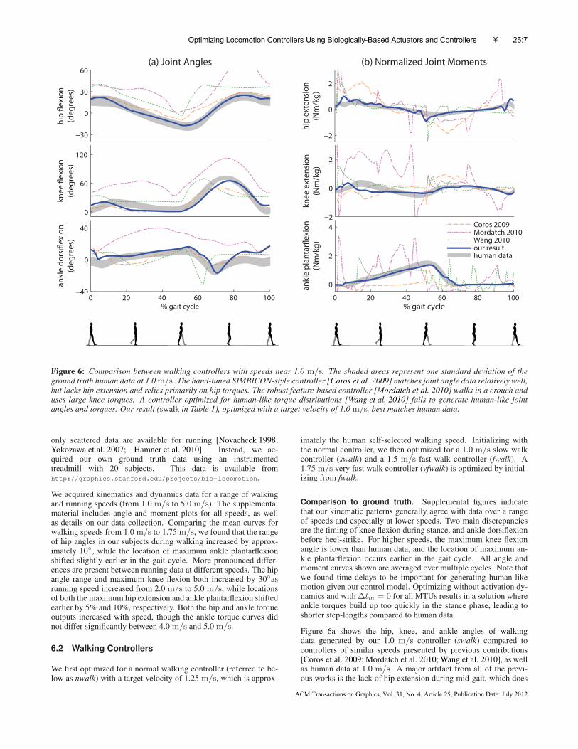
Figure 7: Comparison of running. Our result is optimized with a target velocity of 4.0 m/s. The shaded regions represent one standarddeviation of the human running data at 4.0m/s.
6.3 Running Controllers
Our controller architecture and objective function is not limited orspecific to walking alone. By simply changing the target veloc-ity and initialization (changing the initial velocity from 1.3 m/sto 3.05 m/s, doubling the initial force feedback gains for GASand SOL, and bending the elbow), the same procedure yields run-ning controllers, without any modifications to the control parame-terization. In contrast, previous optimization-based control synthe-sis methods required including torque ratios specific to walking aspart of the objective [Wang et al. 2009] or adding spring elementsfor running [Wu and Popovic 2010]. Our unified approach to bothwalking and running is consistent with the view that humans se-lect between walking and running by minimizing energy at differentspeeds [Srinivasan and Ruina 2006].
We compare running motions generated by our controller at4.0 m/s with human running data in Figure 7. Our running kine-matic results do not match human data as well as walking, thoughthe basic features of the curves are still present. A main discrep-ancy is that our hip and knee joints both reach maximum extensionearlier than human running data. Similar to our walking results, ourknee joint flexes less during the stance phase compared to humans.Our maximum knee flexion is also lower than human data.
Figure 7b reveals possible causes for the kinematic differences. Ourknee extension torque reaches maximum earlier than human data,which can cause the knee to extend too quickly during the stancephase. On the other hand, our plantarflexion torques have a lowerpeak than human data, resulting in a strategy that relies on the knees
more than the ankles. In the supplemental material and the video,we include results for running at speeds ranging from 3.0 m/s to5.0 m/s. The faster running results are optimized sequentially in0.5 m/s increments (e.g., 4.0 m/s initialized from 3.5 m/s). Asthe target velocity increases, finding a satisfactory local minimumappears more difficult. We use 100 samples per iteration and a0.25 m/s optimization increment for speeds over 4.0m/s.
6.4 Robustness
In this work, we have chosen to focus on reproducing human-like kinematics and torque trajectories. Likely due to our mod-eling of human-like torque generation and activation delays, ourcontrollers cannot tolerate nearly as much external force as re-cently developed controllers for purely joint-actuated characters[Mordatch et al. 2010; Wang et al. 2010]. However, we can stillfollow Wang et al. [2010] and optimize explicitly for controllersthat can deal with external forces. In particular, we optimized con-trollers that can tolerate 100 N, 0.4 s pushes to the torso. Thesecontrollers chose to walk in a stiff crouch gait, with lowered COMand a constantly dorsiflexed ankle to ensure foot clearance (see ac-companying video). Note that 100N is approximately the weight ofa 10 kg object, a significant push to a human. Comparatively, thecorresponding 100 N controller presented by Wang et al. [2010],who did not model biological torque generation constraints, did notemploy a gait that is significantly different from the undisturbedbaseline controller. We also optimized for a 4.0 m/s running con-troller tolerant of 50 N, 0.4 s pushes, as shown in the video.
Optimizing Locomotion Controllers Using Biologically-Based Actuators and Controllers • 25:9
ACM Transactions on Graphics, Vol. 31, No. 4, Article 25, Publication Date: July 2012

7 Discussion
We have presented a biologically-motivated control parameteriza-tion that can be used to automatically generate 3D human-like walk-ing and running controllers of different speeds. Controllers are op-timized to satisfy a set of high-level task terms while minimizingan effort term based on modeling the rate of metabolic energy ex-penditure. Notably, walking and running emerge from the sameoptimization process simply by changing the target velocity andinitialization. Through comparisons to kinematic and torque dataof human walking, we show that our results adopt a human-liketorque generation strategy while producing kinematic data signif-icantly closer to humans than previous work. Our work demon-strates the importance of modeling constraints on torque generationdue to muscle physiology, both in restricting the space of possibletorque trajectories and in providing a realistic model of effort.
We chose to focus on generating human-like locomotion in astraight line and on flat ground. A natural extension is to investigatewhether our control parameterization and effort term can be com-bined with the popular task-space controllers [Coros et al. 2010;de Lasa et al. 2010; Wu and Popovic 2010] and higher-level plan-ning [Coros et al. 2009; Mordatch et al. 2010] to create human-like motions on uneven terrains [Wu and Popovic 2010] or obstaclecourses [Mordatch et al. 2010; Ye and Liu 2010]—scenarios thathave only been addressed using purely joint-actuated characters.
Finally, an exciting area for future work is to automatically synthe-size locomotion controllers for more detailed, fully muscle-actuatedhuman models [Weinstein et al. 2008; Lee et al. 2009]. As we havetouched on in Section 6.2, our approach can be used to develop pre-dictive biomechanical models to investigate the effects of muscleand control properties on gait. However, more scientific valida-tion of our simulation results is needed before we can concludethat our results apply to real humans. One clear aspect for im-provement is to adopt a more physically-accurate simulation en-gine [Sherman et al. 2011], as ODE “emphasizes speed and stabil-ity over physical accuracy” [Smith 2006]. More accurate simula-tions and detailed models present additional computational chal-lenges both in simulation speed and in parameter optimization, butare crucial for potential scientific and medical applications.
Acknowledgements
We thank Stelian Coros and Igor Mordatch for making their sim-ulation data available. Thanks to Jared Duke for early contribu-tions, Tim Dorn for comments on the manuscript, and Ajay Seth,Edith Arnold, and Katherine Steele for inspiring technical discus-sions. We thank the anonymous reviewers for their helpful and con-structive comments. This work was funded in part by NSF grantsIIS-1017938 and CNS-0619926, NIH grants U54 GM072970, R24HD065690, and R01 HD033929, and an AWS research grant. Thisresearch was conducted in conjunction with the Intel Science andTechnology Center for Visual Computing.
References
ACKERMANN, M., AND VAN DEN BOGERT, A. J. 2010. Optimal-ity principles for model-based prediction of human gait. Journalof Biomechanics 43, 6, 1055–1060.
ALEXANDER, R. M. 2003. Principles of Animal Locomotion.Princeton University Press.
ANDERSON, F. C., AND PANDY, M. G. 2001. Dynamic optimiza-tion of human walking. Journal of Biomechanical Engineering123, 5, 381–390.
ANDERSON, F. C. 1999. A dynamic optimization solution for acomplete cycle of normal gait. PhD thesis, University of Texasat Austin.
BHARGAVA, L. J., PANDY, M. G., AND ANDERSON, F. C. 2004.A phenomenological model for estimating metabolic energyconsumption in muscle contraction. Journal of Biomechanics37, 81–88.
BLICKHAN, R. 1989. The spring-mass model for running andhopping. Journal of Biomechanics 22, 1217–1227.
COLLINS, S., RUINA, A., TEDRAKE, R., AND WISSE, M. 2005.Efficient bipedal robots based on passive-dynamic walkers. Sci-ence 307, 5712, 1082–1085.
COROS, S., BEAUDOIN, P., AND VAN DE PANNE, M. 2009.Robust task-based control policies for physics-based characters.ACM Transactions on Graphics 28, 5.
COROS, S., BEAUDOIN, P., AND VAN DE PANNE, M. 2010. Gen-eralized biped walking control. ACM Transactions on Graphics29, 4.
DA SILVA, M., ABE, Y., AND POPOVIC, J. 2008. Interactivesimulation of stylized human locomotion. ACM Transactions onGraphics 27, 3.
DE LASA, M., MORDATCH, I., AND HERTZMANN, A. 2010.Feature-based locomotion controllers. ACM Transactions onGraphics 29, 4.
FALOUTSOS, P., VAN DE PANNE, M., AND TERZOPOULOS, D.2001. Composable controllers for physics-based character ani-mation. In Proc. SIGGRAPH, ACM.
FULL, R. J., AND KODITSCHEK, D. E. 1999. Templates andanchors: Neuromechanical hypotheses of legged locomotion onland. The Journal of Experimental Biology 202, 23, 3325–3332.
GEYER, H., AND HERR, H. 2010. A muscle-reflex model that en-codes principles of legged mechanics produces human walkingdynamics and muscle activities. IEEE Transactions on NeuralSystems and Rehabilitation Engineering 18, 3, 263–273.
GEYER, H., SEYFARTH, A., AND BLICKHAN, R. 2003. Positiveforce feedback in bouncing gaits? Proceedings of the RoyalSociety B 270, 2173–2183.
HAMNER, S. R., SETH, A., AND DELP, S. L. 2010. Musclecontributions to propulsion and support during running. Journalof Biomechanics 43, 2709–2716.
HANSEN, N. 2006. The CMA evolution strategy: A comparingreview. In Towards a New Evolutionary Computation. Springer,75–102.
HASE, K., MIYASHITA, K., OK, S., AND ARAKAWA, Y. 2003.Human gait simulation with a neuromusculoskeletal model andevolutionary computation. Journal of Visualization and Com-puter Animation 14, 2, 73–92.
HODGINS, J. K., WOOTEN, W. L., BROGAN, D. C., AND
O’BRIEN, J. F. 1995. Animating human athletics. In Proc.SIGGRAPH, ACM.
JAIN, S., AND LIU, C. K. 2011. Controlling physics-based char-acters using soft contacts. ACM Transactions on Graphics 30,6.
JAIN, S., YE, Y., AND LIU, C. K. 2009. Optimization-basedinteractive motion synthesis. ACM Transactions on Graphics28, 1.
25:10 • J. Wang et al.
ACM Transactions on Graphics, Vol. 31, No. 4, Article 25, Publication Date: July 2012
KAY, R. M., RETHIEFSEN, S. A., SKAGGS, D., AND LEET, A.2002. Outcome of medial versus combined medial and lateralhamstring lengthening surgery in cerebral palsy. Journal of Pe-diatric Orthopaedics 22, 2, 169–172.
KUO, A. D. 2001. A simple model of bipedal walking predicts thepreferred speed-step length relationship. Journal of Biomechan-ical Engineering 123, 3, 264–269.
KWON, T., AND HODGINS, J. 2010. Control systems for hu-man running using an inverted pendulum model and a referencemotion capture sequence. In Proc. Symposium on Computer An-imation, ACM SIGGRAPH/Eurographics.
LASZLO, J. F., VAN DE PANNE, M., AND FIUME, E. 1996. Limitcycle control and its application to the animation of balancingand walking. In Proc. SIGGRAPH, ACM.
LEE, S.-H., AND TERZOPOULOS, D. 2006. Heads up!: Biome-chanical modeling and neuromuscular control of the neck. ACMTransactions on Graphics 25, 3.
LEE, Y., TERZOPOULOS, D., AND WATERS, K. 1995. Realisticmodeling for facial animation. In Proc. SIGGRAPH, ACM.
LEE, S.-H., SIFAKIS, E., AND TERZOPOULOS, D. 2009. Com-prehensive biomechanical modeling and simulation of the upperbody. ACM Transactions on Graphics 28, 4.
LEE, Y., KIM, S., AND LEE, J. 2010. Data-driven biped control.ACM Transactions on Graphics 29, 4.
LIU, C. K., HERTZMANN, A., AND POPOVIC, Z. 2005. Learningphysics-based motion style with nonlinear inverse optimization.ACM Transactions on Graphics 24, 3.
LIU, M. Q., ANDERSON, F. C., SCHWARTZ, M. H., AND DELP,S. L. 2008. Muscle contributions to support and progressionover a range of walking speeds. Journal of Biomechanics 41,3243–3252.
MORDATCH, I., DE LASA, M., AND HERTZMANN, A. 2010. Ro-bust physics-based locomotion using low-dimensional planning.ACM Transactions on Graphics 29, 3.
MUICO, U., LEE, Y., POPOVIC, J., AND POPOVIC, Z. 2009.Contact-aware nonlinear control of dynamic characters. ACMTransactions on Graphics 28, 3.
MURAI, A., AND YAMANE, K. 2011. A neuromuscular locomo-tion controller that realizes human-like responses to unexpecteddisturbances. In Proc. International Conference on Robotics andAutomation, IEEE, 1997–2002.
NOVACHECK, T. F. 1998. The biomechanics of running. Gait andPosture 7, 1, 77–95.
PERRY, J., AND BURNFIELD, J. 2010. Gait Analysis: Normal andPathological Function. Slack Incorporated.
RAIBERT, M. H., AND HODGINS, J. K. 1991. Animation of dy-namic legged locomotion. In Proc. SIGGRAPH, ACM.
SCHULTZ, G., AND MOMBAUR, K. 2010. Modeling and opti-mal control of human-like running. IEEE/ASME Transactionson Mechatronics 15, 5, 783–791.
SHERMAN, M., SETH, A., AND DELP, S. L. 2011. Simbody:Multibody dynamics for biomedical research. In Proc. Sympo-sium on Human Body Dynamics, Vol. 2, IUTAM, 241–261.
SIFAKIS, E., NEVEROV, I., AND FEDKIW, R. 2005. Automaticdetermination of facial muscle activations from sparse motioncapture marker data. ACM Transactions on Graphics 24, 3.
SMITH, R., 2006. Open Dynamics Engine v0.5 User Guide.http://www.ode.org/ode-latest-userguide.html, Feb.
SRINIVASAN, M., AND RUINA, A. 2006. Computer optimizationof a minimal biped model discovers walking and running. Nature439, 72–75.
STEELE, K. M., SETH, A., HICKS, J. L., SCHWARTZ, M. S.,AND DELP, S. L. 2010. Muscle contributions to support andprogression during single-limb stance in crouch gait. Journal ofBiomechanics 43, 2099–2105.
SUEDA, S., KAUFMAN, A., AND PAI, D. K. 2008. Musculotendonsimulation for hand animation. ACM Transactions on Graphics27, 3.
TAGA, G. 1995. A model of the neuro-musculo-skeletal systemfor human locomotion. I. Emergence of basic gait. BiologicalCybernetics 73, 2, 97–111.
TIMONEY, J. M., INMAN, W. S., QUESADA, P. M., SHARKEY,P. F., BARRACK, R. L., SKINNER, H. B., AND ALEXANDER,A. H. 1993. Return of normal gait patterns after anterior cru-ciate ligament reconstruction. The American Journal of SportsMedicine 21, 6, 887–889.
WANG, J. M., FLEET, D. J., AND HERTZMANN, A. 2009. Opti-mizing walking controllers. ACM Transactions on Graphics 28,5.
WANG, J. M., FLEET, D. J., AND HERTZMANN, A. 2010. Op-timizing walking controllers for uncertain inputs and environ-ments. ACM Transactions on Graphics 29, 4.
WATERS, K. 1987. A muscle model for animation three-dimensional facial expression. In Proc. SIGGRAPH, ACM.
WEINSTEIN, R., GUENDELMAN, E., AND FEDKIW, R. 2008.Impulse-based control of joints and muscles. IEEE Transactionson Visualization and Computer Graphics 14, 1, 37–46.
WU, J.-C., AND POPOVIC, Z. 2010. Terrain-adaptive bipedal lo-comotion control. ACM Transactions on Graphics 29, 4.
YE, Y., AND LIU, C. K. 2010. Optimal feedback control forcharacter animation using an abstract model. ACM Transactionson Graphics 29, 4.
YIN, K., LOKEN, K., AND VAN DE PANNE, M. 2007. SIMBI-CON: Simple biped locomotion control. ACM Transactions onGraphics 26, 3.
YOKOZAWA, T., FUJII, N., AND AE, M. 2007. Muscle activitiesof the lower limb during level and uphill running. Journal ofBiomechanics 40, 15, 3467–3475.
ZAJAC, F. E. 1989. Muscle and tendon: Properties, models, scal-ing, and application to biomechanics and motor control. CriticalReviews in Biomedical Engineering 17, 4, 359–411.
ZORDAN, V. B., CELLY, B., CHIU, B., AND DILORENZO, P. C.2006. Breathe easy: Model and control of human respiration forcomputer animation. Graphical Models 68, 2, 113–132.
Optimizing Locomotion Controllers Using Biologically-Based Actuators and Controllers • 25:11
ACM Transactions on Graphics, Vol. 31, No. 4, Article 25, Publication Date: July 2012


![arXiv:1709.00643v1 [cs.CV] 2 Sep 2017 · Fast Image Processing with Fully-Convolutional Networks Qifeng Chen Jia Xu Vladlen Koltun Intel Labs Input Our result L 0 smoothing Multiscale](https://static.fdocuments.in/doc/165x107/5e9f34d1624c2439b8313d20/arxiv170900643v1-cscv-2-sep-2017-fast-image-processing-with-fully-convolutional.jpg)


![IN THE SUPREME COURT OF ZAMBIA - Koltun Attorney · 1. Wandsworth LBC v Michalok [2002] 4 ALLER 144 2. Shilling Bob Zinka v Attorney-General (1990-1992) ZR 73. 3. Mifiboshe Walulya](https://static.fdocuments.in/doc/165x107/6074fa067ba06f6e937c202d/in-the-supreme-court-of-zambia-koltun-attorney-1-wandsworth-lbc-v-michalok-2002.jpg)