Optimized Synthesis Conditions of Polyethersulfone Support … · Different types of...
16
Copyright © 2014 Korean Society of Environmental Engineers http://eeer.org Research Paper http://dx.doi.org/10.4491/eer.2014.045 pISSN 1226-1025 eISSN 2005-968X In Press, Uncorrected Proof Environ. Eng. Res. 2014 Optimized Synthesis Conditions of Polyethersulfone Support Layer for Enhanced Water Flux for Thin Film Composite Membrane Moon Son 1 , Hyeongyu Choi 1 , Hosik Park 2 , Heechul Choi 1† 1 School of Environmental Science and Engineering, Gwangju Institute of Science and Technology, 123 Cheomdangwagi-ro, Buk-gu, Gwangju 500-712, Korea 2 Research Center for Environmental Resources and Processes, Korea Research Institute of Chemical Technology, Daejeon 305-600, Korea Abstract Different types of polyethersulfone (PES) support layer for a thin film composite membrane were synthesized under various synthesis conditions using the phase inversion method to study the combined effects of substrate, adhesive, and pore former. The permeability, selectivity, pore structure, and morphology of the prepared membranes were analyzed to evaluate the membrane performance. The combined use of substrate, adhesive, and pore former produced a thinner dense top layer, with more straight finger-like pores. The pure water permeation (PWP) of the optimized PES membrane was 27.42 L/m2h (LMH), whereas that of bare PES membrane was 3.24 LMH. Moreover, membrane selectivity, represented as divalent ion (CaSO4) rejection, was not sacrificed under the synthesis conditions, which produced the dramatically enhanced PWP. The high permeability and selectivity of the PES membrane produced under the optimized synthesis conditions suggest that it can be utilized as a support layer for TFC membranes. Keywords: Membrane, Optimization, Polyethersulfone, Support Layer, Synthesis Conditions Received July 16, 2014 Accepted November 3, 2014 † Corresponding Author E-mail: [email protected] Tel: +82-62-715-2441 Fax: +82-62-715-2434 This is an Open Access article distributed under the terms of the Creative Commons Attribution Non-Commercial Li- cense (http://creativecommons.org/licenses/by-nc/3.0/) which permits unrestricted non-commercial use, distribution, and repro- duction in any medium, provided the original work is properly cited.
Transcript of Optimized Synthesis Conditions of Polyethersulfone Support … · Different types of...

Copyright © 2014 Korean Society of Environmental Engineers http://eeer.org
Research Paperhttp://dx.doi.org/10.4491/eer.2014.045 pISSN 1226-1025 eISSN 2005-968X In Press, Uncorrected Proof
Environ. Eng. Res. 2014
Optimized Synthesis Conditions of Polyethersulfone Support Layer for Enhanced Water Flux for Thin Film Composite Membrane
Moon Son1, Hyeongyu Choi1, Hosik Park2, Heechul Choi1†
1School of Environmental Science and Engineering, Gwangju Institute of Science and Technology, 123 Cheomdangwagi-ro, Buk-gu, Gwangju 500-712, Korea2Research Center for Environmental Resources and Processes, Korea Research Institute of Chemical Technology, Daejeon 305-600, Korea
AbstractDifferent types of polyethersulfone (PES) support layer for a thin film composite membrane were synthesized under various synthesis conditions using the phase inversion method to study the combined effects of substrate, adhesive, and pore former. The permeability, selectivity, pore structure, and morphology of the prepared membranes were analyzed to evaluate the membrane performance. The combined use of substrate, adhesive, and pore former produced a thinner dense top layer, with more straight finger-like pores. The pure water permeation (PWP) of the optimized PES membrane was 27.42 L/m2h (LMH), whereas that of bare PES membrane was 3.24 LMH. Moreover, membrane selectivity, represented as divalent ion (CaSO4) rejection, was not sacrificed under the synthesis conditions, which produced the dramatically enhanced PWP. The high permeability and selectivity of the PES membrane produced under the optimized synthesis conditions suggest that it can be utilized as a support layer for TFC membranes.
Keywords: Membrane, Optimization, Polyethersulfone, Support Layer, Synthesis Conditions
Received July 16, 2014 Accepted November 3, 2014† Corresponding AuthorE-mail: [email protected]: +82-62-715-2441 Fax: +82-62-715-2434
This is an Open Access article distributed under the terms of the Creative Commons Attribution Non-Commercial Li-cense (http://creativecommons.org/licenses/by-nc/3.0/)
which permits unrestricted non-commercial use, distribution, and repro-duction in any medium, provided the original work is properly cited.

1. Introduction 1
Recently, 80% of the world’s population live in regions where water security poses a threat [1]. 2
Population growth, industrialization, contamination of available freshwater resources, and climate 3
change are all accelerating water scarcity [2]. To address the problem, Seawater desalination has 4
been received great attention due to the plentiful supply of seawater [3-5]. Additional advantages of 5
desalination are the compact of process, water quality, and low operating cost. Current approaches 6
to desalination include membrane-based technology, distillation, freezing, and the ion exchange 7
method [6-8]. In membrane-based seawater desalination, thin film composite (TFC) membranes are 8
widely used due to their reduced internal concentration polarization, which results in high water 9
flux, and their high mechanical strength [9]. 10
Generally, TFC membranes are composed of an active layer, support layer, and substrate [10-12]. 11
Polyamide membranes, produced by interfacial polymerization, are widely used as the active layer 12
due to their high water flux and salt rejection, both highly desirable properties of membranes for 13
seawater desalination [9]. To deposit polyamide layer on the membrane surface, a high acid 14
resistance polymer is required as the support layer. Polysulfone (PSU) is considered as good 15
candidate as a support layer due to its high acid resistance, mechanical strength, and water flux [13]. 16
However, it has been recently reported that polyethersulfone (PES) produces more finger-like pores 17
than PSU due to the former’s higher polarity and hydrophilicity, thereby enhancing water flux. In 18
addition, PES membranes have a higher mechanical strength than PSU ones due to the high 19
flexibility of the polymer, something that is needed in a water treatment membrane [14]. Therefore, 20
PES is considered a strong candidate as a support layer of TFC membranes. Moreover, the substrate 21
layer is essential component for the TFC membrane to resist high pressure in the desalination 22
process. A nonwoven fabric matrix is widely used as a substrate in this process due to the fabric’s 23
extremely high mechanical strength. 24
To date, in-depth research on PES support layer synthetic conditions with or without nonwoven 25
1

fabric substrate for TFC membrane has not been revealed. During the support layer casting step for 26
TFC membrane, the polymer solution can readily penetrate the substrate because of its large pore 27
size. The adhesive solvent, which is used to make a strong bond between the support layer and the 28
substrate, can accelerate penetration phenomena. Bottom macro void of support layer can penetrate 29
into the substrate and thickness of support layer can be reduced due to the effects of substrate and 30
adhesive solvent. Thus, maximizing the performance of TFC membranes for seawater desalination 31
requires optimizing the synthesis conditions of components of the support layer, such as the 32
presence of substrate or adhesive. 33
As a pore former, the effects of polyvinylpyrrolidone (PVP) on the performance of PES membranes 34
with regard to water flux or rejection have been studied [15]. It produces a thin top dense layer 35
during the phase inversion step and increases membrane hydrophilicity due to its inherent 36
hydrophilicity [16-20]. However, the combined effects of substrate, adhesive, and pore former on 37
PES in TFC membranes have not been studied so far. 38
Therefore, we synthesized different types of PES membrane via the phase inversion method under 39
different synthesis conditions (i.e., with and/or without the presence of substrate, adhesive, and pore 40
former). In addition, we determined the permeability, selectivity, and morphology of the resulting 41
PES membrane, which can be utilized as a support layer for TFC membranes in a further. 42
43
2. Materials and Methods 44
2.1. Materials 45
Deionized (DI) water was prepared using a water purification system (Synergy, Millipore, USA) 46
with resistivity of 18.2 mΩ-cm at 25° C. An ultrasonicator (B8510-MT, Branson, USA) was used to 47
remove invisible air bubbles in the polymer solutions. 48
PES (Solvay Korea Co, H-2000) with a molecular weight (Mw) of 62,000–64,000 g/mol was used 49
for PES membrane synthesis. The solvent was n-methyl-2-pyrrolidinone (NMP) (anhydrous 99.5%, 50
2
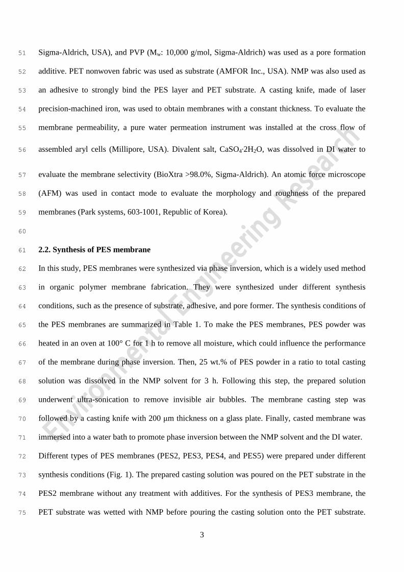
Sigma-Aldrich, USA), and PVP (Mw: 10,000 g/mol, Sigma-Aldrich) was used as a pore formation 51
additive. PET nonwoven fabric was used as substrate (AMFOR Inc., USA). NMP was also used as 52
an adhesive to strongly bind the PES layer and PET substrate. A casting knife, made of laser 53
precision-machined iron, was used to obtain membranes with a constant thickness. To evaluate the 54
membrane permeability, a pure water permeation instrument was installed at the cross flow of 55
assembled aryl cells (Millipore, USA). Divalent salt, CaSO4·2H2O, was dissolved in DI water to 56
evaluate the membrane selectivity (BioXtra >98.0%, Sigma-Aldrich). An atomic force microscope 57
(AFM) was used in contact mode to evaluate the morphology and roughness of the prepared 58
membranes (Park systems, 603-1001, Republic of Korea). 59
60
2.2. Synthesis of PES membrane 61
In this study, PES membranes were synthesized via phase inversion, which is a widely used method 62
in organic polymer membrane fabrication. They were synthesized under different synthesis 63
conditions, such as the presence of substrate, adhesive, and pore former. The synthesis conditions of 64
the PES membranes are summarized in Table 1. To make the PES membranes, PES powder was 65
heated in an oven at 100° C for 1 h to remove all moisture, which could influence the performance 66
of the membrane during phase inversion. Then, 25 wt.% of PES powder in a ratio to total casting 67
solution was dissolved in the NMP solvent for 3 h. Following this step, the prepared solution 68
underwent ultra-sonication to remove invisible air bubbles. The membrane casting step was 69
followed by a casting knife with 200 μm thickness on a glass plate. Finally, casted membrane was 70
immersed into a water bath to promote phase inversion between the NMP solvent and the DI water. 71
Different types of PES membranes (PES2, PES3, PES4, and PES5) were prepared under different 72
synthesis conditions (Fig. 1). The prepared casting solution was poured on the PET substrate in the 73
PES2 membrane without any treatment with additives. For the synthesis of PES3 membrane, the 74
PET substrate was wetted with NMP before pouring the casting solution onto the PET substrate. 75
3

NMP was used as an adhesive between the casting solution and the PET substrate. In PES4, 1 wt.% 76
of PVP as a pore former was added into the casting solution. Both adhesive and pore former were 77
applied for the synthesis of PES5 membrane. All the synthesized membranes were stored in DI 78
water for one day to remove solvent remaining inside the membrane prior to further experiments. 79
80
Table 1. Synthesis Conditions of PES Membranes 81
Membrane classification PES PES2 PES3 PES4 PES5
Substrate (PETa)) X O O O O
Adhesive (NMPb)) X X O X O
Pore former (PVPc)) X X X O O
a) PET: polyethylene terephthalate. 82
b) NMP: n-methyl-2-pyrrolidinone. 83
c) PVP: polyvinylpyrrolidone. 84
85
86
4

Fig. 1. Schematic of synthesis conditions of PES membranes with or without substrate (PET), 87
adhesive (NMP) and pore former (PVP). PES2 membrane has substrate only. PES3 membrane 88
has both substrate and adhesive. PES4 membrane has both substrate and pore former. PES5 89
membrane has substrate, adhesive, and pore former. 90
91
2.3. Lab-scale UF filtration 92
Lab-scale UF filtration was carried out cross-flow to measure the water flux of the PES membranes. 93
The effective membrane area of each cross-flow cell was 18.56 cm2, the temperature was kept at 20 ° 94
C, and the circulation flow was maintained at 400 ccm. All the membranes were stabilized at a 95
trans-membrane pressure (TMP) of 4.14 bar (60 psi) for 4 h, and then the TMP was kept at 4.14 bar 96
for 3 h to examine the water flux. The schematic of the lab-scale cross flow UF set-up is illustrated 97
in Fig. 2. To evaluate the membrane selectivity with regard to rejection of divalent ions, the 98
following equation was employed: 99
100
R (%) = (1 − 𝐶𝐶𝑝𝑝𝐶𝐶𝑓𝑓
) × 100 , (1) 101
102
where R is the CaSO4 rejection, and Cf and Cp are the concentrations of the feed water and permeate, 103
respectively. The CaSO4 rejection rate was calculated by measuring the conductivity and converting 104
the values using a correlation curve between the conductivity and concentration of CaSO4 (Fig. 3.). 105
Fig. 3 shows that CaSO4 was fully dissolved in DI water with concentration less than 200 ppm. 106
107
5

108
Fig. 2. Schematic of lab-scale cross-flow UF instrument. 109
110
Fig. 3. Correlation curve between conductivity (μS) and CaSO4 concentration (ppm). 111
112
2.4. Analysis of Membrane Structure and Surface Morphology 113
The membrane thickness and pore structure were measured by scanning electron microscope (SEM). 114
The membrane was fully dried at 40 °C for one day in an oven and immersed in liquid nitrogen. The 115
frozen membrane was then broken, and its cross-section was measured with SEM. The surface 116
morphology and roughness of the prepared membranes were measured with an AFM. The analyzed 117
6
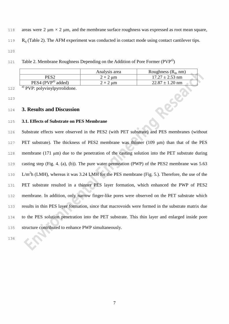
areas were 2 μm × 2 μm, and the membrane surface roughness was expressed as root mean square, 118
Rq (Table 2). The AFM experiment was conducted in contact mode using contact cantilever tips. 119
120
Table 2. Membrane Roughness Depending on the Addition of Pore Former (PVPa)) 121
Analysis area Roughness (Rq, nm) PES2 2 × 2 μm 17.27 ± 2.53 nm
PES4 (PVPa) added) 2 × 2 μm 22.87 ± 1.20 nm a) PVP: polyvinylpyrrolidone. 122
123
3. Results and Discussion 124
3.1. Effects of Substrate on PES Membrane 125
Substrate effects were observed in the PES2 (with PET substrate) and PES membranes (without 126
PET substrate). The thickness of PES2 membrane was thinner (109 μm) than that of the PES 127
membrane (171 μm) due to the penetration of the casting solution into the PET substrate during 128
casting step (Fig. 4. (a), (b)). The pure water permeation (PWP) of the PES2 membrane was 5.63 129
L/m2h (LMH), whereas it was 3.24 LMH for the PES membrane (Fig. 5.). Therefore, the use of the 130
PET substrate resulted in a thinner PES layer formation, which enhanced the PWP of PES2 131
membrane. In addition, only narrow finger-like pores were observed on the PET substrate which 132
results in thin PES layer formation, since that macrovoids were formed in the substrate matrix due 133
to the PES solution penetration into the PET substrate. This thin layer and enlarged inside pore 134
structure contributed to enhance PWP simultaneously. 135
136
7

137
Fig. 4. SEM images of synthesized PES membrane (a) PES, (b) PES2, (c) PES3, (d) PES4, and 138
(e) PES5. 139
8

140
Fig. 5. Pure water permeation (PWP) of synthesized membranes following a UF filtration test 141
for 3 hr. 142
143
3.2. Effects of Adhesive on PES Membrane 144
Adhesive was used in the PES3 but not the PES2 membrane. The PES3 membrane was significantly 145
thinner (46 μm) than the PES2 membrane (109 μm) due to accelerated penetration of the casting 146
solution into the PET substrate during casting step caused by pretreatment of PET substrate with 147
adhesive (Fig. 4. (b), (c)). The casting solution readily penetrated the adhesive-wetted PET substrate. 148
The PWP of the PES3 membrane was 7.55 LMH PWP, whereas that of the PES2 membrane was 149
5.63 LMH. The thinner membrane of the PES3 membrane with the adhesive enhanced the PWP 150
(Fig. 5.). 151
152
3.3. Effects of pore former on PES membrane 153
The effects of the pore former, PVP, on the PES membrane were determined by observing the 154
9
difference in the performance of the PES2 and PES4 membranes. Previous research reported that 155
pore former, such as PVP, produces a thin top dense layer, straight finger-like pores, and a thick 156
membrane due to increased hydrophilicity and casting solution viscosity [16-20]. In this experiment, 157
1 wt.% PVP was used because a previously reported study showed that 1 wt.% of PVP can decrease 158
the thickness of the top dense layer without significantly changing the size of the surface pores [21]. 159
The PES4 membrane, in which pore former was used in the casting solution, had more straight 160
finger-like pores than the PES2 membrane (Fig. 4. (b), (d)). In addition, the thickness of the 161
membrane increased from 109 μm to 122 μm due to the increased viscosity of the casting solution 162
after adding the pore forming agent. Although the addition of the pore former only slightly 163
increased the thickness of the PES4 membrane, the PWP of the PES4 membrane was 11.10 LMH, 164
whereas that of the PES2 membrane was 5.63 LMH (Fig. 5). It can be explained that more straight 165
finger like pore formation caused by addition of pore former increased PWP. 166
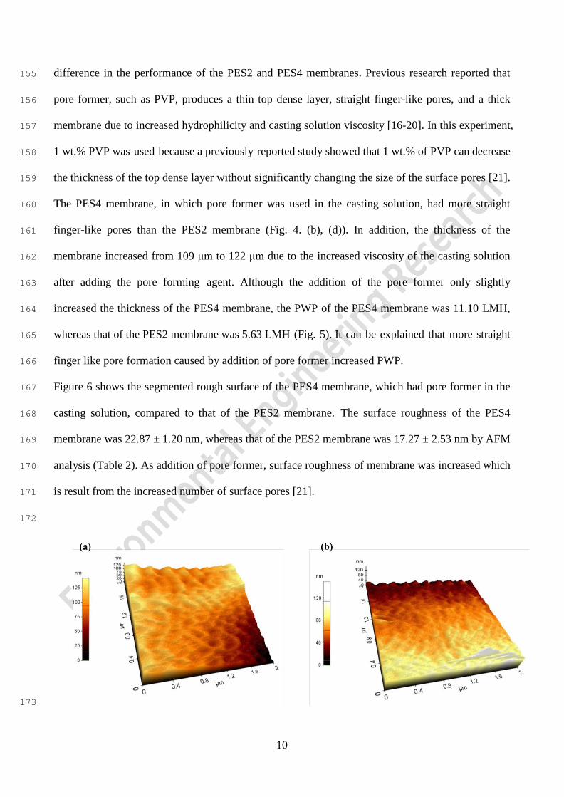
Figure 6 shows the segmented rough surface of the PES4 membrane, which had pore former in the 167
casting solution, compared to that of the PES2 membrane. The surface roughness of the PES4 168
membrane was 22.87 ± 1.20 nm, whereas that of the PES2 membrane was 17.27 ± 2.53 nm by AFM 169
analysis (Table 2). As addition of pore former, surface roughness of membrane was increased which 170
is result from the increased number of surface pores [21]. 171
172
173
10

Fig. 6. AFM images of (a) PES2, (b) PES4 membrane roughness depending on the addition of 174
pore former (PVP). PES2 membrane (without pore former); PES4 membrane (with pore 175
former). 176
177
3.4. Combined Effects on PES Membrane 178
The PES5 membrane was formulated with adhesive, pore former, and substrate. PES5 membrane 179
had the highest PWP (27.42 LMH), among all the prepared membranes (Fig. 5.). The PWP of the 180
membranes as well as membrane selectivity were measured using 0.001 M (200 ppm) CaSO4 181
solution as feed water (Fig. 7). Although the PWP membranes containing the pore former was 182
enhanced due to the increased numbers of straight finger-like pores, the addition of the pore former 183
less decrease CaSO4 rejection. Comparison of the PWP and CaSO4 rejection of the PES4 and PES5 184
membranes showed that the use of adhesive did not influence the properties of active pores. 185
Therefore, the synthesis conditions of the PES5 membrane resulted in dramatically enhanced PWP 186
without sacrificing membrane selectivity, suggesting that these conditions can be used to produce a 187
suitable support layer for TFC membranes. 188
189
11

190
Fig. 7. Divalent ion (CaSO4) rejection and pure water permeation (PWP) of synthesized 191
membranes. 192
193
4. Conclusions 194
This study revealed the effects of synthetic conditions on the PWP, divalent salt rejection, pore 195
structure, and morphology of PES membranes. The PWP of the membrane with only PES polymer 196
was 3.24 LMH. After applying the PET substrate, the PWP of the membrane changed to 5.63 LMH. 197
Using both PET substrate and NMP adhesive produced a thinner membrane due to penetration of 198
the casting solution into the substrate, which enhanced the PWP to 7.55 LMH. Although the 199
addition of PVP pore former slightly thickened the membrane due to the increased viscosity of the 200
casting solution, the PWP was improved to 11.10 LMH due to straight finger-like pore formation 201
and increased number of surface pores. With PET substrate, NMP adhesive, and PVP pore former, 202
12
the PWP of the optimized PES membrane reached to 27.42 LMH. In addition, divalent ion rejection 203
(CaSO4) was maintained around 80%, regardless of the synthetic conditions applied in this study. 204
Therefore, the high permeability of the PES support without sacrificing selectivity was fabricated 205
under the optimized synthesis conditions, which can be utilized as a potential support for TFC 206
membranes 207
208
Acknowledgment 209
This research was supported by the R&D Program for Society of the National Research Foundation 210
(NRF) funded by the Ministry of Science, ICT & Future Planning (Grant number : NRF-211
2014M3C8A4030498 and 2012R1A2A2A03046711). In addition, this work was funded as a Basic 212
Research Project through a grant provided by the Gwangju Institute of Science and Technology. 213
214
215
13

References 216
217 1. Balancing water supply and wildlife. Nature online. 2010. 218 219 2. M. Elimelech, W.A. Phillip. The Future of Seawater Desalination: Energy, Technology, and the 220
Environment. Science. 2011;333;712-717. 221 222 3. V.G. Gude, N. Nirmalakhandan, S. Deng. Renewable and sustainable approaches for 223
desalination, Renewable and Sustainable Energy Reviews. 2010;14;2641-2654. 224 225 4. M.A. Shannon, P.W. Bohn, M. Elimelech, J.G. Georgiadis, B.J. Marin˜as, A.M. Mayes. Science 226
and technology for water purification in the coming decades. Nature. 2008;452;301-310. 227 228 5. J. Lee, X. Ren, H.-W. Yu, S.-J. Kim, I.S. Kim. Membrane Biofouling of Seawater Reverse 229
Osmosis Initiated by Sporogenic Bacillus Strain. Environ. Eng. Res. 2010;15;141-147. 230 231 6. L.F. Greenlee, D.F. Lawler, B.D. Freeman, B. Marrot, P. Moulin. Reverse osmosis desalination: 232
Water sources, technology, and today's challenges. Water Res. 2009;43;2317-2348. 233 234 7. I.C. Karagiannis, P.G. Soldatos. Water desalination cost literature: review and assessment. 235
Desalination. 2008;223;448-456. 236 237 8. T. Matsuura. Progress in membrane science and technology for seawater desalination — a 238
review. Desalination. 2001;134;47-54. 239 240 9. K.P. Lee, T.C. Arnot, D. Mattia. A review of reverse osmosis membrane materials for 241
desalination—Development to date and future potential. J. Membr. Sci. 2011;370;1-22. 242 243 10. W.J. Lau, A.F. Ismail, N. Misdan, M.A. Kassim. A recent progress in thin film composite 244
membrane: A review. Desalination. 2012;287;190-199. 245 246 11. M.M. Pendergast, E.M.V. Hoek. A review of water treatment membrane nanotechnologies. 247
Energy & Environ. Sci. 2011;4;1946-1971. 248 249 12. D. Li, H. Wang. Recent developments in reverse osmosis desalination membranes, J. Mater. 250
Chem. 2010;20;4551-4566. 251 252 13. L.T. Rozelle, J.E. Cadotte, R.D. Corneliussen, E.E. Erickson. Final report on development of 253
new reverse osmosis membrane. 1968. 254 255 14. C. Barth, M.C. Goncalves, A.T.N. Pires, J. Roeder, B.A. Wolf. Asymmetric polysulfone and 256
polyethersulfone membranes: effects of thermodynamic conditions during formation on their 257 performance. J. Membr. Sci. 2000;169;287-299. 258
259 15. S.A. Al Malek, M.N. Abu Seman, D. Johnson, N. Hilal. Formation and characterization of 260
polyethersulfone membranes using different concentrations of polyvinylpyrrolidone. 261 Desalination. 2012;288;31-39. 262
263 16. M. Amirilargani, E. Saljoughi, T. Mohammadi, M.R. Moghbeli. Effects of coagulation bath 264
14

temperature and polyvinylpyrrolidone content on flat sheet asymmetric polyethersulfone 265 membranes. Polymer Eng. & Sci. 2010;50;885-893. 266
267 17. H. Susanto, M. Ulbricht, Characteristics. Performance and stability of polyethersulfone 268
ultrafiltration membranes prepared by phase separation method using different macromolecular 269 additives. J. Membr. Sci. 2009;327;125-135. 270
271 18. A. Rahimpour, S.S. Madaeni. Polyethersulfone (PES)/cellulose acetate phthalate (CAP) blend 272
ultrafiltration membranes: Preparation, morphology, performance and antifouling properties. J. 273 Membr. Sci. 2007;305;299-312. 274
275 19. J.-J. Qin, F.-S. Wong, Y. Li, Y.-T. Liu. A high flux ultrafiltration membrane spun from 276
PSU/PVP (K90)/DMF/1,2-propanediol. J. Membr. Sci. 2003;211;139-147. 277 278 20. J. Marchese, M. Ponce, N.A. Ochoa, P. Prádanos, L. Palacio, A. Hernández. Fouling behaviour 279
of polyethersulfone UF membranes made with different PVP. J. Membr. Sci. 2003;211;1-11. 280 281 21. A.F. Ismail, A.R. Hassan. Effect of additive contents on the performances and structural 282
properties of asymmetric polyethersulfone (PES) nanofiltration membranes. Sep. Purif. Technol. 283 2007;55;98-109. 284
285
286
287
15