Optimization of tram face with respect to passive safety · Optimization of tram face with respect...
10
Applied and Computational Mechanics 2 (2008) 53–62 Optimization of tram face with respect to passive safety L. Hynˇ c´ ık a,∗ , H. Kockov´ a a , L. ˇ C´ ıhalov´ a a , R. Cimrman a a New Technologies – Research Centre in the Westbohemian Region, University of WestBohemia in Pilsen, Univerzitn´ ı22, 306 14 Plzeˇ n, Czech Republic Received 22 August 2008; received in revised form 14 October 2008 Abstract An impact of a pedestrian and a tram or even an impact of two trams is a common traffic accident in towns. Hence there is an effort to develop such traffic means that minimize injuries of victims. The article deals with the optimization of placement of a previously proposed tram fender to decrease pedestrian injury risk. Further the influence of the tram fender made from different materials on passengers and tram driver injuries is investigated. The pedestrian, driver and passengers are modeled by a rigid body human model. The results analysis uses standard injury criteria based on body parts accelerations. c 2008 University of West Bohemia in Pilsen. All rights reserved. Keywords: biomechanical human model, passenger safety, tram driver safety, optimization of structures 1. Introduction Virtual modeling and numerical simulations are becoming the most frequent methods used to design and optimize safety traffic systems. Not only car traffic is responsible for a number of lives. In many towns trams are often used as popular transport means. In case of a tram versus pedestrian impact, the pedestrian generally faces the consequences. However, lots of traffic participants misvalue tram technical parameters. For example the braking distance may be influenced by weather conditions. According to the police traffic report in 1999, there were 1800 tram accidents in the Czech Republic, however, only 315 of them were caused by tram drivers, cf. [11]. Therefore the analysis of pedestrian impact seems to be an important application field of biomechanical simulations. The attention is also paid to tram driver and passengers safety. 2. Human body model Recently the biomechanical simulations come to be more and more significant. Biomechani- cal models of increasing complexity of a human body are developed and then applied in car industry, sport, virtual surgery, ergonomy and military. 2.1. ROBBY family The multi-body based model ROBBY2 has been developed since 1997 for industry applications, cf. [1]. Currently the ROBBY family contains the model of a 50 th percentile man and a 5 th percentile woman. The models structure is identical, differences can be found in the geometry, mass distribution and muscles and joints characteristics. Based on a simple scaling algorithm, cf. [3], the man and woman models in the age of 6 to 55 years can be created. The ROBBY2 ∗ Corresponding author. Tel.: +420 377 634 709, e-mail: [email protected]. 53
Transcript of Optimization of tram face with respect to passive safety · Optimization of tram face with respect...

Applied and Computational Mechanics 2 (2008) 53–62
Optimization of tram face with respect to passive safetyL. Hyncıka,∗, H. Kockovaa, L. Cıhalovaa, R. Cimrmana
aNew Technologies – Research Centre in the Westbohemian Region, University of West Bohemia in Pilsen, Univerzitnı22, 306 14 Plzen,Czech Republic
Received 22 August 2008; received in revised form 14 October 2008
Abstract
An impact of a pedestrian and a tram or even an impact of two trams is a common traffic accident in towns.Hence there is an effort to develop such traffic means that minimize injuries of victims. The article deals withthe optimization of placement of a previously proposed tram fender to decrease pedestrian injury risk. Further theinfluence of the tram fender made from different materials on passengers and tram driver injuries is investigated.The pedestrian, driver and passengers are modeled by a rigid body human model. The results analysis uses standardinjury criteria based on body parts accelerations.c© 2008 University of West Bohemia in Pilsen. All rights reserved.
Keywords: biomechanical human model, passenger safety, tram driver safety, optimization of structures
1. Introduction
Virtual modeling and numerical simulations are becoming the most frequent methods used todesign and optimize safety traffic systems. Not only car traffic is responsible for a number oflives. In many towns trams are often used as popular transport means. In case of a tram versuspedestrian impact, the pedestrian generally faces the consequences. However, lots of trafficparticipants misvalue tram technical parameters. For example the braking distance may beinfluenced by weather conditions. According to the police traffic report in 1999, there were 1800tram accidents in the Czech Republic, however, only 315 of them were caused by tram drivers,cf. [11]. Therefore the analysis of pedestrian impact seems to be an important application fieldof biomechanical simulations. The attention is also paid to tram driver and passengers safety.
2. Human body model
Recently the biomechanical simulations come to be more and more significant. Biomechani-cal models of increasing complexity of a human body are developed and then applied in carindustry, sport, virtual surgery, ergonomy and military.
2.1. ROBBY family
The multi-body based model ROBBY2 has been developed since 1997 for industry applications,cf. [1]. Currently the ROBBY family contains the model of a 50th percentile man and a 5th
percentile woman. The models structure is identical, differences can be found in the geometry,mass distribution and muscles and joints characteristics. Based on a simple scaling algorithm,cf. [3], the man and woman models in the age of 6 to 55 years can be created. The ROBBY2
∗Corresponding author. Tel.: +420 377 634 709, e-mail: [email protected].
53

L. Hyncık et al. / Applied and Computational Mechanics 2 (2008) 53–62
model has been successfully validated for a frontal impact. An improved knee joint modelsuitable for a lateral impact has been implemented, cf. [2].
2.2. Injury criteria
Using rigid body models we are not able to directly recognize accident consequences on humanbody. The measure of injury is determined by various injury criteria based on body parts accel-eration, cf. [8]. The following criteria have been defined for car passengers however, they areused also in case of the pedestrian impact [6].
With respect to the injury probability, head, thorax and knees are the most sensitive bodyparts. We use the general head injury criterion HIC that is computed from the accelerationacc(t) of the head gravity center:
HIC = max0≤t1≤t2≤T
(1
t2 − t1
∫ t2
t1
acc(t) dt
)2.5
(t2 − t1), (1)
where t2 and t1 are two arbitrary times during the acceleration pulse. For example, the victim ofan accident sustains a head injury if HIC36 < 1 000, where the time window is t2 − t1 ≤ 36 ms.
Injury of organs embedded in the thorax are judged according to 3 ms criterion, which isdefined as the highest acceleration pulse lasting at least 3 ms. This pulse can not exceed 60 g.
In case of a side impact the thorax trauma index (TTI) is often used, which is related to themean of the maximum lateral acceleration experienced by the struck side rib cage and the lowerthoracic spine. For the model corresponding to the Makro 50th percentile man the criterion isexpressed as
TTI(d) = 0.5(RIBy + T12y), (2)
where RIBy represents the maximum of the absolute value of the lateral acceleration of the 4thand 8th rib on the struck side and T12y corresponds to the maximum of the absolute value of thelateral acceleration of the 12th thoracic vertebra. The serious injury of a car passenger occurswhen TTI(d) reaches the limit 85–90 g, hence we assume a similar value for the pedestrianimpact.
One possibility how to indicate the knee injury is to monitor its lateral bending angle. Ac-cording to [7] it is supposed that a knee failure occurs when the lateral bending angle reachesapproximately 13◦.
3. Pedestrian passive safety
The transport Research Centre has identified three basic situations of pedestrian and tram im-pacts, cf. [11]. Based on this research, our work has focused on the situation when a tram isarriving to the street refuge and a pedestrian suddenly enters in front of a ridden tram as depictedin fig. 1. It is essential to split the impact into two phases. During the first one the pedestriantouches the tram and is thrown away. Then the second phase follows when the victim falls tothe ground and hits the surrounding infrastructure. The presented situation is focused on theprimary impact only. Injuries caused by the secondary impact are not taken into account.
The simulation has been realized within the scope of the FT-TA/024 project and it has leadto shape optimization of the tram face to reduce pedestrians injuries. The collision situation hasbeen prepared so that it corresponds to the proposal of the railway safety norms stated in [10].The tram has moved with the initial velocity 15 km/h and it has decelerated with 0.5 g. Theaccident simulation has been realized with a general tram face and with a fender designed to
54
L. Hyncık et al. / Applied and Computational Mechanics 2 (2008) 53–62
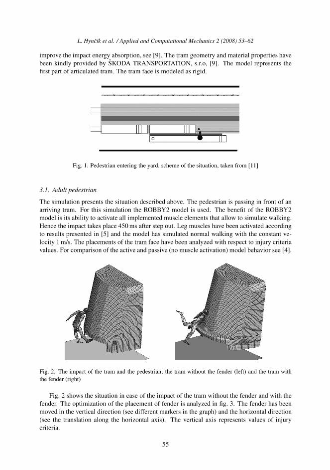
improve the impact energy absorption, see [9]. The tram geometry and material properties havebeen kindly provided by SKODA TRANSPORTATION, s.r.o, [9]. The model represents thefirst part of articulated tram. The tram face is modeled as rigid.
Fig. 1. Pedestrian entering the yard, scheme of the situation, taken from [11]
3.1. Adult pedestrian
The simulation presents the situation described above. The pedestrian is passing in front of anarriving tram. For this simulation the ROBBY2 model is used. The benefit of the ROBBY2model is its ability to activate all implemented muscle elements that allow to simulate walking.Hence the impact takes place 450 ms after step out. Leg muscles have been activated accordingto results presented in [5] and the model has simulated normal walking with the constant ve-locity 1 m/s. The placements of the tram face have been analyzed with respect to injury criteriavalues. For comparison of the active and passive (no muscle activation) model behavior see [4].
Fig. 2. The impact of the tram and the pedestrian; the tram without the fender (left) and the tram withthe fender (right)
Fig. 2 shows the situation in case of the impact of the tram without the fender and with thefender. The optimization of the placement of fender is analyzed in fig. 3. The fender has beenmoved in the vertical direction (see different markers in the graph) and the horizontal direction(see the translation along the horizontal axis). The vertical axis represents values of injurycriteria.
55

L. Hyncık et al. / Applied and Computational Mechanics 2 (2008) 53–62
Fig. 3. Dependence of tram fender placement and values of injury criteria, adult person
It is apparent that the value of head injury criterion always lies under the limit. It is causedby the small impact velocity. The lowest fender seems to be the most responsible for the kneeinjuries. However, there is no situation where all the injury criteria values lie under their limits.Therefore the best seems to be the variant when the fender is placed very low and sticks out ofthe tram face.
3.2. Child
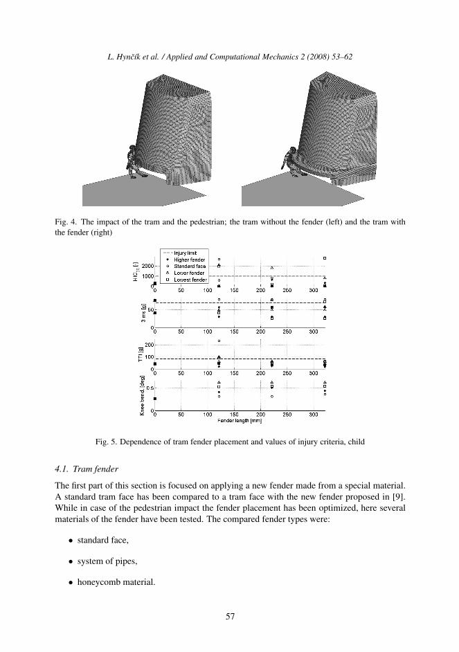
The analysis of child and tram impact has arose from the work presented above. The model ofa six years old child has been created by the virtue of the scaling software, cf. [3]. However,there is a lack of data required to set muscle parameters and therefore the child model hasbeen used as passive — without the muscle activities representing walking. The injuries ofthe child have been also analyzed based on the mentioned injury criteria. Different fenderplacements with respect to constructional possibilities have been again compared to the tramface without the fender. The situation is depicted in fig. 4. The optimization of placement of thefender is analyzed in fig. 5. The fender has moved again in the vertical direction (see differentmarkers in the graph) and the horizontal direction (see the translation along the horizontal axis).The vertical axis represents values of injury criteria. The graph summarizes that more “user-friendly” tram fender with regard to the child pedestrian is that which is placed higher.
4. Driver passive safety
This section is devoted to the enhancement of driver passive safety by proposing a new tramfender and by the use of a safety belt. The fender has been connected to the tram by a transla-tional joint to absorb more kinetic energy. The impact parameters have been set according tothe standards 15227:2005 (E). The back impact has been simulated as the moving tram strokethe standing one. The velocity of the moving tram was 15 km/h.
56
L. Hyncık et al. / Applied and Computational Mechanics 2 (2008) 53–62
Fig. 4. The impact of the tram and the pedestrian; the tram without the fender (left) and the tram withthe fender (right)
Fig. 5. Dependence of tram fender placement and values of injury criteria, child
4.1. Tram fender
The first part of this section is focused on applying a new fender made from a special material.A standard tram face has been compared to a tram face with the new fender proposed in [9].While in case of the pedestrian impact the fender placement has been optimized, here severalmaterials of the fender have been tested. The compared fender types were:
• standard face,
• system of pipes,
• honeycomb material.
57

L. Hyncık et al. / Applied and Computational Mechanics 2 (2008) 53–62
Fig. 6. Fender types; standard (left), piped (middle), honeycomb (right)
In fig. 6 all the tested variants are shown.The evaluation of results is done again according to the injury criteria value. The comparison
of the head acceleration of the driver for different fender types is shown in fig. 7 and fig. 8. Thefirst major peak in fig. 8, left, is caused by the contact between the driver and the frontal desk.This may cause considerable injuries and hence, the driver belt is proposed and discussed later.
Based on the captured signals, the values of the head and thorax injury criteria are computed.They are summarized in tab. 1. The risk for the head injury is lower in case of the honeycombmaterial. On the other hand in case of the pipe fender there is lower thorax injury risk. Generallyit can be summarized that both new materials absorb more energy than the standard fender.
Fig. 7. Comparisson of driver head acceleration for different tram fenders
Table 1. Values of head and thorax injury criteria for different fender types
Standard Piped Honeycomb
HIC36 [–] 217.83 0.69 0.57
3 ms [g] 26.37 7.15 8.67
58

L. Hyncık et al. / Applied and Computational Mechanics 2 (2008) 53–62
Fig. 8. Comparisson of driver thorax acceleration for different tram fenders
4.2. Safety belt
The second part of the section investigates the usage of a two-point safety belt for tram driver.The belt is modeled as a standard car belt, cf. [1]. The only difference is a missing retractorsimilarly as in planes. Fig 9 shows the whole view of the both trams including the driver andpassengers.
Fig. 9. Impacting trams including driver and passengers
The first numerical results (see fig. 10 and fig. 11) show worse situation caused by the useof the driver belt. However, this is caused by the rigid body based human model, becausethe formula for the HIC computation takes all present peaks. The second highest peak iscaused by the contact between the head and thorax since because the belt limits the humanbody motion, the head is pushed much faster forward. This peak seems to be unrealistic sincein biological reality, this contact is not rigid. Hence, the standard filter Sae60 is used to decreasethis unreasonable peak. After this filtering, the use of the belt shows considerable improvementof the driver safety (see tab. 2).
5. Passenger passive safety
In contrast to the previous paragraph, the attention is paid to tram passengers. The same backimpact of the two trams has been analyzed concerning the influence of different tram fenders
59

L. Hyncık et al. / Applied and Computational Mechanics 2 (2008) 53–62
Fig. 10. Comparison of head acceleration for belted and unbelted driver
Fig. 11. Comparison of thorax acceleration for belted and unbelted driver
Table 2. Values of head and thorax injury criteria for unbelted and belted driver
Unbelted driver Belted driver Belted driver, Sae60
HIC36 [-] 217.83 1 142 112.75
3 ms [g] 26.37 22.71 –
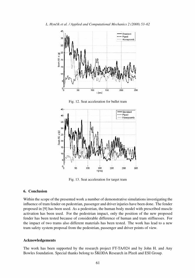
on passengers of the two trams. This influence has been measured by means of the accelerationof a point that was placed on the tram construction near the passenger’s seat.
As expected (see fig. 12 and fig. 13), one can clearly see the improvement of the passengers’safety using the more energy absorbing fender material. Using the standard fender, there is anacceleration peak just in the beginning of the impact. This peak has been avoided using thebetter energy absorbing material. Due to the high noise, the curves are filtered again by thestandard Sae60 filter.
60
L. Hyncık et al. / Applied and Computational Mechanics 2 (2008) 53–62
Fig. 12. Seat acceleration for bullet tram
Fig. 13. Seat acceleration for target tram
6. Conclusion
Within the scope of the presented work a number of demonstrative simulations investigating theinfluence of tram fender on pedestrian, passenger and driver injuries have been done. The fenderproposed in [9] has been used. As a pedestrian, the human body model with prescribed muscleactivation has been used. For the pedestrian impact, only the position of the new proposedfender has been tested because of considerable difference of human and tram stiffnesses. Forthe impact of two trams also different materials has been tested. The work has lead to a newtram safety system proposal from the pedestrian, passenger and driver points of view.
Acknowledgements
The work has been supported by the research project FT-TA/024 and by John H. and AnyBowles foundation. Special thanks belong to SKODA Research in Plzen and ESI Group.
61

L. Hyncık et al. / Applied and Computational Mechanics 2 (2008) 53–62
References
[1] L. Hyncık, Rigid body based human model for crash test purposes, Engeneering Mechanics (5),(2001) 337–342.
[2] L. Hyncık, Knee articulated rigid body model, Proceedings of the Computational Mechanics 2006,Nectiny, University of West Bohemia, 2006, pp. 195–200.
[3] L. Hyncık, V. Novacek, P. Blaha, O. Chvojka, P. Krejcı, On scaling of human body models,Applied and computational mechanics 1 (1) (2007) 63–76.
[4] L. Hyncık, H. Kockova, J. Kovanda, P. Krejcı, On modeling of pedestrian impact, IngeneeringMechanics 1 (15) (2008) 43–55.
[5] H. Kockova, Biomechanical models of living tissues and their industrial applications, Ph.D. thesis,University of West Bohemia, Pilsen, 2007.
[6] H. Kovandova, J. Svoboda, Z. Solc, J. Kovanda, The improvement of pedestrian safety duringtraffic collisions, Czech Technical University in Prague, 2001.http://www2.fs.cvut.cz/web/fileadmin/documents/12241-BOZEK/publikace/2001/paper16-svob.pdf
[7] L. van Rooij, The evaluation of the kinematics of the MADYMO human pedestrian model againstexperimental tests and the influence of a more biofidelic knee joint, 5th MADYMO Users Meetingof the Americas, 2003.http://www.automotive.tno.nl/smartsite.dws?id=626
[8] K. U. Schmitt, P. Niederer, F. Walz, Trauma biomechanics — Introduction to accidental injury,Springer-Verlag, Germany, 2004.
[9] J. Sasek, Navrh deformacnıho narazoveho prvku tramvaje, Diplomova prace, Zapadoceska uni-verzita, Plzen, 2005.
[10] J. Dupal, J. Vimmr, Analyza norem European Standard DRAFT prEN 14363, vyzkumny zpravao resenı projektu c. MPO FT-TA/024 ke dni 31. 12. 2004, Internı dokument, Plzen, 2005.
[11] Konflikt s tramvajı — kazdodennı realita.http://www.cdv.cz/text/archiv/bsp/tramvaje.htm
62