
Optimization of the Spring-Back in Roll Forming Process ... · Optimization of the Spring-Back in...
4
Optimization of the Spring-Back in Roll Forming Process with Finite Element Simulation Ya. Zhang, Ha-Phong. Nguyen, and Dong-Won. Jung Department of Mechanical Engineering, Jeju National University, Jeju, Republic of Korea Email: [email protected], [email protected], [email protected] * Abstract—This study presents a finite model of U-bending roll forming process with COPRA software. Based on the design and simulation of the U-bending’s roll forming process, the bending and spring-back regulations are investigated. A number of U-bending processes are also analyzed in order to determine the springback level. The material used in this roll forming process is Mg-Al alloy. There are many factors which have a significant influence in the forming process, such as the width of the U-bending, the radius of the roll die, lubrication, roll velocity and sheet thickness. In order to predict the performance of the sheet forming process and improve the spring-back, the FEM method and Taguchi method are used in this sheet process design. The sheet with 1, 2 and 3mm thickness pass through 6 stages of bending process. Every stage is uniform with 15° . With three kinds of widths of the U-bending and 3 kinds of radius, there are total 9 simulations are established in this study. The optimal design parameters are obtained with the minimum spring-back angle and the sheet forming quality has been controlled. Index Terms—U bending, spring back, taguchi method, FE simulation I. INTRODUCTION U bending as one kind of cold roll forming now is widely used in metal forming industry and our surrounding environment. AL-Mg steel is widely used in automotive sector, home applications, due to its low cost and easy forming. Zhang Dongjuan established an analysis model based on Hill48 yielding criterion and plane strain condition to predict the spring-back in the U-bending process [1]. You-Min Huang discusses the application of updating Lagrangian elasto-plastic finite element method towards analyzing the sheet metal U-bending process under the plane strain condition [2]. J. R. Cho aims to investigate the spring-back characteristics by numerical method. For the goal, the updated Lagrangian thermo-elasto plastic finite element method was applied to a plane-strain sheet U-bending forming process and the formulation and finite element approximation is also presented [3]. L. C. Sousa presents an optimization method applied to the design of V and U bending sheet metal processes. The method couples the numerical simulation of sheet metal forming processes with an evolutionary genetic Manuscript received March 10, 2016; revised October 15, 2016. algorithm searching the optimal design parameters of the process [4]. Sung Ho Chang investigated the springback characteristics of tailor-welded strips in U-bending processing. Several groups of simulation and experiment developed and the spring back were compared between the experiments and simulations [5]. Bending is the uniform straining of material, usually flat sheet or strip metal, pass through a group of dies along a straight axis. Sheet metal flow within the mold cavity and at last gets the shape according to physics and dimension requirements [6]. The spring back of the U bending is the combine effect of the forming region and informing region. It’s not only depended on the bending method, but also depends on other factors such as die structural and so on. So it is difficult to calculate the spring back with simple math formula. Nowadays, with the advent of computation technology, sheet metal bending process can be analyzed using the finite element method prior to the experiment which depends on the designer’s experience and involve trials and errors to obtain desired result [7]. II. U BENDING The U bending process is shown on the Fig.1. The model is set up with the roll forming. Depending on the shape of the die, the sheet deforms progressively into expected shape we want [8]. With the plastic bending form of the sheet, the elastic deform happen together. After the deformation finish, elastic recovery happened together with the unloaded of the die. This elastic recovery is called spring back. There are many methods to calculate the spring back angle. In this paper, the BISWAS is used to calculate the spring back angle. Figure 1. The U bending model. International Journal of Mechanical Engineering and Robotics Research Vol. 5, No. 4, October 2016 272 © 2016 Int. J. Mech. Eng. Rob. Res. doi: 10.18178/ijmerr.5.4.272-275
Transcript of Optimization of the Spring-Back in Roll Forming Process ... · Optimization of the Spring-Back in...

Optimization of the Spring-Back in Roll Forming
Process with Finite Element Simulation
Ya. Zhang, Ha-Phong. Nguyen, and Dong-Won. Jung
Department of Mechanical Engineering, Jeju National University, Jeju, Republic of Korea
Email: [email protected], [email protected], [email protected]*
Abstract—This study presents a finite model of U-bending
roll forming process with COPRA software. Based on the
design and simulation of the U-bending’s roll forming
process, the bending and spring-back regulations are
investigated. A number of U-bending processes are also
analyzed in order to determine the springback level. The
material used in this roll forming process is Mg-Al alloy.
There are many factors which have a significant influence
in the forming process, such as the width of the U-bending,
the radius of the roll die, lubrication, roll velocity and sheet
thickness. In order to predict the performance of the sheet
forming process and improve the spring-back, the FEM
method and Taguchi method are used in this sheet process
design. The sheet with 1, 2 and 3mm thickness pass
through 6 stages of bending process. Every stage is uniform
with 15°. With three kinds of widths of the U-bending and
3 kinds of radius, there are total 9 simulations are
established in this study. The optimal design parameters
are obtained with the minimum spring-back angle and the
sheet forming quality has been controlled.
Index Terms—U bending, spring back, taguchi method,
FE simulation
I. INTRODUCTION
U bending as one kind of cold roll forming now is
widely used in metal forming industry and our
surrounding environment. AL-Mg steel is widely used in
automotive sector, home applications, due to its low cost
and easy forming.
Zhang Dongjuan established an analysis model based
on Hill48 yielding criterion and plane strain condition to
predict the spring-back in the U-bending process [1].
You-Min Huang discusses the application of updating
Lagrangian elasto-plastic finite element method towards
analyzing the sheet metal U-bending process under the
plane strain condition [2]. J. R. Cho aims to investigate
the spring-back characteristics by numerical method. For
the goal, the updated Lagrangian thermo-elasto plastic
finite element method was applied to a plane-strain sheet
U-bending forming process and the formulation and
finite element approximation is also presented [3]. L. C.
Sousa presents an optimization method applied to the
design of V and U bending sheet metal processes. The
method couples the numerical simulation of sheet metal
forming processes with an evolutionary genetic
Manuscript received March 10, 2016; revised October 15, 2016.
algorithm searching the optimal design parameters of the
process [4]. Sung Ho Chang investigated the springback
characteristics of tailor-welded strips in U-bending
processing. Several groups of simulation and experiment
developed and the spring back were compared between
the experiments and simulations [5]. Bending is the
uniform straining of material, usually flat sheet or strip
metal, pass through a group of dies along a straight axis.
Sheet metal flow within the mold cavity and at last gets
the shape according to physics and dimension
requirements [6]. The spring back of the U bending is
the combine effect of the forming region and informing
region. It’s not only depended on the bending method,
but also depends on other factors such as die structural
and so on. So it is difficult to calculate the spring back
with simple math formula. Nowadays, with the advent of
computation technology, sheet metal bending process
can be analyzed using the finite element method prior to
the experiment which depends on the designer’s
experience and involve trials and errors to obtain desired
result [7].
II. U BENDING
The U bending process is shown on the Fig.1. The
model is set up with the roll forming. Depending on the
shape of the die, the sheet deforms progressively into
expected shape we want [8]. With the plastic bending
form of the sheet, the elastic deform happen together.
After the deformation finish, elastic recovery happened
together with the unloaded of the die. This elastic
recovery is called spring back. There are many methods
to calculate the spring back angle. In this paper, the
BISWAS is used to calculate the spring back angle.
Figure 1. The U bending model.
International Journal of Mechanical Engineering and Robotics Research Vol. 5, No. 4, October 2016
272© 2016 Int. J. Mech. Eng. Rob. Res.doi: 10.18178/ijmerr.5.4.272-275

III. ELEMENT MODEL AND EVALUATION
The investigated material, Al-Mg steel was used in
this design. The Young’s module is 70500N/mm2, the
yield point is 110N/ mm2.The simulation used 6 stations
with finite element software COPRA. The strip width is
calculated with DIN 6935.And every station has a
uniform bending angle of 15 degrees. The flower design
is show in Fig. 2.
Figure 2. The flower design of the u bending
The dimension of the test sample is 100mm width and
300mm longitude. The distance between the stages is
150mm. The simulation calculation method is
Hauschild’s statement and the exponent is 2.5. The
number of surface element along the axis is 32 and cross
axis is 14. The sheet is varied in many types based on
three different thicknesses (1, 2 and 3 mm), three
different radiuses (1.5, 2.5 and 3.5mm) and three
different widths (20, 40 and 60mm). The process is at
room temperature and the roll velocity is not considered
in this process.
The calibrating method used in the COPRA software
is a constant length. It is shown on the Fig. 3; the
bending phenomenon happens with the outer moment. In
the bending region, the sheet at the inner side has been
compressed and the outer side has stretched. Between
the compressed zone and stretched zone, there will be a
layer with a constant length. This layer is called neutral
layer.
Figure 3. The neutral layer of the bending
To conduct the optimization, there are three factors
are applied to the simulation which were the width of the
U bending, radius and sheet thickness as shown in the
Table I.
TABLE I. PROCESS PARAMETERS AND THEIR LEVELS
Symbol Factor Unit Level 1 Level 2 Level 3
A Width mm 20 40 60
B Thickness mm 1 2 3
C Radius mm 1.5 2.5 3.5
For three levels with three factors, there will be totally
23 combinations need to be required. However,
considering about the time while the effect of each factor,
the orthogonal array L3 (33) is chosen to arrange the
simulations. The combination of the simulations is listed
in Table II.
TABLE II. ORTHOGONAL ARRAY
Experiment No.
Parameter Level
A B C
Width Thickness Radius
1 1 1 1
2 1 2 2
3 1 3 3
4 2 1 2
5 2 2 3
6 2 3 1
7 3 1 3
8 3 2 1
9 3 3 2
IV. FINITE ELEMENT MODELING AND RESULTS
The Taguchi method has been applying to the
simulations to optimize the spring back angle. We can
determine the effect of each factor with Signal-to-Noise
(S/N) ratio. Depending on the object of the experiment,
different S/N may be applicable. For this study of spring
back angle in the U bending process, the S/N is “smaller
is better”. The S/N formula is shown on Eq. 1.
2
10
1
1/ 10log [ ]
n
i
i
S N yn
(1)
In the formula, the n is the number of experiment or
simulation repetitions, yi is the simulation or experiment
result, and i stand for the number of design parameters
arranged in the Taguchi orthogonal array (OA).
The S/N and spring back angle is calculated in each
simulation as shown in Table III. According to the
criterion “smaller is better”, the corresponded S/N shows
that the optimum levels are experiment 2 with A1, B3
and C3. The minimum spring back angle will be 1
degree.
TABLE III. COMPARISON OF MEASURED ROUGHNESS DATA
Experiment
No.
Parameter Level Calculated S/N ration
for spring back(DB)
A(mm) B(mm) C(mm) Maximum
spring
back(°)
1 20 1 1.5 1.12 -0.984
2 20 2 2.5 1.03 -0.258
3 20 3 3.5 1.0 0
4 40 1 2.5 1.51 -3.579
5 40 2 3.5 1.22 -1.727
6 40 3 1.5 1.84 -5.296
7 60 1 3.5 1.92 -5.666
8 60 2 1.5 1.87 -5.437
9 60 3 2.5 1.89 -5.527
V. PARAMETER DESIGN AND OPTIMIZATION
The effects of the factors on the spring back were
evaluated from Fig. 4. As a result of the application of
International Journal of Mechanical Engineering and Robotics Research Vol. 5, No. 4, October 2016
273© 2016 Int. J. Mech. Eng. Rob. Res.

Taguchi method, the optimum levels of the factors were
A1, B2 and C3.
Figure 4. Parameter level
The simulation was elaborated with the optimum
factor and the result is shown in the Fig. 5 and Fig. 6.
Fig. 5 showed the strain distribution along the
longitudinal distance with optimized factors. The strain
distributions at first three stages are out of the strain
limited and the strain decreased with the forming process.
From which we can know that the deformation angle at
first three stages are too big and need to be reduced. The
strain at the last three stages although within the strain
limit but still have the tendency to exceed the limitation.
In this situation, an optimization should be come out that
we should increase the forming stages and the forming
angels also need to reduce. In the Fig. 6, the plastic
strain of the sheet along the longitudinal seems to
increase with the roll forming process and the residual
strain is up to 0.65%.
Figure 5. The strain distribution along the longitudinal distance
Figure 6. The plastic strain distribution along the longitudinal distance
Fig. 7 shows the spring back angle with the optimized
factor. The spring back angle of the optimum factors is
1.22 degree. By using the Taguchi method as above, the
spring back angle has been reduced. This result is
obviously larger than the combination simulations we
did. This is because the factors we considered are not
enough. These factors have no significant influence on
the spring back. Which means more factors and
combinations need to apply to the optimize process.
Figure 7. The spring back angel with the optimized factor
VI. THE SENSITIVITY STUDY OF THE FACTORS
The sensitivity study is a kind of method to analysis
the most sensitive factor among groups of uncertainties.
And predict the influence of the factors on the results.
We can divide the method into univariate sensitivity
analysis multivariate sensitivity analysis according to the
number of the varieties. In this paper, the univariate
sensitivity has been used to analysis the sensitivity of the
three factors. The changes will reference to the spring
back angle when the width is 40mm, thickness is 2mm
and the radius is 2.5mm. The spring back angel under
the circumstances above is 1.06 degree. The sensitivity
intervals and results are shown in Table IV. From which
we can know that the thickness is the most sensitivity
factor among the three parameters. The width of the
sheet has the smallest influence on the spring back.
TABLE IV. THE SENSITIVITY ANALYSIS
Experiment
No. Factor interval
Spring back angle
interval
1 Width -50% +50% -2.9% 2.9%
2 Thickness -50% +50% -16.3% 42.4%
3 radius -66% +66% -11.6% 15.1%
VII. VERIFICATION
A U bending experiment has been set up to verify the
simulation result. As shown in the Fig. 8, the roll
forming machine with 4 stages of rolls has been set up
and the deformation angle for each step is constant. The
deformation angle for each stage is 22.5 degree. The
distance between the stages is 220mm. We can control
the gap of the rolls by the screw nut above the mills.
Figure 8. The roll forming machines
a Young’s module is 70500N/mm2 and the yield point is
251N/ mm2. The thickness of the sheet is 1mm and the
radius of the roll is 5mm. The final width of the sheet is
20mm. The experiment result is shown in the Fig. 9.
International Journal of Mechanical Engineering and Robotics Research Vol. 5, No. 4, October 2016
274© 2016 Int. J. Mech. Eng. Rob. Res.
EXPERIMENTAL
The material used in this experiment is mild steel with
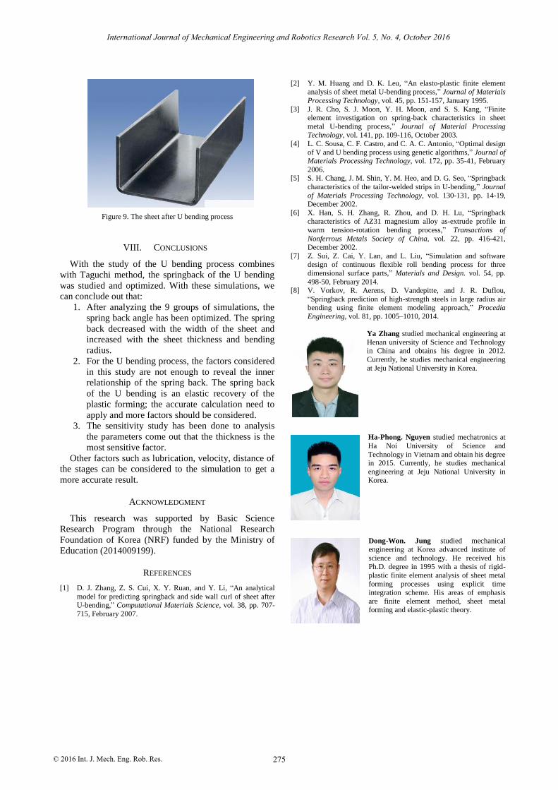
Figure 9. The sheet after U bending process
VIII. CONCLUSIONS
With the study of the U bending process combines
with Taguchi method, the springback of the U bending
was studied and optimized. With these simulations, we
can conclude out that:
1. After analyzing the 9 groups of simulations, the
spring back angle has been optimized. The spring
back decreased with the width of the sheet and
increased with the sheet thickness and bending
radius.
2. For the U bending process, the factors considered
in this study are not enough to reveal the inner
relationship of the spring back. The spring back
of the U bending is an elastic recovery of the
plastic forming; the accurate calculation need to
apply and more factors should be considered.
3. The sensitivity study has been done to analysis
the parameters come out that the thickness is the
most sensitive factor.
Other factors such as lubrication, velocity, distance of
the stages can be considered to the simulation to get a
more accurate result.
ACKNOWLEDGMENT
This research was supported by Basic Science
Research Program through the National Research
Foundation of Korea (NRF) funded by the Ministry of
Education (2014009199).
REFERENCES
[1] D. J. Zhang, Z. S. Cui, X. Y. Ruan, and Y. Li, “An analytical
model for predicting springback and side wall curl of sheet after U-bending,” Computational Materials Science, vol. 38, pp. 707-
715, February 2007.
[2] Y. M. Huang and D. K. Leu, “An elasto-plastic finite element analysis of sheet metal U-bending process,” Journal of Materials
Processing Technology, vol. 45, pp. 151-157, January 1995.
[3] J. R. Cho, S. J. Moon, Y. H. Moon, and S. S. Kang, “Finite element investigation on spring-back characteristics in sheet
metal U-bending process,” Journal of Material Processing Technology, vol. 141, pp. 109-116, October 2003.
[4] L. C. Sousa, C. F. Castro, and C. A. C. Antonio, “Optimal design
of V and U bending process using genetic algorithms,” Journal of Materials Processing Technology, vol. 172, pp. 35-41, February
2006. [5] S. H. Chang, J. M. Shin, Y. M. Heo, and D. G. Seo, “Springback
characteristics of the tailor-welded strips in U-bending,” Journal
of Materials Processing Technology, vol. 130-131, pp. 14-19, December 2002.
[6] X. Han, S. H. Zhang, R. Zhou, and D. H. Lu, “Springback characteristics of AZ31 magnesium alloy as-extrude profile in
warm tension-rotation bending process,” Transactions of
Nonferrous Metals Society of China, vol. 22, pp. 416-421, December 2002.
[7] Z. Sui, Z. Cai, Y. Lan, and L. Liu, “Simulation and software design of continuous flexible roll bending process for three
dimensional surface parts,” Materials and Design. vol. 54, pp.
498-50, February 2014. [8] V. Vorkov, R. Aerens, D. Vandepitte, and J. R. Duflou,
“Springback prediction of high-strength steels in large radius air bending using finite element modeling approach,” Procedia
Engineering, vol. 81, pp. 1005–1010, 2014.
Ya Zhang studied mechanical engineering at
Henan university of Science and Technology in China and obtains his degree in 2012.
Currently, he studies mechanical engineering
at Jeju National University in Korea.
Ha-Phong. Nguyen studied mechatronics at
Ha Noi University of Science and
Technology in Vietnam and obtain his degree in 2015. Currently, he studies mechanical
engineering at Jeju National University in Korea.
Dong-Won. Jung studied mechanical engineering at Korea advanced institute of
science and technology. He received his Ph.D. degree in 1995 with a thesis of rigid-
plastic finite element analysis of sheet metal
forming processes using explicit time integration scheme. His areas of emphasis
are finite element method, sheet metal forming and elastic-plastic theory.
International Journal of Mechanical Engineering and Robotics Research Vol. 5, No. 4, October 2016
275© 2016 Int. J. Mech. Eng. Rob. Res.