
Optimization of Microstrip Ring UWB filter using ANN-PSO · Optimization of Microstrip Ring UWB...
13
International Journal of Scientific and Research Publications, Volume 3, Issue 8, August 2013 1 ISSN 2250-3153 www.ijsrp.org Optimization of Microstrip Ring UWB filter using ANN- PSO Manidipa Nath AIACTR, Delhi [email protected] Abstract- Ultra-Wide Band (UWB) is promising technology for many wireless applications due to its large bandwidth, good ratio of transmission data and low power cost. The main goal of this work is to design an UWB filter suitable for that purpose in the frequency band 3.1-10.6 GHz. In order to achieve that goal, one UWB filter configuration is investigated, designed and characterized. Theoretical analysis is done to compute the filter parameters, such as the return loss, insertion loss and attenuation characteristic over the full frequency band. The size of this filter is also studied because of its important aspect on the frequency behavior. Index Terms- UWB, filter, frequency response, insertion loss, return loss. I. INTRODUCTION UWB technology is promising and attractive for local area networks, position location, tracking and radar systems. The technology has the characteristics of low cost, high data transmission rate and very low power consumption. Many UWB devices and circuits are proposed and investigated widely [1-5]. It is important to reduce their size and weight in order to integrate them with other components as a compact system. Compact and broadband bandpass filter (BPF) is a key passive component and highly demanded in a UWB system. A planar BPF based on a microstrip structure can provide the advantages of easy design, low cost, compact size. A microstrip BPF widely used in a variety of RF/microwave and millimeterwave systems and compact UWB microstrip BPF can be used in a UWB communication system. UWB filters should have a fractional bandwidth of more than 70.0% and it is very difficult to achieve such a wide passband with a traditional parallel-coupled transmission line structures. A practical requirement exists for UWB BPF with a strong coupling structure that can be easily realized and fabricated. A ring shaped microstrip resonator circuit with quarter wavelength short circuited stub is analyzed using EM theory and resulting dimensions are utilized to design a single section of an UWB filter in the desired frequency range. Consequently five such circular ring resonators are designed and successive stages are coupled using interconnected lines. Here proper tuning stub is used to implement a strong coupling between the input/output port and the resonator. Thus an UWB microstrip BPF with low loss is designed and further optimized for best achievable frequency response. After the release of UWB bandpass filters with a passband of the same frequency range (3.1 GHz -10.6 GHz, a fractional bandwidth of 110%) were challenges for conventional filter designs. Before mid 2003 the bandwidth of the passband for a bandpass filters was extended from 40% to 70% [2]. These filters are named as broad bandpass filters.
Transcript of Optimization of Microstrip Ring UWB filter using ANN-PSO · Optimization of Microstrip Ring UWB...

International Journal of Scientific and Research Publications, Volume 3, Issue 8, August 2013 1 ISSN 2250-3153
www.ijsrp.org
Optimization of Microstrip Ring UWB filter using ANN-
PSO
Manidipa Nath
AIACTR, Delhi
Abstract- Ultra-Wide Band (UWB) is promising technology for many wireless applications due to its large bandwidth,
good ratio of transmission data and low power cost. The main goal of this work is to design an UWB filter suitable for
that purpose in the frequency band 3.1-10.6 GHz. In order to achieve that goal, one UWB filter configuration is
investigated, designed and characterized. Theoretical analysis is done to compute the filter parameters, such as the return
loss, insertion loss and attenuation characteristic over the full frequency band. The size of this filter is also studied because
of its important aspect on the frequency behavior.
Index Terms- UWB, filter, frequency response, insertion loss, return loss.
I. INTRODUCTION
UWB technology is promising and attractive for local area networks, position location, tracking and radar systems.
The technology has the characteristics of low cost, high data transmission rate and very low power consumption. Many
UWB devices and circuits are proposed and investigated widely [1-5].
It is important to reduce their size and weight in order to integrate them with other components as a compact
system. Compact and broadband bandpass filter (BPF) is a key passive component and highly demanded in a UWB
system. A planar BPF based on a microstrip structure can provide the advantages of easy design, low cost, compact size.
A microstrip BPF widely used in a variety of RF/microwave and millimeterwave systems and compact UWB
microstrip BPF can be used in a UWB communication system. UWB filters should have a fractional bandwidth of more
than 70.0% and it is very difficult to achieve such a wide passband with a traditional parallel-coupled transmission line
structures. A practical requirement exists for UWB BPF with a strong coupling structure that can be easily realized and
fabricated.
A ring shaped microstrip resonator circuit with quarter wavelength short circuited stub is analyzed using EM
theory and resulting dimensions are utilized to design a single section of an UWB filter in the desired frequency range.
Consequently five such circular ring resonators are designed and successive stages are coupled using interconnected lines.
Here proper tuning stub is used to implement a strong coupling between the input/output port and the resonator. Thus an
UWB microstrip BPF with low loss is designed and further optimized for best achievable frequency response.
After the release of UWB bandpass filters with a passband of the same frequency range (3.1 GHz -10.6 GHz, a
fractional bandwidth of 110%) were challenges for conventional filter designs. Before mid 2003 the bandwidth of the
passband for a bandpass filters was extended from 40% to 70% [2]. These filters are named as broad bandpass filters.

International Journal of Scientific and Research Publications, Volume 3, Issue 8, August 2013 2 ISSN 2250-3153
www.ijsrp.org
They were not covering the whole UWB frequency range. In [3] a bandpass filter covering the whole UWB frequency
range with a fractional bandwidth of 110% was realized by fabrication signal lines on a lossy composite substrate. A
successful transmission of the UWB pulse signal was demonstrated using the proposed bandpass filter. This is one of the
early reported filters that possess an ultra-wide passband. However, it has a high insertion loss in the passband due to the
lossy substrate. Not much research work was reported in 2003 and 2004. In 2004, a ring resonator with a stub was
proposed which shows a bandwidth of 86.6% [4]. A bandpass filter covering the whole UWB frequency band was a
challenge for microwave filter designers and researchers in that period of time. There are mainly four types of structures
that are able to realize an ultra-wide passband.
II. UWB FILTER CONFIGURATION
UWB was originally developed for military communications and radar. In the field of UWB technology different
methods and structures [2- 6] has pushed development of new UWB filters.
Lumped-element filter design is generally unpopular due to the difficulty of its use at microwave frequencies
along with the limitations of lumped element values. Hence conventional microstrip filters are often used. The new
proposed filter design is based on ring resonators having quarter wavelength short-circuited stub and realized in microstrip
configuration.
The paper focuses on systematic design and realization of an UWB in printed circuit configuration. The filter
design is done with ring shaped resonator and realized in microstrip configuration. The diameter of the ring is designed
according to the frequency requirements and stub matching is used to tune the filter to the desired band of operation. Stub
width and ring diameter, inter ring separation is taken as design parameter to optimize its frequency response
performance. It is designed as per FCC recommended band from 3.1-10.6 GHz.
Figure 1. Ring resonator configuration as filter
III. UWB FILTER DESIGN PROCESS
The UWB is designed using ANN model of ring resonator and PSO optimization techniques. Here Artificial
Neural Network (ANN) and Particle Swarm Optimization (PSO) algorithm is used for the synthesis of the UWB filter
using ring resonator. The PSO algorithm is used to optimize the filter geometry i n order to obtain a wideband
performance of the microstrip filter. The configuration of the ring structure acting as resonator is shown in Figure 1.
whose resonance frequency is controlled by a tuning stub. The stub dimensions are fed as input to a trained ANN to
model the reflectance and transmittance of the single ring resonator. In this work micro strip substrate is used in order to
realize the filter using ring structure (substrate thickness 10 mil, dielectric constant 9.8). Analysis using method of

International Journal of Scientific and Research Publications, Volume 3, Issue 8, August 2013 3 ISSN 2250-3153
www.ijsrp.org
moment and further simulation using commercial software tools is performed to investigate and verify the performance of
the ring filter. The EM simulation results are in good agreement with those obtained using the ANN algorithm. The
objective of this work is to use the ANN model coupled with the particle swarm optimization (PSO) algorithm to
synthesize the UWB filter using multiple rings and optimize its performance as UWB filter. In this design, successive
stages of coupled circular ring structure with proper tuning stub is used to implement strong coupling between the
input/output port and the resonator.
Figure 2. Measured results of reflectance and transmittance of a single ring microstrip filter
Figure 3. UWB filter configuration using ring structure
The EM simulation tools are used to optimize the frequency response performance of this UWB filter. Simulated results
predict performance of the filter as per FCC Standard. It is observed that the design dimensions are critical in deciding the
filter responses. The ring dimension and stub width are required to be precise for the microstrip filter under concern as per
optimized results to meet the specification.Final pcb design is generated based on the optimized design for the multiple
ring resonator structure with connecting lines. The filter hardware based on the optimized design is fabricated and
measured to verify the UWB performance over the FCC band. The filter under concern is designed to provide an Insertion
Loss ≤ 1 dB and average roll off 30 dB/decade. The measurement results are quite encouraging.

International Journal of Scientific and Research Publications, Volume 3, Issue 8, August 2013 4 ISSN 2250-3153
www.ijsrp.org
Figure 4. Layout of the UWB ring
Figure 5. 3D model of UWB filter for simulation
The new proposed design of ring filter is associated with a quarter wavelength short-circuited stub for frequency
tuning. Five sections are combined and optimized using PSO for its best achievable filter performance in the UWB
frequency range from 3.1-10.6 GHz. A systematic design and realization of an UWB filter in microstrip configuration is
done using stub tuned ring shaped resonator having single input and single output. The diameter of the ring is designed
according to the resonating frequency requirements and stub matching is used to tune the filter to the desired band of
operation. Stub width, ring diameter, inter ring separation is taken as design parameter for ANN model of each section of
the ring. Five such sections are modeled using ANN to cover the whole UWB range and combined to form the integrated
ring filter whose S parameters are computed using theory and verified by MOM simulation tools (IE3D). The reflectance
and transmittance of the whole filter is optimized using PSO for FCC recommended band from 3.1-10.6 GHz.
III. THEORY OF RING RESONATOR
The theoretical investigation and analysis is done to relate the geometry parameters of the ring
with its S parameters. Method of moments analysis in the spectral domain in conjunction with the Mixed-
Potential Integral Equation (MPIE) approach is used by transforming the expansion and weighting functions [7-8]. Using
the decomposition of Green’s functions, the method of moment matrix entries can be reduced to a sum of two integrals.
The first one is expressed in the spatial field and corresponds to the quasi-static contribution. It is analytically evaluated
with the exponential terms in the function to be integrated. The integrals expressed in the spectral field and
corresponding to the dynamic part have the advantage of being calculated on a finite range and this is independent of the

International Journal of Scientific and Research Publications, Volume 3, Issue 8, August 2013 5 ISSN 2250-3153
www.ijsrp.org
choice of the basis and test functions. The integrals expressed in the spectral field are performed by using numerical
integration [9-12]. The formulation begins with the development of an integral expression which defines the electric field
resulting from an arbitrary current distribution. This integral expression employes a Green’s function which relates the
electric field at an arbitrary observation point to the current at an arbitrary source point. The MOM applies orthogonal
expansions to translate the integral equation into a system of circuit-like simultaneous linear equations. Appropriate basis
functions are used to expand the current distribution. Testing functions are used to invoke the electric field boundary
conditions. Matrix methods are then used to solve for the expansion coefficients associated with the basis functions. The
current distribution solution is then constructed from the expansion coefficients.
The MOM simulation tools (IE3D) are used to verify the performance of this filter in terms of S11 and S12 of this
optimized wideband ring filter. It is observed that the design dimensions are critical in deciding the filter responses. The
ring dimension and stub width are optimized to meet the specification and accordingly final PCB design is generated. The
UWB filter is designed to provide an insertion loss ≤ 1 dB and average roll off of 30 dB / decade. Simulated results
predict performances of the filter as per FCC Standards are shown in Figure 2. The filter based on the optimized design is
fabricated and tested. The measurement results are quite encouraging.
IV. DESIGN OF RING FILTER
An exact analysis of the structure is very tedious. Hence a synthesis procedure is followed which involves a
number of simplifying approximations that permit straightforward, easy to-use design calculations [13-16]. However these
approximate design equations are found to be sufficiently accurate for most practical applications. The filter design is
based on ring structure with quarter wavelength short-circuited stubs [17-22]. Here five short circuited stubs are designed
for a distributed microstrip ring band pass filter whose connecting lines are non-redundant. In order to reduce the filter
size the length of the connecting line are optimized. The characteristic impedances of these short-circuited stubs and the
characteristic impedances of the connecting lines are chosen at 3.1 GHz. The dimension of the individual ring and its stub
line impedance is computed using MOM considering fundamental resonance [23-30].
V. ANN MODEL OF RING FILTER
A training set of 670 randomly distributed points of the parameters in the range given in table I. The back-
propagation t raining algori thm along with the sigmoid function as the act ivat ion function is used for the feed-
forward network of the ANN in order to train it. Five sections of the ring resonators with controlling stubs are used to
develop the full UWB ring filter. A three layer ANN with a hidden layer having 16 neurons is used to successfully
model the geometry parameters of the ring such as diameter of the ring, characteristic impedance of the ring structure,
inter ring separation and stub dimensions of individual ring to decide different resonance frequencies covering the UWB
band. The training and testing data set is generated from the results of the analysis of the ring structure using method of
moments. The accuracy of the trained network with this architecture is given in table II in terms of average error and
standard deviation. Therefore, for a given set of input parameters, the geometry parameters of the ring can be accurately
computed in the frequency range of interest in negligible time using the developed ANN.

International Journal of Scientific and Research Publications, Volume 3, Issue 8, August 2013 6 ISSN 2250-3153
www.ijsrp.org
VI. DEVELOPMENT OF UWB FILTER
The individual ring structure with microstrip line stub having extended ground plane is designed and simulated
using IE3D for verification of the frequency response. The single ring filter structure is fabricated and impedance
bandwidth is measured as shown in Figure 2(considering fundamental and harmonic frequencies). The measured result
shows a frequency bandwidth of 1.3 GHz (8.0 GHz - 9.3GHz) with an insertion loss of 2.7 dB (average). Five such
sections covering the whole UWB band is designed and integrated to form the UWB filter as shown in Figure 3 and 4 . It
is observed that the integrated five section ring filter can be used for FCC regulated UWB operations where bandwidth
enhancement of 150.0% or more is possible. Simulation model of the ring filter is shown in figure 5 and the frequency
response of the five section ring filter is verified using MOM simulator for UWB operation as shown in figure 6.
Figure 6. Simulated reflection & transmission characteristics of the UWB filter having five integrated ring in
microstrip configuration.
VII. PSO FITNESS FUNCTION
The reflectance and transmittance of the whole filter is optimized using PSO for FCC recommended
UWB band from 3.1-10.6 GHz. The reflectance and transmittance of the integrated ring filter having five
sections with different stub width and length are fed to PSO for bandwidth optimization of the same. A suitable
fitness function for PSO is used considering maximum bandwidth and minimum return loss of the micro
strip ring filter and is shown below.
Fitness =
N
i
i
N
i
i RT11
Ti=max ),( 2121 DiSS
Si=min ),( 1111 DiSS
3 4 5 6 7 8 9 10-60
-50
-40
-30
-20
-10
0
Frequency in GHz.
Sim
ula
ted
S p
aram
ete
r(d
B)
Simulated filter response ( S parameter) of microstrip UWB structure
S21
S11

International Journal of Scientific and Research Publications, Volume 3, Issue 8, August 2013 7 ISSN 2250-3153
www.ijsrp.org
iT = D
S21 Di
SS 2121 &Di
SS 2121
),min( 2121Di
SS otherwise
iR = D
S11 Di
SS 1111
- iS -Ki
iSSD 11
otherwise
Where the subscript i indicates different
n frequency points. N indicates the total number of simulated frequency points. D
S11 (in dB), D
S21 (in dB) are the
design requirements for 11S and 21S respectively. The sign indicates that this operation is taken as soon as
this condition is satisfied at all frequencies. iK is set to 1 for all test cases in order to reach an equally weighted
sum of reflection coefficient and transmission coefficient. The possible maximum sum of all iR is -D
S11 *N. It
can be achieved if all 11S i are smaller than D
S11 . The PSO algorithm is converged within 50 iterations with
sufficient accuracy (Figure 7.). The optimized dimensions of the stubs controlling the resonance frequency of
individual rings are used to fabricate the UWB filter and the frequency response of the same is also verified from
MOM simulator. The optimized dimensions of geometrical parameters of the five section ring filter are tabulated
in table III. The fabricated ring filter is shown in Figure 8.
The MOM simulation tools (IE3D) are used to verify the performance of this filter in terms of 11S and 21S of
this optimized wideband ring filter. It is observed that the design dimensions are critical in deciding the filter responses.
The ring dimension and stub width are optimized to meet the specification and accordingly final PCB design is generated.
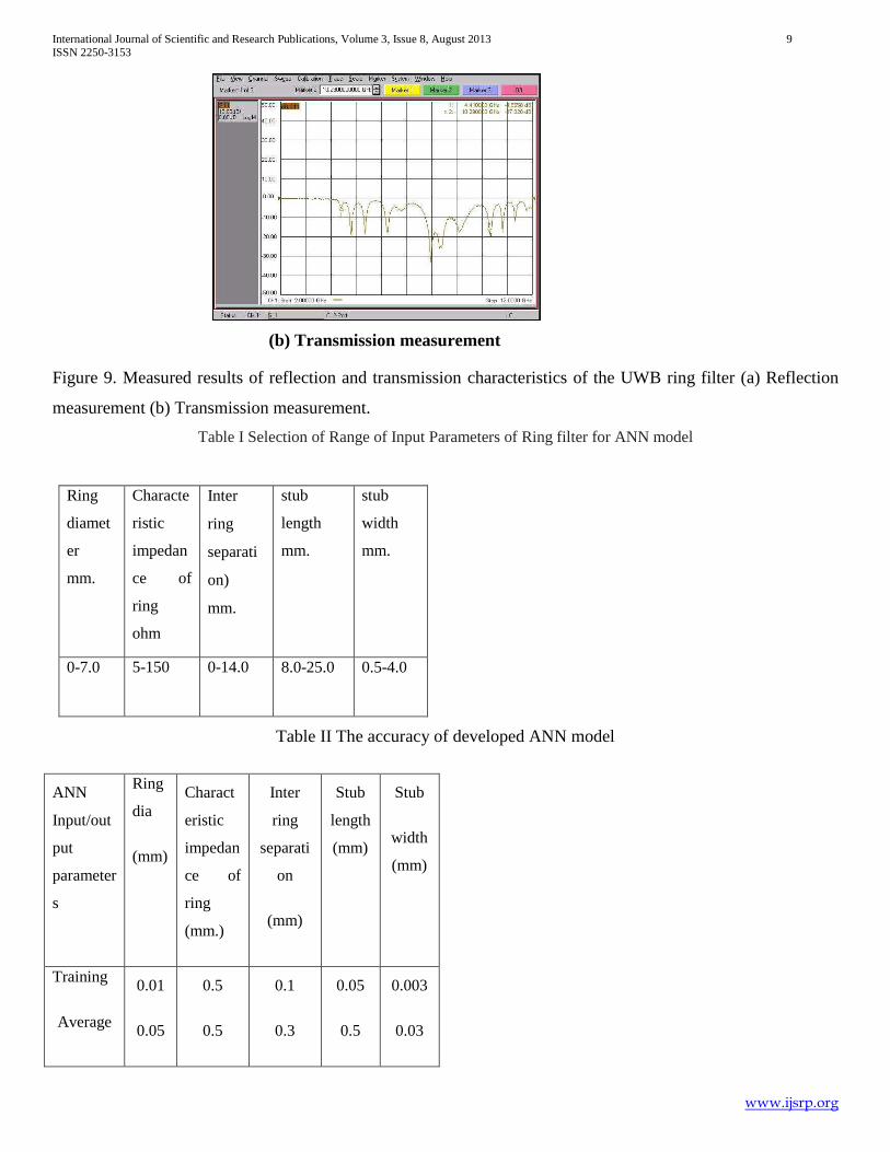
VIII. MEASUREMENT
The final filter layout is generated and fabricated using CER-10 using optimized dimension of the geometry
parameters with best possible fabrication precession available. The final circuit after integration and packaging
undergone for testing. The fabricated filter is measured for transmission and reflection performance with the help of
Network Analyzer (E8363B). The measured attenuation and VSWR plot of the filter is shown in Figure (9.a-b).
Measurement results shows good filter characteristic over the whole UWB band. The measured insertion loss over the
band is 3.0 dB (average) and a 7.3 GHz filter passband from 4.41-10.29 GHz. with -10 dB return loss, and VSWR band
width of 6.5 GHz is obtained. Measured results are compared with that of the simulated performance as shown in table
IV. These results have indicated a very good agreement between simulation and measurements. This insertion loss can be
further reduced using low loss substrate and SMA connectors. The fabrication process is required to be precise to improve
this loss figure and to realize the full bandwidth for UWB operations. The mounting of the filters is required be rigid and
full flatness of the substrate should be ensured to avoid surface wave loss. The other performance is seen to be
satisfactory.

International Journal of Scientific and Research Publications, Volume 3, Issue 8, August 2013 8 ISSN 2250-3153
www.ijsrp.org
Figure 7. PSO convergence plot
Figure 8. Fabricated ring filter in microstrip configuration.
(a) Reflection measurement
International Journal of Scientific and Research Publications, Volume 3, Issue 8, August 2013 9 ISSN 2250-3153
www.ijsrp.org
(b) Transmission measurement
Figure 9. Measured results of reflection and transmission characteristics of the UWB ring filter (a) Reflection
measurement (b) Transmission measurement.
Table I Selection of Range of Input Parameters of Ring filter for ANN model
Ring
diamet
er
mm.
Characte
ristic
impedan
ce of
ring
ohm
Inter
ring
separati
on)
mm.
stub
length
mm.
stub
width
mm.
0-7.0 5-150 0-14.0 8.0-25.0
0.5-4.0
Table II The accuracy of developed ANN model
ANN
Input/out
put
parameter
s
Ring
dia
(mm)
Charact
eristic
impedan
ce of
ring
(mm.)
Inter
ring
separati
on
(mm)
Stub
length
(mm)
Stub
width
(mm)
Training
Average
0.01
0.05
0.5
0.5
0.1
0.3
0.05
0.5
0.003
0.03

International Journal of Scientific and Research Publications, Volume 3, Issue 8, August 2013 10 ISSN 2250-3153
www.ijsrp.org
error
Testing
Average
error
0.02
0.04
0.7
0.6
0.2
0.4
0.06
0.4
0.004
0.04
Table III Optimized dimensions of the ring filter (ANN-PSO model)
Ring
diam
eter)
mm.
Charact
eristic
impeda
nce of
ring in
ohm
Inter ring
separatio
n in mm.
stub
length
mm.
stub
width
mm.
5.6 50.0 10.0 S1 8.5
S2 8.1
S3 8.0
S4 7.95
S5 7.8
S1 2.0
S2 3.03
S3 5.73
S4 6.23
S5 8.2
Table IV Comparison table of the simulated and measured performance of the UWB ring filter
Filter Parameter Simulated Measured
VSWR Bandwidth 5..8 GHz 5.88 GHz
Insertion loss 4 dB 3.0 dB(avg.)
CONCLUSIONS

International Journal of Scientific and Research Publications, Volume 3, Issue 8, August 2013 11 ISSN 2250-3153
www.ijsrp.org
In this chapter an UWB microstrip BPF with low insertion loss is designed and optimized for its frequency
response performance using PSO. Each individual ring resonator is associated with a quarter wavelength short-circuited
stub for frequency tuning. A systematic design and realization of an UWB filter in printed circuit configuration is done
using stub tuned ring shaped microstrip structure having single input and single output. The diameter of the ring is chosen
according to the resonating frequency requirements and stub matching is used to tune the filter to the desired band of
operation. Stub width, ring diameter, inter ring separation is taken as input design parameter for the ANN model. Five
different ring resonators are integrated to form UWB filter where the geometrical parameters of the individual ring
resonators are obtained from output of respective ANN model. Five sections are combined and optimized using PSO
where reflectance and transmittance of the integrated microstrip ring filter is optimized for UWB frequency range from
3.1-10.6 GHz. In this process of optimization the physical dimensions of individual rings are altered and the filter as a
whole becomes capable of efficient transmission for UWB band. Finally the final filter layout is generated and
fabricated using optimized dimensions of the ring structure with best possible fabrication precession available. The S
parameters of the fabricated filter is measured to verify the transmission and reflection performance of the same with the
help of VNA and compared with that of the simulated performance as shown in table IV. These results have indicated a
very good agreement between simulation and measurements.
So it can be concluded that ANN-PSO technique is efficiently utilized for design and development of one UWB
filter having optimum frequency response. The insertion loss and measured bandwidth are near to that of the desired value
and can be improved further with some precautions.
REFERENCES
1. A. Saito, H. Harada, and A. Nishikata,“Development of Band Pass Filter for Ultra Wideband (UWB) Communication
Systems,”International Microwave Symposium, Philadelphia, Pennsylvania, USA, June 2003.
2. H. Ishida and K. Araki, “A Design of tunable UWB Filters” International Microwave Symposium, Fort Worth, Texas,
USA, June 2004.
3 L. Zhu, S. Sun, and W. Menzel "Ultra-wideband (UWB) Bandpass Filters Using Multiple-Mode Resonator", IEEE
Microwave and Wireless Components Letters, Vol. 15, No.11, November 2005, pp.796-798.
4. H. Wang and L. Zhu, "Ultra-wideband Bandpass Filter Using Back-to-back
Microstrip-to-CPW Transition Structure", Electronic Letters, Vol. 41, No.24, November 2005.
5. K. Li, D. Kurita, and T. Matsui, “An Ultra- Wideband Bandpass Filter Using Broadside-Coupled Microstrip-Coplanar
Waveguide Structure,” International Microwave Symposium, Long Beach, CA, USA, June 2005.
6. C. Hsu, F. Hsu, and J. Kuo, “Microstrip Bandpass Filters for Ultra-Wideband (UWB) Wireless Communications,”
International Microwave Symposium, Long Beach, CA, USA, June 2005.
7. C. Tang, C. Tseng, H. Liang, and S. You, “Development of Ultra-wideband LTCC Filter,” IEEE International
Conference on Ultra-Wideband, Zurich, Switzerland, September, 2005.
8. S. Sun, and L. Zhu, "Capacitive-Ended Interdigital Coupled Lines for UWB Bandpass Filters with Improved Out-of-
Band Performances", IEEE Microwave and Wireless Components Letters, Vol. 16, No.8, August 2006, pp.440-442.

International Journal of Scientific and Research Publications, Volume 3, Issue 8, August 2013 12 ISSN 2250-3153
www.ijsrp.org
9. G. M. Yang, R. H. Jin, and J. P. Geng, "Planar Microstrip UWB Bandpass Filter Using U-shaped Slot Coupling
Structure", Electronic Letters, Vol. 42,No.25, December 2006.
10. R. Gomex-Garcia, and J. Alonso, "Systematic Method for the Exact Synthesis of Ultra-Wideband Filtering Responses
Using High-Pass and Low-Pass Sections", IEEE Trans. on Microw. Theory and Tech., Vol. 54, No 10, October 2006,
pp.3751-3764.
11. P. Cai, Z. Ma, X. Guan, Y. Kobayashi, T. Anada, and G. Hagiwara, “Synthesis and Realization of Novel Ultra-
Wideband Bandpass Filters Using Wavelength Parallel-Coupled Line Resonators”, Asia-Pacific Microwave Conference,
Japan,December, 2006.
12. D. Kaddour, J. Arnould, and P. Ferrari, “Design of a Miniaturized Ultra Wideband Bandpass Filter Based on a Hybrid
Lumped Capacitors – Distributed Transmission Line Topology”, 36th European Microwave Conference, Manchester, UK,
September, 2006.
13. D. Packiaraj, M. Ramech, and A. T. Kalghatgi, “Broad Band Filter for UWB Communications”, 36th European
Microwave Conference, Manchester, UK, September, 2006.
14. H. Shaman and J. Hong, “A Compact Ultra- Wideband (UWB) Bandpass Filter with Transmission Zero”, 36th
European Microwave Conference, Manchester, UK, September, 2006.
15. H. Shaman and J. Hong, "Ultra-Wideband (UWB) Bandpass Filter with Embedded Band Notch Structure", IEEE
Microwave and Wireless Components Letters, Vol. 17, No.3, March 2007, pp.193-195.
16. K. Li, D. Kurita, and T. Matsui, “Dual-Band Ultra-Wideband Bandpass Filter,” International
Microwave Symposium, San Francisco, California, USA, June 2006.
17. H. Shaman and J. Hong, "Asymmetric Parallel- Coupled Lines for Notch Implementation in UWB Filters", IEEE
Microwave and Wireless Components Letters, Vol. 17, No.7, July 2007, pp.516-518.
18. Saito, A., H. Harada, and A. Nishikata, Development of band pass fillter for ultra wideband (UWB) communication
systems," Proc. IEEE Conf. Ultra Wideband Systems and Technology, 76-80, 2003.
19. Ishida, H. and K. Araki, Design and analysis of UWB band pass fillter with ring filter," IEEE MTT-S Int. Dig., 1307-
1310, Jun. 2004.
20Chin, K., L. Lin, and J. Kuo, New formulas for synthesizing microstrip bandpass filters withrelatively wide
bandwidths," IEEE Microwave and Guided Wave Letters, Vol. 14, No. 5, 231-233, Mar. 2004.
22. Li, K., D. Kurita, and T. Matsui, An ultrawideband bandpass filter using broadside-coupledicrostrip-coplanar
waveguide structure," IEEE MTT-S Int. Dig., 657-678, Jun. 2005.
23. Hsu, C.-L., F.-C. Hsu, and J.-T. Kuo, Microstrip bandpass filters for ultra-wideband (UWB) wireless
communications," IEEE MTT-S Int. Dig., 679-682, Jun. 2005.
24. Pozar, D. M., Microwave Engineering, 2nd Ed., John Wiley & Sons, New York, 1998.
25. Hong, J. S. and H. Shaman, An optimum ultrawideband microstrip filter," Microw. Opt. Technol. Lett., Vol. 47, No.
3, 230-233, Nov. 2005.
26. Hong, J. S. and H. Shaman, An optimum ultrawideband bandpass filter with spurious re-sponse suppression," IEEE
WAMICON, 1-5, Dec. 2006.

International Journal of Scientific and Research Publications, Volume 3, Issue 8, August 2013 13 ISSN 2250-3153
www.ijsrp.org
27. Hong, J. S. and H. Shaman, A compact ulrtrawideband (UWB) bandpass filter with trans- mission zer7," EuMA, 603-
605, Spt. 2006.
28. Hong, J. S. and M. J. Lancaster, Microstrip Filters for RF/Microwave Applications, Wiley, New York, 2001.


![Miniaturized UWB Microstrip Antenna for Microwave ImagingUWB applications, including medical imaging. This is due to their low profile, low cost and ease of integration [ 7]. This](https://static.fdocuments.in/doc/165x107/5e8813282ebce13d3976c277/miniaturized-uwb-microstrip-antenna-for-microwave-uwb-applications-including-medical.jpg)


![A New CPW-fed Patch Antenna for UWB Applications · The hexagonal-shaped microstrip fractal antenna pow-ered through CPW-fed structure for UWB applications has been reported in [11].](https://static.fdocuments.in/doc/165x107/5ec163104ddd725ea750c6e7/a-new-cpw-fed-patch-antenna-for-uwb-applications-the-hexagonal-shaped-microstrip.jpg)