Optimization of Full Vehicle Concepts Using Beam Models
19
© 2010 ForceFive AG FCM - Fast Concept Modeller© Optimization of full vehicle concepts using Beam models: New possibilities for model creation with Fast Concept Modeller WOST 7.0 1 Thomas Schmid ForceFive AG, München
description
optimization of vehicle concepts using beam models: Fast Concept Modeller
Transcript of Optimization of Full Vehicle Concepts Using Beam Models
© 2010 ForceFive AG
FCM - Fast Concept Modeller©Optimization of full vehicle concepts using Beam models:New possibilities for model creation with Fast Concept Modeller
WOST 7.0 1
Thomas Schmid
ForceFive AG, München
© 2010 ForceFive AG
Total Vehicle Optimization using Beam models
Total Vehicle Optimization using Beam models in the past
Fast Concept Modeller: CATIA-integrated concept development
Enhanced Beam Process Using Fast Concept Modeller
WOST 7.0 2

© 2010 ForceFive AG
Will, Riedel, Bucher, Raasch: Search for alternative car concepts with OptiSlang. 22nd. CADFEM Users Meeting, 2004
Total Vehicle Optimization using Beam modelsApplication of Beam models
Beam models are used at BMW in early phase of automotive development(earlier than 60 months before start of production)
Advantages of Beam models compared to Shell models:
– Faster solving
– Shape of carrying structures is described by sizing parameters
Disadvantage is the higher degree of abstraction
Goals:
– evaluate the principal cross section dimensions for new car designs
– optimize the mass and static and dynamic stiffnesses of the complete vehicle body by varying the cross section dimension
WOST 7.0 3
For optimization, gradient-based Nastran SOL200 is used. Different start models are required in order to find optimal design.
© 2010 ForceFive AG
Total Vehicle Optimization using Beam modelsHybrid optimization with OptiSlang to find alternative total vehicle concepts
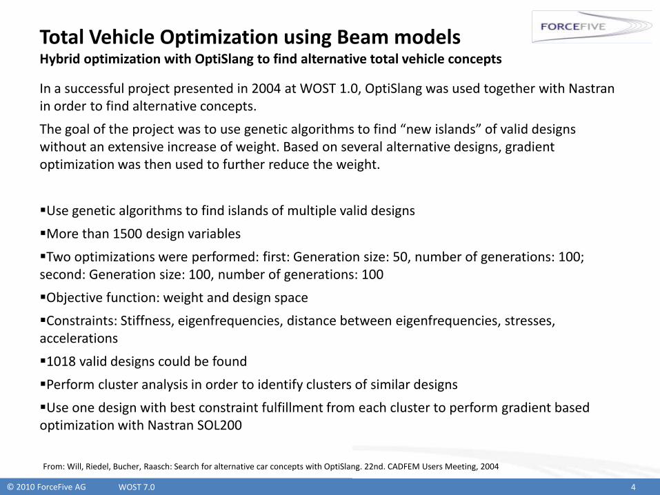
In a successful project presented in 2004 at WOST 1.0, OptiSlang was used together with Nastran in order to find alternative concepts.
The goal of the project was to use genetic algorithms to find “new islands” of valid designs without an extensive increase of weight. Based on several alternative designs, gradient optimization was then used to further reduce the weight.
Use genetic algorithms to find islands of multiple valid designs
More than 1500 design variables
Two optimizations were performed: first: Generation size: 50, number of generations: 100; second: Generation size: 100, number of generations: 100
Objective function: weight and design space
Constraints: Stiffness, eigenfrequencies, distance between eigenfrequencies, stresses, accelerations
1018 valid designs could be found
Perform cluster analysis in order to identify clusters of similar designs
Use one design with best constraint fulfillment from each cluster to perform gradient based optimization with Nastran SOL200
WOST 7.0 4
From: Will, Riedel, Bucher, Raasch: Search for alternative car concepts with OptiSlang. 22nd. CADFEM Users Meeting, 2004
© 2010 ForceFive AG
Total Vehicle Optimization using Beam modelsResults of hybrid optimization project
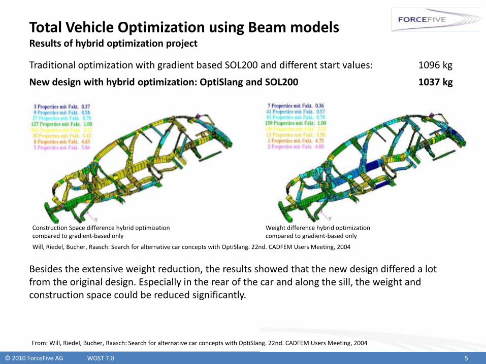
Traditional optimization with gradient based SOL200 and different start values: 1096 kg
New design with hybrid optimization: OptiSlang and SOL200 1037 kg
Besides the extensive weight reduction, the results showed that the new design differed a lot from the original design. Especially in the rear of the car and along the sill, the weight and construction space could be reduced significantly.
WOST 7.0 5
Construction Space difference hybrid optimizationcompared to gradient-based only
Weight difference hybrid optimizationcompared to gradient-based only
Will, Riedel, Bucher, Raasch: Search for alternative car concepts with OptiSlang. 22nd. CADFEM Users Meeting, 2004
From: Will, Riedel, Bucher, Raasch: Search for alternative car concepts with OptiSlang. 22nd. CADFEM Users Meeting, 2004

© 2010 ForceFive AG
Total Vehicle Optimization using Beam modelsConventional Creation of Beam Models
Despite the proven successes of optimization of beam models, the biggest drawback is the high time consumption of model creation, which has been a manual task in the past.
The following steps were required in order to convert geometry or meshes into beam models:
WOST 7.0 6
Cut through mesh Search for an equivalent standard cross section
Calculate physical properties, Shear Center
and Center of Gravity
COG (y z)SC (y, z)
Ixx, Iyy, Izz
Create beam element and property
Repeat these steps for all carrying structures
Create Shell meshes for sheet metal parts
Add rigid connections between beams and Shells
BOX
L
CHAN
Structural parts as CAD-Geometry or FE-Mesh
© 2010 ForceFive AG
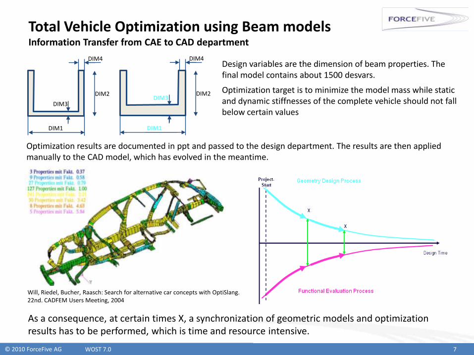
Total Vehicle Optimization using Beam modelsInformation Transfer from CAE to CAD department
WOST 7.0 7
Optimization results are documented in ppt and passed to the design department. The results are then applied manually to the CAD model, which has evolved in the meantime.
As a consequence, at certain times X, a synchronization of geometric models and optimization results has to be performed, which is time and resource intensive.
DIM1
DIM2
DIM4
DIM3
DIM1
DIM2
DIM4
DIM3
Design variables are the dimension of beam properties. The final model contains about 1500 desvars.
Optimization target is to minimize the model mass while static and dynamic stiffnesses of the complete vehicle should not fall below certain values
Will, Riedel, Bucher, Raasch: Search for alternative car concepts with OptiSlang. 22nd. CADFEM Users Meeting, 2004

© 2010 ForceFive AG
FCM: CATIA-integrated concept development
Total Vehicle Optimization using Beam models in the past
Fast Concept Modeller: CATIA-integrated concept development
Enhanced Beam Process Using Fast Concept Modeller
WOST 7.0 8

© 2010 ForceFive AG
Total Vehicle Optimization using Beam modelsGoals of FCM development
In 2007, ForceFive started the development of a software called “Fast Concept Modeller” based on BMW’s requirements.
The main goals of the project were:
WOST 7.0 9
Additional Requirements of Complete Vehicle Department:
Provide a fast way to derive Beam-Shell FE-models from CAD geometry by a rule-based beam mesher and a high degree of automization
Implement functions to apply optimization results from CAE-world to CAD-models in order to minimize synchronization efforts
Reduce usage of CAE-applications and interfaces
Implement a software for concept development that is integrated into CATIA V5
Provide interfaces to common CAE-Pre-Processors
The concept-model is the master for all CAE-processes
© 2010 ForceFive AG
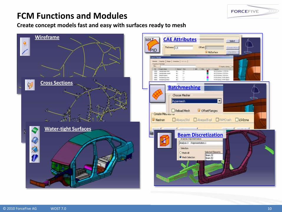
FCM Functions and ModulesCreate concept models fast and easy with surfaces ready to mesh
WOST 7.0 10
Cross Sections
Water-tight Surfaces
Wireframe CAE Attributes
Batchmeshing
Beam Discretization
© 2010 ForceFive AG
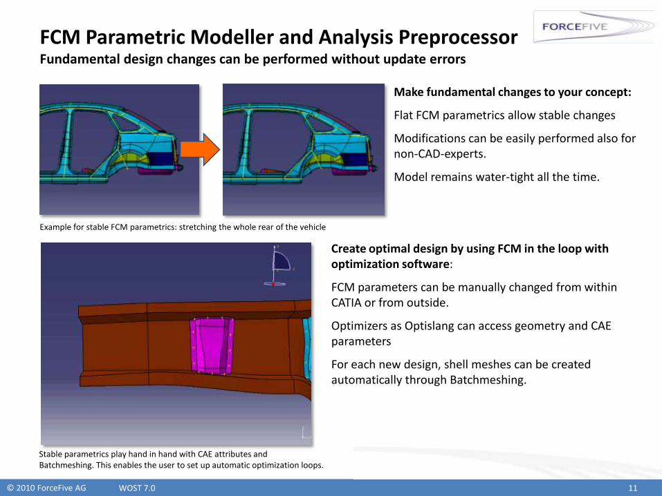
FCM Parametric Modeller and Analysis PreprocessorFundamental design changes can be performed without update errors
WOST 7.0 11
Make fundamental changes to your concept:
Flat FCM parametrics allow stable changes
Modifications can be easily performed also for non-CAD-experts.
Model remains water-tight all the time.
Create optimal design by using FCM in the loop with optimization software:
FCM parameters can be manually changed from within CATIA or from outside.
Optimizers as Optislang can access geometry and CAE parameters
For each new design, shell meshes can be created automatically through Batchmeshing.
Example for stable FCM parametrics: stretching the whole rear of the vehicle
Stable parametrics play hand in hand with CAE attributes and Batchmeshing. This enables the user to set up automatic optimization loops.
© 2010 ForceFive AG
Enhanced Beam Process Using FCM
Total Vehicle Optimization using Beam models in the past
Fast Concept Modeller: CATIA-integrated concept development
Enhanced Beam Process Using Fast Concept Modeller
WOST 7.0 12

© 2010 ForceFive AG
Creation of Nastran Beam Models with FCM Automatic conversion into Beam Models using Nastran Arbitrary Cross Sections
Fast Concept Modeller along with Nastran Arbitrary Cross Sections allows to convert the concept geometry directly into Beam Meshes.
The sections are created based on a given element length normal to the geometry and converted according to the rules of Beam Meshes. They are directly visualized in FCM and can be exported to Nastran straight away.
The meshing follows basic rules. The model topology is analyzed and accordingly converted (discretized) in a beam model.
FCM-Geometry Section of geometry (automatic)
Nastran Beam elements with ABCS properties
Shell Meshing (automatic)
Connection of Beams and Shells with RBEs (half-
automatic)
© 2010 ForceFive AG
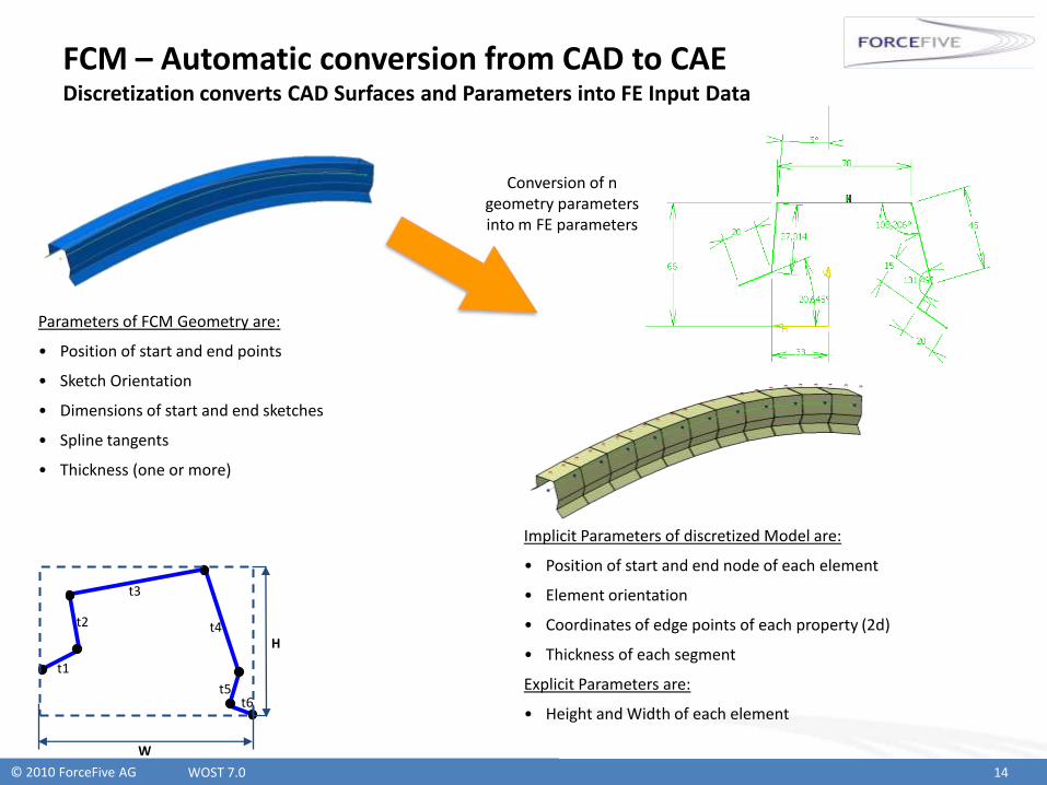
FCM – Automatic conversion from CAD to CAEDiscretization converts CAD Surfaces and Parameters into FE Input Data
WOST 7.0 14
Parameters of FCM Geometry are:
• Position of start and end points
• Sketch Orientation
• Dimensions of start and end sketches
• Spline tangents
• Thickness (one or more)
Conversion of n geometry parameters into m FE parameters
Implicit Parameters of discretized Model are:
• Position of start and end node of each element
• Element orientation
• Coordinates of edge points of each property (2d)
• Thickness of each segment
Explicit Parameters are:
• Height and Width of each element
H
W
t1
t2
t3
t4
t5t6
© 2010 ForceFive AG
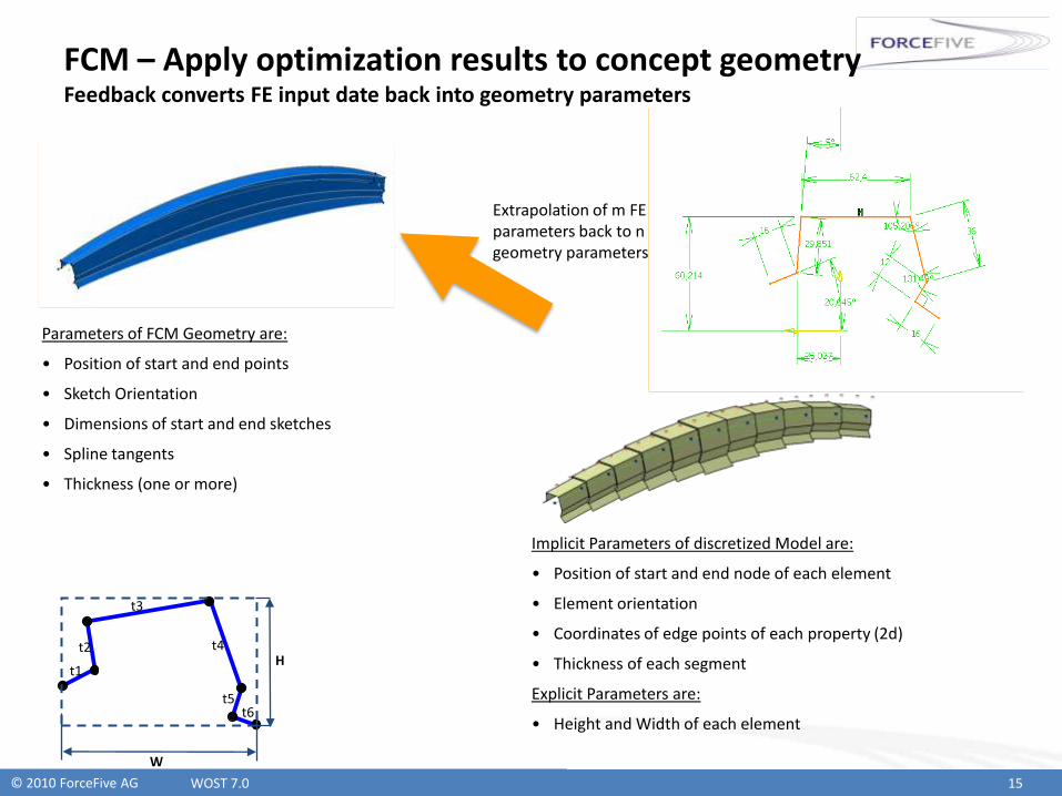
FCM – Apply optimization results to concept geometry Feedback converts FE input date back into geometry parameters
WOST 7.0 15
Parameters of FCM Geometry are:
• Position of start and end points
• Sketch Orientation
• Dimensions of start and end sketches
• Spline tangents
• Thickness (one or more)
Extrapolation of m FE parameters back to n geometry parameters
Implicit Parameters of discretized Model are:
• Position of start and end node of each element
• Element orientation
• Coordinates of edge points of each property (2d)
• Thickness of each segment
Explicit Parameters are:
• Height and Width of each element
H
W
t1
t2
t3
t4
t5t6
© 2010 ForceFive AG
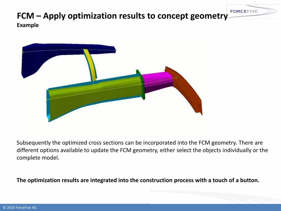
FCM – Apply optimization results to concept geometry Example
Subsequently the optimized cross sections can be incorporated into the FCM geometry. There are different options available to update the FCM geometry, either select the objects individually or the complete model.
The optimization results are integrated into the construction process with a touch of a button.
© 2010 ForceFive AG
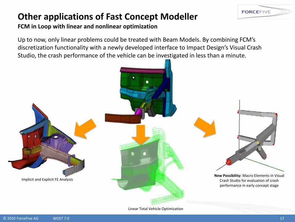
Other applications of Fast Concept Modeller FCM in Loop with linear and nonlinear optimization
Up to now, only linear problems could be treated with Beam Models. By combining FCM’s discretization functionality with a newly developed interface to Impact Design’s Visual Crash Studio, the crash performance of the vehicle can be investigated in less than a minute.
WOST 7.0 17
Implicit and Explicit FE Analysis
Linear Total Vehicle Optimization
New Possibility: Macro Elements in Visual Crash Studio for evaluation of crash performance in early concept stage

© 2010 ForceFive AG
Fast Concept Modeller for Concept Development Summary
Beam and Shell Nastran models are used in total vehicle development at BMW for optimization of full vehicle model characteristics
Hybrid optimization with optislang and Nastran SOL200 has proved to deliver much better results than using gradient based optimization solely
Based on FCM Models an automatic process to derive beam and shell models from parametric concept geometry has been realized
The feedback of optimized beam sections on initial geometry helps designers to benefit from results of the CAE-process instantaneous.
The time effort for geometric model creation and FE model derivation can be reduced by a big amount with Fast Concept Modeller. The interfaces to CAE processes deliver new possibilities for optimization of CATIA-integrated concept models.

© 2010 ForceFive AG
ForceFive AG
Hufelandstr. 7
80939 Munich
Telefon +49-89-452438-10
Telefax +49-89-452438-22
E-Mail [email protected]
Homepage www.forcefive.de
Contact:
Thomas Schmid
Telefon: +49-89-452438-10
Contact
WOST 7.0 19