OPTIMIZATION OF FAN OF INDUCTION MOTOR IN THE ANSYS … · Optimization of fan of induction motor...
7
POZNAN UNIVERSITY OF TECHNOLOGY ACADEMIC JOURNALS No 72 Electrical Engineering 2012 __________________________________________ * Brno University of Technology. Marcel JANDA* Zbynek MAKKI* Ramia DEEB* OPTIMIZATION OF FAN OF INDUCTION MOTOR IN THE ANSYS WORKBENCH This paper deals with the optimization of cooling of electric machines using Ansys Workbench. In many areas of electrical machines are increasingly used optimization methods to achieve greater performance and improved efficiency of the individual parts of electrical machines. These methods are very often connecting to computer programs such as Ansys, in order to obtain the best results. The program Ansys Workbench is several optimization algorithms that can be connected to the analysis of any group of physical fields. This allows other programs without the need to achieve optimal results in the design of electrical machines. This article specifically addresses the application of these algorithms for the adaptation of design changes the fan induction motor. Optimization was used to size the fan blades to achieve the greatest possible pressure coolant. The main dimensions of this design are limited fan induction motor and therefore are not optimized. The article discussed the results of this optimization, and also summarizes the main advantages and disadvantages of using this procedure. 1. INTRODUCTION In present time of growing need for best results, deploying the least resources. Another factor is by speeding. Very often in the optimization of parts of electrical machines connected to the algorithm being used by some FEM program. The actual optimization program is usually created in a specialized language (e.g. Matlab, Java, etc.). In contrast, computational software are equipped with basic optimization features. The ANSYS Workbench environment is a special module, which allows easy adjustment for all types, you can optimize the analysis. This gives advanced users a powerful tool, which integrates searching optimal results into a single environment for a large range of solved problems. This module can be connected to all solutions of physical field is able to solve Ansys. Optimization can solve for each analysis separately, or a combination thereof. It allows without effort and without the need for specialized staff to achieve design optimization of electric machines. Then not also need to add additional specialized software. Of course, the
Transcript of OPTIMIZATION OF FAN OF INDUCTION MOTOR IN THE ANSYS … · Optimization of fan of induction motor...

POZNAN UNIVE RSIT Y OF TE CHNOLOGY ACADE MIC JOURNALS No 72 Electrical Engineering 2012
__________________________________________ * Brno University of Technology.
Marcel JANDA* Zbynek MAKKI* Ramia DEEB*
OPTIMIZATION OF FAN OF INDUCTION MOTOR IN THE ANSYS WORKBENCH
This paper deals with the optimization of cooling of electric machines using Ansys Workbench. In many areas of electrical machines are increasingly used optimization methods to achieve greater performance and improved efficiency of the individual parts of electrical machines. These methods are very often connecting to computer programs such as Ansys, in order to obtain the best results. The program Ansys Workbench is several optimization algorithms that can be connected to the analysis of any group of physical fields. This allows other programs without the need to achieve optimal results in the design of electrical machines. This article specifically addresses the application of these algorithms for the adaptation of design changes the fan induction motor. Optimization was used to size the fan blades to achieve the greatest possible pressure coolant. The main dimensions of this design are limited fan induction motor and therefore are not optimized. The article discussed the results of this optimization, and also summarizes the main advantages and disadvantages of using this procedure.
1. INTRODUCTION
In present time of growing need for best results, deploying the least resources. Another factor is by speeding. Very often in the optimization of parts of electrical machines connected to the algorithm being used by some FEM program. The actual optimization program is usually created in a specialized language (e.g. Matlab, Java, etc.). In contrast, computational software are equipped with basic optimization features. The ANSYS Workbench environment is a special module, which allows easy adjustment for all types, you can optimize the analysis. This gives advanced users a powerful tool, which integrates searching optimal results into a single environment for a large range of solved problems. This module can be connected to all solutions of physical field is able to solve Ansys. Optimization can solve for each analysis separately, or a combination thereof. It allows without effort and without the need for specialized staff to achieve design optimization of electric machines. Then not also need to add additional specialized software. Of course, the
Marcel Janda, Zbynek Makki, Ramia Deeb
142
optimization module, which contains Ansys Workbench cannot be used in all cases. And has some limitations compared to a specialized optimization algorithms need not be the results always the best solution completely. In any case, if user A degree of error method, has available a tool will do. This allows you to save time and money.
2. OPTIMIZATION IN ANSYS WORKBENCH
Optimization in ANSYS Workbench is a maximum adjustment for fast and
easy to use. For its successful completion is necessary to do a few steps: 1) Creating a model in a CAD system and import it into ANSYS Workbench
The first necks, which is necessary for the successful optimization to do is create the model. For this purpose you can use design modeler, which is part of the ANSYS Workbench, or one of the modern CAD system. The basic condition is that the model must be created parametrically in the areas you want to optimize. In case of using external CAD system is very important save the model into a format that supports parametric models (e.g. IAM). For example, SAT format does not have this property and then import the model can’t change the dimensions and thus also conducting experiments with optimization. Importing the model itself performs in the environment de Design Modeler. Here are some possible simpler repair and eventual closure of the model into the air volume. 2) Setup of CFX analysis
The next step, which is the need to do, is setting Flow analysis in the environment ANSYS CFX. The setting is the same as in Classical Analysis. The only difference is that it is necessary to define output values, which will pass the optimization as input parameters. These values define the over expression. There it is possible to select one of the existing values, or define your own as defined optimization. 3) Setup Optimization
The last step is to set up your optimization. This is done using a special block to be added to the project scheme. In various parts of this module is then set, which will change the parameters and to what extent the change occurs. Dale here defines the output parameters, which are the result of each analysis (in this case, analysis of flow). After you run the basic computation is performed sensitivity analysis on model parameters individually. Makes it possible to find parameter with largest impact on the output variable and eventually readjust accordingly optimization algorithm.

Optimization of fan of induction motor in the Ansys Workbench
143
Fig. 1. Project schematic of optimization in Ansys Workbench
3. OPTIMIZATION OF FAN OF INDUCTION MACHINE
Figure 1 shows the fan model created in Autodesk Inventor. It is a simple type of fan that is used in electrical machines. Overall, it was defined by nine parameters that affect the construction of the fan. All parameters were marked prefix “DS”, which is necessary to successfully import the parametric model. This prefix can be arbitrary, but the need for importing set mainstreaming.
Fig. 2. Fan model
Table 1 lists the parameters and their significance in the model. All variables were defined, in millimeters, and this unit was also set as the basic model when importing into Ansys Workbench environment. For the actual optimization were applied to all parameters. Some dimensions had to be maintained due to the size of electrical machines and meet specifications.
Marcel Janda, Zbynek Makki, Ramia Deeb
144
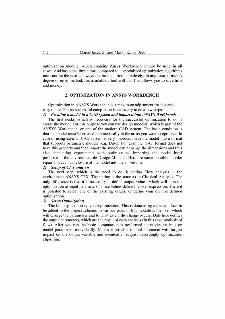
Table 1. Parameters of fan model
PARAMETER P1 shaft diameter Input parameter mm P2 fan height Input parameter mm P3 radius of the lower part of the fan Input parameter mm P4 fan base height Input parameter mm P5 chamfer blade Input parameter mm P6 blade length Input parameter mm P7 height of blades Input parameter mm P8 number of blades Input parameter - P9 fan flow rate Output parameter 1. sm
4. OPTIMIZATION SENSITIVITY
During the optimization is performed sensitivity analysis. The user can
visualize the sensitivity of the output parameters of input parameters. There are a number of graphic displays, allowing the user to evaluate the influence of individual parameters.
Fig. 3. Optimization sensitivity on number of blades
Fig. 4. Optimization sensitivity on height
of blades
Figure 3 is seen to affect the number of blades pass the air velocity in the neighborhood of the fan. Although the difference in whether a graphical view that matter is not so striking. The value of air velocity is changing only in the range of 0.1 m / s. Figure 4 is seen depending on the height blades. As you can see the value of air velocity depended not only to an altitude of blades a certain value. He already does not have a change of this parameter has no effect. This makes it possible to adjust to changes in other optimization parameter at a constant height
Optimization of fan of induction motor in the Ansys Workbench
145
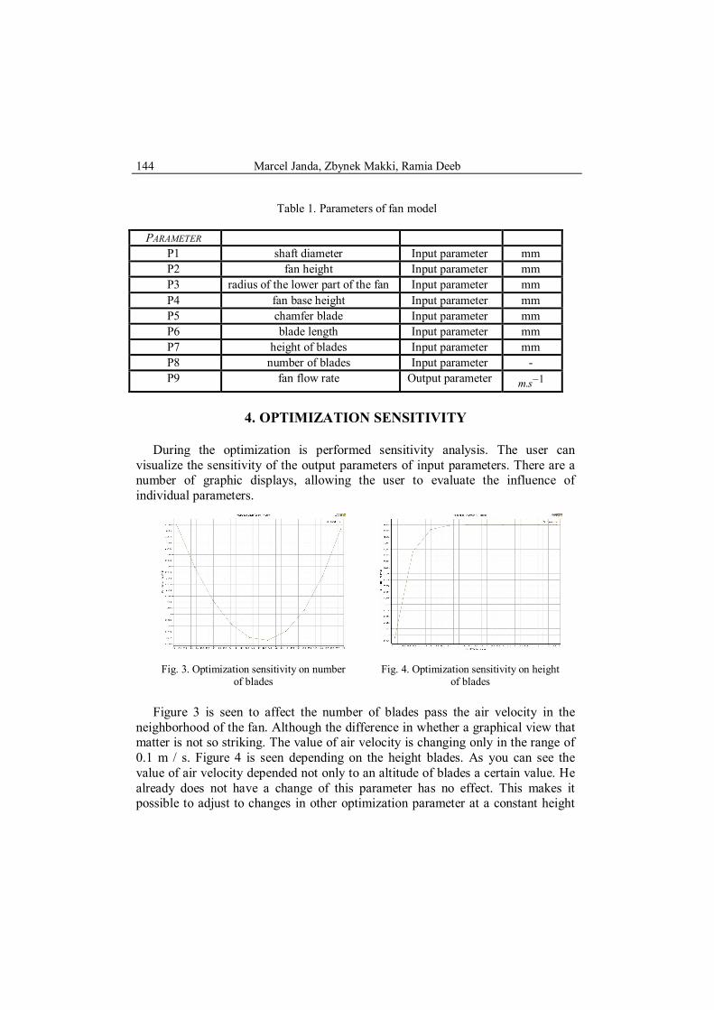
blades. This simplifies other possible calculations. In Figure 5 is a 3-dimensional sensitivity portrayed an output parameter on the number of blade fan.
Fig. 5. Optimization sensitivity on number of blades and blade chamfer
5. RESULTS OF OPTIMIZATION
The optimization algorithm is calculated the range of outcomes, which are then
evaluated. Table 2 shows the best results, which were substituted in the calculation. For each parameter is specified as a condition set for optimum performance. These conditions were set at the request of the submitter.
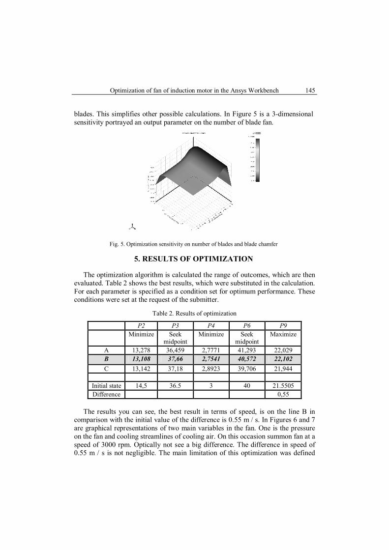
Table 2. Results of optimization
P2 P3 P4 P6 P9 Minimize Seek
midpoint Minimize Seek
midpoint Maximize
A 13,278 36,459 2,7771 41,293 22,029 B 13,108 37,66 2,7541 40,572 22,102 C 13,142 37,18 2,8923 39,706 21,944
Initial state 14,5 36.5 3 40 21.5505 Difference 0,55
The results you can see, the best result in terms of speed, is on the line B in
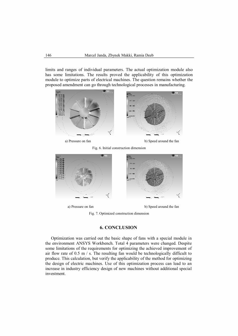
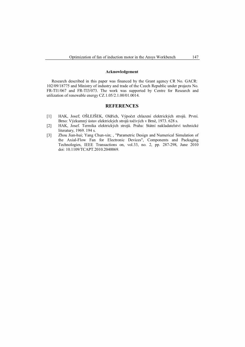
comparison with the initial value of the difference is 0.55 m / s. In Figures 6 and 7 are graphical representations of two main variables in the fan. One is the pressure on the fan and cooling streamlines of cooling air. On this occasion summon fan at a speed of 3000 rpm. Optically not see a big difference. The difference in speed of 0.55 m / s is not negligible. The main limitation of this optimization was defined
Marcel Janda, Zbynek Makki, Ramia Deeb
146
limits and ranges of individual parameters. The actual optimization module also has some limitations. The results proved the applicability of this optimization module to optimize parts of electrical machines. The question remains whether the proposed amendment can go through technological processes in manufacturing.
a) Pressure on fan b) Speed around the fan
Fig. 6. Initial construction dimension
a) Pressure on fan b) Speed around the fan
Fig. 7. Optimized construction dimension
6. CONCLUSION
Optimization was carried out the basic shape of fans with a special module in the environment ANSYS Workbench. Total 4 parameters were changed. Despite some limitations of the requirements for optimizing the achieved improvement of air flow rate of 0.5 m / s. The resulting fan would be technologically difficult to produce. This calculation, but verify the applicability of the method for optimizing the design of electric machines. Use of this optimization process can lead to an increase in industry efficiency design of new machines without additional special investment.
Optimization of fan of induction motor in the Ansys Workbench
147
Acknowledgement
Research described in this paper was financed by the Grant agency CR No. GACR: 102/09/18775 and Ministry of industry and trade of the Czech Republic under projects No. FR-TI1/067 and FR-TI3/073. The work was supported by Centre for Research and utilization of renewable energy CZ.1.05/2.1.00/01.0014.
REFERENCES
[1] HAK, Josef; OŠLEJŠEK, Oldřich, Výpočet chlazení elektrických strojů. První.
Brno: Výzkumný ústav elektrických strojů točivých v Brně, 1973. 628 s. [2] HAK, Josef. Termika elektrických strojů. Praha: Státní nakladatelství technické
literatury, 1969. 194 s. [3] Zhou Jian-hui; Yang Chun-xin; , "Parametric Design and Numerical Simulation of
the Axial-Flow Fan for Electronic Devices", Components and Packaging Technologies, IEEE Transactions on, vol.33, no. 2, pp. 287-298, June 2010 doi: 10.1109/TCAPT.2010.2040069.