Optimisation of Superalloy heat...
24
Optimisation of single crystal superalloy homogenisation heat treatment using DICTRA and MICRESS simulations N. Warnken * , H. Larsson + , R. Reed * * University of Birmingham + KTH Stockholm
Transcript of Optimisation of Superalloy heat...

Optimisation of single crystal superalloy
homogenisation heat treatment
using DICTRA and MICRESS simulationsN. Warnken*, H. Larsson+, R. Reed*
* University of Birmingham
+ KTH Stockholm
Outline
• Bridgman processing of superalloys, overview
• Models
• Results on solidification and homogenisation
• Approach for the optimisation
• Outlook

Directional solidification of superalloys
The directional heat flux forces the crystals to grow in a given direction
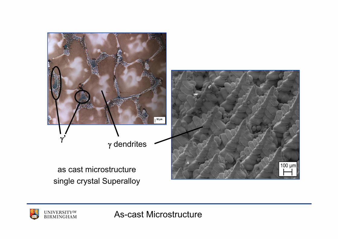
As-cast Microstructure
as cast microstructure
single crystal Superalloy
γγγγ dendritesγγγγ’

Microstructure evolution during processing
Aged
CMSX4
As-cast
Homogenised
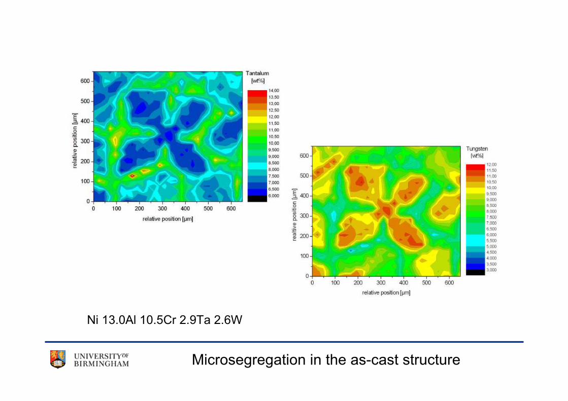
Microsegregation in the as-cast structure
Ni 13.0Al 10.5Cr 2.9Ta 2.6W
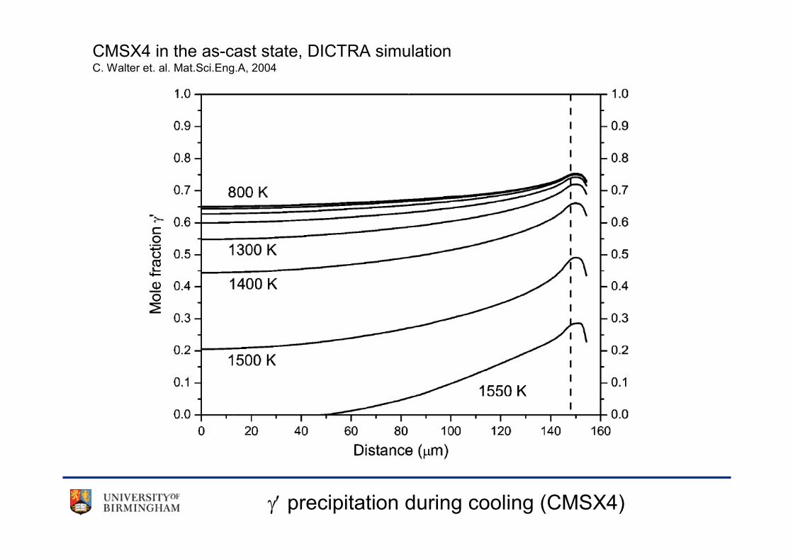
γ′ precipitation during cooling (CMSX4)
CMSX4 in the as-cast state, DICTRA simulationC. Walter et. al. Mat.Sci.Eng.A, 2004
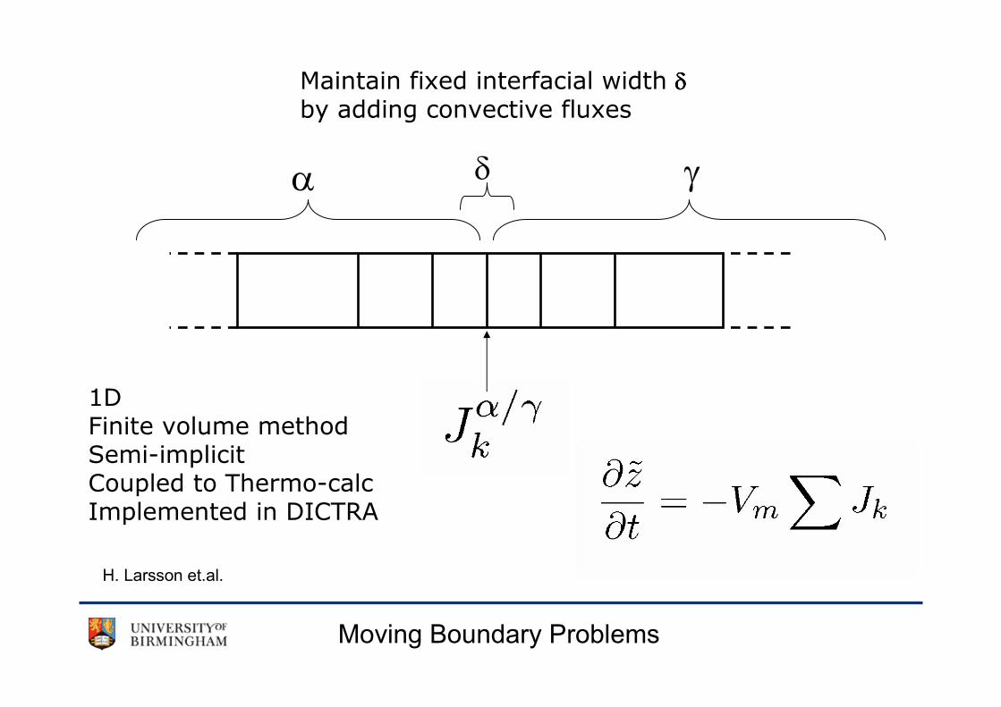
Moving Boundary Problems
α γ
Maintain fixed interfacial width δδδδby adding convective fluxes
δ
1DFinite volume methodSemi-implicitCoupled to Thermo-calcImplemented in DICTRA
H. Larsson et.al.

• Diffuse Interface, expressed by the Phase-field Parameter φ:φ:φ:φ:
• Introduction of an orderparameter φ = f (x,t), which is a density function
for the phase distribution.
Phase Field Approach
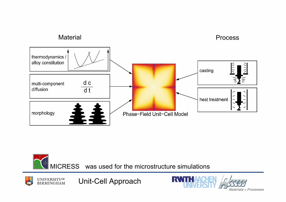
MICRESS was used for the microstructure simulations
Material Process
Unit-Cell Approach
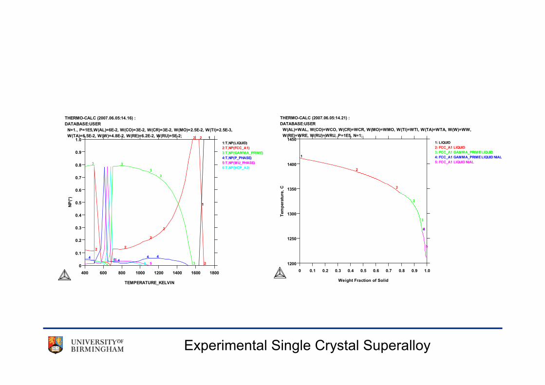
Experimental Single Crystal Superalloy
0
0.1
0.2
0.3
0.4
0.5
0.6
0.7
0.8
0.9
1.0
NP
(*)
400 600 800 1000 1200 1400 1600 1800
TEMPERATURE_KELVIN
THERMO-CALC (2007.06.05:14.16) :
DATABASE:USER
N=1., P=1E5,W(AL)=6E-2, W(CO)=3E-2, W(CR)=3E-2, W(MO)=2.5E-2, W(TI)=2.5E-3,
W(TA)=6.5E-2, W(W)=4.8E-2, W(RE)=6.2E-2, W(RU)=5E-2;1
1:T,NP(LIQUID)
2
2:T,NP(FCC_A1)
1
22
3
3:T,NP(GAMMA_PRIME)
2
3
4
4:T,NP(P_PHASE)
2
3
5
5:T,NP(MU_PHASE)
4
2
3
6
6:T,NP(HCP_A3)
5 4
2
3
654
1200
1250
1300
1350
1400
1450
Tem
pera
ture
, C
0 0.1 0.2 0.3 0.4 0.5 0.6 0.7 0.8 0.9 1.0
Weight Fraction of Solid
THERMO-CALC (2007.06.05:14.21) :
DATABASE:USER
W(AL)=WAL, W(CO)=WCO, W(CR)=WCR, W(MO)=WMO, W(TI)=WTI, W(TA)=WTA, W(W)=WW,
W(RE)=WRE, W(RU)=WRU, P=1E5, N=1;
1
1: LIQUID
2
2: FCC_A1 LIQUID
2
3
3: FCC_A1 GAMMA_PRIME LIQUID
3
4
4: FCC_A1 GAMMA_PRIME LIQUID NIAL
5
5: FCC_A1 LIQUID NIAL
5

Results of the 1D model
Dashed – as-cast profileSolid – after 40000 s (~10 h)
Al Re
LDSX6
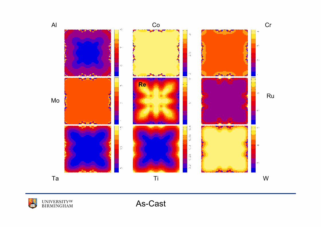
As-Cast
Al Co Cr
MoRu
Ta Ti W
Re
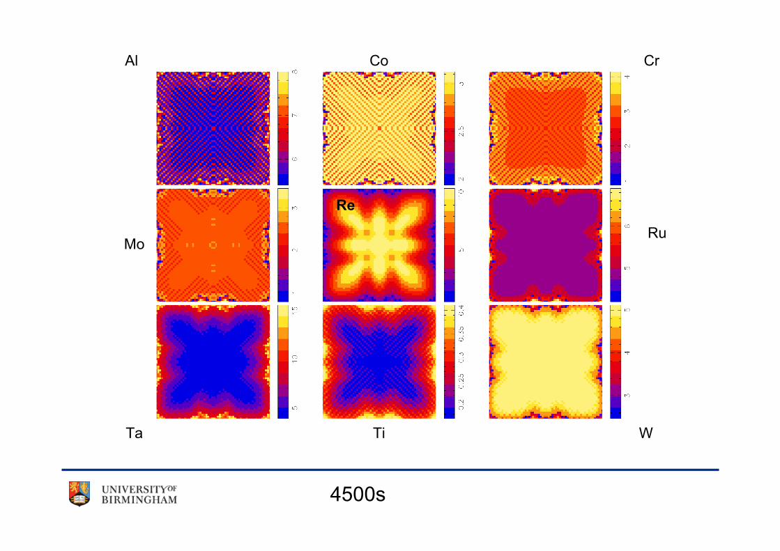
4500s
Al Co Cr
MoRu
Ta Ti W
Re

8375s
Al Co Cr
MoRu
Ta Ti W
Re

13743s
Al Co Cr
MoRu
Ta Ti W
Re

20343s
Al Co Cr
MoRu
Ta Ti W
Re

23943s
Al Co Cr
MoRu
Ta Ti W
Re

26643s
Al Co Cr
MoRu
Ta Ti W
Re
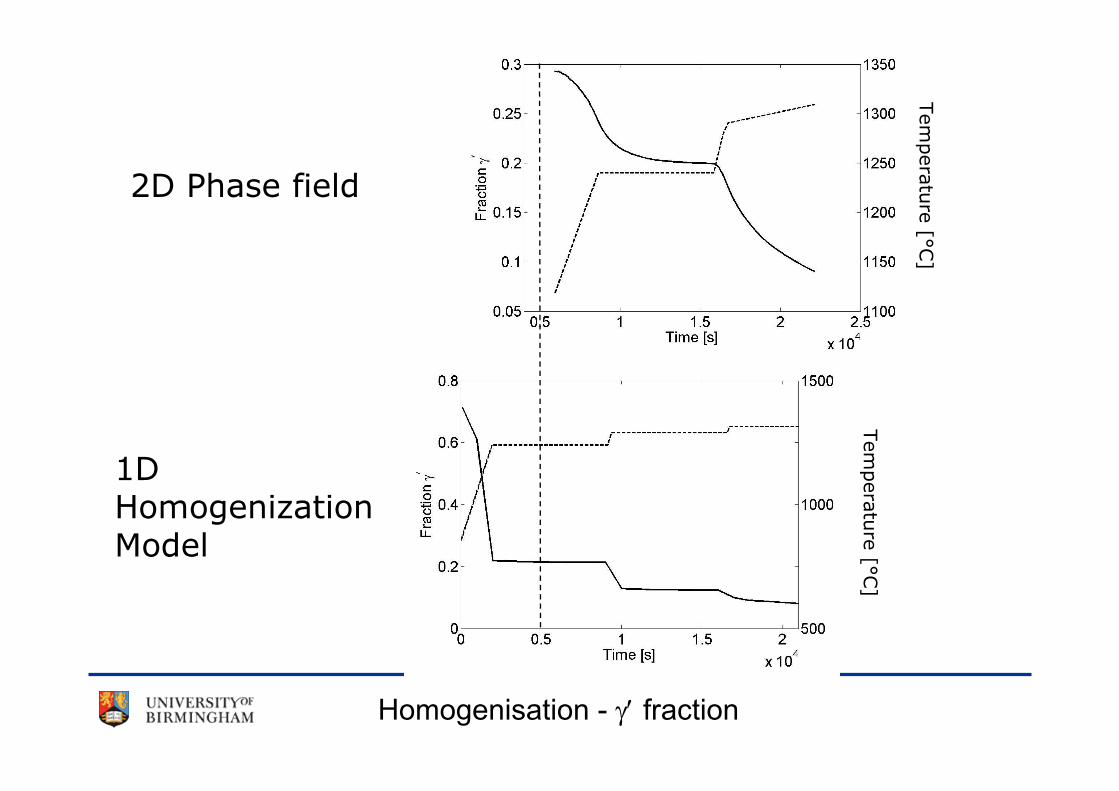
Homogenisation - γ′ fraction
2D Phase field
1D HomogenizationModel
Tem
pera
ture
[°C]
Tem
pera
ture
[°C]

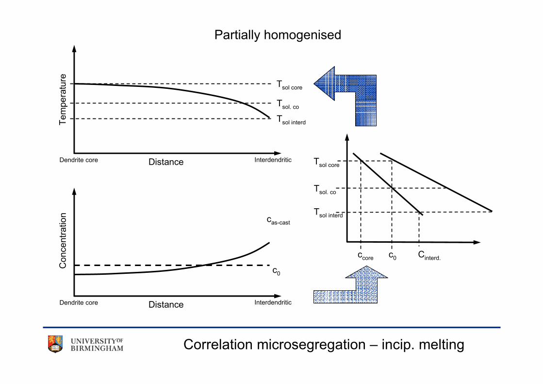
Correlation microsegregation – incip. melting
Dendrite core Interdendritic
Concentration
Temperature
c0
cas-cast
Distance
Dendrite core InterdendriticDistance
c0
Tsol. co
Tsol core
Tsol interd
Cinterd.ccore
Tsol. co
Tsol core
Tsol interd
As-Cast
Correlation microsegregation – incip. melting
Dendrite core Interdendritic
Concentration
Temperature
c0
cas-cast
Distance
Dendrite core InterdendriticDistance
c0
Tsol. co
Tsol core
Tsol interd
Cinterd.ccore
Tsol. co
Tsol core
Tsol interd
Partially homogenised

Simulation of ”Optimised” homogenisation
• Target temperature Ttarget =Tsol(t)-10 [K]
• Maximum heating/cooling rate 4 K/min
• Input from simulation of solidification

Future Work
• Derivation of an optimised solution heat treatment
• Nucleation of γ′
• Including other phases in the simulation (i.e. NiAl)
• Influence of primary spacing on homogenisation
• Cross check with other simulations / experiments
• Alloy variation
• Speed up simulations