Optimisation of Binaural Room Scanning (BRS): … Conf.pdf · Optimisation of Binaural Room...
12
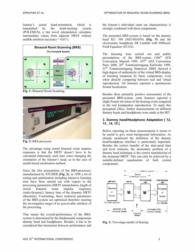
Optimisation of Binaural Room Scanning (BRS): Considering inter-individual HRTF-characteristics Gerhard Spikofski, Markus Fruhmann, Institut für Rundfunktechnik GmbH, Munich The headphone-based Binaural Room Scanning (BRS) auralisation system relies on real-measured binaural room responses by means of a dummy head. Convoluting the measured binaural room responses with the input signals by means of the BRS Processor and reproducing the resulting signals by headphones, a virtual representation of the scanned room situation is achieved. Taking into account spontaneous head movements by means of head-tracking typical dummy head, artefacts like front/back inversions are efficiently suppressed. The main applications of the BRS-system are the virtual representation of stereo or multi-channel control rooms to realise optimal virtual conditions in real inadequate conditions. In the evaluation experiments during the development phase of the system, artefacts from the processing caused by necessary simplifications could be eliminated. Thus the quality of the system preliminary depends on human cues, that means individual HRTF regarding room scanning as well as headphone reproduction. An optimisation of the BRS system with specific respect to the inter-individual HRTF differences is investigated. 1. Principle of Binaural Room Scanning (BRS) The BRS-system is based on scanning and virtual display of real listening situations by means of a dummy head, that is the corresponding binaural Head Related Transfer Functions (HRTF). The signals to be synthesised, e. g. virtual sound signals reproduced by a single loudspeaker of the listening set-up, are processed by convoluting the input signal with the corresponding HRTF. The output signals which are processed for headphone reproduction should be identical with dummy head signals recorded at the listening position of the listening environment. That means the BRS-processor in principle is a dummy head and thus the basic results from dummy head investigations are valid [ 1, 2, 3, 4, 5, 6, 7 ]. Among others, one important result of the corresponding investigations is a suitably-defined interface dummy head/headphone transfer function. In the case of BRS, the reference interface is defined by a frequency independent diffused sound field transfer function. Only if the dummy head as well as the headphones refer to the defined interface characteristics, the HRTF are transmitted correctly. In order to meet this requirement, both dummy head and BRS-processor should generate sound perception equal to the original sound field. However, with this static scanning of the listening situation, the typical dummy head front/rear inversions occur. To eliminate this disturbing perception feature, we have incorporated head movement. The head movement is realised by means of a head-tracking system which transmits the listener’s head movements to the BRS processor. For dynamic allocation of the HRTF corresponding to the listener’s head movements the data-store of the BRS processor doesn’t only contain the scanned-in HRTF of the corresponding standard directions but additionally the frontal horizontal plane over the range of ± 42°. By means of dynamic HRTF allocation as a function of the listener’s head movements, front/rear inversions can be effectively avoided (see 4. ). 2. Realisation of BRS [ 8, 9, 10, 11 ] In contrast to model-based auralisation systems, the data-based BRS-system enables virtual “cloning” of the acoustics of existent listening situations with reduced processing capacity compared to model- based systems. The auralisation is basically done in two steps: Measurement of the acoustical room/loudspeaker data and actual auralisation (Fig. 1). Step 1: Considering stereo or multi-channel 5 +1 listening, the binaural room impulse responses of each loudspeaker have to be measured at first. In order to realise dynamic HRTF allocation by head- tracking, the HRTF of the frontal horizontal plane over the range of ± 42º (resolution = 6º) have to be measured for each loudspeaker additionally. The result of these measurements is the data-base of the BRS-processor which captures all relevant acoustical characteristics of the listening situation at the listening position. Step 2: In the second step the headphone signals are processed in real-time. The processing includes convolution of the input signals with the respective binaural room impulse responses and - with respect to the dynamic HRTF allocation - interpolation of the HRTF of the frontal plane. Depending on the
-
Upload
phungkhanh -
Category
Documents
-
view
215 -
download
0
Transcript of Optimisation of Binaural Room Scanning (BRS): … Conf.pdf · Optimisation of Binaural Room...

Optimisation of Binaural Room Scanning (BRS): Considering inter-individual HRTF-characteristics
Gerhard Spikofski, Markus Fruhmann, Institut für Rundfunktechnik GmbH, Munich
The headphone-based Binaural Room Scanning (BRS) auralisation system relies on real-measured binaural room responses by means of a dummy head. Convoluting the measured binaural room responses with the input signals by means of the BRS Processor and reproducing the resulting signals by headphones, a virtual representation of the scanned room situation is achieved. Taking into account spontaneous head movements by means of head-tracking typical dummy head, artefacts like front/back inversions are efficiently suppressed. The main applications of the BRS-system are the virtual representation of stereo or multi-channel control rooms to realise optimal virtual conditions in real inadequate conditions. In the evaluation experiments during the development phase of the system, artefacts from the processing caused by necessary simplifications could be eliminated. Thus the quality of the system preliminary depends on human cues, that means individual HRTF regarding room scanning as well as headphone reproduction. An optimisation of the BRS system with specific respect to the inter-individual HRTF differences is investigated. 1. Principle of Binaural Room Scanning (BRS) The BRS-system is based on scanning and virtual display of real listening situations by means of a dummy head, that is the corresponding binaural Head Related Transfer Functions (HRTF). The signals to be synthesised, e. g. virtual sound signals reproduced by a single loudspeaker of the listening set-up, are processed by convoluting the input signal with the corresponding HRTF. The output signals which are processed for headphone reproduction should be identical with dummy head signals recorded at the listening position of the listening environment. That means the BRS-processor in principle is a dummy head and thus the basic results from dummy head investigations are valid [ 1, 2, 3, 4, 5, 6, 7 ]. Among others, one important result of the corresponding investigations is a suitably-defined interface dummy head/headphone transfer function. In the case of BRS, the reference interface is defined by a frequency independent diffused sound field transfer function. Only if the dummy head as well as the headphones refer to the defined interface characteristics, the HRTF are transmitted correctly. In order to meet this requirement, both dummy head and BRS-processor should generate sound perception equal to the original sound field. However, with this static scanning of the listening situation, the typical dummy head front/rear inversions occur. To eliminate this disturbing perception feature, we have incorporated head movement. The head movement is realised by means of a head-tracking system which transmits the listener’s head movements to the BRS processor. For dynamic allocation of the HRTF corresponding to the listener’s head movements the data-store of the BRS
processor doesn’t only contain the scanned-in HRTF of the corresponding standard directions but additionally the frontal horizontal plane over the range of ± 42°. By means of dynamic HRTF allocation as a function of the listener’s head movements, front/rear inversions can be effectively avoided (see 4. ). 2. Realisation of BRS [ 8, 9, 10, 11 ] In contrast to model-based auralisation systems, the data-based BRS-system enables virtual “cloning” of the acoustics of existent listening situations with reduced processing capacity compared to model-based systems. The auralisation is basically done in two steps: Measurement of the acoustical room/loudspeaker data and actual auralisation (Fig. 1). Step 1: Considering stereo or multi-channel 5+1 listening, the binaural room impulse responses of each loudspeaker have to be measured at first. In order to realise dynamic HRTF allocation by head-tracking, the HRTF of the frontal horizontal plane over the range of ± 42º (resolution = 6º) have to be measured for each loudspeaker additionally. The result of these measurements is the data-base of the BRS-processor which captures all relevant acoustical characteristics of the listening situation at the listening position. Step 2: In the second step the headphone signals are processed in real-time. The processing includes convolution of the input signals with the respective binaural room impulse responses and - with respect to the dynamic HRTF allocation - interpolation of the HRTF of the frontal plane. Depending on the
SPIKOFSKI ET AL. OPTIMISATION OF BINAURAL ROOM SCANNING (BRS)
listener’s actual head-orientation, which is transmitted by the head-tracking system (POLEMUS), a fast novel interpolation calculates intermediate values from adjacent HRTF without audible artefacts (accuracy = 0.01°).
V i r t u a l L i s t e n i n g R
o o m
Head Tracker
BRS -
Processor
3/2-Stereo Mix
R e a l
L i s t e n i n g R o o m
Binaural Room Scanning (BRS)The Complete System
Dummy Head Listener
Fig. 1: Binaural Room Scanning
Fig. 2: BRS-processor The advantage using stored binaural room impulse responses is that the HRTF doesn’t have to be calculated elaborately each time when changing the orientation of the listener’s head, as in the case of model-based auralisation method. Since the first presentation of the BRS-processor, manufactured by STUDER (Fig. 2), in 1998 a lot of testing and optimisation including intensive listening tests have been carried out with respect to the processing parameters (HRTF interpolation, length of stored binaural room impulse responses (static/dynamic), latency time of the dynamic HRTF allocation). Concluding, these technical parameters of the BRS-system are optimised therefore meeting the investigation target of no perceivable artefacts of the processing. That means the overall-performance of the BRS-system is determined by the fundamental components dummy head and headphones. Besides, it has to be considered that interaction between performance and
the listener’s individual outer ear characteristics is strongly combined with these components. The presented BRS-system is based on the dummy head KU 100 (NEUMANN) (Fig. 5) and the electrostatic headphone SR Lambda with Diffused-Field Equaliser (STAX). The listening tests carried out and public presentations of the BRS-system (106th AES Convention Munich 1999, 107th AES Convention Paris 2000, 20th Tonmeistertagung Karlsruhe 1998, 21th Tonmeistertagung Hannover 2000) showed a high degree of authenticity of the virtual BRS-display of listening situations by these components, even when directly comparing between real and virtual reproduction. All listeners reported a spontaneous frontal localisation. Besides these primarily positive assessments of the presented BRS-system, some listeners reported a slight frontal elevation of the hearing event compared to the real loudspeaker reproduction. To study this perceptual effect, further measurements on different dummy heads and headphones were made at the IRT. 3. Dummy head/Headphone Adaptation [ 12, 13 , 14, 15 ] Before reporting on these measurements it seems to be useful to give some background information. As already mentioned the definition of the dummy head/headphone interface is particularly important. Besides the correct transfer of the inter-aural time and level relations, the elementary problem of a dummy head technique is the correct reproduction of the monaural HRTF. This can only be achieved by a suitable-defined equalisation of both system components.
Fig. 3: Two-stage-model of hearing
AES 19TH INTERNATIONAL CONFERENCE 2

SPIKOFSKI ET AL. OPTIMISATION OF BINAURAL ROOM SCANNING (BRS)
The answer to this problem is given by the model of hearing presented by THEILE [ 12 ]. Following this model the hearing principally works based on associative pattern recognition (Fig. 3). In detail the hearing process works two-dimensionally. In the first stage (location determining stage), the outer ear filtering depending on direction and distance of the sound source is decoded as sound source location. In the second stage (gestalt determining stage), other characteristics of the sound source like timbre are decoded. Additionally, regarding the compatibility requirements – besides dummy head/headphones reproduction of dummy head signals via loudspeakers as well as stereo signals via headphones – not a single direction related but direction independent adaptation of the interface dummy head/headphone guaranties a correct transfer of the HRTF. Technically expressed this requirement means a frequency independent diffused field transfer function of the dummy head as well as the headphones. Based upon the above described principles the constructive features of the dummy head are determined. The dummy head should be a replica of the human head including pinna, whereas abstracted forms are permissible if meeting the natural proportions. With respect to the shape and the importance of the pinna, the manufactures mostly do an imprint of a human pinna. As there are great inter-individual differences resulting in different HRTF, a sufficient number of measurements on human subjects have to be carried out and corresponding averaging has to be done to select a suitable dummy head pinna. To complete the dummy head microphone, high quality studio-microphones have to be integrated realising sound scanning about 3 mm behind the entrance of the ear-canal. The measurements in the diffused field allow us to adjust the filter-parameters (electrical/acoustical) to realise a frequency independent diffused field transfer function meeting the defined interface. To realise headphone adaptation to the diffused-field equalised dummy head, the headphones have to be measured and accordingly equalised. Regarding headphones that means, the headphone has to replace the outer ear function in the diffused field, because putting on the headphones the outer ear of the subject becomes ineffective. Because of the inter-individual outer ear differences a sufficient number of subjects have to be measured. As no artificial ear coupler is known meeting this requirements, the measurements
have to be done on subjects in the diffused field. Principally the measurements could be related to loudness or sound level. Our measurements refer to [ 15 ] which recommends a sound-level comparison by means of a probe microphone.
Fig. 4: Measurement of individual headphone transfer function The measurements are principally carried out by fixing a probe microphone in the ear-canal of the subject measuring the sound level under loudspeaker and headphone reproduction in the diffused field one by one (Fig. 4). The measurements are done in third octave bands. The difference between loudspeaker and headphone reproduction is calculated in each third octave band resulting in the individual diffused field transfer function. Referring to [ 15 ] the measurements have to be carried out on 16 subjects calculating the average value. A diffused field equalisation is realised by means of the inverse transfer function as a filter-curve. 3.1 Dummy head Adjustment The dummy heads measured in the presented study are well-known from acoustical and psycho-acoustic research. The dummy head systems listed below (in the following anonymously indicated as K1 – K7) are investigated in detail (Fig. 5).
- HMS III [HEAD acoustics] - HUGO [Institut Technische Akustik,
Rheinisch-Westfälische Technische Hochschule Aachen]
- MANIKIN MK1 [Neutrik-Cortex Instruments]
- KU 81 [Neumann]
AES 19TH INTERNATIONAL CONFERENCE 3

SPIKOFSKI ET AL. OPTIMISATION OF BINAURAL ROOM SCANNING (BRS)
- KU 100 [Neumann]
-10
0
10
20
30
40
50
60
70
100
125
160
200
250
315
400
500
630
800
1000
1250
1600
2000
2500
3150
4000
5000
6300
8000
1000
0
1250
0
1600
0
fm ( 3rd octave ) / Hz
Diff
used
fiel
d tr
ansf
er fu
nctio
n / d
B
- KU 100 [Neumann] with torso of MK 1 [Cortex-Neutrik Instruments]
- KEMAR [Knowles Electronics Manikin for Acoustic Research] [ 16 ]
Fig. 5: Investigated dummy head systems The measured diffused field transfer function of the dummy heads are shown in Fig. 6. The corresponding inverse functions are the transfer function target achieving the diffused field equalisation, that is the correct HRTF in each case. The digital equalisation was realised by means of BRS-processing.
Fig. 6: Dummy head diffused field transfer functions
-10
0
10
20
30
40
50
60
70
100
125
160
200
250
315
400
500
630
800
1000
1250
1600
2000
2500
3150
4000
5000
6300
8000
1000
0
1250
0
1600
0
fm ( 3rd octave ) / Hz
Dire
ctiv
ity in
dex
/ dB
Fig. 7: Directivity indices of dummy heads and subjects Additionally, the directivity indices, that is the diffused field related free-field transfer function (0°, in front) are presented in Fig. 7 The directivity index represents an important frontal localisation cue of the median plane. On the other hand, probe measurements on subjects are qualified to carry out such relative measurements and thus compare human and dummy head directivity indices. 3.2 Headphone Adjustment Because the IRT-measurements of the diffused-field transfer function of the standard BRS-headphone SR Lambda with Diffused Field Equaliser (STAX), defining the equalisation target of the available equaliser device were already done in 1988, [ 14 ] and in order to show that the BRS-system does not work headphone dependent, new measurements on the SR Lambda and two other well selected high quality dynamic headphones were carried out as described above (HD 600 (SENNHEISER), DT 831 (BEYER)).
AES 19TH INTERNATIONAL CONFERENCE 4

SPIKOFSKI ET AL. OPTIMISATION OF BINAURAL ROOM SCANNING (BRS)
Fig 8. show the average values and 95%-confidence intervals of the probe diffused field transfer functions of the measured headphones (anonymously indicated as H 1- H 3), including the tolerance field recommended by [ 15 ]. In the case of exceeding the tolerances the inverse curves of the diffused field transfer functions are the equalisation target guaranteeing the required frequency independent diffused field transfer function. The digital equalisation is realised by BRS-processing again.
Fig. 8: Headphone diffused field transfer functions 4. Performance of Dummy head-System with Head-Tracking – Horizontal Localisation [ 9, 17 ] In order to investigate the impact of head rotation on binaural localisation in the horizontal plane by head-tracking - with particular respect to front/back inversions - corresponding experiments were performed at the IRT. The basic experimental set-up consists of the following elements. dummy head/headphone-system (KU 100 (NEUMANN), SR Lambda with Diffused-Field Equaliser (STAX)), whereas the dummy head is mounted on a step-motor driven turntable (Fig. 9). The rotation control of the dummy head/motor unit is achieved by head-tracking. The sensor unit of the head-tracking system mounted at the headphone transmits the rotational component of head movements of the listener to the dummy head/motor device following the rotation of the listener’s head synchronously. The listening set-up, 5+1 multi-channel loudspeaker arrangement at the IRT studio meets the international requirements on professional listening situation [ 18, 19, 20 ]. The listening test was divided in three parts: 1) Localisation with fixed dummy head.
2) Localisation with movable dummy head by head tracking. 3) Localisation with own ears.
-10
-5
0
5
10
15
20
25
30
100
125
160
200
250
315
400
500
630
800
1000
1250
1600
2000
2500
3150
4000
5000
6300
8000
1000
0
1250
0
1600
0
fm (3rd octave)
Diff
used
Fie
ld T
rans
fer F
unct
ion
/ dB
Fig. 9: Dummy head/turntable-unit In the first two experiments, the dummy head was placed at the optimal listening position at the IRT listening room, whereas the listeners were placed in quiet chamber nearby. In the third experiment – localisation with own ears – the corresponding listener was placed in the listening room at the dummy head position. As a test signal, a recording of male speech was used. Besides direct sound sources reproduced by a single loudspeaker, phantom sources were also investigated, produced by a pair of vicinal loudspeakers with the following level relation (2:1 = semi left, 1:1 = middle, 1:2 = semi right. All together 30 sound stimuli were presented including a sufficient number of stimuli for cross-checking (Fig. 10). After being introduced by a training session, the 18 subjects were asked to determine the apparent position of the presented stimulus. The results of the localisation experiments are presented in Fig. 11-13. Whereas the abscissa denotes the azimuth, the ordinate denotes the perceived azimuth of the presented sound sources. For orientating purposes, the positions of the
AES 19TH INTERNATIONAL CONFERENCE 5

SPIKOFSKI ET AL. OPTIMISATION OF BINAURAL ROOM SCANNING (BRS)
loudspeakers L, R, C, LS1, LS2, RS1, RS2 are marked as vertical lines. Additionally prominent phantom sources are characterised by vertical dashed lines. Ideally, that is when localising correctly the assessments result in a linear relation given by a diagonal line between the direction of sound and hearing event .
30°
70°
250°
290°
330°
0°
(real) sound source
listener ordummy head
RS1
RC
L
LS1
LS2 RS2
3m
110°
phantom source
Fig. 10: Tested directions By comparing the results of the two experiments “movable dummy head” and “own ears” (Fig. 12, 13) it can be recognised that there is no significant difference between the localisation curves. This corresponds to the linearity as well as the variation of the results. The presented results show that the head movement parameter, particularly head rotation in the horizontal plane realised by head-tracking, can efficiently eliminate front/back inversion. Such an improved dummy head/headphone system results in localisation characteristics which don’t significantly differ from natural hearing. 4.1 Verification of Horizontal Localisation by BRS In order to verify the localisation results of the improved dummy head/headphone system (KU 100 (NEUMANN) with head-tracking), two additional localisation experiments were performed replacing the real components by the BRS-processor (STUDER) with inherent head tracking.
-30
0
30
60
90
120
150
180
210
240
270
300
330
360
0 30 60 90 120 150 180 210 240 270 300 330 360presented azimuth
perceived
azi
mut
h
C R RS1 RS2 LS2 - RS2 LS2 LS1 L-RL
Fig. 11: Localisation with fixed dummy head
-30
0
30
60
90
120
150
180
210
240
270
300
330
360
0 30 60 90 120 150 180 210 240 270 300 330 360presented azimuth
perceived
azi
mut
h
C R RS1 RS2 LS2 - RS2 LS2 LS1 L-RL
Fig. 12: Localisation with movable dummy head by head-tracking 4.1 Verification of Horizontal Localisation by BRS The listening test set-up was identical to the tests carried out based upon the real dummy head system besides reduced number of tested locations. In the verification tests only the four discrete sound sources (L, C, R, SR) were tested. All together 20 sound stimuli were presented including a sufficient number of stimuli for cross checking in each test were used. The tests are based on 17 listeners. The test-subject of part one of the additional localisation experiments was the BRS-processor based on KU 100 related HRTF and SR Lamda Lambda with Diffused-Field Equaliser (STAX)).
AES 19TH INTERNATIONAL CONFERENCE 6

SPIKOFSKI ET AL. OPTIMISATION OF BINAURAL ROOM SCANNING (BRS)
-30
0
30
60
90
120
150
180
210
240
270
300
330
360
0 30 60 90 120 150 180 210 240 270 300 330 360presented azimuth
perceived
azi
mut
hC R RS1 RS2 LS2 - RS2 LS2 LS1 L-RL
Fig. 13: Localisation with “own ears” In part two of the tests the headphone was replaced with HD 600 (SENNHEISER) in order to investigate the impact of the reproducing device. The required diffused field adaptation of the HD 600 was derived from the measurements carried out on 16 subject according [ 15 ] (see 3.2). The results of the additional localisation experiments are presented in Fig. 14 (average values and 95%-confidences intervals). The assessments of the virtual sound sources are related to the perceived real sound sources. The presented results show the expected correspondence of the results considering the BRS-processor itself and the two tested reproduction devices. There are no significant differences between the perceived real and virtual sound sources that means no impact of the BRS-processor and reproduction device.
Fig. 14: Additional localisation experiments 5. Performance of BRS with inherent Head-tracking – Vertical Localisation Besides the positive assessment of the BRS-system, some listeners reported slight frontal elevation of the hearing event compared to the real loudspeaker reproduction. Because introduction of additional
head movement in the vertical plane (“head nodding”) didn’t show significant improvements concerning elevation effects [ 17 ] the geometry of the dummy head used as well as differences between individual and average values of the headphone transfer functions could possibly impact elevation. To study this perceptual effect further measurements on different dummy heads and headphones were made at the IRT. The aim of the elevation experiments were to test the BRS in combination with different dummy head systems with respect to the localisation in frontal vertical planes. Before measuring the corresponding HRTF of the selected 7 dummy heads by room scanning, the diffused field transfer functions had to be measured, in order to realise the defined interface requirement, frequency independent diffused field transfer function (see 3.1). The room scanning as well as the psycho-acoustic experiments were carried out at the IRT-Studio meeting studio listening conditions. Compared to localisation in the horizontal plane, where localisation is supported by inter-aural time and level differences, in vertical planes those inter-aural differences are especially less important in the median plane. The reasons for the ability of vertical localisation is scientifically not completely explained. The analysis of individual HRTF measured on subjects show that differences in the median are smaller than in the horizontal plane. In corresponding experiments it could be shown that linear distortions, caused by head and pinna shape are responsible for localisation in the median plane. BLAUERT [ 21 ] showed that depending on the sound incidence single frequency bands are selectively raised.
-15
-10
-5
0
5
10
15
L - K 1 C - K 1 R - K 1 SR - K 1 L - K 2 C - K 2 R - K 2 SR - K 2
Tested Condition
Hor
ozon
tal A
zim
uth
/ °
To avoid optical impact comparing real and virtual listening situation, a sound transparent and light impermeable screen was installed between the listener and front loudspeakers. To identify the localisation of the hearing event, a chessboard structure was installed on the screen with squares of 15 x 15 cm. The distance of the squares matches an elevation angle of about 6° depending on the lateral deflection. As test signals, short pink noise impulses were used (duration 200 ms). A complete test sequence consists of four repetitions of a five impulses sequence with short pauses between the impulses. The listening experiments were restricted to the critical frontal region of the 5+1 loudspeaker set-up
AES 19TH INTERNATIONAL CONFERENCE 7

SPIKOFSKI ET AL. OPTIMISATION OF BINAURAL ROOM SCANNING (BRS)
(Left-Center-Right). As the human outer ear as well as dummy head systems are usually not symmetric, left and right directions were investigated separately. The investigated test signal including direct sound and phantom sound sources are listed with corresponding level relations in the table below. All sound sources were located matching the height of the listener’s ears without variation. Direction Direction / ° Level /dB
L -30° L: +3
R +30° R: +3 C 0° C: +3
L-C -15° L: 0 C: 0
R-C +15° R: 0 C: 0
L-L-C -22.5° L: +3 C: -3
R-R-C +22.5° R: +3 C: -3
C-C-L -7.5° L: -3 C: +3
C-C-R +7.5° R: -3 C: +3
18 expert listeners took part in the elevation experiments. Their task was to indicate the location of the hearing event on the screen pointing to the corresponding square by means of a laser pointer. To avoid impact of putting the headphones on and off, real and virtual listening was done in different sessions. The presented results of the located virtual sound sources in Fig. 15 are related to the real sound sources. In detail the average values and 95%-confidence intervals were calculated. Considering overlapping of the confidence intervals as relevant criterion of significance of differences, no significant differences are observed considering direct and phantom sources. The average value of the elevation angle is 7 °, this corresponds to an elevation of about 30 cm (30 cm = tan 7° x 250 cm), related to the stereo base of 2.5 m. Considering the average results of the elevation experiments, uniform assessments are observed independent from the regarding dummy head. Before elaborately analysing the individual assessments in detail the observed uniform results of the elevation experiments suggest to compensate the average elevation by raising the dummy head during the room
scanning procedure by the corresponding height of 30 cm.
-10
-5
0
5
10
15
20
K 1 K 2 K 3 K 4 K 5 K 6 K 7 AVG
Dummy Head
Vert
ical
Azi
mut
h / °
Fig. 15: Vertical Localisation 5. 1 Vertical Localisation – Individual Results In the presentation of the individual results in Fig. 16 the height compensation of the dummy head had already been considered. Analysing the individual results shows considerable differences between the tested dummy heads (Fig. 5). There seems to be an interaction between subject and dummy head resulting in different geometric shape and presumably differences between individual and
average values of the headphone transfer function.
-10
-5
0
5
10
15
20
K 1 K 2 K 3 K 4 K 5 K 6 K 7 AVG
Dummy Head
Indi
vidu
al V
ertic
al A
zim
uth
/ °
Fig. 16: Vertical localisation – individual results In order to determine the correlation between the regarding subject and dummy head, the directivity indices are analysed (see 3.1). The analysis is based on rang correlation (SPEARMAN) between the individual elevation assessments and the deviation between individual and dummy head directivity indices (SQD ( Average Sum of Quadratic Deviation) fm (3rd octave) = 0.5 – 16 kHz). As an example the corresponding curves are presented in Fig. 18 regarding subject /dummy head combination (S 1 / K 7) and (S 8 / K 2).
AES 19TH INTERNATIONAL CONFERENCE 8

SPIKOFSKI ET AL. OPTIMISATION OF BINAURAL ROOM SCANNING (BRS)
The analysis of the rang correlation in Fig. 17 doesn’t show a correlation with respect to the directivity index in any case. The correlation varies from –80% to 78%, dependent on the subject. Applause
0
1
2
3
4
5
K 1 K 2 K 3 K 4 K 5 K 6 K 7
Gra
de
P iano Concerto
0
1
2
3
4
5
K 1 K 2 K 3 K 4 K 5 K 6 K 7
Gra
de
Pop
0
1
2
3
4
5
K 1 K 2 K 3 K 4 K 5 K 6 K 7
Gra
de
Femal speech
0
1
2
3
4
5
K 1 K 2 K 3 K 4 K 5 K 6 K 7
Dum m y Head
Gra
de
-100%
-50%
0%
50%
100%
S 8 S 7 S 6 S 5 S 4 S 3 S 2 S 1
Subject
Spea
rman
Ran
gcor
rela
tion
Localisation index versus Directivity index
Fig. 17: Correlation between localisation and directivity index
-15
-10
-5
0
5
10
15
20
25
30
500
630
800
1000
1250
1600
2000
2500
3150
4000
5000
6300
8000
1000
0
1250
0
1600
0
fm (3rd octave)
Dire
ctiv
ity in
dex
( dum
my
head
+ s
ubje
ct v
alue
s ) /
dB
S 1 + K 7 Correlation of S 1 = - 80%
S 8 + K 2 Correlation of S 8 = 78%
Fig. 18: Interaction between dummy head and individual directivity index 6. Performance of BRS with inherent Head-tracking – Sound Colour When presenting the standard BRS-processor (KU 100 (NEUMANN), SR Lamda with Diffuse Field Equaliser ( STAX)) it was frequently reported that small differences were noticed between the real and virtual display with respect to the parameter the sound colour. In order to investigate these differences under test conditions, and at the same time study the dependence on the regarding dummy head, additional sound colour assessments were carried out. Ensuring that only slight spatial effects impact the assessment of the virtual reproduction, stereo recordings were used as test signals. The items, which had been tested critically with respect to the sound colour in preliminary tests, are listed below.
Fig. 19: Assessment of Sound Colour Femal speech EBU SQAM-CD Piano Concerto
Mozart: Piano Concerto (EMI CDC 7 47432 2
Pop Chris Rea - New Light Through Old Windows (Eastwest B000025ULL)
Applause Bruckner: Requiem (Unpublished recording of Bavarian Radio)
AES 19TH INTERNATIONAL CONFERENCE 9

SPIKOFSKI ET AL. OPTIMISATION OF BINAURAL ROOM SCANNING (BRS)
The assessment scale is derived from the internationally used 5-grade impairment scale.
-100%
-50%
0%
50%
100%
Female speech Pop Applause Piano Concert
Item
Spea
rman
Ran
gcor
rela
tion
Sound Colour versus Headphone EQ-index
Grade Changes of Sound Colour
5 imperceptible 4 just perceptible 3 perceptible 2 clearly perceptible 1 extremely perceptible
The listeners were able to switch between real and virtual reproduction by means of a foot switch and thus controlling the taking off and on of the headphones by themselves. 18 subjects took part in the experiments. The results, average values and 95%-confidence intervals in Fig. 19 show that average values between “3 = perceptible” and “4 = slightly perceptible” are achieved excluding “applause”. Considering the 95%-confidence intervals, no significant differences with respect to sound colour are observed excluding dummy head K5, which shows significant, worse results compared to the other dummy head systems. 6.1 Sound Colour – Individual results Regarding the individual results, naturally a certain dispersion is observed. The question to be answered in this context was whether a correlation between the individual assessments and the individual diffused field transfer functions could be found. The analysis again concentrates on rang correlation (SPEARMAN) between the individual assessments of the virtually reproduced sound colour and the deviation between average and individual values of the diffused field transfer functions (SQD (Average Sum of Quadratic Deviation) fm (3rd octave) = 0.5 – 16 kHz) of the regarded headphone (SR Lambda with Diffused Field Equaliser (STAX)) (see 3.2). As an example the corresponding curves are presented in Fig. 21. The analysed correlation results are presented in Fig. 20 depending on the regarding dummy head. The presumed correlation with respect to the individual diffused field transfer function could not be confirmed. The correlation of the tested items is < = 20%. These results are underlined by additional experiments based on individual headphone equalisation. In the corresponding experiments individual headphone diffused field transfer functions (SR Lambda with Diffused Field Equalisation (STAX)) of 6 subjects with significantly exceeding
Fig. 20: Correletion between sound coulour and headphone-EQ index the tolerances recommended by [ 15 ] were realised by means of the BRS-processor. Intensively comparing tests of headphones with built-in and individual equalisation resulted in “4 = difference just perceptible” up to “5 = imperceptible” with respect of elevation and sound colour.
-10
-5
0
5
10
15
20
25
30
3510
0
125
160
200
250
315
400
500
630
800
1000
1250
1600
2000
2500
3150
4000
5000
6300
8000
1000
0
1250
0
1600
0
fm (3rd octave)
Indi
vidu
al D
iffus
ed F
ield
Tra
nsfe
r Fun
ctio
n / d
B
S 2 ( SQD = 10.1 )
S 1 ( SQD = 0.1 )
Fig. 21: Individual diffused field transfer functions 7. Conclusions The performed experiments with respect to frontal elevation and sound colour of the virtual display of stereo or 5+1 listening set-ups by BRS are concluded in the following results. Regarding average elevation of frontal hearing events, no significant differences between the tested dummy heads as HRTF targets are observed. Because of the homogeneity of the results it is suggested to compensate the measured average elevation angle of 7° respectively 30 cm (stereo base = 2.5 m) by correspondingly raising the dummy head during the room scanning process. The resulting average elevation of –1° respectively 4 cm and maximal individual elevation of –10° (2 subjects) and +10° (1 subject) respectively +/- 44 cm in the case of KU 100 (NEUMANN) seem to be acceptable. By analysing the individual results with respect to the directivity index, no correlation could be derived.
AES 19TH INTERNATIONAL CONFERENCE 10

SPIKOFSKI ET AL. OPTIMISATION OF BINAURAL ROOM SCANNING (BRS)
With respect to the test items primarily based on tonal characteristics, the sound colour assessment shows satisfactory performance excluding one tested dummy head. In the case of “applause”, a signal similar to noise, the results are unsatisfactory. However this result is rather academic considering for example the reproduction of noise signals viadifferent studio monitors. Nevertheless the effect ofsound colour impairment testing signals similar to noise needs further investigations. The assessment experiments based on realised individual equalisation don’t give an answer concerning the improvement of sound colour reproduction by BRS.
[ 9 ] P. Mackensen, K. Reichenauer, G. Theile
(1998): Einfluß der spontanen Kopfdrehungen auf die Lokalisation beim binauralen Hören [Impact of the spontaneous head rotations on the localisation in binaural hearing], 50. Tonmeisterragung Karlsruhe, Tagungsband, 218 – 228
8. References [ 1 ] Damaske, P.; Wagener, B.: Richtungshörversuche über einen nachgebildeten Kopf (Localisation experiments via a head replica). Acustica 12, 1969. [ 2 ] Kürer, R.; Plenge, G.; Wilkens, H.: Verfahren zur hörrichtigen Aufnahme und Wiedergabe von Schallereignissen und Vorrichtung zu seiner Durchführung (Correct recording and reproduction technique of sound events related to the ear and realisation device). Offenlegungsschrift 1927401 des deutschen Patentamts, 1969. [ 3 ] Wilkens, H.: Kopfbezügliche Stereophonie – Ein Hilfsmittel für Vergleich und Beurteilung verschiedener Raumeindrücke (Head-related stereophonic – A tool comparing and assessing different room impressions). Acustica 26, 1972. [ 4 ] Mellert, V.: Construction of a dummy head after New Measurements of Threshold of Hearing. J. Acoustic Soc. Am. 51, 1972. [ 5 ] Laws, P.; Platte, H.-J.: Ein spezielles Konzept zur Realisierung eines Kunstkopfes für die kopfbezogene Aufnahmetechnik (A special concept realising a dummy head capable of head-related recording technique). Rundfunktechn. Mitt. 22, 1978. [ 6 ] Platte, H.-J.: Zur Bedeutung der Aussenohrübertragungsfunktionen für den Nachrichtenempfänger „menschliches Gehör“ (Importance of outer ear transfer functions regarding the news-receiver „human hearing“). Dissertation TH Aachen, 1979. [ 7 ] Theile, G.: Zur Kompatibilität von Kunstkopfsignalen mit intensitätsstereofonen Signalen bei Lautsprecherwiedergabe: Die Klangfarbe (Compatibility between dummy head signals and intensity stereo signal regarding loudspeaker reproduction: sound colour). Rundfunktechn. Mitt. 25, 1981.
[ 8 ] U. Felderhoff, P. Mackensen, G. Theile (1998), Stabilität der Lokalisation bei verfälschter Reproduktion verschiedener Merkmale der binauralen Signale [Stability of localisation versus distorted reproduction of binaural cues], 20. Tonmeistertagung, Karlsruhe, Tagungsband, 229 - 238
[ 10 ] Horbach, U.; Karamustafaoglu, A.; Pellegrini, R.; Mackensen, P.; Theile, G.: Design and Application of a Data-based Auralisation System für Surround Sound. 106th AES Convention, Munich, 1999, preprint 4976 (L4).
[ 11 ] R. Pellegrini (1999): Comparison of Data and Model Based Simulation Algorithms for Auditory Virtual Environments, 106. AES Convention, Munich, preprint 4953 [ 12 ] Theile, G.: Über die Lokalisation im überlagerten Schallfeld. Berlin, Techn. Univ., Diss.., 1980. [ 13 ] G: Theile: On the standardization of the frequency response of high-quality studio headphones. Journal of the Audio Engineering Society, Vol. 34, 1986, pp. 956 - 969. [ 14 ] G. Spikofski: The diffuse-field probe transfer function of studio-quality head-phones. EBU TECHNICAL REVIEW – No. 229, 1988. [ 15 ] Recommendation ITU-R BS.708: Determination of the electro-acoustical properties of studio monitor headphones. In: ITU-R recommendations: BS series; Broadcasting service (sound). - Geneva, 1990, Volume 1997, Vol. 10, Pt. 1. [ 16 ] Burkhard, M. D.; Sachs, R. M.: Anthropometric manikin for acoustic research. J. Acoust. Soc. Am., Vol. 58, No. 1, 1975. [ 17 ] M. Thanner (1999): Einfluß von Kopfbewegungen auf die Lokalisation in der Medianebene [Impact of head movements on the localization in the median plane], Diplomarbeit, FH München. [ 18 ] Recommendation ITU-R BS.775-1: Multichannel Stereophonic Sound System With And Without Accompanying Pictures. In: ITU-R recommendations: BS series; Broadcasting Service (sound), Geneva, 1998, S. 292-301. [ 19 ] EBU Tech. 3276-E-2nd edition: Listening conditions for the assessment of sound programme material: Monophonic and two-channel stereophonic. Geneva, 1998.
AES 19TH INTERNATIONAL CONFERENCE 11

SPIKOFSKI ET AL. OPTIMISATION OF BINAURAL ROOM SCANNING (BRS)
[ 20 ] Spikofski, G.: Assessment of differences in studio listening conditions Sound-field parameter. EBU TECHNICAL REVIEW 16 / 17, September 2000. [ 21 ] J. Blauert (1997), Spatial Hearing – The psychophysics of human sound localisation, 2. revised edition, MIT Press, Cambridge MA
AES 19TH INTERNATIONAL CONFERENCE 12