Optimal design of fighter aircraft wing panels laminates ...
14
Contents lists available at ScienceDirect Composite Structures journal homepage: www.elsevier.com/locate/compstruct Optimal design of fighter aircraft wing panels laminates under multi-load case environment by ply-drop and ply-migrations Sachin Shrivastava a , P.M. Mohite a, ⁎ , M.D. Limaye b a Department of Aerospace Engineering, Indian Institute of Technology Kanpur, UP 208016, India b R&D Engineers, DRDO, Pune, MH 411015, India ARTICLE INFO Keywords: Ply-drop Ply migration Composite wing box design Laminate blending Multi-objective optimization Python-scripting ABSTRACT The ply-drop (PD) is termination of specific plies at rib-axis for getting tapered laminates. The present optimi- zation study aims to achieve minimum weight tapered wing panels laminates by PD followed by ply-migrations (PM). The PM are required for ply-continuity (blending) and achieving smooth external aerodynamic surface. A genetic-algorithm mutation operator and fitness based search algorithm is developed in the present study for the optimization. The laminate weight minimization has been achieved as goal of multi-objective optimization (MOO), by utilizing excess design margins of Tsai-Wu first ply failure-index (FI) and wing tip lateral deflection. The finite-element (FE) model of laminate is a set of discrete laminates (chromosomes) between ribs with continuity by virtue of ply-orientations. To select best fit laminate, ply orientations were randomly selected and perturbed for thickness during optimization. The fitness function for evaluating chromosomes is a composite function of multi-objective design requirements and design constraints. The algorithm submits orientation/ thickness combinations to ABAQUS/CAE by python-script for function evaluation. The application of algorithm over an initially assumed quasi-isotropic laminate of uniform thickness showed 57% weight reduction for a fighter aircraft’s wing panel. The optimization process is automated making PD practically viable in the design process itself. 1. Introduction The aerospace structures like wing, fuselage, etc. are now coming up with high strength light weight fibrous composites with prepreg con- struction. Often such structures have tapering thickness laminates by virtue of experienced loads. The tapering of laminates have potential for significant weight reductions in engineering structures. Unlike me- tals, continuous tapering of laminates is not possible, therefore, plies are dropped at different locations to achieve tapering. The termination of plies at the rib-axis is termed as ply drop (PD). In the present study, an attempt has been made to design tapering wing panel laminates by optimally terminating uni-directional carbon fibre composite plies near the ribs as shown in Fig. 1. The PD is governed by a genetic-algorithm mutation operator and fitness based search algorithm followed by ply migrations (PM) for achieving blended and smooth external surface laminates. The smoothness of laminate top surface is an aerodynamic requirement to avoid separation of air-flow. The literature review on weight minimization studies shows that many researchers have attempted re-orientation and deletion of plies in laminate by governing laminates through evolutionary algorithms. It is very well discussed that the re-orientation and deletion of plies in a laminate provide ample scope for laminate optimization [1–5]. How- ever, very few researchers have worked on PD design aspect, which can further refine the optimization procedure to get significant amount of weight savings for the structure under design. Weigang et al. [6] at- tempted such an optimization for wing-box by proposing group of la- minates with same ply-orientations, considering thickness and length of lamina groups as design variables for the design of blended laminates. Irisarri et al. [7] introduced stacking sequence (SS) tables to obtain optimal tapered laminates. They have optimized a 18-panel benchmark problem under buckling criterion with a set of guidelines, which were important from the aspect of de-lamination and manufacturing. Some of the guidelines like symmetry, balanced, covering and continuity from [7,8] were part of the present study. Liu et al. [9] minimized material volume of laminate for 18-panel benchmark problem for buckling and strain, by local level stack shuffling to satisfy blending [10] for manu- facturability and proposed lamination parameter change to get optimal SS. Jin et al. [11] proposed an optimization framework on 18-panel problem under buckling by GA with least squares fitting to get fully blended optimal laminates. Adams et al. [12] optimized aircraft https://doi.org/10.1016/j.compstruct.2018.09.004 Received 13 July 2018; Accepted 13 September 2018 ⁎ Corresponding author. E-mail address: [email protected] (P.M. Mohite). Composite Structures 207 (2019) 909–922 Available online 20 September 2018 0263-8223/ © 2018 Elsevier Ltd. All rights reserved. T
Transcript of Optimal design of fighter aircraft wing panels laminates ...
Contents lists available at ScienceDirect
Composite Structures
journal homepage: www.elsevier.com/locate/compstruct
Optimal design of fighter aircraft wing panels laminates under multi-loadcase environment by ply-drop and ply-migrationsSachin Shrivastavaa, P.M. Mohitea,⁎, M.D. Limayeba Department of Aerospace Engineering, Indian Institute of Technology Kanpur, UP 208016, Indiab R&D Engineers, DRDO, Pune, MH 411015, India
A R T I C L E I N F O
Keywords:Ply-dropPly migrationComposite wing box designLaminate blendingMulti-objective optimizationPython-scripting
A B S T R A C T
The ply-drop (PD) is termination of specific plies at rib-axis for getting tapered laminates. The present optimi-zation study aims to achieve minimum weight tapered wing panels laminates by PD followed by ply-migrations(PM). The PM are required for ply-continuity (blending) and achieving smooth external aerodynamic surface. Agenetic-algorithm mutation operator and fitness based search algorithm is developed in the present study for theoptimization. The laminate weight minimization has been achieved as goal of multi-objective optimization(MOO), by utilizing excess design margins of Tsai-Wu first ply failure-index (FI) and wing tip lateral deflection.The finite-element (FE) model of laminate is a set of discrete laminates (chromosomes) between ribs withcontinuity by virtue of ply-orientations. To select best fit laminate, ply orientations were randomly selected andperturbed for thickness during optimization. The fitness function for evaluating chromosomes is a compositefunction of multi-objective design requirements and design constraints. The algorithm submits orientation/thickness combinations to ABAQUS/CAE by python-script for function evaluation. The application of algorithmover an initially assumed quasi-isotropic laminate of uniform thickness showed 57% weight reduction for afighter aircraft’s wing panel. The optimization process is automated making PD practically viable in the designprocess itself.
1. Introduction
The aerospace structures like wing, fuselage, etc. are now coming upwith high strength light weight fibrous composites with prepreg con-struction. Often such structures have tapering thickness laminates byvirtue of experienced loads. The tapering of laminates have potentialfor significant weight reductions in engineering structures. Unlike me-tals, continuous tapering of laminates is not possible, therefore, pliesare dropped at different locations to achieve tapering. The terminationof plies at the rib-axis is termed as ply drop (PD). In the present study,an attempt has been made to design tapering wing panel laminates byoptimally terminating uni-directional carbon fibre composite plies nearthe ribs as shown in Fig. 1. The PD is governed by a genetic-algorithmmutation operator and fitness based search algorithm followed by plymigrations (PM) for achieving blended and smooth external surfacelaminates. The smoothness of laminate top surface is an aerodynamicrequirement to avoid separation of air-flow.
The literature review on weight minimization studies shows thatmany researchers have attempted re-orientation and deletion of plies inlaminate by governing laminates through evolutionary algorithms. It is
very well discussed that the re-orientation and deletion of plies in alaminate provide ample scope for laminate optimization [1–5]. How-ever, very few researchers have worked on PD design aspect, which canfurther refine the optimization procedure to get significant amount ofweight savings for the structure under design. Weigang et al. [6] at-tempted such an optimization for wing-box by proposing group of la-minates with same ply-orientations, considering thickness and length oflamina groups as design variables for the design of blended laminates.Irisarri et al. [7] introduced stacking sequence (SS) tables to obtainoptimal tapered laminates. They have optimized a 18-panel benchmarkproblem under buckling criterion with a set of guidelines, which wereimportant from the aspect of de-lamination and manufacturing. Some ofthe guidelines like symmetry, balanced, covering and continuity from[7,8] were part of the present study. Liu et al. [9] minimized materialvolume of laminate for 18-panel benchmark problem for buckling andstrain, by local level stack shuffling to satisfy blending [10] for manu-facturability and proposed lamination parameter change to get optimalSS. Jin et al. [11] proposed an optimization framework on 18-panelproblem under buckling by GA with least squares fitting to get fullyblended optimal laminates. Adams et al. [12] optimized aircraft
https://doi.org/10.1016/j.compstruct.2018.09.004Received 13 July 2018; Accepted 13 September 2018
⁎ Corresponding author.E-mail address: [email protected] (P.M. Mohite).
Composite Structures 207 (2019) 909–922
Available online 20 September 20180263-8223/ © 2018 Elsevier Ltd. All rights reserved.
T
laminated stiffened panels using GA for SS with objective functionbased on mismatch severity in adjacent laminates. The blending processof laminates was governed by the distance between population and setof lamina from adjacent population. Seresta et al. [13] optimized wingbox (WB) by decomposing wing panel into independent local panelsand attempted addition/deletion of plies while maintaining blendingwith adjacent panels. Daoust and Hoa [14] studied strength aspect withrespect to internal/external and location of PD by extensive FE model.They have suggested that internal PD is almost twice strong comparedto external PD. Rasul [15] carried out dynamic and stress analysis withdevelopment of an extensive finite element program over the variablethickness laminated composite beams. Their results suggest that themid-plane PD leads to lower value of natural frequencies in dynamicanalysis. However, the stress analysis suggests that discontinuities interms of material and geometric at PD locations lead to significantchange in stressing. Ganesan [16] determined the first-ply failure load,ultimate failure load, buckling load and maximum transverse dis-placements for different types of tapered laminated plates.
The weight optimization is often associated with reduction inmargin of safety (MOS) over the design criteria. In general, theminimum positive MOS in strength, stiffness and buckling design cri-teria are necessary and sufficient requirements for design. The struc-tures with positive MOS are safe in its operating conditions, where theoperating conditions call for multiple design load cases. In engineeringdesigns, higher MOS doesn’t add value to the design, therefore, it isdesirable that MOS for all the design criteria should get utilized towardsthe weight minimization while optimization. As these requirements areto be addressed simultaneously, therefore, the problem is treated asMOO problem, in which MOS (if available) must be utilized towardsachieving minimum weight as a specific choice of weight vector wi inthe MOO. However, the literature review on design of tapered lami-nates shows that the optimizations attempted over laminated plates arebased on single criterion. Therefore, there is need to explore MOO forthe design of tapering laminates.
In the present study, an attempt has been made to design minimumweight WB panels laminates for a fighter aircraft. In WB, the wingbending moments become less severe as one move from root to tip. Thereduction in load intensity promotes designer to use tapering sectionsfor structural members, to achieve minimal laminate weight. The PDlocation is decided by optimization algorithm, which uses mutationoperator and fitness based string selection of classical GA to drop theplies. The search algorithm drops the plies at rib-axis by convertingthickness of plies from 0.15mm to 0.001mm [5] to achieve minimumlaminate weight by compromising MOS within the limits, in multipledesign load case. The present study further details the formation ofchromosomes with lamina orientation and thickness information overdiscretized laminates (assumed) in ABAQUS Laminate Modeller (ALM).
The information then flows in the form of well formed arrays in algo-rithm for the determination of PD followed by PM. The algorithm wasdefined in MATLAB and linked to ALM for function evaluation by apython-script. The selection of orientations of plies, which will partici-pate to form laminate and their thickness perturbation (mutation) insubsequent iterations was based on random-number generator. Thealgorithm to search laminates of minimal weight under multi-objectivedesign criterion is discussed by application of algorithm on a two loadcase (LC) problem.
2. Problem definition
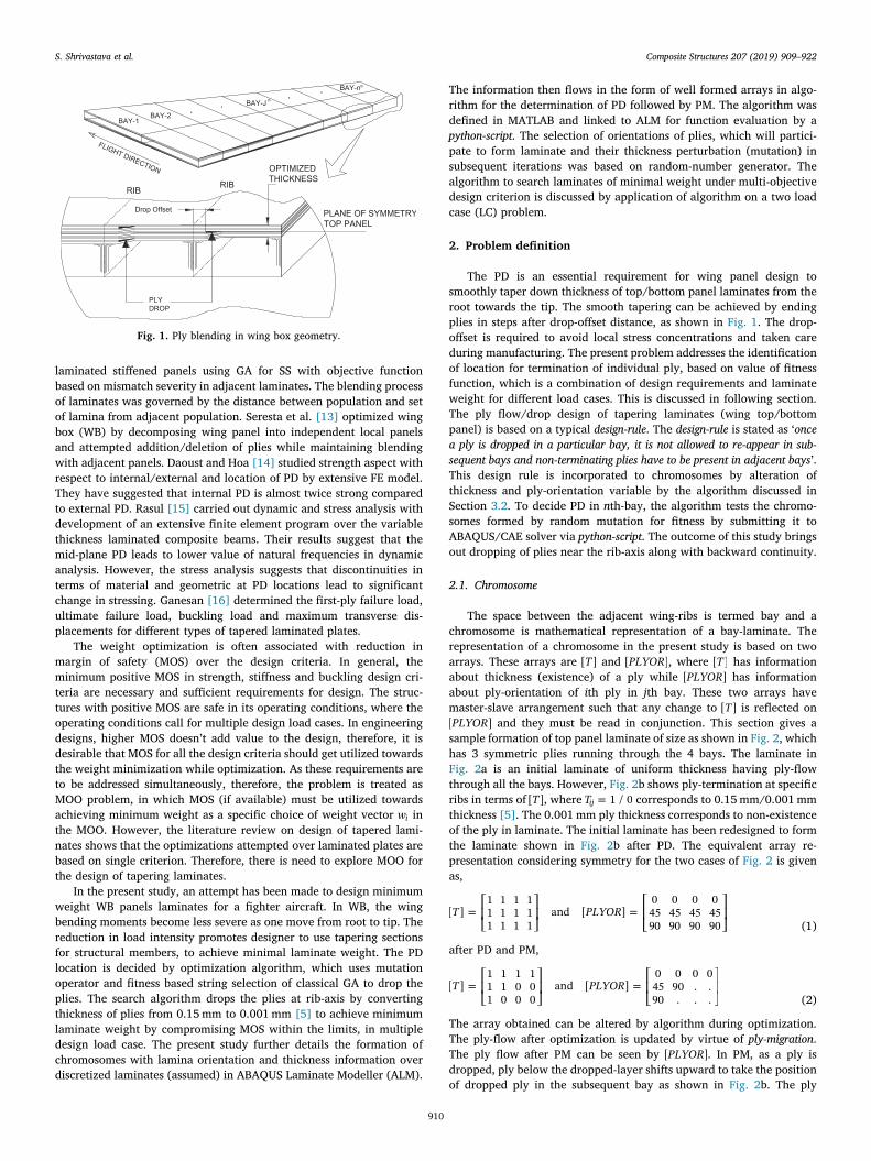
The PD is an essential requirement for wing panel design tosmoothly taper down thickness of top/bottom panel laminates from theroot towards the tip. The smooth tapering can be achieved by endingplies in steps after drop-offset distance, as shown in Fig. 1. The drop-offset is required to avoid local stress concentrations and taken careduring manufacturing. The present problem addresses the identificationof location for termination of individual ply, based on value of fitnessfunction, which is a combination of design requirements and laminateweight for different load cases. This is discussed in following section.The ply flow/drop design of tapering laminates (wing top/bottompanel) is based on a typical design-rule. The design-rule is stated as ‘oncea ply is dropped in a particular bay, it is not allowed to re-appear in sub-sequent bays and non-terminating plies have to be present in adjacent bays’.This design rule is incorporated to chromosomes by alteration ofthickness and ply-orientation variable by the algorithm discussed inSection 3.2. To decide PD in nth-bay, the algorithm tests the chromo-somes formed by random mutation for fitness by submitting it toABAQUS/CAE solver via python-script. The outcome of this study bringsout dropping of plies near the rib-axis along with backward continuity.
2.1. Chromosome
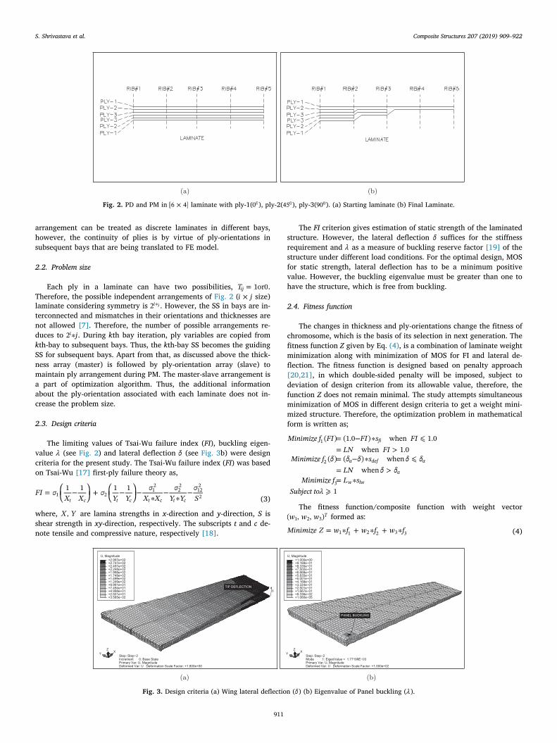
The space between the adjacent wing-ribs is termed bay and achromosome is mathematical representation of a bay-laminate. Therepresentation of a chromosome in the present study is based on twoarrays. These arrays are T[ ] and PLYOR[ ], where T[ ] has informationabout thickness (existence) of a ply while PLYOR[ ] has informationabout ply-orientation of ith ply in jth bay. These two arrays havemaster-slave arrangement such that any change to T[ ] is reflected onPLYOR[ ] and they must be read in conjunction. This section gives asample formation of top panel laminate of size as shown in Fig. 2, whichhas 3 symmetric plies running through the 4 bays. The laminate inFig. 2a is an initial laminate of uniform thickness having ply-flowthrough all the bays. However, Fig. 2b shows ply-termination at specificribs in terms of T[ ], where =T 1 / 0ij corresponds to 0.15mm/0.001mmthickness [5]. The 0.001mm ply thickness corresponds to non-existenceof the ply in laminate. The initial laminate has been redesigned to formthe laminate shown in Fig. 2b after PD. The equivalent array re-presentation considering symmetry for the two cases of Fig. 2 is givenas,
= =T PLYOR[ ]1 1 1 11 1 1 11 1 1 1
and [ ]0 0 0 045 45 45 4590 90 90 90 (1)
after PD and PM,
= =T PLYOR[ ]1 1 1 11 1 0 01 0 0 0
and [ ]0 0 0 045 90 . .90 . . . (2)
The array obtained can be altered by algorithm during optimization.The ply-flow after optimization is updated by virtue of ply-migration.The ply flow after PM can be seen by PLYOR[ ]. In PM, as a ply isdropped, ply below the dropped-layer shifts upward to take the positionof dropped ply in the subsequent bay as shown in Fig. 2b. The ply
Fig. 1. Ply blending in wing box geometry.
S. Shrivastava et al. Composite Structures 207 (2019) 909–922
910
arrangement can be treated as discrete laminates in different bays,however, the continuity of plies is by virtue of ply-orientations insubsequent bays that are being translated to FE model.
2.2. Problem size
Each ply in a laminate can have two possibilities, =T 1or0ij .Therefore, the possible independent arrangements of Fig. 2 ( ×i j size)laminate considering symmetry is 2i j. However, the SS in bays are in-terconnected and mismatches in their orientations and thicknesses arenot allowed [7]. Therefore, the number of possible arrangements re-duces to j2i . During kth bay iteration, ply variables are copied fromkth-bay to subsequent bays. Thus, the kth-bay SS becomes the guidingSS for subsequent bays. Apart from that, as discussed above the thick-ness array (master) is followed by ply-orientation array (slave) tomaintain ply arrangement during PM. The master-slave arrangement isa part of optimization algorithm. Thus, the additional informationabout the ply-orientation associated with each laminate does not in-crease the problem size.
2.3. Design criteria
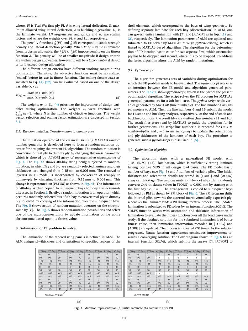
The limiting values of Tsai-Wu failure index (FI), buckling eigen-value (see Fig. 2) and lateral deflection (see Fig. 3b) were designcriteria for the present study. The Tsai-Wu failure index (FI) was basedon Tsai-Wu [17] first-ply failure theory as,
= +FIX X Y Y X X Y Y S1 1 1 1
t c t c t c t c1 2
12
22
122
2 (3)
where, X Y, are lamina strengths in x-direction and y-direction, S isshear strength in xy-direction, respectively. The subscripts t and c de-note tensile and compressive nature, respectively [18].
The FI criterion gives estimation of static strength of the laminatedstructure. However, the lateral deflection suffices for the stiffnessrequirement and as a measure of buckling reserve factor [19] of thestructure under different load conditions. For the optimal design, MOSfor static strength, lateral deflection has to be a minimum positivevalue. However, the buckling eigenvalue must be greater than one tohave the structure, which is free from buckling.
2.4. Fitness function
The changes in thickness and ply-orientations change the fitness ofchromosome, which is the basis of its selection in next generation. Thefitness function Z given by Eq. (4), is a combination of laminate weightminimization along with minimization of MOS for FI and lateral de-flection. The fitness function is designed based on penalty approach[20,21], in which double-sided penalty will be imposed, subject todeviation of design criterion from its allowable value, therefore, thefunction Z does not remain minimal. The study attempts simultaneousminimization of MOS in different design criteria to get a weight mini-mized structure. Therefore, the optimization problem in mathematicalform is written as;
== >== >=
Minimize f FI FI s FILN FI
Minimize f sLN
Minimize f L sSubject to
( ) (1.0 ) when 1.0when 1.0
( ) ( ) whenwhen
1
fi
a def a
a
w lw
1
2
3
The fitness function/composite function with weight vectorw w w( , , )T
1 2 3 formed as:
= + +Minimize Z w f w f w f1 1 2 2 3 3 (4)
Fig. 2. PD and PM in ×[6 4] laminate with ply-1(00), ply-2(450), ply-3(900). (a) Starting laminate (b) Final Laminate.
Fig. 3. Design criteria (a) Wing lateral deflection ( ) (b) Eigenvalue of Panel buckling ( ).
S. Shrivastava et al. Composite Structures 207 (2019) 909–922
911
where, FI is Tsai-Wu first ply FI, is wing lateral deflection, a max-imum allowed wing lateral deflection, is buckling eigenvalue, Lw isthe laminate weight, LN large-number and s s,fi def and slw are scalingfactors and wi are the weights over FI, and Lw, respectively.
The penalty functions f FI( )1 and f ( )2 correspond to static strengthpenalty and lateral deflection penalty. When FI or value is deviatedfrom its design allowable, the f FI f( ), ( )1 2 impose penalty on the fitnessfunction Z. The penalty will be of smaller magnitude if design criteriaare within design allowables, however it will be a large-number if designcriteria exceed design allowables.
The different design criteria have different working ranges duringoptimization. Therefore, the objective functions must be normalized(scaled) before its use in fitness function. The scaling factors s x( )i as-sociated to Eq. (4) [22] can be evaluated based on one of the designvariable x( )c as
=s x max x min xmax x min x
( ) . ( ) . ( ). ( ) . ( )i
i i
c c (5)
The weights wi in Eq. (4) prioritize the importance of design vari-ables during optimization. The weights wi were fractions with
= wiN
i1 =1, where N is the number of objective functions. The weightvector selection and scaling factor estimation are discussed in Section5.1.
2.5. Random mutation: Transformation to dummy plies
The mutation operator of the classical GA using MATLAB randomnumber generator is developed here to form a random-mutation op-erator for designing the present PD algorithm. The random-mutation isconversion of real ply to dummy ply by changing thickness parameter,which is showed by PLYOR[ ] array of representative chromosome ofFig. 4. The Fig. 4a shows 4th-bay string being subjected to random-mutation, in which T2,4 andT7,4 are randomly selected laminae and theirthicknesses are changed from 0.15mm to 0.001mm. The removal oflayer(s) in FE model is incorporated by conversion of real-ply todummy-ply by changing thickness from 0.15mm to 0.001mm. Thischange is represented on PLYOR[ ] as shown in Fig. 4b. The informationof 4th-bay is then copied to subsequent bays to obey the design-rulediscussed in Section 2. Briefly, a random-mutation is an operator, whichperturbs randomly selected bits of ith-bay to convert real ply to dummyply followed by copying of the information over the subsequent bays.The Fig. 5 shows action of random-mutation operator on the chromo-some by T[ ]. The Fig. 5 shows random-mutation possibilities and selectone of the mutation-possibility to update information of the entirechromosome based upon its fitness value.
3. Submission of FE problem to solver
The lamination of the tapered wing panels is defined in ALM. TheALM assigns ply-thickness and orientations to specified regions of the
shell elements, which correspond to the bays of wing geometry. Bydefining separate laminate for each bay (discretization) in ALM, onecan govern entire lamination with T[ ] and PLYOR[ ] as in Eqs. (1) and(2), respectively. The lamination parameters of ALM are updated andsubmitted to FE solver by MATLAB through python-scripting, which islinked to MATLAB based algorithm. The algorithm for the determina-tion of PD location has to cater for two aspects; first, which orientationply has to be dropped and second, where it is to be dropped. To addressthe issue, algorithm alters the ALM by random mutations.
3.1. Python script
The algorithm generates sets of variables during optimization forwhich the FE problem needs to be evaluated. The python-script works asan interface between the FE model and algorithm generated para-meters. The Table 1 shows python-script, which is the part of the presentoptimization algorithm. The script solves the FE problem for MATLABgenerated parameters for a kth load case. The python-script reads vari-ables generated by MATLAB (line number 2). The line number 4 assignsparameters to ALM. Then the line numbers 6 and 15 submit the modelfor FE static and buckling analyses, respectively. At the end of static andbuckling solutions, the result files are written (line numbers 11 and 16).The result files were read by MATLAB to guide the algorithm for itsfurther generations. The script line number 4 is repeated for i = 1 tonumber-of-plies and j = 1 to number-of-bays to update the orientationsand ply-thicknesses of the laminate of each bay. The procedure togenerate such a python-script is discussed in [5].
3.2. Optimization algorithm
The algorithm starts with a generalized FE model with± ±[ 45, (0, 90, 45) ]4 lamination, which is sufficiently strong laminatehaving positive MOS in all design load cases. The FE model has Jnumber of bays (see Fig. 1) and I number of variable plies. The initialthickness and orientation details are stored in [TORG] and [AORG]arrays at this stage. The random mutation block of algorithm randomlyconverts D %P thickness values in [TORG] to 0.001 mm by starting withthe first bay i.e. =J 1. The arrangement is copied to subsequent baysfollowed by PM as shown by PM block of Fig. 6. The PM program shiftsthe internal plies towards the external (aerodynamically exposed) ply,whenever the laminate finds a PD during iterative process. The updatedlamination is submitted to FE solver by an internal function SOLVE. TheSOLVE function works with orientation and thickness information oflamination to evaluate the fitness function over all the load cases understudy. If the obtained solution for the submitted lamination is of betterfitness value, then lamination information recorded in [TORG] and[AORG] are updated. The process is repeated ITP times. As the solutionprogresses, fitness function experiences continuous improvement to-wards a converging solution. The flow diagram shown in Fig. 6 has aninternal function SOLVE, which submits the arrays T PLYOR[ ], [ ] to
Fig. 4. Mutation representation (a) Initial laminate (b) Laminate after PD.
S. Shrivastava et al. Composite Structures 207 (2019) 909–922
912
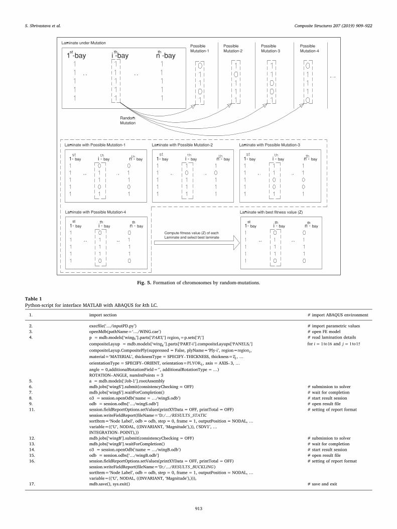
Fig. 5. Formation of chromosomes by random-mutations.
Table 1Python-script for interface MATLAB with ABAQUS for kth LC.
1. import section # import ABAQUS environment
2. execfile(‘…/inputPD.py’) # import parametric values3. openMdb(pathName=‘…/WING.cae’) # open FE model4. p =mdb.models[‘wingk’].parts[‘PARTi ’] regioni=p.sets[‘Pi’] # read lamination details
compositeLayup =mdb.models[‘wingk ’].parts[‘PART-i’].compositeLayups[‘PANELSi ’] for =i 1to 16 and =j 1to15compositeLayup.CompositePly(suppressed= False, plyName=‘Ply-i’, region=regioni,material=‘MATERIAL’, thicknessType= SPECIFY_THICKNESS, thickness=Tij , …orientationType= SPECIFY_ORIENT, orientation=PLYORij, axis=AXIS_3, …angle= 0,additionalRotationField=‘’, additionalRotationType=…)ROTATION_ANGLE, numIntPoints= 3
5. a =mdb.models[‘Job-1’].rootAssembly6. mdb.jobs[‘wingS’].submit(consistencyChecking=OFF) # submission to solver7. mdb.jobs[‘wingS’].waitForCompletion() # wait for completion8. o3 = session.openOdb(‘name=…/wingS.odb’) # start result session9. odb = session.odbs[‘…/wingS.odb’] # open result file11. session.fieldReportOptions.setValues(printXYData=OFF, printTotal=OFF) # setting of report format
session.writeFieldReport(fileName=‘D:/…/RESULTS STATIC_sortItem=‘Node Label’, odb= odb, step= 0, frame=1, outputPosition=NODAL, …variable=((‘U’, NODAL, ((INVARIANT, ‘Magnitude’),)), (‘SDV1’, …INTEGRATION_POINT),))
12. mdb.jobs[‘wingB’].submit(consistencyChecking=OFF) # submission to solver13. mdb.jobs[‘wingB’].waitForCompletion() # wait for completion14. o3 = session.openOdb(‘name=…/wingB.odb’) # start result session15. odb = session.odbs[‘…/wingB.odb’] # open result file16. session.fieldReportOptions.setValues(printXYData=OFF, printTotal=OFF) # setting of report format
session.writeFieldReport(fileName=‘D:/…/RESULTS BUCKLING_ )sortItem=‘Node Label’, odb= odb, step= 0, frame=1, outputPosition=NODAL, …variable=((‘U’, NODAL, ((INVARIANT, ‘Magnitude’),))),
17. mdb.save(), sys.exit() # save and exit
S. Shrivastava et al. Composite Structures 207 (2019) 909–922
913
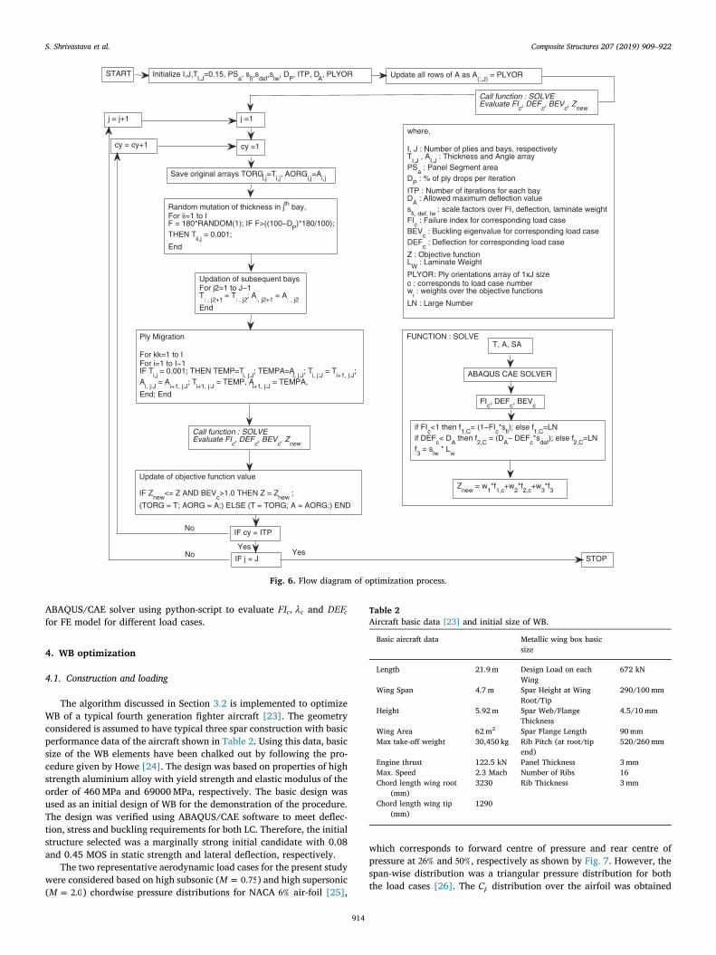
ABAQUS/CAE solver using python-script to evaluate FI ,c c and DEFcfor FE model for different load cases.
4. WB optimization
4.1. Construction and loading
The algorithm discussed in Section 3.2 is implemented to optimizeWB of a typical fourth generation fighter aircraft [23]. The geometryconsidered is assumed to have typical three spar construction with basicperformance data of the aircraft shown in Table 2. Using this data, basicsize of the WB elements have been chalked out by following the pro-cedure given by Howe [24]. The design was based on properties of highstrength aluminium alloy with yield strength and elastic modulus of theorder of 460MPa and 69000MPa, respectively. The basic design wasused as an initial design of WB for the demonstration of the procedure.The design was verified using ABAQUS/CAE software to meet deflec-tion, stress and buckling requirements for both LC. Therefore, the initialstructure selected was a marginally strong initial candidate with 0.08and 0.45 MOS in static strength and lateral deflection, respectively.
The two representative aerodynamic load cases for the present studywere considered based on high subsonic ( =M 0.75) and high supersonic( =M 2.0) chordwise pressure distributions for NACA 6% air-foil [25],
which corresponds to forward centre of pressure and rear centre ofpressure at 26% and 50%, respectively as shown by Fig. 7. However, thespan-wise distribution was a triangular pressure distribution for boththe load cases [26]. The Cp distribution over the airfoil was obtained
Fig. 6. Flow diagram of optimization process.
Table 2Aircraft basic data [23] and initial size of WB.
Basic aircraft data Metallic wing box basicsize
Length 21.9m Design Load on eachWing
672 kN
Wing Span 4.7 m Spar Height at WingRoot/Tip
290/100mm
Height 5.92m Spar Web/FlangeThickness
4.5/10mm
Wing Area 62m2 Spar Flange Length 90mmMax take-off weight 30,450 kg Rib Pitch (at root/tip
end)520/260mm
Engine thrust 122.5 kN Panel Thickness 3mmMax. Speed 2.3 Mach Number of Ribs 16Chord length wing root
(mm)3230 Rib Thickness 3mm
Chord length wing tip(mm)
1290
S. Shrivastava et al. Composite Structures 207 (2019) 909–922
914
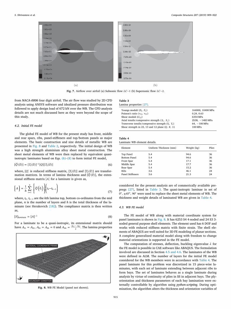
from NACA-0006 four digit airfoil. The air flow was studied by 2D CFDanalysis using ANSYS software and idealized pressure distribution wasfollowed to apply design load of 672 kN over the WB. The CFD analysisdetails are not much discussed here as they were beyond the scope ofthis study.
4.2. Initial FE model
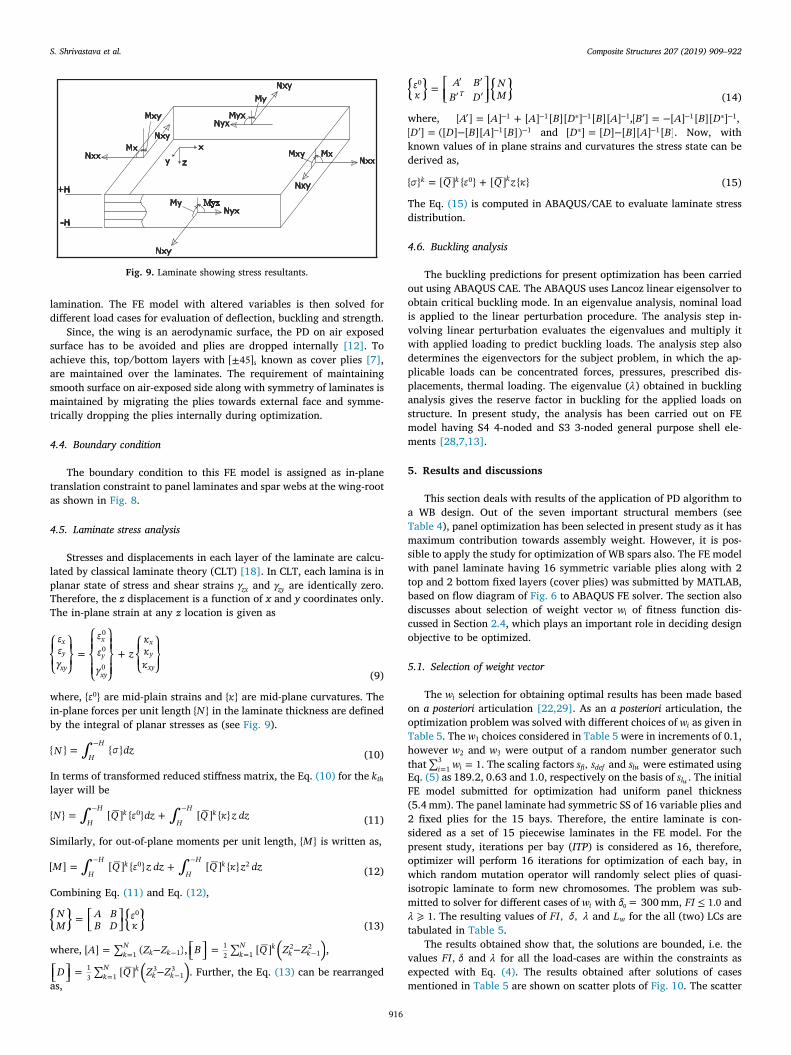
The global FE model of WB for the present study has front, middleand rear spars, ribs, panel-stiffeners and top/bottom panels as majorelements. The basic construction and size details of metallic WB arepresented in Fig. 8 and Table 2, respectively. The initial design of WBwas a high strength aluminium alloy sheet metal construction. Thesheet metal elements of WB were then replaced by equivalent quasi-isotropic laminates based on Eqs. (6)–(8) to form initial FE model,
=Q T Q T[ ( )] [ ( )] [ ][ ( )]11
2 (6)
where, Q[ ] is reduced stiffness matrix, [T ( )1 ] and [T ( )2 ] are transfor-mation matrices. In terms of lamina thickness and Q[ ( )], the exten-sional stiffness matrix A[ ] for a laminate is given as,
==
( )Ah
Q t t1
i
n
i k k1
1(7)
where, t t,k k 1 are the kth lamina top, bottom co-ordinates from the midplane, n is the number of layers and h is the total thickness of the la-minate (see Herakovich [18]). The compliance matrix is then writtenas,
=S A[ ] [ ]laminate1 (8)
For a laminate to be a quasi-isotropic, its extensional matrix shouldhave = = =A A A A, 011 22 16 26 and =A A A
66 211 12 . The lamina properties
considered for the present analysis are of commerically available pre-pregs [27], listed in Table 3. The quasi-isotropic laminae in set of° ± ° °0 , 45 , 90 were used to replace the sheet metal elements of WB. Thethickness and weight details of laminated WB are given in Table 4.
4.3. WB FE model
The FE model of WB along with material coordinate system forpanel laminates is shown in Fig. 8. It has 6253 S4 4-noded and 24 S3 3-noded general purpose shell elements. The element used has 6 DOF andworks with reduced stiffness matrix with finite strain. The shell ele-ments of ABAQUS are well suited for 3D FE modeling of planar sections.A complete generalized material model along with freedom to changematerial orientations is supported in the FE model.
The computation of stresses, deflection, buckling eigenvalue forthe FE model is possible in CAE software like ABAQUS. The formulationinvolved are discussed in Section 4.5 and 4.6. The laminates of the WBwere defined in ALM. The number of layers for the initial FE modelconsidered for the WB members were in accordance with Table 4. Thepanel laminate for this problem was discretized in 15 piece-wise la-minates, with each set of laminate extending between adjacent ribs toform bays. The set of laminates behaves as a single laminate duringanalysis by virtue of continuity of plies in SS in adjacent bays. The ply-orientation and thickness parameters of each bay lamination were ex-ternally controllable by algorithm using python-scripting. During opti-mization, the algorithm alters the thickness and orientation variables of
Fig. 7. Airflow over airfoil (a) Subsonic flow LC 1 (b) Supersonic flow LC 2.
Fig. 8. WB FE Model (panel not shown).
Table 3Lamina properties [27].
Youngs moduli (E E,1 2) 164000, 10400MPaPoisson’s ratio ( ,12 23) 0.24, 0.63Shear moduli (G12) 6354MPaAxial tensile/compressive strength (X X,t c) 2538, −1483MPaTransverse tensile/compressive strength (Y Y,t c) 64, −100MPaShear strength in 23, 13 and 12 plane (Q R S, , ) 100MPa
Table 4Laminate WB element details.
Element Uniform Thickness (mm) Weight (kg) Plies
Top Panel 5.4 94.6 36Bottom Panel 5.4 94.6 36Front Spar 5.4 17.1 36Middle Spar 5.4 17.7 36Rear Spar 5.4 15.2 36Ribs 3.6 46.1 24Panel Stiffeners 3.6 21.3 24
S. Shrivastava et al. Composite Structures 207 (2019) 909–922
915
lamination. The FE model with altered variables is then solved fordifferent load cases for evaluation of deflection, buckling and strength.
Since, the wing is an aerodynamic surface, the PD on air exposedsurface has to be avoided and plies are dropped internally [12]. Toachieve this, top/bottom layers with ±[ 45]s known as cover plies [7],are maintained over the laminates. The requirement of maintainingsmooth surface on air-exposed side along with symmetry of laminates ismaintained by migrating the plies towards external face and symme-trically dropping the plies internally during optimization.
4.4. Boundary condition
The boundary condition to this FE model is assigned as in-planetranslation constraint to panel laminates and spar webs at the wing-rootas shown in Fig. 8.
4.5. Laminate stress analysis
Stresses and displacements in each layer of the laminate are calcu-lated by classical laminate theory (CLT) [18]. In CLT, each lamina is inplanar state of stress and shear strains zx and zy are identically zero.Therefore, the z displacement is a function of x and y coordinates only.The in-plane strain at any z location is given as
= + zxy
xy
x
y
xy
xy
xy
0
0
0(9)
where, { }0 are mid-plain strains and { } are mid-plane curvatures. Thein-plane forces per unit length N{ } in the laminate thickness are definedby the integral of planar stresses as (see Fig. 9).
=N dz{ } { }H
H(10)
In terms of transformed reduced stiffness matrix, the Eq. (10) for the kthlayer will be
= +N Q dz Q z dz{ } [ ] { } [ ] { }H
H kH
H k0(11)
Similarly, for out-of-plane moments per unit length, M{ } is written as,
= +M Q z dz Q z dz[ ] [ ] { } [ ] { }H
H kH
H k0 2(12)
Combining Eq. (11) and Eq. (12),
={ } { }NM
A BB D
0
(13)
where, = =A Z Z[ ] ( )kN
k k1 1 , = = ( )B Q Z Z[ ]kN k
k k12 1
21
2 ,
= = ( )D Q Z Z[ ]kN k
k k13 1
31
3 . Further, the Eq. (13) can be rearrangedas,
= { }{ } A BB D
NMT
0
(14)
where, = +A A A B D B A[ ] [ ] [ ] [ ][ ] [ ][ ]1 1 1 1, =B A B D[ ] [ ] [ ][ ]1 1,=D D B A B[ ] ([ ] [ ][ ] [ ])1 1 and =D D B A B[ ] [ ] [ ][ ] [ ]1 . Now, with
known values of in plane strains and curvatures the stress state can bederived as,
= +Q Q z{ } [ ] { } [ ] { }k k k0 (15)
The Eq. (15) is computed in ABAQUS/CAE to evaluate laminate stressdistribution.
4.6. Buckling analysis
The buckling predictions for present optimization has been carriedout using ABAQUS CAE. The ABAQUS uses Lancoz linear eigensolver toobtain critical buckling mode. In an eigenvalue analysis, nominal loadis applied to the linear perturbation procedure. The analysis step in-volving linear perturbation evaluates the eigenvalues and multiply itwith applied loading to predict buckling loads. The analysis step alsodetermines the eigenvectors for the subject problem, in which the ap-plicable loads can be concentrated forces, pressures, prescribed dis-placements, thermal loading. The eigenvalue ( ) obtained in bucklinganalysis gives the reserve factor in buckling for the applied loads onstructure. In present study, the analysis has been carried out on FEmodel having S4 4-noded and S3 3-noded general purpose shell ele-ments [28,7,13].
5. Results and discussions
This section deals with results of the application of PD algorithm toa WB design. Out of the seven important structural members (seeTable 4), panel optimization has been selected in present study as it hasmaximum contribution towards assembly weight. However, it is pos-sible to apply the study for optimization of WB spars also. The FE modelwith panel laminate having 16 symmetric variable plies along with 2top and 2 bottom fixed layers (cover plies) was submitted by MATLAB,based on flow diagram of Fig. 6 to ABAQUS FE solver. The section alsodiscusses about selection of weight vector wi of fitness function dis-cussed in Section 2.4, which plays an important role in deciding designobjective to be optimized.
5.1. Selection of weight vector
The wi selection for obtaining optimal results has been made basedon a posteriori articulation [22,29]. As an a posteriori articulation, theoptimization problem was solved with different choices of wi as given inTable 5. The w1 choices considered in Table 5 were in increments of 0.1,however w2 and w3 were output of a random number generator suchthat == w 1i i1
3 . The scaling factors s s,fi def and slw were estimated usingEq. (5) as 189.2, 0.63 and 1.0, respectively on the basis of slw. The initialFE model submitted for optimization had uniform panel thickness(5.4mm). The panel laminate had symmetric SS of 16 variable plies and2 fixed plies for the 15 bays. Therefore, the entire laminate is con-sidered as a set of 15 piecewise laminates in the FE model. For thepresent study, iterations per bay (ITP) is considered as 16, therefore,optimizer will perform 16 iterations for optimization of each bay, inwhich random mutation operator will randomly select plies of quasi-isotropic laminate to form new chromosomes. The problem was sub-mitted to solver for different cases of wi with a= 300mm, FI 1.0 and
1. The resulting values of FI, , and Lw for the all (two) LCs aretabulated in Table 5.
The results obtained show that, the solutions are bounded, i.e. thevalues FI, and for all the load-cases are within the constraints asexpected with Eq. (4). The results obtained after solutions of casesmentioned in Table 5 are shown on scatter plots of Fig. 10. The scatter
Fig. 9. Laminate showing stress resultants.
S. Shrivastava et al. Composite Structures 207 (2019) 909–922
916

plots are for critical values of the two load cases between FI, vs Lw.The dotted line in the Fig. 10 shows front formed by non-dominatedsolutions. Since, the problem is focussed towards the laminate weightoptimization, the Cases 7, 13, 18–22, 25–27 and 34 are of interest, inwhich the results are near global optimal, i.e. laminate weight Lw is lessthan 88.0 kg. The points correspond to bottom-most points on thescatter plot as shown by the dotted circle in Fig. 10. In these solutions,the laminate weight is minimum along with minimum positive MOS indesign criteria. Out of these cases, the minimum weight is obtained forCase 20, in which the MOS for FI and lateral deflection is 0.001 and0.003, respectively, which indicates that the results are near to global
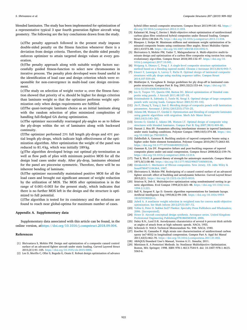
optima. Taking guideline from the weight vectors wi of Cases 7, 13,18–22, 25–27 and 34, the selection of wi is made as (0.45, 0.45, 0.1)T .The selected wi has w1 and w2 with equal values and it is higher than thevalue of w3. This enforces the algorithm to optimize the design criteriaat higher priority. Since, the present algorithm includes selection ofrandom plies while optimization, the problem was submitted to opti-mizer for multiple times with selected value of wi. The results obtaineddemonstrate the consistency of optimizer and achievement of a betterresult in the search process. The results obtained are discussed in nextsection.
Table 5Results with wi choices for two load cases.
Load case-1 Load case-2
Case w1 w2 w3 Lw(kg) FI (mm) FI (mm)
1 0.900 0.066 0.035 111.800 0.946 233.730 1.225 1.000 233.494 1.3402 0.900 0.094 0.006 117.825 0.934 253.030 1.130 1.000 249.900 1.2453 0.900 0.092 0.008 111.772 0.943 240.279 1.086 0.999 240.279 1.1864 0.900 0.094 0.007 113.802 0.948 239.543 1.154 1.000 240.073 1.3255 0.900 0.088 0.012 121.502 0.957 235.265 1.132 1.000 232.910 1.2406 0.800 0.120 0.080 91.080 0.918 262.763 1.001 0.999 263.380 1.0817 0.800 0.165 0.035 87.590 0.886 299.071 1.005 0.986 296.236 1.0828 0.800 0.096 0.104 93.605 0.929 248.654 1.019 1.000 248.194 1.2449 0.800 0.057 0.143 90.578 0.926 258.076 1.067 1.000 259.519 1.28210 0.800 0.084 0.116 98.365 0.939 252.477 1.017 1.000 252.594 1.25611 0.700 0.048 0.252 115.600 0.922 236.056 1.006 1.000 230.616 1.21712 0.700 0.030 0.270 114.880 0.940 233.034 1.004 1.000 231.590 1.22613 0.700 0.244 0.056 87.222 0.923 278.844 1.016 1.000 279.016 1.25914 0.700 0.293 0.007 93.046 0.918 274.557 1.028 1.000 273.892 1.17915 0.700 0.048 0.252 104.508 0.938 238.085 1.001 1.000 237.945 1.22416 0.600 0.252 0.148 89.612 0.931 266.208 1.000 0.989 267.200 1.08617 0.600 0.283 0.117 90.407 0.931 256.740 1.014 1.000 257.382 1.26218 0.600 0.326 0.074 87.222 0.923 278.844 1.016 1.000 279.016 1.25919 0.600 0.390 0.010 86.930 0.913 282.200 1.014 0.999 281.731 1.18020 0.600 0.340 0.060 84.610 0.916 298.923 1.005 0.999 299.110 1.11321 0.500 0.407 0.093 87.222 0.923 278.844 1.016 1.000 279.016 1.25922 0.500 0.485 0.015 87.385 0.917 283.012 1.001 0.991 278.786 1.26523 0.500 0.080 0.420 104.508 0.938 238.085 1.001 1.000 237.945 1.22424 0.500 0.012 0.488 95.843 0.935 241.848 1.003 1.000 242.813 1.21325 0.500 0.488 0.012 86.381 0.916 281.095 1.016 1.000 279.776 1.17926 0.400 0.489 0.111 87.222 0.923 278.844 1.016 1.000 279.016 1.25027 0.400 0.586 0.015 86.380 0.916 281.095 1.016 1.000 279.776 1.17928 0.400 0.096 0.504 104.508 0.938 238.085 1.001 1.000 237.945 1.22429 0.400 0.551 0.049 89.686 0.929 257.380 1.039 0.999 256.450 1.27330 0.400 0.348 0.253 94.689 0.943 256.309 1.002 1.000 254.310 1.22331 0.300 0.112 0.588 104.508 0.938 238.085 1.001 1.000 237.945 1.22432 0.300 0.017 0.683 95.843 0.935 241.840 1.003 1.000 242.813 1.21333 0.300 0.405 0.295 107.801 0.943 256.309 1.018 1.000 254.310 1.22334 0.300 0.519 0.182 86.340 0.928 299.772 1.002 0.994 299.429 1.15535 0.300 0.175 0.525 91.600 0.928 256.181 1.029 1.000 256.185 1.27736 0.200 0.593 0.207 93.479 0.928 299.772 1.002 0.994 299.429 1.15537 0.200 0.200 0.600 91.605 0.928 256.181 1.029 1.000 256.185 1.27738 0.200 0.198 0.602 94.758 0.945 250.096 1.032 1.000 249.539 1.22339 0.200 0.702 0.098 100.728 0.938 246.179 1.001 1.000 247.246 1.22340 0.200 0.474 0.326 97.708 0.929 265.223 1.000 0.982 265.320 1.090
Fig. 10. Scatter plot (a) Laminate weight vs Tsai Wu FI (b) Laminate weight vs deflection.
S. Shrivastava et al. Composite Structures 207 (2019) 909–922
917
5.2. Optimization results
Since the algorithm involves random selection of plies, the check forthe consistency of results with selected wi has been carried out.Therefore, the problem was submitted to optimizer for 8 times with wias (0.45, 0.45, 0. 1)T and rest of the parameters as discussed in Section5.2. The results obtained from multiple submission are placed at
Table 6. The results show that seven out of eight times the optimizerreached close to global optimal value, whereas only for one submissionoptimizer got stuck at some local optima.
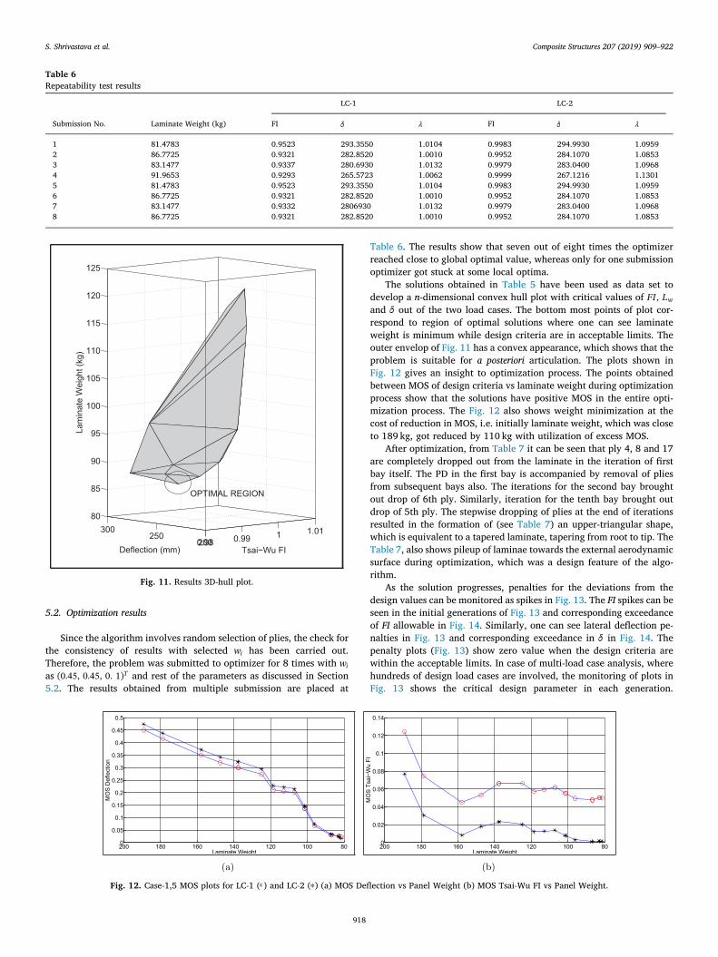
The solutions obtained in Table 5 have been used as data set todevelop a n-dimensional convex hull plot with critical values of FI L, wand out of the two load cases. The bottom most points of plot cor-respond to region of optimal solutions where one can see laminateweight is minimum while design criteria are in acceptable limits. Theouter envelop of Fig. 11 has a convex appearance, which shows that theproblem is suitable for a posteriori articulation. The plots shown inFig. 12 gives an insight to optimization process. The points obtainedbetween MOS of design criteria vs laminate weight during optimizationprocess show that the solutions have positive MOS in the entire opti-mization process. The Fig. 12 also shows weight minimization at thecost of reduction in MOS, i.e. initially laminate weight, which was closeto 189 kg, got reduced by 110 kg with utilization of excess MOS.
After optimization, from Table 7 it can be seen that ply 4, 8 and 17are completely dropped out from the laminate in the iteration of firstbay itself. The PD in the first bay is accompanied by removal of pliesfrom subsequent bays also. The iterations for the second bay broughtout drop of 6th ply. Similarly, iteration for the tenth bay brought outdrop of 5th ply. The stepwise dropping of plies at the end of iterationsresulted in the formation of (see Table 7) an upper-triangular shape,which is equivalent to a tapered laminate, tapering from root to tip. TheTable 7, also shows pileup of laminae towards the external aerodynamicsurface during optimization, which was a design feature of the algo-rithm.
As the solution progresses, penalties for the deviations from thedesign values can be monitored as spikes in Fig. 13. The FI spikes can beseen in the initial generations of Fig. 13 and corresponding exceedanceof FI allowable in Fig. 14. Similarly, one can see lateral deflection pe-nalties in Fig. 13 and corresponding exceedance in in Fig. 14. Thepenalty plots (Fig. 13) show zero value when the design criteria arewithin the acceptable limits. In case of multi-load case analysis, wherehundreds of design load cases are involved, the monitoring of plots inFig. 13 shows the critical design parameter in each generation.
Table 6Repeatability test results
LC-1 LC-2
Submission No. Laminate Weight (kg) FI FI
1 81.4783 0.9523 293.3550 1.0104 0.9983 294.9930 1.09592 86.7725 0.9321 282.8520 1.0010 0.9952 284.1070 1.08533 83.1477 0.9337 280.6930 1.0132 0.9979 283.0400 1.09684 91.9653 0.9293 265.5723 1.0062 0.9999 267.1216 1.13015 81.4783 0.9523 293.3550 1.0104 0.9983 294.9930 1.09596 86.7725 0.9321 282.8520 1.0010 0.9952 284.1070 1.08537 83.1477 0.9332 2806930 1.0132 0.9979 283.0400 1.09688 86.7725 0.9321 282.8520 1.0010 0.9952 284.1070 1.0853
Fig. 11. Results 3D-hull plot.
Fig. 12. Case-1,5 MOS plots for LC-1 ( ) and LC-2 ( ) (a) MOS Deflection vs Panel Weight (b) MOS Tsai-Wu FI vs Panel Weight.
S. Shrivastava et al. Composite Structures 207 (2019) 909–922
918
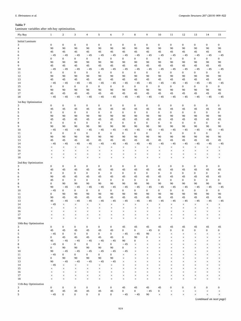
Table 7Laminate variables after nth-bay optimization.
Ply/Bay 1 2 3 4 5 6 7 8 9 10 11 12 13 14 15
Initial Laminate3 0 0 0 0 0 0 0 0 0 0 0 0 0 0 04 90 90 90 90 90 90 90 90 90 90 90 90 90 90 905 45 45 45 45 45 45 45 45 45 45 45 45 45 45 456 −45 −45 −45 −45 −45 −45 −45 −45 −45 −45 −45 −45 −45 −45 −457 0 0 0 0 0 0 0 0 0 0 0 0 0 0 08 90 90 90 90 90 90 90 90 90 90 90 90 90 90 909 45 45 45 45 45 45 45 45 45 45 45 45 45 45 4510 −45 −45 −45 −45 −45 −45 −45 −45 −45 −45 −45 −45 −45 −45 −4511 0 0 0 0 0 0 0 0 0 0 0 0 0 0 012 90 90 90 90 90 90 90 90 90 90 90 90 90 90 9013 45 45 45 45 45 45 45 45 45 45 45 45 45 45 4514 −45 −45 −45 −45 −45 −45 −45 −45 −45 −45 −45 −45 −45 −45 −4515 0 0 0 0 0 0 0 0 0 0 0 0 0 0 016 90 90 90 90 90 90 90 90 90 90 90 90 90 90 9017 45 45 45 45 45 45 45 45 45 45 45 45 45 45 4518 −45 −45 −45 −45 −45 −45 −45 −45 −45 −45 −45 −45 −45 −45 −45
1st-Bay Optimization3 0 0 0 0 0 0 0 0 0 0 0 0 0 0 04 45 45 45 45 45 45 45 45 45 45 45 45 45 45 455 0 0 0 0 0 0 0 0 0 0 0 0 0 0 06 90 90 90 90 90 90 90 90 90 90 90 90 90 90 907 45 45 45 45 45 45 45 45 45 45 45 45 45 45 458 0 0 0 0 0 0 0 0 0 0 0 0 0 0 09 90 90 90 90 90 90 90 90 90 90 90 90 90 90 9010 −45 −45 −45 −45 −45 −45 −45 −45 −45 −45 −45 −45 −45 −45 −4511 0 0 0 0 0 0 0 0 0 0 0 0 0 0 012 90 90 90 90 90 90 90 90 90 90 90 90 90 90 9013 45 45 45 45 45 45 45 45 45 45 45 45 45 45 4514 −45 −45 −45 −45 −45 −45 −45 −45 −45 −45 −45 −45 −45 −45 −4515 × × × × × × × × × × × × × × ×16 × × × × × × × × × × × × × × ×17 × × × × × × × × × × × × × × ×18 × × × × × × × × × × × × × × ×
2nd-Bay Optimization3 0 0 0 0 0 0 0 0 0 0 0 0 0 0 04 45 45 45 45 45 45 45 45 45 45 45 45 45 45 455 0 0 0 0 0 0 0 0 0 0 0 0 0 0 06 90 45 45 45 45 45 45 45 45 45 45 45 45 45 457 45 0 0 0 0 0 0 0 0 0 0 0 0 0 08 0 90 90 90 90 90 90 90 90 90 90 90 90 90 909 90 −45 −45 −45 −45 −45 −45 −45 −45 −45 −45 −45 −45 −45 −4510 −45 0 0 0 0 0 0 0 0 0 0 0 0 0 011 0 90 90 90 90 90 90 90 90 90 90 90 90 90 9012 90 45 45 45 45 45 45 45 45 45 45 45 45 45 4513 45 −45 −45 −45 −45 −45 −45 −45 −45 −45 −45 −45 −45 −45 −4514 −45 × × × × × × × × × × × × × ×15 × × × × × × × × × × × × × × ×16 × × × × × × × × × × × × × × ×17 × × × × × × × × × × × × × × ×18 × × × × × × × × × × × × × × ×
10th-Bay Optimization3 0 0 0 0 0 0 45 45 45 45 45 45 45 45 454 45 45 45 45 45 45 0 0 −45 0 0 0 0 0 05 −45 0 0 0 0 0 −45 −45 90 × × × × × ×6 0 45 45 45 45 45 0 90 0 × × × × × ×7 45 −45 −45 −45 −45 −45 90 0 × × × × × × ×8 −45 0 0 0 0 0 −45 × × × × × × × ×9 0 90 90 90 90 90 0 × × × × × × × ×10 90 −45 −45 −45 −45 −45 −45 × × × × × × × ×11 −45 0 0 0 0 0 × × × × × × × × ×12 0 90 90 90 90 90 × × × × × × × × ×13 90 −45 −45 −45 −45 −45 × × × × × × × × ×14 −45 × × × × × × × × × × × × × ×15 × × × × × × × × × × × × × × ×16 × × × × × × × × × × × × × × ×17 × × × × × × × × × × × × × × ×18 × × × × × × × × × × × × × × ×
11th-Bay Optimization3 0 0 0 0 0 0 45 45 45 45 0 0 0 0 04 45 45 45 45 45 45 0 0 −45 0 × × × × ×5 −45 0 0 0 0 0 −45 −45 90 × × × × × ×
(continued on next page)
S. Shrivastava et al. Composite Structures 207 (2019) 909–922
919

Therefore, these plots address the design parameter and load case re-sponsible for non-convergence of solution.
The algorithm for present problem is designed in such a way thatthe deviation of any of the design criteria generate penalty, which
prevents the solution to be accepted in the next generation. In thisprocess, if a solution is better, then only it is accepted in the iterativeprocess and its fitness value becomes benchmark for the entry of nextsolution. The next solution that appears in the iterative process will be
Fig. 14. Monitoring of solution convergence for Case-5 (a) LC-1 (b) LC-2.
Fig. 13. Monitoring of penalties for Case-5 (a) LC-1 (b) LC-2.
Table 7 (continued)
Ply/Bay 1 2 3 4 5 6 7 8 9 10 11 12 13 14 15
6 0 45 45 45 45 45 0 90 0 × × × × × ×7 45 −45 −45 −45 −45 −45 90 0 × × × × × × ×8 −45 0 0 0 0 0 −45 × × × × × × × ×9 0 90 90 90 90 90 0 × × × × × × × ×10 90 −45 −45 −45 −45 −45 −45 × × × × × × × ×11 −45 0 0 0 0 0 × × × × × × × × ×12 0 90 90 90 90 90 × × × × × × × × ×13 90 −45 −45 −45 −45 −45 × × × × × × × × ×14 −45 × × × × × × × × × × × × × ×15 × × × × × × × × × × × × × × ×16 × × × × × × × × × × × × × × ×17 × × × × × × × × × × × × × × ×18 × × × × × × × × × × × × × × ×
15th-Bay Optimization3 0 0 0 0 0 0 45 45 45 45 0 0 0 × ×4 45 45 45 45 45 45 0 0 −45 0 × × × × ×5 −45 0 0 0 0 0 −45 −45 90 × × × × × ×6 0 45 45 45 45 45 0 90 0 × × × × × ×7 45 −45 −45 −45 −45 −45 90 0 × × × × × × ×8 −45 0 0 0 0 0 −45 × × × × × × × ×9 0 90 90 90 90 90 0 × × × × × × × ×10 90 −45 −45 −45 −45 −45 −45 × × × × × × × ×11 −45 0 0 0 0 0 × × × × × × × × ×12 0 90 90 90 90 90 × × × × × × × × ×13 90 −45 −45 −45 −45 −45 × × × × × × × × ×14 −45 × × × × × × × × × × × × × ×15 × × × × × × × × × × × × × × ×16 × × × × × × × × × × × × × × ×17 × × × × × × × × × × × × × × ×18 × × × × × × × × × × × × × × ×
S. Shrivastava et al. Composite Structures 207 (2019) 909–922
920
accepted only if the value of fitness function is better than the previousone. The Fig. 14 shows monitoring of design parameters along with thelaminate (panel) weight (top and bottom). The laminate weight was189 kg at the start of solution, which slowly reduces as the solutionprogresses. At the end of optimization the weight of panel was 81.4 kg,which is 57% less than the initial weight. During optimization, MOS inFI and was initially 0.08 and 0.45, respectively, which was utilizedtowards the weight optimization. The respective MOS safety valuesafter optimization were 0.001 and 0.003, which show MOO in thepresent problem. Sometimes, less MOS can be mislead as a weakstructure, however, it is not the case and it has to be considered thatexcess MOS doesn't add value to the design. Moreover, if the designerwishes to have more MOS, then the design allowable (target value) canbe altered in the present optimizer. Therefore, the beauty of the presentoptimizer lies in achieving the target value for the design criteria andthereby leaving the minimum MOS.
5.3. Independent solution of FE optimal model
The FE analysis has been carried out for the optimal SS withoutdummy plies in ABAQUS/CAE and the solution was verified for dif-ferent load cases and design criteria. The results obtained by the in-dependent FE model solution and those obtained by the algorithmbased solution were in close match. The close match indicates that in-troduction of dummy plies (0.001mm thickness) within laminate hasno adverse affect over the FE model and results are bounded with andwithout dummy plies [5].
5.4. Lamination
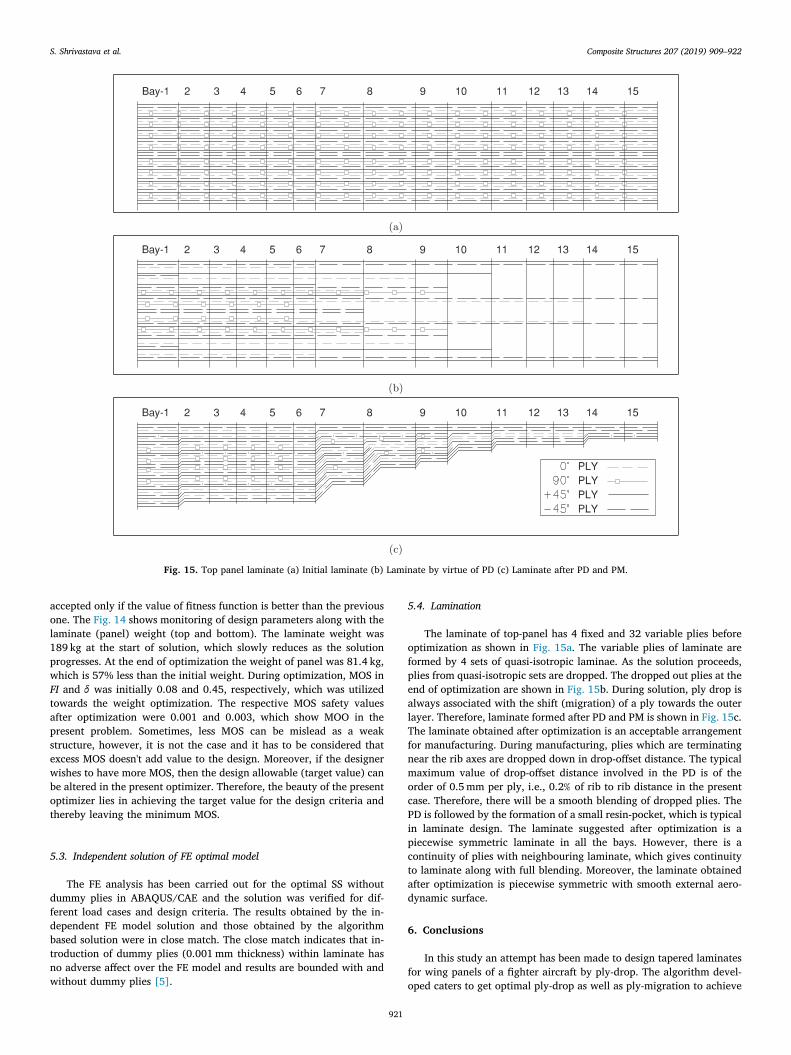
The laminate of top-panel has 4 fixed and 32 variable plies beforeoptimization as shown in Fig. 15a. The variable plies of laminate areformed by 4 sets of quasi-isotropic laminae. As the solution proceeds,plies from quasi-isotropic sets are dropped. The dropped out plies at theend of optimization are shown in Fig. 15b. During solution, ply drop isalways associated with the shift (migration) of a ply towards the outerlayer. Therefore, laminate formed after PD and PM is shown in Fig. 15c.The laminate obtained after optimization is an acceptable arrangementfor manufacturing. During manufacturing, plies which are terminatingnear the rib axes are dropped down in drop-offset distance. The typicalmaximum value of drop-offset distance involved in the PD is of theorder of 0.5mm per ply, i.e., 0.2% of rib to rib distance in the presentcase. Therefore, there will be a smooth blending of dropped plies. ThePD is followed by the formation of a small resin-pocket, which is typicalin laminate design. The laminate suggested after optimization is apiecewise symmetric laminate in all the bays. However, there is acontinuity of plies with neighbouring laminate, which gives continuityto laminate along with full blending. Moreover, the laminate obtainedafter optimization is piecewise symmetric with smooth external aero-dynamic surface.
6. Conclusions
In this study an attempt has been made to design tapered laminatesfor wing panels of a fighter aircraft by ply-drop. The algorithm devel-oped caters to get optimal ply-drop as well as ply-migration to achieve
Fig. 15. Top panel laminate (a) Initial laminate (b) Laminate by virtue of PD (c) Laminate after PD and PM.
S. Shrivastava et al. Composite Structures 207 (2019) 909–922
921
blended laminates. The study has been implemented for optimization ofa representative typical 3 spar fourth generation fighter aircraft winggeometry. The following are the key conclusions drawn from the study.
(a)The penalty approach followed in the present study imposesdouble-sided penalty on the fitness function whenever there is adeviation from design criteria. Therefore, the double sided penaltyenforces optimizer to attain targeted design values at every gen-eration.(b)The penalty approach along with suitable weight factors suc-cessfully guided fitness-function to select new chromosomes initerative process. The penalty plots developed were found useful inthe identification of load case and design criterion which were re-sponsible for non-convergence in multi-load case design environ-ment.(c)The study on selection of weight vector wi over the fitness func-tion showed that priority of wi should be higher for design criterionthan laminate weight so that the optimizer performs weight opti-mization only when design requirements are fulfilled.(d)The quasi-isotropic laminate choice as an initial laminate alongwith the random selection of plies minimized complexities ofhandling full-fledged GA during optimization.(e)The optimizer successfully rearranged ply-angles so as to followthe ply-drops within the set of laminates along with backwardcontinuity.(f)The optimizer performed 23% full length ply-drops and 43% par-tial length ply-drops, which indicate high effectiveness of the opti-mization algorithm. After optimization the weight of the panel wasreduced to 81.4 kg, which was initially 189 kg.(g)The algorithm developed brings out optimal ply-termination aswell as flow path of plies with minimum positive MOS for all thedesign load cases under study. After ply-drop, laminates obtainedfor the panel are piecewise symmetric. Therefore, there will be noinherent bending of laminate.(h)The optimizer successfully maintained positive MOS for all theload cases and brought out significant amount of weight reductionby the utilization of MOS. The MOS after optimization is in therange of 0.001–0.003 for the present study, which indicates thatthere is no further MOS left in the design and the structure is opti-mized to full potential.(i)The algorithm is tested for its consistency and the solutions arefound to reach near global-optima for maximum number of cases.
Appendix A. Supplementary data
Supplementary data associated with this article can be found, in theonline version, athttps://doi.org/10.1016/j.compstruct.2018.09.004.
References
[1] Shrivastava S, Mohite PM. Design and optimization of a composite canard controlsurface of an advanced fighter aircraft under static loading. Curved Layered Struct2015;2(1):91–105. https://doi.org/10.1515/cls-2015-0006.
[2] Lee D, Morillo C, Oller S, Bugeda G, Onate E. Robust design optimisation of advance
hybrid (fiber metal) composite structures. Compos Struct 2013;99:181–92. https://doi.org/10.1016/j.compstruct.2012.11.033.
[3] Kalantari M, Dong C, Davies I. Multi-objective robust optimisation of unidirectionalcarbon/glass fibre reinforced hybrid composites under flexural loading. ComposStruct 2016;138:264–75. https://doi.org/10.1016/j.compstruct.2015.11.034.
[4] Blasques J, Stolpe M. Maximum stiffness and minimum weight optimization of la-minated composite beams using continuous fiber angles. Struct Multidisc Optim2011;43:573–88. https://doi.org/10.1007/s00158-010-0592-9.
[5] Shrivastava S, Mohite PM, Yadav T, Malagaudanvar A. Multi-objective multi-la-minate design and optimization of a carbon fibre composite wing torsion box usingevolutionary algorithm. Compos Struct 2018;185:132–47. https://doi.org/10.1016/j.compstruct.2017.10.041.
[6] Weigang A, Dianyu C, Peng J. A single-level composite structure optimizationmethod based on a blending tapered model. Chinese J Aeronaut 2013;26(4):943–7.
[7] Irisarri F, Lasseigne A, Lerroy F, Riche R. Optimal design of laminated compositestructures with ply drops using stacking sequence tables. Compos Struct2014;107:559–69.
[8] Mukherjee A, Varughese B. Design guidelines for ply drop-off in laminated com-posite structures. Compos Part B: Eng 2001;32(2):153–64. https://doi.org/10.1016/S1359-8368(00)00038-X.
[9] Liu D, Torpov VV, Querin OM, Barton DC. Bilevel optimization of blended com-posite wing panels. J Aircraft 2011;48:107–18.
[10] Kristinsdottir B, Zabinsky Z, Tuttle M, Neogi S. Optimal design of large compositepanels with varying loads. Compos Struct 2001;51:93–102.
[11] Jin P, Zhong X, Yang J, Sun Z. Blending design of composite panels with laminationparameters. Aeronaut J 2016;120(1233):1710–25.
[12] Adams DB, Watson LT, Gürdal Z. Optimization and blending of composite laminatesusing genetic algorithms with migration. Mech Adv Mater Struct2003;10(3):183–203.
[13] Seresta O, Gürdal Z, Adams DB, Watson LT. Optimal design of composite wingstructures with blended laminates. Compos Part B: Eng 2007;38(4):469–80.
[14] Daoust J, Hoa SV. Parameters affecting interlaminar stresses in tapered laminatesunder static loading conditions. Polymer Compos 1989;10(5):374–88. https://doi.org/10.1002/pc.750100515.
[15] Zabihollah A, Ganesan R. Buckling analysis of tapered composite beams using ahigher order finite element formulation. Polymer Compos 2010;29(17):2663–83.https://doi.org/10.1177/0731684409352124.
[16] Ganesan R, Liu DY. Progressive failure and post-buckling response of taperedcomposite plates under uni-axial compression. Compos Struct 2008;82(2):159–76.https://doi.org/10.1016/j.compstruct.2006.12.014.
[17] Tsai S, Wu E. A general theory of strength for anisotropic materials. Compos Mater1971;5(1):58–80. https://doi.org/10.1177/002199837100500106.
[18] Herakovich C. Mechanics of fibrous composites. New Jersey, US: John Wiley &Sons9780471106364; 1997.
[19] Shrivastava S, Mohite PM. Redesigning of a canard control surface of an advancedfighter aircraft: effect of buckling and aerodynamic behavior. Curved Layred Struct2015;2(1). https://doi.org/10.1515/cls-2015-0010.
[20] Srinivas N, Deb K. Multiobjective optimization using nondominated sorting in ge-netic algorithms. Evol Comput 1994;2(3):221–48. https://doi.org/10.1162/evco.1994.2.3.221.
[21] Ball N, Sargent P, Ige D. Genetic algorithm representations for laminate layups.Artificial Intelligence Eng 1993;8(2):99–108. https://doi.org/10.1016/0954-1810(93)90020-G.
[22] Jubril A. A nonlinear weight selection in weighted sum for convex multi-objectiveoptimization. Ser Math Inform 2012;27(3):357–72.
[23] Yefim G, Peter D. Sukhoi Su27 Flanker. Specialty Press Publishers and Wholesalers;2006. [Incorporated].
[24] Howe D. Aircraft conceptual design synthesis. Aerospace series. United Kingdom:Professional Engineering Publishing9781860583018; 2000.
[25] Daley B.N., Lord D.R. Aerodynamic charateristics of several 6 percent thick airfoilsat angles of attack from at high subsonic speeds. NACA; 1955.
[26] Schrenck O. NACA Technical Memorandum No. 948. NACA; 1940.[27] Koerber H, Camanho P. High strain rate characterisation of unidirectional carbon
epoxy im7-8552 in longitudinal compression. Compos Part A: Appl Sci Manuf2011;42(5):462–70. https://doi.org/10.1016/j.compositesa.2011.01.002.
[28] ABAQUS/Standard User’s Manual, Version 6.11. Simulia; 2011.[29] Miettinen K. A Posteriori Methods. In: Nonlinear Multiobjective Optimization.
Boston, MA: Springer; 1998. ISBN 978-1-4613-7544-9. doi: 10.1007/978-1-4615-5563-6.
S. Shrivastava et al. Composite Structures 207 (2019) 909–922
922