Optimal Design Adjustable Back Angle Controller (ABAC) design.pdfOptimal Design Adjustable Back...
37
Optimal Design Adjustable Back Angle Controller (ABAC) By Alaena Destefano Steven Frisk Raymond Pennoyer Team No. 8 Funded by: Rehabilitation Education Research Center Client Contact Information Dr. John Enderle University of Connecticut: Biomedical Engineering Department Program Director & Professor of Biomedical Engineering Bronwell Building, Room 217C 260 Glendale Road, Storrs, Connecticut 06269-2247 Voice: (860) 486-2500 Email: [email protected] Website: www.eng2.uconn.edu/~jenderle BME Program Homepage: www.bme.uconn.edu EMB Magazine Homepage: www.EMB-Magazine.bme.uconn.edu
Transcript of Optimal Design Adjustable Back Angle Controller (ABAC) design.pdfOptimal Design Adjustable Back...
Optimal Design Adjustable Back Angle Controller
(ABAC)
By Alaena Destefano
Steven Frisk Raymond Pennoyer
Team No. 8
Funded by: Rehabilitation Education Research Center
Client Contact Information Dr. John Enderle
University of Connecticut: Biomedical Engineering Department Program Director & Professor of Biomedical Engineering Bronwell Building,
Room 217C 260 Glendale Road, Storrs, Connecticut 06269-2247 Voice: (860) 486-2500
Email: [email protected]: www.eng2.uconn.edu/~jenderle
BME Program Homepage: www.bme.uconn.eduEMB Magazine Homepage: www.EMB-Magazine.bme.uconn.edu

Table of Contents Page 1. Optimal Design 3
1.1. Introduction 3 1.2. Subunits 5-20
1.2.1. Control Lever 5 1.2.2. Lever 5-6 1.2.3. Resistance Spring 7-8 1.2.4. Electric Circuit 8-14
1.2.4.1. Overview 8-9 1.2.4.2. Circuit Components 10-14
1.2.5. Electric Motor 14-15 1.2.6. Actuator 15-22 1.2.7. Support Frame 22-23 1.2.8. Testing the Design 23
1.3. Realistic Constraints 26-28 1.4. Safety Issues 28-30 1.5. Impact of Engineering Solutions 30-32 1.6. Life-Long Learning 33-34 1.7. References 35-36
Figures and Tables Figure 1 Flow Chart of Device Operation 4 Figure 2 Basic Inside Design of Handle 6 Figure 3 Push-to-Make Switch and Bracket Representation 6 Figure 4 Calculation of Input Force on Springs 7 Figure 5 Free Body Diagram of Control Lever 8 Figure 6 Circuit Schematic 9 Figure 7 Typical Rotary Potentiometer 10 Figure 8 Internal Workings of Rotary Potentiometer 11 Figure 9 LM324 Quad Op Amp 11 Figure 10 MOSFET 12 Figure 11 PSPICE Simulation of Comparator Output 13 Figure 12 MOSFET Switching response to PWM 14 Figure 13 Circuit for a Series Wound DC Motor 15 Figure 14 Lead Screw Drive System 16 Figure 15 Diagram of Scissor Jack Lifting Bed 17 Figure 16 Free Body Diagram of Lifting System 17 Figure 17 Free Body of Scissor Jack 18 Figure 18 Diagram of Forces on Scissor Jack 19 Figure 19 Acceptable Travel Rate vs. Length for Screws 21 Figure 20 Ball Screw 21 Figure 21 Linear Actuator Mounting Bracket 22
1

Figure 22 Properties of Aluminum-Beryllium 80/20 22 Figure 23 Overall Schematic at 0° Angle 24 Figure 24 Overall Back and Side Schematic at 70° Angle 25 Table 1 Proposed Budget 32
2

Optimal Design 1.1. Introduction
Nursing is among one of the highest risk occupations for the development of back pain and injuries. Currently 17% of nurses experience chronic back pain due to working in a hospital setting. 36% of these back injuries in nurses can be contributed to patient handling. In addition to the back pain, women are also twice as likely to contract musculoskeletal disorders from the following work tasks: repeatedly lifting greater than 7 lbs, lifting patients more than 10 times per hour, making beds normally or often, and pushing beds or trolleys more than 10 minutes per day [1]. These daily tasks cannot be avoided; however, by the implementation of an automatic adjustable bed, nurses will incur less stress on their back during the adjustment of the patient.
Patients that suffer from back pain, obesity, and other debilitating diseases,
require an inclined bed back to relieve pain or provide easy access to the bed. Current technology includes an adjustable bed back with a remote control that is accessible for both the patient and the caretaker. However, this does not accommodate users of all disabilities. For example, a patient with limited sight may find it difficult to find the remote or press the correct buttons to operate the bed. Some of the current beds that may operate at higher speeds are rough or jerky when stopped in position. This erratic movement also occurs in beds that have more than one speed.
The Adjustable Back Angle Controller will improve upon the current
methods of adjusting a bed. This device will be controlled with a force sensitive handle located on the most accessible side of the bed. The basic concept of adjusting the back angle will take the input force on the handle and adjust the speed proportional to the force applied to the handle, i.e., more force on the handle outputs a faster speed to raise or lower the back angle. This concept works by adjusting the voltage supplied to a linear actuator with a potentiometer in the joint of the handle. This design will accommodate those with limited mobility and control; as well as prevent injuries to caretakers that attempt to sit the patients upright. The variable speed motor will control the actuator from zero to a safe maximum speed. This will allow for a smoother operation while still offering speedy adjustments when necessary. Overall this device will be user-friendly, smoother in operation, and less time consuming, making the operation less stressful. This operation is summarized in Figure 1.
3

Figure 1: Flow Chart of Device Operation
4

This report contains details of each subunit of the device, the testing of the subunits, how safety is being addressed in the design, the impact of the design, and how this project has educated the designers. It mainly differs from the previous report in that the new design has a slightly different layout so that the worm gear screw drive is lying horizontal, just below the bed. On that screw drive is a rod linked from the track to the bed frame. When the motor powers the screw drive, the track will push the rod and in turn raise or lower the bed. The motor is still driven by an electric circuit which has been designed to control the screw drives movement. The circuit has been altered such that it uses a pulse width modulation control to vary the speed and direction of the dc motor. The motor will then power the screw drive to raise and lower the bed back.
1.2. Subunits
1.2.1 Control Lever
The control lever will consist of three main parts; a lever with a safety
switch, a potentiometer connected to a circuit, and two resistance springs. The lever will be approximately one foot long, and will be in the shape of a flattened “S”. Figure 2, next page, shows the preliminary shape which has been designed to keep the majority of the control lever below the surface of the bed, out of the way of both the patient and the care-giver, while still allowing easy access to the patient within the bed. The lever will be used to change the resistance of the potentiometer. The potentiometer will control circuit which will adjust the average voltage supplied to the electric motor. When the lever is pulled up, the potentiometer will vary the circuit to supply a positive voltage to the motor. This will then raise the back of the bed up. The opposite will occur when the lever is pressed down. The electric motor will rotate depending on the sign of the voltage. With a greater amount of deflection on the lever, the potentiometer will increase the voltage to the motor, which in turn increases the speed of the motor. The resistance springs serve a two fold function. First of all, they will return the lever to its zero position, which will maintain zero voltage sent to the motor, causing the motor not to move, and to lock with the use of an electromagnetic brake. Second, the springs will provide the proper resistance so that a specific force will be required to displace the lever a specified amount. Therefore, the greater force applied to the lever, the greater voltage sent to the motor and a greater output speed to the bed back.
1.2.2 Lever
The lever will be the object moved by the user to operate the Adjustable
Back Angle Controller. Its shape will be ergonomic, so as to make operation of
5
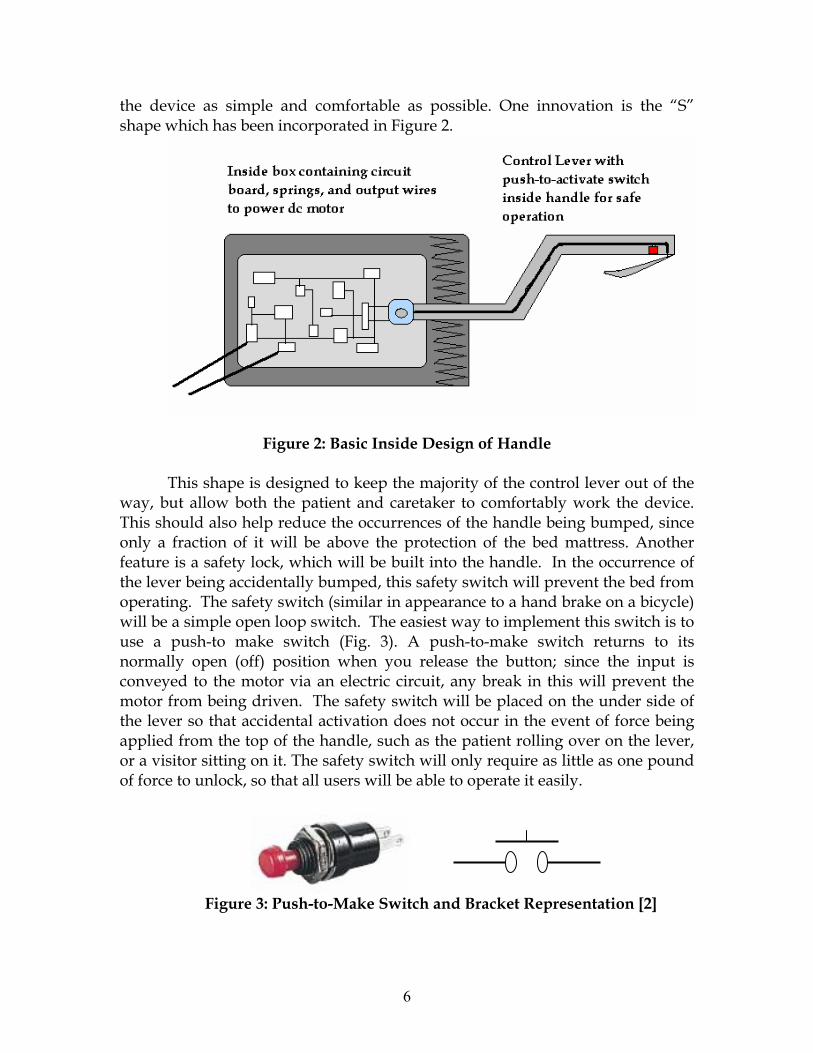
the device as simple and comfortable as possible. One innovation is the “S” shape which has been incorporated in Figure 2.
Figure 2: Basic Inside Design of Handle This shape is designed to keep the majority of the control lever out of the
way, but allow both the patient and caretaker to comfortably work the device. This should also help reduce the occurrences of the handle being bumped, since only a fraction of it will be above the protection of the bed mattress. Another feature is a safety lock, which will be built into the handle. In the occurrence of the lever being accidentally bumped, this safety switch will prevent the bed from operating. The safety switch (similar in appearance to a hand brake on a bicycle) will be a simple open loop switch. The easiest way to implement this switch is to use a push-to make switch (Fig. 3). A push-to-make switch returns to its normally open (off) position when you release the button; since the input is conveyed to the motor via an electric circuit, any break in this will prevent the motor from being driven. The safety switch will be placed on the under side of the lever so that accidental activation does not occur in the event of force being applied from the top of the handle, such as the patient rolling over on the lever, or a visitor sitting on it. The safety switch will only require as little as one pound of force to unlock, so that all users will be able to operate it easily.
Figure 3: Push-to-Make Switch and Bracket Representation [2]
6

1.2.3 Resistance Springs
The resistance springs are used in the control lever to bring the lever back to zero when the action is done, and to correlate an input force with an output displacement into the valves. To zero the lever, two springs with varying spring constants (k) will be attached between the lever, and opposite sides of the retaining box. The springs are to be sized such that both springs are stretched an equal amount when the lever is in the zero position. By stretching both springs even in at zero, makes both springs act equally on the lever at all times. Both springs must also be stretched even when the lever is at its maximal displacement to both sides. This is required so that the shorter spring does not begin to compress and push back against the lever, making calibrations less precise.
To design the proper control lever, the characteristics of the resistor circuit
system must be known. With a known spring displacement (Δx), and a known spring constant (k), the force required to displace the spring-lever is equal to the spring constant times the displacement (F=kΔx) as shown in Figure 4. For example, if the maximum displacement of the springs is one inch and knowing that the maximum force applied down is 20 lbs plus a small amount of weight from the handle, it can be calculated that the spring constant under the handle needed is just over twenty. This process may be more of a trial and error when it comes time to assemble.
(F=kΔx; where x2-x1=Δx) Figure 4: Calculation of Input Force on Springs
The force required to push at the end of the handle (P), can then be found
by drawing a basic free body diagram of the lever with springs as shown in Figure 5, and describing the moment about point A. By solving for P, the force to displace the lever some amount (x) is directly proportional to the force applied. To test the spring for the proper spring constant, the spring will be attached to an immobile surface. We will then measure its un-stretched length. A series of objects of known weight will then be hung from the spring, and the final stretched length of the spring will be measured. To solve for the spring constant
(k), F= kΔx can be rearranged to, x
FkΔ
= where Δx is the change in length
measured, and F is the weight of the object hung from it. After several repetitions, it will be possible to determine whether the spring truly does exert
7
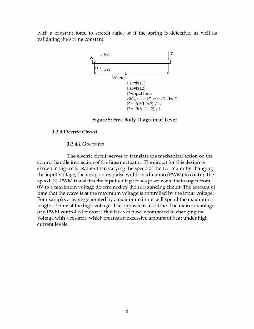
with a constant force to stretch ratio, or if the spring is defective, as well as validating the spring constant.
Where: Fs1=k(L1)
ce Fs2*l - Fs1*l
Figure 5: Free Body Diagram of Lever
1.2.4 Electric Circuit
1.2.4.1 Overview
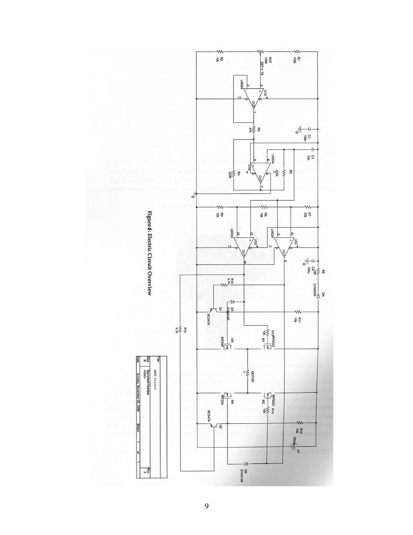
The electric circuit serves to translate the mechanical action on the contro andl
ng
f
Fs2=k(L2) P=input forΣMA = 0 = P*L+P = l*(Fs1-Fs2) / L P = l*k*(L1-L2) / L
l h e into action of the linear actuator. The circuit for this design is shown in Figure 6. Rather than varying the speed of the DC motor by changithe input voltage, the design uses pulse width modulation (PWM) to control the speed [3]. PWM translates the input voltage to a square wave that ranges from 0V to a maximum voltage determined by the surrounding circuit. The amount otime that the wave is at the maximum voltage is controlled by the input voltage. For example, a wave generated by a maximum input will spend the maximum length of time at the high voltage. The opposite is also true. The main advantageof a PWM controlled motor is that it saves power compared to changing the voltage with a resistor, which creates an excessive amount of heat under highcurrent levels.
8
9
1.2.4.2 Circuit Components
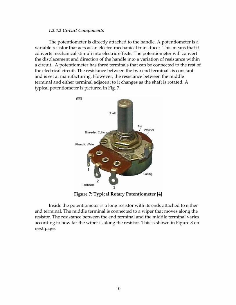
The potentiometer is directly attached to the handle. A potentiometer is a variable resistor that acts as an electro-mechanical transducer. This means that it converts mechanical stimuli into electric effects. The potentiometer will convert the displacement and direction of the handle into a variation of resistance within a circuit. A potentiometer has three terminals that can be connected to the rest of the electrical circuit. The resistance between the two end terminals is constant and is set at manufacturing. However, the resistance between the middle terminal and either terminal adjacent to it changes as the shaft is rotated. A typical potentiometer is pictured in Fig. 7.
Figure 7: Typical Rotary Potentiometer [4]
Inside the potentiometer is a long resistor with its ends attached to either end terminal. The middle terminal is connected to a wiper that moves along the resistor. The resistance between the end terminal and the middle terminal varies according to how far the wiper is along the resistor. This is shown in Figure 8 on next page.
10

Figure 8: Internal Workings of Rotary Potentiometer [5] The potentiometer is set up as a voltage divider circuit with middle pin connected to the non-inverting input of op amp U1A, which is an op amp configured as a voltage follower. Voltage followers have a gain very close to one and are used to safeguard the rest of the circuit from input extremes [6]. For this and all op amps in the circuit, the Vcc+ is supplied by the DC source, and Vcc- is ground. Optimally, all four op amps would be integrated into one IC chip, such as the LM324 quad op amp shown in Figure 9.
Figure 9: LM324 Quad Op Amp [7]
The output from the voltage follower is connected to the non-inverting
input of U1B, which is a triangle wave generator. The triangle wave is generated from the charging and discharging cycles of the 10nF capacitor. This value and the resistance of R6 create a triangle wave with a frequency of around 270 Hz. The Amplitude of the wave is controlled by the voltage follower.
The triangle wave is output to two op amps (U1C and U1D) set in window comparator configuration. It is connected to the non-inverting input of U1D and the inverting input of U1C. U1C is turned on if the triangle wave input
11
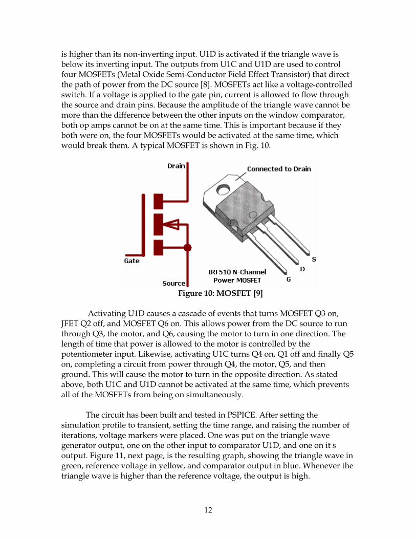
is higher than its non-inverting input. U1D is activated if the triangle wave is below its inverting input. The outputs from U1C and U1D are used to control four MOSFETs (Metal Oxide Semi-Conductor Field Effect Transistor) that direct the path of power from the DC source [8]. MOSFETs act like a voltage-controlled switch. If a voltage is applied to the gate pin, current is allowed to flow through the source and drain pins. Because the amplitude of the triangle wave cannot be more than the difference between the other inputs on the window comparator, both op amps cannot be on at the same time. This is important because if they both were on, the four MOSFETs would be activated at the same time, which would break them. A typical MOSFET is shown in Fig. 10.
Figure 10: MOSFET [9]
Activating U1D causes a cascade of events that turns MOSFET Q3 on, JFET Q2 off, and MOSFET Q6 on. This allows power from the DC source to run through Q3, the motor, and Q6, causing the motor to turn in one direction. The length of time that power is allowed to the motor is controlled by the potentiometer input. Likewise, activating U1C turns Q4 on, Q1 off and finally Q5 on, completing a circuit from power through Q4, the motor, Q5, and then ground. This will cause the motor to turn in the opposite direction. As stated above, both U1C and U1D cannot be activated at the same time, which prevents all of the MOSFETs from being on simultaneously.
The circuit has been built and tested in PSPICE. After setting the
simulation profile to transient, setting the time range, and raising the number of iterations, voltage markers were placed. One was put on the triangle wave generator output, one on the other input to comparator U1D, and one on it s output. Figure 11, next page, is the resulting graph, showing the triangle wave in green, reference voltage in yellow, and comparator output in blue. Whenever the triangle wave is higher than the reference voltage, the output is high.
12
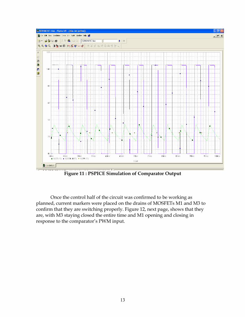
Figure 11 : PSPICE Simulation of Comparator Output
Once the control half of the circuit was confirmed to be working as planned, current markers were placed on the drains of MOSFETs M1 and M3 to confirm that they are switching properly. Figure 12, next page, shows that they are, with M3 staying closed the entire time and M1 opening and closing in response to the comparator’s PWM input.
13
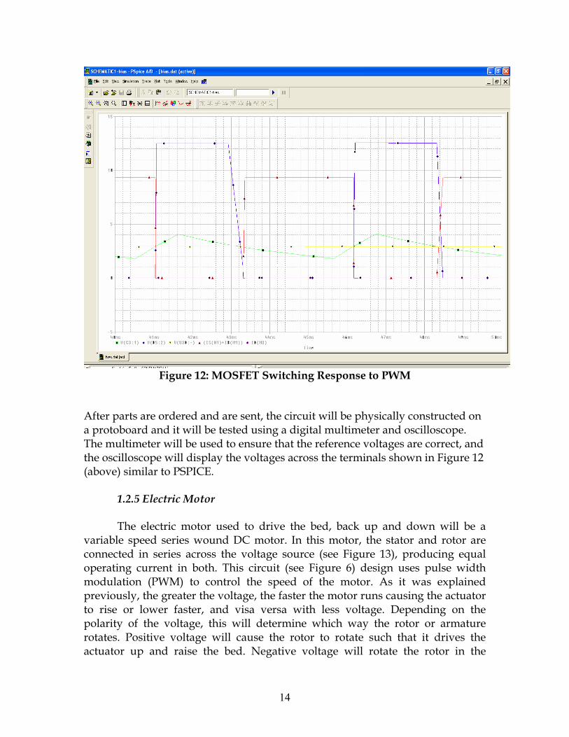
Figure 12: MOSFET Switching Response to PWM
After parts are ordered and are sent, the circuit will be physically constructed on a protoboard and it will be tested using a digital multimeter and oscilloscope. The multimeter will be used to ensure that the reference voltages are correct, and the oscilloscope will display the voltages across the terminals shown in Figure 12 (above) similar to PSPICE.
1.2.5 Electric Motor The electric motor used to drive the bed, back up and down will be a
variable speed series wound DC motor. In this motor, the stator and rotor are connected in series across the voltage source (see Figure 13), producing equal operating current in both. This circuit (see Figure 6) design uses pulse width modulation (PWM) to control the speed of the motor. As it was explained previously, the greater the voltage, the faster the motor runs causing the actuator to rise or lower faster, and visa versa with less voltage. Depending on the polarity of the voltage, this will determine which way the rotor or armature rotates. Positive voltage will cause the rotor to rotate such that it drives the actuator up and raise the bed. Negative voltage will rotate the rotor in the
14
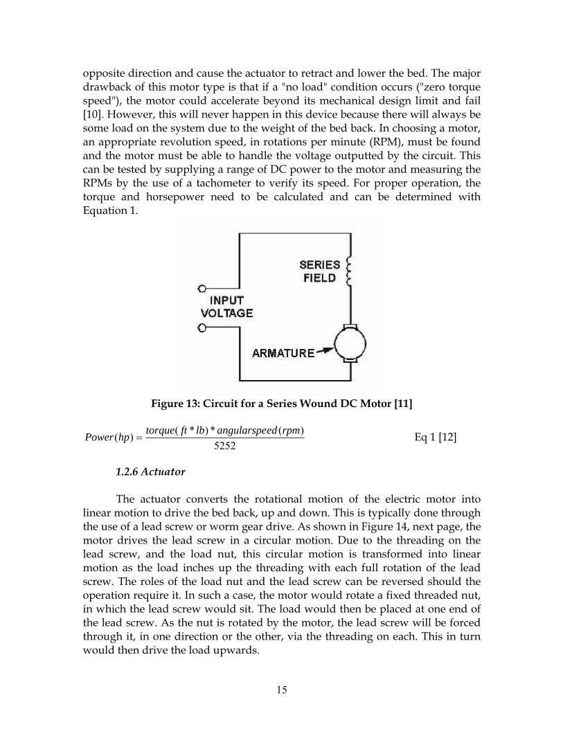
opposite direction and cause the actuator to retract and lower the bed. The major drawback of this motor type is that if a "no load" condition occurs ("zero torque speed"), the motor could accelerate beyond its mechanical design limit and fail [10]. However, this will never happen in this device because there will always be some load on the system due to the weight of the bed back. In choosing a motor, an appropriate revolution speed, in rotations per minute (RPM), must be found and the motor must be able to handle the voltage outputted by the circuit. This can be tested by supplying a range of DC power to the motor and measuring the RPMs by the use of a tachometer to verify its speed. For proper operation, the torque and horsepower need to be calculated and can be determined with Equation 1.
Figure 13: Circuit for a Series Wound DC Motor [11]
5252)(*)*()( rpmedangularspelbfttorquehpPower = Eq 1 [12]
1.2.6 Actuator
The actuator converts the rotational motion of the electric motor into linear motion to drive the bed back, up and down. This is typically done through the use of a lead screw or worm gear drive. As shown in Figure 14, next page, the motor drives the lead screw in a circular motion. Due to the threading on the lead screw, and the load nut, this circular motion is transformed into linear motion as the load inches up the threading with each full rotation of the lead screw. The roles of the load nut and the lead screw can be reversed should the operation require it. In such a case, the motor would rotate a fixed threaded nut, in which the lead screw would sit. The load would then be placed at one end of the lead screw. As the nut is rotated by the motor, the lead screw will be forced through it, in one direction or the other, via the threading on each. This in turn would then drive the load upwards.
15
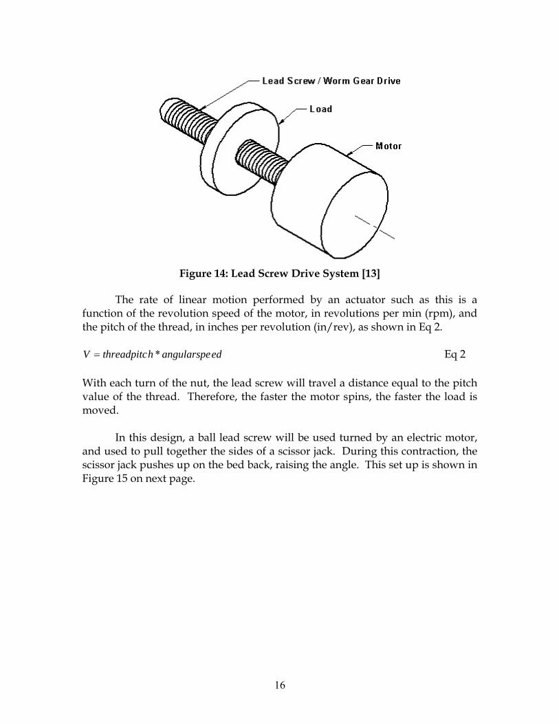
Figure 14: Lead Screw Drive System [13]
The rate of linear motion performed by an actuator such as this is a function of the revolution speed of the motor, in revolutions per min (rpm), and the pitch of the thread, in inches per revolution (in/rev), as shown in Eq 2.
edangularspehthreadpitcV *= Eq 2 With each turn of the nut, the lead screw will travel a distance equal to the pitch value of the thread. Therefore, the faster the motor spins, the faster the load is moved. In this design, a ball lead screw will be used turned by an electric motor, and used to pull together the sides of a scissor jack. During this contraction, the scissor jack pushes up on the bed back, raising the angle. This set up is shown in Figure 15 on next page.
16

θ
Figure 15: Diagram of Scissor Jack Lifting Bed Back
L
D
θ γ
h1
h2
Figure 16: Free Body Diagram of Lifting System
Where: h2 = Raise in bed at θ degree incline (D*sin(θ)) h1 = Length of Fully Retracted Scissor Jack θ = degree incline in bed back D = Distance of connection point from bed joint
γ = degree tilt of actuator at θ degree incline in bed back ( ⎟⎟⎠
⎞⎜⎜⎝
⎛+
−
21
1tanhh
L )
L = horizontal displacement of connection point (D*cos(θ))
17
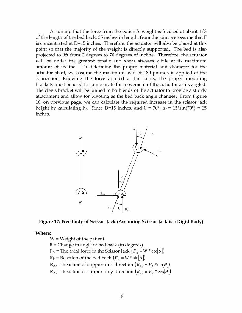
Assuming that the force from the patient’s weight is focused at about 1/3 of the length of the bed back, 35 inches in length, from the joint we assume that F is concentrated at D=15 inches. Therefore, the actuator will also be placed at this point so that the majority of the weight is directly supported. The bed is also projected to lift from 0 degrees to 70 degrees of incline. Therefore, the actuator will be under the greatest tensile and shear stresses while at its maximum amount of incline. To determine the proper material and diameter for the actuator shaft, we assume the maximum load of 180 pounds is applied at the connection. Knowing the force applied at the joints, the proper mounting brackets must be used to compensate for movement of the actuator as its angled. The clevis bracket will be pinned to both ends of the actuator to provide a sturdy attachment and allow for pivoting as the bed back angle changes. From Figure 16, on previous page, we can calculate the required increase in the scissor jack height by calculating h2. Since D=15 inches, and θ = 70°, h2 = 15*sin(70°) = 15 inches.
θ
W
RAy
W
W
FA
FA
Rb
RAx
θ
θ
Figure 17: Free Body of Scissor Jack (Assuming Scissor Jack is a Rigid Body)
Where: W = Weight of the patient θ = Change in angle of bed back (in degrees) FA = The axial force in the Scissor Jack [ ]( )θcos*WFA = Rb = Reaction of the bed back [ ]( )θsin*WFA = RAx = Reaction of support in x-direction [ ]( )θsin*AAx FR = RAy = Reaction of support in y-direction [ ]( )θcos*AAy FR =
18

FA
FA
F F
H
H
T T
γ
ω
L
Figure 18: Diagram of Forces on Scissor Jack
The following equations are used to calculate the force applied by the lead
screw.
⎟⎠⎞
⎜⎝⎛= −
TH1sinγ Eq 1
( )cos()cos(* 070 )γγ −=Δ TL Eq 2
( )
( )γγ
sincos*AF
F = Eq 3
Where: FA = The axial force in the Scissor Jack (From Figure _) T = Length of each Arm of Scissor Jack F = Force Applied by Lead Screw H = Half Height of jack L = Half the width of the jack ΔL = Change in L between 70 degree bed angle and 0 degree be angle γ70 = Angle at 70 degree bed angle
γ0 = Angle at 0 degree bed angle
19

In our design, the maximal force on the scissor jack will occur at an angle of 0°. Therefore, we use this case to determine the maximum power required by the motor. In this case, FA = W, for which 200 lbs can be used for a patient weight of 180 lbs and compensating for the weight of the bed. Also, T = 11 inches, and H at 0° is 2.5 in. By plugging these numbers into Equations 1 and 2, we find that the force required (F) is 852.74 lbs.
The following equations are use to calculate the torque and power required to drive the scissor jack at the required rate.
ρ**177.0 FT = Eq 4 [14]
510564.3**×
=nFP ρ Eq 5 [14]
Where: T = The torque required by the motor F = Force Applied by Lead Screw ρ = Thread pitch (in/rev) n = Desired rotational speed (rpm) Since we know F, only the thread pitch (ρ) and the rotational speed (n) needs to be determined. To get a 70 degree raise in the bed angle, we need the scissor jack to 16 inches. This means that H will go from 2.5 inches to 10.5 inches. Using these values, we can find the change in 2L (2*ΔL) for which the screw will travel. This value comes out to be 15 inches. At the maximum speed, we would like the bed to travel from flat to a 70 degree raise in 3 seconds, which means a velocity in the screw of 5 inches/sec. By trial and error, and the use of Figure 19 on next page, we found out the thread pitch should be 0.5 in/rev, and a 1 in diameter screw as shown in Figure 20 on next page. Therefore, to accomplish a 5 in/sec travel, the rotational speed would have to be
min/600in/rev 0.560sec/min*in/sec 5 rev= . Therefore, the torque required (T) will be 75.5
ft*lb, and the power (P) will be 0.718 hp.
20
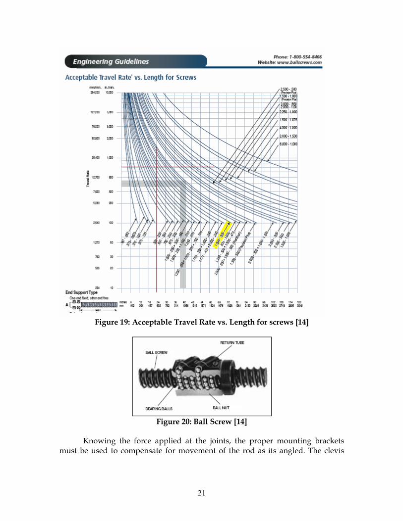
Figure 19: Acceptable Travel Rate vs. Length for screws [14]
Figure 20: Ball Screw [14]
Knowing the force applied at the joints, the proper mounting brackets must be used to compensate for movement of the rod as its angled. The clevis
21

bracket (Fig. 21) will be pinned to both ends of the Al-Be 80/20 rod to provide a sturdy attachment and allow for pivoting as the bed back angle changes.
Figure 21: Linear Actuator Mounting Bracket [15]
1.2.7 Support Frame
After understanding all the loads that this device needs to withstand, a strong support frame for the actuator can be determined. The most practical metal to use in this situation is Aluminum-Beryllium (Al-Be) 80/20. This is a light weight, durable, easy to assemble, and cheaper way to construct this verse welding steel parts together. Below in Figure 16 is a picture of Al-Be 80/20 and chart of its mechanical properties. The design of this structure is seen in the overview of the frame in Figure 23 and 24 on pages 22 and 23, respectively. This material will be ordered in the proper sizes and put together in the machine shop. Once the frame is finished, it will undergo a series of loading tests to test the strength of the structure. If failure is to occur, reinforcement will be added where necessary.
Nominal Density (lb./in3) 0.076 to 0.086 Yield (KSI) 23 to 40 Melting Point (°F) 2010 to 2150 Chemical Family Metal matrix Ultimate (KS) 34 to 55 Elongation (%) 17 to 7 Modulus (MSI) 19 to 28 Color Gray
Figure 22: Properties of Aluminum-Beryllium 80/20 [16][17]
The overall schematic of the design (as illustrated in the Microsoft VISIO drawings in Figures 23 and 24) demonstrates the pivoting of the actuator to allow for movement as the bed is operated and sustains a low profile when retracted. Also, the handle is positioned out of the way and designed for easy access. All parts are secured with bolts to the frame of the bed or the Aluminum.
22
To demonstrate the final workings of this automatic back angle controller, it will be fastened to a mock bed platform. It can be made out of scrap Al-Be 80/20 or welded with steel and have a metal platform attached to mimic the mattress. This will allow the device to be tested under the weight of humans lying on the platform.
1.2.8 Testing the Design
Once the subunits are assembled to create the bed back angle controller, the device needs to be tested for its functionality and reliability to ensure its safety. The handle design will undergo testing in the springs and the safety switch. The resistance springs must deflect the lever from its center position the correct amount without loosing their resilience. The spring constants will be tested by showing that when a 20 lb weight is hung from them, only one inch of the spring is stretched out. The safety switch of the handle is wired into the circuit and cuts off the power to the motor until the switch is turned on. This can be tested once the circuit is working properly. The circuit will be physically constructed on a protoboard and it will be tested using a digital multimeter and oscilloscope. The multimeter will be used to ensure that the reference voltages are correct, and the oscilloscope will display the voltages across the terminals. To ensure the motor is not drawing in a dangerous level of current from the circuit, the size of the worm gear lead screw is chosen specifically to not require a high level of torque to be powered. To confirm the torque and power needed by the motor to operate the scissor jack, the pitch of the screw can be measured with a ruler and it can be calculated with Equations 4 and 5.
When the basic components are tested individually the device can then be
assembled and tested as one unit. The handle design must be correctly wired to the motor. The motor must be secured onto the scissor screw jack and the screw jack must be properly attached to the frame of the bed back with pivoting mounting brackets. This device is setup on a prototype bed platform that will enable us to test its ability to adjust the back angle. The final test for the true workings of this device is to have a person lie down on the bed and operate the handle in both directions.
23

Figure 23: Overall Schematic at Zero degrees Angle
24
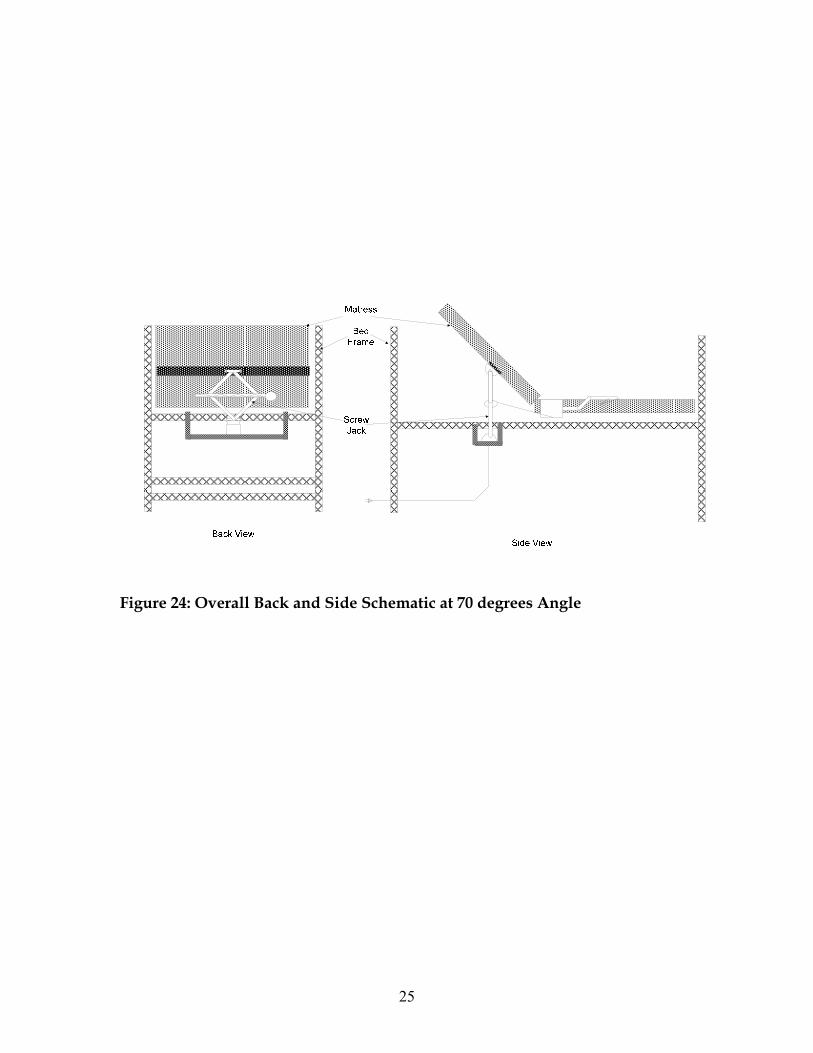
Figure 24: Overall Back and Side Schematic at 70 degrees Angle
25

Realistic Constraints Naturally, when designing a new device, there will be some constraints. The
only ethical concern is that this device must be designed with the patients and users safety in mind. Safety precautions are addressed in detail in the international standards and in the section below. For this design all materials used must be durable so that they can lift and hold up to 200lbs, be readily available, environmentally safe and be able to be sterilized. The rod that is being pushed by the screw drive actuator needs to be supported by a frame when being attached to the back. Otherwise, if too much force were applied to the rod and it was positioned in the middle of the bed back, it may break through the bed mattress, and in its worst case, stab the patient in the back.
With the implementation of the brush series wound DC motor, there are
concerns about the longevity of the brushing mechanism. However, this is not a major issue because it still has a considerable life span, especially for this low impact situation. With any load bearing device, the wear and tear on the screws and fixtures will also be a concern with the devices sustainability. Finally, the availability of the parts used in manufacturing the device was considered and it will be economically feasible for mass production.
According to internationally recognized quality and safety standards, there
are some constraints to consider when designing. The International Standards Organization (ISO) [18] and the International Electrotechnical Commission (IEC) develops rules to follow in order to reassure that the product is reliable and will meet expectations in terms of performance, safety, durability and other criteria. The following standards were taken from the IEC website because they closely match the building requirements of the adjustable bed design [19]:
• IEC 60073 Basic and safety principles for man-machine
interface, marking and identification - Coding principles for indicators and actuators. Establishes general rules for assigning particular meanings to certain visual, acoustsic and tactile indications. Has the status of a basic safety publication in accordance with IEC Guide 104.
• IEC 60364-4-41 Low-voltage electrical installations - Part 4-41: Protection for safety - Protection against electric shock. Specifies essential requirements regarding protection against electric shock, including basic protection (protection against direct contact) and fault protection (protection against indirect contact) of persons and livestock. It deals also with the application and co-ordination of these requirements in relation to external influences. Requirements are also given for the application of additional protection in certain cases.
26
• IEC 60447 Basic and safety principles for man-machine interface, marking and identification - Actuating principles. Establishes general actuating principles for manually operated actuators forming part of the man-machine interface associated with electrical equipment, in order to increase the safety through the safe operation of the equipment and facilitate the proper and timely operation of the actuators
• IEC 60529 Degrees of protection provided by enclosures (IP Code). Applies to the classification of degrees of protection provided by enclosures for electrical equipment with a rated voltage not exceeding 72.5 kV.
• IEC 60534-6-1 Industrial-process control valves - Part 6: Mounting details for attachment of positioners to control valves - Section 1: Positioner mounting on linear actuators. Intended to permit a variety of positioning devices, which respond to a linear motion, to be mounted on the actuator of a control valve, either directly or by employing an intermediate mounting bracket. Applicable where interchangeability between actuators and positioners is desired.
• IEC 60601-1 Medical Electrical Equipment: General Requirements for Safety. Applies to the safety of medical electrical systems, as defined as follows: combination of items of equipment, at least one of which must be medical electrical equipment and inter-connected by functional connection or use of a multiple portable socket-outlet. Describes the safety requirements necessary to provide protection for the patient, the operator and surroundings. Cancels and replaces the first edition published in 1992 and its amendment 1 (1995) and constitutes a technical revision.
• IEC 60601-1-2 Top Level standard for electromagnetic compatibility for electrical medical equipment.
• IEC 60601-1-6 Medical electrical equipment - Part 1-6: General requirements for safety - Collateral standard: Usability. This Collateral Standard describes a usability engineering process, and provides guidance on how to implement and execute the process to provide medical electrical equipment safety. It addresses normal use and use errors but excludes abnormal use.
• IEC 60601-2-38 Particular requirements for the safety of electrically operated Hospital beds. Specifies requirements for safety of electrically operated hospital beds. The object of this standard is to keep the safety hazards to patients, operators and the environment as low as possible, and to describe tests to verify that these requirements are attained.
• IEC 60601-2-46 Medical electrical equipment - Part 2-46: Particular requirements for the safety of operating tables. Specifies safety requirements for operating tables, whether or not having electrical parts,
27

including transporters used for the transportation of the table top to or from the base or pedestal of an operating table with detachable table top.
• IEC 61800-1 Adjustable speed electrical power drive systems - Part 1: General requirements - Rating specifications for low voltage adjustable speed DC power drive systems. Applies to general purpose adjustable speed DC driven systems which include the power conversion, control equipment, and also a motor or motors. Excluded are traction and electrical vehicle drives. Applies to power driven systems (PDS) connected to line voltages up to 1 kVAC, 50 Hz or 60 Hz.
• IEC 62955-1 Primary batteries - Summary of research and actions limiting risks to reversed installation of primary batteries. Provides information relevant to the safe design of batteries and battery powered devices together with appropriate cautionary advice to consumers. This report is primarily intended to be used by battery manufacturers, equipment manufacturers, designers, standard writers, consumer organizations, and charger manufacturers. This report may also be of assistance to educational authorities, users, procurement personnel, and regulatory authorities.
1.3. Safety Issues As with all engineering projects, the safety of the hospital bed’s user is
paramount. This project is designed for widespread use, and if even one patient or caretaker is significantly injured, then it is a failure. The device will be employed in hospitals where children will be, as well as those with reduced coordination and muscle control, so the exposed parts will be rounded off to prevent significant lacerations and contusions from collision. Another basic safety feature is the absence of exposed joints that can cause pinching if someone’s hand is in the wrong place at the wrong time. Between January 1, 1985 and January 1, 2006, FDA received 691 incidents of patients caught, trapped, entangled, or strangled in hospital beds. The reports included 413 deaths, 120 nonfatal injuries, and 158 cases where staff needed to intervene to prevent injuries. Most patients were frail, elderly or confused [20]. Also, the Center for Disease Control and Prevention reports that in 1995, five out of every 100 admissions into a hospital in the United States resulted in a nosocomial infection [21]. These hospital-acquired infections resulted in 88,000 deaths in that year alone. In order to control the spread of bacteria and viruses between bed users, the exposed parts will all be made of easily-sterilized aluminum.
More advanced safety issues have also been taken into account. In the
frenzied activity of the hospital, it is certain that someone will accidentally bump into the control handle, and the bed should not be adjusted under those circumstances. A safety lock system will be implemented in order to avoid this.
28

On the underside of the end of the handle there will be a long lever similar to a bicycle brake lever which must be depressed in order for the system to act on any movement of the handle. This lever will be easily pressed so that those who cannot exert much pressure with their fingers, such as those with arthritis and Parkinson’s, will be able to operate it. The maximum speed that the bed can be raised and lowered is also important for the safety of the patient. If the bed back is adjusted too quickly, further injury or disorientation is possible depending on the state of the patient. This maximum speed is regulated by the simple circuit design attached to the rheostat that measures the variable forces applied to the handle. The absolute maximum will be set at a safe level for those that are not in a fragile state, but can be easily set lower to protect those that are in critical condition.
The mechanical actuator lift must also be safe. Due to its position in a
contained area underneath the bed, physical contact with the patient and others will be minimal. Even so, the electrical wiring will be insulated and fuses will be included for safety in the event of a power surge. The wires will be protected so that no electrical shock will occur per the IEC 60364-4-41 standard mentioned above. In the event of a power loss, a back-up battery will be implemented per the safety standards of IEC 62955-1. The circuit has also been carefully designed so that the motor cannot draw a dangerous amount of current from it and in worst cases become a fire hazard. So, all precautions have been taken to ensure that the patient is protected from the electricity. Also, if power is lost, the bed will remain in its current position instead of suddenly falling to horizontal. This is an advantage to a mechanical actuator because it will not budge from its position unless a voltage is applied to the motor to give it power again.
Of course before any product is marketed, there are a series of validation
steps that include vigorous testing procedures, specifications, and standards to be met in order for the product to be considered safe for public use. The IEC has set some recommended guidelines to be followed for the Technical Reports (TR) to ensure it is tested properly. Below are a few safety issues, in compliance with the standards mentioned above, to be considered during development—especially if this device is marketed.
• ISO/IEC GUIDE 46: Comparative testing of consumer products and related services - General principles.
• IEC/TR 62354 General testing procedures for medical electrical equipment. This Technical Report applies to medical electrical equipment as defined in IEC 60601-1. Its object is to provide guidance on general testing procedures according to IEC 60601-1.
• IEC/TR 62296 Considerations of unaddressed safety aspects in the Second Edition of IEC 60601-1 and proposals for new requirements. This
29

Technical Report is primarily intended to be used by: manufacturers of medical electrical equipment, test houses and others responsible for assessment of compliance with IEC 60601-1, and those developing subsequent editions of IEC 60601-1.
• IEC 61310-3 Safety of machinery - Indication, marking and actuation - Part 3: Requirements for the location and operation of actuators. Specifies safety-related requirements for actuators, operated by the hand or by other parts of the human body, at the man-machine interface. Gives general requirements for: - the standard direction of movement for actuators; - the arrangement of an actuator i relation to other actuators; - the correlation between an action and its final effects. Based on IEC 60447, but is also applicable to non-electrotechnical technologies. Covers single actuators as well as groups of actuators forming part of an assembly.
• IEC/TR 61258 Guidelines for the development and use of medical electrical equipment educational materials. Outlines a generic process for developing materials for education and training of operators of medical electrical equipment. It may be used by standards organizations, manufacturers, regulatory agencies, hospital managers, physician and nurse educators, and others involved directly or indirectly in education and training of users/operators.
• IEC 61123 Reliability testing - Compliance test plans for success ratio. Specifies procedures for applying and preparing compliance test plans for success ratio or failure ratio. The procedures are based on the assumption that each trial is statistically independent.
• IEC 60605-2 Equipment reliability testing - Part 2: Design of test cycles. It applies to the design of operating and environmental test cycles.
1.4. Impact of Engineering Solutions
Our design project is a portable, easily-installed or removed, cost-effective,
automatic lift mechanism. It has been designed with a “universal fit” in mind for basic hospital bed models, with or without side railing. The lift mechanism may be safely installed in convenient locations for operation by the patient as well as the caregiver. The lift mechanism is adaptable to meet changing needs of the patient. Our design meets internationally recognized quality and safety standards for medical equipment.
The automatic lift mechanism is inherently cost-effective for health care
facilities since it can be purchased independent of the hospital bed. If the automatic lift feature is desired, purchase of new beds having the feature “built-in” will not be necessary as replacement of existing standard or basic hospital beds is not necessary. As necessary for patient care, the health care facility would
30

have the option of either installing the lift mechanism on existing beds or purchasing new standard, less expensive beds and installing the lift mechanism.
The availability of our automatic lift mechanism for standard hospital beds in
clinics or hospitals around the world can positively affect the health care setting in terms of allowing the patient more independence from the caregiver supervision. The societal common good would be served by narrowing the gap between basic health care equipment in the U.S. versus that in third world countries.
Our design or product’s cost impact to health care facilities, exiting and new,
is exemplified per the following. Our design has the estimated retail price of less than $313 (refer to budget Table 1). A standard bed (e.g., manual crank lift by A1 Adjustable Beds) is listed as $712 [22]. The price of a deluxe hospital bed model number SS3TPKGTM by A1 Adjustable Beds, with the automotive lift mechanism as well as other, possibly unnecessary features, is listed as $3200 [23]. Installing our automatic lift mechanism on new standard hospital beds vs. purchasing a deluxe hospital bed is estimated to be $2175 cost savings. Savings can be considerable for a small clinic; purchase of 15 new basic beds and the automatic lift mechanism, will yield an estimated savings of $32,621. If use of existing, standard beds is possible, purchase of only the lift mechanism is necessary to receive the same. The savings of course can be used to purchase other equipment or supplies, especially beneficial for non-profit organizations.
The Adjustable Back Angle Controller will make the lives of many around the
world much easier. From nurses and aids to patients suffering from a wide range of afflictions, ranging from blindness to any number of diseases causing tremors and the lost of motor skills. In particular, our design is capable of assisting each of our clients and wide range of disabilities. Every day, people develop back pain as a result of their occupation, injury or life style. Occupations such as nursing and home aids are of the most likely to develop some kind of back problem. This is mostly due to the constant repositioning of patients to prevent bed sores or for therapies. With patients suffering from back pain, an inclined back position provides some relief as well as helping to improve the patient’s condition. Persons with obesity can often have trouble breathing while laying fully reclined position, however raising their resting angle up will open the air ways allowing for easier breathing. It is also difficult for the elderly, obese or sufferer of other debilitating conditions to simply get out of bed while laying flat. This often means that a nurse of aid must assist the individual in sitting up, and stabilize them while getting off the bed. An adjustable bed, however, allows either the patient or the aid to life the patient’s back into an inclined position, relieving the aid of any strain on their
31

back while bending over the bed, and assisting the individual to sit up. An adjustable bed is very useful in all of these cases, and often makes the caretaker’s job much less strenuous. With the aid of our Adjustable Bed Angle Controller, these benefits can be enjoyed by individuals such the clients Matt and Akiko, who have vision problems. With our design, it will be much easier for the blind or visually impaired. This is made possible because the lever will always be in the same position, while still remaining out of the way. In addition, instead of fumbling with button, our design allows the patient to operate the bed by pushing the lever down to lower the bed, and up to raise the bed. This intuitive design will allow all users to operate the bed without the learning curve required to learn where each button is located, and the functions they provide. Many people suffer from conditions which affect their motor skills. Conditions such as severe arthritis as well as Parkinson’s disease greatly diminish an individual’s manual dexterity as well as their ability to grasp small object. The operation of a handle which requires minimal grasping power, and no dexterity to move, as opposed to a wired remote control with numerous small buttons required to operate the bed, would be of great benefit to individuals such as our client Lakisha who suffers from Parkinson’s disease. The Adjustable Back Angle Controller will be a very affordable alternative to the typical fully-electric adjustable bed. With an estimated retail price of $313, combined with its smooth operation, infinitely adjustable speed, and ergonomic and intuitive control, the functionality is well worth the price tag. The costs of production are kept down by the use of existing parts, but combined in a manner which allows for new and better operation of an existing product. Table 1: Proposed Budget Parts Involved Price Range Aluminum for Handle and Framing $35 Rheostat and circuitry $50 Tension Springs (2) $10 Linear Actuator $150 Stainless Steel Framing (80Al/20) $100 Variable Speed Motor $500 Misc. (Bolts, attachments, etc.) Max. $50 Total Estimated Retail Price
Max. $895 Max. $313
32

1.5. Life-Long Learning Work on this project has expanded the knowledge of the engineering
students. Much research was required to understand the problems associated with this design. New material and techniques were acquired such as the concept of extended physiological proprioception (EPP). This concept implies that devices should react to the user’s input in an intuitive manner, creating the sensation that it is an extension of the user’s own body. EPP was integrated into the device through the force-sensitive handle that changes the pressure within the closed hydraulic system.
In order to design a handle that is used to detect the force placed upon it,
many different methods were considered. There are many ways to detect the forces placed on an object, but thus far there has not been a handle constructed for this purpose. While exploring the options for this part, the first idea used load cells to detect the force, since they were used in Biomechanics lab to measure the tension force on various objects. After looking into load cells by visiting various commercial and educational websites, it became apparent that most load cells are not designed to detect the small forces required by this project. Also, they are relatively expensive and would deplete the budget for the project. Another rejected idea involved strain gauges to detect force. The functional part of a strain gage is a resistor that changes value when it is stretched or compressed. A supporting circuit applies a constant DC voltage to the gage and also detects the voltage output from the sensor [24]. The gage would be attached near the base of the handle to determine the force by detecting the extent that the metal is deformed. Research into strain gages showed that they could be calibrated to detect force in the desired range, but the conditions of the handle had to be held constant to a degree not acceptable in the public setting that the device will be used. For instance, strain gages must be kept at a constant temperature in order to make correct readings, and their resistance also changes with time, so the supporting electrical circuit would need to be adjusted regularly. The optimum design for the handle uses springs in a way to translate the force placed on the handle into a displacement angle that directly influences the resistance input to the circuit.
Another major system learned was the basics of hydraulics. Hydraulic
circuits are similar to electric circuits. In fact, pressure can be analyzed exactly like voltage by Kirchoff’s voltage law. Pascal’s law is also very important to operation of the device. Pascal’s law states that P2-P1=-ρg(h2-h1), where P refers to the pressure, ρ is the density of the liquid, g is the acceleration due to gravity, and h is the height of the liquid. This law is significant because it means that pressure is transmitted thru a closed circuit undiminished. This allows the circuit relying on the hydraulic pressure to operate with a relatively simple design.
33

However, as the hydraulic design progressed, it became clear that the system would be too complex, bulky, messy, and generally not hospital-friendly.
The optimal design being considered uses a variable speed DC motor to drive
a mechanical scissor jack actuator. The DC motor must be series wound so that a change in the voltage supplied to it would change the speed that the motor works, which in turn changes the rotation of the worm screw, driving the scissor jack. The jack is driven by ball screws for a smoother and more efficient operation. Through this Life-long learning process, engineers constantly discover new and better ways to solve a problem. This will in the end result in the most efficient design.
After working through three designs for this project, it is clear that life-long
learning is a lesson well-learned. The trials and error in designing alone helped our group expand on our knowledge of how to prepare for such a project. It is extremely important to carefully consider details now, in the learning stage, rather than later in the building stage. Had we stuck to our original design of hydraulics, we may not have discovered the difficulty of creating such a system until the device started to fail or leak fluid. Or even our previous design of a linear actuator may not have been stable enough to function properly. This optimal design may not be perfect either, but we know that we have learned from our past mistakes by improving our design and found that it takes a lot of careful thought and consideration to build any device. This project has shown us that regardless of how much we think we know we must still learn new material in order to accomplish even the simplest of tasks.
34

1.6. References [1] Hignett, Sue MSc MCSP MErgS. "Work-related back pain in nurses."
Journal of Advanced Nursing 23(1996): 1238–1246. [2] "Switches." Standard Switches. The Electronics Club. 5 Nov 2006 . [3] "Pulse-width modulation: Information from Answers.com." Answers.com.
29 Oct 2006 <http://www.answers.com/topic/pulse-width-modulation>. [4] Elliott, Rod. "Potentiometers." Beginner's Guide to Potentiometers. 22 Jan
2002. 21 Oct 2006 <http://sound.westhost.com/pots.htm>. [5] "Potentiometer as a Voltage Divider." Potentiometer as a Voltage Divider.
All About Circuits. 22 Oct 2006 <http://www.allaboutcircuits.com/vol_6/chpt_3/6.html>.
[6] "Voltage Follower." University of Maryland. 29 Oct 2006
<http://www.wam.umd.edu/~toh/ElectroSim/VoltageFollower.html>. [7] "lm324.jpg." 30 Oct 2006 <http://www.interq.or.jp/www-
user/ecw/parts/partsphoto/lm324.jpg>. [8] Crivelli, Frank. "Bidirectional Motor Speed Controller." Silicon Chip Dec
2004: 63-67. [9] "PWM Fan Controllers." 30 Oct 2006
<http://casemods.pointofnoreturn.org/pwm/mosfets.html>. [10] The ELECTRIC MOTOR: Here and Now. Freescale Semiconductor. 20 Oct
2006 <http://www.freescale.com/webapp/sps/site/overview.jsp?nodeId=02nQXG3MYxCKS2JjTF>.
[11] "Electrical Engineering Training Series." Motor Loads. Integrated
Publishing. 20 Oct 2006 <http://www.tpub.com/content/neets/14177/css/14177_50.htm>.
[12] "Torque." 22 Oct 2006. Wikipedia. 22 Oct 2006
<http://en.wikipedia.org/wiki/Torque>. [13] "Lead Screw / Worm Gear Drive Motor Moment of Inertia Equation and
Calculator." Engineers Edge. 19 Oct 2006
35

<http://www.engineersedge.com/motors/lead_screw_drive_system.htm>.
[14] The Big Book. 2006/2007. Melville, N.Y.: MSC Industrial Supply Co., 2006. [15] "Ball Screws, Ball Splines and Components."Ball & Lead Screws. February
2004 Release. 2004. [16] "Quick Frame Introduction." Quick Frame. 22 Oct 2006
<http://www.8020.net/Quick-Frame-1.asp>. [17] "Alloys." Aluminum-Beryllium (Al-Be) Alloy. READE Advanced
Materials. 22 Oct 2006 <http://www.reade.com/Products/Alloys/Aluminum%11Beryllium-(Al%11Be)-Alloy.html>.
[18] "International Standards." International Organization of Standardization.
13 Oct 2006 <http://www.iso.org/iso/en/CatalogueListPage.CatalogueList>
[19] "Publications by ICS codes." HEALTH CARE TECHNOLOGY.
International Electrotechnical Commission. 15 Oct 2006 <http://www.iec.ch/cgi-bin/procgi.pl/www/iecwww.p?wwwlang=E&wwwprog=sea227b.p&progdb=db1&x-ics=11>.
[20] "Hospital Bed Safety Home." Hospital Bed Safety. U.S. Food and Drug
Administration. 14 Oct 2006 <http://www.fda.gov/cdrh/beds/>. [21] Weinstein , Robert. "Nosocomial Infection Update." Emerging Infectious
Diseases Volume4. Issue 3. July-Sept 1998. 14 Oct 2006 <http://www.cdc.gov/ncidod/eid/vol4no3/weinstein.htm>.
[22] "Manual Electric Hospital Beds." A1 Adjustable Beds. 15 Oct 2006
<http://www.a1-adjustable-beds.com/Manual-Hospital-Beds.htm>. [23] "Adjustable Electric Hospital Beds." A1 Adjustable Beds. 15 Oct 2006
<http://www.a1-adjustable-beds.com/Full-Electric-Hospital-Beds.htm>. [24] "Strain Gages - Omega." Intoduction to Strain Gages. Omega.com. 10 Oct
2006 <http://www.omega.com/prodinfo/StrainGages.html>.
36


![DSP BASED EXCITATION CONTROL SYSTEM FOR SYNCHRONOUS GENERATOR · angle controller, phase angle and speed controller [2] and self synchronization unit. Fig. 8. shows experimental responses](https://static.fdocuments.in/doc/165x107/5e135d886b3f113cca76e5fd/dsp-based-excitation-control-system-for-synchronous-generator-angle-controller.jpg)