
Optimal Control of Twin Rotor MIMO System Using LQR …€¦ · Optimal Control of Twin Rotor MIMO...
12
Optimal Control of Twin Rotor MIMO System Using LQR Technique Sumit Kumar Pandey and Vijaya Laxmi Abstract In this paper, twin rotor multi input multi output system (TRMS) is considered as a prototype laboratory set-up of helicopter. The aim of studying the model of TRMS and designing the controller for it is to provide a platform for controlling the flight of helicopter. An optimal state feedback controller based on linear quadratic regulator (LQR) technique has been designed for twin rotor multi input multi output system. TRMS is a nonlinear system with two degrees of free- dom and cross couplings. The mathematical modeling of TRMS has been done using MATLAB/SIMULINK. The linearised model of TRMS is obtained from the nonlinear model. The simulation results of optimal controller are compared with the results of conventional PID controller. The appropriateness of proposed controller has been shown both in terms of transient and steady state response. Keywords Twin rotor MIMO system Linear quadratic regulator (LQR) Unmanned air vehicle (UAV) 1 Introduction Recent times the development of several approaches for controlling the flight of air vehicle such as helicopter and unmanned air vehicle (UAV) has been studied frequently. The modeling of the air vehicle dynamics is a highly challenging task due to the complicated nonlinear interactions among the various variables and also there are certain states which are not accessible for the measurement. The twin rotor multi input multi output system (TRMS) is an experimental set-up that resembles with the helicopter model. The TRMS consist of two rotors at each ends of the S.K. Pandey (&) V. Laxmi Birla Institute of Technology, Mesra, Ranchi 835215, India e-mail: [email protected] V. Laxmi e-mail: [email protected] © Springer India 2015 L.C. Jain et al. (eds.), Computational Intelligence in Data Mining - Volume 1, Smart Innovation, Systems and Technologies 31, DOI 10.1007/978-81-322-2205-7_2 11
Transcript of Optimal Control of Twin Rotor MIMO System Using LQR …€¦ · Optimal Control of Twin Rotor MIMO...

Optimal Control of Twin Rotor MIMOSystem Using LQR Technique
Sumit Kumar Pandey and Vijaya Laxmi
Abstract In this paper, twin rotor multi input multi output system (TRMS) isconsidered as a prototype laboratory set-up of helicopter. The aim of studying themodel of TRMS and designing the controller for it is to provide a platform forcontrolling the flight of helicopter. An optimal state feedback controller based onlinear quadratic regulator (LQR) technique has been designed for twin rotor multiinput multi output system. TRMS is a nonlinear system with two degrees of free-dom and cross couplings. The mathematical modeling of TRMS has been doneusing MATLAB/SIMULINK. The linearised model of TRMS is obtained from thenonlinear model. The simulation results of optimal controller are compared with theresults of conventional PID controller. The appropriateness of proposed controllerhas been shown both in terms of transient and steady state response.
Keywords Twin rotor MIMO system � Linear quadratic regulator (LQR) �Unmanned air vehicle (UAV)
1 Introduction
Recent times the development of several approaches for controlling the flight of airvehicle such as helicopter and unmanned air vehicle (UAV) has been studiedfrequently. The modeling of the air vehicle dynamics is a highly challenging taskdue to the complicated nonlinear interactions among the various variables and alsothere are certain states which are not accessible for the measurement. The twin rotormulti input multi output system (TRMS) is an experimental set-up that resembleswith the helicopter model. The TRMS consist of two rotors at each ends of the
S.K. Pandey (&) � V. LaxmiBirla Institute of Technology, Mesra, Ranchi 835215, Indiae-mail: [email protected]
V. Laxmie-mail: [email protected]
© Springer India 2015L.C. Jain et al. (eds.), Computational Intelligence in Data Mining - Volume 1,Smart Innovation, Systems and Technologies 31, DOI 10.1007/978-81-322-2205-7_2
11

horizontal beam known as main rotor and tail rotor which is driven by a DC motorand it is counter balanced by a pivoted beam [1]. The TRMS can rotate in bothhorizontal and vertical direction. The main rotor generates a lift force due to this theTRMS moves in upward direction around the pitch axis. While, due to the tail rotorTRMS moves around the yaw axis. However TRMS resembles with the helicopterbut there is some significant differences between helicopter and TRMS. In heli-copter, by changing the angle of attack controlling has been done, while in TRMS ithas been done by changing the speed of rotors. Several techniques have beenimplemented for the modeling and control purpose of TRMS.
In [2] authors provide the detail description of dynamic modeling of twin rotorMIMO system and investigate the open loop control along longitudinal axis. In [3]the model decouples method and implementation of optimal controller has beenproposed for two independent SISO systems for TRMS. The controller has beendesigned to tolerate some changes in system parameter. In [4] the time optimalcontrol method has been proposed for twin rotor MIMO system. In [5] the authordiscuss about the sliding mode state observer controller for TRMS system. Here theLyapunov method is used to derive the asymptotic stability conditions for robustand global sliding mode control. In [6] dynamic model is proposed to a one degreeof freedom (DOF) twin rotor MIMO system (TRMS) based on a black box systemidentification technique. This extracted model is connected with a feedback LQGregulator. The authors describe how the system performance has been improved byusing artificial non-aerodynamic forces.
In this work, dynamic and linear model for TRMS have been developed. A PIDcontroller and an optimal state feedback controller based on LQR technique hasbeen designed separately. The transient and steady state performance of the systemhas been analyzed for step input.
The paper is organized as follows. Next section deals with the modeling of thesystem, followed by the control technique. Section 4 deals with the results obtainedand last section consists of conclusion.
2 Mathematical Modeling
According to the diagram presented in Fig. 1, the non linear equation has beenderived [7, 8] and the parameters of TRMS are shown in Table 1.
I1 � _w ¼ M1 �MFG �MBw �MG ð1Þ
where, M1 is the nonlinearity caused by the rotor and can be estimated as secondorder polynomial and due to this the torque is induced to the TRMS as given below.
12 S.K. Pandey and V. Laxmi

M1 ¼ a1 � s21 þ b1 � s1 ð2Þ
Considering the Fig. 1, the weight of the helicopter produces the gravitationaltorque about the pivot point, which is described by the following Eq. 3.
MFG ¼ Mg � sinw ð3Þ
The frictional torque can be estimated as following equation.
MBw ¼ B1w � _wþ B2w � signð _wÞ ð4Þ
The gyroscopic torque occurs due to coriolis force. This torque is resulted whenmoving main rotor changes its position in azimuth direction, and describes as theEq. 5 given below.
I2 I1
MFG + MBψ + MG
MBø + MR
ø
ψ
Fig. 1 Twin rotor MIMOsystem
Table 1 Physical parameters of TRMS
Symbol Parameter Value Unit
I1 Vertical rotor moment of inertia 6.8 × 10⁻² kg m2
I2 Horizontal rotor moment of inertia 2 × 10⁻² kg m2
a1 Parameter of static characteristic 0.0135 N/A
a2 Parameter of static characteristic 0.0924 N/A
b1 Parameter of static characteristic 0.02 N/A
b2 Parameter of static characteristic 0.09 N/A
mg Gravity momentum 0.32 N m
B1w Parameter of friction momentum 6 × 10⁻² N m s/rad
B2w Parameter of friction momentum 1 × 10⁻³ N m s/rad
B1/ Parameter of friction momentum 1 × 10⁻¹ N m s/rad
B2/ Parameter of friction momentum 1 × 10⁻² N m s/rad
Kgy Parameter of gyroscopic momentum 0.05 s/rad
Optimal Control of Twin Rotor MIMO System … 13

MG ¼ Kgy �M1 � _/ � cosw ð5Þ
Here, the motor and electrical control circuit is considered as transfer function offirst order. Hence the motor momentum is described in Laplace domain is as below.
s1 ¼ K1
T11s þ T10� u1 ð6Þ
Similar equation is developed for the horizontal plane motion. The net torquesproduced in horizontal plane motion is described by the following Eq. 7
I2 � €/ ¼ M2 �MB/ �MR ð7Þ
where, M2 is nonlinear static characteristic similar as main rotor.
M2 ¼ a2 � s22 þ b2 � s2 ð8Þ
Frictional torque is calculated same as the main rotor dynamics.
MBw ¼ B1/ � _wþ B2/ � sign ð _UÞ ð9Þ
MR is the cross reaction momentum estimated by first order transfer functiondescribed by the following equation.
MR ¼ Kc � T0S þ 1ð ÞTps þ 1� � � s1 ð10Þ
Again, the D.C. motor with electrical circuit is estimated as the first ordertransfer function and given by the following equation.
s2 ¼ k2T21Sþ T20
� u2 ð11Þ
The above mathematical model given by Eqs. 1–11, is linearized [6, 7] acrossequilibrium point X0 given as
X0 ¼ 0 0 0 0 0 0 0½ �
The state and output vector here is given by
X ¼ ½w; _w;U; _U; s1; s2;MR�TY ¼ ½w U �T
14 S.K. Pandey and V. Laxmi
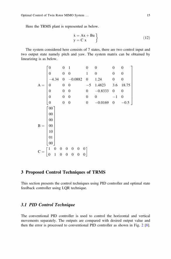
Here the TRMS plant is represented as below.
_x ¼ Axþ Buy ¼ C x
�ð12Þ
The system considered here consists of 7 states, there are two control input andtwo output state namely pitch and yaw. The system matrix can be obtained bylinearizing is as below.
A ¼
0 0 1 0 0 0 0
0 0 0 1 0 0 0
�4:34 0 �0:0882 0 1:24 0 0
0 0 0 �5 1:4823 3:6 18:75
0 0 0 0 �0:8333 0 0
0 0 0 0 0 �1 0
0 0 0 0 �0:0169 0 �0:5
2666666666664
3777777777775
B ¼
00
00
00
00
10
01
00
2666666666664
3777777777775
C ¼ 1 0 0 0 0 0 0
0 1 0 0 0 0 0
� �
3 Proposed Control Techniques of TRMS
This section presents the control techniques using PID controller and optimal statefeedback controller using LQR technique.
3.1 PID Control Technique
The conventional PID controller is used to control the horizontal and verticalmovements separately. The outputs are compared with desired output value andthen the error is processed to conventional PID controller as shown in Fig. 2 [8].
Optimal Control of Twin Rotor MIMO System … 15

Here, r(t) is the reference input, e(t) is error signal, u(t) is the control force and α(t)is the output of plant.
The controller output of conventional PID controller [9] is given as in Eq. 13
u(t) ¼ Kpe tð Þ þ Ki
Ze(t) dtþ Kd
de(t)dt
ð13Þ
where,Kp Proportional gain,Ki Integral gain,Kd Derivative gain.
3.2 Optimal Control Technique
Here the plant taken is time varying because the optimal control problem is for-mulated for the time varying system. Control input of the plant is described asshown in Fig. 3.
uðtÞ ¼ �KðtÞ xðtÞ ð14Þ
The control input here is linear and the control energy is given by uTðtÞRðtÞuðtÞ,where R(t) is the square matrix known as control cost matrix. Control energyexpression is in quadratic form because the equation contains uTðtÞRðtÞuðtÞ qua-dratic function of u(t). The transient energy can be expressed as xTðtÞQðtÞ x(t),
r(t) e(t) u(t) •(t)PID
controlTRMS+
_
Fig. 2 PID control scheme for TRMS
x.
= Ax + Bu+
_
C
K
r =0 u x y
Fig. 3 Optimal control scheme of TRMS
16 S.K. Pandey and V. Laxmi

where Q(t) is square symmetric matrix called state weighing matrix [10]. Hence theobjective function is
Jðt; tfÞ ¼Ztft
ðxTðtÞQðtÞ xðtÞ þ uTðtÞRðtÞ uðtÞÞdt ð15Þ
where t and tf are initial and final time respectively. The main objective here is tominimize the objective function as described by Eq. 15 by choosing an optimalvalue of gain matrix K(t). By considering Eqs. 12 and 14.
_xðtÞ ¼ A� BKðtÞð ÞxðtÞ ð16Þ
_xðtÞ ¼ AK xðtÞ ð17Þ
where AK ¼ A � BKðtÞð Þ is close loop state dynamics matrix. The solution ofEq. 16 is
xðtÞ ¼ hKðt; t0Þxðt0Þ ð18Þ
where hKðt; t0Þ is the state transition matrix of closed loop system, on substitutingEq. 18 in 15 the given objective function is as
Jðt; tfÞ ¼Ztft
ðxTðtÞhTK s; tð ÞðQ sð Þ þ KT sð ÞR sð ÞKðsÞÞhKðs; tÞxðtÞds ð19Þ
This can be written as
Jðt; tfÞ ¼ xTðtÞMðt; tfÞxðtÞ ð20Þ
where
Mðt; tfÞ ¼Ztft
hKðs; tÞðQðsÞ þ KTðsÞRðsÞKðsÞÞhKðs; tÞds ð21Þ
By Eqs. 18 and 19
ðt; tfÞ ¼Ztft
ðxTðsÞðQðsÞ + KTðsÞRðsÞKðsÞÞ xðsÞ ds ð22Þ
Now differentiating Eq. 22 with respect to time ‘t’
Optimal Control of Twin Rotor MIMO System … 17

@J(t; tfÞ@t
¼ �xTðt)(QðtÞ þ KTðt)RðtÞKðtÞÞxðtÞ ð23Þ
Also partially differentiating Eq. 19 with respect to time ‘t’
@J(t; tfÞ@t
¼ _x(t)T M(t; tfÞ xðtÞ þ xTðt)( @M(t; tfÞ@t
Þ xðtÞ þ xTðtÞ Mðt; tfÞ _xðtÞ ð24Þ
By combining Eqs. 17 and 24
@Jðt; tfÞ@t
¼ xTðtÞðAKðtÞMðt; tfÞ þ ð@Mðt; tfÞ@t
ÞxðtÞ þMðt; tfÞAKðtÞÞxðtÞ ð25Þ
Now considering Eqs. 23 and 25
� @Mðt; tfÞ@t
¼ AKðtÞ Mðt; tfÞ þ ATKðtÞ Mðt; tfÞ þ ðQðtÞ þ KTðtÞRðtÞKðtÞÞ ð26Þ
Above equation describe the matrix Riccati equation for finite time duration.Optimal control gain matrix K(t) is obtained by solving Eq. 26.
KðtÞ ¼ R�1ðtÞ BTðtÞM ð27Þ
By considering the closed loop system as asymptotically stable, M is a optimalmatrix, Q(t) and R(t) are positive definite matrix and positive semi definite matrixare time independent. The value of Q and R are randomly chosen and varied untilthe output of system does not get the desired value.
The control gain matrix K has been calculated here is as below.
K ¼ �0:1510 0:0044 0:0352 0:0011 �0:54 0:0024 0:0226�0:0053 1 �0:0046 1 0:0421 �0:0056 �2:0037
� �
4 Simulation Results
To implement the above control techniques, the TRMS is designed using Simulink.The responses of reference inputs of the LQR controller are presented in this sectionwhich is compared with the results of the conventional PID controller. In simulationthe transient and steady state response of the system is investigated such as over-shoot, settling time, steady state error. The reference value for step input is takenhere as 0.5 for horizontal plane and 0.2 for vertical plane. Figure 4a, b shows the
18 S.K. Pandey and V. Laxmi

response of the TRMS in horizontal and vertical plane using PID control technique.Figure 4c, d shows the response of the TRMS in horizontal and vertical plane usingoptimal control technique. Figure 5a, b shows the control effort of the TRMS inhorizontal and vertical plane using PID control technique. Figure 5c, d shows thecontrol effort of the TRMS in horizontal and vertical plane using optimal controltechnique.
Table 1 shows the physical parameters of TRMS and Table 2 depicts thecharacteristics of step response of TRMS using PID controller and optimalcontroller.
0 10 20 30 40 50 60 70 80 90 100
-1.5
-1
-0.5
0
0.5
1
1.5
time(s)
rad
referencesystem output
0 5 10 15 20 25 30-0.05
0
0.05
0.1
0.15
0.2
0.25
0.3
time(s)
rad
referencesystem output
0 10 20 30 40 50 60 70 80 90 100-0.1
00.10.20.30.40.50.60.70.80.9
time(s)
rad
referencesystem output
0 5 10 15 20 25 30 35 40 45 50-1
-0.8-0.6-0.4-0.2
00.20.40.60.8
1
time(s)
rad
referencesystem output
(a)
(b)
(c)
(d)
Fig. 4 a Step response in horizontal plane using PID control. b Step response in vertical planeusing PID control. c Step response in horizontal plane using optimal control. d Step response invertical plane using optimal control
Optimal Control of Twin Rotor MIMO System … 19

0 10 20 30 40 50 60 70 80 90 100-4
-3
-2
-1
0
1
2
3
4
time(s)
rad
0 5 10 15 20 25 30-1
-0.8-0.6-0.4-0.2
00.20.40.60.8
1
time(s)
rad
0 10 20 30 40 50 60 70 80 90 100-0.1
0
0.1
0.2
0.3
0.4
0.5
0.6
time(s)
rad
0 5 10 15 20 25 300.8
11.21.41.61.8
22.22.42.6
time(s)
rad
(a)
(b)
(c)
(d)
Fig. 5 a Control effort in vertical plane using PID control. b Control effort in horizontal planeusing PID control. c Control effort in vertical plane using optimal control. d Control effort inhorizontal plane using optimal control
Table 2 Characteristics of step response
Plane Referencevalue
Risetime (s)
Settlingtime (s)
Max.over shoot (%)
Steadystate error
PIDcontroller [8]
Horizontal 0.5 2.0 18 25.0 0.0
Vertical 0.2 6.0 14 20.0 0.0
Optimalcontroller
Horizontal 0.5 4.4 5.7 0.0 0.0
Vertical 0.2 5.0 8.0 8.0 0.0
20 S.K. Pandey and V. Laxmi

5 Conclusion
In this paper, the TRMS with two degrees of freedom was considered. Themathematical modeling of TRMS has been done in MATLAB/SIMULINK. HerePID and optimal controllers has been designed to control the horizontal and verticalmovements of the system. The performance of the designed controllers has beenevaluated with step input. The results show that the optimal controller gives betterperformance in terms of both transient and steady state response as compared to thePID controller. The control effort in case of optimal controller is minimum then thePID controller.
References
1. TRMS 33-949S User Manual, Feedback instruments Ltd., East Sussex, U.K. (1998)2. Ahmad, S.M., Chipperfield, A.J., Tokhi, M.O.: Dynamic modeling and open loop control of
twin rotor multi input multi output system. J. Syst. Control Eng. (2002)3. Wen, P., Li, Y.: Twin rotor system modeling, de-coupling and optimal control. Proceedings of
the IEEE International Conference on Mechatronics and Automation, Beijing, China (2011)4. Lu, T.W., Wen, P.: Time optimal and robust control of twin rotor system. In: IEEE
International Conference on Control and Automation Guangzhou, China (2007)5. Pratap, B., Purwar, S.: Sliding mode state observer for 2-DOF twin rotor MIMO system. In:
International Conference on Power, Control and Embedded Systems, India (2010)6. Ahmad, S.M., Chipperfield, A.J., Tokhi, M.O.: Dynamic modelling and optimal control of a
twin rotor MIMO system. In: Proceedings of IEEE national aerospace and electronicsconference (NAECON’2000), pp. 391–398, Dayton, Ohio, USA (2000)
7. Bennoune, A., Kaddouri, A., Ghribi, M.: Application of the dynamic linearization technique tothe reduction of the energy consumption of induction motors. Appl. Math. Sci. 1, 1685–1694(2007)
8. Pandey, S.K., Laxmi, V.: Control of twin rotor MIMO system using PID controller withderivative filter coefficient. In: Proceedings of IEEE Student’s Conference on Electrical,Electronics and Computer Science, MANIT Bhopal, India (2014)
9. Ramalakshmi, A.P.S., Manoharan, P.S.: Nonlinear modeling and control of twin rotor MIMOsystem. In: Proceedings of IEEE International Conference on Advanced CommunicationControl and Computing Technologies (ICACCCT), pp. 366–369, Ramanathapuram, India(2012)
10. Saini, S.C., Sharma, Y., Bhandari, M., Satija, U.: Comparison of pole placement and LQRapplied to single link flexible manipulator. In: International Conference on CommunicationSystems and Network Technologies (2012)
Optimal Control of Twin Rotor MIMO System … 21

http://www.springer.com/978-81-322-2204-0


![Decoupled Integral LQR Controller with Anti-windup ...jestec.taylors.edu.my/Vol 14 issue 3 June 2019/14_3_20.pdf · decoupling control [1]. The interaction in a MIMO system makes](https://static.fdocuments.in/doc/165x107/5e6b5f9434160e64ed220e72/decoupled-integral-lqr-controller-with-anti-windup-14-issue-3-june-201914320pdf.jpg)


