
OptiFlo RC - · PDF file©2015 American Air Filter Company, Inc. Any use of the text or...
38
© 2015 American Air Filter Company, Inc. Any use of the text or images this document contains, without permission of American Air Filter Company, Inc., is prohibited. OptiFlo, AAF, REDClean, REDFiltration, and Reliable Efficient Durable are registered trademarks of American Air Filter Company, Inc. d/b/a AAF International. GDED-IOM-215- OptiFlo ® RC
Transcript of OptiFlo RC - · PDF file©2015 American Air Filter Company, Inc. Any use of the text or...

© 2015 American Air Filter Company, Inc. Any use of the text or images
this document contains, without permission of American Air FilterCompany, Inc., is prohibited. OptiFlo, AAF, REDClean, REDFiltration, andReliable Efficient Durable are registered trademarks of American AirFilter Company, Inc. d/b/a AAF International.
GDED-IOM-215-
OptiFlo® RC
© 2015 American Air Filter Company, Inc. Any use of the text or images
this document contains, without permission of American Air FilterCompany, Inc., is prohibited. OptiFlo, AAF, REDClean, REDFiltration, andReliable Efficient Durable are registered trademarks of American Air FilterCompany, Inc. d/b/a AAF International.
GDED-IOM-215-
OptiFlo RC IOM V01
TO ORDER SPARE & REPLACEMENT PARTS
Call 1-800-477-1214Email: [email protected]
Parts SalesPower & IndustrialAAF International
9920 Corporate Campus DriveSuite 2200
Louisville, KY 40223-5000USA
Internet: http://www.AAFParts.com

3
© 2015 American Air Filter Company, Inc. Any use of the text or
images this document contains, without permission of American AirFilter Company, Inc., is prohibited. OptiFlo, AAF, REDClean,REDFiltration, and Reliable Efficient Durable are registered trademarksof American Air Filter Company, Inc. d/b/a AAF International. GDED-IOM-215-
TABLE OF CONTENTS
1 INTRODUCTION........................................................................................................................... 5
2 SAFETY.............................................................................................................................................. 5
2.1 Safety statement ................................................................................................................. 52.2 Safe working practices and staff training ............................................................ 62.3 Dust explosions .................................................................................................................... 62.4 Electrical hazards ................................................................................................................ 82.5 Rotating Equipment ........................................................................................................... 82.6 Safety Guards ........................................................................................................................ 8
3 GENERAL PRODUCT INFORMATION ................................................................................ 9
3.1 Description .............................................................................................................................. 93.2 Purpose and intended use ............................................................................................. 93.3 Normal Operation................................................................................................................ 93.4 Sizes .......................................................................................................................................... 103.5 Filter elements .................................................................................................................... 113.6 Weights ................................................................................................................................... 12
4 PRODUCT SHIPMENT .............................................................................................................. 13
4.1 How the product ships ................................................................................................... 134.2 Items that ship separately .......................................................................................... 13
5 PRODUCT RECEIPT AT THE DESIGNATED DELIVERY POINT .......................... 13
5.1 Responsibilities of the customer or customer’s agent ............................... 135.2 Receiving................................................................................................................................ 135.3 Inspection on arrival....................................................................................................... 135.4 Damaged goods.................................................................................................................. 135.5 Missing goods ...................................................................................................................... 14
6 UNLOADING AND HANDLING ............................................................................................ 14
6.1 Unloading and lifting into position ......................................................................... 14
7 STORAGE AND PROTECTION.............................................................................................. 15
8 SITE PREPARATION ................................................................................................................ 15
8.1 Locating equipment ......................................................................................................... 158.2 Foundations .......................................................................................................................... 158.3 Anchoring............................................................................................................................... 15
9 ASSEMBLY AND INSTALLATION ...................................................................................... 16
4
© 2015 American Air Filter Company, Inc. Any use of the text or
images this document contains, without permission of American AirFilter Company, Inc., is prohibited. OptiFlo, AAF, REDClean,REDFiltration, and Reliable Efficient Durable are registered trademarksof American Air Filter Company, Inc. d/b/a AAF International. GDED-IOM-215-
9.1 Introduction ......................................................................................................................... 169.2 Assembling and installing the structure ............................................................. 16
9.2.1 Modular assembly ..............................................................................................................................................169.2.2 Flanged joints ........................................................................................................................................................169.2.3 Products shipped as a single assembly. ...........................................................................................179.2.4 Products shipped in multiple modular assemblies ...................................................................179.2.5 Installing the access components .........................................................................................................189.2.6 Installation of control panel .......................................................................................................................189.2.7 Installation of the cartridge filter elements ...................................................................................199.2.8 Installation of accessories ...........................................................................................................................219.2.9 Electrical connections ......................................................................................................................................219.2.10 Compressed air connections .................................................................................................................239.2.11 Ductwork Installation .................................................................................................................................23
10 EXPLOSION VENTS .................................................................................................................. 24
10.1 Installation of the explosion vent ........................................................................... 2410.2 Assembly ................................................................................................................................ 2410.3 Explosion Vent Burst Sensor ...................................................................................... 2510.4 Servicing................................................................................................................................. 2610.5 Safety distance ................................................................................................................... 26
11 START-UP & OPERATION ..................................................................................................... 26
11.1 Start-up checklist.............................................................................................................. 2611.2 Normal operation .............................................................................................................. 27
12 RECOMMENDED MAINTENANCE ....................................................................................... 28
12.1 Record Keeping .................................................................................................................. 2812.2 Initial Weekly Maintenance ........................................................................................ 2812.3 Six months ............................................................................................................................ 2912.4 Annual Maintenance ........................................................................................................ 3012.5 Cartridge removal and installation ......................................................................... 3012.6 Accessories ........................................................................................................................... 32
13 TROUBLESHOOTING................................................................................................................ 33
13.1 High differential pressure ............................................................................................ 3313.2 Visible Discharge (emission to atmosphere) ................................................... 3413.3 Insufficient Extraction ................................................................................................... 3513.4 Other Problems .................................................................................................................. 35
14 RECOMMENDED SPARE PARTS LIST .............................................................................. 36
5
© 2015 American Air Filter Company, Inc. Any use of the text or
images this document contains, without permission of American AirFilter Company, Inc., is prohibited. OptiFlo, AAF, REDClean,REDFiltration, and Reliable Efficient Durable are registered trademarksof American Air Filter Company, Inc. d/b/a AAF International. GDED-IOM-215-
1 INTRODUCTIONThis document contains the information necessary to properly receive,
assemble, install, operate, and maintain the AAF® OptiFlo® RC filter system andfilters. The purchaser, installer, and operator of the filter system MUST read andcomply with this document in its entirety prior to installation of the equipment andits operation. Failure to comply with the requirements of this manual may void theproduct warranty. The information and guidelines contained in this manual are notexhaustive, and additional or different precautions, measures, training, etc. maybe needed depending on the specific circumstances.
CAUTIONThese instructions are specific to the AAF OptiFlo RC filter system and filters.All ancillary tasks including, but not limited to, electrical and mechanicalwork, equipment handling, and safety procedures must be performed inaccordance with industry accepted practice and all relevant local, state, andfederal government codes, laws, and policies.
2 SAFETY2.1 Safety statement
The air cleaning equipment supplied by AAF International ranges from verylarge multiple-component assemblies which require significant and complex,rigging, handling and assembly on-site, to small compact assemblies that areeasily handled and maneuvered. In addition to size, many of the dust collectorswill require electrical connections, compressed air connections, and will featurehigh speed rotating equipment.
At all times, when dealing with industrial equipment such as dust collectionequipment personnel safety must be the highest priority of all involved, fromriggers, installers, operators, users, and maintenance personnel. Thoseresponsible on-site shall review the details of the equipment beforehand anddevelop a plan for dealing with all stages of the installation from receipt of theequipment on-site to start-up, commissioning, and hand-over. All applicablehealth, safety, and environmental (“HSE”) rules, regulations, and legislation shallbe fully complied with at all times.

6
© 2015 American Air Filter Company, Inc. Any use of the text or
images this document contains, without permission of American AirFilter Company, Inc., is prohibited. OptiFlo, AAF, REDClean,REDFiltration, and Reliable Efficient Durable are registered trademarksof American Air Filter Company, Inc. d/b/a AAF International. GDED-IOM-215-
2.2 Safe working practices and staff trainingAAF International is fully committed to the safety of its employees and those
of its customers. In this spirit, the following guidelines are offered for theconsideration of those responsible:
All personnel shall receive safety training specific to the site, the task, andthe conditions under which the work will be conducted.
All personnel shall be equipped with appropriate PPE (personal protectiveequipment) such as clothing, footwear, hard-hats, gloves, ear protection, eyeprotection, and safety harness.
All personnel involved in any stage of the process shall have been trained forthe tasks in which they will be involved and at all times shall be under the directsupervision of experienced supervisors and managers.
All personnel shall be equipped with appropriate tools and equipment tosafely and efficiently complete their task.
Adequate lighting shall be supplied at all times while work is beingconducted.
A work perimeter shall be set up to define the limits of the area within whichthe work will be conducted and outside which there will be no threat to the safetyof personnel or plant. The perimeter shall be taped-off and marked appropriatelyto prevent accidental ingress of uninvolved personnel or equipment. When thework area impedes into existing access ways or traffic routes for which no practicalalternative is available, barriers, wardens and flaggers shall be employed to safelycontrol crossing traffic and personnel.
At any time only those personnel directly involved in completing the task athand shall be allowed within the work perimeter.
2.3 Dust explosionsDust explosions constitute a serious industrial hazard and may result in
death, serious injury, and/or devastating property damage. It is the responsibilityof the user to identify the nature of the dust and whether or not it poses an
7
© 2015 American Air Filter Company, Inc. Any use of the text or
images this document contains, without permission of American AirFilter Company, Inc., is prohibited. OptiFlo, AAF, REDClean,REDFiltration, and Reliable Efficient Durable are registered trademarksof American Air Filter Company, Inc. d/b/a AAF International. GDED-IOM-215-
explosive hazard and to properly mitigate this hazard. Except as otherwiseexpressly provided in writing, AAF makes no representation or warranty inconnection with explosion hazard equipment, including, but not limited to, thenecessity or effectiveness of explosion hazard equipment or to the design,installation, operation, and performance of such equipment. The basic standard fordealing with explosive dust applications is the National Fire Protection Agency(“NFPA”), NFPA 69: Standard on Explosion Prevention Systems. This standardapplies to the design, installation, operation, maintenance, and testing of systemsfor the prevention of explosions by means of various methods. The user shall befully conversant with the provisions of NFPA and shall comply in full with all of itsrequirements.
By its very nature AAF equipment is intended to be used to capture airborneparticulate matter, otherwise known as dust. There are various methods fordealing with a dust explosion in a dust collector. These can include, but are notlimited to, the use of properly designed explosion vents, explosion suppressionsystems, or flameless vents. The user shall understand which method is beingused and who is responsible for the design and supply of the equipment required.When an explosive dust has been properly identified to AAF, the dust collector maybe structurally designed to withstand the internal pressure generated during theexplosive event and fitted with an explosion vent, or with multiple vents, designedto safely discharge the pressure and the resulting fireball. The user shall reviewthe purchase order and the documents referenced within it to determine ifexplosion protection equipment has been supplied by AAF International. Wherethis is the case, review the appropriate sections of this manual that deal with theinstallation, operation and maintenance of the equipment ordered.
When explosion protection systems are supplied by multiple vendors, it isthe responsibility of the user to coordinate between suppliers to ensure that theequipment supplied by each vendor will work together to achieve the requiredprotection. For instance, if an explosion suppression system is being supplied byparties other than AAF, it is incumbent on the user to ensure that the dustcollection equipment has been ordered to resist the internal pressure defined bythe suppression equipment supplier.
Dust collectors fitted with explosion vents must not be located indoors,unless properly designed in accordance to NFPA regulations. The equipment shall
8
© 2015 American Air Filter Company, Inc. Any use of the text or
images this document contains, without permission of American AirFilter Company, Inc., is prohibited. OptiFlo, AAF, REDClean,REDFiltration, and Reliable Efficient Durable are registered trademarksof American Air Filter Company, Inc. d/b/a AAF International. GDED-IOM-215-
be oriented so that the vent will discharge to an unoccupied zone. Such a zone willbe prohibited to personnel and shall not include critical equipment or services suchas fuel storage tanks, flammable materials, fire hydrants, power distribution orelectrical control equipment, or similar. If the vent(s) is/are located on the side(s)of the equipment the vent discharge area shall be isolated with barriers erected toprevent the parking of vehicles, pedestrian use, use of the area for temporarystorage, etc. Warning signs shall be posted. Include diagrams showing thedistribution of a typical dust explosion discharge.
2.4 Electrical hazardsBefore doing any work on the AAF equipment make sure that all potential
electrical hazards have been identified and that all electric current connected tothe equipment, and to any connected or associated equipment, has been properlydisconnected and securely locked-out to prevent accidental reconnection prior tocompletion of the work. All electrical work shall be done in full accordance with thecurrent edition NFPA 70, the National Electrical Code, and all other applicable laws,rules, and regulations. All electrical work shall be performed by a licensedelectrician. Only original AAF parts shall be used as replacements for ongoingmaintenance and repair.
2.5 Rotating EquipmentThe OptiFlo RC can include a fan which is installed with the dust collector. The
fan wheel rotates and has the potential to cause severe injury. The fan wheelcould be accessed from outside the housing through the fan discharge. All duecare should be exercised to avoid any contact with the operating fan. Under nocircumstances should the fan ever be allowed to operate when any of the accesspanels on the dust collector, or the silencer, have been removed. The fan must bedisconnected and locked out prior to the performance of any maintenance work,see paragraph 2.4.
2.6 Safety GuardsThe dust collector cabinet prevents access to the fan inlet. All access panels
shall remain bolted in place while the fan is operating. Prior to the removal of anyaccess panels, the electrical power to the collector shall be disconnected andlocked out, see paragraphs 2.4 and 2.5. After electrical power is disconnected, thefan wheel will continue to rotate for a period of time before coasting to a stop. Donot access the fan until the fan wheel has come to a complete stop.
9
© 2015 American Air Filter Company, Inc. Any use of the text or
images this document contains, without permission of American AirFilter Company, Inc., is prohibited. OptiFlo, AAF, REDClean,REDFiltration, and Reliable Efficient Durable are registered trademarksof American Air Filter Company, Inc. d/b/a AAF International. GDED-IOM-215-
3 GENERAL PRODUCT INFORMATION3.1 Description
The OptiFlo RC is a complete pulse-jet cartridge collector system capable ofproviding continuous on-line cleaning. This cartridge collector utilizes highefficiency pleated filter elements arranged in a horizontal arrangement. Dust ladenair enters above the filter elements and moves in a true down flow directionbetween the filters. The airstream passes through the media as the dust iscollected on the filter media. The clean air then moves through the tube sheetsection and into a clean air plenum at the rear of the module.
3.2 Purpose and intended useThe OptiFlo RC is intended to be used for relatively dry nuisance dusts, with
loadings generally less than 3 grains per cubic foot (7 g/m3). Typical applicationsan OptiFlo RC is used for include weld fume, laser tables, thermal spray, chemical,pharmaceutical, and food processing. The cartridge that is used in the OptiFlo RCshould be suitable for the intended application.
The REDClean® N cartridge is suitable for most applications where theOptiFlo RC is used. Contact AAF International for assistance on a cartridge designfor your application. It is recommended that you use only AAF Internationalcartridges on AAF International equipment.
3.3 Normal OperationDuring normal operation, air enters the OptiFlo dust collector through the
high inlet and moves downward through the dirty air plenum, in true “downflow”fashion. The cleaned air passes through the filter elements, while dust is collectedon the outside surfaces of the elements. Clean air flows through the center of theelements into the clean air plenum, where it exits through the clean air outlet.
During filter element cleaning, a pulse controller automatically selects theelement or pair of elements to be cleaned, activating solenoid valves which openair diaphragm valves. High pressure air pulses directly into the center of theselected element, or pair of elements, for 100 milliseconds, blowing collected dustoff the filter element(s). The dust is swept downward into the hopper by theprevailing airflow and gravity.
10
© 2015 American Air Filter Company, Inc. Any use of the text or
images this document contains, without permission of American AirFilter Company, Inc., is prohibited. OptiFlo, AAF, REDClean,REDFiltration, and Reliable Efficient Durable are registered trademarksof American Air Filter Company, Inc. d/b/a AAF International. GDED-IOM-215-
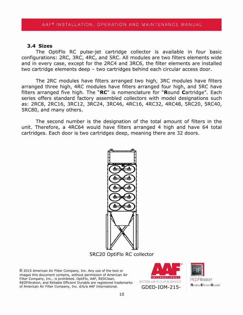
3.4 SizesThe OptiFlo RC pulse-jet cartridge collector is available in four basic
configurations: 2RC, 3RC, 4RC, and 5RC. All modules are two filters elements wideand in every case, except for the 2RC4 and 3RC6, the filter elements are installedtwo cartridge elements deep – two cartridges behind each circular access door.
The 2RC modules have filters arranged two high, 3RC modules have filtersarranged three high, 4RC modules have filters arranged four high, and 5RC havefilters arranged five high. The “RC” is nomenclature for “Round Cartridge”. Eachseries offers standard factory assembled collectors with model designations suchas: 2RC8, 2RC16, 3RC12, 3RC24, 3RC46, 4RC16, 4RC32, 4RC48, 5RC20, 5RC40,5RC80, and many others.
The second number is the designation of the total amount of filters in theunit. Therefore, a 4RC64 would have filters arranged 4 high and have 64 totalcartridges. Each door is two cartridges deep, meaning there are 32 doors.
5RC20 OptiFlo RC collector

11
© 2015 American Air Filter Company, Inc. Any use of the text or
images this document contains, without permission of American AirFilter Company, Inc., is prohibited. OptiFlo, AAF, REDClean,REDFiltration, and Reliable Efficient Durable are registered trademarksof American Air Filter Company, Inc. d/b/a AAF International. GDED-IOM-215-
3.5 Filter elementsThe OptiFlo RC utilizes cartridges with pleated media for dust collection. For
optimal performance, the OptiFlo RC is fitted with REDClean® N media as thestandard cartridge. The REDClean N cartridge is suitable for most applicationswhere the OptiFlo RC is used. Contact AAF International for assistance on acartridge design for your application. To ensure proper operation, it isrecommended that you use only AAF International cartridges on AAF Internationalequipment.
Typical REDClean N cartridge for the OptiFlo RC
12
© 2015 American Air Filter Company, Inc. Any use of the text or
images this document contains, without permission of American AirFilter Company, Inc., is prohibited. OptiFlo, AAF, REDClean,REDFiltration, and Reliable Efficient Durable are registered trademarksof American Air Filter Company, Inc. d/b/a AAF International. GDED-IOM-215-
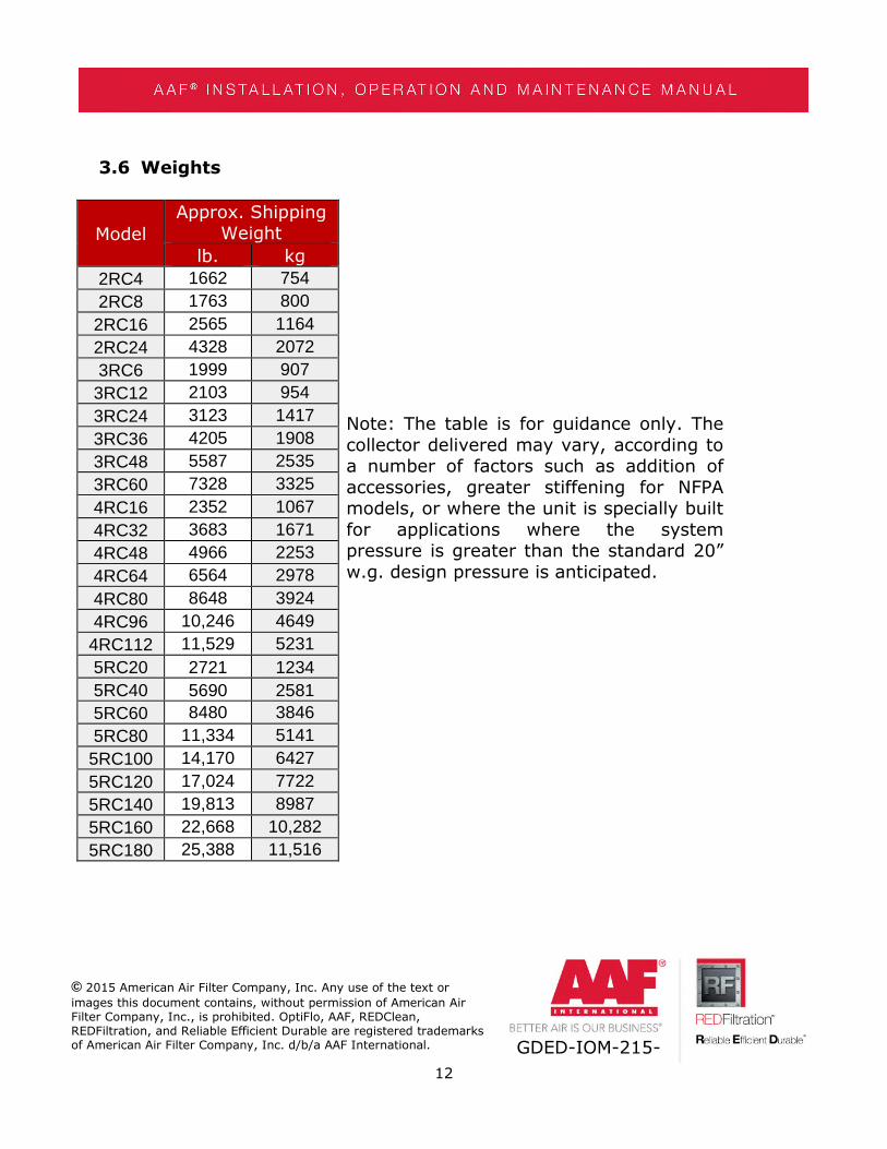
3.6 Weights
Model
Approx. ShippingWeight
Note: The table is for guidance only. Thecollector delivered may vary, according toa number of factors such as addition ofaccessories, greater stiffening for NFPAmodels, or where the unit is specially builtfor applications where the systempressure is greater than the standard 20”w.g. design pressure is anticipated.
lb. kg
2RC4 1662 754
2RC8 1763 800
2RC16 2565 1164
2RC24 4328 2072
3RC6 1999 907
3RC12 2103 954
3RC24 3123 1417
3RC36 4205 1908
3RC48 5587 2535
3RC60 7328 3325
4RC16 2352 1067
4RC32 3683 1671
4RC48 4966 2253
4RC64 6564 2978
4RC80 8648 3924
4RC96 10,246 4649
4RC112 11,529 5231
5RC20 2721 1234
5RC40 5690 2581
5RC60 8480 3846
5RC80 11,334 5141
5RC100 14,170 6427
5RC120 17,024 7722
5RC140 19,813 8987
5RC160 22,668 10,282
5RC180 25,388 11,516
13
© 2015 American Air Filter Company, Inc. Any use of the text or
images this document contains, without permission of American AirFilter Company, Inc., is prohibited. OptiFlo, AAF, REDClean,REDFiltration, and Reliable Efficient Durable are registered trademarksof American Air Filter Company, Inc. d/b/a AAF International. GDED-IOM-215-
4 PRODUCT SHIPMENT4.1 How the product ships
The OptiFlo RC collectors are shipped with the filter elements installed. Unitsshipped as 4 or greater assembled modules are not skidded. The OptiFlo RC isusually shipped by truck or flat bed. Specific shipping information will be given tothe customer for their specific collector at the time of shipment.
4.2 Items that ship separatelyTo save the customer money, AAF International may ship items separately.
The customer will be notified which equipment ships separately when the order isplaced. Items that ship separately should be set aside in an area that is clean, dry,and in a place where damage to the equipment will not occur.
5 PRODUCT RECEIPT AT THE DESIGNATED DELIVERY POINT5.1 Responsibilities of the customer or customer’s agent
Ensure all loading/unloading equipment and safety equipment is on site atthe time of delivery. Safe and efficient operation of the collector depends onproper installation. Know proper laws, codes and regulations before installationstarts.
5.2 ReceivingRemove crates, tarps, shipping straps, etc. along with any loose items or
equipment before unloading the OptiFlo RC.
5.3 Inspection on arrivalThe OptiFlo RC is normally shipped by truck and should be checked for
damage that may have occurred en route. Compare the collector(s) received tothe description and/or drawing of the collector(s) ordered. Immediately report anydifferences or missing items from the order to AAF International. Remove looseitems or components before lifting the collector from the truck.
A qualified installation and service company should complete installation ofthe collector and accessories.
5.4 Damaged goodsIf there is any visible damage to the packaging or the equipment notify the
carrier and AAF before proceeding further and, if appropriate, file an immediate
14
© 2015 American Air Filter Company, Inc. Any use of the text or
images this document contains, without permission of American AirFilter Company, Inc., is prohibited. OptiFlo, AAF, REDClean,REDFiltration, and Reliable Efficient Durable are registered trademarksof American Air Filter Company, Inc. d/b/a AAF International. GDED-IOM-215-
claim with the carrier against such damage. Be aware that damage to packagingmay indicate hidden damage to the product that is not immediately discernable.
Digital color photographs must be taken of any damage to the packagingand the equipment immediately on discovery. The nature of any damage mustalso be documented in writing. Adequate documentation will be critical to supportany claims.
Contact AAF International for claim filing procedure.
5.5 Missing goodsAny missing goods should be noted on the delivery receipt, and the carrier
and AAF notified immediately. Contact AAF International for claim filing procedure.
FOR ASSISTANCE: Contact AAF International at 1-800-477-1214. Have theAAF control number available. The control number can be found on theshipping papers.
6 UNLOADING AND HANDLING6.1 Unloading and lifting into position
Failure to lift the collector correctly can result in severe personal injury,property damage, or even death.
Connect lifting sling to all supplied lifting lugs, distributing the load evenly.Always use spreader bars on collectors field assembled wider than 4 modules.
Use clevises, not hooks, on lifting sling.
Use of spreader bars is recommended on all lifting slings.
Check the drawings of the specific OptiFlo RC ordered for dimensions andweights to ensure proper lifting and installation equipment.
All lifting operations must be made in compliance with the relevant HSElegislation.

15
© 2015 American Air Filter Company, Inc. Any use of the text or
images this document contains, without permission of American AirFilter Company, Inc., is prohibited. OptiFlo, AAF, REDClean,REDFiltration, and Reliable Efficient Durable are registered trademarksof American Air Filter Company, Inc. d/b/a AAF International. GDED-IOM-215-
7 STORAGE AND PROTECTIONIn the event the OptiFlo RC is not placed in service within 30 days after
receipt, the filter cartridges must be removed and stored in a clean, dry place toprevent possible moisture accumulation in the media.
8 SITE PREPARATION8.1 Locating equipment
The dust collector site location must take into account the wind and seismicloadings. See collector specifications to ensure proper site location.
The collector is suitable for indoor and outdoor applications. Ensure properequipment and accessories are equipped on the OptiFlo RC for such installations.The collector can be located on a foundation (by others) or on structural framing(by others).
Ensure local laws, codes and regulations are followed for the materials beingcollected. Noise levels should be considered when selecting the proper location ofthe OptiFlo RC.
Locate the OptiFlo RC in a location so that maintenance to the collector canbe handled easily. See collector drawing for cartridge clearance.
In the case of hazardous dust, consult your local authorities, laws, codes, orregulations for the location of the unit.
8.2 FoundationsThe OptiFlo RC dust collector is usually mounted on a reinforced concrete
foundation. However, roof mounting is also possible. When calculating forfoundation or roof mounting, the weight of the dust collector, material collected,and all auxiliary equipment must be considered together with snow, wind, andseismic loads. Check the drawings of the specific OptiFlo RC ordered for the dustcollector weight.
8.3 AnchoringSee the specific OptiFlo RC collector drawing for anchor bolt location. Anchor
bolts must extend at least 1.75 inches above the foundation. The collector should
16
© 2015 American Air Filter Company, Inc. Any use of the text or
images this document contains, without permission of American AirFilter Company, Inc., is prohibited. OptiFlo, AAF, REDClean,REDFiltration, and Reliable Efficient Durable are registered trademarksof American Air Filter Company, Inc. d/b/a AAF International. GDED-IOM-215-
be located with consideration for emptying hoppers, electrical and air connectionsand maintenance, and should have the shortest run of ductwork possible.
9 ASSEMBLY AND INSTALLATION9.1 Introduction
Safe and efficient operation of the OptiFlo RC depends on proper installation.
AAF recommends that the ductwork going into the collector be as straight aspossible, with at least 5 diameters of straight run recommended.
Authorities with jurisdiction should be consulted before installing the OptiFloRC to ensure local installation laws, codes, regulations and procedures arefollowed.
A qualified installation and service agent must complete installation andservice of the dust collector and equipment.
Ensure all covers from shipping and loose materials are removed from thecollector before installation. Failure to do so can result in failure of the dustcollector.
Ensure the hardware, on the dust collector assemblies, is properly installedand tight before installation.
9.2 Assembling and installing the structure9.2.1 Modular assembly
OptiFlo RC units with multiple modules normally have their housings factorypre-assembled up to a minimum of 4 modules, with legs and hoppers sent for siteassembly. If more than 4 modules are required or if there are site access problemsthat preclude delivery of very large assemblies, it may be necessary to jointogether on site the housing modules. In this case the modules to be joined willnot have side panels. See also 9.2.4.
9.2.2 Flanged jointsFlanged joints exist where housing modules must be bolted together and
where hoppers are bolted to the lower faces of the housing. In most cases, AAFwill provide sufficient tubes of sealant which must be applied to one of the
17
© 2015 American Air Filter Company, Inc. Any use of the text or
images this document contains, without permission of American AirFilter Company, Inc., is prohibited. OptiFlo, AAF, REDClean,REDFiltration, and Reliable Efficient Durable are registered trademarksof American Air Filter Company, Inc. d/b/a AAF International. GDED-IOM-215-
opposing faces just prior to the faces being brought together. When applyingsealant be careful to circle each bolt hole with the sealant. See also 9.2.4
9.2.3 Products shipped as a single assembly.Some of the smaller sized units may be shipped each as a single assembly
on a flat-bed truck. Careful lifting, using the supplied lifting lugs, is required toturn the unit to the vertical position prior to lowering the unit onto the legs andthe pre-prepared foundation.
9.2.4 Products shipped in multiple modular assembliesWhere product is shipped with the main housings in multiple modular
assemblies, with the hoppers and legs separate, proceed as follows:
Follow item 9.2.4.1 to pre-install the legs and then bring in the housingmodules in turn bolting the first to its legs before bringing in the second.
Pre-apply the sealant to the flanges as 9.2.2 and then bolt the housingstogether.
Install all the supplied bolts between housings loosely at first. Access to thebolt holes is gained via the porthole covers and the inlet/outlet openings (removethe covers and cartridges). When all the bolts are loosely in position they must betightened in a sequence working from the center bolts towards the corners,radiating outwards in opposite side in sequence so that the four corner bolts arelast to be tightened. This pulls the modules together with all the mating flangesflat against each other with no bulges.
9.2.4.1 Leg structureAssemble the leg structure onto the prepared foundations or steelwork using
the supplied GA drawing which shows the position of all the legs and cross braces.Ensure all the nuts and bolts are tightened and the structure is mechanically soundand secure, and level before proceeding to the next stage.
Anchors (supplied by others) must comply with local code requirements andmust be capable of supporting dead, live, wind, seismic, and other applicable loadsfor the area the dust collector is going to be installed.
18
© 2015 American Air Filter Company, Inc. Any use of the text or
images this document contains, without permission of American AirFilter Company, Inc., is prohibited. OptiFlo, AAF, REDClean,REDFiltration, and Reliable Efficient Durable are registered trademarksof American Air Filter Company, Inc. d/b/a AAF International. GDED-IOM-215-
Consult with a qualified engineer for foundation and anchoring design.
9.2.4.2 HoppersPosition the hopper(s) onto the leg structure and fix it into position using the
GA drawing as a guide. Level the hopper once installed.
9.2.4.3 Collector HousingApply sealant (supplied by AAF) to the upper flanges of the hopper(s)
ensuring the sealant circles around each bolt hole.
Lift the housing module(s) using its lifting lugs and lower into position ontothe hoppers so that the holes in the matching flanges correctly align.
CAUTION: Never stand or work beneath a suspended load.
Make certain that the housing is safely positioned onto thehoppers/supporting steel structure and that it cannot possibly fall should there bea failure of the lifting supports.
Secure the housing to the hopper with the bolts and washers that aresupplied.
All the bolts must be tightened. The lifting equipment can now be removed.
NOTE: Check all access panels on the OptiFlo RC, including the top inletpanel, front inlet panel, and the side outlets, to ensure these are caulked. If theseare not caulked and bolted, these could be leak points for the collector.
9.2.5 Installing the access componentsWhen access components, such as an access platform, are ordered with the
OptiFlo RC, separate installation instructions will be provided with the collector.
9.2.6 Installation of control panelRefer to the electrical drawings issued with the general arrangement
drawing.
19
© 2015 American Air Filter Company, Inc. Any use of the text or
images this document contains, without permission of American AirFilter Company, Inc., is prohibited. OptiFlo, AAF, REDClean,REDFiltration, and Reliable Efficient Durable are registered trademarksof American Air Filter Company, Inc. d/b/a AAF International. GDED-IOM-215-
When the AAF Control Center or Pressure Demand controller is to be used,select a location for fixing the enclosure within 15ft of the static taps located oneither of the OptiFlo RC side panels. Usually the Pressure Demand controller isfixed to the leg structure but it can be remotely located if desired.
Once the pulse controller is fixed in position, connect two parallel lines ofplastic tubing to the 2 connection taps on the pulse controller and the other endsto the static taps located on the side wall of the OptiFlo RC. These plastic pipesallow the pulse controller to measure and display the differential pressure thatexists between the clean air plenum and dirty side plenum. In some modes ofoperation, this differential pressure is used to control the pulsing.
Connect the high pressure port to the dirty side of the collector and connectthe low pressure port to the clean air side (back of the unit). Both ports arelocated on the side of the collector.
See the separate pulse controller manual for a full explanation of its featuresand modes of operation.
9.2.7 Installation of the cartridge filter elementsThe cartridges supplied with new equipment are in most circumstances
factory pre-installed by AAF. If the cartridges have been shipped separately, oruninstalled, then proceed as follows:
1. Provide safe access to the porthole doors at the front of the OptiFlo RC.
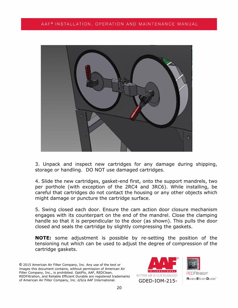
2. Open the porthole covers by lifting the red cam action handle to releasethe internal door fastening and swing open the door on its supporting hinge.
20
© 2015 American Air Filter Company, Inc. Any use of the text or
images this document contains, without permission of American AirFilter Company, Inc., is prohibited. OptiFlo, AAF, REDClean,REDFiltration, and Reliable Efficient Durable are registered trademarksof American Air Filter Company, Inc. d/b/a AAF International. GDED-IOM-215-
3. Unpack and inspect new cartridges for any damage during shipping,storage or handling. DO NOT use damaged cartridges.
4. Slide the new cartridges, gasket-end first, onto the support mandrels, twoper porthole (with exception of the 2RC4 and 3RC6). While installing, becareful that cartridges do not contact the housing or any other objects whichmight damage or puncture the cartridge surface.
5. Swing closed each door. Ensure the cam action door closure mechanismengages with its counterpart on the end of the mandrel. Close the clampinghandle so that it is perpendicular to the door (as shown). This pulls the doorclosed and seals the cartridge by slightly compressing the gaskets.
NOTE: some adjustment is possible by re-setting the position of thetensioning nut which can be used to adjust the degree of compression of thecartridge gaskets.

21
© 2015 American Air Filter Company, Inc. Any use of the text or
images this document contains, without permission of American AirFilter Company, Inc., is prohibited. OptiFlo, AAF, REDClean,REDFiltration, and Reliable Efficient Durable are registered trademarksof American Air Filter Company, Inc. d/b/a AAF International. GDED-IOM-215-
9.2.8 Installation of accessoriesWhen accessories, such as sprinklers, abrasion resistant inlets, and airlocks,
are ordered with the OptiFlo RC, separate installation instructions will be providedwith the collector. For complete information, see the most current installationdrawing or separate IOM.
9.2.9 Electrical connectionsWARNING: Potential shock hazard. Disconnect power before servicing. Only
qualified electrical personnel should work on this system.
The OptiFlo RC pulse-jet cartridge collector is supplied with electricalsolenoids in a NEMA 4 enclosure and the standard pulse controller in a NEMA4Xenclosure. Higher NEMA ratings are available as an option. Do not install inclassified hazardous locations without an enclosure suitably rated for theapplication and location.
The standard pulse control supplied with the OptiFlo RC is the DCT-1010 (or1022) Dust Collector Timer Controller. This pulse controller is used for on-demandor continuous cleaning applications.
22
© 2015 American Air Filter Company, Inc. Any use of the text or
images this document contains, without permission of American AirFilter Company, Inc., is prohibited. OptiFlo, AAF, REDClean,REDFiltration, and Reliable Efficient Durable are registered trademarksof American Air Filter Company, Inc. d/b/a AAF International. GDED-IOM-215-
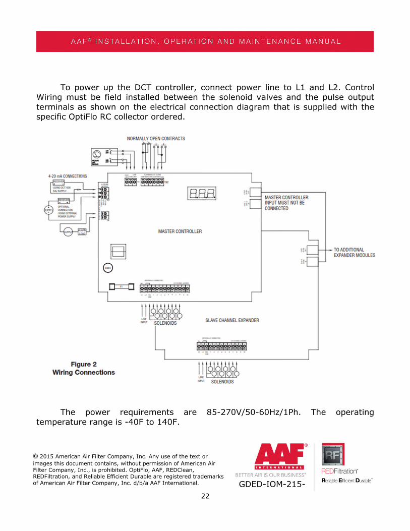
To power up the DCT controller, connect power line to L1 and L2. ControlWiring must be field installed between the solenoid valves and the pulse outputterminals as shown on the electrical connection diagram that is supplied with thespecific OptiFlo RC collector ordered.
The power requirements are 85-270V/50-60Hz/1Ph. The operatingtemperature range is -40F to 140F.
23
© 2015 American Air Filter Company, Inc. Any use of the text or
images this document contains, without permission of American AirFilter Company, Inc., is prohibited. OptiFlo, AAF, REDClean,REDFiltration, and Reliable Efficient Durable are registered trademarksof American Air Filter Company, Inc. d/b/a AAF International. GDED-IOM-215-
Continuous cleaning operations do not require external inputs and can beused for time based cleaning by placing a jumper wire across the manual overrideand common, or across the high limit input and common.
For on-demand applications, program the DCT controller by going througheach selection available, setting up each step. For further information, see the IOMof the DCT controller.
When setting up the DCT, the “high limit” is normally set at 3” w.g. and the“low limit” is normally set up at 2” w.g. Different applications require differentsettings. Please contact AAF International for assistance.
For troubleshooting and for further information, see the Dwyer DCTcontroller IOM.
9.2.10 Compressed air connectionsThe OptiFlo RC dust collector requires dry compressed air (-40°F dew point,
90-100 psig) for cleaning. See product literature for the compressed airrequirement for the nominal compressed air requirements. When the dust collectoris set on a timer, the timer is factory set at a 30 second pulse interval.
Do not use over 100 psig of compressed air. Solenoid valves will not operateand can cause damage to collector components.
The compressed air connection should be made at the top of the air manifoldon each module where a 1 ½” NPT pipe connection is supplied. There is also aconnection at the bottom of the air manifold to attach a drain.
Noise levels during pulsing should be considered when the OptiFlo RC isoperating. Hearing protection may be needed.
9.2.11 Ductwork InstallationInstall the inlet ductwork to the front inlet above the access ports, or to the
top inlet. Connect the clean air duct (or manifold) to outlet(s) located on thebottom and rear side of the clean air plenum. A bottom outlet is the only availableoption for units wider than two modules.
24
© 2015 American Air Filter Company, Inc. Any use of the text or
images this document contains, without permission of American AirFilter Company, Inc., is prohibited. OptiFlo, AAF, REDClean,REDFiltration, and Reliable Efficient Durable are registered trademarksof American Air Filter Company, Inc. d/b/a AAF International. GDED-IOM-215-
Ductwork should be of sufficient gauge to withstand the system designpressure and should be independently supported.
The OptiFlo RC is not designed to support ductwork.
10 EXPLOSION VENTSThe following only applies to AAF-supplied explosion vents. Additional and/or
different steps, equipment, etc. may be needed for vents and other equipment notsupplied by AAF. Further, the following is a non-exhaustive list ofrecommendations, and users must carefully read, among other things, themanufacturer’s explosion vent guide for further instructions.
10.1 Installation of the explosion ventIf an explosion vent is ordered with the OptiFlo RC, the explosion vent is
shipped separately from the collector. Ensure no damage has been done to theexplosion vent during shipping or handling.
The OptiFlo RC will have a frame constructed as part of the unit where theexplosion vent is mounted. The number of explosion vents and location of theexplosion vent will be detailed on the collector drawing.
10.2 AssemblyGripping the opposite sides, carefully remove the explosion vent from the
crate that it was shipped. Avoid excessive flexure of the explosion vent whilehandling.
CAUTION: The edges of the explosion vent can be sharp.
CAUTION: Incorrect installation of the explosion vent can cause the panelto not open at the rated burst pressure.
Place the explosion vent over the bolt holes of the frame. Make certain thedome is protruding outwards. Install the outlet frame.
Install bolts and washers (x2) and tighten hand tight.

25
© 2015 American Air Filter Company, Inc. Any use of the text or
images this document contains, without permission of American AirFilter Company, Inc., is prohibited. OptiFlo, AAF, REDClean,REDFiltration, and Reliable Efficient Durable are registered trademarksof American Air Filter Company, Inc. d/b/a AAF International. GDED-IOM-215-
Typical Explosion Vent Installation.
To ensure proper installation of your explosion vent, carefully read theseparate manufacturer’s explosion vent installation guide.
WARNING: personal injury, death, and/or property damage can result frommaterial discharge during venting.
10.3 Explosion Vent Burst SensorAll standard explosion vents come with a burst sensor. This can be
connected to an AAF Control Center or to the customer’s controls to shut down theunit when an event occurs.
The magnetic sensor is suitable for use in Class I and II, Division I, Groups Ato G.
Under normal operation, when the disk is closed, the switch is closed. Whenthe disk opens, the switch opens (no electrical flow).
26
© 2015 American Air Filter Company, Inc. Any use of the text or
images this document contains, without permission of American AirFilter Company, Inc., is prohibited. OptiFlo, AAF, REDClean,REDFiltration, and Reliable Efficient Durable are registered trademarksof American Air Filter Company, Inc. d/b/a AAF International. GDED-IOM-215-
The connection cable is two wire, 3 feet long and has a voltage of 30VDCand current of 10 mA. This cable will be wired on site.
10.4 ServicingExplosion vents should be inspected regularly to confirm physical and
operational condition. Reference the manufacture’s recommendations and consultwith the authorities with jurisdiction. Replace any damaged or worn partsimmediately.
10.5 Safety distanceThe material discharged during a vented explosion must be directed
outdoors.
Locating equipment with explosion vents outdoors is always recommended.
Measures should be taken to reduce the risk to personnel and equipmentfrom the effects of fireball temperature and pressure. In the event of a ventedexplosion, use the guidance detailed in NFPA 68 to determine the maximum widthand height of the flame.
11 START-UP & OPERATION11.1 Start-up checklist
Check the compressed air supply to the OptiFlo RC to ensure correct andsafe connection to the compressed air manifold(s). Turn on the compressed airsupply to the manifold(s). Pressure available should be 90-100 psig.
Check that cartridges are properly installed and that the red cam-lockhandles on the port hole doors are all fully engaged (see Section 9.2.7).
Ensure the hopper discharge device(s) (if any) is operating properly. Followthe manufacturer’s instructions.
Energize the pulse controller and ensure the correct mode and parametersare set (reference to the controller manual).
Listen for firing of the pilot solenoids and diaphragm valves to determinethat they are all operational. Note that as each solenoid is activated, a “click” can

27
© 2015 American Air Filter Company, Inc. Any use of the text or
images this document contains, without permission of American AirFilter Company, Inc., is prohibited. OptiFlo, AAF, REDClean,REDFiltration, and Reliable Efficient Durable are registered trademarksof American Air Filter Company, Inc. d/b/a AAF International. GDED-IOM-215-
be heard and a small vibration can be felt on the cover of the solenoid valveenclosure. When the diaphragm valve is activated, a small jet of air vents from thehole at the solenoid valve base and there will be a sharp noise as the compressedair is allowed to escape from the compressed air manifold.
Before introducing any dust to the collector, turn the power off to thecontroller and reset the high and low set points to 3” w.g. and 2” w.g.,respectively.
Start the fan with the fan damper or duct blast gates partially open. At thesame time, observe the controller’s differential pressure gauge. This gaugeindicates the differential pressure across the filter elements and dust cake. Risingpressure on the gauge shows that dust is being collected. When the gauge shows2-3 in W.G., the fan damper or blast gates may be adjusted to their normalposition. At this time, the power to the timer should be turned on.
Check the controller again. It should read between 2 to 3” w.g. with slightfluctuations each time a pulse occurs. This indicates that the factory setting of thedifferential pressure, or timer, is correct. Excessive pulsing can cause prematurecartridge wear. On demand pulse units do not change on time pulsing interval, butinstead change the pressure settings.
11.2 Normal operationThe operation of the OptiFlo RC is fully automatic and does not require
constant supervision.
The OptiFlo RC is assumed to be part of a system that will include a fan andpossibly other components, supplied by AAF or other companies.
For successful operation of the OptiFlo RC, it must be ensured that:
1. A suitable, dry compressed air supply to the compressed airmanifold(s) is available and connected to the collector at all times.
2. The power supply to the pulse controller is on.
28
© 2015 American Air Filter Company, Inc. Any use of the text or
images this document contains, without permission of American AirFilter Company, Inc., is prohibited. OptiFlo, AAF, REDClean,REDFiltration, and Reliable Efficient Durable are registered trademarksof American Air Filter Company, Inc. d/b/a AAF International. GDED-IOM-215-
3. There is awareness of the operation of the dust disposal equipment sothat collected dust is not retained in the hopper(s).
4. The fan is operating at the specified conditions.
A record of operational data should be made and kept up to date. This iscovered in the maintenance section of this manual.
12 RECOMMENDED MAINTENANCE12.1 Record Keeping
It is suggested that a record is kept of operational data and that all servicingmaintenance is recorded. A maintenance log is included in this IOM.
Operational data to be recorded could include measurements taken of the airflow rate and the pressure differential across the cartridges. This should berecorded weekly or monthly. This record can assist with maintenance schedulesand show collector variances due to operations.
Maintenance data to be recorded should include details of inspections andany parts replaced.
See final page of IOM for Maintenance Interval Checklist.
The following maintenance intervals are recommendations by AAF, your dustcollection system may need more or less frequent maintenance plans.
12.2 Initial Weekly MaintenanceThis should be done during the first month of initial collector operation.
Record the differential pressure across the cartridges at start-up. Record thecollector differential pressure regularly for at least the first 30 days of operation.
Adverse operating conditions can be detected by a change in differentialpressure. The differential pressure can be read on the display of the pulsecontroller. After start-up, the dust collector’s differential pressure should settle toapproximately 2-3 inches w.g.
29
© 2015 American Air Filter Company, Inc. Any use of the text or
images this document contains, without permission of American AirFilter Company, Inc., is prohibited. OptiFlo, AAF, REDClean,REDFiltration, and Reliable Efficient Durable are registered trademarksof American Air Filter Company, Inc. d/b/a AAF International. GDED-IOM-215-
The filter cleaning cycle is automatically controlled from the pulse controllerwith either the differential pressure set points or the timed interval used tomaintain a steady pressure differential across the filter.
Do not be alarmed if cleaning pulses cause momentary spikes in thedifferential pressure readings.
NOTE: The time interval between pulses is factory pre-set at 30 seconds. Itmay be changed and is dependent on the application. Effective cleaning is reliantupon pulse frequency, duration and pulse compressed air pressure. The pulseduration is pre-set at 100 milliseconds. DO NOT change the factory setting withoutcontacting an AAF International representative.
Inspect the dust disposal equipment on a regular basis during the firstmonth of operation to determine that the collected dust is being disposed at a rateconsistent with the operation. Failure to ensure that the collected dust is takenaway at the appropriate rate will result in material building up into the hopper andcould cause malfunction. This is especially important if the dust is being collectedinto drums or other such container. Once the dust collection rate is understood, amaintenance schedule for emptying the containers should be set.
12.3 Six monthsExamine the cartridges for any wear, damage, or excessive deposition of
dust. Consult the records for differential pressure and flow to identify signs ofrising differential pressure across the cartridges. If the cartridges can no longermaintain a consistent differential pressure, the cartridges need to be replaced.Replacement of the cartridges should occur as soon as possible.
Examine the porthole door seal and internal gasket for wear.
Examine the porthole door cam mechanism for wear.
Inspect all joints for evidence of air or dust leakage.
Check for evidence of moisture or dust build up within the collector. Moisturein the collector can cause plugging and premature cartridge failure.

30
© 2015 American Air Filter Company, Inc. Any use of the text or
images this document contains, without permission of American AirFilter Company, Inc., is prohibited. OptiFlo, AAF, REDClean,REDFiltration, and Reliable Efficient Durable are registered trademarksof American Air Filter Company, Inc. d/b/a AAF International. GDED-IOM-215-
Check all electrical apparatus for proper operation.
Check for correct operation of the solenoid valves and the diaphragm valves.
Check discharge air condition for signs of dust. See Troubleshooting ifbypass occurs.
Check the dust disposal equipment for correct operation and comply withany lubrication or maintenance instructions in the relevant manufactures’instructions. If an AAF barrel top adapter is installed, check the condition of theflexible, or hard pipe, sleeve and replace if showing signs of wear or if torn.
Check all safety & warning labels are intact and legible and secure.
12.4 Annual MaintenanceRemove the diaphragms and inspect the valves for wear. Replace them with
new items if required.
NOTE: a replacement diaphragm and valve are supplied in the diaphragmreplacement kit.
Remove the used solenoids from within the solenoid box enclosure andreplace them with new items if required.
NOTE: AAF recommends having a spare set of diaphragm and solenoid kitsavailable at all times.
Inspect all gaskets and panels for possible leak points. Replace gaskets andre-caulk panels as necessary.
12.5 Cartridge removal and installationTurn the pulse controller on so that at least one complete pulse cycle is
initialized (i.e. every cartridge has been pulsed at least once). This will ensureoptimum safety and ease for cartridge replacement.
Disconnect power and lock out any electrical power sources before servicing.
31
© 2015 American Air Filter Company, Inc. Any use of the text or
images this document contains, without permission of American AirFilter Company, Inc., is prohibited. OptiFlo, AAF, REDClean,REDFiltration, and Reliable Efficient Durable are registered trademarksof American Air Filter Company, Inc. d/b/a AAF International. GDED-IOM-215-
CAUTION: Dirty cartridges may be heavy, use caution when removing thecartridges from the dust collector.
Do not operate the dust collector with missing or damaged cartridges.
The working area requires good ventilation. Some applications involvehazardous gasses and dusts. Check with an authorized person before workcommences to avoid exposure to hazardous substances. Appropriate PPE shouldbe considered and worn.
In order to minimize escape of dust particles which have been deposited inthe cartridges, it is recommended the used cartridges are placed into polyethylenesacks as they are withdrawn from the unit for ultimate safe disposal.
Replace the cartridges on the top row first, making your way down thecollector. This will help dust from bypassing into the clean air plenum and reducedust collecting on new cartridges.
Procedure:
1. Ensure that protective personal equipment (PPE) is worn, which mayinclude, but not limited to, protective clothing, breathing masks or breathingapparatus, head, hand, eye and ear protection, approved footwear.
2. Ensure that a sufficient quantity of polyethylene sacks is available atthe porthole access door level.
3. Turn off the compressed air and run the pulsing sequence allowingtime for the compressed air in the manifold to be fully exhausted.
4. Lift the red handles on the porthole access door covers and swing openthe doors on their hinges.
5. Slide the used cartridges out of the collector and dispose of inpolyethylene sacks.

32
© 2015 American Air Filter Company, Inc. Any use of the text or
images this document contains, without permission of American AirFilter Company, Inc., is prohibited. OptiFlo, AAF, REDClean,REDFiltration, and Reliable Efficient Durable are registered trademarksof American Air Filter Company, Inc. d/b/a AAF International. GDED-IOM-215-
6. Clean the access doors internally and wipe clean the door gaskets.Inspect the door seals and gaskets for damage. Replace any worn seals orgaskets.
7. Inspect new cartridges for damage from shipping, storage or handling.DO NOT use damaged cartridges.
8. Slide the new cartridges onto the support mandrels (normally twocartridges per mandrel) gasket end first. While installing cartridges becareful that cartridges do not contact the housing etc. which might damageor puncture the cartridges.
9. Swing closed each porthole door. Ensure the cam action door closuremechanism engages with its counterpart on the end of the mandrel. Fullyengage the clamping handle which pulls the door closed and seals thecartridge by slightly compressing the gaskets.
10. If necessary re-set the tensioning nut inside the door which adjuststhe amount of gasket compression.
11. Re-open the compressed air to operating pressure (90 psi).
12.6 AccessoriesAAF accessories should be inspected for wear or damage on the same
interval as the cartridges.
Any accessory equipment should follow the maintenance schedule that isincluded in the manufacturer’s IOM.
See final page of IOM for Maintenance Interval Checklist.

33
© 2015 American Air Filter Company, Inc. Any use of the text or
images this document contains, without permission of American AirFilter Company, Inc., is prohibited. OptiFlo, AAF, REDClean,REDFiltration, and Reliable Efficient Durable are registered trademarksof American Air Filter Company, Inc. d/b/a AAF International. GDED-IOM-215-
13 TROUBLESHOOTING
13.1 High differential pressure
Issue: Improper pulse cleaningSolution: Investigate further, check the wiring, fuses, settings on the pulse
controller, failure of the pulse controller
Issue: Lack of compressed airSolution: Check compressed air supply, valves and gauges, any CA filters.
Correct supply pressure should be 90-100 psig
Issue: Diaphragm valve failure – may be indicated by non-action or acontinuous hissing from one valve
Solution: Replace diaphragm and spring if faulty
Issue: Solenoid “pilot” valve malfunction. Listen for clicking of each solenoidand momentary venting as solenoid is energized.
Solution: Replace solenoid
Issue: Air in leakage at hopper – at dust discharge deviceSolution: In-leak of air at the hopper will lift collected dust back up onto the
cartridges causing high differential pressure. Check integrity of the airseal at the dust disposal device (gate valve, barrel, rotary valve etc.)referring to the relevant IOM and taking all safety precautions
Issue: Moisture/CondensationSolution: Free moisture on the cartridges will inhibit dust release and cause high
differential pressure. Run the pulse cleaning in timer mode with thefan off for at least 15 minutes (“off line cleaning”) to release the stickymaterial. Investigate the cause of the excessive moisture and considerremedies such as elimination of rainwater in-leakage in the ductwork,process variations, water in the compressed air manifold.
Issue: Static Electric charge effects may occur with very highly electricallyresistant dusts (e.g. polypropylene dust) and in very dry applications
Solution: Switch to AAF Anti-Static cartridges.
34
© 2015 American Air Filter Company, Inc. Any use of the text or
images this document contains, without permission of American AirFilter Company, Inc., is prohibited. OptiFlo, AAF, REDClean,REDFiltration, and Reliable Efficient Durable are registered trademarksof American Air Filter Company, Inc. d/b/a AAF International. GDED-IOM-215-
Issue: Inlet overload situationSolution: Excess airflow and/or excessive dust loading will cause high differential
pressure. Measure the airflow, and measure, or estimate the inlet dustloading. Compare with the original design criteria.
Issue: Non-standard cartridges fittedSolution: Replace with AAF supplied replacement cartridges
Cause: Cartridge won’t clean through pulsingSolution: Cartridges have a finite life. Eventually the dust can become deeply
embedded or adhere to the media so that even the most vigorouspulsing will not recover an acceptable permeability. Replace with anew set of AAF cartridges.
13.2 Visible Discharge (emission to atmosphere)
Issue: Damaged cartridges / damaged gasketsSolution: Check gaskets on the cartridge and door to ensure good condition and
no leak points. Check cartridge media for holes or damage for possiblepaths of bypass. Perform a leak test with dye if needed.
Issue: Cartridges not clamped at correct tension.Solution: Ensure the cam action door mechanism is correctly set. There is an
adjustment nut. Correct setting will compress the cartridge gaskets byapprox. 25%.
Issue: Non-standard cartridges fittedSolution: Replace with AAF supplied replacement cartridges
Issue: Over-temperature excursion has occurredSolution: Investigate damage to cartridges and gaskets and replace as
necessary. Investigate cause and consider replacement AAF cartridgeswith a higher temperature rating
35
© 2015 American Air Filter Company, Inc. Any use of the text or
images this document contains, without permission of American AirFilter Company, Inc., is prohibited. OptiFlo, AAF, REDClean,REDFiltration, and Reliable Efficient Durable are registered trademarksof American Air Filter Company, Inc. d/b/a AAF International. GDED-IOM-215-
13.3 Insufficient Extraction
Issue: Fan ProblemsSolution: Consult Fan IOM
Issue: Duct / damper problemsSolution: Consult system supplier
Issue: High pressure differential at OptiFloSolution: See section 13.1
13.4 Other Problems
Issue: Dust build up in hoppersSolution: Investigate for malfunction of dust disposal device – rotary valve,
screw conveyor. Consult relevant IOM
Issue: Dust build up in hoppersSolution: Failure to empty dust receptacle(s). Increase frequency of emptying.
Consult maintenance log.
Issue: Dust build up in hoppersSolution: Air in-leakage at dust disposal device. See item 13.1
Issue: Moisture in the collected material causes it to stick in the hopper.Solution: Consider changing the process so that less moisture is drawn into the
OptiFlo, or that some warm dry air is included in the extraction systemto drive the combined flow further from the dew point. Considerapplication of thermal insulation to the hopper walls and electricaltrace heating
36
© 2015 American Air Filter Company, Inc. Any use of the text or
images this document contains, without permission of American AirFilter Company, Inc., is prohibited. OptiFlo, AAF, REDClean,REDFiltration, and Reliable Efficient Durable are registered trademarksof American Air Filter Company, Inc. d/b/a AAF International. GDED-IOM-215-
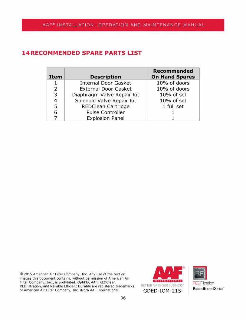
14RECOMMENDED SPARE PARTS LIST
Item DescriptionRecommended
On Hand Spares
1234567
Internal Door GasketExternal Door Gasket
Diaphragm Valve Repair KitSolenoid Valve Repair Kit
REDClean CartridgePulse ControllerExplosion Panel
10% of doors10% of doors10% of set10% of set1 full set
11

37
© 2015 American Air Filter Company, Inc. Any use of the text or
images this document contains, without permission of American AirFilter Company, Inc., is prohibited. OptiFlo, AAF, REDClean,REDFiltration, and Reliable Efficient Durable are registered trademarksof American Air Filter Company, Inc. d/b/a AAF International. GDED-IOM-215-
Serial Number
Date
Differential Pressure
Record compressed air pressure
Are solenoids operating?
Are diaphragm valves operating?
Dust disposal level recorded?
Date
Differential Pressure
Record compressed air pressure
Check hopper is empty
Dust disposal level maintained?
Date
Examine outer door gasket
Examine door cam mechanism
Is moisture present in collector?
Date
Examine cartridges
Examine outer door gasket
Examine inner door gasket
Check correct electrical operation
Examine dust disposal equipment
Examine auxiliary equipment maintenance
Date
Replace diaphragm valves as needed
Replace solenoid valves as needed
Examine inlet ductwork for dust accumulation
Examine outlet ductwork for dust accumulation
Examine and replace all air lines and DP tubing for cracks or clogging
Six Month Check
Annually
Model Number
Maintenance Log- OptiFlo RC
Daily (first week)
Weekly
Monthly
̸» ·²º±®³¿¬·±² ·² ¬¸· ¼±½«³»²¬ · ¬¸» °®±°»®¬§ ±º ß³»®·½¿² ß·® Ú·´¬»® ݱ³°¿²§ô ײ½ò øßßÚÝ×÷ ¿²¼ ³¿§ ²±¬ ¾»
½±°·»¼ ±® ¼·¬®·¾«¬»¼ ¬± ¿²§ ¬¸·®¼ °¿®¬§ô ±® «»¼ º±® ¿²§ °«®°±» ±¬¸»® ¬¸¿² ¬¸¿¬ º±® ©¸·½¸ ·¬ · «°°´·»¼ô ©·¬¸±«¬
¬¸» »¨°®» ©®·¬¬»² ½±²»²¬ ±º ßßÚÝ×ò
ɸ·´» ¬¸» ·²º±®³¿¬·±² ¸»®»·² · °®±ª·¼»¼ ·² ¹±±¼ º¿·¬¸ ¾¿»¼ ±² ·²º±®³¿¬·±² ¿ª¿·´¿¾´» ©¸»² ¬¸» ¼±½«³»²¬ ©¿
½®»¿¬»¼ô ·¬ ¸±«´¼ ²±¬ ¾» ®»´·»¼ «°±² ¿ ¾»·²¹ ½±³°´»¬» ±® ¿½½«®¿¬»ô ¿²¼ ¬¸» °®±¼«½¬ ¿¼ª»®¬·»¼ ©·¬¸·² ¬¸·
¼±½«³»²¬ô ¿²¼ ¬¸»·® ½±³°±²»²¬ ¿²¼ ¿½½»±®·»ô ¿®» «¾¶»½¬ ¬± ½¸¿²¹» ©·¬¸±«¬ ²±¬·½»ò ßßÚÝ× °®±ª·¼» ¬¸·
·²º±®³¿¬·±² ±² ¿² ßÍ ×Í ¾¿· ¿²¼ ³¿µ» ²± ©¿®®¿²¬·»ô »¨°®»»¼ ±® ·³°´·»¼ô ±® ®»°®»»²¬¿¬·±² ®»¹¿®¼·²¹
¿³»ò ̸· ¼±½«³»²¬ ¼±» ²±¬ »¬¿¾´·¸ô ¿²¼ ¸±«´¼ ²±¬ ¾» ¬¿µ»² ¿ »¬¿¾´·¸·²¹ô ¿²§ ½±²¬®¿½¬«¿´ ±® ±¬¸»®
½±³³·¬³»²¬ ¾·²¼·²¹ «°±² ßßÚÝ× ±® ¿²§ ±º ·¬ «¾·¼·¿®·» ±® ¿±½·¿¬»¼ ½±³°¿²·»ò
ßÐÝó
Û«®±°»ô Ó·¼¼´» Û¿¬
ú ߺ®·½¿
ßßÚ Ô¬¼
Þ¿·²¹¬±² Ô¿²»ô Ý®¿³´·²¹¬±²
Ò±®¬¸«³¾»®´¿²¼ô ÒÛîí èßÚ ËÕ
Ì»´æ õìì ïêéð éïí ìéé
ßßÚô Íòßò
Ýñ Ë®¿®¬»¿ô ïï
б´3¹±²± ß´·óÙ±¾»±
ðïðïð Ê·¬±®·¿ô Í°¿·²
Ì»´æ õíì çìë îïìèëï
ßßÚ Ú®¿²½»
Ϋ» É··´·¿³ Ü·¿²
ÞòÐòí
îéêîð Ù¿²§ô Ú®¿²½»
Ì»´æ õíí î íî ëí êð êð
ßßÚ Í®·
Ê·¿ Ô¿®·±ô ï
îîðéð � Ú»²»¹®. øÝÑ÷ô ׬¿´§
Ì»´æ õíç ðíï íë îë íïï
ßßÚ Ô«º¬®»·²·¹«²¹§¬»³»
Ù»³¾·ó·
Ý¿³°« îï
Û«®±°¿®·²¹ Úïî ìðï
îíìë Þ®«²² ¿³ Ù»¾·®¹»ô ß«¬®·¿
Ì»´æ õìí øð÷ îîíê êéé êîè ð
ßßÚ � Ô«º¬¬»½¸²·µ Ù³¾Ø
Ý»²¬®±¿´´» îêí ¾
Ü ìêðìé
Ѿ»®¸¿«»²ô Ù»®³¿²§
Ì»´æ õìç îðè èîèìîí ð
ßßÚ � Û²ª·®±²³»²¬¿´ ݱ²¬®±´ Û°»
ïô ׺¿·¬±« ú Õ·µ´¿¼±²
ïëíëìó Ù´·µ¿ Ò»®¿ô Ù®»»½»
Ì»´æ õíð îïðêêíîðïë
ßßÚ Ø¿ª¿ Ú·´¬®»´»®· ª» Ì·½¿®»¬ ßÍ
Ø$®®·§»¬ Ó¿¸¿´´»·
Ç¿µ¿½ïµ Üóïðð Õ«¦»§ Ç¿² DZ´ Ò±æ ìçñïóî
íìèéê Õ¿®¬¿´ô ׬¿²¾«´ô Ì«®µ»§
Ì»´æ õçð îïê ììçëïêìñêë
ßßÚ ×²¬»®²¿¬·±²¿´ � Ó·¼¼´» Û¿¬
ÚÆÍïÞÝðïóÞÝðìô Ö»¾»´ ß · Ü«¾¿·ô ËßÛ
Ì»´æ ððçéïì èèçìèèê
ßßÚ Í¿«¼· ß®¿¾·¿ Ô¬¼ò
ÐòÑò Þ±¨ ëçííê η§¿¼¸ ïïëîëô
Õ·²¹¼±³ ±º Í¿«¼· ß®¿¾·¿
Ì»´æ õçêê ï îêë ðèèí
ß·¿
ß³»®·½¿ ß·® Ú·´¬»® Ó¿²«º¿½¬«®·²¹
ͼ² Þ¸¼
Ô±¬ êô Ö¿´¿² л²¹¿°·¬ ïëñïç
Í»µ§»² ïë ìðððð ͸¿¸ ß´¿³
Í»´¿²¹±® Ü¿®«´ Û¸¿²ô Ó¿´¿§·¿
Ì»´æ øêð÷ í ëðíç éééé õêðí ëðíç ééíî
ßßÚ øÉ«¸¿²÷ ݱò Ô¬¼òô øݸ·²¿ ØÏ÷
îêè ݸ»Ý¸»²¹ α¿¼
É«¸¿² Û½±²±³·½ ú Ì»½¸²±´±¹·½¿´
Ü»ª»´±°³»²¬ Ʊ²»
É«¸¿²ô Ø«¾»· Ю±ª·²½» ÐÎô
ݸ·²¿ ìíððëê
Ì»æ õèê îé èììé íêéï õèê îé èììé íêéî
ßßÚ ×²¬»®²¿¬·±²¿´ ø̸¿· ¿²¼÷ ݱòô Ô¬¼ò
ïðð Ó±± ì ͱ· Ò¿³¼¿²¹ � Þ¿²¹°´»» ìì
Þ¿²¹µ¿»© Þ¿²¹°´»»ô Í¿³«¬°®¿µ¿®²
ïðëìðô ̸¿·´¿²¼
Ì»´æ õêê îéíè ééèè
Ü¿·µ·² ß«¬®¿´·¿ Ь§ Ô¬¼
ïë Ò§¿¼¿´» α¿¼ ͽ±®»¾§ Ê·½¬±®·¿ íïéçô
ß«¬®¿´·¿
Ì»´æ õêï øð÷í çîíé ëëêî
Ò±®¬¸ ú ͱ«¬¸ ß³»®·½¿
ßßÚ ×²¬»®²¿¬·±²¿´
ççîð ݱ®°±®¿¬» Ý¿³°« Ü®·ª»ô Í«·¬» îîðð
Ô±«·ª·´´»ô ÕÇ ìðîîíóëðððô ËÍß
Ì»´æ ï ëðî êíé ððïï
̱´´ Ú®»»æ ï èðð ìéé ïîïì
ßßÚô Í ¼» ÎÔ ¼» ÝÊ
ߪò Ю·³»®± ¼» Ó¿§± Ò±ò èëô
ݱ´ò Í¿² ß²¼®7 ߬»²½±ô
ÝòÐò ëìðìð Ì·¿´²»°¿²¬´¿ Û¼±ò
Ü» Ó»¨·½±ô Ó7¨·½±
Ì»´æ õëî ëë ëëêë ëîðð
ß³»®·½¿² ß·® Ú·´¬»® Þ®¿·´ Ô¬¼¿ò
Ϋ¿ ܱ«¬±® Þ¿½»´¿®ô ïéíóÝÖò ïîï
Ê·´¿ Ý´»³»²¬·²± � Í=± п«´± � Þ®¿¦·´
ÝÛÐ ðìðîêóððð
Ì»´æ õëë ïï ëëêé íððð