Optics Overview - MIT OpenCourseWare · integrated optics • Cylindrically symmetric version:...
41
Optics Overview MIT 2.71/2.710 Review Lecture p-1
Transcript of Optics Overview - MIT OpenCourseWare · integrated optics • Cylindrically symmetric version:...

Optics Overview
MIT 2.71/2.710 Review Lecture p-1

What is light?
• Light is a form of electromagnetic energy – detected through its effects, e.g. heating of illuminated objects, conversion of light to current, mechanical pressure (“Maxwell force”) etc.
• Light energy is conveyed through particles: “photons” – ballistic behavior, e.g. shadows
• Light energy is conveyed through waves – wave behavior, e.g. interference, diffraction
• Quantum mechanics reconciles the two points of view, through the “wave/particle duality” assertion
MIT 2.71/2.710 Review Lecture p-2

Particle properties of light
Photon=elementary light particle
Mass=0 Speed c=3×10⁸ m/sec
According to Special Relativity, a massAccording to Special Relativity, a mass--less particle travellingless particle travellingat light speed can still carry momentum!at light speed can still carry momentum!
relates the dual particle & waveEnergy E=hν nature of light;
h=Planck’s constant ν is the temporal oscillation=6.6262×10⁻³⁴ J sec frequency of the light waves
MIT 2.71/2.710 Review Lecture p-3

Wave properties of light
λ1/ν
angular frequency
λ: wavelength (spatial period)
k=2π/λ wavenumber
ν: temporal frequency
ω=2πν
E: electric field
MIT 2.71/2.710 Review Lecture p-4
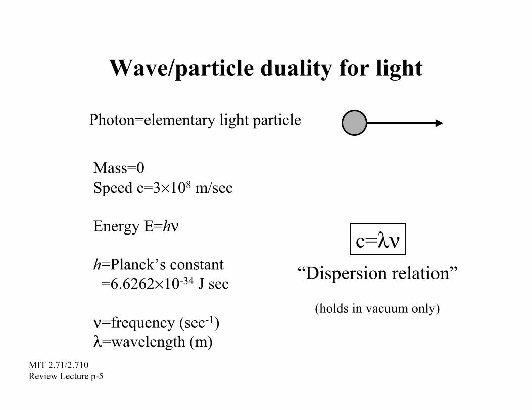
Wave/particle duality for light
Photon=elementary light particle
Mass=0 Speed c=3×10⁸ m/sec
Energy E=hν
h=Planck’s constant c=λν
“Dispersion relation”=6.6262×10⁻³⁴ J sec (holds in vacuum only)
ν=frequency (sec-1) λ=wavelength (m)
MIT 2.71/2.710 Review Lecture p-5

Light in matter
light in vacuum
light in matter
Speed c=3×10⁸ m/sec Speed c/n n : refractive index (or index of refraction)
Absorption coefficient 0 Absorption coefficient α energy decay coefficient, after distance L : e–2αL
E.g. vacuum n=1, air n ≈ 1; glass n≈1.5; glass fiber has α ≈0.25dB/km=0.0288/km
MIT 2.71/2.710 Review Lecture p-6

Materials classification
• Dielectrics – typically electrical isolators (e.g. glass, plastics) – low absorption coefficient – arbitrary refractive index
• Metals – conductivity ⇒ large absorption coefficient
• Lots of exceptions and special cases (e.g. “artificial dielectrics”) • Absorption and refractive index are related through the Kramers–
Kronig relationship (imposed by causality) absorption
ν
refractive index
MIT 2.71/2.710 Review Lecture p-7

Overview of light sourcesnon-Laser
Thermal: polychromatic, spatially incoherent (e.g. light bulb)
Gas discharge: monochromatic, spatially incoherent (e.g. Na lamp)
Light emitting diodes (LEDs):monochromatic, spatially incoherent
Laser Continuous wave (or cw):strictly monochromatic, spatially coherent (e.g. HeNe, Ar+, laser diodes)
Pulsed: quasi-monochromatic, spatially coherent (e.g. Q-switched, mode-locked)
~nsec ~psec to few fsec
pulse duration
mono/poly-chromatic = single/multi colorMIT 2.71/2.710 Review Lecture p-8

Monochromatic, spatially coherent
λ1/ν • λ, ν well defined
description
light • nice, regular sinusoid
• stabilized HeNe laser good approximation • most other cw lasers rough approximation • pulsed lasers & non-laser sources need more complicated
Incoherent: random, irregular waveform
MIT 2.71/2.710 Review Lecture p-9

The concept of a monochromatic “ray”
direction of energy propagation:
light ray
z
λ
t=0 (frozen)
wavefronts
In homogeneous media,light propagates in rectilinear paths
MIT 2.71/2.710 Review Lecture p-10

The concept of a monochromatic “ray”
direction of energy propagation:
light ray
z
λ
t=∆t (advanced)
wavefronts
In homogeneous media,light propagates in rectilinear paths
MIT 2.71/2.710 Review Lecture p-11

The concept of a polychromatic “ray”
t=0 z(frozen)
energy from pretty much
all wavelengths propagates along
the raywavefronts
In homogeneous media,light propagates in rectilinear paths
MIT 2.71/2.710 Review Lecture p-12

Fermat principle
light ray
Γ
P
P’
Γ is chosen to minimize this z y x n ) dl “path” integral, compared to ( , ,∫Γ alternative paths
(aka minimum path principle)Consequences: law of reflection, law of refraction
MIT 2.71/2.710 Review Lecture p-13
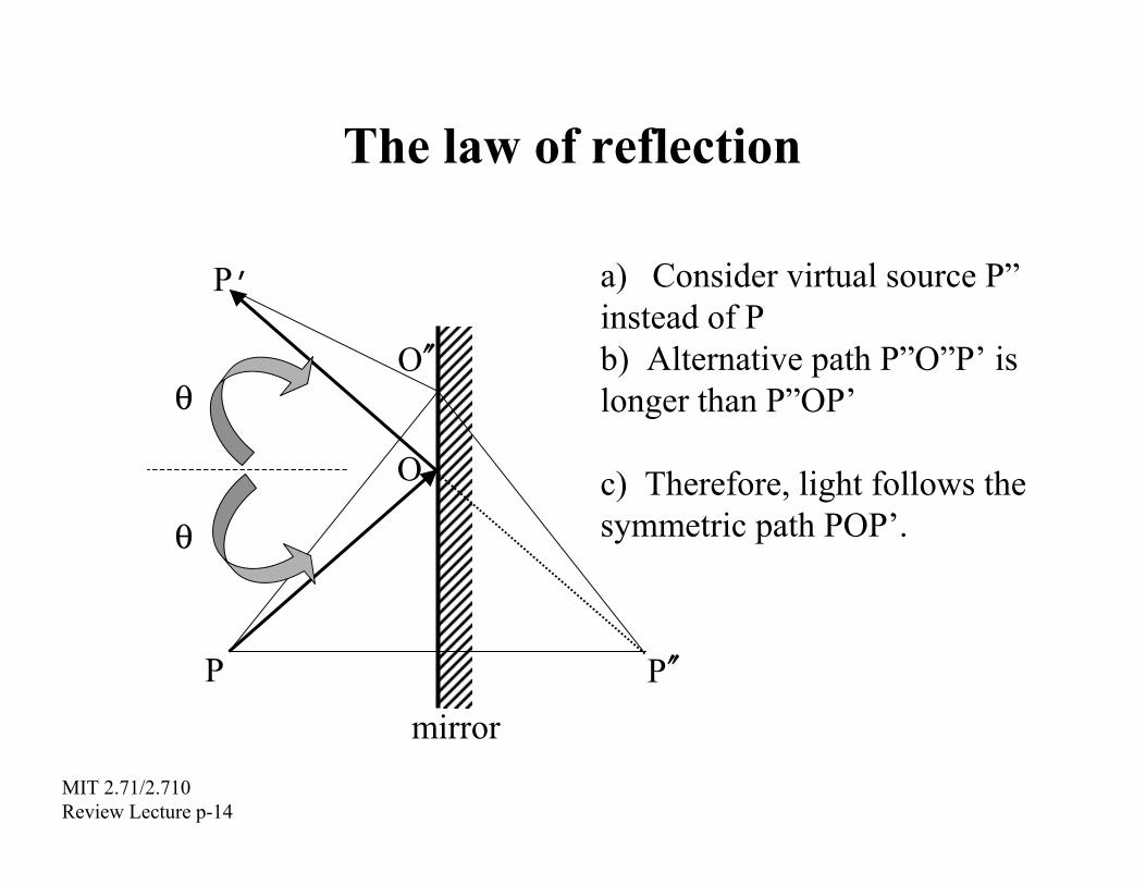
The law of reflection
P
P’
O
O
a) instead of P b) Alternative path P”O”P’ is longer than P”OP’
c) Therefore, light follows the
θ
θ
′′
symmetric path POP’.
P ′′
mirror
Consider virtual source P”
MIT 2.71/2.710 Review Lecture p-14

The law of refraction
θ
θ
θ′
n n′
reflected
refracted
incident
θθ ′′= sinsin nn Snell’s Law of Refraction
MIT 2.71/2.710 Review Lecture p-15

Optical waveguide
TIR
TIR n
n
nn≈
=1.51
=1.5105
=1.51 1.00
• Planar version: integrated optics • Cylindrically symmetric version: fiber optics • Permit the creation of “light chips” and “light cables,” respectively, where light is guided around with few restrictions • Materials research has yielded glasses with very low losses (<0.25dB/km) • Basis for optical telecommunications and some imaging (e.g. endoscopes) and sensing (e.g. pressure) systems
MIT 2.71/2.710 Review Lecture p-16

Refraction at a spherical surface
point source
MIT 2.71/2.710 Review Lecture p-17
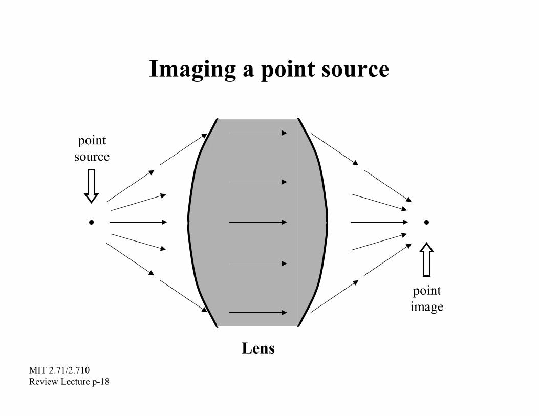
Imaging a point source
point source
point image
LensMIT 2.71/2.710 Review Lecture p-18
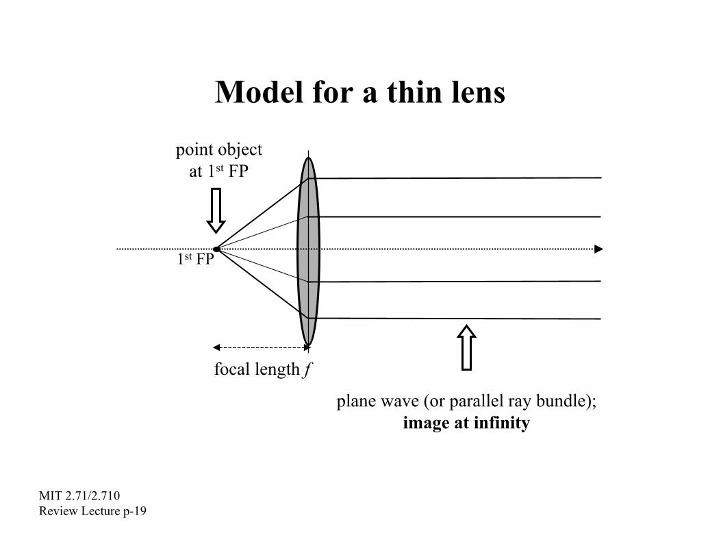
Model for a thin lens
1st FP
at 1st FP
f
point object
focal length
plane wave (or parallel ray bundle); image at infinity
MIT 2.71/2.710 Review Lecture p-19

Model for a thin lens
at 2nd FP
f
point image
focal length
plane wave (or parallel ray bundle); object at infinity
MIT 2.71/2.710 Review Lecture p-20
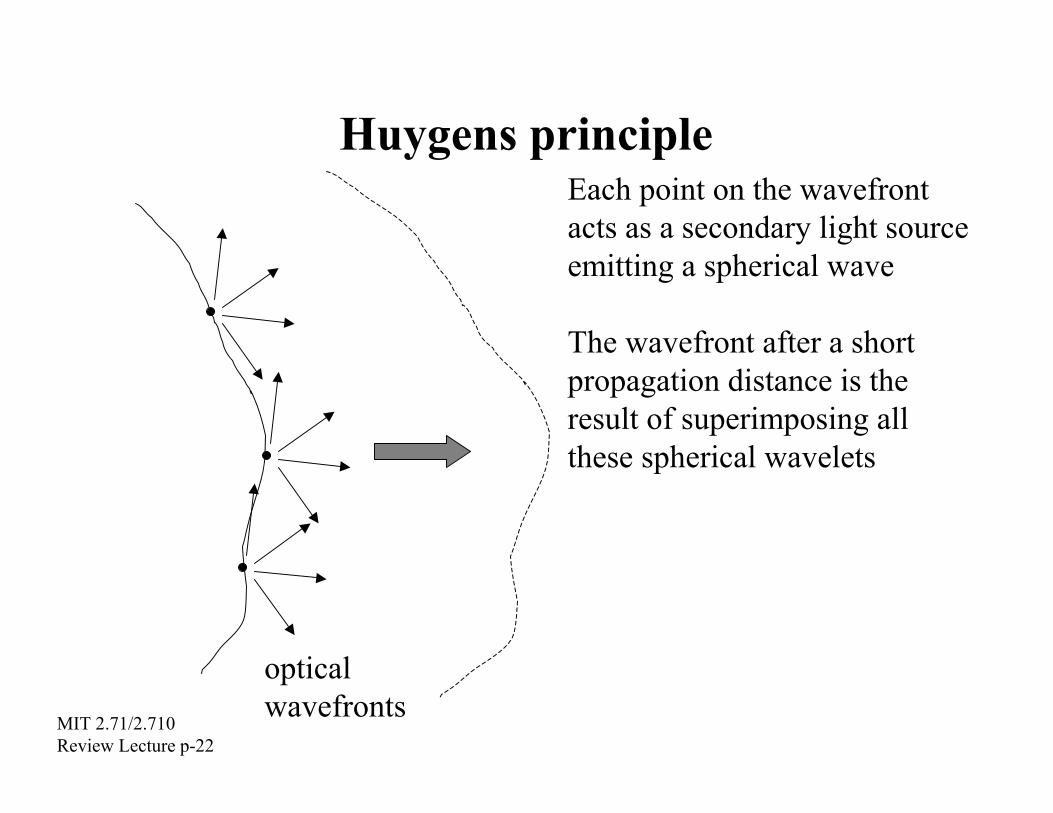
Huygens principle
optical MIT 2.71/2.710
Each point on the wavefront acts as a secondary light source emitting a spherical wave
The wavefront after a short propagation distance is the result of superimposing all these spherical wavelets
wavefronts Review Lecture p-22

Why imaging systems are needed
• Each point in an object scatters the incident illumination into a spherical wave, according to the Huygens principle.
• A few microns away from the object surface, the rays emanating from all object points become entangled, delocalizing object details.
• To relocalize object details, a method must be found to reassign (“focus”) all the rays that emanated from a single point object into another point in space (the “image.”)
• The latter function is the topic of the discipline of Optical Imaging.
MIT 2.71/2.710 Review Lecture p-23

Imaging condition: ray-tracing
2nd FP 1st FP
object
(real)
chief ray
thin lens (+)
image
• Image point is located at the common intersection of all rays which emanate from the corresponding object point
• The two rays passing through the two focal points and the chief ray can be ray-traced directly
• The real image is inverted and can be magnified or demagnified
MIT 2.71/2.710 Review Lecture p-24
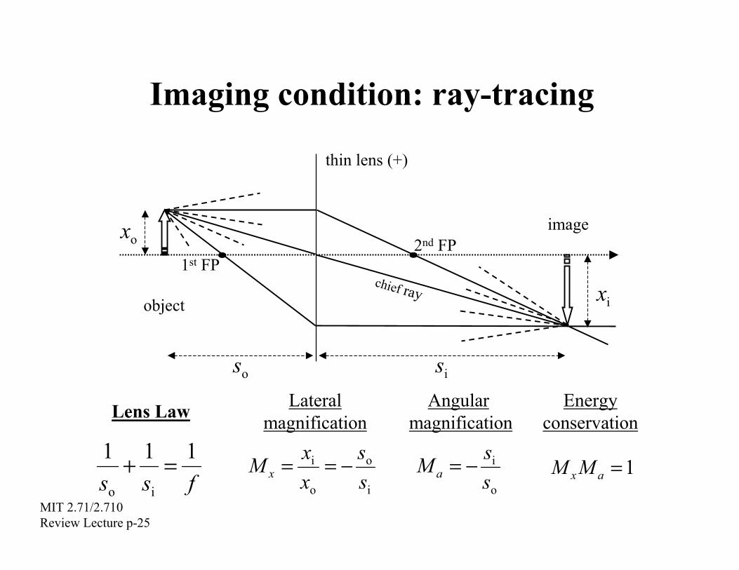
Imaging condition: ray-tracing
2nd FP 1st FP
object chief ray
thin lens (+)
s s
ox
ix
image
io
Lateral Angular EnergyLens Law magnification magnification conservation 1 1 1
Mss
xx
oi − = o i
Mss
i− = o
M M x + = = = f s s o
MIT 2.71/2.710 Review Lecture p-25
x a a i
1

Imaging condition: ray-tracing
2nd FP 1st FP object
(virtual)
chief ray
thin lens (+)
image
• The ray bundle emanating from the system is divergent; the virtual image is located at the intersection of the backwards-extended rays • The virtual image is erect and is magnified • When using a negative lens, the image is always virtual, erect, and demagnified
MIT 2.71/2.710 Review Lecture p-26
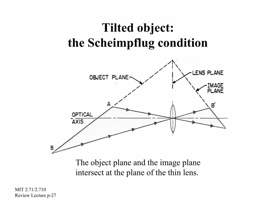
Tilted object:the Scheimpflug condition
The object plane and the image planeintersect at the plane of the thin lens.
MIT 2.71/2.710 Review Lecture p-27

Lens-based imaging
• Human eye • Photographic camera
• Magnifier • Microscope • Telescope
MIT 2.71/2.710 Review Lecture p-28

The human eye
Remote object (unaccommodated eye)
Near object (accommodated eye)
MIT 2.71/2.710 Review Lecture p-29

The photographic camera
Film or
)
detector array (CCD or CMOS) “digital imaging”
meniscus lens
or (nowadayszoom lens
MIT 2.71/2.710 Review Lecture p-31

The pinhole camera
object
image opaque screen
pinhole
• The pinhole camera blocks all but one ray per object point from reaching the image space ⇒ an image is formed (i.e., each point in image space corresponds to a single point from the object space). • Unfortunately, most of the light is wasted in this instrument. • Besides, light diffracts if it has to go through small pinholes as we will see later; diffraction introduces undesirable artifacts in the image.
MIT 2.71/2.710 Review Lecture p-35
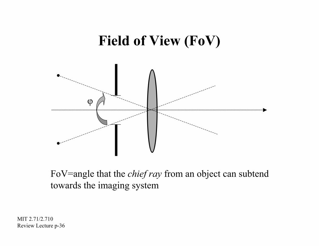
Field of View (FoV)
φ
FoV=angle that the chief ray from an object can subtend towards the imaging system
MIT 2.71/2.710 Review Lecture p-36

Numerical Aperture
n
θ
medium of refr. index
Numerical Aperture θ: half-angle subtended by (NA) = n sinθ the imaging system from an axial object Speed (f/#)=1/2(NA)
pronounced f-number, e.g. f/8 means (f/#)=8.
MIT 2.71/2.710 Review Lecture p-37

Resolution
?δx
How far can two distinct point objects bebefore their images cease to be distinguishable?
MIT 2.71/2.710 Review Lecture p-38

Factors limiting resolution in an imaging system
Intricately related; assessment of image quality depends on the degree that the “inverse
• Diffraction
• Aberrations problem” is solvable (i.e. its condition) 2.717 sp02 for details • Noise
– electronic noise (thermal, Poisson) in cameras – multiplicative noise in photographic film – stray light – speckle noise (coherent imaging systems only)
• Sampling at the image plane – camera pixel size – photographic film grain size
MIT 2.71/2.710 Review Lecture p-39

Point-Spread Function
Light distribution (rotationally near the Gaussian = PSF symmetric (geometric) focus wrt optical axis)
Point source (ideal) NA
~ λ x∆ 22.1
2λ∆z ~ NA2
The finite extent of the PSF causes blur in the image
MIT 2.71/2.710 Review Lecture p-40

Diffraction limited resolution
object spacing
)
)
δx
lateral coordinate at image plane (arbitrary units
light
inte
nsity
(arb
itrar
y un
its
Point objects “just δx ≈ 22.1 λ Rayleigh resolution resolvable” when (NA) criterion
MIT 2.71/2.710 Review Lecture p-41

Wave nature of light
• Diffraction
broadening of point images
diffraction grating • Inteference
??
? Fabry-Perot interferometer Interference filter
Michelson interferometer (or dielectric mirror)
• Polarization: polaroids, dichroics, liquid crystals, ...
MIT 2.71/2.710 Review Lecture p-42

Diffraction gratingincident
Grating spatial frequency: 1/ΛΛΛΛplane Angular separation between diffracted orders: ∆∆∆∆θθθθ ≈≈≈≈1/ΛΛΛΛwave
Λ m=1
……
m=3
m=2
m=–1
m=–2 m=–3
m=0 “straight-through” order or DC term
Condition for constructive interference:
= Λ ππ mm integer)(22 λ
λ ⇔ sinθ = m Λ
MIT 2.71/2.710 diffraction order Review Lecture p-43

Grating dispersion
Anomalous (or negative)
dispersion
polychromatic(white)
lightGlass prism: normal dispersion
MIT 2.71/2.710 Review Lecture p-44

Fresnel diffraction formulaex
y
z
x´
y´
),(out yxg ′′( )g ,in y x 2 2( x ′ − x ) + ( y ′ − y )
y x d d 1
λx
y
z
x´
y´
outG( )G ,in v u
z ( , )g out ( ′ ′ z y x , ; ) 2π i π= exp i ∫g y x expinz i λ λ z
,( v u )
G out , ;( z v u )
= exp i G inλ
{ (-exp i u z )}z ( v u ) 2 22π πλ + v, MIT 2.71/2.710 Review Lecture p-45
1
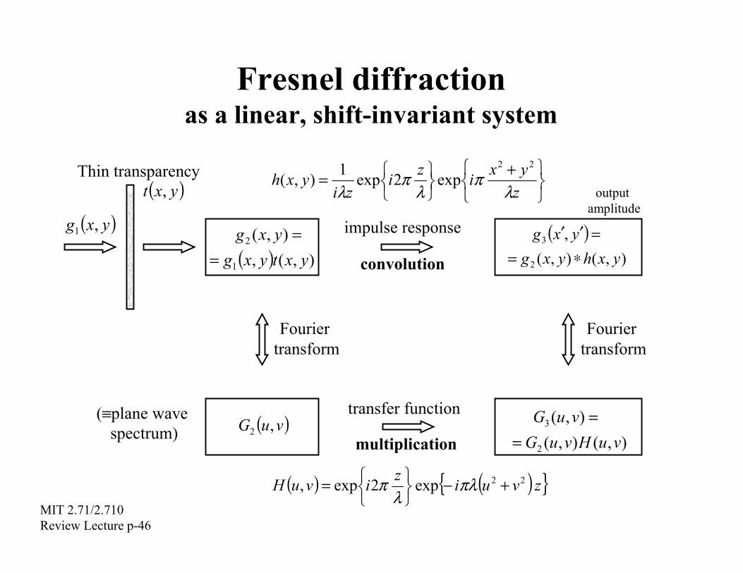
Fresnel diffraction as a linear, shift-invariant system
2x + y 2
λz
Thin transparency y x h = 1
) ( , i π
exp i
z λ
2π) exp( y x t , z i λ output amplitude
( ) ( ) ),(,
),(
1
2
g g
=
=
y x t y x y x ( )
),(),( ,
2
3
g g
∗=
= ′′ y x h y x
y x impulse response
convolution
g y x ,
Fourier Fourier transform transform
(≡ ) ( )G ,2
λ
),(),( ),(
2
3
G G
=
=
multiplication
plane wave spectrum v u
transfer function
v u H v u v u
exp{− πλ( u ) }z( v u ) 2 + 2H = exp i 2π i v z, MIT 2.71/2.710 Review Lecture p-46