
Optically Efficient Homogenization of Laser Illumination · Optically Efficient Homogenization of...
3
Optically Efficient Homogenization of Laser Illumination Fergal Shevlin DYOPTYKA, 7 Westland Court, South Cumberland St., Dublin 2, Ireland. Keywords: Projection display, laser illumination, intensity homogenization, speckle. Abstract DYOPTYKA’s innovative deformable mirror technology is shown to achieve effective and efficient intensity ho- mogenization of laser illumination and speckle reduction in a projection display optical system. Performance is found to be similar to an approach which uses one stationary and one moving diffuser but with significantly improved optical efficiency. 1 Background Laser diodes have certain advantages for projection displays in comparison to LEDs, in particular their greater optical power so that fewer sources are required and their lower ´ etendue for more optically efficient coupling into the illumination optical system. However optical efficiency is not optimized when a diffuser is used to increase ´ etendue to fill the entrance aperture(s) of the illumination homogenization and shaping optical system of microdisplay-based projectors. Even carefully designed and fabricated diffusers with relatively smooth surfaces have Fresnel reflection losses and scatter some illumination at high angles such that it misses the entrance aperture(s.) Another problem arising from the use of diffusers is that they create strong interference patterns in the projected image. These are one manifestation of the phenomenon of speckle [1] which can seriously degrade image quality. The conventional solution to making interference patterns less perceptible is to move the diffuser to create many uncorrelated patterns which sum to a more homogeneous intensity over time, see Figure 1. 2 Objectives To demonstrate how optical efficiency can be improved by using DYOPTYKA’s phase-randomizing deformable mir- ror technology (see Figure 2,) without any of diffuser(s,) to increase ´ etendue so as to achieve good homogenization of illumination intensity and reduction of speckle contrast. 3 Apparatus The projection display parameters chosen for this investigation are those of a near-to-wall television with 150× magnification of a 0.65” DLP microdisplay for an approximately 100” image through an f/2.4 projection optical system. Although a multi-LD array with about 30 W optical power would be required for sufficient brightness, for ease of laboratory experimentation we used a single 1 W multimode laser diode and a small deformable mirror. The experimental apparatus is shown Figure 1: The field illuminated by different configurations of the projection apparatus used in this study. [Above, left] With no diffuser, various inhomogeneities are evident: modal structure of laser diode; interference fringes arising from dust, scratches, and misalignments in the illumination and projection optical systems; incomplete distribution of illumination. [Above, right] With a 2 “engineered diffuser” before homogenizing rod: strong pattern due to diffuser structure; [Below, right] With a second diffuser of the same characteristics positioned after the first: more complete distribution of illumination but strong pattern visible; [Below, left] With second diffuser rotating at approx. 10,000 RPM: significant improvement. and described in more detail in Figure 3. Camera magnification was chosen such that image resolution was approximately equal to that of a human observer located at the nominal screen diagonal distance. Camera lens f/# was chosen such that speckle contrast in the acquired imagery was approximately equal to that perceived by a human observer. This is a highly subjective approach but we felt it appropriate to ensure that speckle is more realistically represented in acquired imagery than is sometimes the case in the published literature. 4 Procedure and results We operated the apparatus mostly in two different configurations: no diffuser(s) and deformable mirror active; one stationary diffuser, one moving diffuser, and deformable mirror inactive. Table 1 summarizes our measurements and observations which are discussed in 1
-
Upload
doankhuong -
Category
Documents
-
view
216 -
download
2
Transcript of Optically Efficient Homogenization of Laser Illumination · Optically Efficient Homogenization of...

Optically Efficient Homogenization of Laser Illumination
Fergal Shevlin
DYOPTYKA, 7 Westland Court, South Cumberland St., Dublin 2, Ireland.
Keywords: Projection display, laser illumination, intensity homogenization, speckle.
Abstract
DYOPTYKA’s innovative deformable mirror technologyis shown to achieve effective and efficient intensity ho-mogenization of laser illumination and speckle reductionin a projection display optical system. Performanceis found to be similar to an approach which uses onestationary and one moving diffuser but with significantlyimproved optical efficiency.
1 Background
Laser diodes have certain advantages for projectiondisplays in comparison to LEDs, in particular theirgreater optical power so that fewer sources are requiredand their lower etendue for more optically efficientcoupling into the illumination optical system.
However optical efficiency is not optimized when adiffuser is used to increase etendue to fill the entranceaperture(s) of the illumination homogenization andshaping optical system of microdisplay-based projectors.Even carefully designed and fabricated diffusers withrelatively smooth surfaces have Fresnel reflection lossesand scatter some illumination at high angles such thatit misses the entrance aperture(s.)
Another problem arising from the use of diffusersis that they create strong interference patterns in theprojected image. These are one manifestation of thephenomenon of speckle [1] which can seriously degradeimage quality. The conventional solution to makinginterference patterns less perceptible is to move thediffuser to create many uncorrelated patterns which sumto a more homogeneous intensity over time, see Figure 1.
2 Objectives
To demonstrate how optical efficiency can be improved byusing DYOPTYKA’s phase-randomizing deformable mir-ror technology (see Figure 2,) without any of diffuser(s,)to increase etendue so as to achieve good homogenizationof illumination intensity and reduction of speckle contrast.
3 Apparatus
The projection display parameters chosen for thisinvestigation are those of a near-to-wall television with150× magnification of a 0.65” DLP® microdisplay for anapproximately 100” image through an f/2.4 projectionoptical system. Although a multi-LD array with about30 W optical power would be required for sufficientbrightness, for ease of laboratory experimentation weused a single 1 W multimode laser diode and a smalldeformable mirror. The experimental apparatus is shown
Figure 1: The field illuminated by different configurationsof the projection apparatus used in this study. [Above,left] With no diffuser, various inhomogeneities are evident:modal structure of laser diode; interference fringesarising from dust, scratches, and misalignments in theillumination and projection optical systems; incompletedistribution of illumination. [Above, right] With a 2°“engineered diffuser” before homogenizing rod: strongpattern due to diffuser structure; [Below, right] With asecond diffuser of the same characteristics positioned afterthe first: more complete distribution of illumination butstrong pattern visible; [Below, left] With second diffuserrotating at approx. 10,000 RPM: significant improvement.
and described in more detail in Figure 3.Camera magnification was chosen such that image
resolution was approximately equal to that of a humanobserver located at the nominal screen diagonal distance.Camera lens f/# was chosen such that speckle contrastin the acquired imagery was approximately equal to thatperceived by a human observer. This is a highly subjectiveapproach but we felt it appropriate to ensure that speckleis more realistically represented in acquired imagery thanis sometimes the case in the published literature.
4 Procedure and results
We operated the apparatus mostly in two differentconfigurations: no diffuser(s) and deformable mirroractive; one stationary diffuser, one moving diffuser, anddeformable mirror inactive. Table 1 summarizes ourmeasurements and observations which are discussed in
1

Figure 2: Deformable mirror in inactive and active states.Central region is actuated at hundreds of kHz resulting inrandomly-distributed surface deformations which achieveeffective and efficient divergence, inter-modal dispersionin waveguides, and the generation of uncorrelated specklepatterns. Reflection efficiency is approximately 98%.
Deformablemirror
Diffusers
IntensityLow gain 47% 30%High gain 65% 43%
SpeckleLow gain 6% 6%High gain 16% 16%
HomogeneityLow gain Good BetterHigh gain Good Better
Table 1: Subjective observations about homogeneity ofthe illuminated field shown in Figure 4. Also mean pixelgray level intensities (relative to maximum sensor value)and speckle contrast ratios of the small regions shownin Figure 5 (values rounded to nearest integers.)
further detail in the following sections.
We operated the apparatus also with only one movingdiffuser and deformable mirror inactive. However thehomogeneity was so poor it was not possible to makea meaningful comparisons with the other configurations.
5 Homogeneity
The intensity distribution across the field is not asgood with the deformable mirror only as with the twodiffusers. It is possible that a longer homogenizing rodwould help, as would cleaner and better aligned optics.In our previous work much better homogeneity wasachieved through the use of microlens arrays instead ofa homogenizing rod [2] but we used a rod here because itis the most common approach for DLP®. However ourexpectation is that the use of a multi-LD array instead ofa single source should lead to a significant improvement.
6 Speckle
The speckle contrast ratios for both configurationsare effectively the same. This is in accordance withthe theory that the limit is inversely proportional tothe sensor spot size divided by the projection lensdiffraction-limited spot size [1].
Figure 3: [Above] Experimental illumination andprojection apparatus. Components clockwise frombelow-left: Roithner LaserTechnik 450 nm multimodelaser diode delivering approximately 1 W optical power;An f =4.51mm lens to reduce divergence so that onlythe central region of the deformable mirror is illuminated;Kinematic mount holding deformable mirror and firstRPC Photonics model EDS 2° engineered diffuser; Second2° engineered diffuser mounted such that it can be rotatedat approx. 10,000 RPM; An f =4.51mm lens positionedsuch that the exit f/# of the illumination optical systemis approximately f/2.4; Homogenizing rod of dimensions6× 8× 50mm3. Although this rod has only half thecross-sectional area of a 0.65” microdisplay, it was chosenbecause of the reduced optical power available; Projectionlens from DLP® projector with a rectangular stop addedto approximate f/2.4; Since the projection lens was notwide angle, the apparatus was positioned approximately5 m from the illuminated field for 150× magnification.[Below] Region of illuminated field comprising materialswith different surface roughness characteristics: paperbusiness card; low gain, relatively rough diffusing surfaceof painted wall; high gain, polarization-preserving 3-Dcinema screen sample (with holes for sound transmission;)and smooth plastic ruler. Note that this image wasacquired using broadband, non-coherent, diffuse illumi-nation. When illuminated with monochromatic, coherent,directional illumination through the projection apparatus,the high gain screen sample has a more irregular intensitydue to it not being flat, see Figure 4 for example.
7 Optical Efficiency
The deformable mirror only configuration is approximately1.5 times brighter than the two diffuser configuration forboth low-gain and high-gain materials. For increased con-fidence in our observations we simplified the apparatus bypositioning a beam profiler directly after the exit face ofthe homogenizing rod. The imagery acquired is shown in
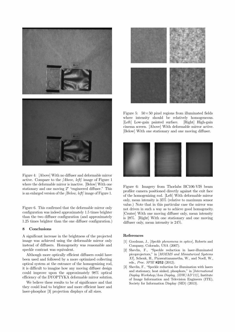
Figure 4: [Above] With no diffuser and deformable mirroractive. Compare to the [Above, left] image of Figure 1where the deformable mirror is inactive. [Below] With onestationary and one moving 2° “engineered diffuser.” Thisis an enlarged version of the [Below, left] image of Figure 1.
Figure 6. This confirmed that the deformable mirror onlyconfiguration was indeed approximately 1.5 times brighterthan the two diffuser configuration (and approximately1.25 times brighter than the one diffuser configuration.)
8 Conclusions
A significant increase in the brightness of the projectedimage was achieved using the deformable mirror onlyinstead of diffusers. Homogeneity was reasonable andspeckle contrast was equivalent.
Although more optically efficient diffusers could havebeen used and followed by a more optimized collectingoptical system at the entrance of the homogenizing rod,it is difficult to imagine how any moving diffuser designcould improve upon the approximately 98% opticalefficiency of the DYOPTYKA deformable mirror solution.
We believe these results to be of significance and thatthey could lead to brighter and more efficient laser andlaser-phosphor [3] projection displays of all sizes.
Figure 5: 50×50 pixel regions from illuminated fieldswhere intensity should be relatively homogeneous.[Left] Low-gain painted surface. [Right] High-gaincinema screen. [Above] With deformable mirror active.[Below] With one stationary and one moving diffuser.
Figure 6: Imagery from Thorlabs BC106-VIS beamprofiler camera positioned directly against the exit faceof the homogenizing rod. [Left] With deformable mirroronly, mean intensity is 35% (relative to maximum sensorvalue.) Note that in this particular case the mirror wasnot driven in such a way as to achieve good homogeneity.[Center] With one moving diffuser only, mean intensityis 28%. [Right] With one stationary and one movingdiffuser only, mean intensity is 24%.
References
[1] Goodman, J., [Speckle phenomena in optics], Roberts andCompany, Colorado, USA (2007).
[2] Shevlin, F., “Speckle reduction in laser-illuminatedpicoprojectors,” in [MOEMS and Miniaturized SystemsXI], Schenk, H., Piyawattanametha, W., and Noell, W.,eds., Proc. SPIE 8252 (2012).
[3] Shevlin, F., “Speckle reduction for illumination with lasersand stationary, heat sinked, phosphors,” in [InternationalDisplay Workshop/Asia Display, (IDW/AD’13)], Instituteof Image Information and Television Engineers (ITE),Society for Information Display (SID) (2013).