Optical Networking. Introduction: What and why.... Implementing Optical Networking Developments...
46
Optical Networking
-
Upload
nathaniel-ramsey -
Category
Documents
-
view
231 -
download
1
Transcript of Optical Networking. Introduction: What and why.... Implementing Optical Networking Developments...
Optical Networking
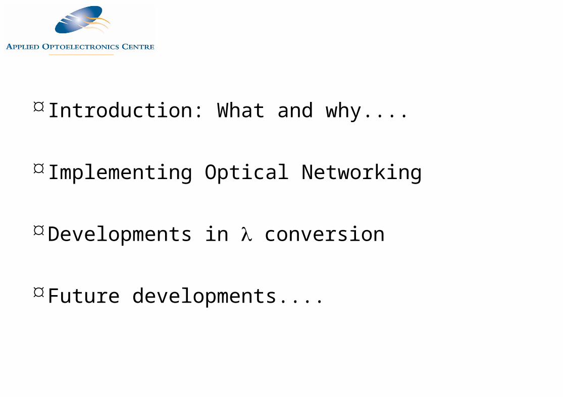
Introduction: What and why....
Implementing Optical Networking
Developments in conversion
Future developments....
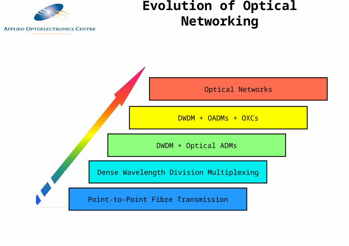
Point-to-Point Fibre Transmission
Dense Wavelength Division Multiplexing
DWDM + Optical ADMs
DWDM + OADMs + OXCs
Optical Networks
Evolution of Optical Networking
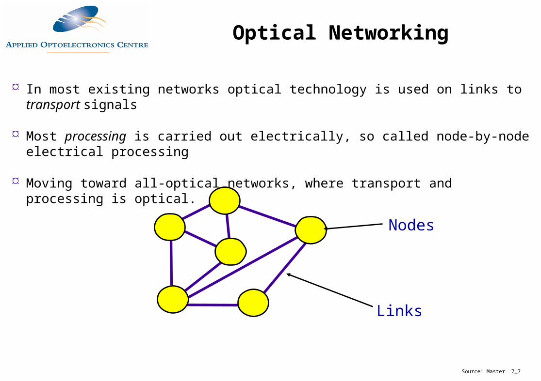
In most existing networks optical technology is used on links to transport signals
Most processing is carried out electrically, so called node-by-node electrical processing
Moving toward all-optical networks, where transport and processing is optical.
Links
Nodes
Source: Master 7_7
Optical Networking
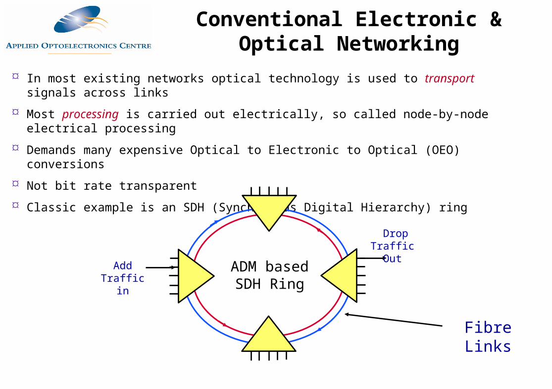
In most existing networks optical technology is used to transport signals across links
Most processing is carried out electrically, so called node-by-node electrical processing
Demands many expensive Optical to Electronic to Optical (OEO) conversions
Not bit rate transparent
Classic example is an SDH (Synchronous Digital Hierarchy) ring
Fibre Links
ADM based SDH Ring
Add Traffic in
Drop Traffic Out
Conventional Electronic & Optical Networking
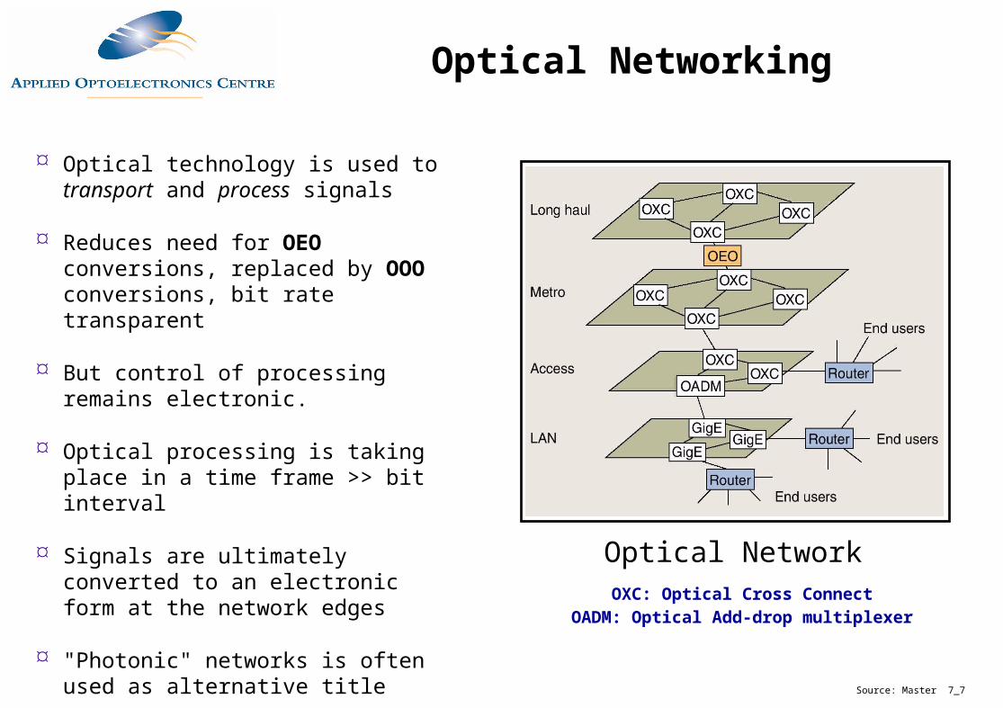
Optical technology is used to transport and process signals
Reduces need for OEO conversions, replaced by OOO conversions, bit rate transparent
But control of processing remains electronic.
Optical processing is taking place in a time frame >> bit interval
Signals are ultimately converted to an electronic form at the network edges
"Photonic" networks is often used as alternative title
Source: Master 7_7
Optical NetworkOXC: Optical Cross Connect
OADM: Optical Add-drop multiplexer
Optical Networking
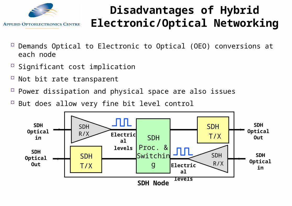
Demands Optical to Electronic to Optical (OEO) conversions at each node
Significant cost implication
Not bit rate transparent
Power dissipation and physical space are also issues
But does allow very fine bit level control
SDH Optical
Out
SDH T/X
SDH R/X Electrical
levels
SDH Optical in
SDHT/X
SDH R/XElectrical
levels
SDH Optical in
SDH Optical
Out
SDHProc. &
Switching
SDH Node
Disadvantages of Hybrid Electronic/Optical Networking
A. J. Poustie, R. J. Manning and A. Kelley @ BT Labs
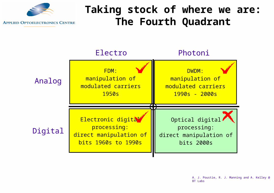
Analog
Digital
Electronic Photonic
FDM:manipulation of
modulated carriers1950s
Optical digitalprocessing:
direct manipulation ofbits 2000s
DWDM:manipulation of
modulated carriers1990s - 2000s
Electronic digitalprocessing:
direct manipulation ofbits 1960s to 1990s
Taking stock of where we are: The Fourth Quadrant
Driving forces:
The "electronic bit-rate bottleneck"
The complexity/inflexibility/cost of hybrid electronic/optical systems
The demand for more bandwidth
Development of simple optical processing elements
Widespread deployment of Dense Wavelength Division Multiplexing
Potential for exploitation of the full capacity of singlemode fibre
Why Optical Networking?
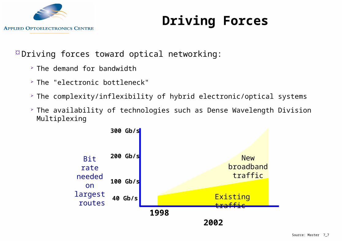
Driving forces toward optical networking:
The demand for bandwidth
The "electronic bottleneck"
The complexity/inflexibility of hybrid electronic/optical systems
The availability of technologies such as Dense Wavelength Division Multiplexing
1998 2002
300 Gb/s
200 Gb/s
100 Gb/s
40 Gb/s Existing traffic
New broadband
traffic
Bit rate needed on
largest routes
Source: Master 7_7
Driving Forces
1996 1998 2000 2002 2004 20060
5
10
15
20
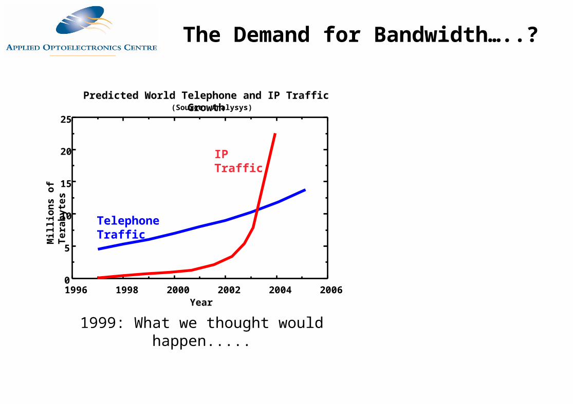
25(Source: Analysys)
Predicted World Telephone and IP Traffic Growth
IP Traffic
Telephone Traffic
Mil
lio
ns
of
Ter
abyt
es
Year
1999: What we thought would happen.....
The Demand for Bandwidth…..?
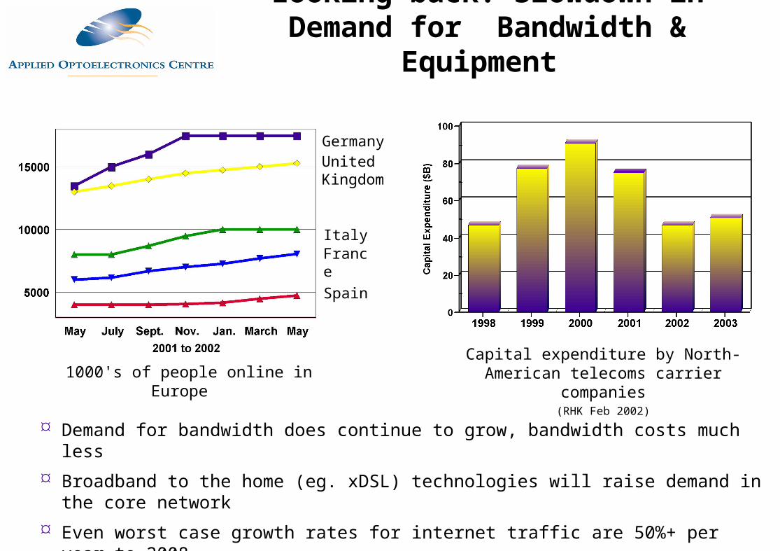
Capital expenditure by North-American telecoms carrier companies
(RHK Feb 2002)
GermanyUnited Kingdom
ItalyFrance
Spain
1000's of people online in Europe
Demand for bandwidth does continue to grow, bandwidth costs much less
Broadband to the home (eg. xDSL) technologies will raise demand in the core network
Even worst case growth rates for internet traffic are 50%+ per year to 2008
Looking back: Slowdown in Demand for Bandwidth & Equipment
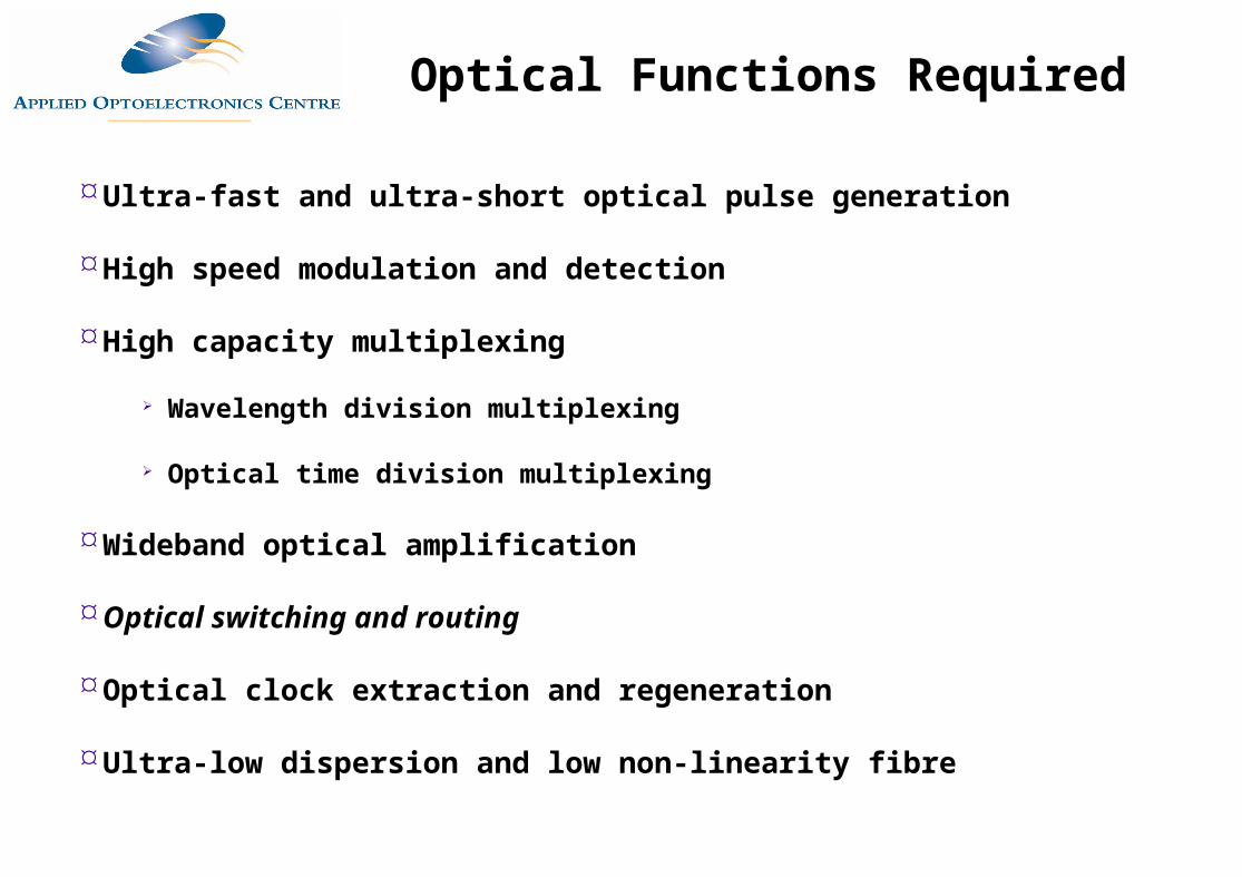
Ultra-fast and ultra-short optical pulse generation
High speed modulation and detection
High capacity multiplexing
Wavelength division multiplexing
Optical time division multiplexing
Wideband optical amplification
Optical switching and routing
Optical clock extraction and regeneration
Ultra-low dispersion and low non-linearity fibre
Optical Functions Required
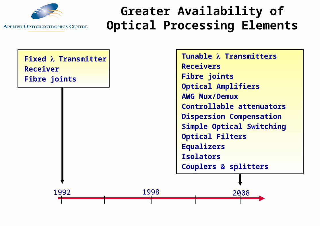
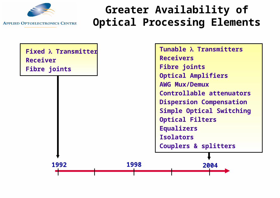
1992 20081998
Fixed TransmitterReceiverFibre joints
Tunable TransmittersReceiversFibre jointsOptical AmplifiersAWG Mux/DemuxControllable attenuatorsDispersion CompensationSimple Optical SwitchingOptical FiltersEqualizersIsolatorsCouplers & splitters
Greater Availability of Optical Processing Elements
Optical Add/DropMultiplexers
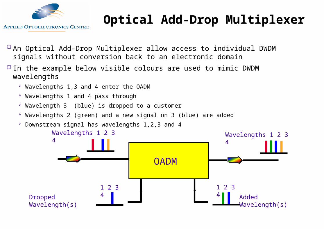
An Optical Add-Drop Multiplexer allow access to individual DWDM signals without conversion back to an electronic domain
In the example below visible colours are used to mimic DWDM wavelengths Wavelengths 1,3 and 4 enter the OADM Wavelengths 1 and 4 pass through Wavelength 3 (blue) is dropped to a customer Wavelengths 2 (green) and a new signal on 3 (blue) are added Downstream signal has wavelengths 1,2,3 and 4
Wavelengths 1 2 3 4
1 2 3 41 2 3 4
Wavelengths 1 2 3 4
OADM
Dropped Wavelength(s) Added Wavelength(s)
Optical Add-Drop Multiplexer
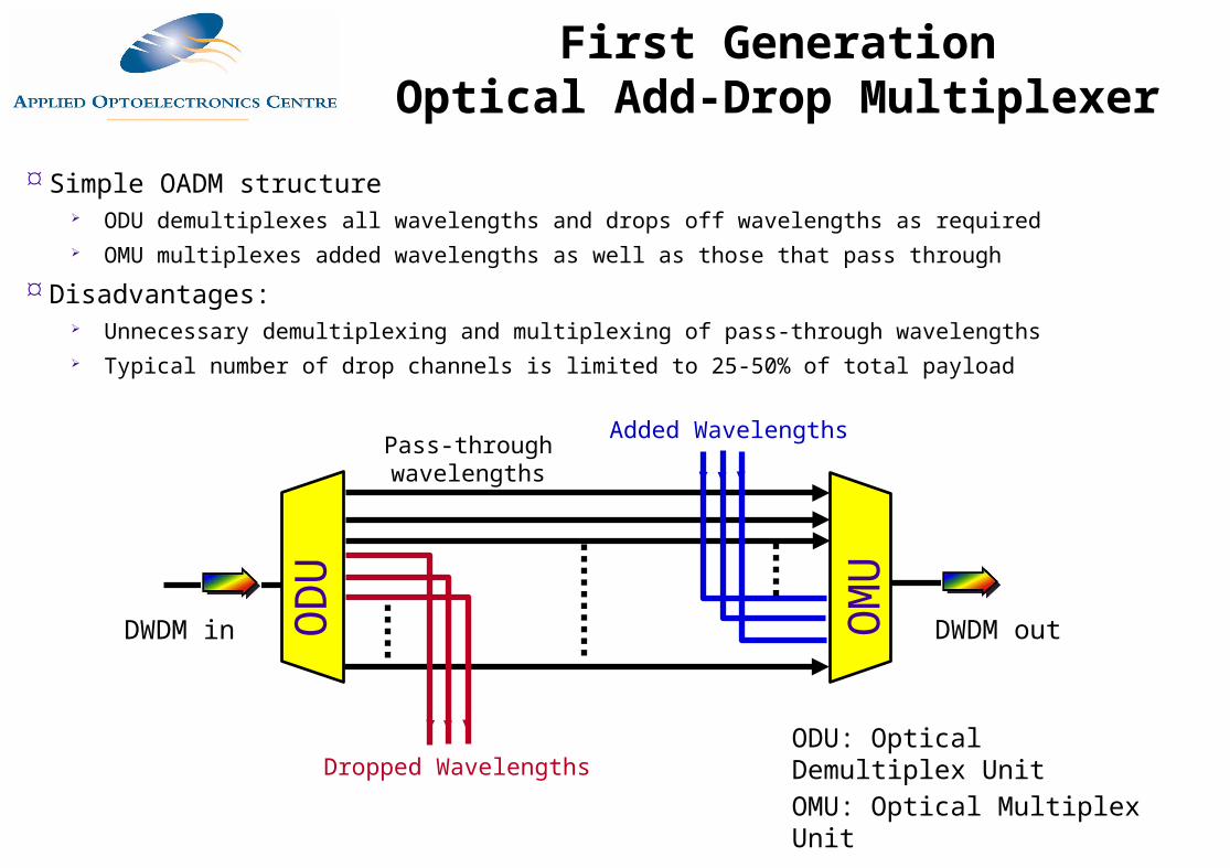
Simple OADM structure ODU demultiplexes all wavelengths and drops off wavelengths as required OMU multiplexes added wavelengths as well as those that pass through
Disadvantages: Unnecessary demultiplexing and multiplexing of pass-through wavelengths Typical number of drop channels is limited to 25-50% of total payload
OD
U
OM
U
ODU: Optical Demultiplex UnitOMU: Optical Multiplex UnitDropped Wavelengths
Added WavelengthsPass-through wavelengths
DWDM outDWDM in
First GenerationOptical Add-Drop Multiplexer
Source: Master 7_7
OADM
OADM OADM
OADM
Wavelengths 1 2 3 4
1 2 3 41 2 3 4
1 2 3 4
Node
A
Node
D
Node
B
Node
C
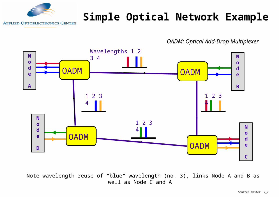
Note wavelength reuse of "blue" wavelength (no. 3), links Node A and B as well as Node C and A
OADM: Optical Add-Drop Multiplexer
Simple Optical Network Example
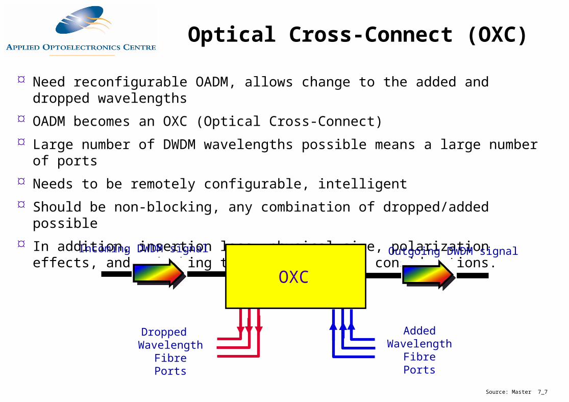
Need reconfigurable OADM, allows change to the added and dropped wavelengths
OADM becomes an OXC (Optical Cross-Connect)
Large number of DWDM wavelengths possible means a large number of ports
Needs to be remotely configurable, intelligent
Should be non-blocking, any combination of dropped/added possible
In addition, insertion loss, physical size, polarization effects, and switching times are critical considerations.
Source: Master 7_7
Incoming DWDM signal
Dropped Wavelength Fibre Ports
Outgoing DWDM signal
Added Wavelength Fibre Ports
OXC
Optical Cross-Connect (OXC)
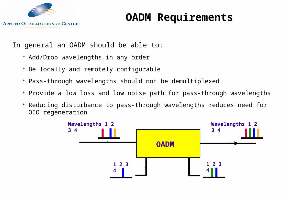
In general an OADM should be able to:
Add/Drop wavelengths in any order
Be locally and remotely configurable
Pass-through wavelengths should not be demultiplexed
Provide a low loss and low noise path for pass-through wavelengths
Reducing disturbance to pass-through wavelengths reduces need for OEO regeneration
Wavelengths 1 2 3 4
1 2 3 41 2 3 4
Wavelengths 1 2 3 4
OADM
OADM Requirements
1
3
2
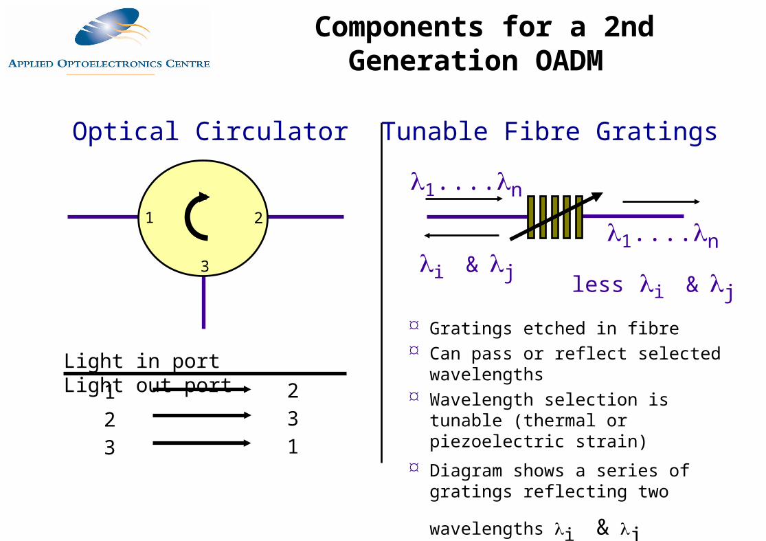
Light in port Light out port
123
231
Optical Circulator Tunable Fibre Gratings
1....n
1....n
less i & j i & j
Gratings etched in fibre Can pass or reflect selected
wavelengths Wavelength selection is tunable (thermal
or piezoelectric strain)
Diagram shows a series of gratings
reflecting two wavelengths i & j
Components for a 2nd Generation OADM
1
3
2 1
3
2
Demux Mux
Drop Wavelengths Add Wavelengths
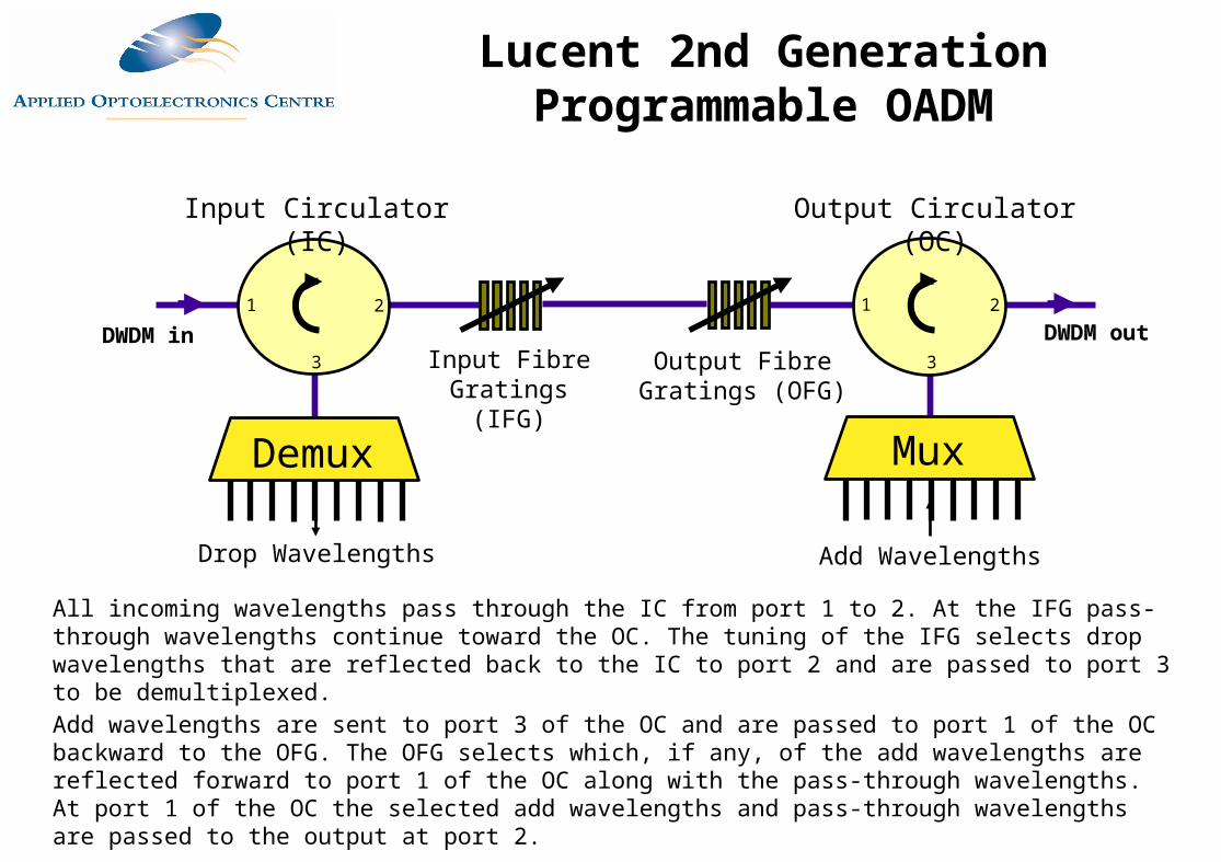
Input Circulator (IC) Output Circulator (OC)
Input Fibre Gratings (IFG)
Output Fibre Gratings (OFG)
All incoming wavelengths pass through the IC from port 1 to 2. At the IFG pass-through wavelengths continue toward the OC. The tuning of the IFG selects drop wavelengths that are reflected back to the IC to port 2 and are passed to port 3 to be demultiplexed. Add wavelengths are sent to port 3 of the OC and are passed to port 1 of the OC backward to the OFG. The OFG selects which, if any, of the add wavelengths are reflected forward to port 1 of the OC along with the pass-through wavelengths. At port 1 of the OC the selected add wavelengths and pass-through wavelengths are passed to the output at port 2.
DWDM outDWDM in
Lucent 2nd Generation Programmable OADM
Sample Optical Networks
Source: Master 7_7
MultiWave™ Metro is a Dense Wave Division Multiplexing (DWDM) system for use in metropolitan ring applications.
The MultiWave Metro system consists of Optical Add/Drop Multiplexer (OADM) nodes connected together on a two fiber ring.
It provides up to 24 duplex channels over a single fibre pair, allowing this single fibre pair to carry up to 120 Gb/s.
ITU Compliant Channel Plan: MultiWave Metro uses 200 GHz channel spacing as specified in ITU G.692.
Uses Standard fibre: MultiWave Metro operates on standard single mode fibre.
Ciena MultiWave Metro System (I)
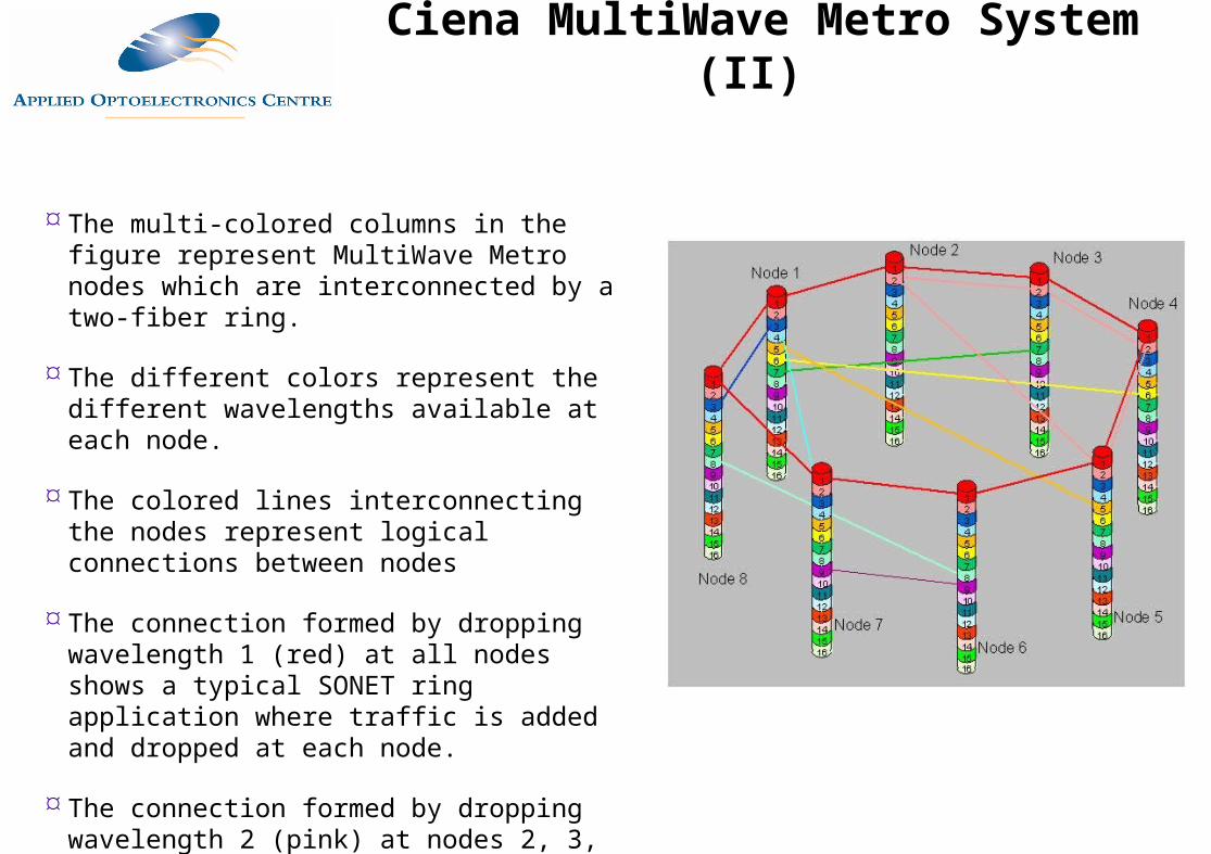
The multi-colored columns in the figure represent MultiWave Metro nodes which are interconnected by a two-fiber ring.
The different colors represent the different wavelengths available at each node.
The colored lines interconnecting the nodes represent logical connections between nodes
The connection formed by dropping wavelength 1 (red) at all nodes shows a typical SONET ring application where traffic is added and dropped at each node.
The connection formed by dropping wavelength 2 (pink) at nodes 2, 3, 4, and 5 shows how a private SONET ring might be implemented
Ciena MultiWave Metro System (II)
Protection and Restoration in Optical
Networks

Amplifier Noise
Optical Networks and Noise
OADM
Ring
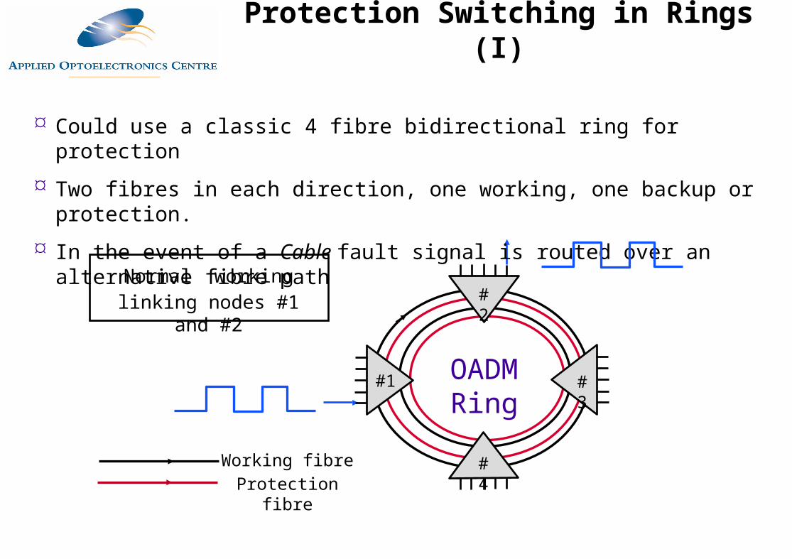
Could use a classic 4 fibre bidirectional ring for protection
Two fibres in each direction, one working, one backup or protection.
In the event of a Cable fault signal is routed over an alternative fibre path
Working fibreProtection fibre
Normal workinglinking nodes #1 and #2
#1
#2
#3
#4
Protection Switching in Rings (I)
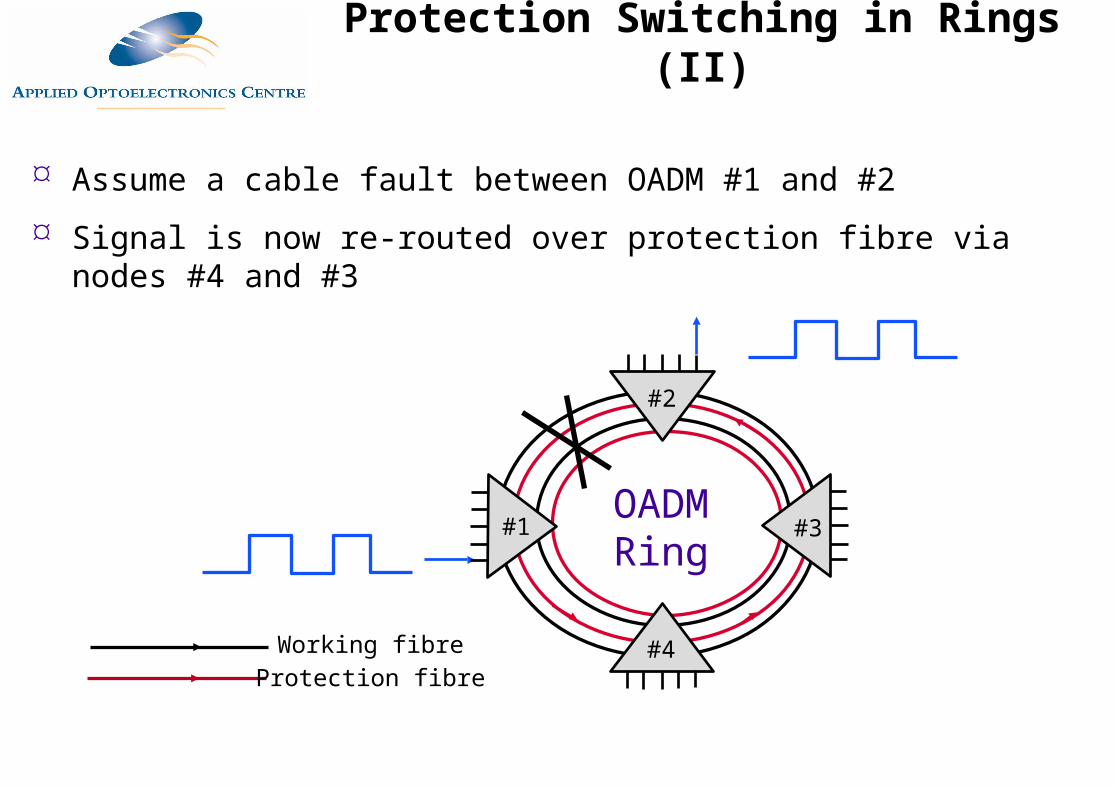
Assume a cable fault between OADM #1 and #2
Signal is now re-routed over protection fibre via nodes #4 and #3
OADM Ring
#1
#2
#3
#4Working fibreProtection fibre
Protection Switching in Rings (II)
Three important issues arise in ring switching OADMs for protection:
Wavelength reuse may mean a protection path is unavailable under certain conditions
Signal quality may mean long protection paths are unworkable
Mechanical switching reliability?
Protection Switching Issues in Optical Networks

OADM
Ring
Same wavelength is used twice:
Signal A uses node #1 to #2
Signal B uses node #3 to #4
No problem in the no fault state
#1
#2
#3
#4
Working fibreProtection fibre
Signal A
Signal A
Signal B
Signal B
Wavelength Reuse Issues (I)
OADM
Ring
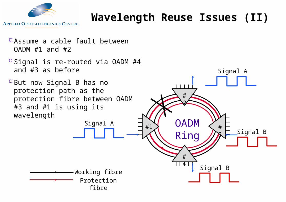
Assume a cable fault between OADM #1 and #2
Signal is re-routed via OADM #4 and #3 as before
But now Signal B has no protection path as the protection fibre between OADM #3 and #1 is using its wavelength
#1
#2
#3
#4
Working fibreProtection fibre
Signal A
Signal A
Signal B
Signal B
Wavelength Reuse Issues (II)
Maintaining signal quality is a key issue, even without protection switching
Protection switching makes signal quality even more difficult
In SDH rings full regeneration takes place at ADMs but in an OADM this not so
An optical wavelength transporting an SDH STM-N may pass through a number of amplifiers, fibre segments etc..
Signal may progressively deteriorate due to amplifier noise, crosstalk, dispersion etc..
Signal Quality Issues in OADM Rings
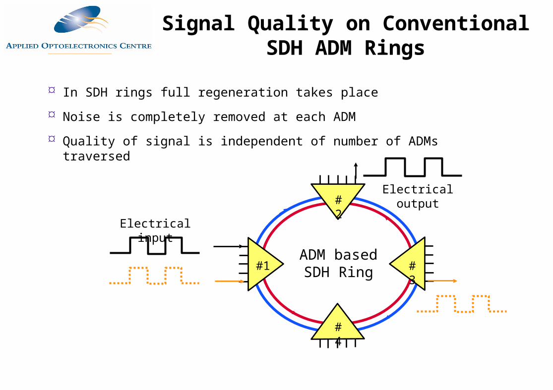
In SDH rings full regeneration takes place
Noise is completely removed at each ADM
Quality of signal is independent of number of ADMs traversed
ADM based SDH Ring
Electrical input
Electrical output
#1
#2
#3
#4
Signal Quality on Conventional SDH ADM Rings
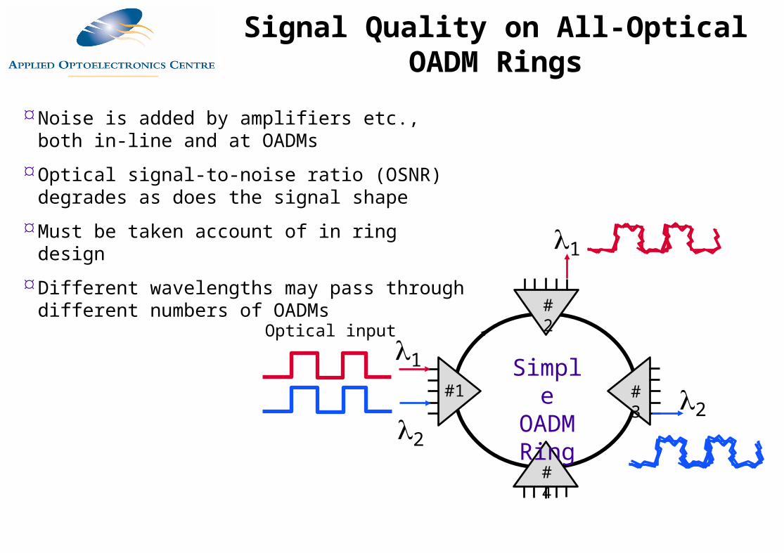
Noise is added by amplifiers etc., both in-line and at OADMs
Optical signal-to-noise ratio (OSNR) degrades as does the signal shape
Must be taken account of in ring design
Different wavelengths may pass through different numbers of OADMs
Simple OADM Ring
1
1
2
2
Optical input
#1
#2
#3
#4
Signal Quality on All-Optical OADM Rings
OADM
Ring
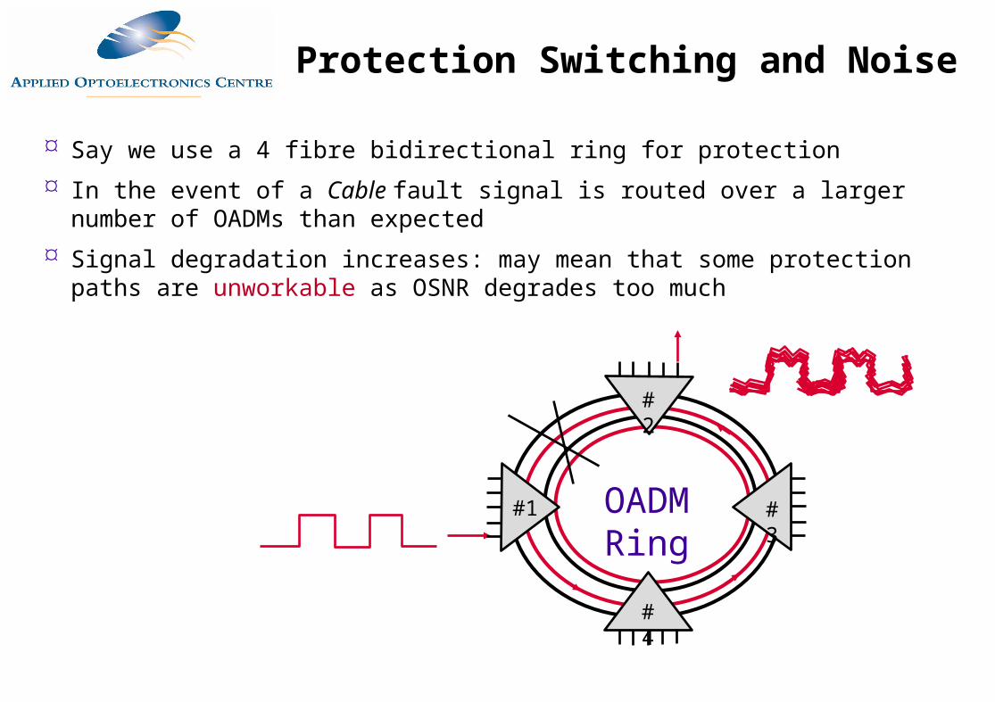
Say we use a 4 fibre bidirectional ring for protection
In the event of a Cable fault signal is routed over a larger number of OADMs than expected
Signal degradation increases: may mean that some protection paths are unworkable as OSNR degrades too much
#1
#2
#3
#4
Protection Switching and Noise
Optical networks are close to realisation
Routing and switching technologies need to be improved
Several WDM based optical network topologies proposed
By 2010 it is estimated that most Telecoms networks will have moved to an optical core
1992 20041998
Fixed TransmitterReceiverFibre joints
Tunable TransmittersReceiversFibre jointsOptical AmplifiersAWG Mux/DemuxControllable attenuatorsDispersion CompensationSimple Optical SwitchingOptical FiltersEqualizersIsolatorsCouplers & splitters
Greater Availability of Optical Processing Elements
All-Optical Wavelength Conversion
1550 nmSDH
C band signal
C band T/X
SDH R/X Electrical
levels
1550 nmSDH
C band signal
SDHT/X
C Band R/XElectrical
levels
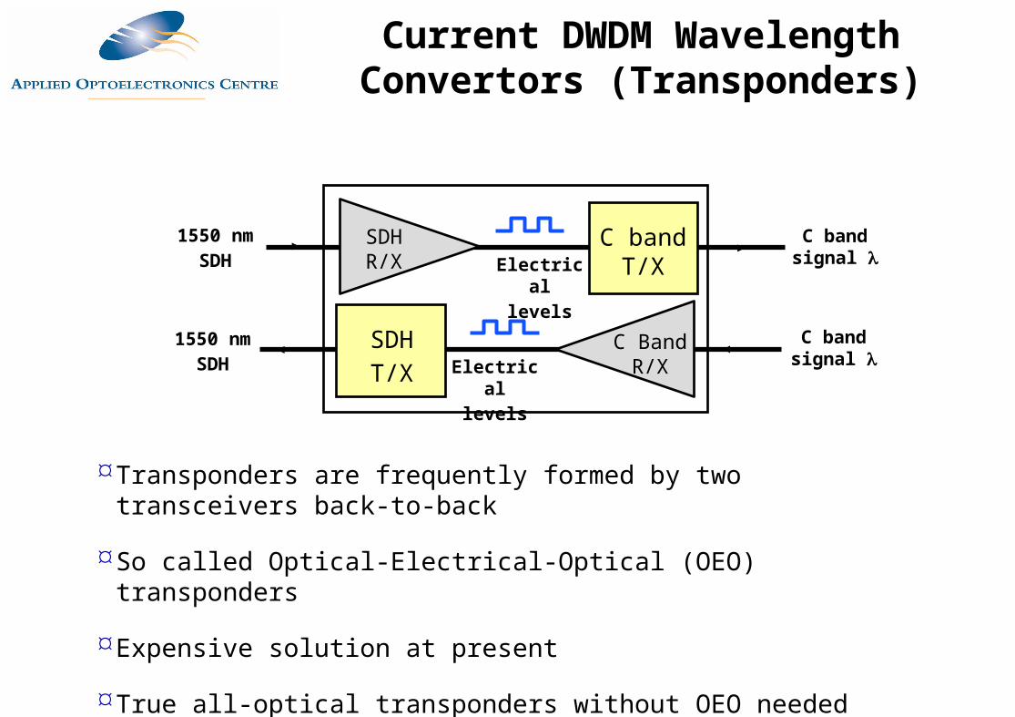
Transponders are frequently formed by two transceivers back-to-back
So called Optical-Electrical-Optical (OEO) transponders
Expensive solution at present
True all-optical transponders without OEO needed
Current DWDM Wavelength Convertors (Transponders)
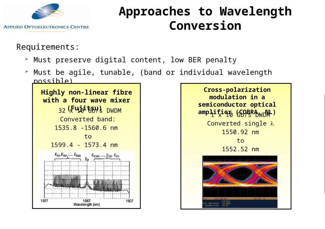
Requirements: Must preserve digital content, low BER penalty
Must be agile, tunable, (band or individual wavelength possible)
Highly non-linear fibre with a four wave mixer (Fujitsu)
32 x 10 Gb/s DWDMConverted band:
1535.8 -1560.6 nm to
1599.4 - 1573.4 nm
Cross-polarization modulation in a semiconductor optical
amplifier (COBRA, NL)
1 x 10 Gb/s DWDMConverted single
1550.92 nmto
1552.52 nm
Approaches to Wavelength Conversion
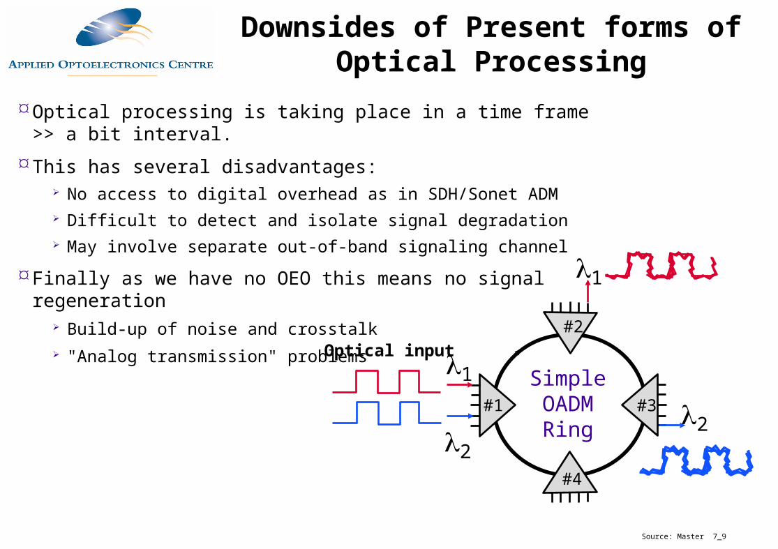
Optical processing is taking place in a time frame >> a bit interval.
This has several disadvantages: No access to digital overhead as in SDH/Sonet ADM Difficult to detect and isolate signal degradation May involve separate out-of-band signaling channel
Finally as we have no OEO this means no signal regeneration Build-up of noise and crosstalk "Analog transmission" problems
Simple OADM Ring
1
1
2
2
Optical input
#1
#2
#3
#4
Downsides of Present forms of Optical Processing
Source: Master 7_9
All-Optical Regeneration
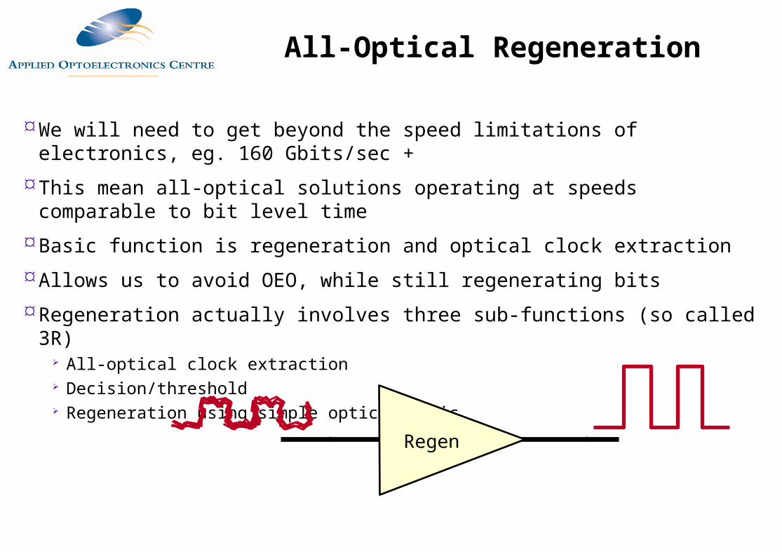
We will need to get beyond the speed limitations of electronics, eg. 160 Gbits/sec +
This mean all-optical solutions operating at speeds comparable to bit level time
Basic function is regeneration and optical clock extraction
Allows us to avoid OEO, while still regenerating bits
Regeneration actually involves three sub-functions (so called 3R) All-optical clock extraction Decision/threshold Regeneration using simple optical logic
Regen
All-Optical Regeneration
SPAN 1.00 GHz Center 0.50 GHz
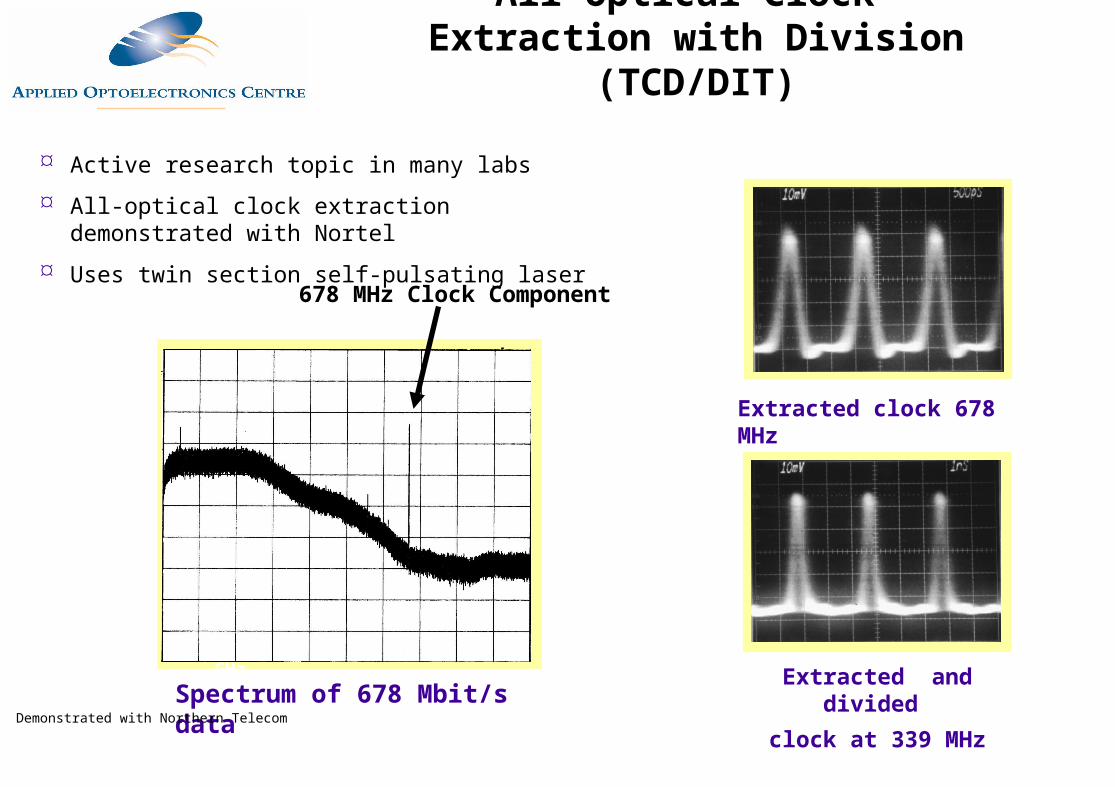
678 MHz Clock Component
Spectrum of 678 Mbit/s data
Extracted clock 678 MHz
Extracted and divided
clock at 339 MHz
500 ps
/div
1 ns
/div
Demonstrated with Northern Telecom
Active research topic in many labs
All-optical clock extraction demonstrated with Nortel
Uses twin section self-pulsating laser
All-Optical Clock Extraction with Division (TCD/DIT)
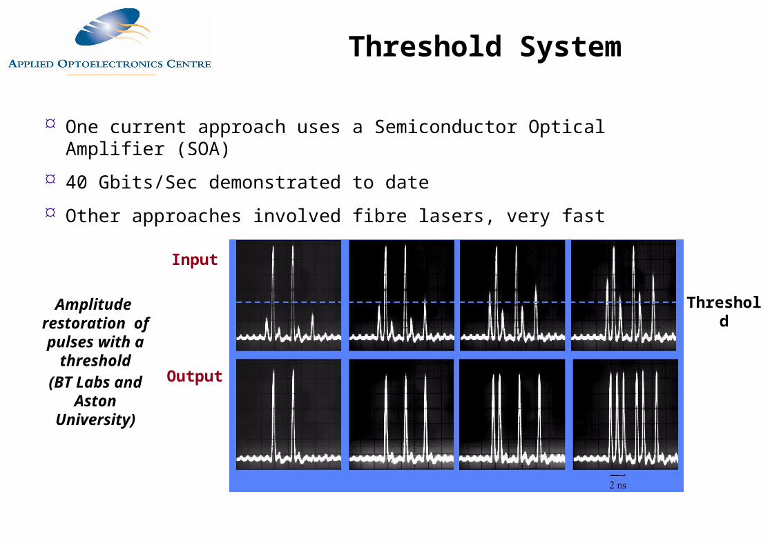
One current approach uses a Semiconductor Optical Amplifier (SOA)
40 Gbits/Sec demonstrated to date
Other approaches involved fibre lasers, very fast
Output
Input
Amplitude restoration of pulses with a
threshold(BT Labs and
Aston University)
Threshold
Threshold System