Optical Needle Stroke Detection System...
62
Optical Needle Stroke Detection System OptiStrokeT Manual P/N 213 958 B – English – Issued 12/03 NORDSON ENGINEERING GMBH D LÜNEBURG D GERMANY
Transcript of Optical Needle Stroke Detection System...

Optical Needle Stroke Detection SystemOptiStroke �
Manual P/N 213 958 B– English –
Issued 12/03
NORDSON ENGINEERING GMBH � LÜNEBURG � GERMANY

P/N 213958B � 2003 Nordson CorporationOptiStroke
NOTEThis manual is for products with the following P/N:
466 111
466 541
466 542
466 543
Order numberP/N = Order number for Nordson products
NoticeThis is a Nordson Corporation publication which is protected by copyright. Original copyright date
2002.No part of this document may be photocopied, reproduced, or translated to another language without
the prior written consent of Nordson Corporation. The information contained in this publication issubject to change without notice.
2003 All rights reserved.
TrademarksAccuJet, AeroCharge, AquaGuard, Asymtek, Automove, Autotech, Baitgun, Blue Box, CanWorks, Century, CF, Clean Coat, CleanSleeve, CleanSpray,Control Coat, CoolWave, Cross-Cut, Cyclo-Kinetic, Dispensejet, DispenseMate, Durafiber, Durasystem, Easy Coat, Easymove Plus, Econo-Coat, EFD,ETI, Excel 2000, FlexiCoat, Flexi-Spray, Flex-O-Coat, Flow Sentry, Fluidmove, FoamMelt, FoamMix, Heli-flow, Helix, Horizon, Hot Shot, Isocoil, Isocore,Iso-Flo, JR, KB30, Kinetix, Little Squirt, Magnastatic, MEG, Meltex, Microcoat, Micromark, MicroSet, Millenium, Mini Squirt, Moist-Cure, Mountaingate,MultiScan, Nordson, OmniScan, OptiMix, Package of Values, Patternview, PermaFlo, Plasmod, PluraFoam, Porous Coat, PowderGrid, Powderware,Prism, ProBlue, Pro-Flo, ProLink, Pro-Meter, Pro-Stream, RBX, Rhino, Saturn, SC5, S. design stylized, Seal Sentry, Select Charge, Select Coat, SelectCure, Slautterback, Smart-Coat, Solder Plus, Spectrum, Speed-Coat, Spraymelt, Spray Squirt, Super Squirt, Sure Coat, Tela-Therm, Tracking Plus, Trends,Tribomatic, Ultrasaver, UniScan, UpTime, Veritec, VersaBlue, Versa-Coat, Versa-Screen, Versa-Spray, Walcom, Watermark, When you expect more.are registered trademarks – � – of Nordson Corporation.
AeroDeck, AeroWash, Apogee, ATS, Auto-Flo, AutoScan, BetterBook, CanNeck, Chameleon, Check Mate, ColorMax, Controlled Fiberization, ControlWeave, CPX, Dry Cure, DuraBlue, Dura-Coat, DuraPail, Dura-Screen, Easy Clean, Eclipse, EcoDry, e.DOT, E-Nordson, Equi=Bead, ESP, e Stylized,Fillmaster, Fill Sentry, Gluie, HDLV, iControl, iFlow, Ink-Dot, iON, Iso-Flex, iTrend, KVLP, Lacquer Cure, March, Maxima, MicroFin, MicroMax, Minimeter,Multifil, OptiStroke, Origin, PatternPro, PluraMix, Powder Pilot, Powercure, Primarc, Printplus, Process Sentry, Pulse Spray, PurTech, Ready Coat,Scoreguard, Select Series, Sensomatic, Shaftshield, SheetAire, Spectral, Spectronic, Speedking, Spray Works, Summit, SureBead, Sure Brand, SureClean, Sure-Max, Swirl Coat, Tempus, ThruWave, Trade Plus, Trak, Ultrasmart, Universal, Vantage, Viper, Vista, Web Cure, 2 Rings (Design) aretrademarks – � – of Nordson Corporation.
Designations and trademarks stated in this document may be brands that, when used by third parties for their own purposes, could lead to violation of the owners’ rights.

Table of Contents I
P/N 213958B� 2003 Nordson Corporation OptiStroke
Table of Contents
Safety Instructions 1. . . . . . . . . . . . . . . . . . . . . . . . . . . . . . . . . . . . . .
Introduction 1. . . . . . . . . . . . . . . . . . . . . . . . . . . . . . . . . . . . . . . . . . . . . Intended Use 1. . . . . . . . . . . . . . . . . . . . . . . . . . . . . . . . . . . . . . . . . . . .
Area of Use (EMC) 1. . . . . . . . . . . . . . . . . . . . . . . . . . . . . . . . . . . . . Operating Restrictions 1. . . . . . . . . . . . . . . . . . . . . . . . . . . . . . . .
Unintended Use – Examples 1. . . . . . . . . . . . . . . . . . . . . . . . . . . . Residual Risks 1. . . . . . . . . . . . . . . . . . . . . . . . . . . . . . . . . . . . . . . . . . . Function 2. . . . . . . . . . . . . . . . . . . . . . . . . . . . . . . . . . . . . . . . . . . . . . . . .
System Environment 2. . . . . . . . . . . . . . . . . . . . . . . . . . . . . . . . . . . System Configuration Master – Slave Mode 3. . . . . . . . . . . . . . . . . . Serial Interface Data 3. . . . . . . . . . . . . . . . . . . . . . . . . . . . . . . . . . . . . . Alarm Outputs 4. . . . . . . . . . . . . . . . . . . . . . . . . . . . . . . . . . . . . . . . . . .
Function Diagram 5. . . . . . . . . . . . . . . . . . . . . . . . . . . . . . . . . . . . . . ID Plate 6. . . . . . . . . . . . . . . . . . . . . . . . . . . . . . . . . . . . . . . . . . . . . . . . . Definition of Terms 6. . . . . . . . . . . . . . . . . . . . . . . . . . . . . . . . . . . . . . . . User Interface of the Software 6. . . . . . . . . . . . . . . . . . . . . . . . . . . . . .
Overview 7. . . . . . . . . . . . . . . . . . . . . . . . . . . . . . . . . . . . . . . . . . . . . Saving 8. . . . . . . . . . . . . . . . . . . . . . . . . . . . . . . . . . . . . . . . . . . . . . . . Scan Channel 9. . . . . . . . . . . . . . . . . . . . . . . . . . . . . . . . . . . . . . . . . Module Type 9. . . . . . . . . . . . . . . . . . . . . . . . . . . . . . . . . . . . . . . . . . Setup 10. . . . . . . . . . . . . . . . . . . . . . . . . . . . . . . . . . . . . . . . . . . . . . . . .
Threshold ON in % 10. . . . . . . . . . . . . . . . . . . . . . . . . . . . . . . . . . . Threshold OFF in % 10. . . . . . . . . . . . . . . . . . . . . . . . . . . . . . . . . . Missing Needle Stroke Detection 11. . . . . . . . . . . . . . . . . . . . . . Auto Range / Scan Time 12. . . . . . . . . . . . . . . . . . . . . . . . . . . . . . Offset 13. . . . . . . . . . . . . . . . . . . . . . . . . . . . . . . . . . . . . . . . . . . . . . Threshold Missing Needle Stroke 14. . . . . . . . . . . . . . . . . . . . . . Rejection (Kick Out) Alarm in ms 15. . . . . . . . . . . . . . . . . . . . . . . Default Settings 16. . . . . . . . . . . . . . . . . . . . . . . . . . . . . . . . . . . . . Extended Data Log with Status Bytes 16. . . . . . . . . . . . . . . . . . Display Status Bytes 17. . . . . . . . . . . . . . . . . . . . . . . . . . . . . . . . .
Histogram 18. . . . . . . . . . . . . . . . . . . . . . . . . . . . . . . . . . . . . . . . . . . . . Languages 19. . . . . . . . . . . . . . . . . . . . . . . . . . . . . . . . . . . . . . . . . . . . RS 232 19. . . . . . . . . . . . . . . . . . . . . . . . . . . . . . . . . . . . . . . . . . . . . . . Graphic Mode 20. . . . . . . . . . . . . . . . . . . . . . . . . . . . . . . . . . . . . . . . .
Table View 20. . . . . . . . . . . . . . . . . . . . . . . . . . . . . . . . . . . . . . . . . . Histogram View of Table Values 21. . . . . . . . . . . . . . . . . . . . . . .
Table Mode 22. . . . . . . . . . . . . . . . . . . . . . . . . . . . . . . . . . . . . . . . . . . Table View 22. . . . . . . . . . . . . . . . . . . . . . . . . . . . . . . . . . . . . . . . . . Histogram View 23. . . . . . . . . . . . . . . . . . . . . . . . . . . . . . . . . . . . .

Table of ContentsII
P/N 213958B � 2003 Nordson CorporationOptiStroke
Installation 24. . . . . . . . . . . . . . . . . . . . . . . . . . . . . . . . . . . . . . . . . . . . . . Transport 24. . . . . . . . . . . . . . . . . . . . . . . . . . . . . . . . . . . . . . . . . . . . . . . . Unpacking 24. . . . . . . . . . . . . . . . . . . . . . . . . . . . . . . . . . . . . . . . . . . . . . . Installing 24. . . . . . . . . . . . . . . . . . . . . . . . . . . . . . . . . . . . . . . . . . . . . . . . Removal 24. . . . . . . . . . . . . . . . . . . . . . . . . . . . . . . . . . . . . . . . . . . . . . . . Storage 25. . . . . . . . . . . . . . . . . . . . . . . . . . . . . . . . . . . . . . . . . . . . . . . . . Disposal 25. . . . . . . . . . . . . . . . . . . . . . . . . . . . . . . . . . . . . . . . . . . . . . . . . Addition or Modification of Control Modules 25. . . . . . . . . . . . . . . . . .
Adding a Module Cap for Suction Needle Control Modules 25. . Replacing Suction Needle Control Modules 25. . . . . . . . . . . . . . . . Replacing Universal Control Modules 26. . . . . . . . . . . . . . . . . . . . .
Connecting Optical Fiber Cable 26. . . . . . . . . . . . . . . . . . . . . . . . . . . . Electrical Connections 27. . . . . . . . . . . . . . . . . . . . . . . . . . . . . . . . . . . .
Establishing Master – Slave Configuration 28. . . . . . . . . . . . . . . . . Connecting an External Control Unit 28. . . . . . . . . . . . . . . . . . . . . . Connecting a PC 29. . . . . . . . . . . . . . . . . . . . . . . . . . . . . . . . . . . . . . .
Starting up OptiStroke with the PC 29. . . . . . . . . . . . . . . . . . . . .
Operation 30. . . . . . . . . . . . . . . . . . . . . . . . . . . . . . . . . . . . . . . . . . . . . . . Operation when Connected to an External Control Unit 30. . . . . . . . Operation with the PC 30. . . . . . . . . . . . . . . . . . . . . . . . . . . . . . . . . . . . .
Maintenance 32. . . . . . . . . . . . . . . . . . . . . . . . . . . . . . . . . . . . . . . . . . . . OptiStroke 32. . . . . . . . . . . . . . . . . . . . . . . . . . . . . . . . . . . . . . . . . . . . Optical fiber cables 32. . . . . . . . . . . . . . . . . . . . . . . . . . . . . . . . . . . . .
Troubleshooting 33. . . . . . . . . . . . . . . . . . . . . . . . . . . . . . . . . . . . . . . . . Transmitted Light LEDs 33. . . . . . . . . . . . . . . . . . . . . . . . . . . . . . . . . . . Indicator Beacon LEDs 34. . . . . . . . . . . . . . . . . . . . . . . . . . . . . . . . . . . . Trigger LEDs 34. . . . . . . . . . . . . . . . . . . . . . . . . . . . . . . . . . . . . . . . . . . . . Troubleshooting Tables 35. . . . . . . . . . . . . . . . . . . . . . . . . . . . . . . . . . . .
Spare Parts 39. . . . . . . . . . . . . . . . . . . . . . . . . . . . . . . . . . . . . . . . . . . . . Control Modules 39. . . . . . . . . . . . . . . . . . . . . . . . . . . . . . . . . . . . . . . Optical Fiber Cables 39. . . . . . . . . . . . . . . . . . . . . . . . . . . . . . . . . . . . Accessories 39. . . . . . . . . . . . . . . . . . . . . . . . . . . . . . . . . . . . . . . . . . .
Technical Data 40. . . . . . . . . . . . . . . . . . . . . . . . . . . . . . . . . . . . . . . . . . General Data 40. . . . . . . . . . . . . . . . . . . . . . . . . . . . . . . . . . . . . . . . . . . . Connecting Sockets 41. . . . . . . . . . . . . . . . . . . . . . . . . . . . . . . . . . . . . . Pin Allocation 42. . . . . . . . . . . . . . . . . . . . . . . . . . . . . . . . . . . . . . . . . . . .
Connecting Socket Data (Serial Interface Data) 42. . . . . . . . . . . . Connecting Socket Prog. (Serial Interface Program) 42. . . . . . . . Connecting Socket CAN 1 42. . . . . . . . . . . . . . . . . . . . . . . . . . . . . . . Connecting Socket CAN 2 42. . . . . . . . . . . . . . . . . . . . . . . . . . . . . . .
Table of Contents III
P/N 213958B� 2003 Nordson Corporation OptiStroke
Appendix 43. . . . . . . . . . . . . . . . . . . . . . . . . . . . . . . . . . . . . . . . . . . . . . . DIP Switch Settings 43. . . . . . . . . . . . . . . . . . . . . . . . . . . . . . . . . . . . . . .
Master Unit 43. . . . . . . . . . . . . . . . . . . . . . . . . . . . . . . . . . . . . . . . . . . . Slave Unit 43. . . . . . . . . . . . . . . . . . . . . . . . . . . . . . . . . . . . . . . . . . . . .
Transmission Log 45. . . . . . . . . . . . . . . . . . . . . . . . . . . . . . . . . . . . . . . . Factory Settings (Without Status Bytes) 45. . . . . . . . . . . . . . . . . . . Settings (With Status Bytes) 46. . . . . . . . . . . . . . . . . . . . . . . . . . . . .
Status Bytes 47. . . . . . . . . . . . . . . . . . . . . . . . . . . . . . . . . . . . . . . . . . . . . Status Word # 1 – Bit 0 to 7 47. . . . . . . . . . . . . . . . . . . . . . . . . . . . . Status Word # 1 – Bit 8 to 15 48. . . . . . . . . . . . . . . . . . . . . . . . . . . . Status Word # 2 – Bit 0 to 7 49. . . . . . . . . . . . . . . . . . . . . . . . . . . . . Status Word # 2 – Bit 8 to 15 50. . . . . . . . . . . . . . . . . . . . . . . . . . . . Evaluation of Status Bytes – Example 1 51. . . . . . . . . . . . . . . . . . . Evaluation of Status Bytes – Example 2 52. . . . . . . . . . . . . . . . . . .
Simplified Phase Model 53. . . . . . . . . . . . . . . . . . . . . . . . . . . . . . . . . . . OptiStroke Board 54. . . . . . . . . . . . . . . . . . . . . . . . . . . . . . . . . . . . . . . . . Extended Missing Needle Stroke Detection 55. . . . . . . . . . . . . . . . . .
Example 1: Normal Mode 55. . . . . . . . . . . . . . . . . . . . . . . . . . . . . . . Example 2: Operation with Extended Missing Needle Stroke Detection 55. .

Table of ContentsIV
P/N 213958B � 2003 Nordson CorporationOptiStroke

Optical needle stroke detection system 1
P/N 213958B� 2003 Nordson Corporation OptiStroke
Safety InstructionsWARNING: Observe and follow all safety instructions, the general safetyinstructions included as a separate document, as well as the specific safetyinstructions in all other related documentation.
Introduction
Intended UseThe optical needle stroke detection system – hereafter also referred to asOptiStroke – may be used only to evaluate and process optical signalstriggered by the movement of the needles in application control modules.Suitable optical fiber cables must be connected for this purpose (Refer toInstallation).
Area of Use (EMC)This unit is intended for use in industrial applications.
Operating Restrictions
When operated in residential or commercial areas, the unit may causeinterference in other electrical units, e.g. radios.
Unintended Use – ExamplesOptiStroke may not be used under the following conditions:
� In defective condition
� When the unit lid is open
� When changes or modifications have been made by the customer
� When the values stated under Technical Data are not complied with.
Residual RisksNordson knows of no residual risks.

2 Optical needle stroke detection system
P/N 213958B � 2003 Nordson CorporationOptiStroke
FunctionOptical fiber cables are attached to each control module of an applicationhead. The movement of the needles is compiled and transmitted toOptiStroke as an optical signal. Each control module is connected to exactlyone measuring channel in the OptiStroke.
OptiStroke converts the optical signals to digital signals (switching times[ms]). This data is made available via the serial interface Data for furtherprocessing by a PLC or another control unit to form a control circuit.
A PC may be connected to the serial interface Prog. (program). A (MicrosoftWindows based) program offers comprehensive data analysis on the PC.
System Environment
003069
Pattern controller
Data log
Parameterizationand analysis
software
Interface Data
Interface Prog.
CAN bus: Slave 1/2,channel 5 -12
General alarm outputProduct rejection
(kick out)
Max. 4 optical fiber cables =max. 4 measuring channels
4x v
alve
trig
gerin
g
Speed Coat�
OptiStroke
PLC
Fig. 1

Optical needle stroke detection system 3
P/N 213958B� 2003 Nordson Corporation OptiStroke
System Configuration Master – Slave ModeUp to three OptiStroke units can be interconnected in master – slave mode.This permits monitoring and control of up to 12 channels (12 controlmodules).
NOTE: The external control unit and the PC must always be connected tothe master unit.
The following applies:
Master unit Max. 4 channels can be compiled
Master + slave unit Max. 8 channels can be compiled
Master + slave + slave unit Max. 12 channels can be compiled
Serial Interface DataIn normal mode, OptiStroke is connected to an external control unit. Thefollowing data is transmitted to the external control unit via the serialinterface Data.
� Switchon and switchoff time
� Transmitted light
� Missing needle strokes
� Unit status bytes.
The interface transmits all data from all channels every second. Thetransmitted switchon and switchoff times are averages of the last ninemeasurements.
NOTE: If during a one second transmission interval even one error occurs,the control unit is informed of the error as a switching time 0,00 / 0,00 s(missing needle stroke).
This guarantees compiling of a single error via the interface.

4 Optical needle stroke detection system
P/N 213958B � 2003 Nordson CorporationOptiStroke
Alarm OutputsSeveral alarm outputs ensure continuous detection of defective controlmodules. This enables realtime product rejection (lick out) when theapplication pattern is faulty.
� Kick-out alarm (duration: factory setting 50 ms)
Missing needle stroke of a control module
This error indication (voltage pulse) can be used to activate a mechanismfor product rejection.
� General alarm for all triggered measuring channels (duration: approx. 3 seconds)
Missing needle stroke of a control module
Measuring channels are triggered during initialization.
� Data log via the serial interface Data (data transfer once per second)
Missing needle stroke (switching times = 0.00 / 0.00 s)
The extended data log also contains status bit 26 (Refer to appendix).
Optical needle stroke detection system 5
P/N 213958B� 2003 Nordson Corporation OptiStroke
Function Diagram
Valve voltagecontrol module
24 V
0 V
Switchon time Switchoff time
Needle stroke OK Needle stroke missingNeedle strokecontrol module
Control module OPEN
Control module CLOSED
24 V
0 V
Product rejection bychannel
General alarmchannels 1 to 12
ON
ON
OFF
OFF
Approx. 3 seconds
1 to 100 ms
Data transmissionto control unit
Fig. 2 Function diagram of alarm outputs

R
P/N:S/N:FT:
�
6 Optical needle stroke detection system
P/N 213958B � 2003 Nordson CorporationOptiStroke
ID PlateThe ID plate displays the following information:
Nordson order number
Serial number
Production date (month/year)
Fig. 3
Definition of TermsThe terms missing needle stroke and needle stroke missing are used in theparameterization and analysis software. They mean the same thing. Whenapplicable, they are cited in the manual. Usually the term missing needlestroke is used.
User Interface of the SoftwareIf the entire material application process is to be analyzed and optimized,analysis and parameterization software is available for a PC. The softwaremust be installed on a PC. The PC must be connected to the correspondingserial interface Prog. on the OptiStroke.
The parameters for the measurements are entered with the aid of thesoftware. The courses of signals, switchon and switchoff times, randomorientation of the measured values and many other things can be displayedwith this software in graphic or table mode.
The analysis and parameterization software is based on the MicrosoftWindows operating system. The user must be familiar with this operatingsystem to be able to operate the program.
All functions can be selected and activated with the mouse. Measuring ofthe switchon and switchoff times is started with the Start key and stoppedwith the Stop key.

Optical needle stroke detection system 7
P/N 213958B� 2003 Nordson Corporation OptiStroke
Overview
System message
Amplification (ADC offset)
Transmitted light in %
Stroke signal level
Threshold missing needle stroke
Switchon time
Switchoff time
Switchon signal = red Switchoff signal = blue
Switchon time = intersection ofsignal and threshold
Switchoff time = intersection ofsignal and threshold
System message
Status bytes
Fig. 4
NOTE: In the graphic display, the needle stroke (0 ... 100%) is shown as afactor of measuring time (interval variable, in this case 0 ... 15 ms).

8 Optical needle stroke detection system
P/N 213958B � 2003 Nordson CorporationOptiStroke
User Interface of the Software (contd.)
SavingIn this menu the operator can choose whether or not to save the measureddata in a file. A checkmark next to the entry when preselection of counter,times will be saved in a text file enables the data from subsequentmeasurements to be saved.
Prerequisite: The desired number of measuring cycles (at least ten) must bepreselected under counter (Refer to Fig. 5).
If measurement is started manually, a selection box for entering path, dataname and data type appears. Measurement stops automatically when thepreselected measuring cycles have ended.
Fig. 5
NOTE: The number that can be selected under counter corresponds to thequantity of measurements to be performed. If 0 (zero) is selected, an infinitenumber of measurements is performed. Measurement is not stopped(logically 0 times).

Optical needle stroke detection system 9
P/N 213958B� 2003 Nordson Corporation OptiStroke
Scan ChannelThe desired measuring channel (control module) can be selected in thismenu.
Fig. 6
Module TypeThis menu displays the module types (= control module types) (preset viaDIP switches in OptiStroke) and firmware version of the processors for eachmeasuring channel.
Firmware version of the communication processor
Firmware version of the measurement processor
Fig. 7
NOTE: Control module type normal: Control module opens by movingdown (suction needle control module).
NOTE: Control module type inverse: Control module opens by moving up(universal control module).

10 Optical needle stroke detection system
P/N 213958B � 2003 Nordson CorporationOptiStroke
User Interface of the Software (contd.)
Setup
Threshold ON in %
The set threshold corresponds to the degree to which the needle is open,stated as a percent value, at which the switchon time is measured.
The intersection of the course of the switchon signal and the threshold is theswitchon time.
Fig. 8
Threshold OFF in %
The set threshold corresponds to the degree to which the needle is open,stated as a percent value, at which the switchoff time is measured.
The intersection of the course of the switchoff signal and the threshold is theswitchoff time.
Fig. 9

Optical needle stroke detection system 11
P/N 213958B� 2003 Nordson Corporation OptiStroke
Missing Needle Stroke DetectionExtended missing needle stroke detection can be activated in this menu.Factory setting: All software switches missing needle stroke detectionwithout offset adjustment are set to OFF. Changes are acknowledged bypressing OK.
Fig. 10
Extended missing needle stroke detection is a special feature that enablespossible errors to be recognized by long-term stroke changes.
NOTE: Nordson recommends that this feature not be used during normaloperation; it requires substantially more effort to operate (For moreinformation, refer to Appendix).

12 Optical needle stroke detection system
P/N 213958B � 2003 Nordson CorporationOptiStroke
User Interface of the Software (contd.)
Setup (contd.)
Auto Range / Scan Time
Fixed or automatically adapted scan times (measuring time intervals) canbe set in this menu for each channel.
The following scan times are possible: 5 / 7.5 / 10 / 15 / 20 / 30 / 40 / 50 / 75and 100 milliseconds.
NOTE: The fixed scan time must be larger than the anticipated switchingtimes of the control modules.
All software switches are factory set to the status auto. Changes areacknowledged by pressing OK.
Fig. 11

Optical needle stroke detection system 13
P/N 213958B� 2003 Nordson Corporation OptiStroke
OffsetAll switchon and switchoff times transmitted from the serial interface Datacan be assigned an offset value in this menu.
Example: The flight time of the material between when it leaves the nozzleand hits the substrate is an offset time. This flight time must be consideredwhen optimizing the application.
In every mode, the PC software shows only the actual switching times. Alloffsets are factory set to 0 milliseconds. Changes are acknowledged bypressing OK.
Fig. 12

14 Optical needle stroke detection system
P/N 213958B � 2003 Nordson CorporationOptiStroke
User Interface of the Software (contd.)
Setup (contd.)
Threshold Missing Needle Stroke
All threshold missing needle stroke values for channels 1 to 12 are enteredin this menu.
A mechanical needle stroke of 100 % corresponds to a stroke signal level of25 %. If the green stroke signal level is lower than the red threshold missingneedle stroke, the needle stroke is interpreted as a missing needle stroke.
All threshold missing needle stroke values are factory set to 5 %. Changesare acknowledged by pressing OK.
Stroke signal level
Threshold missing needle stroke
Fig. 13

Optical needle stroke detection system 15
P/N 213958B� 2003 Nordson Corporation OptiStroke
Rejection (Kick Out) Alarm in msThe duration of the product rejection alarm pulse for missing needle strokesis set in this menu.
The factory setting is 50 milliseconds. Changes are acknowledged bypressing OK.
Fig. 14

16 Optical needle stroke detection system
P/N 213958B � 2003 Nordson CorporationOptiStroke
User Interface of the Software (contd.)
Setup (contd.)
Default Settings
All parameters can be returned to the default settings in this menu (confirmwith OK).
Fig. 15
Extended Data Log with Status BytesWhen this menu item is selected, the data log of the serial interface Data isextended to 48 status bytes. Also refer to section Transmission Log.
The default setting is a data log without status bytes.
Fig. 16

Optical needle stroke detection system 17
P/N 213958B� 2003 Nordson Corporation OptiStroke
Display Status BytesWhen this menu item is selected, up to 48 system-inherent status bytes(max. 12 channels x 4 status bytes) appear in the operating software inhexadecimal format (hex format). The appendix contains examples of theevaluation of status bytes.
Status bytes
Fig. 17

18 Optical needle stroke detection system
P/N 213958B � 2003 Nordson CorporationOptiStroke
User Interface of the Software (contd.)
HistogramIn this menu the channel can be selected for which the measured valuesare to be displayed in the histogram.
Fig. 18

Optical needle stroke detection system 19
P/N 213958B� 2003 Nordson Corporation OptiStroke
LanguagesThe language for the user interface can be selected in this menu.
Fig. 19
RS 232The PC interface for the operating software can be selected in this menu.
Fig. 20

20 Optical needle stroke detection system
P/N 213958B � 2003 Nordson CorporationOptiStroke
User Interface of the Software (contd.)
Graphic Mode
Table View
The course of the signal during one measurement or several measurementsof any measuring channel can be shown in graphic mode. The key single ormulti is used to choose between the two types of display. The measuredvalues are automatically entered in a table.
The measured values (times in ms) are the intersection points of theswitchon and switchoff edges with preset threshold values. The currentmeasured values are shown in the graph and in the table above it.
NOTE: The course of the switchon signal is shown as a red line on the PC.The blue line shows the course of the switchoff signal.
Amplification (ADC offset)
Transmitted light in %
Stroke signal level
Threshold missing needle stroke
Switchon time
Switchoff time
Switchon signal = red Switchoff signal = blue
Switchon time = intersection ofsignal and threshold
Switchoff time = intersection ofsignal and threshold
Fig. 21

Optical needle stroke detection system 21
P/N 213958B� 2003 Nordson Corporation OptiStroke
Histogram View of Table ValuesThe results from all of the selected measuring channels can be displayed asa histogram in graphic mode.
The histogram can be selected in graphic and table mode, if measurementhas previously been stopped.
The histogram gives a quick overview of the distribution of the individualswitchon and switchoff times of the application modules.
Fig. 22

22 Optical needle stroke detection system
P/N 213958B � 2003 Nordson CorporationOptiStroke
User Interface of the Software (contd.)
Table ModeSwitching between graphic and table mode is possible only whenmeasurement has been stopped. Measurement must be started anew whenthe desired mode has been selected.
Table ViewIn table mode the measured values of up to 12 measuring channels areshown in a table. Each column shows the values for one measuringchannel. The number of the measuring channel, the total number ofmeasurements and the number of missing needle strokes are shown in thetable header. The actual missing needle strokes are shown in the table A(f / f ).
Example: 1= 25/11. In measuring channel 1, 11 missing needle strokes arerecorded for 25 measurements.
Fig. 23
The signal course of the measurements is not shown in table view.

Optical needle stroke detection system 23
P/N 213958B� 2003 Nordson Corporation OptiStroke
Histogram ViewThe results from all of the selected measuring channels can be displayed asa histogram in table mode.
The histogram can be selected in graphic and table mode, if measurementhas previously been stopped.
The signal course of the measurements is not shown in histogram view.
Fig. 24

24 Optical needle stroke detection system
P/N 213958B � 2003 Nordson CorporationOptiStroke
InstallationWARNING: Allow only qualified personnel to perform the following tasks.Observe and follow the safety instructions in this document and all otherrelated documentation.
TransportTransport the unit such as to prevent damage. Do not throw the unit. Usesuitable packing material, e.g. Styrofoam and sturdy cardboard. Refer toTechnical Data for weight.
Protect the unit from extreme temperature deviations (condensate),humidity, dust, jolts and vibrations.
UnpackingUnpack the unit carefully to prevent damage. Then check for any damagecaused during shipping. Check that all accessories are complete.
Keep packaging material for any later use, or dispose of properly accordingto local regulations.
InstallingProtect the unit from extreme temperature deviations (condensate),humidity, dust, jolts and vibrations.
Mount the unit in the appropriate place in the application system. Take intoconsideration the length of the optic fiber cables and the electrical lines.
Before making electrical connections, ensure that the unit is not yet beingsupplied with voltage.
Refer to Technical Data for IP degree of protection and dimensions.
RemovalStop voltage supply, then disconnect all optical and electrical connections.

Optical needle stroke detection system 25
P/N 213958B� 2003 Nordson Corporation OptiStroke
StoragePack the unit in suitable packing material, e.g. Styrofoam and sturdycardboard. Protect the unit from extreme temperature deviations(condensate), humidity, dust, jolts and vibrations.
DisposalDispose of properly according to local regulations.
Addition or Modification of Control ModulesIf OptiStroke is to be used and the control modules are not yet equippedwith a thread borehole for optical fiber cables, either suitable controlmodules must be added or module caps must be added to the existingcontrol modules.
WARNING: Hot! Risk of burns. Wear heat-protective gloves.
Adding a Module Cap for Suction Needle Control Modules1. Switch off control air pressure.
2. Unscrew control module cover.
3. Screw module cap onto control module; tighten screws crosswise.
Replacing Suction Needle Control Modules1. Disconnect air hoses.
2. Heat application head until adhesive is soft.
3. Release 2 or 4 screws (M4) and disconnect or extract control modulesfrom warm application head.
4. Carefully screw on or insert the new control module in the applicationhead; tighten screws crosswise.
5. Re-attach air connections.
003071
26 Optical needle stroke detection system
P/N 213958B � 2003 Nordson CorporationOptiStroke
Replacing Control Modules (contd.)
Replacing Universal Control Modules1. Switch off control air pressure.
2. Release two screws (M4) and detach control modules from applicationhead.
3. Screw on new control modules; tighten screws crosswise.
4. Switch on control air pressure again.
Connecting Optical Fiber CableThe optical fiber cables provide the optical connection between the controlmodules on the application head and the OptiStroke.
1. Connect one end of the optical fiber cables to the corresponding socketon the unit; tighten tube nut.
2. Wipe the end of the optical fiber cable with a clean, lint-free cloth, thenscrew the cable (sensor) into the corresponding control module or themodule cap on the corresponding control module.
Fig. 25
CAUTION: Only optical fiber cables suitable for Speed-Coat controlmodules may be connected to Speed-Coat control modules (Referto Accessories).

Optical needle stroke detection system 27
P/N 213958B� 2003 Nordson Corporation OptiStroke
Electrical ConnectionsOptiStroke is delivered ready to be connected. All connections are madewith plugs. Plugs and sockets are non-interchangeable.
Operating voltage (24 VDC) is supplied via the HAN 24 plug.
NOTE: Use only the included optical fiber cables and connecting lines(Refer to Appendix: Accessories).
OptiStroke is always delivered as a master unit. If the unit is to operate inslave mode, it must be opened and the position of the DIP switcheschanged.
The DIP switches determine which control modules are connected to theindividual channels and which units are included in the master – slaveconfiguration. Also, the terminating resistor in the CAN-BUS network isactivated.
NOTE: Refer to Technical Appendix for DIP switch settings.
Data
HAN
CAN 1
HAN HAN
CAN 1
CAN 2CAN 2
Prog
Max. 4 opticalfiber cables
Max. 4 opticalfiber cables
Max. 4 opticalfiber cables
Fig. 26 Connecting arrangement (connections not in use are marked with an X)

28 Optical needle stroke detection system
P/N 213958B � 2003 Nordson CorporationOptiStroke
Electrical Connection (contd.)
Establishing Master – Slave ConfigurationIf more than four channels (control modules) are to be evaluated, themaster unit must work together with one or two additional slave units. ACAN-BUS connection must be established between the units for thispurpose (Fig. 26).
3. Use a suitable cable to connect output CAN 2 of the master unit to theinput CAN 1 of the slave unit.
4. Use a suitable cable to connect output CAN 2 of the first slave unit toinput CAN 1 of the second slave unit.
Connecting an External Control UnitIn normal mode, OptiStroke is connected to an external control unit. A PC isnot necessary to operate OptiStroke.
Connect the external control unit to the serial interface (Data) (Fig. 26) ofthe master unit. A control unit or a PLC can be connected.
Refer to Appendix for pin assignment of connecting socket (RS 232).

Optical needle stroke detection system 29
P/N 213958B� 2003 Nordson Corporation OptiStroke
Connecting a PCIf the entire material application process is to be analyzed and optimized,analysis and parameterization software is available for the PC.
Connect PC to the serial interface Prog. (Fig. 26) of the master unit.
Refer to Appendix for pin assignment of connecting socket (RS 232).
NOTE: If the analysis software is to be used or special unit parameters areto be set, the evaluation and control program may need to first be installedon the PC.
1. Place included data medium in the appropriate PC drive.
2. Start setup program; the program is automatically installed.
Starting up OptiStroke with the PC
NOTE: Every time OptiStroke is started up with a PC, the saved settingsare assumed by the PC and saved. The default settings (delivery state) canbe restored at any time with the menu item Setup – back to default settings.
NOTE: Modified settings are saved in the OptiStroke CPU. This modifieddata remains in the CPU until it is changed again or the default settings arerestored.

30 Optical needle stroke detection system
P/N 213958B � 2003 Nordson CorporationOptiStroke
OperationWARNING: Allow only qualified personnel to perform the following tasks.Observe and follow the safety instructions in this document and all otherrelated documentation.
Operation when Connected to an External Control UnitVerify that the system environment (melter, heated hoses, application head,control unit and OptiStroke) is ready. Start material application.
OptiStroke runs, and it sends data to the external control unit.
Operation with the PC1. Verify that the system environment (melter, heated hoses, application
head, control unit and OptiStroke) is ready.
2. Start material application.
3. Start OptiStroke software on the PC (Start – Programs – ... or activatethe program symbol on the Windows desktop).
The program automatically searches for units connected to inputs COM 1and COM 2.
NOTE: OptiStroke must be connected to the input preselected under themenu item RS 232 (Refer to Description).

Optical needle stroke detection system 31
P/N 213958B� 2003 Nordson Corporation OptiStroke
NOTE: If the actual interface and the interface selected in the program arenot the same, two alternating messages appear in the lower section of thescreen:
a. Request sent to measuring unit
Request sent to measuring unit
Fig. 27
b. Waiting for reply from measuring unit
Waiting for reply from measuring unit
Fig. 28
NOTE: If these error indications appear, only the menu items languagesand RS 232 are available for selection. All other menu items and keysappear gray or shaded; they can not be selected or activated.
4. Click on menu RS 232 and change the interface (COM 1 or COM 2).
If the actual interface and the interface selected in the program are thesame, no message appears. The program is ready for operation.
5. Select measuring channel (Refer to Description – Scan Channel).
6. Select type of display.
Nordson recommends Table View in Graphic Mode for an initial overview(Refer to illustration in section of the same name).
7. Begin measurement (Press Start key).
8. End measurement (Press Stop key).

32 Optical needle stroke detection system
P/N 213958B � 2003 Nordson CorporationOptiStroke
MaintenanceWARNING: Allow only qualified personnel to perform the following tasks.Observe and follow the safety instructions in this document and all otherrelated documentation.
OptiStrokeOptiStroke is maintenance-free.
Optical fiber cable inputs not in use should be closed with suitable dust capsto keep them clean.
Optical fiber cablesWhen control modules are replaced and the optical fiber cable is to be usedfor the new module, the end of the optical fiber cable must be wiped with aclean, lint-free cloth.
Fig. 29 End of optical fiber cable
NOTE: A dirty optical fiber cable may cause excessive transmitted light(greater than 99 %). Correct measured values are guaranteed as long asthe transmitted light is less than 100 %.

Optical needle stroke detection system 33
P/N 213958B� 2003 Nordson Corporation OptiStroke
TroubleshootingNOTE: When in doubt, observe the troubleshooting instructions containedin the manuals for the other components of the hot melt application system.
NOTE: The OptiStroke board is equipped with LEDs (D 18 to D 30)indicating various states.
D21
D26D18
D25
D24
D23
D22
D27 D28 D29 D30
Fig. 30 LEDs on the board
Transmitted Light LEDsGreen LEDs (D 22 to D 25)
Not lit Transmitted light okay (< 100 %)
Lit Transmitted light not okay (> 99 %)
(e.g. optical fiber cables polluted)

34 Optical needle stroke detection system
P/N 213958B � 2003 Nordson CorporationOptiStroke
Indicator Beacon LEDsGreen LED (D 18)
Flashes slowly (2.5 sec on, 1 sec off)
Internal CAN bus okay
Flashes fast Internal CAN bus not okay
– Replace OptiStroke
Yellow LED (D 26)
Flashes slowly (1 sec on, 1 sec off)
External CAN bus okay
Flashes fast (0.25 sec on, 0.25 sec off)
External CAN bus not okay
– Activate DIP switch for terminating resistor
– Check connecting line, replace if necessary
– Replace OptiStroke
Red LED (D 21)
LED is off CAN bus okay
Flashing One or more communication errors has/have occurred.
– Ignore. This message remains; the program does not reset it.
Trigger LEDsGreen LEDs (D 27 to D 30)
Not flashing There is no trigger signal
– Connect or switch on an external control unit
Lightning (at trigger frequency) The trigger inputs are incorrectly poled
– Also refer to Figure 32 and corresponding troubleshooting table.
Flashing (at trigger frequency) The trigger LEDs indicate the trigger state

Optical needle stroke detection system 35
P/N 213958B� 2003 Nordson Corporation OptiStroke
Troubleshooting TablesThe troubleshooting tables serve as an orientation for qualified personnel.They cannot, however, replace targeted fault location with the help of wiringdiagrams and measuring instruments.
Problem Possible Cause Corrective Action Refer to
The programshows noswitching times,the signal courseis clearly visible,and the colors ofthe switchon (red)and switchoff(blue) signals areinterchanged
Control module type not setcorrectly on DIP switches(normal and inverseinterchanged)
Correct DIP switch setting(s). AppendixDIP SwitchPositions
red blue
Fig. 31 Wrong control module type selected

36 Optical needle stroke detection system
P/N 213958B � 2003 Nordson CorporationOptiStroke
Troubleshooting Tables (contd.)
Problem Possible Cause Corrective Action Refer to
Both signalcourses look likeswitchoff signalcurves and runparallel, and thecorrespondingtrigger LEDflasheslightning-likesynchronously tothe trigger pulse
The trigger inputs that belong tothe channel are interchanged inthe HAN 24 plug
Detach HAN 24 plug fromOptiStroke casing and open.Exchange the lines.
AppendixConnectingSockets HAN 24, Pins 5 to 12
Both signalcourses look likeswitchoff curvesand run parallel
Trigger inputs belonging to thechannel are engaged with aninterfering signal
Measure to determine cause ofinterference, then remedyproblem
– –
blue red
Fig. 32 Trigger signal interchanged / interfering signal at trigger input
Optical needle stroke detection system 37
P/N 213958B� 2003 Nordson Corporation OptiStroke
Problem Possible Cause Corrective Action Refer to
Signal courses aredisrupted and noswitching timesare displayed, andthe stroke signallevel is less thanthe threshold mis-sing needle stroke
Missing needle stroke:
– Control module defective?
– Control module not receivingtrigger signal?
– Adhesive too cold?
– Other causes?
Check and remedy fault:
– Replace control module
– Check assignment, replace ifnecessary
– Heat application head
. . .
– –
sing nee dle strokeManually preset scan time isshorter than the control moduleswitching times
Increase scan time (extendmeasuring interval)
AutoRange /Scan Time
Fig. 33 Missing needle stroke

38 Optical needle stroke detection system
P/N 213958B � 2003 Nordson CorporationOptiStroke
Troubleshooting Tables (contd.)
Problem Possible Cause Corrective Action Refer to
Transmitted lightremains above
Optical fiber cable polluted Detach optical fiber cable andwipe with a clean, lint-free cloth
Maintenance
99 % for extendedperiod
Reflection surface in controlmodule polluted
Replace control module Maintenance
OptiStroketransmitsswitching times
Missing needle stroke Ignore if only isolated incidents
Replace control module
– –
– –switching times0,00 / 0,00 s Optical fiber cable not
connectedConnect optical fiber cables Installation
Initialization phase still inprogress, trigger signalspresent
Wait until initialization phase isfinished:
– Slow applications: at least 10trigger signals
– Fast applications: at least 5 to10 seconds
Phase Model
Signal coursesand switchingtimes vary greatlyfrom one another(makes no sense)
OptiStroke is not grounded.External interfering signalsdisrupt the measuring signal
Ground HAN 24 plug (connectground connector to groundterminal in plug)
– –

Optical needle stroke detection system 39
P/N 213958B� 2003 Nordson Corporation OptiStroke
Spare PartsPart Description
466 541 OptiStroke Master Kit466 111 � OptiStroke control unit, 4 channels, 24 VDC
466 542 OptiStroke Slave Kit466 111 � OptiStroke control unit, 4 channels, 24 VDC
Control Modules
Part Description465 867 Speed-Coat control module (24 VDC) with OptiStroke adapter396 243 Speed-Coat control module (24/48 VDC) with OptiStroke adapter104 2856 Universal control module with OptiStroke adapter710 0234 EP 10 control module with OptiStroke adapter710 0235 EP 10 F control module with OptiStroke adapter
Optical Fiber Cables
Part Description466 112 Optical fiber cables for Speed Coat application heads462 885 Optical fiber cables, length = 1 m (not for Speed Coat application heads)462 886 Optical fiber cables, length = 2 m (not for Speed Coat application heads)462 887 Optical fiber cables, length = 3 m (not for Speed Coat application heads)462 888 Optical fiber cables, length = 4 m (not for Speed Coat application heads)462 889 Optical fiber cables, length = 5 m (not for Speed Coat application heads)
Accessories
Part Description446 757 CAN bus connecting cable – length = 0.5 m446 758 Serial data cable, 9–pin SUB–D (90�) – length = 15 m446 759 PC/laptop parameterization cable, 9–pin SUB–D – length = 5 m466 543 OptiStroke configuration software446 760 Phoenix plug (90�), open end – length = 15 m
– – Phoenix plug417 479 � Bush housing317 975 � Socket insert802 8373 Module cap EP 10 FL, with sensor connection802 8374 Module cap EP 10, with sensor connection

40 Optical needle stroke detection system
P/N 213958B � 2003 Nordson CorporationOptiStroke
Technical Data
General Data
Optical Needle Stroke Detection System OptiStrokeCasing dimensions 200 x 200 x 80 mm (W x H x D)
Weight Approx. 2.2 kg
Number of channels Master unit – 4 channels
Slave unit – 4 channels
Max. 2 slave units per master unit – max. 12 channels
Voltage supply +24 VDC � 10 %
Protection from excess voltage and reversed polarity
Trigger signal 1 trigger signal per channel (control module), each directlyconnected to master and one slave unit
Trigger inputs via optocoupler, electrically separated from the CPU
Max. input voltage at trigger inputs 30 VDC continuous / 48 VDC voltage peak (ES 90)
Serial interface Prog. Connection to PC/laptop for initial parameterization and service
Serial Interface Data The interface transmits data (communication log) to an externalcontrol unit to form a control circuit.
Missing needle stroke (0.00 / 0.00)
Switchon and switchoff time
Transmitted light
Status byte (when pre-selected)
Outputs
1 x general alarm (only master) Max. 5 A at 30 VDC / 250 VAC
4 x output (defective product) Max. 100 mA at 24 VDC each
Optical fiber inputs Max. 4 channels per unit
Degree of protection IP 54
Permitted ambient temperature At optical fiber cable Up to 230 �C Up to 446 �F
At casing –5 to 50 �C 23 to 122 �F
Permitted storage temperature –45 to 75 �C –50 to 167 �F
Maximum height above zero 3000 m 9840 ft
Humidity 10 to 95 %, not condensing

Optical needle stroke detection system 41
P/N 213958B� 2003 Nordson Corporation OptiStroke
Connecting SocketsNOTE: The pins of the HAN socket are numbered from 1 to 24 and can beunequivocally identified.
Connecting socket Meaning
HAN 24 Pin 1 Supply voltage U = + 24 VDC � 10%
Pin 2 Supply voltage U = 0 Volt
Pin 3 Not assigned
Pin 4 Not assigned
Pin 5 Channel 1, (5), (9), trigger signal +
Pin 6 Channel 1, (5), (9), trigger signal –
Pin 7 Channel 2, (6), (10), trigger signal +
Pin 8 Channel 2, (6), (10), trigger signal –
Pin 9 Channel 3, (7), (11), trigger signal +
Pin 10 Channel 3, (7), (11), trigger signal –
Pin 11 Channel 4, (8), (12), trigger signal +
Pin 12 Channel 4, (8), (12), trigger signal –
Pin 13 Potential-free fault indication relay –C (center) (only master)
Pin 14 Potential-free fault indication relay –NC (normally closed) (only master)
Pin 15 Potential-free fault indication relay –NO (normally open) (only master)
Pin 16 Output error channel 1, (5), (9), + 24 VDC active
Pin 17 Output error channel 2, (6), (10), + 24 VDC active
Pin 18 Output error channel 3, (7), (11), + 24 VDC active
Pin 19 Output error channel 4, (8), (12), + 24 VDC active
Pin 20 Output 0 Volt
Pin 21 Reserved
Pin 22 Reserved
Pin 23 0 Volt (reference potential)
Pin 24 Not assigned
Data Serial Interface Data
Prog. Serial interface Prog. (PC)
CAN 1 Input of slave unit in master – slave configuration
CAN 2 Output of master unit and first slave unit in master – slave configuration
Optical fiber cables Channels 1 to 4 (master)
Channels 5 to 8 (slave 1)
Channels 9 to 12 (slave 2)
Note: The labels on the unit are always K1 to K4
42 Optical needle stroke detection system
P/N 213958B � 2003 Nordson CorporationOptiStroke
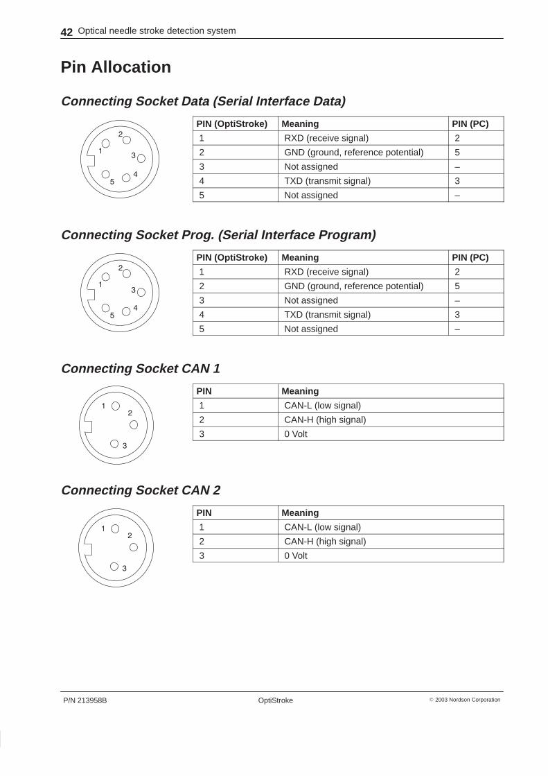
Pin Allocation
Connecting Socket Data (Serial Interface Data)
PIN (OptiStroke) Meaning PIN (PC)
1 RXD (receive signal) 2
2 GND (ground, reference potential) 5
3 Not assigned –
4 TXD (transmit signal) 3
5 Not assigned –
Connecting Socket Prog. (Serial Interface Program)
PIN (OptiStroke) Meaning PIN (PC)
1 RXD (receive signal) 2
2 GND (ground, reference potential) 5
3 Not assigned –
4 TXD (transmit signal) 3
5 Not assigned –
Connecting Socket CAN 1
PIN Meaning
1 CAN-L (low signal)
2 CAN-H (high signal)
3 0 Volt
Connecting Socket CAN 2
PIN Meaning
1 CAN-L (low signal)
2 CAN-H (high signal)
3 0 Volt

Optical needle stroke detection system 43
P/N 213958B� 2003 Nordson Corporation OptiStroke
Appendix
DIP Switch Settings
Master Unit
DIP switch Position Function Position Function
1 to 4 ON Determines the type ofcontrol module connected tothe channel. (Open, whenneedle is up: e.g. Universal).
OFF Determines the type ofcontrol module connected tothe channel. (Open, whenneedle is down: e.g. EP 10).
5 ON Master unit – –
6 ON 1 Slave unit connected OFF 2 Slave units connected
7 ON Master unit OFF Slave unit connected
8 ON Terminating resistor activated(for first and last unit)
OFF Terminating resistor notactivated (for second of threeunits)
Slave Unit
DIP switch Position Function Position Function
1 to 4 ON Determines the type ofcontrol module connected tothe channel. (Open, whenneedle is up: e.g. Universal).
OFF Determines the type ofcontrol module connected tothe channel. (Open, whenneedle is down: e.g. EP 10).
5 – – OFF Slave unit
6 ON Slave unit number 1 OFF Slave unit number 2
7 ON – OFF Slave unit
8 ON Terminating resistor activated(for first and last unit)
OFF Terminating resistor notactivated (for second of threeunits)

MASTER
1 2 3 4 5 6 7 8
ON
1 2 3 4 5 6 7 8
ON
1 2 3 4 5 6 7 8
ON
MASTER
SLAVE
1 2 3 4 5 6 7 8
ON
1 2 3 4 5 6 7 8
ON
MASTER
SLAVE 1
1 2 3 4 5 6 7 8
ON
SLAVE 2
44 Optical needle stroke detection system
P/N 213958B � 2003 Nordson CorporationOptiStroke
DIP Switch Settings (contd.)
The position of the first four DIP switches is not relevant to the master –slave configuration. They determine the type of control module connected.
OptiStroke consists of one master unit.
Fig. 34
OptiStroke consists of one master unit and one connected slave unit.
Fig. 35
OptiStroke consists of one master unit and two connected slave units.
Fig. 36

Optical needle stroke detection system 45
P/N 213958B� 2003 Nordson Corporation OptiStroke
Transmission Log
Factory Settings (Without Status Bytes)� The log is automatically transmitted once per second.
� Values for nonexistent channels are set to 0 (zero)
� Values for bad strokes are set to 0 (zero) and do not flow into calculationof the average for the channel.
NOTE: Setting of serial interface Data:Baud rate = 38400, 8 data bits, no parity, 1 stop bit
Byte no. Assignment
1 to 3 Start byte (X = 120 = 0x78)
4 Channel 1: On edge
(time, max. 100, value must be multiplied by 1 ms)
5 Channel 1: On edge
(decimal place, max. 99, value must be multiplied by 0.01 ms)
6 Channel 1: Off edge (time in ms, maximum 100 ms)
(time, max. 100, value must be multiplied by 1 ms)
7 Channel 1: Off edge (time in �s, maximum 99 �s)
(decimal place, max. 99, value must be multiplied by 0.01 ms)
8 Transmitted light in % (1 to 100)
9 to 63 Channels 2 to 12 (transmission as with byte 4 to 8)
64 Check sum (x-or link from byte 4 to 63)
65 Stop byte (Z = 122 = 0x7A)

46 Optical needle stroke detection system
P/N 213958B � 2003 Nordson CorporationOptiStroke
Transmission Log (contd.)
Settings (With Status Bytes)
NOTE: The status bytes can be used for system analysis
NOTE: Setting of serial interface Data:Baud rate = 38400, 8 data bits, no parity, 1 stop bit
Byte no. Assignment
1 to 3 Start byte (X = 120 = 0x78)
4 Channel 1: On edge
(time, max. 100, value must be multiplied by 1 ms)
5 Channel 1: On edge
(decimal place, max. 99, multiply value by 0.01 ms)
6 Channel 1: Off edge (time in ms, maximum 100 ms)
(time, max. 100, value must be multiplied by 1 ms)
7 Channel 1: Off edge (time in �s, maximum 99 �s)
(decimal place, max. 99, multiply value by 0.01 ms)
8 Transmitted light in % (1 to 100)
9 Status word # 1 (high byte)
10 Status word # 1 (low byte)
11 Status word # 2 (high byte)
12 Status word # 2 (low byte)
13 to 111 Channels 2 to 12 (transmission as with byte 4 to 12)
112 Check sum (x-or link from byte 4 to 111)
113 Stop byte (Z = 122 = 0x7A)

Optical needle stroke detection system 47
P/N 213958B� 2003 Nordson Corporation OptiStroke
Status BytesNOTE: The Simplified Phase Model shows additional information on thephases.
Status Word # 1 – Bit 0 to 7NOTE: The status bits 0 to 8 will only be reset by a loss of voltage supply.
Bit no. Bit name Function Description
0 Status bit 1 Life-time toggle 3 s Changes every 3 seconds, if measurementprocessor okay
1 Status bit 2 Set upon return fromphase 1 –> phase 0
Optical fiber cable connected properly? Distancebetween optical fiber cable and reflection surfacetoo large?
Can only be reset by switching off supply voltage.
2 Status bit 3 Set upon return fromphase 1 –> phase 0
Optical fiber cable connected properly? Distancebetween optical fiber cable and reflection surfacetoo small?
Can only be reset by switching off supply voltage.
3 Status bit 4 Set upon return fromphase 2 –> phase 0
Stroke signal level too large
Can only be reset by switching off supply voltage.
4 Status bit 5 Set upon return fromphase 2 –> phase 0
No needle stroke or distance between opticalfiber cable and reflection surface too large
Can only be reset by switching off supply voltage.
5 Status bit 6 Set upon return fromphase 2 –> phase 0
Distance between optical fiber cable andreflection surface too small
6 Status bit 7 Set upon return fromphase 3 –> phase 0
Stroke signal level too large
Can only be reset by switching off supply voltage.
7 Not used – – – –
48 Optical needle stroke detection system
P/N 213958B � 2003 Nordson CorporationOptiStroke
Status Bytes (contd.)
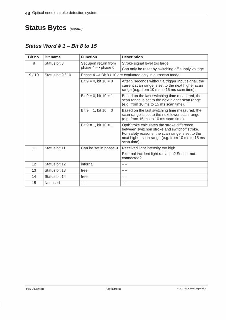
Status Word # 1 – Bit 8 to 15
Bit no. Bit name Function Description
8 Status bit 8 Set upon return fromphase 4 –> phase 0
Stroke signal level too large
Can only be reset by switching off supply voltage.
9 / 10 Status bit 9 / 10 Phase 4 –> Bit 9 / 10 are evaluated only in autoscan mode
Bit 9 = 0, bit 10 = 0 After 5 seconds without a trigger input signal, thecurrent scan range is set to the next higher scanrange (e.g. from 10 ms to 15 ms scan time).
Bit 9 = 0, bit 10 = 1 Based on the last switching time measured, thescan range is set to the next higher scan range(e.g. from 10 ms to 15 ms scan time).
Bit 9 = 1, bit 10 = 0 Based on the last switching time measured, thescan range is set to the next lower scan range(e.g. from 15 ms to 10 ms scan time).
Bit 9 = 1, bit 10 = 1 OptiStroke calculates the stroke differencebetween switchon stroke and switchoff stroke.For safety reasons, the scan range is set to thenext higher scan range (e.g. from 10 ms to 15 msscan time).
11 Status bit 11 Can be set in phase 0 Received light intensity too high.
External incident light radiation? Sensor notconnected?
12 Status bit 12 internal – –
13 Status bit 13 free – –
14 Status bit 14 free – –
15 Not used – – – –

Optical needle stroke detection system 49
P/N 213958B� 2003 Nordson Corporation OptiStroke
Status Word # 2 – Bit 0 to 7
Bit no. Bit name Function Description
0 Status bit 15 Set when measuringchannel is in phase 0
Assume calibration parameters from previousruns of phase 4 or determine start parameters.
1 Status bit 16 Set when measuringchannel is in phase 1
Measurement amplifier is calibrated
2 Status bit 17 Set when measuringchannel is in phase 2
Control stabilization phase, function test
3 Status bit 18 Set when measuringchannel is in phase 3
Channel ready, measured values are sent andalarm functions are active.
4 Status bit 19 Set when measuringchannel is in phase 4
Channel is fully stabilized, measured values aresent and alarm functions are active. Calibrationparameters are saved.
5 Status bit 20 Free – –
6 Status bit 21 Free – –
7 Not used – – – –

50 Optical needle stroke detection system
P/N 213958B � 2003 Nordson CorporationOptiStroke
Status Bytes (contd.)
Status Word # 2 – Bit 8 to 15
Bit no. Bit name Function Description
8 Status bit 22 Set, if PC analysis isactive
During activated PC channel analysis, thischannel may work below capacity
9 Status bit 23 Set, if ”Offset<>0” The real switching time of this channel is addedto a � offset value (PC software), and the sum istransmitted via the data interface
10 Status bit 24 Set at LEDtransmission = 100%
Incorrect sensor position or sensor possibly dirty
11 Status bit 25 Set at offset amplifica-tion factor = 100%
Incorrect sensor position or no needle stroke
12 Status bit 26 Set when data tocontrol unit =0.00/0.00
During control stabilization or when no needlestroke
13 Status bit 27 Set at stroke signallevel < 12%
When completely stabilized, the stroke signallevel is approx. 25 % of the input voltage range.Thus with this status bit a needle stroke of < 50%is evaluated.
14 Status bit 28 Set, when nomeasurement CPU inCAN bus system
The CAN bus line may be defective or notconnected
15 Not used – – – –

Optical needle stroke detection system 51
P/N 213958B� 2003 Nordson Corporation OptiStroke
Evaluation of Status Bytes – Example 1Status bytes for channel 1: 00.10x12.00
00 is the value of status word #2, bit 8 to 15
10 is the value of status word #2, bit 0 to 7
12 is the value of status word #1, bit 8 to 15
00 is the value of status word #1, bit 0 to 7
Hex code Binary code Status word / bit no. Meaning
00 0 #2 / 8 During activated PC channel analysis, thischannel may work below capacity
10 10000 #2 / 4 Stabilized channel control, measured values aresent and alarm functions are working
12 10010 #1 / 9 = 1 and
#1 / 10 = 0
Based on the last switching time measured, thescan range is set to the next lower scan range(e.g. from 15 ms to 10 ms scan time).
#1 / 12 – –
00 0 #1 / 0 Status bit changes every 3 seconds, ifmeasurement processor okay
NOTE: The evaluation of the status bytes indicates that the measurementson channel 1 were performed correctly.

52 Optical needle stroke detection system
P/N 213958B � 2003 Nordson CorporationOptiStroke
Status Bytes (contd.)
Evaluation of Status Bytes – Example 2
Status bytes for channel 4: 30.02x10.02
30 is the value of status word #2, bit 8 to 15
02 is the value of status word #2, bit 0 to 7
10 is the value of status word #1, bit 8 to 15
02 is the value of status word #1, bit 0 to 7
Hex code Binary code Status word / bit no. Meaning
30 110000 #2 / 12 During control stabilization or when no needlestroke (data to control unit: 0.00 / 0.00)
#2 / 13 When completely stabilized, the stroke signallevel should be approx. 25% (needle stroke < 12 %)
02 10 #2 / 1 Measurement amplifier is calibrated
10 10000 #1 / 12 – –
02 10 #1 / 1 Sensor connected properly? Sensor distance toogreat?
NOTE: The evaluation of the status bytes indicates that channel 4 is not yetready for measurement. There may be a sensor error.

Optical needle stroke detection system 53
P/N 213958B� 2003 Nordson Corporation OptiStroke
Simplified Phase Model
no
no
yes
yes
1
Fig. 37

54 Optical needle stroke detection system
P/N 213958B � 2003 Nordson CorporationOptiStroke
OptiStroke Board
2 310
9
8
7
6
1
5
4
4
4
4
D21
D26
D18
D25
D24
D23
D22
D27 D28 D29 D30
Fig. 38 Overview of the essential components
1 Indicator beacon LEDs (D18, D21, D26)
2 8-pin DIP switch3 Transmitted Light LEDs4 Optical fiber cable input sockets
(K1 to K4)
5 Trigger LEDs6 HAN 24 socket7 Data interface (Data)8 PC interface (Prog)
9 CAN 1 BUS10 CAN 2 BUS

Optical needle stroke detection system 55
P/N 213958B� 2003 Nordson Corporation OptiStroke
Extended Missing Needle Stroke DetectionNOTE: The following explanations refer to the section Description, Setup –Missing Needle Stroke Detection.
Example 1: Normal ModeThe mechanical needle stroke falls below 20 %. This means that the controlmodule opens only slightly.
The signal strength falls below the threshold missing needle stroke of 5 %. Itis then interpreted as a missing needle stroke, and an alarm is issued.
If this error continues to exist, OptiStroke slowly regulates the signalstrength back to 25 %. The error is no longer displayed. The switching timesare still measured and evaluated.
If the control module fails completely, an error indication is issued. Completefailure can not be compensated.
Example 2: Operation with Extended Missing Needle Stroke DetectionTo eliminate the possibility of the signal strength being regulated whenstroke changes are of longer duration, the function extended missing needlestroke detection can be used.
Advantage: The 20 % error mentioned in example 1 is shown continuouslywithout this function and can not be regulated.
Disadvantage: If this function is used, OptiStroke must definitely beoperated properly.
Every time the measurement environment is changed (startup, replacementof control modules and optical fiber cables, maintenance, other servicework), all relevant settings under setup must be changed and activated.
1. Verify that all channels that should be activated for the function havebeen preselected.
2. Activate the function recalibration, actual needle strokes equals max.needle strokes.
3. Acknowledge changes with OK.
Fig. 39

56 Optical needle stroke detection system
P/N 213958B � 2003 Nordson CorporationOptiStroke