Optical Fiber Cable Environmental Qualification
24
Optical Fiber Cable Environmental Qualification © 2013 CableLAN Products 1-800-840-6655 Jan Pirrong CableLAN Products, Inc. EQ Technical Forum Shanghai, China October 14, 2014
Transcript of Optical Fiber Cable Environmental Qualification
Optical Fiber Cable Environmental Qualification
© 2013 CableLAN Products 1-800-840-6655
Jan Pirrong CableLAN Products, Inc.
EQ Technical Forum Shanghai, China
October 14, 2014
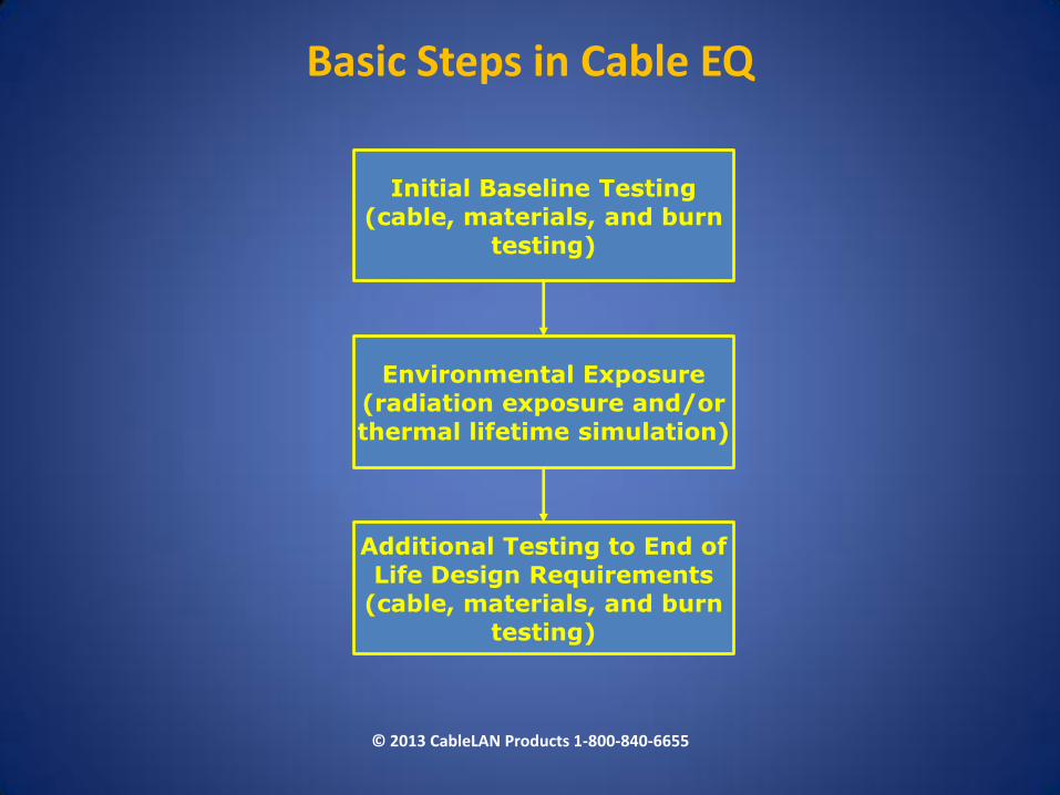
Basic Steps in Cable EQ
Initial Baseline Testing
(cable, materials, and burn
testing)
Environmental Exposure
(radiation exposure and/or
thermal lifetime simulation)
Additional Testing to End of
Life Design Requirements
(cable, materials, and burn
testing)
© 2013 CableLAN Products 1-800-840-6655
Optical Fiber in Radiation Environments
• Standard optical fibers may be highly sensitive to radiation even at low doses
• Radiation effects on fiber performance must be carefully characterized before deployment into high radiation environments
• Different fibers may be required for different applications
© 2013 CableLAN Products 1-800-840-6655
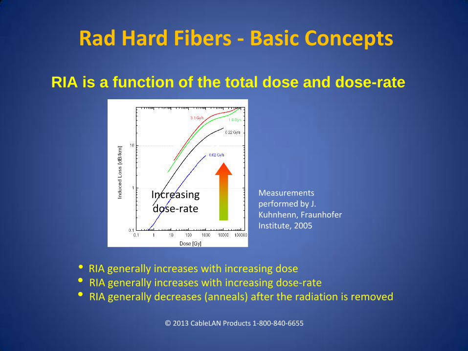
RIA is a function of the total dose and dose-rate
• RIA generally increases with increasing dose • RIA generally increases with increasing dose-rate • RIA generally decreases (anneals) after the radiation is removed
Measurements performed by J. Kuhnhenn, Fraunhofer Institute, 2005
Increasing dose-rate
© 2013 CableLAN Products 1-800-840-6655
Rad Hard Fibers - Basic Concepts
© 2013 CableLAN Products 1-800-840-6655
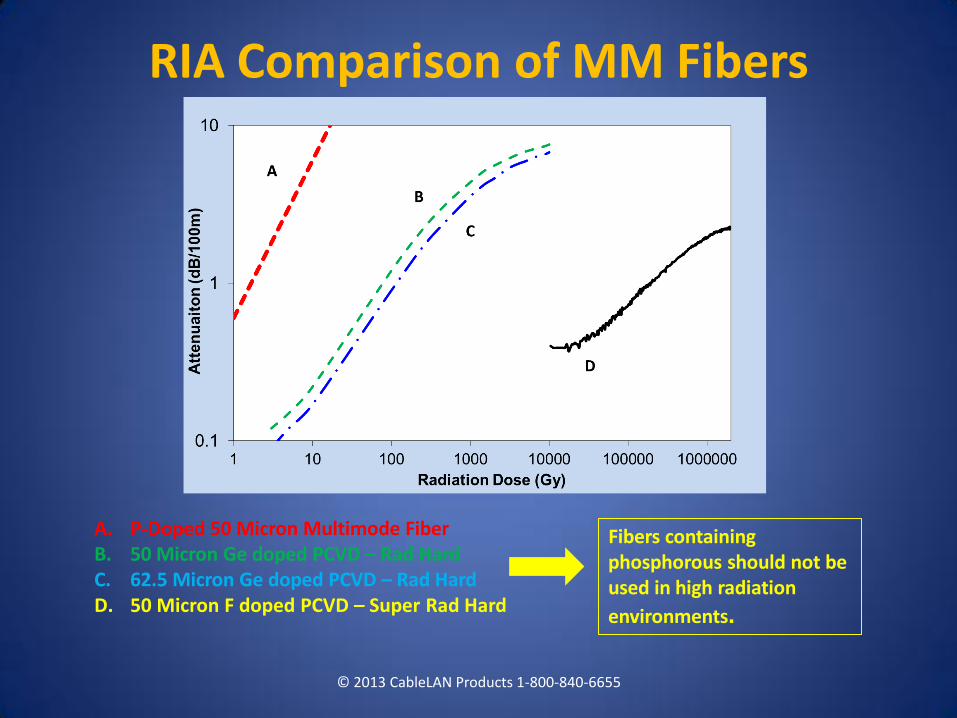
A. P-Doped 50 Micron Multimode Fiber B. 50 Micron Ge doped PCVD – Rad Hard C. 62.5 Micron Ge doped PCVD – Rad Hard D. 50 Micron F doped PCVD – Super Rad Hard
Fibers containing phosphorous should not be used in high radiation
environments.
RIA Comparison of MM Fibers
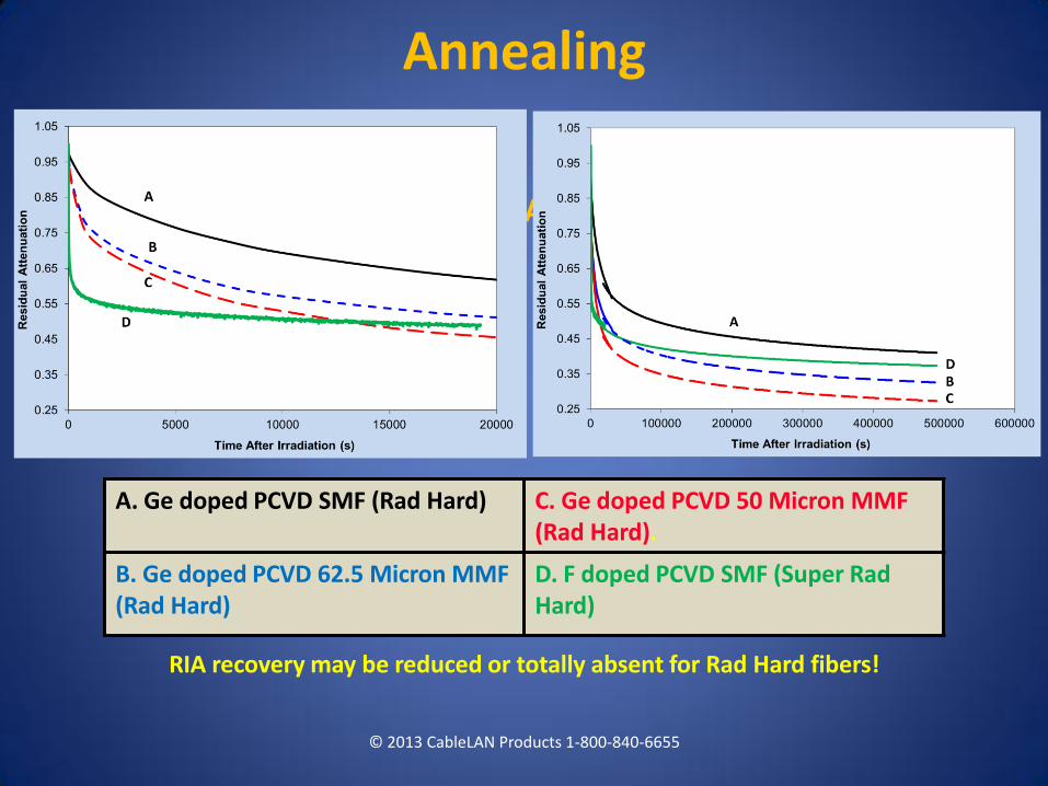
Results: RIA (Annealing)
RIA recovery may be reduced or totally absent for Rad Hard fibers!
© 2013 CableLAN Products 1-800-840-6655
Annealing
A. Ge doped PCVD SMF (Rad Hard) C. Ge doped PCVD 50 Micron MMF (Rad Hard).
B. Ge doped PCVD 62.5 Micron MMF (Rad Hard)
D. F doped PCVD SMF (Super Rad Hard)
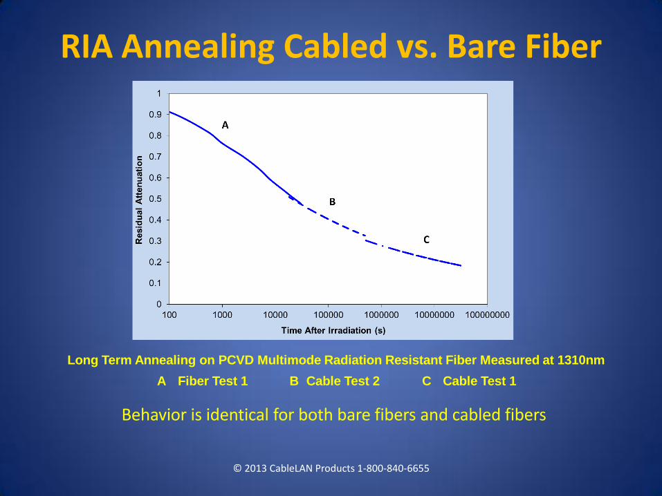
Long Term Annealing on PCVD Multimode Radiation Resistant Fiber Measured at 1310nm
A Fiber Test 1 B Cable Test 2 C Cable Test 1
Behavior is identical for both bare fibers and cabled fibers
© 2013 CableLAN Products 1-800-840-6655
RIA Annealing Cabled vs. Bare Fiber
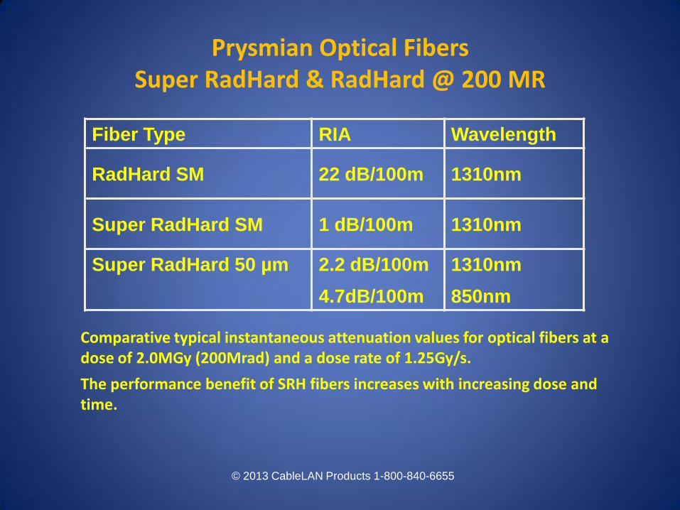
Comparative typical instantaneous attenuation values for optical fibers at a dose of 2.0MGy (200Mrad) and a dose rate of 1.25Gy/s.
The performance benefit of SRH fibers increases with increasing dose and time.
Fiber Type RIA Wavelength
RadHard SM 22 dB/100m 1310nm
Super RadHard SM 1 dB/100m 1310nm
Super RadHard 50 µm
2.2 dB/100m
4.7dB/100m
1310nm
850nm
© 2013 CableLAN Products 1-800-840-6655
Prysmian Optical Fibers Super RadHard & RadHard @ 200 MR
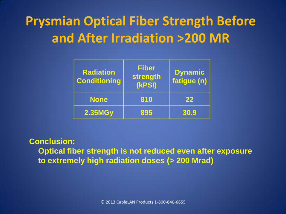
Conclusion:
Optical fiber strength is not reduced even after exposure
to extremely high radiation doses (> 200 Mrad)
Radiation
Conditioning
Fiber
strength
(kPSI)
Dynamic
fatigue (n)
None 810 22
2.35MGy 895 30.9
© 2013 CableLAN Products 1-800-840-6655
Prysmian Optical Fiber Strength Before and After Irradiation >200 MR
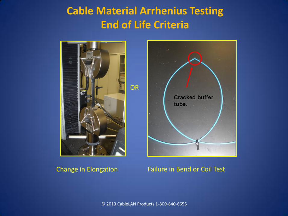
Cable Material Arrhenius Testing End of Life Criteria
© 2013 CableLAN Products 1-800-840-6655
Change in Elongation Failure in Bend or Coil Test
OR
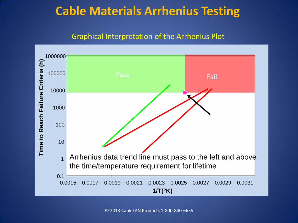
Cable Materials Arrhenius Testing
© 2013 CableLAN Products 1-800-840-6655
Graphical Interpretation of the Arrhenius Plot
0.1
1
10
100
1000
10000
100000
1000000
0.0015 0.0017 0.0019 0.0021 0.0023 0.0025 0.0027 0.0029 0.0031
1/T(°K)
Tim
e t
o R
ea
ch
Fa
ilu
re C
rite
ria
(h
)
Lifetime
Requirement (Time,
Temperature)
Pass Fail
Arrhenius
data trend
lines
Arrhenius data trend line must pass to the left and above
the time/temperature requirement for lifetime.
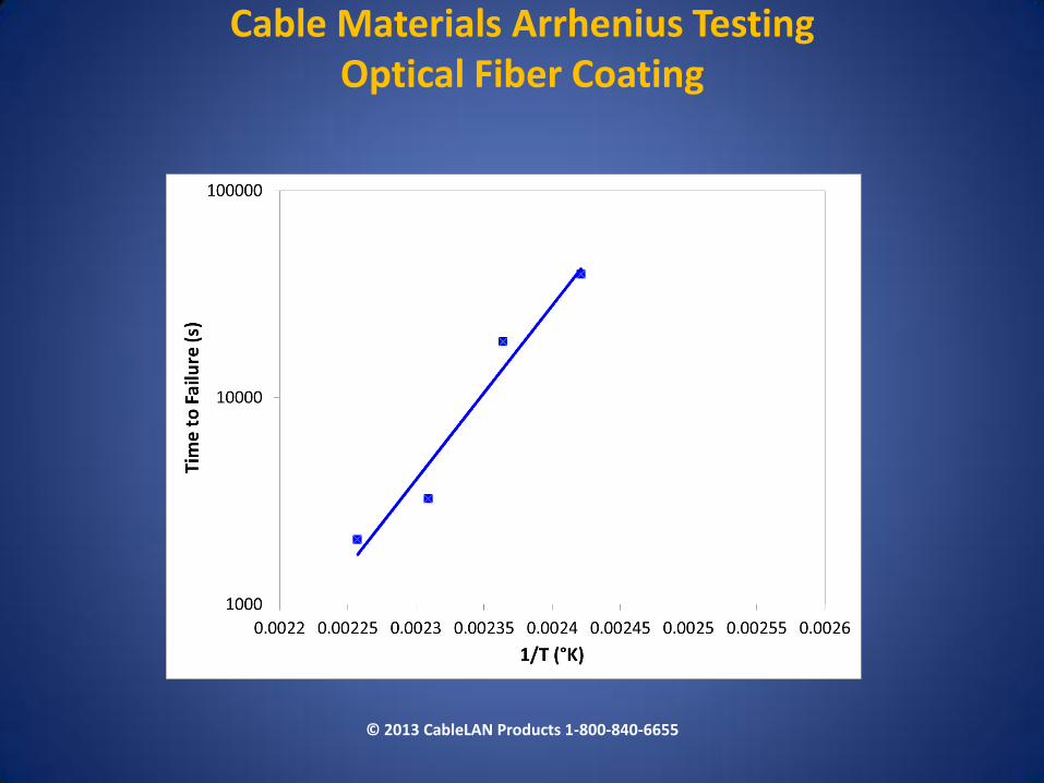
Cable Materials Arrhenius Testing Optical Fiber Coating
© 2013 CableLAN Products 1-800-840-6655
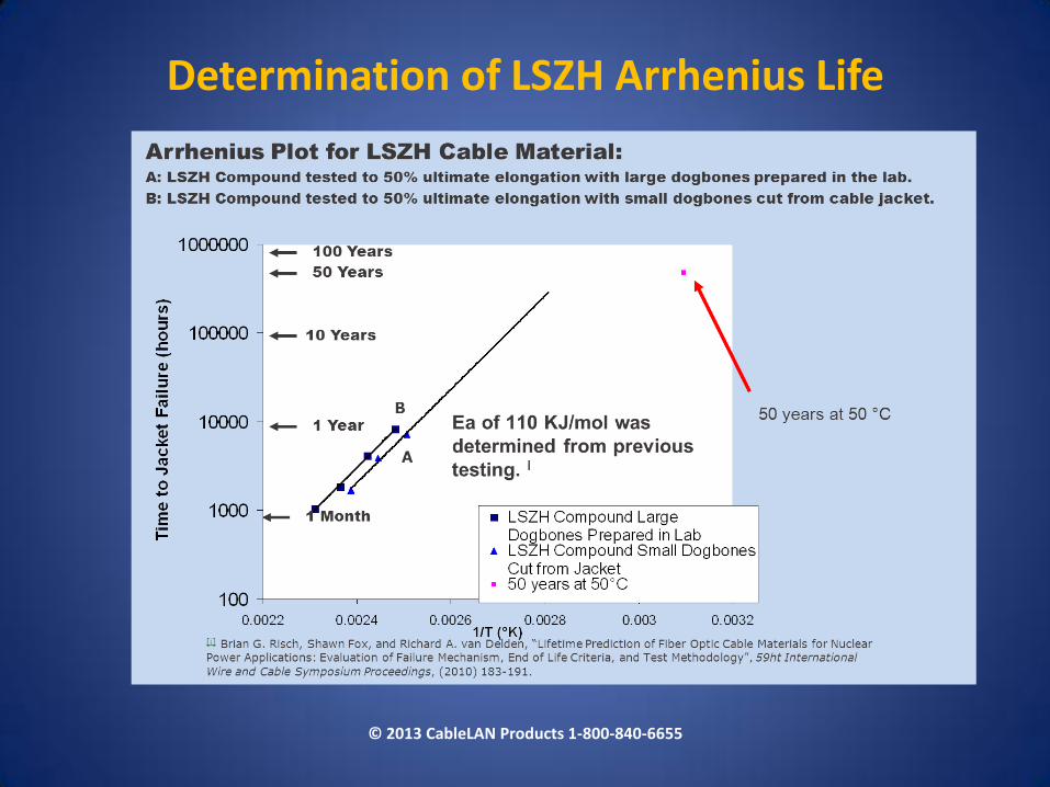
Determination of LSZH Arrhenius Life
© 2013 CableLAN Products 1-800-840-6655
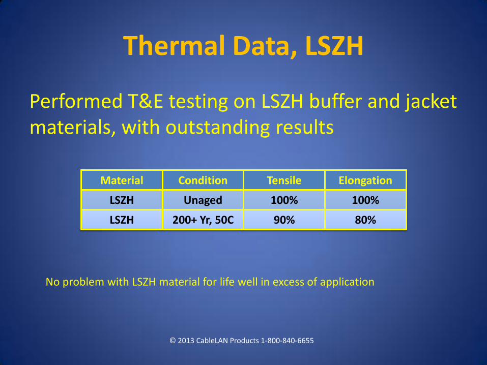
Thermal Data, LSZH
Performed T&E testing on LSZH buffer and jacket materials, with outstanding results
© 2013 CableLAN Products 1-800-840-6655
Material Condition Tensile Elongation
LSZH Unaged 100% 100%
LSZH 200+ Yr, 50C 90% 80%
No problem with LSZH material for life well in excess of application
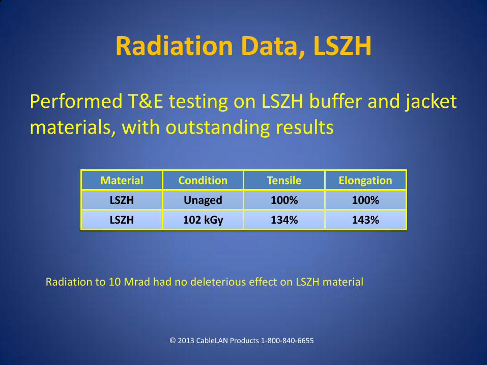
Radiation Data, LSZH
Performed T&E testing on LSZH buffer and jacket materials, with outstanding results
© 2013 CableLAN Products 1-800-840-6655
Material Condition Tensile Elongation
LSZH Unaged 100% 100%
LSZH 102 kGy 134% 143%
Radiation to 10 Mrad had no deleterious effect on LSZH material
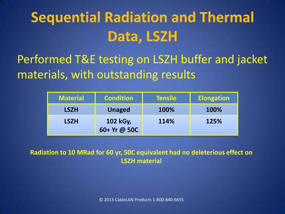
Sequential Radiation and Thermal Data, LSZH
Performed T&E testing on LSZH buffer and jacket materials, with outstanding results
© 2013 CableLAN Products 1-800-840-6655
Material Condition Tensile Elongation
LSZH Unaged 100% 100%
LSZH 102 kGy, 60+ Yr @ 50C
114% 125%
Radiation to 10 MRad for 60 yr, 50C equivalent had no deleterious effect on LSZH material
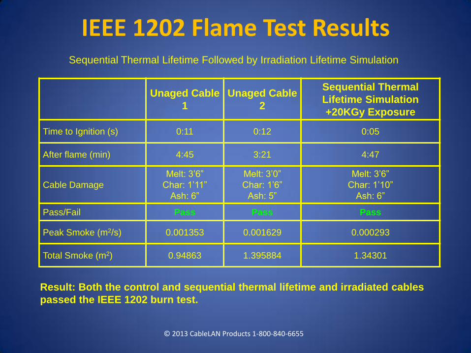
Sequential Thermal Lifetime Followed by Irradiation Lifetime Simulation
Result: Both the control and sequential thermal lifetime and irradiated cables
passed the IEEE 1202 burn test.
Unaged Cable
1
Unaged Cable
2
Sequential Thermal
Lifetime Simulation
+20KGy Exposure
Time to Ignition (s) 0:11 0:12 0:05
After flame (min) 4:45 3:21 4:47
Cable Damage
Melt: 3’6”
Char: 1’11”
Ash: 6”
Melt: 3’0”
Char: 1’6”
Ash: 5”
Melt: 3’6”
Char: 1’10”
Ash: 6”
Pass/Fail Pass Pass Pass
Peak Smoke (m2/s) 0.001353 0.001629 0.000293
Total Smoke (m2) 0.94863 1.395884 1.34301
© 2013 CableLAN Products 1-800-840-6655
IEEE 1202 Flame Test Results
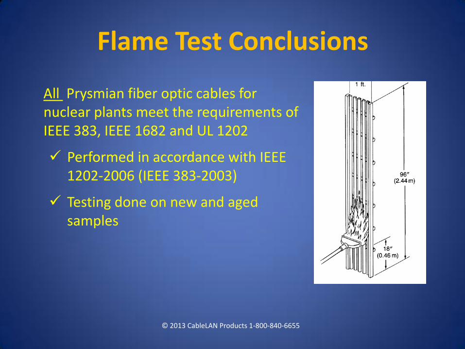
All Prysmian fiber optic cables for nuclear plants meet the requirements of IEEE 383, IEEE 1682 and UL 1202
Performed in accordance with IEEE 1202-2006 (IEEE 383-2003)
Testing done on new and aged samples
© 2013 CableLAN Products 1-800-840-6655
Flame Test Conclusions
Seismic
© 2013 CableLAN Products 1-800-840-6655
Seismically tested fiber optic cable assemblies, both duplex and simplex, at Trentec, Cincinnati, OH (2009)
Tested items included: Draka S690T breakout cable, Radiant ST connectors, and Fibraconn patch panels.
Subjected to 6 seismic events (5 x OBE 1 X SSE), monitoring attenuation via a power meter throughout each event.
Result: Assemblies passed, with very limited (<0.1 db, most <0.05 db) variation in received power.
Prysmian Cable EQ Summary
Prysmian nuclear cables have been successfully tested for:
Optical Fibers: Exposure up to 200 Mrad
Fiber Coating: Thermal and radiation
LSZH Materials: 60 yr@ 50C, 10 Mrad (sequential)
Cables: Flame testing IEEE 1202, 383, 1682 flame test, unaged and sequentially aged
Seismic
© 2013 CableLAN Products 1-800-840-6655
Fiber Optic Cable Condition Monitoring
Fibers characteristics can be directly measured by having access to one or both ends of a cable run Two methods
1. Periodic measurement 2. Continuous (real time) measurement
© 2013 CableLAN Products 1-800-840-6655
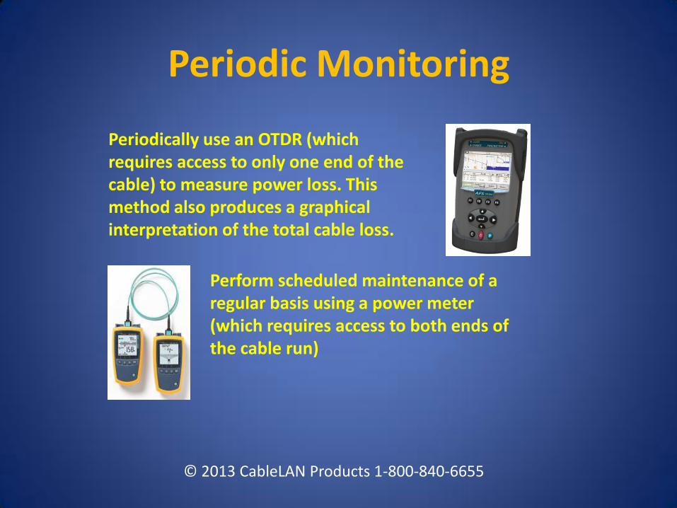
Periodic Monitoring
Perform scheduled maintenance of a regular basis using a power meter (which requires access to both ends of the cable run)
Periodically use an OTDR (which requires access to only one end of the cable) to measure power loss. This method also produces a graphical interpretation of the total cable loss.
© 2013 CableLAN Products 1-800-840-6655
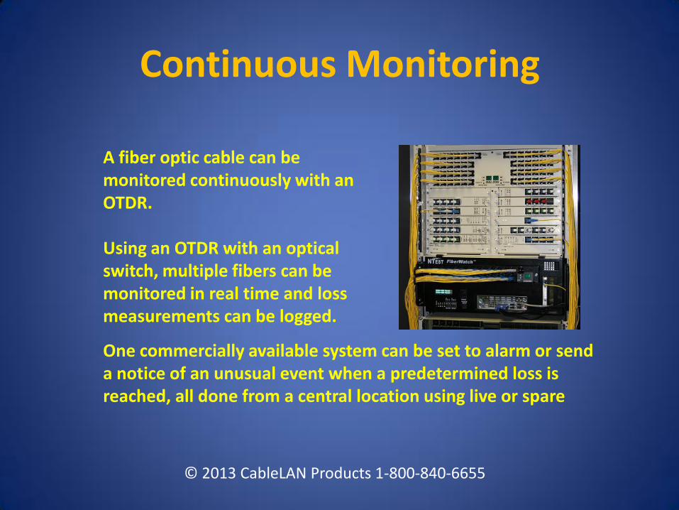
Continuous Monitoring
A fiber optic cable can be monitored continuously with an OTDR. Using an OTDR with an optical switch, multiple fibers can be monitored in real time and loss measurements can be logged. One commercially available system can be set to alarm or send a notice of an unusual event when a predetermined loss is reached, all done from a central location using live or spare
© 2013 CableLAN Products 1-800-840-6655
Thank You!
Questions?
© 2013 CableLAN Products 1-800-840-6655