OPTICAL CODE-DIVISION MULTIPLE ACCESS … · Abstract Optical Code-Division Multiple Access...
76
OPTICAL CODE-DIVISION MULTIPLE ACCESS NETWORKS: QUANTIFYING AND ACHIEVING TKE ULTIMATE PERFORMANCE Tung-Wah Frederick Chang A thesis submitted in conformity with the requirements for the degree of Master of Applied Science Graduate Department of Electrical and Computer Engineering University of Toronto Copyright @ 2000 by Tung-Wah F'rederick Chang
Transcript of OPTICAL CODE-DIVISION MULTIPLE ACCESS … · Abstract Optical Code-Division Multiple Access...
OPTICAL CODE-DIVISION MULTIPLE ACCESS NETWORKS: QUANTIFYING AND ACHIEVING TKE ULTIMATE PERFORMANCE
Tung-Wah Frederick Chang
A thesis submitted in conformity with the requirements for the degree of Master of Applied Science
Graduate Department of Electrical and Computer Engineering University of Toronto
Copyright @ 2000 by Tung-Wah F'rederick Chang
National Library I * m of Canada Bibliothèque nationale du Canada
Acquisitions and Acquisitions et Bibliographie Services services bibliographiques
395 Wellington Street 395. rue Wellington Ottawa ON K1A O N 4 Ottawa ON K I A ON4 Canada Canada
The author has granted a non- exclusive licence allowing the National Library of Canada to reproduce, loan, distribute or sell copies of this thesis in microfonn, paper or electronic formats.
The author retauis ownership of the copyright in this thesis. Neither the thesis nor substantial extracts fkom it may be printed or otherwise reproduced without the author's pennission.
L'auteur a accordé une licence non exclusive permettant a la Bibliothèque nationale du Canada de reproduire, prêter, disîribuer ou vendre des copies de cette thèse sous la forme de microfiche/f3m, de reproduction sur papier ou sur format électronique.
L'auteur conserve la propneté du droit d'auteur qui protège cette thèse. Ni la thèse ni des extraits substantiels de celle-ci ne doivent être imprimes ou autrement reproduits sans son autorisation.
Abstract
Optical Code-Division Multiple Access Networks: Quantifying and Achieving the
Ultimate Performance
Tung-Wah Frederick Chang
Master of Applied Science
Graduate Department of Electrical and Computer Engineering
University of Toronto
2000
This work reveals for the first time the ultimate spectral efficiency of incoherent
optical code-division multiple access (O-CDMA) systems. It shows for the first time how
to approach this ultimate limit practically.
A decision rule for O-CDMA systems using unipolar codes is derived and is proven
optimal. A fully general scheme is developed to transmit any bipolar code over the
optical unipolar channel while maint aining the performance advantage of bipolar codes.
The spectral efficiency of the proposed EOE system is shown to approach the upper Iimit
of an optimum bipolar baseband system using a single-user detector.
Optical and hybrid optical-electronic implementations of these novel systems are ex-
plored and compared.
This work lays a foundation for future generations of local area networks which will
provide high bandwidth and flexibility.
Acknowledgement s
1 would like to express my sincere gratitude and appreciation to my s u p e ~ s o r , Ted
Sargent, for his inspiration, guidance and encouragement.
1 am grateful to the members of Sargent's group for their indispensable technical
support and valuable friendship.
1 also thaxik everyone in Wycliffe College for making the residence a warm place to
stay away from home.
My parents have been the ultimate source of support not only during my studies but
also throughout my life. 1 can never thank them enough for their continuous encourage-
ment, ever-lasting love and care.
Finally, 1 acknowledge NSERC for the financial support during this work.
Contents
1 Introduction 1
. . . . . . . . . . . . . . . . . . . . . . . . . . . . . . . . . . . 1.1 Motivation 1
1.2 Literature Review . . . . . . . . . . . . . . . . . . . . . . . . . . . . . . . 2
. . . . . . . . . . . . . . . . . . . . . . . 1.2.1 Multiple Access Schemes 2
1.2.2 O-CDMA Systems with Unipolar Codes . . . . . . . . . . . . . . 3
. . . . . . . . . . . . . 1.2.3 O-CDMA Systems with Bipolar Codes .. 6
. . . . . . . . . . . . . . . . . . . . . . . . . . . . . . . . . . 1.3 Opportunity 7
. . . . . . . . . . . . . . . . . . . . . . . . . . . . . . . . 1.4 Thesis Structure 8
2 Analytic Framework 9
. . . . . . . . . . . . . . . . . . . . . . . . . . . . . . . . . . 2.1 Introduction 9
. . . . . . . . . . . . . . . . . . . 2.2 System -4rchitecture and .A ssumptions 9
. . . . . . . . . . . . . . . . . . . . . . . . . . . . . . . . 2.3 Simulation Tool 12
. . . . . . . . . . . . . . . . . . . . . . . . . . . . . . . . . . . 2.4 Summary 13
3 On-Off Keying with MAP Detection 14
. . . . . . . . . . . . . . . . . . . . . . . . . . . . . . . . . . 3.1 Introduction 14
. . . . . . . . . . . . . . . . . . . . . . . . . 3.2 Signal Space Representation 15
. . . . . . . . . . . . . . . . . . . . . . . . . . . 3.3 The MAP Decision Rule 16
. . . . . . . . . . . . . . . . . . . . . . . . . . . 3.4 Decision Rule Derivation 17
. . . . . . . . . . . . . . . . . . . . . . . . . . . . . 3.5 Performance Analysis 21
. . . . . . . . . . . . . . . . . . . . . . . . . . . . . . . . . . 3.6 Conclusions 26
4 Bipolar Signaling over the Unipolar Channel 28
. . . . . . . . . . . . . . . . . . . . . . . . . . . . . . . . . . 4 Introduction 28
. . . . . . . . . . . . . . . 4.2 A BPSK CDMA System Using Bipolar Codes 29
. . . . . . . . . . . . . . . . . . . . . . . 4.3 Baseband BPSK CDMA System 31
. . . . . . . . . . . . . . . . . . . . 4.4 Bipolar Codes over Unipolar Channel 32
. . . . . . . . . . . . . . . . . . . . . . . . . . . 4.5 Performance Comparison 34
. . . . . . . . . . . . . . . . . . . . . . . . . . . . . . . . . . 4.6 Conclusions 36
5 Discussion and Generalization 38
. . . . . . . . . . . . . . . . . . . . . . . . . . . . . . . . . . 5-1 Introduction 38
. . . . . . . . . . . . . . . . . 5.2 BER Performance and Spectral Efficiency 39
. . . . . . . . . . . . . . . . . . . . . . . . . . 5-3 Hardwarehplementation 43
. . . . . . . . . . . . . . . . . . . . . . . . . . . . . . . 5.3.1 Structure 44
. . . . . . . . . . . . . . . . . . . . . . . . . . . . . . . 5.3.2 FIexibiLity 46
. . . . . . . . . . . . . . . . . . 5.3.3 Hardware Speed and Complexity 47
. . . . . . . . . . . . . . . . . . . . . . 5.3.4 Wavelength expandability 48
. . . . . . . . . . . . . . . . . . . . . . . . . 5.3.5 A practical example 51
. . . . . . . . . . . . . . . . . . . . . . . . . . . . . . . 5.4 System Selection 52
. . . . . . . . . . . . . . . . . . . . . . . . . . . . . . . . . . 5.5 Conclusions 03
6 Conclusions 54
. . . . . . . . . . . . . . . . . . . . . . . . . . . . . . 6.1 Summary of Work 54
. . . . . . . . . . . . . . . . . . . . . . . . 6.2 Future Work and Opportunity 55
. . . . . . . . . . . . . . . . . . . . . . . 6.2.1 Effects of Physical Noise 56
. . . . . . . . . . . . . . . 6.2.2 Interfacing with Higher Network Layers 56
. . . . . . . . . . . . . . . . . . 6.2.3 Development of Photonic Devices 57
. . . . . . . . . . . . . . . . . . . . . . . . . . . . . 6.3 Significance of Work 58
B ib liograp hy
List of Tables
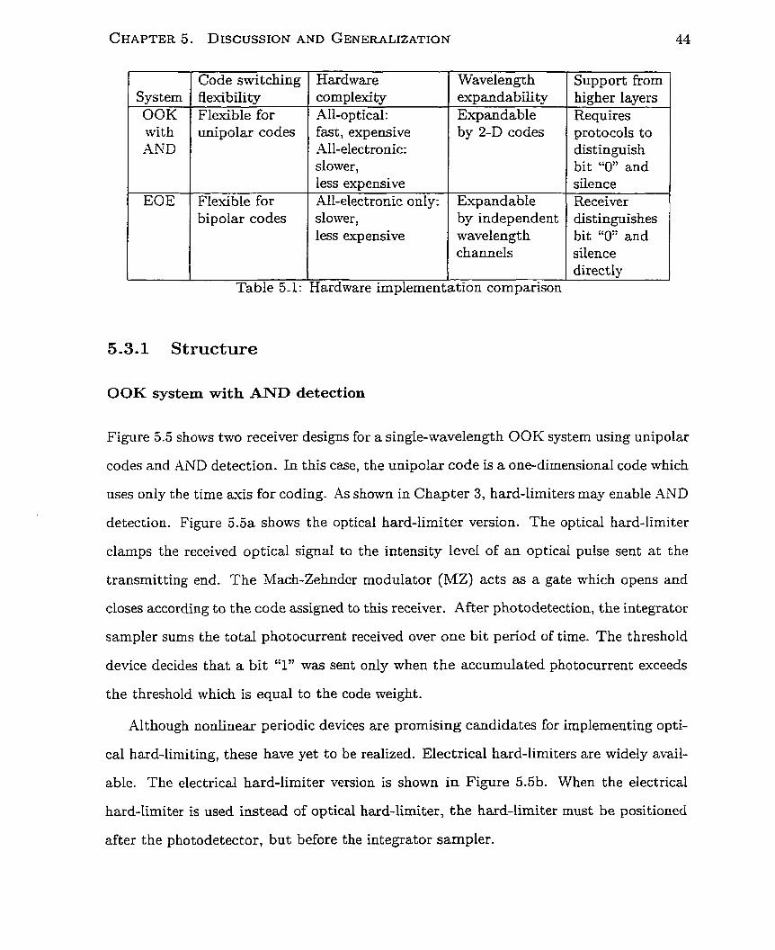
5.1 Hardware implementation cornparison . . . . . . . . . . . . . . . . . . . . 44
vii
List of Figures
1.1 An optical CDMA network using two-dimensional codes (Taken from [l]).
1.2 Ternporal/spatial single-pulse-per-row (T/S SPR) code. (Taken from [-21).
1.3 Multiple-pulse-per-row (MPR) code. (Reproduced from [3]). . . . . . . .
1.4 An optical CDMA system using Gold sequence. (Reproduced from [4]). .
1.5 Conversion of bipolar codes to unipolar codes and SIK. (a) Bipolar Gold
sequence to unipolar Gold sequence. (b) Bit "1" and bit "0" representation
inSIK . . . . . . . . . . . . . . . . . . . . . . . . . . . . . . . . . . . . . .
2.1 The optical LAN using star topology . . . . . . . . . . . . - . . . . . . .
2.2 ,4n MW-O-CDMA code . . . . . - . . . . . . . . . . . . . . . . . . . . .
3.1 The received signal . . . . . . . . . . . . . . . . . . . . . . . . . . . . . .
3.2 The symbol for a) bit "1" and b) bit ''0" . . . . . . . . . . . . . . . . .
3.3 BER performance against the number of active users (N,,) for randorn
codes. Lines represent calculation results fron (3.19) and (3.17). The
symbols represents Monte Car10 simulation results. For al1 cases, Nw =
5 , L t = 2 5 , W = 5 . . . . . . . . . . . . . . . . . . . . , . . . . . . . . . . .
3.4 BER performance as a function of the number of active users (Nsu) for
random codes. Results are obtained using (3.19) and (3.17) for W =
36, D = 1333. . . . . . . . . . . . . . . . . . . . . . . . . . . . . . . . . .
3.5 Spectral efficiency Improvement Factor vs. BER. . . . . . . . . . . . . .
BER performance against the nurnber of active users (N,) for random
codes and deterministic codes. Lines represent calculation results from
(3.19) and (3.17). The symbols represents Monte Carlo simulation results.
For al1 cases, Nv = 5 , Lt = 25, W = 5. - . . . . . . . . . . . . . . . . . .
A conventional bipolar CDMA system with coherent detection . . . . . .
. . . . . . . . . . . . . . . . . . . . . A baseband bipolar CDMA system
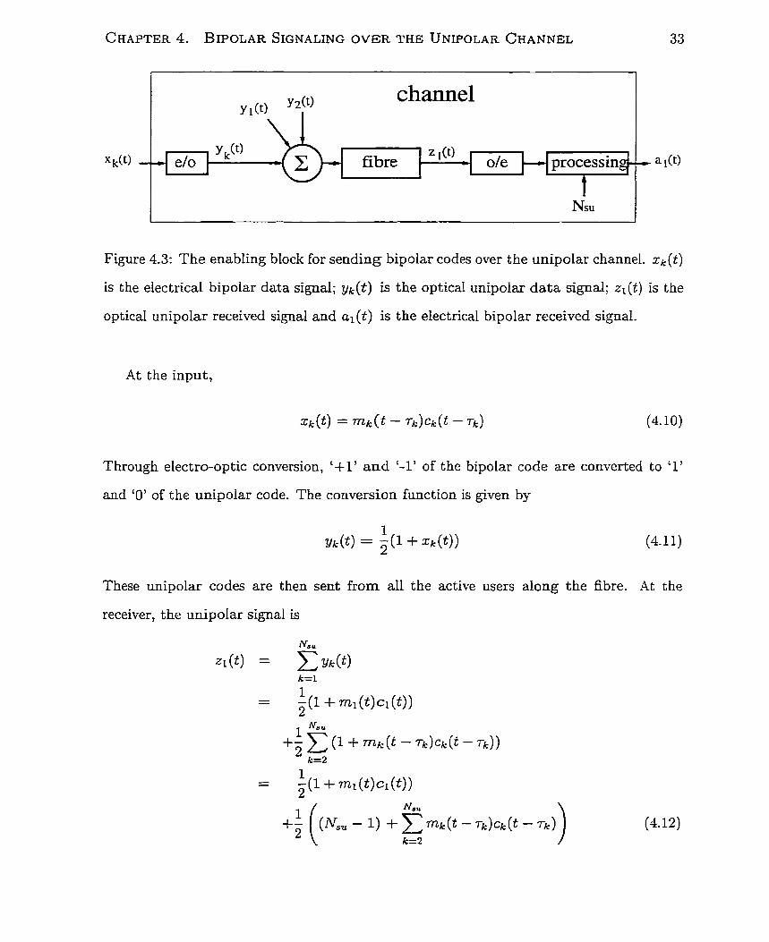
The enabling block for sending bipolar codes over the unipolar channel.
xk (t) is the electrical bipolar data signal; y k ( t ) is the optical unipolar data
signal; zl (t) is the optical unipolar received signal and al (t) is the electrical
. . . . . . . . . . . . . . . . . . . . . . . . . . . . bipolar received signal.
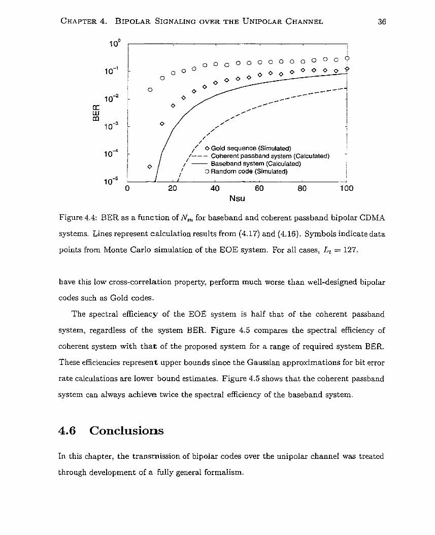
BER as a function of N,, for baseband and coherent passband bipolar
CDMA systems. Lines represent calculation results from (4.17) and (4.16).
Symbols indicate data points from Monte Carlo simulation of the EOE
system. For al1 cases, Lt = 127. . . . . . . . . . . . . . . . . . . . . . . .
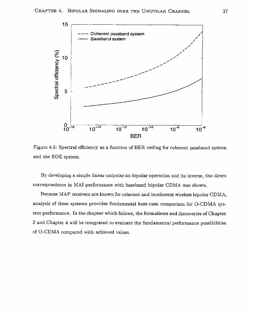
Spectral efficiency as a function of BER ceiling for coherent passband
. . . . . . . . . . . . . . . . . . . . . . . . . system and the EOE system.
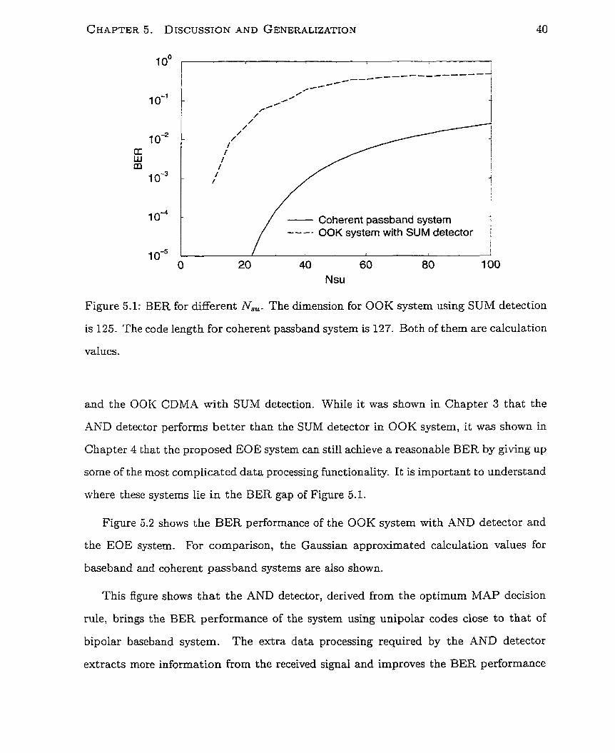
BER for different N,, . The dimension for OOK system using SUM detec-
tion is 125. The code length for coherent passband system is 127. Both of
. . . . . . . . . . . . . . . . . . . . . . . . . them are calculation values.
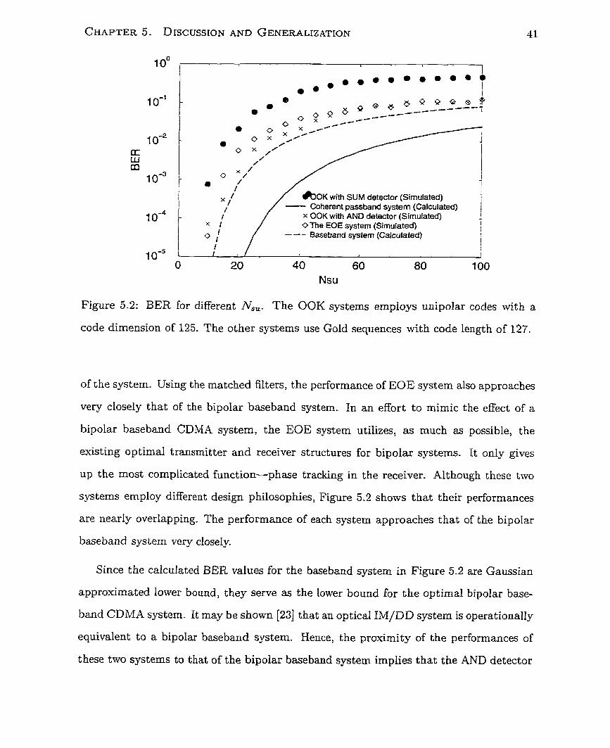
BER far different N,,. The OOK systems employs unipolar codes with a
code dimension of 125. The other systems use Gold sequences with code
. . . . . . . . . . . . . . . . . . . . . . . . . . . . . . . . . length of 127.
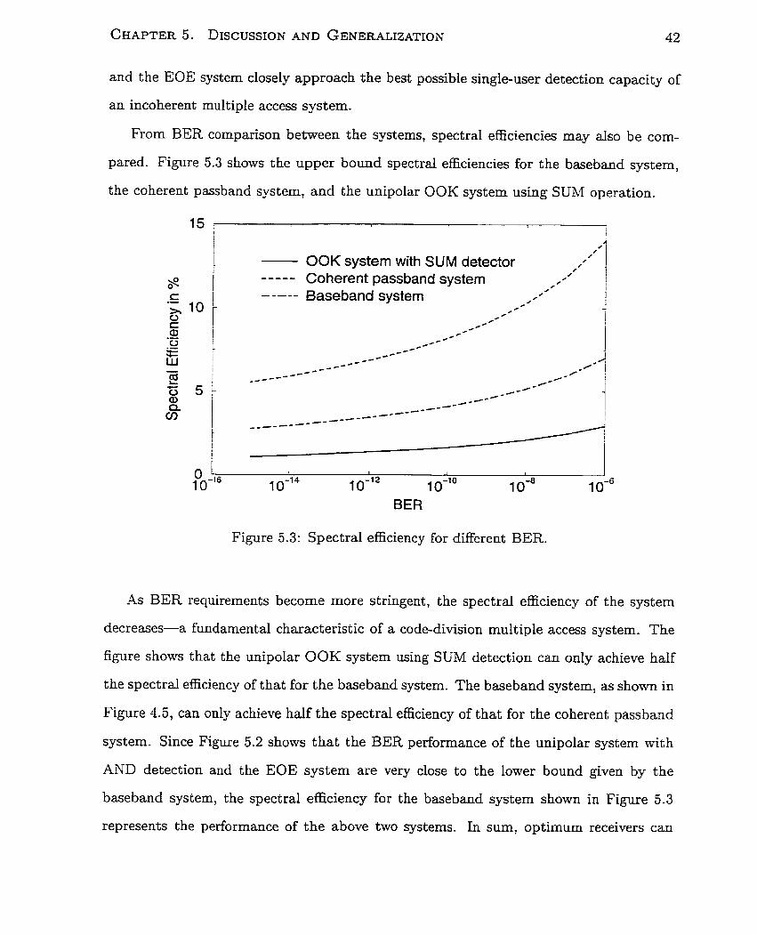
Spectral efficiency for different BER. . . . . . . . . . . . . . . . . . . . .
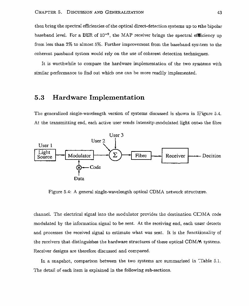
A general single-wavelength optical CDMA network structure. . . . .
Receiver structure for OOK system with AND detection. (a) Optical hard-
limiter is used. (b) Electrical hard-limiter is used. . . . . . . . . . . . . .
5-6 Receiver structure of the EOE system. After converting to electrical form
by the PjD, the received signal is amplified by 2 times and subtracted by
the N,, values. The resulting bipolar signal is correlated with the local
code through O I T phase shifter. Finally, a decision is made according to
the amount of charges accumulated over one bit period. . . . . . . . . . . 46
5 -7 Receiver struc$ure for multi-wavelength OOK system with AND detection.
(a) Optical hard-limiter is used. (b) Electrical hard-limiter is used. . . . 50
3.8 A multi-wavelength receiver structure for systems using 1-D codes. 1-D
codes are applied independently to the wavelength channels. Decisions are
made independently and in parallel in each wavelength channel. . . .. . 51
9 Flow chart for system selection . . . - . . . . . . . . . . . . . . . . . . . 52
List of Acronyms BER
SPSK
EOE
IM/DD
LAN
L P F
MAI
MAP
ML
MPR
MW-O-CDMA
MZ
O-CDMA
OOK
P D
SIK
SIR
TDMA
T/S AML
T/S SPR
WD MA
Bit error rate
Binary phase shift keying
Electro-optic/Opto-electronic
Intensity modulation/direct detection
Local area network
Low-pass filter
Multiple access int erference
Maximum a posteriori probability
Maximum likelihood
Multiple-puise-per row
Multi-wavelengt h optical code-division multiple access
Mach-Zehnder mo dulat or
Optical code-division multiple access
On-off keying
Photodetector
Shi& inversion keying
Signal to interference ratio
Time division multiple access
Temporal/spatial addition modulo Lt
Temporal/spatial single-pulse-per-row
Wavelength division multiple access

List of Symbols Dimension of the code
Energy contained in one bit
Temporal length of the code
blegabit per second
Number of simultaneous users
Number of wavelength used
Weight of the code
S p b o l sent to represent a bit "1"
Symbol sent to represent a bit "0"
xii
Chapter 1
Introduction
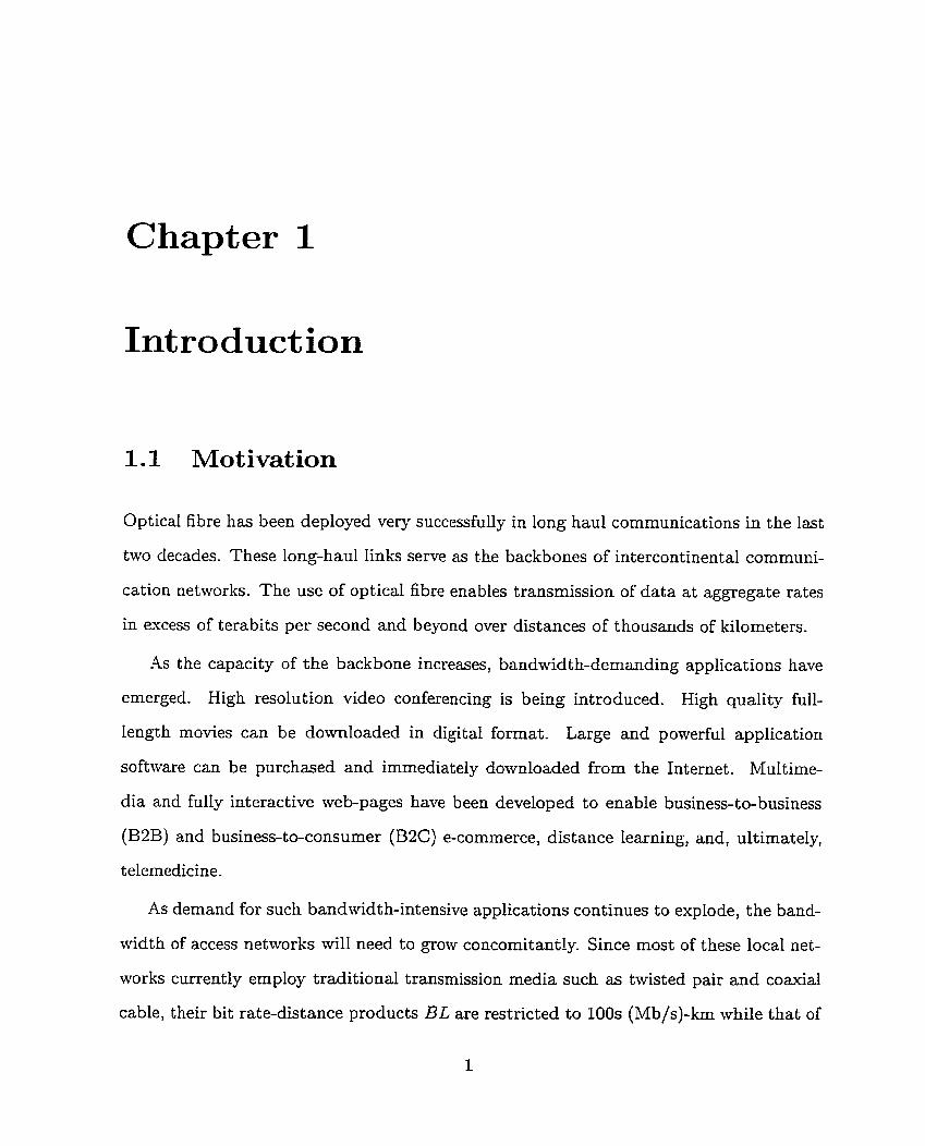
1.1 Motivation
Optical fibre h a . been deployed very successfully in long haul communications in the last
two decades. These long-haul links serve as the backbones of intercontinental communi-
cation networks. The use of optical fibre enables transmission of data at aggregate rates
in excess of terabits per second and beyond over distances of thousands of kilometers.
As the capacity of the backbone increases, bandwidth-demanding applications have
emerged. High resolution video conferencing is being introduced. High quality full-
length movies can be downloaded in digital format. Large and powerful application
software can be purchased and immediately downloaded from the Internet. Multime-
dia and fully interactive web-pages have been developed to enable business-to-business
(B2B) and business- to-consumer (B2C) e-commerce, distance learning, and, ult imat ely,
telemedicine.
As demand for such bandwidth-intensive applications continues to explode, the band-
width of access networks will need to grow concomitantly. Since most of these local net-
works currently employ traditional transmission media such as twisted pair and coaxial
cable, their bit rate-distance products BL are restricted to 100s (Mb/s)-km while that of
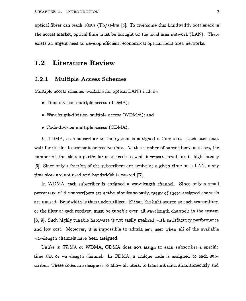
optical fibres can reach 1000s (Tb/$-km [5] . To overcome this bandwidth bottleneck in
the access market, optical fibre must be brought to the local area network (LAN). There
exists an urgent need to develop efficient, economrical optical local area networks.
1.2 Literature Review
1.2.1 Multiple Access Schemes
Multiple access schemes available for optical LA-Ws include
0 Time-division multiple access (TDMA) ;
0 Wavelength-division multiple access (WDM.4); and
0 Code-division multiple access (CDMA).
In TDMA, each subscriber to the system is azssigned a time slot. Each user must
wait for its slot to transmit or receive data. As t h e number of subscribers increases, the
number of time dots a particular user needs to wait increases, resulting in high latency
[6]. Since only a fraction of the subscribers are active at a given time on a LAN, many
time slots are not used and bandwidth is wasted [7].
In WDMA, each subscriber is assigned a wawelength channel. Since only a small
percentage of the subscribers are active simultaneously, many of these assigned channels
are unused. Bandwidth is thus underutilized. Either the light source a t each transmitter,
or the filter at each receiver, must be tunable over al1 wavelength channels in the system
[8, 91. Such highly tunable hardware is not easily realized with satisfactory performance
and low cost. Moreover, it is impossible to admiit new user when al1 of the available
wavelength channels have been assigned.
Unlike in TDMA or WDMA, CDMA does no-t assign to each subscriber a specific
time slot or wavelength channel. In CDMA, a unique code is assigned to each sub-
scriber. These codes are designed to allow al1 users to transmit data simultaneously and
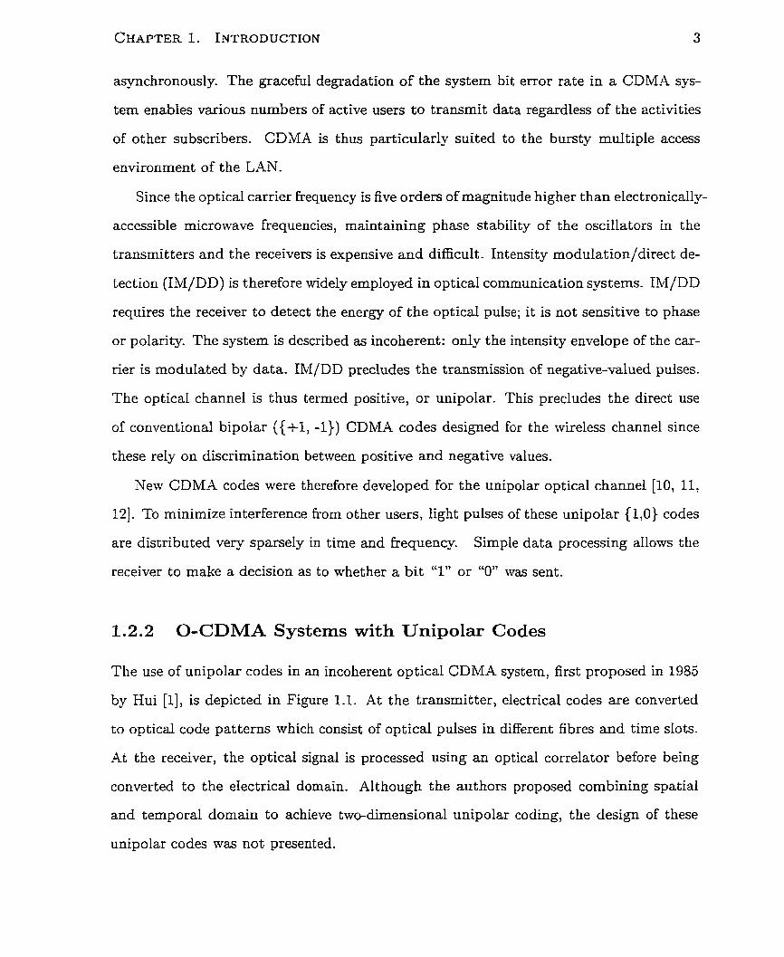
asynchronously. The graceful degradation of the system bit error rate in a CDMA sys-
tem enables various numbers of active users to transmit data regardless of the activities
of other subscribers. CDMA is thus particularly suited to the bursty multiple access
environment of the LAN.
Since the optical carrier frequency is five orders of magnitude higher than electronically-
accessible microwave frequencies, maintaining phase stability of the oscillators in the
transmitters and the receivers is expensive and difficult. Intensity modulation/direct de-
tection (IM/DD) is therefore widely employed in optical communication systems. IM/DD
requires the receiver to detect the energy of the optical pulse; it is not sensitive to phase
or polarity. The systern is described as incoherent: only the intensity envelope of the car-
rier is rnodulated by data. IM/DD precludes the transmission of negative-valued pulses.
The optical channel is thus termed positive, or unipolar. This precludes the direct use
of conventional bipolar ({fl, -1)) CDMA codes designed for the wireless channel since
these rely on discrimination between positive and negative values.
New CDMA codes were therefore developed for the unipolar optical channel [ I O , 11,
121. To minimize interference from other users, light pulses of these unipolar {1,0) codes
are distributed very sparsely in time and frequency. Simple data processing allows the
receiver to make a decision as to whether a bit "1" or "0" was sent.
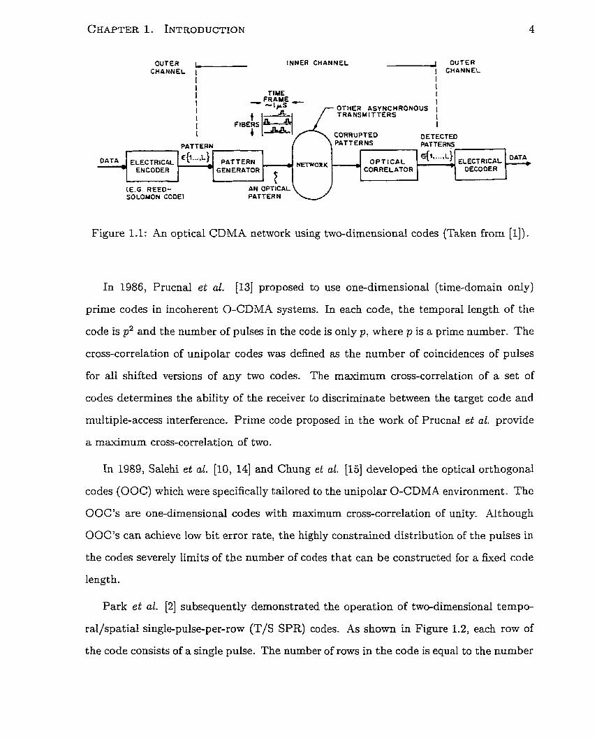
1.2.2 O-CDMA Systems with Unipolar Codes
The use of unipolar codes in an incoherent optical CDMA system, first proposed in 1985
by Hui [l], is depicted in Figure 1.1. At the transmitter, electrical codes are converted
to optical code patterns which consist of optical pulses in different fibres and time slots.
At the receiver, the optical signal is processed using an optical correlator before being
converted to the electrical domain. Alt hough the authors proposed combining spatial
and temporal domain to achieve two-dimensional unipolar coding, the design of these
unipolar codes was not presented.
OUTER I_ [NNER CUANNEL 1 OUTER CHANNEL 1 1 CHANNEL
I I
(CG. REED- SOLOMON CODE)
I I I TIME I
I I 1 OTHER ASYNCHRONOUS 1 I TRANSMITTERS I 1 I I CORRUPT €0 DETECTED
PATTERN PATTERNS PATTEFI+
Figure 1.1: An optical CDMA network using two-dimensional codes (Taken from [II).
In 1986, Prucnal et al. [13] proposed to use one-dimensional (time-domain only)
prime codes in incoherent O-CDMA systems. In each code, the temporal length of the
code is p2 and the number of pulses in the code is only p, where p is a prime number. The
cross-correlation of unipolar codes was defined as the number of coincidences of pulses
for al1 shifted versions of any two codes. The maximum cross-correlation of a set of
codes determines the ability of the receiver to discriminate between the target code and
multiple-access interference. Prime code proposed in the work of Prucnal et al. provide
a maximum cross-correlation of two.
OAT:
In 1989, Salehi et al. [IO, 141 and Chung et al. [15] developed the optical orthogonal
codes (O OC) which were specifically tailored to the unipolar O-CDMA environment. The
O 0 C's are one-dimensional codes wit h maximum cross-correlation of unity. Alt hough
OOC's can achieve low bit error rate, the highly constrained distribution of the pulses in
the codes severely b i t s of the number of codes that can be constructed for a fixed code
length.
Park et al. [2] subsequently demonstrated the operation of two-dimensional tempo-
rallspatial single-pulse-per-row (T/S SPR) codes. As shown in Figure 1.2, each row of
the code consists of a single pulse. The number of rows in the code is equal to the number
. f ~ " - - - ' L ~ ' DATA ' ELECTRICAL ,
C{~--.*L) PATTERN + M O R K
GENERATOR ELECTRIC4L
ENCOOER O P T I C A L ' '
CORRELATOR DECOOER
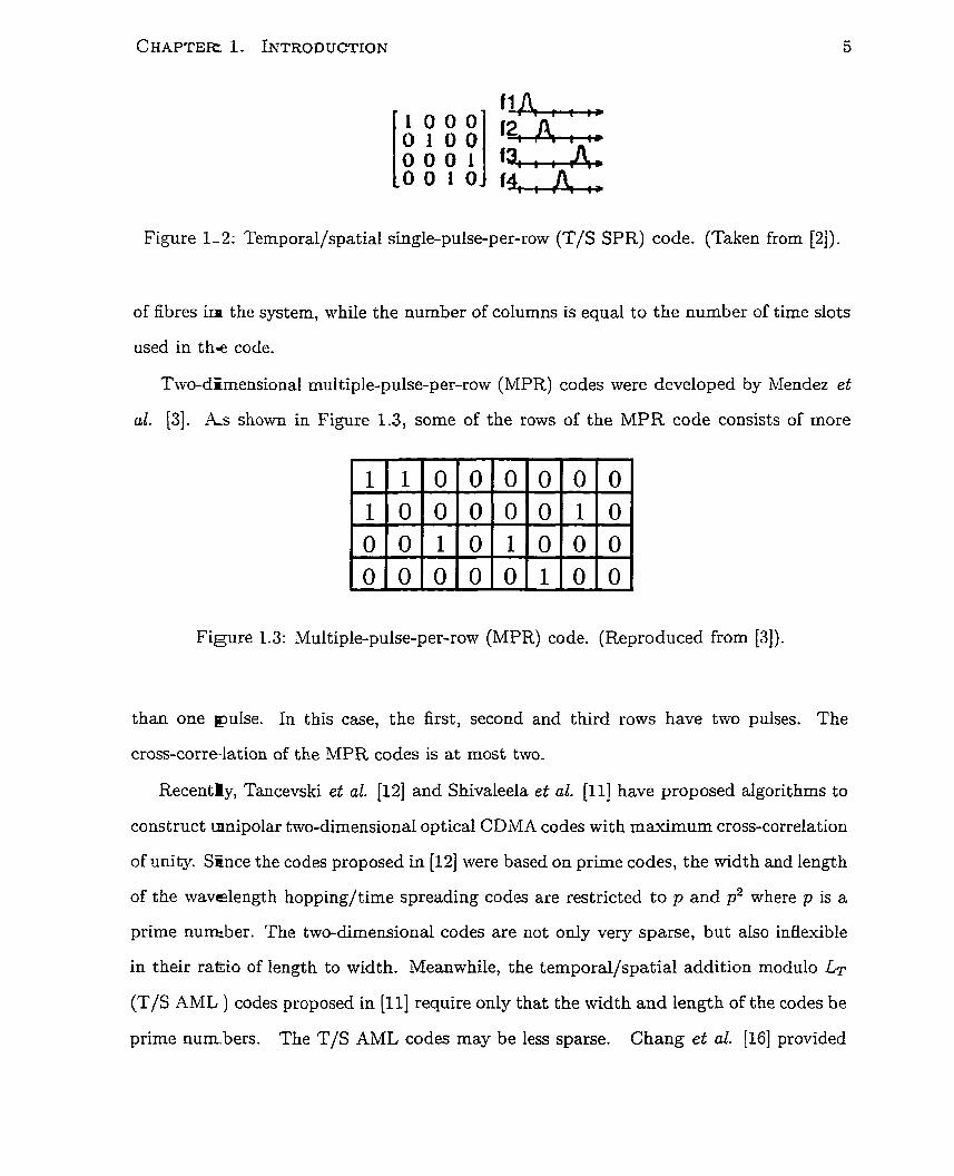
Figure 1-2: Temporal/spatial single-pulse-per-row (T/S SPR) code. (Taken from [2j).
of fibres i n the system, while the number of columns is equal to the number of time slots
used in t h e code.
Swo-dErnensiona.1 multiple-pulse-per-row (MPR) codes were developed by Mendez et
al. [3]. As shown in Figure 1.3, some of the rows of the MPR code consists of more
Figure 1.3: Multiple-pulse-per-ronr (MPR) code. (Reproduced from [3]).
than one pulse. In this case, the first, second and third rows have two pulses. The
cross-correlation of the MPR codes is at most two.
Recently, Tancevski et al. [12] and Shivaleela et al. [Il] have proposed algorithms to
construct mnipolar two-dimensional optical CDMA codes with maximum cross-correlation
of unity. SÈnce the codes proposed in [12] were based on prime codes, the width and length
of the wavelength hoppingltime spreading codes are restricted to p and p2 where p is a
prime nuneber. The two-dimensional codes are not only very sparse, but also inflexible
in their ra&io of length to width. Meanwhile, the temporal/spatial addition modulo Lr
(T/S AML ) codes proposed in [Il] require only that the width and length of the codes be
prime numbers. The T/S AML codes may be less sparse. Chang et al. [16] provided
a detailed analysis of the spectral efficiency of these T/S AML codes for different BER
requirements. The spectral efficiency is defined as the ratio of aggregate number of bits
that can be sent to the amount of bandwidth occupied. It is shown in [16] that, as the
system BER requirement becomes more stnngent, the spectral efficiency of t be system
drops. The peak spectral efficiency for a system BER of IO-* is about 5%, while that
for a system BER of 10-' drops to below 2%. The authors found that even the best
unipolar codes designed over the last decade can only achieve a spectral efficiency of a
few percent.
Although the above systems can achieve low BER over the unipolar optical channel
usine; sparse codes, their spectral efficiencies are very low and have neither been explored
nor optimized frorn a communication theoret ic perspective.
1.2.3 O-CDMA Systems with Bipolar Codes
In parallel with the development of unipolar codes, researchers have explored the possibil-
ity of adopting t o the unipolar channel the bipolar codes developed for wireless networks.
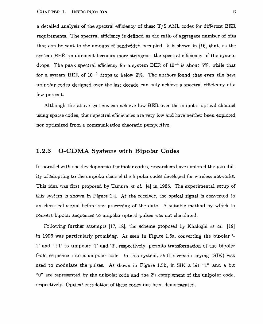
This idea was first proposed by Tamura et al. [4] in 1985. The experimental setup of
this system is shown in Figure 1.4. At the receiver, the optical signal is converted to
an electrical signal before any processing of the data. A suitable method by which to
convert bipolar sequences to unipolar optical pulses was not elucidated.
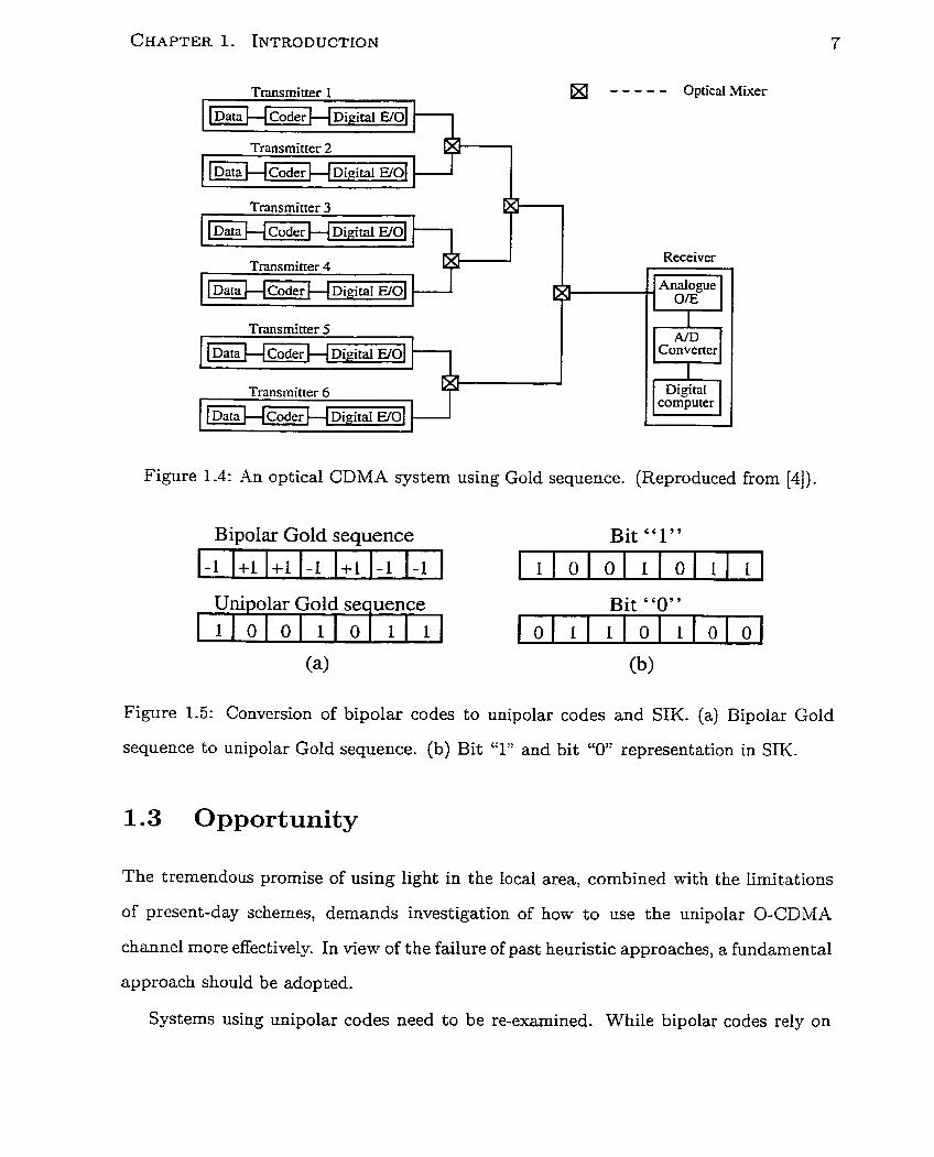
Following further attempts [17, 181, the scheme proposed by Khaleghi et al. (191
in 1996 was particularly prornising. As seen in Figure 1.5a, converting the bipolar '-
1' and '+1' to unipolar '1' and 'O', respectively, permit~ transformation of the bipolar
Gold sequence into a unipolar code. In this system, shift inversion keying (SIK) was
used to modulate the pulses. As shown in Figure 1.5b, in SIK a bit "1" and a bit
"O" are represented by the unipolar code and the 2's complement of the unipolar code,
respect ively. Opt ical correlation of these codes has been demonstrated.
Transmitter 1 I
- - - - - Optical Mixer
Transmitter 2
1 ~ a t a H coder H D F ~
Transmitter 3 I J
Receiver Transmitter 4
1 Data Cl coder H Digital .
Transmitter 5
Transmitter 6
I H ~ o d e r H Digital EIOI
Y i q Converter
Figure 1.4: An optical CDMA system using Gold sequence. (Reproduced from [4]).
Bi~olar Gold seauence Bit "1"
Unipolar Gold secuence Bit "O" 1 l O l O l l l O
Figure 1.5: Conversion of bipolar codes to unipolar codes and S N . (a) Bipolar Gold
sequence to unipolar Gold sequence. (b) Bit Y" and bit "O" representation in SIK.
1 1 1
1.3 Opportunity
(a)
The tremendous promise of using light in the local area, combined with the limitations
of present-day schernes, demands investigation of how to use the unipolar O-CDMA
channel more effectively. In view of the failure of past heuristic approaches, a fundamental
approach should be adopted.
Systems using unipolar codes need to be re-examined. While bipolar codes rely on
cancellation between positive and negative pulses to minimize cross-correlation, unipolar
codes rely on a sparse distribution of pulses to avoid coincidence and minimize cross-
correlation. These systems deserve careful re-examination from a communications theo-
ret ic perspective wit h a view to optimizing t heir spectral efficiencies.
Khaleghi's result motivates fundamental exploration of the use of bipolar codes over
the unipolar optical chânnel. The effect of bipolarity may be reproduced in the unipolar
channel. The well-designed codes developed for wireless networks rnay be applied to the
unipolar optical channel. The spectral efficiencies of systems using bipolar codes must be
compared with those using unipolar codes, enabling determination of the fundamental
performance possibilities in incoherent optical CDMA systems.
1.4 Thesis Structure
The goal of this thesis is to deteïmine the upper bound for the spectral efficiency of
an incoherent optical CDMA system using single-user detection and to show how this
limit can be practically approached by novel system design. In Chapter 2, the analytical
framework employed throughout this work is laid out. The structure of the networks,
the codes used, and the relevant assumptions are detailed. The simulation tool used
in this work is also introduced. In Chapter 3, the optimum decision rule is derived for
sys tems using unipolar codes. Spectral efficiency is contrasted between the system using
this optimum decision rule with that using the conventional method. In Chapter 4, the
use of bipolar codes over the unipolar channei is investigated. The spectral efficiency
resulting from the case of this technique is compared with that of a coherent bipolar
channel. In Chapter 5, the bit error rate is compared for unipolar and bipolar coded
systems. Hardware implementation aspects of these systems are also compared. The
thesis concludes in Chapter 6 with a summary of the important results and directions
for future work.

Chapter 2
Analyt ic Framework
2.1 Introduction
Before analyzing the system whose performance is to be explored and improved in the
present work, it is first necessary to define the analytical framework employed herein.
In the present chapter, structure of the communication network and the CDM-4 codes
employed are detailed. The tools used to estimate the BER performance of the network
under different traffic conditions are also introduced.
2.2 System Architecture and Assumptions
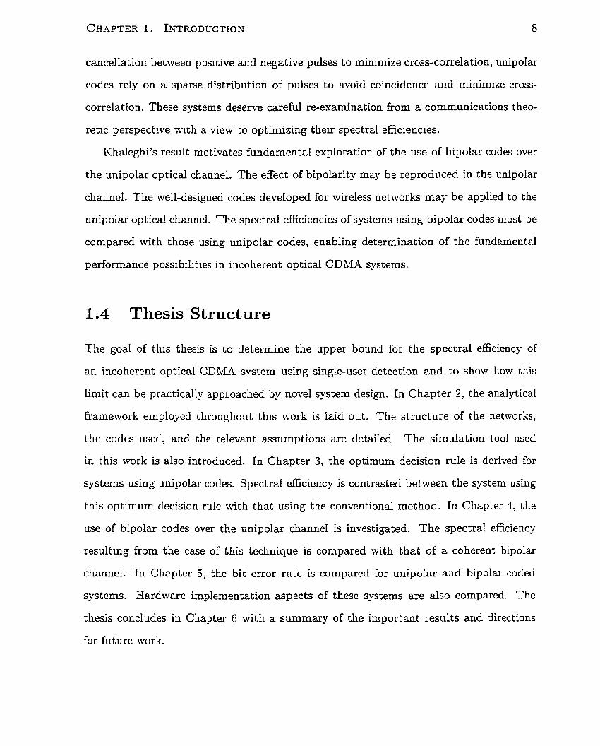
.A star network topology shown in Figure 2.1 is considered throughout this work. Each
user has a transmitter and a receiver. The star coupler collects the power sent by the
transmitters and distributes it equally among al1 receivers.
In this broadcast and select network, optical code-division multiple access (O-CDMA)
enables multiple users to share simultaneously the available bandwidth. Usets are distin-
guished by code, instead of by a time slot as in TDMA or a frequency as in FDMA/WDM.4.
Since no fixed resource is assigned to each user, CDMA is well suited to the bursty traffic
environment of a LAN. Since no synchronization among the transmitters is required in
Star Coupler Tram mi tter # 1 Receiver #l
Transmitter #2 Receiver#2
Transrnitter #3 Receiver #3
Figure 2.1: The optical L.kN using star topology
O-CDMA systerns, no user needs to wait for its turn to transmit data. CDMA does not
strictly limit the number of active users it can support: the error performance of the
system degrades gracefully as the nurnber of active users increases.
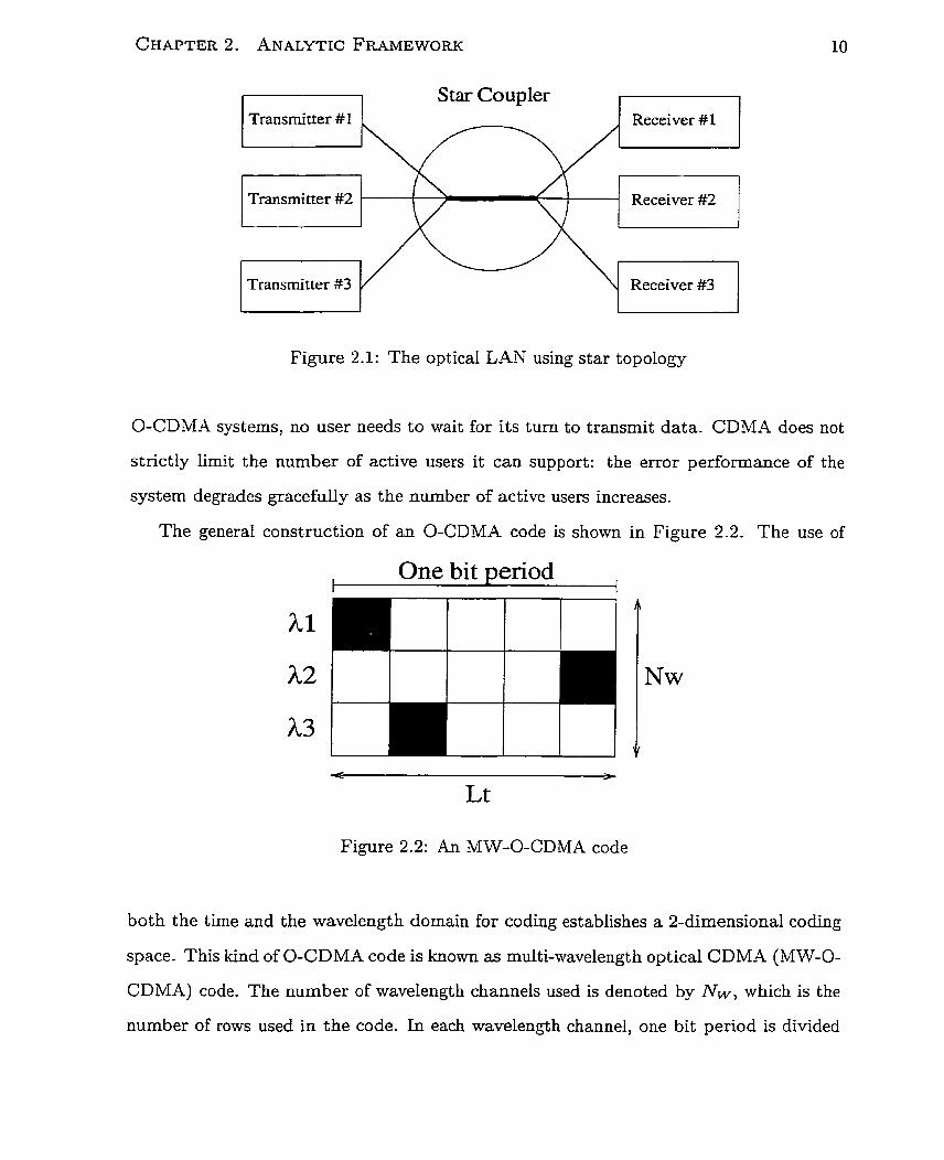
The general construction of an O-CDMA code is shown in Figure 2.2. The use of
One bit ~ e n o d
Figure 2-2: An MW-O-CDMA code
bot h the time and the wavelength domain for coding establishes a 2-dimensional coding
space. This kind of O-CDMA code is known as multi-wavelength optical CDMA (MW-O-
CDMA) code. The number of wavelength channels used is denoted by Nw, which is the
number of rows used in the code. In each wavelength channel, one bit period is divided
into Lt time slots. Lt is the temporal length of the code since it indicates the number of
chips available in a bit period per wavelength. The coding area D is the product of -VLv
and Lt, which also gives the total number of available chips. The weight W of the code
is the number of chips in which a light pulse is present. These are called the '1' chips of
the code. The density of the code is the ratio of code weight to coding area 5. Light pulses transmitted by different users may overlap in the star coupler. As the
light source in each transmitter is assumed to be incoherent, the total intensity a t a chip
is the sum of the intensities of the individual light pulses existing in that chip.
The codes are designed to be sufficiently different that the probability of mistaking
one code for another is very low. However, when many users are actively transmitting,
rnany overlaps may result. A receiver may then erroneously conclude that its target
code was sent. This phenomenon is knom as an error arising due to multiple access
interference (MAI). As more users share the channel simultaneously, the effect of MAI
becomes more significant.
Although physical noise effects are important for error performance in many optical
communication systems, these effects can increase or decrease the level of a pulse by only a
fraction of its value. MAI, in contrast, increases the level of a pulse by integer multiples
of the original pulse level. VVhen the pulse power is high and the photodetectors are
suitably Iow-noise, Wf AI is the dominant cause of performance degradation in O-CDMA
systems. The focus of the present work is on the impact of MAI on error performance.
In the present work, chip synchronization among al1 transmitters is assurned- This
provides a worst-case estimate of the performance of what is in reality a fully asyn-
chronous system which only requires chip synchronization between the source transmitter
and the t arget receiver [l O].
Both random codes and deterministic codes are considered herein. In the random
case, light pulses are placed randomly in W of the D chips available. In the deterministic
case, locations of the W light pulses are carefully chosen to minimized cross-correlations
among codes. Though deterministic codes perfom better t han random codes in an MAI-
limited environment, the improvement in error performance of deterministic over random
codes may not justify the added design and management effort. It is therefore worthwhile
to explore the performance of both deterministic codes and random codes.
2.3 Simulation Tool
In addition to presenting closed-form analysis, the present work makes use of Monte Carlo
simulation. This statistical simulation tool generates stochasticaliy the trafic pattern of
the network, closeiy mimicking the performance of a real system. This approach makes
it possible to:
1. Verify analytical results. Since Pd onte Carlo simulation mirnics directly the system
in operation, it is an independent method of determining the BER of the system.
2. Estimate the system performance when it is difficult to analyze through closed-form
analysis. Analytical methods become especially complex in CDMA systems when
the correlation properties between the codes are taken into account in determining
the optimal detection algorithm. In this case, Monte Carlo simulation is a suitable
tool for measuring the performance of such systems.
In general, the Monte Carlo simulation algorithms used in this work consists of the
following steps:
1. Within the set of codes (random or deterministic), the subset of codes to be sent
by the transmitters is selected a t random.
2. For two consecutive bit periods, the bit pattern to be sent by each of the selected
transmitters is generated randomly. Since the transmitters are chip synchronized,
instead of bit synchronized, the code chips sent by a transmitter may overlap with
those sent by other transniitters during a subsequent bit period. Thus, generating
data pattern for two consecutive bit periods allows modeling of the effect of MAI
given bit asynchronous operation.
3. For each transmitter, a delay is randomly assigned relative to the target receiver.
4. At the target receiver, the superposition of the transmitted signal is detected.
5. At the target receiver, a decision rule is applied as to whether bit "1" or bit "0"
was sent.
6. At the end of each bit period, the decision made by the target receiver is compared
with the transmitted bit to determine whether a bit error was made.
2.4 Summary
This chapter has presented the analytical framework which will be used for the analysis
in subsequent chapters. The network is assumed to be a broadcast and select network in
which O-CDMA is used as the multiple access technique. The codes used in this O-CDMA
system utilize both the time and fiequency domains so that the coding space is two-
dimensional. Deterministic and randorn codes are considered herein. The impact of the
key mechanism which dominates performance degradation, multiple access interference, is
st udied in t his work. In addition to analytical calculations based on probabilistic models,
the BER performance of the system is also explored through Monte Carlo simulations
which are based on random generations of network traffic. This tool serves not only to
veriQ analytical calculations, but also to evaluate system performance when closed form
analysis becomes cumbersome.
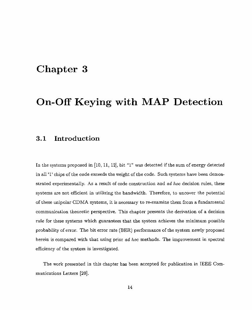
Chapter 3
On-Off Keying with MAP Detection
3.1 Introduction
In the systems proposed in [IO, 11, 121, bit "1" was detected if the sum of energy detected
in al1 '1' chips of the code exceeds the weight of the code. Such systems have been demon-
strated experimentally. As a result of code construction and ad hoc decision rules, these
systems are not efficient in utilizing the bandwidth. Therefore, to uncover the potential
of these unipolar CDMA systems, it is necessary to re-examine them from a fundamental
communication theoretic perspective. This chapter presents the derivation of a decision
rule for these systems which guarantees that the system achieves the minimum possible
probability of error. The bit error rate (BER) performance of the system newly proposed
herein is compared with that using prior ad hoc methods. The improvement in spectral
efficiency of the system is investigated.
The work presented in this chapter has been accepted for publication in IEEE Corn-
munications Letters [20].
CHAPTER 3. ON-OFF KEYING WITH MAP DETECTION
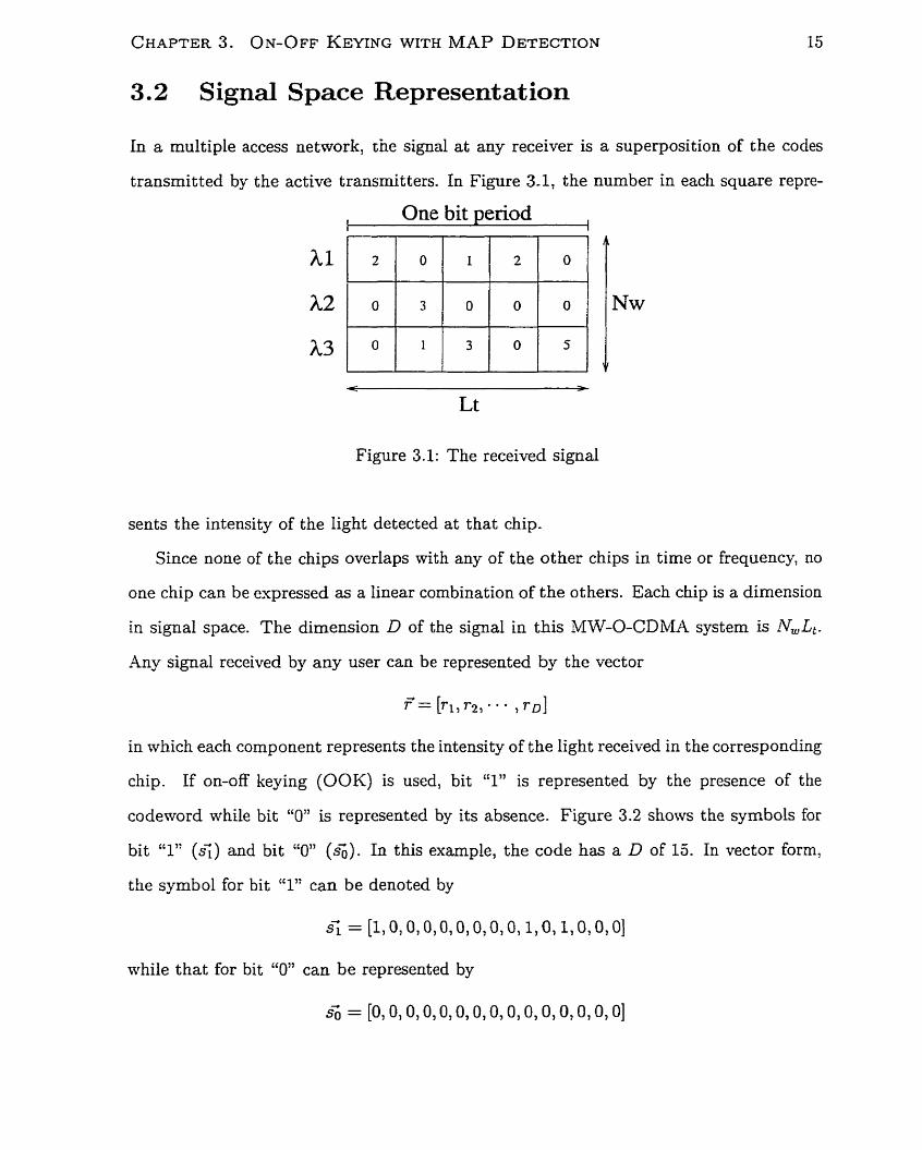
3.2 Signal Space Representat ion
In a multiple access network, crie signal at any receiver is a superposition of the codes
transmitted by the active transmitters. In Figure 3.1, the number in each square repre-
I One bit period
I
-
Lt
Figure 3.1: The received signal
sents the intensity of the Iight detected at that chip-
Since none of the chips overlaps with any of the other chips in time or frequency, no
one chip can be expressed as a linear combination of the others. Each chip is a dimension
in signal space. The dimension D of the signal in this MW-O-CDMA system is N,Lt.
Any signal received by any user can be represented by the vector
in which each component represents the intensity of the light received in the corresponding
chip. If on-off keying (OOK) is used, bit "1" is represented by the presence of the
codeword while bit "0" is represented by its absence. Figure 3.2 shows the symbols for
bit "1" (s;) and bit "0" (s;). In this example, the code has a D of 15. In vector form,
the symbol for bit "1" can be denoted by
while that for bit "0" can be represented by
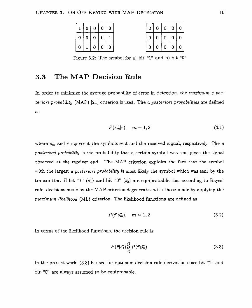
CHAPTER 3. ON-OFF KEYING WITH MAP DETECTION
Figure 3.2: The symbol for a) bit
3.3 The MAP Decision Rule
:'Y and b) bit "O"
In order to minirnize the average probability of error in detection, the maximum a pos-
t er ior i probability (MAP) [21] critenon is used. The a poste7%ori probabilities are defined
as
where s; and r' represent the syrnbols sent and the received signal, respectively. The a
posteriori probability is the probability that a certain symbol was sent given the signal
observed a t the receiver end. The MAP criterion exploits the fact that the symbol
with the largest a posteriori probability is most Likely the symbol which was sent by the
transmitter. If bit "1" (si) and bit "O" (si) are equiprobable the, according to Bayes7
rule, decisions made by the MAP criterion degenerates with those made by applying the
maximum likelihood (ML) criterion. The Iikelihood functions are defined as
( s ) rn = l,2
In terms of the Iikelihood functions, the decision rule is
In the present work, (3.3) is used for optimum decision rule derivation since bit "1" and
bit "O" are always assumed to be equiprobable.
CHAPTER 3. ON-OFF KEYING WITH MAP DETECT~ON
3.4 Decision Rule Derivat ion
To be consistent with the system discussed in [IO] and [16], the OOK modulation scheme
is considered. If the received light intensity at any chip is independent of that at any
other chip, the probability in (3.3) may be expressed as
This assumption is valid under the following conditions:
1. Random codes. Since the codes are randomly generated with a uniform distribution,
the probability that a '1' chip of a code is present in any of the unused chips is the
same.
2. In case of deterministic codes, the receiver does not know, or does not take into
account, the algorithmic constructions of other users7 codes in the system. The
receiver can only assume the presence of a pulse at a certain chip does not affect
the probability of the presence of a pulse at any other chip.
Under the above conditions, the probability that a puIse from any other active user
falls on a particular chip is g. The factor of accounts for the fact tha t only half of the
time does a user send a bit "1". The light intensity at a chip determines the number of
other users overIapping at this chip. Since the user transrnitting a bit does not send
any pulse, the component likelihood functions when a bit "0" was sent are given by:
where N,, is the number of active users in the network.
When a bit "1" was sent, optical pulses are only present a t the '1' chips of the code.
Hence, the component likelihood functions for the other chips can also be expressed by
(3.5). Since an optical pdse is sent by the transmitting user at each of the '1' chip, the
CHAPTER 3. ON-OFF KEYING WITH MAP DETECTION
component likelihood fiinctions for t hese chips are
where j denotes a '1' chip of the code. For ease of cornparison with (3.51, (3.6) can be
Using ( 3 . 4 , the likelihood functions on both sides of (3.3) can be expressed as
k= 1
D-W W
Since the product in (3.8) includes al1 of the terms in the first product in (3.9), (3.3) can
be expressed as
By (3.5) and ( 3 3 , (3.10) becomes
Rearranging (3.1 1) gives
Simplifying the two combiratorial terms on the left hand side of (3.12), the decision rule
becomes
CHAPTER 3. ON-OFF KEYING WITH MAP DETECTION 19
Since the rïght hand side of (3.13) is fixed for a given code constmcrtion, (3.13) rep-
resents a threshold operation with the threshold value on the right handi side.
This decision rule only requires knowledge of the received light intensirties at the FV '1'
chips of the code, although al1 of the chips are involved from the beginnin;.g in (3.4). Since
the component likelihood functions for the rest of the chips are the s ame regardless of
whether a bit "1" or a bit "0" was sent, these probability terms cancel dumng cornparison
through (3.3). The observations at these chips are thus not used during detection.
The decision rule shows that the smaller the left hand side, the more likely the received
signal is a bit "1". In other mords, the larger the values of rj, the Wgher the light
intensities are at the '1' chips of the code, the more likely it is a si. The largest value of
the left hand side is infinity when there is at least one rj equals to O. I n this case, the
decision is so. The largest finite value of the left hand side occurs when au of the T j are
1. In this case, the decision rule (3.13) becomes
From (3.14) , two decision-making regimes are observed.
N u < (g - 1)
When the number of active users is less than ($ - l) , the decision made from
(3.13) is si as long as the light intensity levels of al1 the '1' chips of the code are
at least 1. This is equivalent to carrying out a logical AND operation on al1 the '1'
chips of the code. In this regime, decision-making only requires knowledge of light
intensities at the W '1' chips of the code. Although N, appears in the decision
rule in (3.13): its value is not required for making decision.
NSu > ($ - 1)
When the number of active users gets beyond (F - l), the decision by (3.13) must
involve the value of Nsu. (3.14) shows that the detector can still announce an s<
CHAPTER 3. ON-OFF KEYING WITH MAP DETECTION 20
when al1 the '1' chips of the code have light intensities of '1'. In this high multiple-
access interference environment, a few '2's are needed for the detector to announce
an si. -4s ATs, increases, a higher intensity level is required at each '1' chip of the
code to make a decision of si. Thus, the detector is no longer a pure AND operator
in t his regime .
For most deterrninistic codes with acceptable BER performance, N', cannot normally
exceed (g - 1) since ($ - 1) is larger than the cardinality (maximum size of the set
of codes that obeys the constraints) of most deterministic MW-O-CDMA codes with
maximum cross correlation of one [22]. Usudy, only the first regirne is applicable for
deterministic codes. Accordingly, an AND operator is suficient for most deterministic
codes used in the O-CDMA system. On the other hand, when random code is used, the
number of active users in the system may exceed ($$ - 1) since the cardinality of the
random code is (gz:) times larger than the inverse of code density 6. Both regimes of
operation are thus possible for the random code. Although the threshold requires frequent
adjustment as N,, increases in the second regime, Figure 3.3 shows that involving IV,, in
making decision can only improve the BER by a small fraction of an order of magnitude.
An AND operator usually suffices for the random code-
From the above analysis, the MAP detector for the MW-O-CDMA system using
OOK is essentially equivalent to a logical AND operator. It is the optimum single-user
detector for systems using random codes. This is also true for systems using well-designed
deterministic codes if the code construction and the correlation properties of the codes
are ignored by the receiver in making a decision. It is thus shom for the first tirne in
this work that the AND decision rule is optimal for the MW-O-CDMA system.
In most proposed systems [I l , 121, detection is accomplished by thresholding the sum
of the light intensities detected at al1 of the '1' chips of the code. Individual light intensity
at each '1' chip is not accounted for in coming to a decision.
CHAPTER 3. ON-OFF KEYING WITH MAP DETECTION 21
In the sections which follow, the conventional detector is referred as the SUM detector,
while that described by (3.13) is c a e d the AND detector.
3.5 Performance Analysis
In OOK, since each symbol represents only one bit, the probability of symbol error is
equal to the bit error rate- If 6 and 6 are equiprobable, the BER is
1 1 BER = -P(e(s;) f ,P(els<)
2 d
For a system using an AND detector with OOK, (3.13) gives the decision rule. When
an sf was sent, the light intensity detected a t each of the W '1' chips must be at least
1. Thus, P(els;) = O in (3.15). The probability in the second term accounts for the
probability of detecting a si when a so was sent, the probability that pulses sent by
other users cause every '1' chip of the code to have a light intensity of at least '1'.
The analytical expression for this would resemble (3.8) except that in each '1' chip, the
component likelihood functions must be summed from r k = 1 to r k = N,, - 1. (3.15)
t herefore becomes
Since al1 of the terms in the summation are independent of j, (3.16) can be further
simplified to
For the SUM detector, the decision rule would be
When a bit "1" was sent, the light intensity detected a t each '1' chip of the code must
be at Ieast 1. The sum of the light intensity a t each of the W '1' chips rnust therefore be
CHAPTER 3- ON-OFF KEYING WITH M-4P DETECTION 22
at least bV and P(elsi) = O in (3.15). The BER for this conventional detector simplifies
to the probability that at least PV pulses fiom other users to faIl on the W '1' chips. If
the total number of active users in the system is N,,, the maximum number of pulses
present in the system is W(N, - 1). Since only half of the cime is each pulse present in
the system, the probability of a pulse from an interfering user f a l h g in an'; one of the
PV '1' chips is g. The probability that there are i pulses in the W '1' chips is
The BER for the SUM detector is
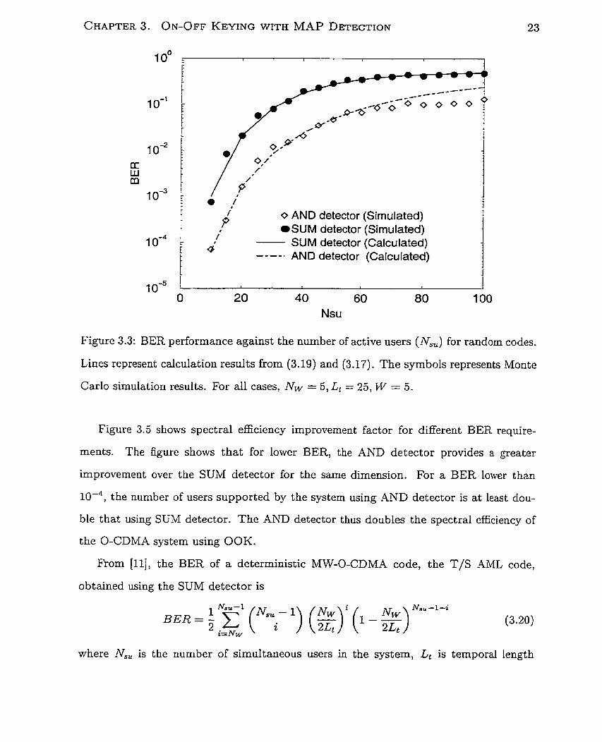
The BER performances calculated from (3.17) and (3.19) are shown in Figure 3.3
(lines). Monte Carlo simulation results are shown on the same plot (symbols). The
simulation results confirm the equations developed for both the SUM and AND detectors.
Figure 3.3 shows that the BER performance of the AND detector always exceeds that
of the SUM detector. For the same BER requirement and dimension, the .4ND detector
can always support more users than the SUM detector. Thus, the spectral efficiency
defined in [16] is increased. Figure 3.3 also shows the slight insufficiency of using the
pure AND detector when the number of active users Nsu is greater than (g - 1). When
Ai,, exceeds 50, with (g - 1) = 49, the BER obtained by strict application of the decision
rule of (3.13) is lower than that obtained from the simplified (3.17).
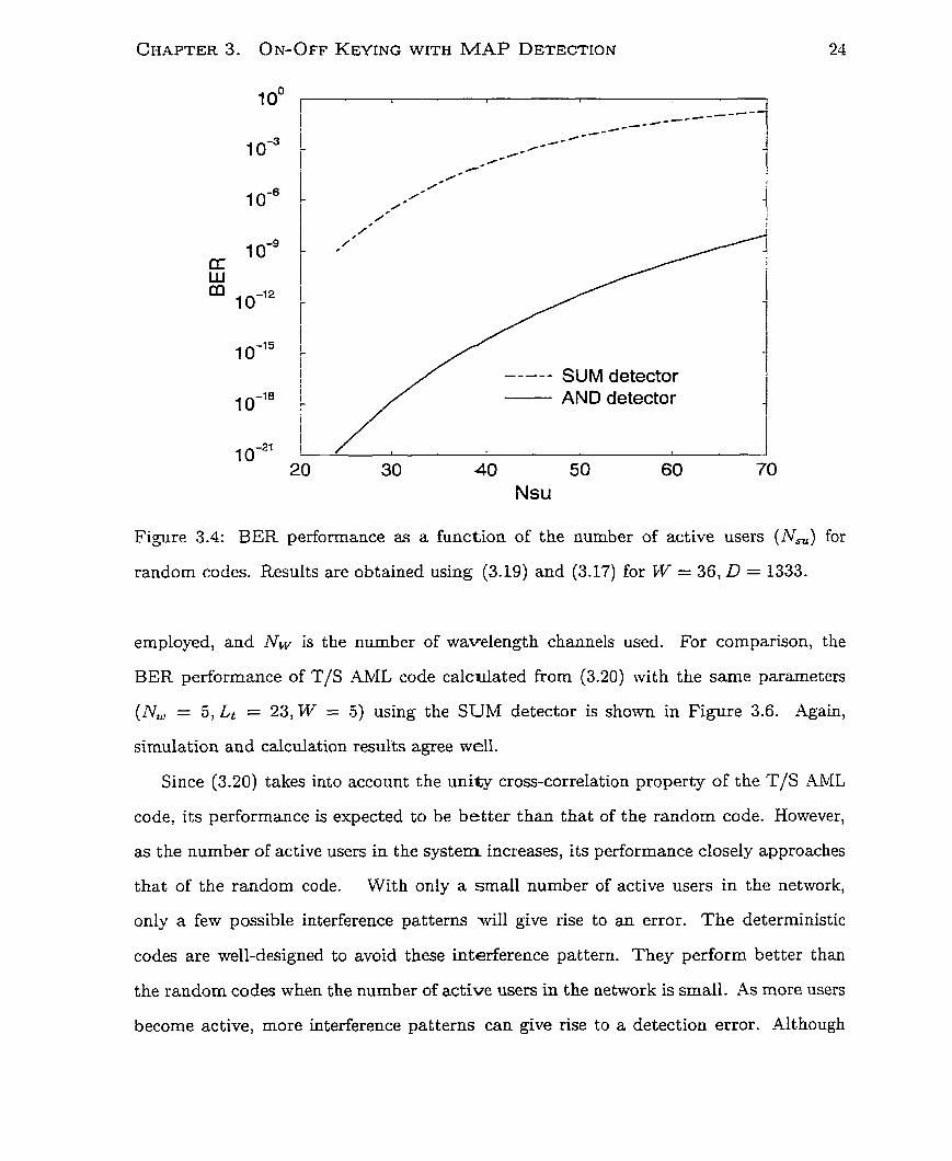
(3.17) and (3.19) may be used to estimate the system performance at lower BER.
Figure 3.4 shows the calculated system performance for parameters that can achieve
a BER in the desired range. The figure shows that the AND system supports
more active users than the SUM detector for the same BER. For a BER of IO-', with
parameters used in Figure 3.4, the AND detector can support 63 users while the SUM
detector can only support 24 users.
CHAPTER 3. ON-OFF KEY~NG WITH MAP DETECTION
O
0 AND detector (Sirnulated) i
/ SUM detector (Simulated) L
i a' SUM detector (Calculated) t ----. AND detector (Calcu lated) t
Nsu
Figure 3.3: BER performance against the number of active users (N') for randorn codes.
Lines represent calculation results from (3.19) and (3.17). The symbols represents Monte
Carlo simulation results. For al1 cases, NW = 5 , Lt = 25, PV = 5.
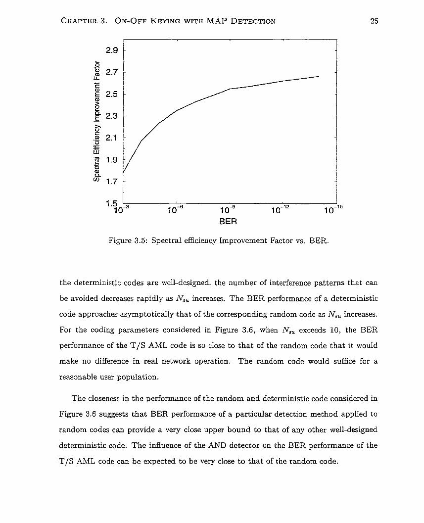
Figure 3.5 shows spectral efficiency improvement factor for different BER require-
ments. The figure shows that for lower BER, the AND detector provides a greater
improvement over the SUM detector for the same dimension. For a BER lower than
the number of users supported by the system using AND detector is at least dou-
ble that using SUM detector. The AND detector thus doubles the spectral efficiency of
the O-CDMA system using OOK.
From [Il], the BER of a deterministic MW-O-CDMA code, the T/S -4ML code,
obtained using the SUM detector is
NSU-1 N s u - 1 4
BER = - 2 ( " u l) (5) (1 - g) i= Nw
where N,, is the number of sirnultaneous users in the system, Lt is temporal length
CHAPTER 3. ON-OFF KEYING WITH MAP DETECTION
20 30 40 50 60 70 Nsu
Figure 3.4: BER performance as a function of the number of active users (N,) for
random codes. Results are obtained using (3.19) and (3.17) for W = 36, D = 1333.
employed, and fVLV is the number of wavelength channels used. For cornparison, the
BER performance of T/S AML code calculated from (3.20) with the same parameters
(iVw = 5, Lt = 23, IV = 5 ) using the SUM detector is shown in Figure 3.6. Again,
simulation and calculation resul'ts agree well.
Since (3.20) takes into account the unity cross-correlation property of the T/S AML
code, its performance is expected to be better than that of the random code. However,
as the number of active users in the system increases, its performance closely approaches
that of the random code. With only a small number of active users in the nettvork,
only a few possible interference patterns will give rise to an error. The deterministic
codes are well-designed to avoid these interference pattern. They perform better than
the random codes when the number of active users in the network is small. As more users
becorne active, more interference patterns can give rise to a detection error. Although
BER
Figure 3.5: Spectral efficiency Improvement Factor vs. BER.
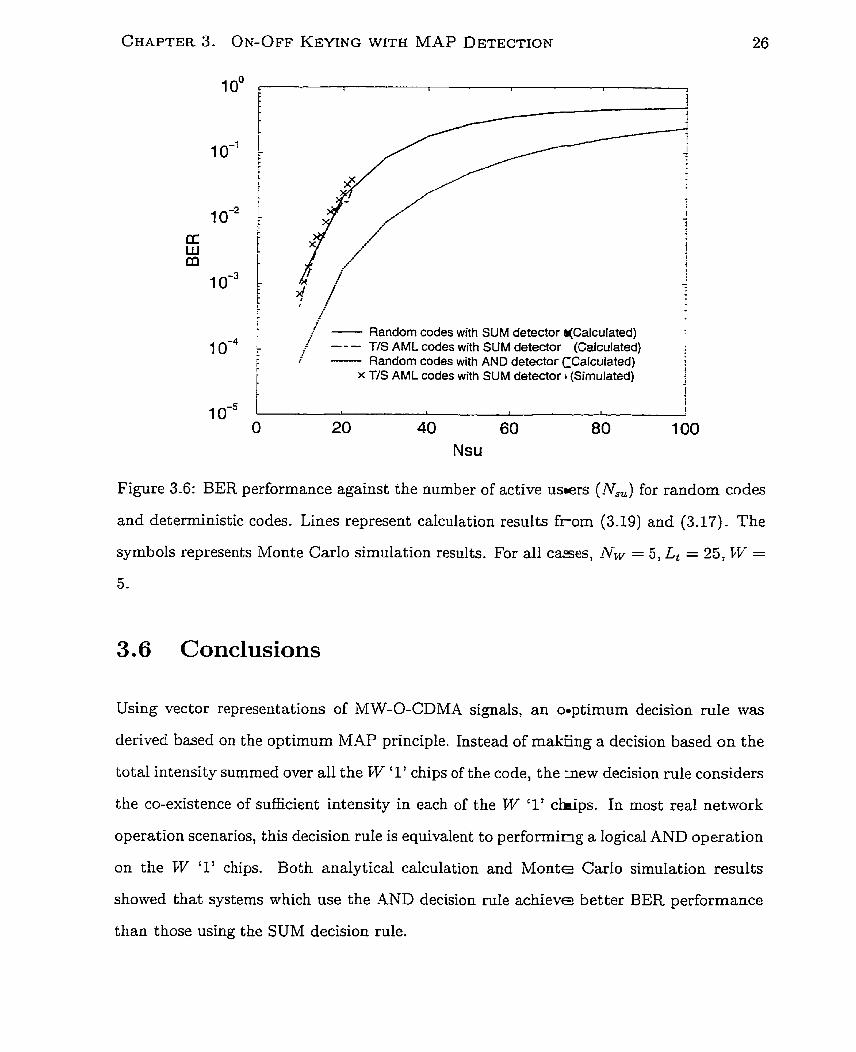
the deterrninistic codes are well-designed, the number of interference patterns that can
be avoided decreases rapidly as rVs, increases. The BER performance of a deterministic
code approaches asymptotically that of the corresponding random code as N,, increases.
For the coding parameters considered in Figure 3.6, when N', exceeds 10, the BER
performance of the T/S AML code is so close to that of the random code that it mould
make no difference in real network operation. The random code would suffice for a
reasonable user population.
The closeness in the performance of the random and deterministic code considered in
Figure 3.6 suggests that BER performance of a particular detection method applied to
random codes can provide a very close upper bound to that of any other well-designed
deterministic code. The influence of the AND detector on the BER performance of the
T/S AML code can be expected to be very close to that of the random code.
r i - Random codes with SUM detector qcalculated) : ---
j T/S AML codes with SUM detector (Calculated) 1
i - Random codes with AND detector CCalculated) : F x T/S AML codes with SUM detector i (Sirnulated) r 1
Nsu
Figure 3.6: BER performance against the number of active usmers (Na) for random codes
and deterministic codes. Lines represent calculation results f rom (3.19) and (3.17). The
syrnbols represents Monte Carlo simulation results. For al1 cases, NFv = 5, Lt = 25, lW =
Conclusions
Using vector representations of MW-O-CDMA signals, an o~ptimum decision rule was
derived based on the optimum MAP principle. Instead of makEng a decision based on the
total intensity summed over al1 the W '1' chips of the code, the _new decision rule considers
the CO-existence of sufficient intensity in each of the W '1' chips. In most real network
operation scenarios, this decision rule is equivalent to performing a logical AND operation
on the VV '1' chips. Both analytical calculation and Monte Carlo simulation results
showed that systems which use the 4 N D decision rule achieve better BER performance
than those using the SUM decision rule.
CHAPTER 3. ON-OFF KEMNG WTH MAP DETECTION 27
It is shown for the fkst t h e in the present work that the AND decision rule always
performs better than the conventional SUM detection rule. This work quantifies, for
the first time, the spectral eEciency improvement gained from this AND decision rule.
In most actual network scenarios, the AND decision rule doubles the spectral efficiency
over the system using SUM detection. This work shows that deterministic codes perform
rnarginally better than random codes with the same dimension. Flexible, high-cardinality
random codes suffice most applications. Random codes provide a tight upper bound for
BER performance of deterministic code systems.
Chapter 4
Bipolar Signaling over the Unipolar
Channel
4.1 Introduction
Unipolar CDMA codes were developed for intensity modulation/direct detection (IM/DD)
optical channels so that simple on-off keying (OOK) may be used. In OOK, however,
the receiver cannot distinguish between a bit "0" and an absence of information since
both are represented by the absence of code. In conventional wireless CDM.4 system, the
use of coherent carrier pemits binary phase-shift keying (BPSK) and thus bipolar codes.
Instead of consisting '1's and 'O's, bipolar codes consist of ' f l ' s and '-lys. m e n BPSK
is used with bipolar codes, bit "1" is represented by the code while bit "0" is represented
by the negative version (a n phase shift of the carrier) of the code. The ambiguity in a b i t
"O" versus an absence of information is rernoved. Excellent cross-correlation properties
enable low BER to be achieved using BPSK.
If bipolar codes could be transferred to the unipolar optical channel, ambigciity could
be avoided and system performance improved. In the present chapter, a scheme is devel-
oped to reproduce the effect of bipolar signaling. It is shown that this allows the effective
use of bipolar codes over the unipolar optical CDMA channel.
4.2 A BPSK CDMA System Using Bipolar Codes
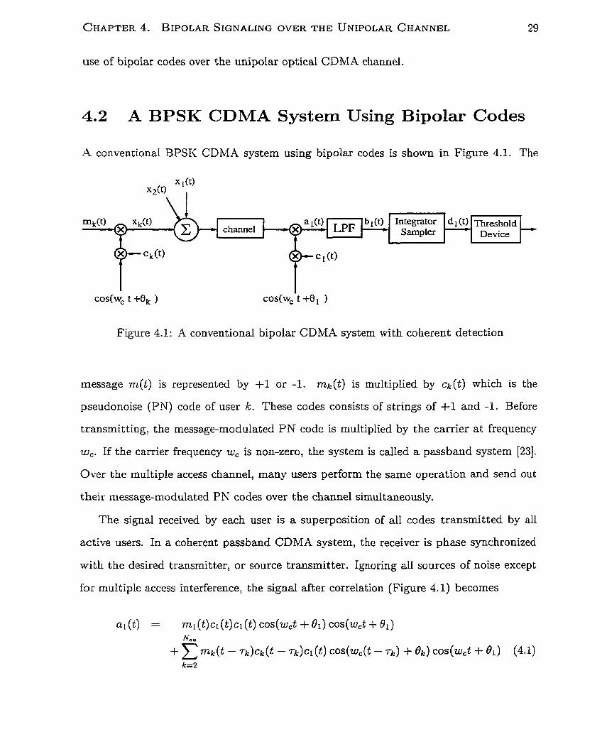
-4 conventional BPSK CDMA system using bipolar codes is shown in Figure 4.1. The
Figure 4.1: A conventional bipolar CDMA system with coherent detection
message m(t) is represented by +l or -1. mk(t) is multiplied by ck(t) which is the
pseudonoise (PN) code of user k. These codes consists of strings of +l and -1. Before
transmitting, the message-modulated P N code is rnultiplied by the carrier at frequency
w,. If the carrier frequency w, is non-zero, the system is called a passband system [23].
Over the multiple access channel, many users perform the same operation and send out
their message-modulated PN codes over the channel simultaneously.
The signal received by each user is a superposition of al1 codes transmitted by al1
active users. In a coherent passband CDMA system, the receiver is phase synchronized
with the desired transmitter, or source transmitter. Ignoring al1 sources of noise except
for multiple access interference, the signal after correlation (Figure 4.1) becomes
where r k is the time shift between the target code cl (t) and the code of user k. The first
term in (4.1) is the correlated signal from the source transmitter. The second term is
the correlated signal for the messages sent by other transmitters: it represents the MAI
component of the received signal. After the low pass filter (LPF),
In the second term, since the phase of other transmitters is not generally the same as
that of source transmitter, the factor of cos(Bk - wCrk - 81) attenuates the interference
caused by user k. After integrating the signal over a bit period and sampling it at the
end of the period, the signal becomes
The absolute value of the first term in (4.3) is E6, the energy per bit. This is a deter-
ministic quantity: the in-phase autocorrelation of bipolar codes is unity and the energy
carried by each bit sent is E6- The second term, which embodies al1 MAI, is random
since the cross-correlation and phase difference between pairs of codes are unequal.
If the cross-correlation between the bipolar codes is low, the variance of the random
variable is bounded from below by
where Lt denotes the temporal length of the code [24]. The signal to interference ratio
(SIR) is thus upper bounded [25] by
SIR = Nsu -' E6
3Lt
The correlator receiver is an MAP detector when al1 signal degradation effects have
Gaussian distributions [21].
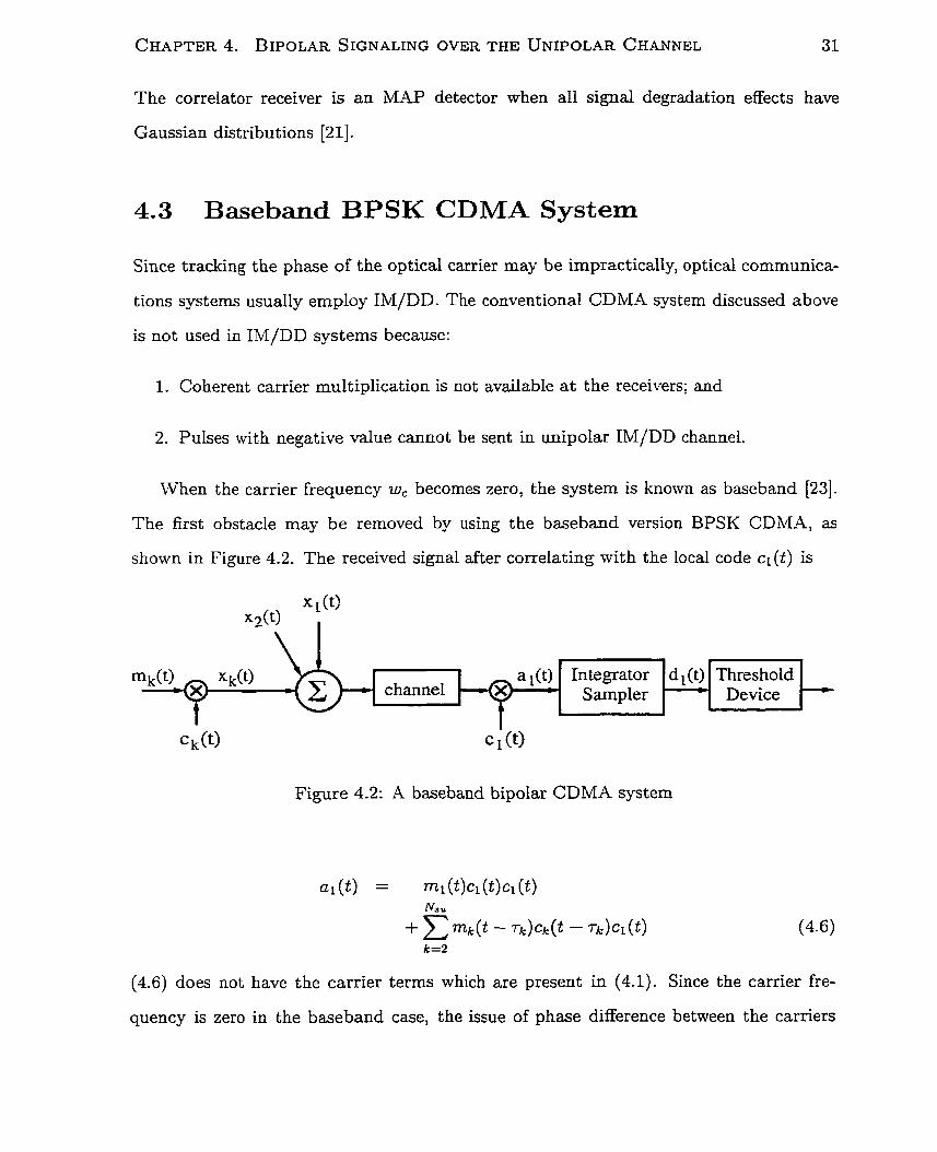
4.3 Baseband BPSK CDMA System
Since tracking the phase of the optical carrier may be impractically, optical communica-
tions systems usually employ IM/DD. The conventional CDMA system discussed above
is not used in IM/DD systems because:
1. Coherent carrier multiplication is not available a t the receivers; and
2. Pulses with negative value c a n o t be sent in unipolar IM/DD channel.
When the carrier frequency w, becomes zero, the system is known as baseband [23].
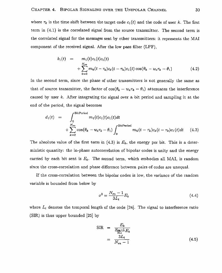
The first obstacle may be removed by using the baseband version BPSK CDMA, as
shown in Figure 4.2. The received signal after correlating with the local code cl (t) is
Figure 4.2: A baseband bipolar CDMA system
(4.6) does not have the carrier terms which are present in (4.1). Since the carrier fre-
- d (t) channel
quency is zero in the baseband case, the issue of phase difference between the carriers
Threshold Device
i A
CHAPTER 4. BIPOLAR SIGNALING OVER THE UNIPOLAR CHANNEL 32
vanishes. The absence of phase difference eliminates its attenuation effect on signals sent
by interfering transmitters. The effect of MAI in the baseband system is stronger than
that in the coherent passband system. After the integrator sampler,
As in the passband case, the first term is Ebr the energy per bit. The variance of BI-41,
the second term in (4.7), is bounded from below [19] by
The difference between (4.8) and (4.4) shows that the absence of the carrier terms in
the baseband case doubles the variance of MAI. The SIR for the baseband case is upper
bounded by
Comparison between (4.9) and (4.5) shows that to achieve the same SIR with the same
code length, the baseband system can only allow half as many active users as the coherent
passband system.
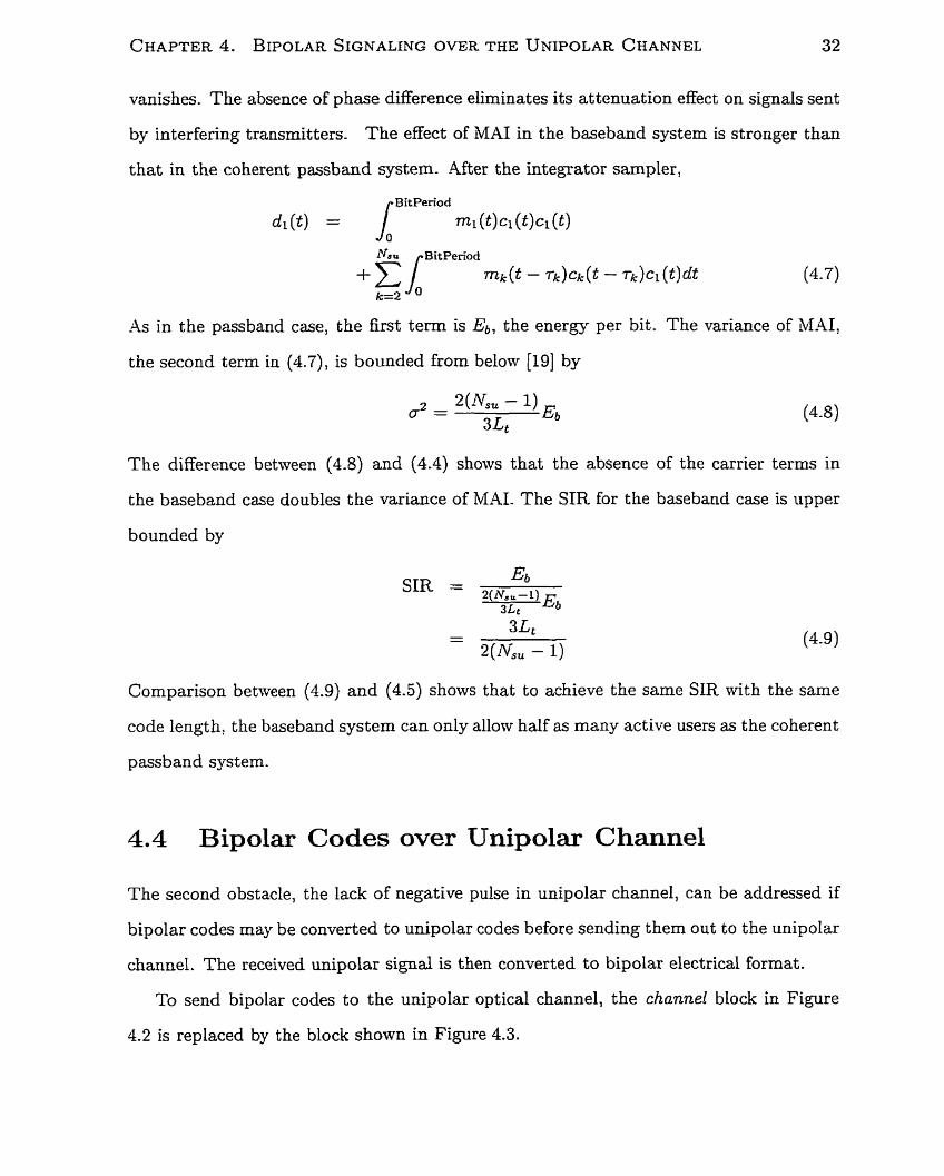
4.4 Bipolar Codes over Unipolar Channel
The second obstacle, the lack of negative pulse in unipolar channel, can be addressed if
bipolar codes may be converted to unipolar codes before sending them out to the unipolar
channel. The received unipolar signal is then converted to bipolar electrical format.
To send bipolar codes to the unipolar optical channel, the channel block in Figure
4.2 is replaced by the block shown in Figure 4.3.
CHAPTER 4. BIPOLAR SIGNALING OVER THE UNIPOLAR CHANNEL 33
Figure 4.3: The enabling block for sending bipolar codes over the unipolar channel. xk ( t )
is the electrical bipolar data signal; y k ( t ) is the optical unipolar data signal; zl ( t ) is the
optical unipolar received signal and ~ ( t ) is the electrical bipolar received signal.
xk(0 -
At the input,
Through electro-optic conversion, '+1' and '-1' of the bipolar code are converted to '1'
and 'O' of the unipolar code. The conversion function is given by
a At)
channel
These unipolar codes are then sent from al1 the active users along the fibre. At the
receiver, the unipolar signal is
o/e H processin+- z l(t> 3 e/o ] t
fibre A
After the optical pulses are converted to electrical form, the signal processor converts the
signal back to bipolar form. If the conversion function is
then, the bipolar format of the received signal is
The signal in (4.13) is identical to the signal in (4.6) before correlation. The receiver
structure in Figure 4.3 can then be used to process the bipolar signal.
Replacing the channel bIock in the baseband CDMA system by the block shown in
Figure 4.3 enables the transmission of bipolar codes using the unipolar optical channel.
For the transmitter before the x t ( t ) point and the receiver before the al ( t ) point, the
channel is essentially a bipolar channel. Transmitter and receiver structures developed
for BPSK CDMA systems using bipolar codes may then be used in this optical system,
wit h signal processing carried out electronically. Only the transmission portion of the
system is optical. This system is referred to as the electro-optic/opto-electrmic (EOE)
system throughout this work.
Signal processing requires scaling of the signal and performing offset on whose value
depends on the number of active users in the system. This may be inferred from the light
intensity on the channel.
4.5 Performance Cornparison
The signals at the transmitter end ( x k ( t ) ) and the receiver end (al ( t ) ) of the EOE system
are identical to those of the baseband system. Signal processing for detection and decision
making are identical in the two systems. Thus, the SIR of the EOE system is identical
to that of the baseband one (4.9).
For a BPSK CDMA system using bipolar codes, if the number of active users in the
system is large enough, the effect of MAI may be approximated by a zero mean Gaussian
random variable. The bit error rate rnay then be calculated using the Q-function
BER = Q(JsIR)
The bit error rate for the coherent passband system is therefore
while that for baseband/EOE system is
Figure 4.4 shows Monte Carlo simulated BER of the EOE systems for a random code
and a Gold sequence. The theoretical BER calculated for coherent passband (4.16) and
baseband (4.17) bipolar CDMA systems are also shown for cornparison.
Figure 4.4 shows that the simulation data for the EOE system using Gold sequence
agree well with the Gaussian approximation of the baseband system. As the number of
active users increases, the BER values calculated agree more closely with those obtained
from the simulation. This reinforces that the Gaussian approximation for MAI is o d y
good for very large number of active users. It provides a lower bound when there are few
active users.
The figure also shows that the EOE system using a random code performs much worse
than that using Gold sequence. Since the two codes in BPSK are 2's complements of
each other, their densities (ratio of code weight to code length) are about one half. Since
bipolar codes are much more dense than unipolar codes, achieving good BER performance
reIies on very low cross-correlations between the codes. Low cross-correlations allow the
receiver to spread the interfering codes by a large factor (of the order of code length).
Interference is reduced and good BER can be achieved. Random codes, which do not
l / / - .'
.'
i / / !
I ,/ O Gold sequence (Simulated) 1 r /--- Coherent passband systern (Calculated) f i II- Baseband system (Calculated) I I
i o Random code (Simulated) j
O 20 40 60 80 100 Nsu
Figure 4.4: BER as a function of 4, for baseband and coherent passband bipolar CDMA
systems. Lines represent calculation results from (4.17) and (4.16). Syrnbols indicate data
points from Monte Carlo simulation of the EOE system. For al1 cases, Lt = 127.
have this low cross-correlation property, perform much worse than well-designed bipolar
codes such as Gold codes-
The spectral efficiency of the EOE system is half that of the coherent passband
system, regardless of the system BER. Figure 4.5 compares the spectral efficiency of
coherent system with tha t of the proposed system for a range of required system BER.
These efficiencies represent upper bounds since the Gaussian approximations for bit error
rate calculations are lower bound estimates. Figure 4.5 shows that the coherent passband
system can always achieve twice the spectral efficiency of the baseband system.
4.6 Conclusions
In this chapter, the transmission of bipolar codes over the unipolar channel was treated
through development of a fully general formalism.
1 i
--- Coherent passband system 1 /
Baseband system
j , 6 1 0-l4 1 0-l2 1 0 - ' O 1 1
BER
Figure 4.5: Spectral efficiency as a function of BER ceiling for coherent passband system
and the EOE system.
By dewloping a simple linear unipolar-to-bipolar operation and its inverse, the direct
correspondence in MAI performance with baseband bipolar CDMA was shown.
Because MAP receivers are known for coherent and incoherent wireless bipolar CDMA,
analysis of these systems provides fundamental best-case cornparison for O-CDMA sys-
tem performance. In the chapter which follows, the formalisms and discoveries of Chapter
3 and Chapter 4 will be integrated to evaluate the fundamental performance possibilities
of O-CDMA compared with achieved values.
Chapter 5
Discussion and Generalizat ion
5.1 Introduction
If an O-CDMA system could employ very complicated hardware to perform the most com-
plicated data processing, al1 methods developed for conventional bipolar CDMA syst ems
could be applied to O-CDMA. For instance, coherent systems proposed in [26, 27, 28, 291
encode data in the phase of the carrier.
More modestly, the system proposed in [4] employs complicated electronics to process
signais at the receiver. Optical AND gates are suggested in [30] to facilitate all-optical
code recognition- Through complicated data processing, O-CDMA systems may achieve
improved spectral efficiency. However, the cost of applying such cornplicated signal pro-
cessing may be very high since, at present, optical phase tracking and nonlinear optical
signal processing are exotic and costly methods.
At the other extreme, an optical CDMA system may employ the simplest and most
econornical devices to process data. Systems proposed in [14, 11, 21 are examples of this
kind. Each uses non-tunable optical tapped delay lines to perforrn decoding. Although
system cost can be reduced, the spectral efficiency achieved is relatively low; less data
processing extracts less information from the received signal.
CHAPTER 5 . D~SCUSSION AND GENERALIZATION 39
This situation presents an immediate challenge to understand the qualitative and
quantitative nature of the compromise between the two extremes. On one hand, the
economical systems may be able to afford more data processing if, for minimal effort,
there is a substantial improvement in spectral eficiency performance. On the other hand,
the most costly systems may be able to give up the most complicated data processing if
systems may thereby be made more affordable with only a minor reduction in spectral
efficiency.
It is necessary to explore and compare the spectral efficiency performance of IM/DD
O-CDMA systems, inchding those newly developed and the present work:
0 OOK system using conventional SUM detection;
0 OQK system using the optimum AND detection; and
EOE system proposed in Chapter 4.
The feasibility of implementing these systems will then be investigated by exploring and
comparing hardware requirements.
5 -2 BER Performance and Spectral Efficiency
The simplest and most econornical O-CDMA systerns would employ OOK as moduIation
scheme and total energy summation as detection method [IO, 11, 121. The other ext~iine
would be the coherent passband system discussed in the previous chapter.
Figure 5.1 compares the bit error rate performance of these O-CDMA systems. The
OOK system with SUM detector, as discussed in Chapter 3, was designed to minimize
hardware complexity. The figure shows calculation values from (3.19). On the O t her hand,
the coherent passband system is aimed at minimizing error probability through intensive
processing. The figure shows Gaussian approximated calculation values from (4.16). The
Figure shows a significant BER performance gap between the coherent passband system
CHAPTER 5 . DISCUSSION AND GENERALIZATION
Coherent passband system ---- OOK systern with SUM detector
Nsu
Figure 5.1: BER for different Ku. The dimension for OOK system using SUM detection
is 125. The code length for coherent paçsband system is 127. Both of them are calculation
values.
and the OOK CDMA with SUM detection. While it was shown in Chapter 3 that the
AND detector performs better than the SUM detector in OOK system, it was shown in
Chapter 4 that the proposed EOE system can still achieve a reasonable BER by giving up
some of the most complicated data processing functionality. It is important to understand
where these systems lie in the BER gap of Figure 5.1.
Figure 5.2 shows the BER performance of the OOK system with AND detector and
the EOE system. For comparison, the Gaussian approximated calculation values for
baseband and coherent passband systems are also shown.
This figure shows that the AND detector, derived from the optimum MAP decision
rule, brings the BER performance of the system using unipolar codes close to that of
bipolar baseband system. The extra data processing required by the AND detector
extracts more information from the received signal and improves the BER performance
CHAPTER 5. DISCUSSION AND GENERALIZATION
&OK with SUM detector (Sirnulated) i / Coherent pwband systern (Calculated) 1
1 x OOK with AND detector (Simulated) X I O The EOE systern (~imulated) i , --- O : Baseband system (Calculated) I
I !
I -
O 20 40 60 80 100 Nsu
Figure 5.2: BER for different IV,,. The OOK systems employs unipolar codes with a
code dimension of 135. The other systems use Gold sequences with code length of 127.
of the system. Using the rnatched filters, the performance of EOE system also approaches
very closely that of the bipolar baseband system. In an effort to mimic the effect of a
bipolar baseband CDMA system, the EOE system utilizes, as much as possible, the
existing optimal transmitter and receiver structures for bipolar systems. It only gîves
up the most complicated function-phase tracking in the receiver. Although t hese two
systems employ different design philosophies, Figure 5.2 shows that their performances
are nearly overlapping. The performance of each system approaches that of the bipolar
baseband system very closely.
Since the calculated BER values for the baseband system in Figure 5.2 are Gaussian
approximated lower bound, they serve as the lower bound for the optimal bipolar base-
band CDMA system. It may be shown [23] that an optical IM/DD systern is operationally
equivalent to a bipolar baseband system. Hence, the proximity of the performances of
these two systems to that of the bipolar baseband system implies that the AND detector
and the EOE system closely approach the best possible single-user detection capacity of
an inco herent multiple access system.
From BER cornparison between the systems, spectral efficiencies may also be com-
pared. Figure 5.3 shows the upper bound spectral efficiencies for the baseband system,
the coherent passband system, and the unipolar OOK system using SUM operation.
1 OOK system with SUM detector 0110' 1
/ ----- Coherent passband system / /
/ 1
/ ----- Baseband system F fl ! / - ./ I
I 1 1 0-l4 10'" 1 0 - ' O 1 o - ~ 1 oe6
BER
Figure 5.3: Spectral efficiency for different BER.
As BER requirements become more stringent, the spectral efficiency of the system
decreases-a fundamental characteristic of a code-division multiple access system. The
figure shows that the unipolar OOK system using SUM detection can only achieve half
the spectral efficiency of that for the baseband system. The baseband system, as shown in
Figure 4.5, can only achieve half the spectral efficiency of that for the coherent passband
system. Since Figure 5.2 shows that the BER performance of the unipolar system with
AND detection and the EOE system are very close to the lower bound given by the
baseband system, the spectral efficiency for the baseband system shown in Figure 5.3
represents the performance of the above two systems. In sum, optimum receivers can
then bring the spectral efficiencies of the optical direct-detection systems up to tthe bipolar
baseband level. For a BER of IO-^, the MAP receiver brings the spectral ernciency up
from less than 2% to almost 5%. Further irnprovement from the baseband sys-:tem to the
coherent passband system would rely on the use of coherent detection techniques.
It is worthwhile to compare the hardware implementation of the two systems with
similar performance to find out which one c m be more readily implemented.
5.3 Hardware Implementat ion
The generalized single-wavelength version of systems discussed is s h o m in Figure 5.4.
At the transmitting end, each active user sends intensity-modulated iight ontbo the fibre
Figure 5 -4: A general single-wavelengt h
User 3 User 2
User 1
optical CDMA network structrrire.
channel. The electrical signal into the modulator provides the destination CDMA code
modulated by the information signal to be sent. At the receiving end, each usser detects
and processes the received signal to estirnate what was sent. It is the functiionality of
the receivers t hat distinguishes the hardware structures of these optical CDM-M systems.
Receiver designs are therefore discussed and compared.
Light Source
In a snapshot, cornparison between the two systems are summarized in Table 5.1.
The detail of each item is explained in the foliowing sub-sections.
Receiver I
- Decision -- Modulator Fibre -
CHAPTER 5 - DISCUSSION AND GENEFULIZATION
System OOK with AND
I
Table 5-1:
Code switching flexibility Flexible for unipolar codes
EOE
Hardware 1 Wavelength
Flexible for bipolar codes
complexity AU-optical:
expandability Expandable
fast, expensive ,411-elec tronic:
slower , 1 by independent
by 2-D codes
less expensive All-electronic only:
less expensive
Expandable
wavelengt h channels
1
Hardware implementation cornparison
Support from higher Iayers Requires protocols to dis t inguis h bit "O" and silence Receiver dis tinguishes bit "0:' and silence directlv
5.3.1 Structure
OOK system with AND detection
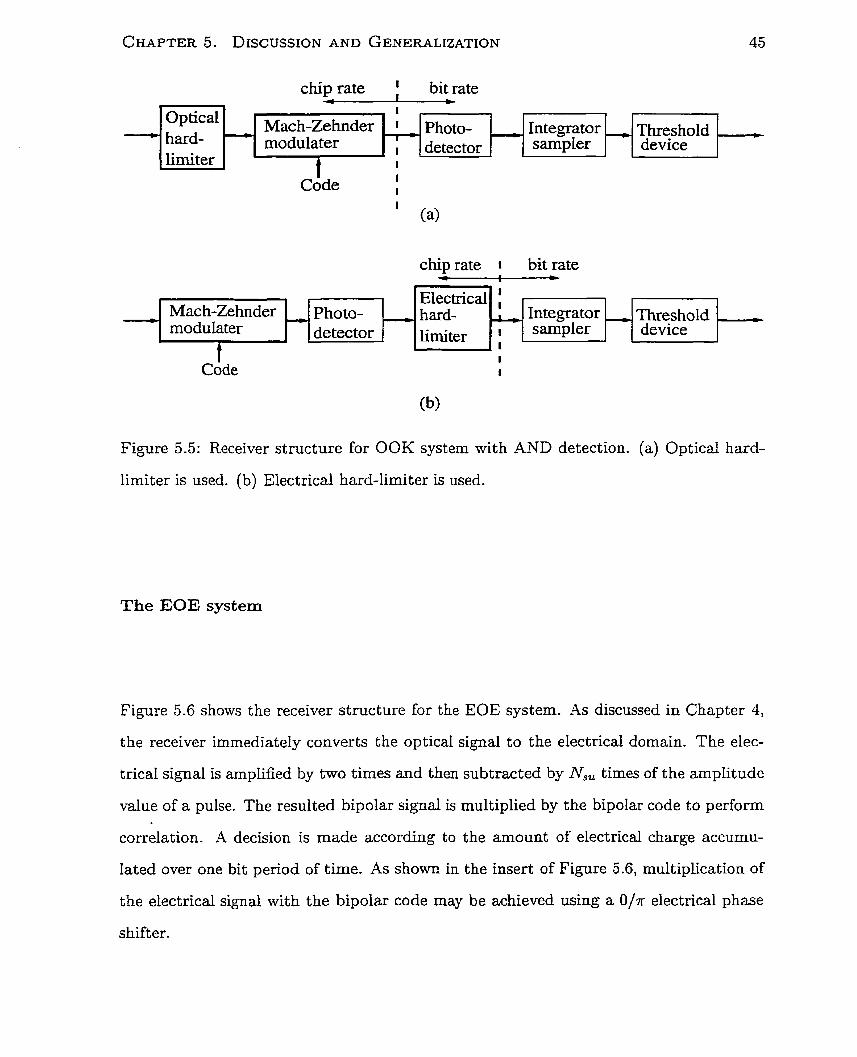
Figure 5.5 shows two receiver designs for a single-wavelength OOK system using unipolar
codes and ,AND detection- In this case, the unipolar code is a one-dimensional code which
uses only the time axis for coding. -4s shown in Chapter 3, hard-limiters may enable AND
detection. Figure 5.5a shows the optical hard-limiter version. The optical hard-limiter
clamps the received optical signal to the intensity level of an optical pulse sent at the
transmitting end. The Mach-Zehnder modulator (MZ) acts as a gate which opens and
closes according to the code assigned to this receiver. After photodetection, the integrator
sampler sums the total photocurrent received over one bit period of time. The threshold
device decides that a bit "1" was sent only when the accumulated photocurrent exceeds
the threshold which is equal to the code weight.
Although nonlinear periodic devices are promising candidates for implementing opti-
cal hard-limiting, these have yet to be realized. Electrical hard-limiters are widely avail-
able. The electrical hard-limiter version is shown in Figîre 5.5b. When the electrical
hard-limiter is used instead of optical hard-limiter, the hard-limiter must be positioned
after the photodetector, but before the integrator sampler.
chip rate ' bit rate - *
Figure 5.5: Receiver structure for OOK system with AND detection. (a) Optical hard-
chip rate 1 bit rate e . . w
limiter is used. (b) Electrical hard-limiter is used.
t I
Code I I
Op tical hard- limiter
The EOE system
Figure 5.6 shows the receiver structure for the EOE systern. As discussed in Chapter 4,
I
t I Code I
Electrical bard- limiter
: Mac h-Zehnder photo- detector
the receiver immediately converts the optical signal to the electrical domain. The elec-
,
trical signal is amplified by two times and then subtracted by N,, times of the amplitude
-
-
value of a pulse. The resulted bipolar signal is multiplied by the bipolar code to perform
correlation. A decision is made according to the amount of electrical charge accumu-
Mach-Zehnder modulater
Threshold htegrator
Iated over one bit period of time. As shown in the insert of Figure 5.6, multiplication of
- I
1
- sampler r
the electrical signal with the bipolar code may be achieved using a O / K electrical phase
,
device
shift er.
photo- detector
Threshold device
- . btegrator sampler
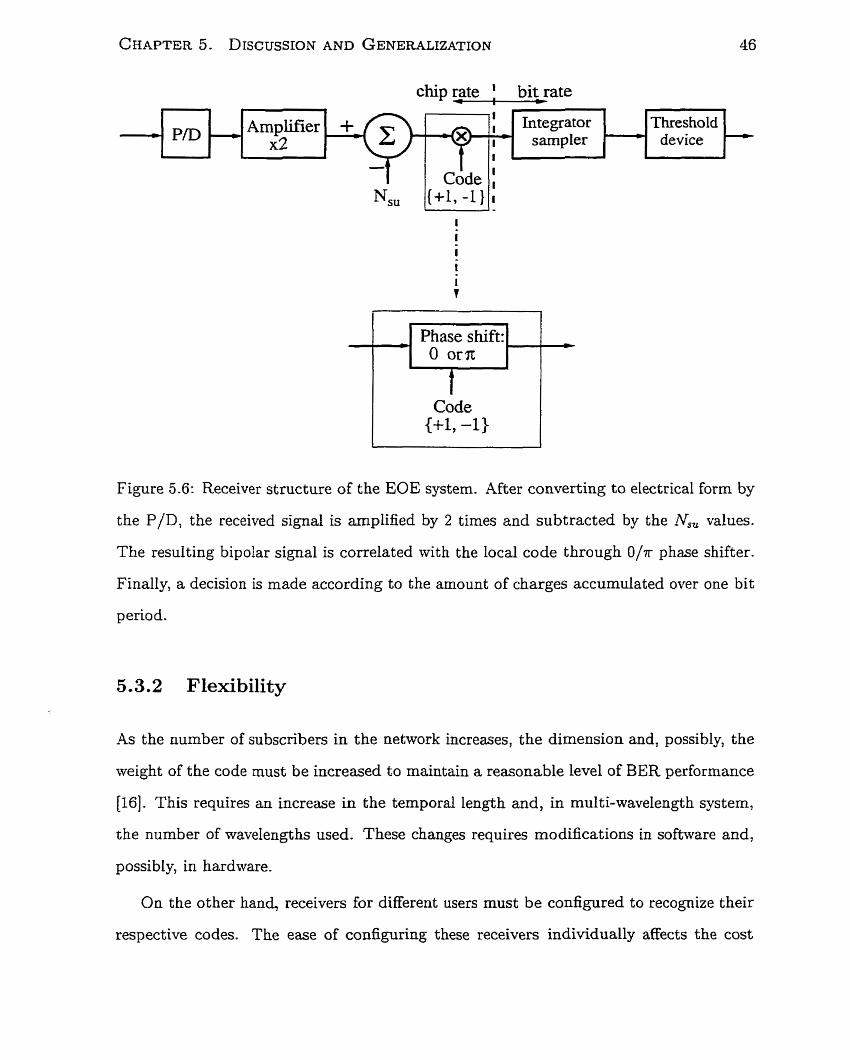
Phase shift: 1-j O orn t-+--
Figure 5.6: Receiver structure of the EOE system. After converting to electrical form by
the P/D, the received signal is arnplified by 2 times and subtracted by the N,, values.
The resulting bipolar signal is correlated with the local code through O/T phase shifter.
Finally, a decision is made according to the amount of charges accumulated over one bit
period.
-
5.3.2 Flexibility
Threshold device
-4s the number of subscribers in the network increases, the dimension and, possibly, the
weight of the code must be increased to maintain a reasonable level of BER performance
[16]. This requires an increase in the temporal length and, in multi-wavelength system,
the number of wavelengths used. These changes requires modifications in software and,
possibly, in hardware.
1 +- ' Integratm sampler '
-
On the other hand, receivers for different users must be configured to recognize their
respective codes. The ease of configuring these receivers individually affects the cost
I
* - P D Amplifier x2
and, hence, the feasibility of deployment of such system. It is worthwhile to study the
flexïbility of these hardware structure io decoding different codes.
OOK system with AND detection
Only the operation of the MZ, the integrator sampler, and the threshold device depend
on the code dimension and weight. Although the state of the MZ is controlled by the
code, the modulating signal is electrical and controlled by receiver software. Similady,
although the threshold of the threshold device is set to the code weight, this device is
all-electronic in its operation. The threshold is readily adjusted. This receiver structure
requires only a software change to shift to other codes.
The EOE system
Data processing in this receiver structure is carried out using electronics. As long as the
electronics is designed to be reconfigurable by end users, any bipolar codes can be used
in this system. It is fully compatible with any bipolar CDMA system so that any bipolar
codes can be used.
5.3.3 Hardware Speed and Complexity
The MZ, photodetector, integrator sampler and t hreshold device are common components
to the receiver structures considered. Since the MZs are driven by the code of the receiver,
they need to respond to the controlling signal a t the chip rate. The integrator sampler
accumulates electrical charge over a period of time and can operate a t the bit rate. The
threshold device determines the amount of charge accumulated at the end of every bit
period and may respond at the bit rate. The following subsections describe the particular
components required for each individual receiver structure.
CHAPTER 5 . DISCUSSION AND GENERALIZATION
OOK system with AND detection
The hard-limiter is essential in the AND operation. If an optical hard-limiter is to
be used, continuous control is not required since this is a purely passive device. If an
electrical hard-limiter is used instead, the electronics involved will be required t O operate
a t the chip rate.
The EOE system
The major added component required in this structure is the unipolar-bipolar conver-
sion device. This simple electronic device requires accurate knowledge of the number of
active users. A major advantage of this system is that existing bipolar baseband CDMA
receivers may be used. The electronics must operate at the chip rate.
5.3.4 Wavelength expandability
The preceding analysis assumes that only a single wavelength channel is used in the
system. In fact, the two systems mentioned above can be expanded to use multiple
wavelength channels, allowing an increase in the bit rate of the system without increasing
the temporal chip rate.
In a single-wavelength system, each bit period consists of a complete string of the
code, so that
Chip rate Bit rate =
Lt
where Lt is the temporal length of the code. This is valid regardless of the kind of code
used. The above systems may be made multi-wavelength by repeating the same operation
independently for a vumber of wavelengths. Since data are sent in parallel and processed
independently at each wavelength channel, the capacity of the system is scaled up by the
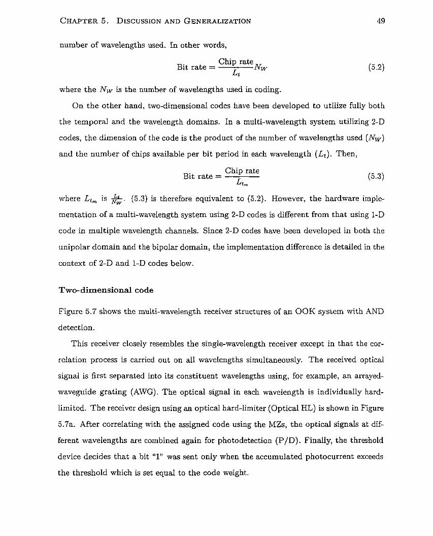
number of wavelengths used. In other words,
Chip rate Bit rate =
Lt Nw
where the NCv is the number of wavelengths used in coding.
On the other band, two-dimensional codes have been developed to utilize fully both
the temporal and the wavelength domains. In a multi-wavelength system utilizing 3-D
codes, the dimension of the code is the product of the number of wavelengths used (Nw)
and the number of chips available per bit period in each wavelength (Lt ) . Then,
Chip rate Bit rate =
L tm
where Lt, is &- (5.3) is therefore equivalent to (5.2). However, the hardware imple-
mentation of a multi-wavelength system using 2-D codes is different from that using 1-D
code in multiple wavelength channels. Since 2-D codes have been developed in both the
unipolar domain and the bipolar domain, the implementation difference is detailed in the
context of 2-D and 1-D codes below.
Two-dimensional code
Figure 5.7 shows the multi-wavelength receiver structures of an OOK system with AND
detection.
This receiver closely resembles the single-wavelength receiver except in that the cor-
relation process is carried out on al1 wavelengths simultaneously. The received optical
signal is first separated into its constituent wavelengths using, for example, an arrayed-
maveguide grating (AWG). The optical signal in each wavelength is individually hard-
limited. The receiver design using an optical hard-limiter (Optical HL) is shown in Figure
5.7a. After correlating with the assigned code using the MZs, the optical signals at dif-
ferent wavelengths are combined again for photodetection (P/D) . Finally, the t hreshold
device decides that a bit "1" was sent only when the accumulated photocurrent exceeds
the threshold which is set equal to the code weight.
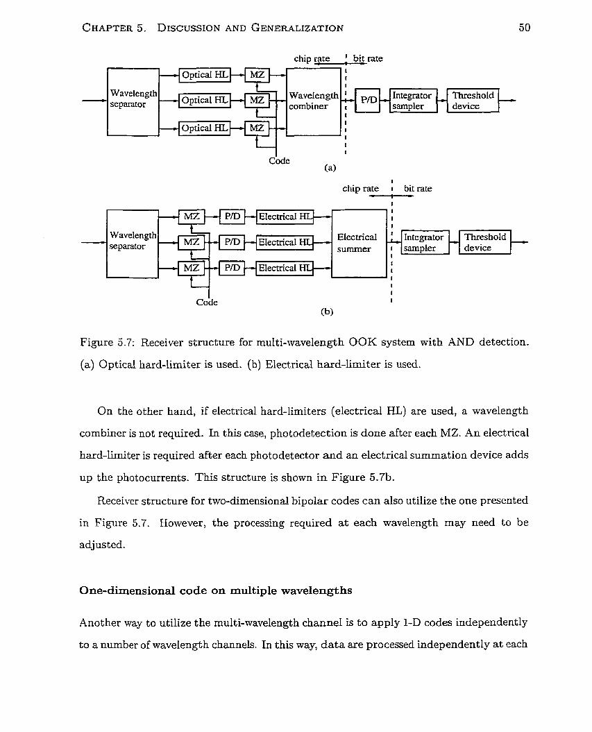
CHAPTER 5. DZSCUSSION AND GENERALIZATION
1
chip rate I bit rate -1-
chip rate ! bit rate I 1 1
Figure 5.7: Receiver structure for multi-wavelength OOK system with AND detection.
(a) Optical hard-limiter is used. (b) Electrical hard-limiter is used.
- Wavelength se parator combiner I sarnpler
>
On the other hand, if electrical hard-Iimiters (electrical HL) are used, a wavelength
combiner is not required. In this case, photodetection is done after each MZ. ,4n electrical
hard-limiter is required after each photodetector and an electrical summation device adds
up the photocurrents. This structure is shown in Figure 5.7b.
Receiver structure for two-dimensional bipolar codes can also utilize the one presented
in Figure 5.7. However, the processing required at each wavelength may need to be
adjusted.
1 I t I 1 I
Code (a>
Threshold device
One-dimensional code on multiple wavelengths
1 I
I
Code I
(b)
1 1 I
Another way to utilize the multi-wavelength channel is t o apply l-D codes independently
to a number of wavelength channels. In this way, data are processed independently at each
Wavelength Electrîcal separator summer 1
I *
Electricai 1 I '
- - Threshold device
Integrator sampler
-
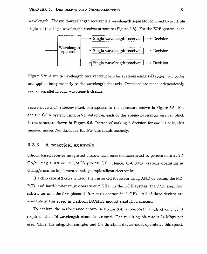
wavelength. The multi-wavelength receiver is a wavelength separator followed by multiple
copies of the single-wavelength receiver structure (Figure 5.8). For the EOE system, each
- Decision
Wavelength separator Decision
= Decision
Figure 5 -8: A multi-wavelength receiver structure for systems using 1-D codes. 1-D codes
are applied independently to the wavelength channels. Decisions are made independently
and in parallel in each wavelength channel.
single-wavelength receiver block corresponds to the structure shown in Figure 5.6. For
the the OOK system using AND detection, each of the single-wavelength receiver block
is the structure shown in Figure 5.5. Instead of making a decision for one bit only, this
receiver makes IVw decisions for N L ~ bits simultaneously.
5.3.5 A practicd exarnple
Silicon-based receiver integrated circuits have been demonstrated to process data at 2.5
Gb/s using a 0.8 pm BiCMOS process [31]. Hence, O-CDMA systems operating a t
Gchip/s can be implemented using simple silicon electronics.
If a chip rate of 2 GHz is used, then in an OOK system using AND detection, the MZ,
P/D, and hard-limiter must operate a t 2 GHz. In the EOE system, the P/D, amplifier,
subtracter and the O/K phase shifter must operate in 2 GHz. Al1 of these devices are
available a t this speed in a silicon-BiCMOS modest resolution process.
To achieve the performance shown in Figure 3.4, a temporal length of only 83 is
required when 16 wavelength channels are used. The resulting bit rate is 24 Mbps per
user. Thus, the integrator sampler and the threshold device must operate at this speed.
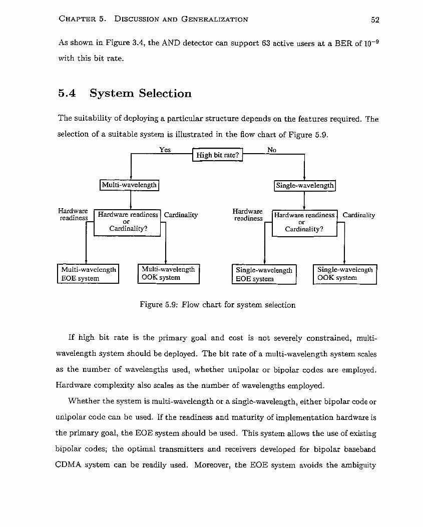
As shown in Figure 3.4, the AND detector can support 63 active users a t a BER of 10-~
tvith this bit rate.
System Selection
The suitability of deploying a particular structure depends on the features required. The
selection of a suitable system is illustrated in the flow chart of Figure 5.9.
Multi-w avelength -7
Figure 5.9: Flow chart for system selection
Hardware readiness Harduare!eadiness Cardinaiity Hardware Hardware!readiness Cardinaiity
If high bit rate is the primary goal and cost is not severely constrained, muiti-
wavelength systern should be deployed. The bit rate of a multi-wavelength system scales
as the number of wavelengths used, whether unipolar or bipolar codes are employed.
Hardware complexity also scales as the nurnber of wavelengths employed.
Whether the system is rnulti-wavelength or a single-wavelength, either bipolar code or
unipolar code can be used. If the readiness and maturity of implernentation hardware is
the primary goal, the EOE system should be used. This system allows the use of existing
bipolar codes; the optimal transmitters and receivers developed for bipolar baseband
CDMA system can be readily used. Moreover, the EOE system avoids the ambiguity
or Cardinality?
7 - readiness
+ T T ?
or Cardinali ty ?
P
Multi-wavelength EOE system
Multi-wavelength OOK system
b
Single-wavelength EOE system
Single-wavelength OOK system
CHAPTER 5. DISCUSSION AND GENERALIZATION 53
in a bit "O" versus an absence of information during detection. In contrast, if high
cardinality (maximum size of the set of codes that obeys the constraints) is the primary
goal, the 00 K system with AND detection should be used. In addition to any weI1-
designed unipolar codes, random codes can also be used in this system since it reIies on
the sparsity O-f the codes to achieve low BER performance. Although bipolar codes have
good cardinality, these may not be sufficient to accommodate a very large number of
network subscribers. A set of Gold codes with temporal length Lt can admit only Lt + 2
subscribers in the network. In contrast, random codes have very large cardulality so that
new subscribers to the network can always be accepted.
5.5 Comclusions
It was shown I n the preceding chapters that the unipolar OOK system using AND detec-
tion and the E O E system proposed in Chapter 4 utilize optimum receivers. It was shown
in this chapter for the first time that these two systems exhibit nearly identical BER
performance z n d that this performance approaches very closely that of bipolar baseband
CDMA systern. The proxirnity in performance of the above two systems, taken together
with knowledge of the fundamental performance bound for the bipolar baseband sys-
tem, indicates t hat the systems achieve the maximum spectral efficiency of an incoherent
optical systenr which uses single-user detection.
This chap t e r compared the two systems with respect to hardware implementation.
Multi-wavelensh system should be used if high bit rate is the primary goal. The EOE
system should be used when readily available hardware is the most desired feature. The
OOK system wi th AND detection system using random codes should be used if maximum
cardinality is ~equired.
Chapter 6
Conclusions
6.1 Summary of Work
The explosive growth of the Internet demands innovation of the next generation local
area networks which are economical and support many users a t high bit rates. Optical
fibres provide enormous bandaidth required and code-division multiple access offers the
flexibility needed in the bursty LAN environment.
The esisting O-CDMA systems reviemed in Chapter 1 were largely based on heuristics.
They achieve very lom bit error rate at the price of using very sparse codes and achieving
low spectral efficiency. O-CDMA systems were developed without the knowledge of the
ultimate limits on further performance improvements.
The analytical framework laid out in Chapter 2 provided the foundation for funda-
mental analysis of O-CDMA systems. It enabled performance and efficiency of various
systems to be compared on a fair basis. The Monte Car10 simulation tool introduced in
this chapter enabled imitation of LAN traffic patterns and accurate estimate of system
performance.
O-CDMA systems using unipolar codes were re-examined in Chapter 3 from a fun-
damental communication theoretic perspective. An optimum decision rule was derived
for such systems based on the MAP principle which minimizes the error probability of a
system. Use of this optimum deciaion rule was shown to double the spectral efficiency of
O-CDMA system using unipolar code while maintaining the same bit error rate.
-4 new way of applying existing bipolar codes over the unipolar optical channel was
proposed in Chapter 4. It was shown that the extensively designed and studied codes
designed for the wireiess bipolar channel may be transferred to the unipolar optical chan-
ne1 without compromising the cross-correlation pro~er ty of the codes. Since the optimal
receiver infrastructure for the bipolar channel may then be re-used, the performance of
the resulting EOE system was shown to be identical to that of a baseband bipolar system.
Optimum O-CDMA systems using unipolar codes and bipolar codes were compared in
Chapter 5. Through added data processing, the use of an optimum decision rule brought
the spectral eEciency of the system using unipolar codes close to the upper bound for
incoherent bipolar CDMA system. By giving up only the phase tracking functionality of
coherent bipolar CDMA system, the spectral efficiency of the EOE system approached
the upper bound for incoherent bipolar CDMA iising single-user detection. Both the
OOK system ernploying AND detection and the EOE system developed in this mork
approach very closely the upper limit on spectral efficiency achievable in an incoherent
CDMA system using single-user detection. In terms of application, the system employing
bipolar codes should be used when hardware readiness and maturity is the primary goal;
while the system using unipolar random codes should be used when high cardinality is
desired. For both cases, multi-wavelength system should be used when high bit rate is
the ultimate goal.
6.2 Future Work and Opportunity
The elucidation of the ultimate limit on the spectral efficiency proposals for feasible ways
of approaching such limits paves the way for further progresses in this area. In particular,
it is imperative that further study be given to the effects of physical noise on performance;
the interface with higher network layers; and the development of photonic devices which
will facilitate cost-effective O-CDMA deployment.
6.2.1 Effects of Physical Noise
Key sources of physical noise deserving study include:
transmit ter instability. In multi-wavelength systems, wavelengt h instability may
cause crosstalk, while intensity fluctuations cause amplitude variations at the re-
ceiver.
coherence effect. It may be difficult to ensure complete incoherence of each light
source: the effect of varying coherence and relative phase deserves study.
amplifier noise. When the number of users in the network is large, the intensity
of the received signal is a small fraction of the transrnitted power. In this case,
amplifiers may be required at the front end of the receivers. It is important to
st udy system performance degradation due the noise added by t hese amplifiers.
photodetector. Shot and thermal noise are the major noise factors for photodetec-
tors. If low optical pulse intensity is to be used in O-CDMA systems, the study of
their effects is essential in determining system performance.
6.2.2 Int erfacing wit h Higher Network Layers
Higher network layers are required to manage network traffic.
An efficient medium access control algorithm is required to ensure that no more than
one transmitter sends data to a given receiver a t a time. This rnay involve a more
complicated transrnitter structure which can detect the presence of the receiver code

before sending data to that receiver. Further investigation is required to determine the
most efficient and practical algorithm.
Protocols for higher netw~rk layers may be needed if service guarantees and differ-
entiation are to be intsoduced into the system. I t may be n e c e s s q to set out rules to
regulate overuse of the channe1 by a "greedy" user. Users might categorized into different
priority groups so that higher-paying customers would have the right of way over causal
information transmissions.
The present work pointed to compelling value in applying error correction codes in
order to increase effective throughput. It remains to be explored in which network layer
these should be deployed, and in particular whether multiple access coding and error
correction coding may fruitfully be integrated.
6.2.3 Development of Photonic Devices
It was shown in the present work that fast processing of optical signals may be used to
improve system pexformance appreciably. The optical hard-limiter would be one valuable
tool if it could be practlcally realized. It woufd be worthwhile to study the effect of non-
ideal but realizable optical hard-limiters on receiver performance to enable determination
cf a set of practical crit eria for the hard-limiter. It would also be preferable to carry out
correlation through all-optical, instead of optoelectronic, means. A compact, tunable,
integrated version of optical delay-line detector would potentially increase throughput
and reduce cost. Recently, chirped moire gratings have been proposed to function as
ail-optical encoders a n d decoders for incoherent optical CDMA systems [32, 331. The
performance of such systems can be increased significantly if hard-lirniting function can
be integrated into the gratings.
6.3 Significance of Work
Op t ical code-division multiple access (O-CDMA) is a promising candidate to enable local
area networks which need to meet the ever-increasing demand for bandwidth.
Prior to the present tvork, O-CDMA systems, both demonstrated and proposed, were
low in efficiency. More urgently, the potential for iniproving these systems through code
and system engineering was unknown.
-4s a result of the present tvork, means are now available to double spectral eEciency
using realizable receiver hardware. Moreover, bounds on further improvement in single-
user detection schemes are clarified. The potential payoff to be gained from further
optimization and hardware EompIexity are now known.
This work lays a foundation for future generations of local area networks which will
provide high bandwidth and flexibility.
Bibliography
[1] J. Y. Hui, "Pattern code modulation and optical processing-A novel code-division
multiplexing technique for multifiber netmork," IEEE Journal on Selected Areos in
Communications, vol. 3, no. 6, pp. 916-927, 1985.
[2] E. Park, A. J. Mendez, and E. M. Garmire, 'cTemporal/spatial optical CDMA
networks: Design, demonstration and cornparison with temporal networks," IEEE
Photonics Technology Letters, vol. 4, no. 10, pp. 1160-1162, 1992.
[3] A- J. Mendez, J. L. Lambert, J.-M. Morookian, and R. M. Gagliardi, "Synthesis
and demonstration of high speed, bandwidth efficient optical code division multiple
access (CDMA) tested at 1 Gb/s throughput," IEEE Photonics Technology Letters,
vol. 6, no. 9, pp. 1146-1149, 1994.
[4] S. Tamura, S. Nakano, and K. Okazaki, "Optical code-multiplex transmission by
GoId sequences," IEEE Journal of Lightwave Technology, vol. 3, no. 1, pp. 121-127,
1985.
[5] G. P. Agrawal, Fiber-optic cornmzmication systems, New York: John Wiley and
Sons, Inc., second edition, 1997.
[6] K. L. Hall, "Progress in high-speed TDMA communications," IEEE Lasers and
Electro-Optics Society 1999 12th Annual Meeting, vol. 2, pp. 535-536, 1999.
[7] M. J. Parham, C. Smythe, and B. L. Weiss, "Code division multiple-access tech-
niques for use in optical-fibre local-area networks," Electronics and Communzcation
Engineering Journal, vol. 4, pp. 203-212, 1992-
[8] A. Mokhtar and M. Azizoglu, "Hybrid multiaccess for all-optical LANs with nonzero
tuning delays," IEEE International Conference on Communications, 1995, vol. 2,
pp. 1272-1276, 1995-
[9] J. M. Senior, S. D. Cusworth, and A. Ryley, "Wavelength division multiple access
in fibre optic LAPIS," IEE Coldoquium on Fibre Optic LANS and Techniques for the
Local Loop, pp. 5/1-5/5, 1989.
[IO] J. A- Salehi, "Code division multiple access techniques in optical fiber networks-
Part 1: Fundamental principles," IEEE Transactions on Communications, vol. 37,
no. 8, pp. 824-833, 1989.
[I l ] E. S. Shivaleela, K. N. Sivarajan, and A. Selvarajan, "Design of a new family of
two-dimensional codes for fiber-optic CDMA networks," IEEE Journal of Lightwaue
Technology, vol. 16, no- 4, pp. 501-508, 1998.
[12] L. Tancevski, 1. Andonovic, M. Sur, and J. Budin, "Hybrid wavelength hopping/time
spreading code division multiple access systems," TEE Proceedings of Optoelectron-
ics, vol. 143, no. 3, pp. 161-166, 1996.
[13] P. Prucnal, M. A. Santoro, and S. R. Fan, "Spread spectrum fiber-optic local area
network using optical processing," IEEE Journal of Lightwave Technology, vol. 4,
no. 4, pp. 547-554, 1986.
[14] J. A. Salehi, "Code division multiple-access techniques in optical fiber networks-
Part II: S yst ems performance analysis," IEEE Transactions on Communications,
vol. 37, no. 8, pp. 834-842, 1989.
[la] F. R. K. Chung, J. A. Salehi, and V. K. Wei, "Optical orthogonal code: Design,
analysis, and applications," IEEE Transactions on Information Theory, vol. 35, no.
3, pp. 595-604, 1989.
[16] T. W. F. Chang, E. Ng, and E. H. Sargent, "Multi-wavelength optical CDEVIA sys-
tems: Optimizing efficiency of spectral spreading in 2-D," Proceedings of Canadian
Conference on Broadband Research, pp. 256-261, 1999.
[l'il D. Zaccarin and M. Kavehrad, "Performance evaluation of optical CDMA systems
using non-coherent detection and bipolar codes," IEEE Journal of Lightwaue Tech-
nology, vol. 12, no. 1, pp. 96-105, 1994.
[la] D. Zaccarin and M. Kavehrad, "New architecture for incoherent optical CDMA to
achieve bipolar capacity," IEEE Electronzcs Letters, vol. 30, no. 3, pp. 258-259,
1994.
[19] F. Khaleghi and M. Kavehrad, "A new correlator receiver architecture for non-
coherent optical CDMA networks with bipolar capacity," IEEE Transactions on
Communications, vol. 44, no. 10, pp. 1335-1339, 1996.
[20] T.-W. F. Chang and E. H. Sargent, "Optical CDMA using 2-D codes: The optimal
single-user detector," IEEE Communications Letters, accepted.
[2 11 John G. Proakis, Digital Communications, Boston: McGraw-Hill, third edition,
1995.
[22] E. K. H. Ng and E. H. Sargent, "Real-tirne network optimization through software-
selectable coding in fixed hardware environment ," subrnitted.
[23] E. A. Lee and D. G. Messerschmitt, Digital communication, Boston: Kluwer Aca-
demic Publishers, second edition, 1994.
[24] E. Geraniotis and M. B. Pursley, "Error probabilities for direct sequence spread
spectrum multiple access communications-Part 11: Approximations," IEEE Trans-
actions on Communications, vol. COM-30, no. 5, pp. 985-995, 1982.
[25] B. P. Lathi, Modern digital and analog communa'cation systems, New York: Oxford
University Press, t hird edition, 1998-
[26] G. J. Foschini and G. Vannucci, "Using spread-spectrum in a high capacity fiber-
optic local network," IEEE Journal of Lightwave Technology, vol. 6, no. 3, pp.
370-379, 1988.
[27] J. A. Salehi, A. M. Weiner, and J. P. Heritage, "Coherent ultrashort light pulse
code-division multiple access communication systems," IEEE Journal of Lightwave
Technology, vol. 8, no. 3, pp. 478-491, 1990.
[28] S. Benedetto and G. Olmo, "Performance evaluation of coherent optical code division
multiple access," IEEE Electronics Letters, vol. 27, no. 22, pp. 2000-2002, 1991.
[29] R. A. Griffin, D. D. Sampson, and D. A. Jackson, "Optical phase coding for code-
division multiple access networks," IEEE Photonics Technology Letters, vol. 4, no.
12, pp. 1401-1404, 1992.
[30] 5. A. Salehi, "Emerging optical code-division multiple access communications sys-
tems," IEEE Network Magazine, vol. 3, no. 2, pp. 31-39, 1989.
(311 F. Hansen and C. A. T. Salama, "Clock-and-data-recovery IC with demultiplexer
for a 2.5Gb/s ATM physical layer controller," IEEE International Synaposiurn on
Circuits and Systems, 1996, vol. 4, pp. 125-128, 1996.
[32] L. R. Chen, P. W. E. Smith, and C. M. de Sterke, 'cWavelength-encoding/temporal-
spreading optical code division multiple-access system with in-fiber chirped moiré
gratings," Applied Optics, vol. 38, no. 21, pp. 4500-4508, 1999.
[33] L. R. Chen and P. W. E. Smith, "Demonstration of incoherent wavelength-
encoding/time-spreading optical CDMA using chirped moiré gratings," IEEE Pho-
tonics Technology Letters, vol. 12, no. 9, pp. 1281-1283, 2000.