Optical and Electrical Clock
45
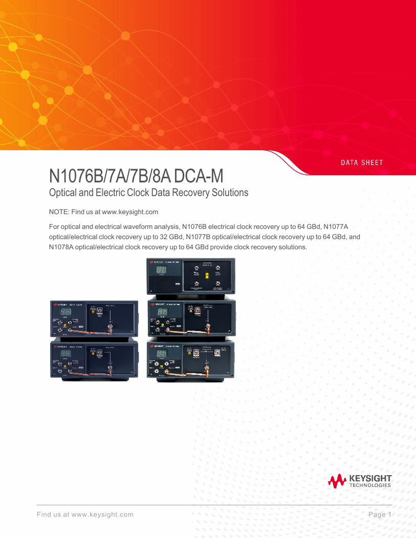
N1076B/7A/7B/8A DCA-M Optical and Electric Clock Data Recovery Solutions NOTE: Find us at www.keysight.com For optical and electrical waveform analysis, N1076B electrical clock recovery up to 64 GBd, N1077A optical/electrical clock recovery up to 32 GBd, N1077B optical/electrical clock recovery up to 64 GBd, and N1078A optical/electrical clock recovery up to 64 GBd provide clock recovery solutions. Find us at www.keysight.com Page 1
Transcript of Optical and Electrical Clock
N1076B/7A/7B/8ADCA-MOptical and Electric Clock Data Recovery SolutionsNOTE: Find us at www.keysight.com
For optical and electrical waveform analysis, N1076B electrical clock recovery up to 64 GBd, N1077Aoptical/electrical clock recovery up to 32 GBd, N1077B optical/electrical clock recovery up to 64 GBd, andN1078A optical/electrical clock recovery up to 64 GBd provide clock recovery solutions.
Find us at www.keysight.com Page 1
Table of Contents
Electrical and Optical Clock Recovery Solutions 4
PLL and jitter spectrum analysis 4
What Does Clock Recovery Do? 5
Why Use Clock Recovery? 6
Standards compliance 6
Clock-less devices 6
Electrical Clock Recovery 7
Optical/Electrical Clock Recovery 8
Characterize Next-generation Receivers and Transmitters 12
Recover clocks or clean-up clocks 12
Measure the real performance of clock-less devices 13
Perform more accurate jitter measurements and gain greater insight into the rootcause(s) of jitter 13
Easily control all settings 14
Application Example 15
Clock recovery for sampling scope with high-bandwidth sampling heads andprecision time base 15
N1076B Specifications 18
N1076B electrical data input (+/–) specifications 18
N1076B recovered clock output specifications 19
N1076B aux clock output specifications 1 20
N1076B environmental specifications 21
N1076B LINE power specifications 21
N1077A Specifications 22
N1077A electrical data input (+/–) specifications 22
N1077A recovered clock output specifications 22
N1077A aux clock output specifications 23
N1077A optical data input/output specifications 23
N1077A environmental specifications 24
N1077A LINE power specifications 25
N1077B Specifications 26
N1077B electrical data input (+/–) 26
N1077B optical data input/output specifications 27
Find us at www.keysight.com Page 2
N1077B minimum optical modulation amplitude (OMA) to achieve lock (Option SMM) 28
N1077B minimum optical modulation amplitude (OMA) to achieve lock (Option SXT) 29
N1077B recovered clock output specifications 30
N1077B aux clock interface output 31
N1077B environmental specifications 31
N1077B LINE power specifications 33
N1078A Specifications 34
N1078A electrical data input (+/–) 34
N1078A optical data input/output specifications 35
N1078A minimum optical modulation amplitude (OMA) to achieve lock (Option S50) 36
N1078A minimum optical modulation amplitude (OMA) to achieve lock (Option SXT) 37
N1078A recovered clock output specifications 38
N1078A aux clock output 1 39
N1078A environmental specifications 40
N1078A LINE power specifications 40
Ordering Information 41
N1076B configurations 41
N1077A configurations 42
N1077B configurations 43
N1078A configurations 44
Accessories 45
Find us at www.keysight.com Page 3
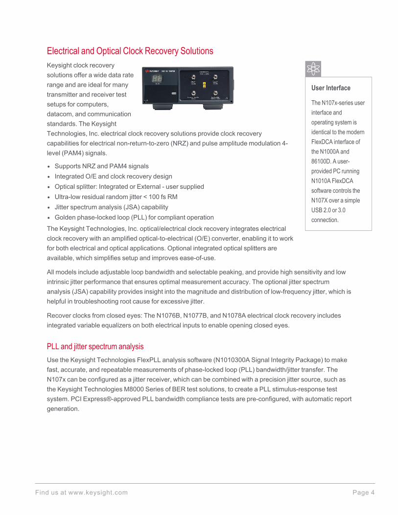
Electrical and Optical Clock Recovery Solutions
User Interface
The N107x-series userinterface andoperating system isidentical to the modernFlexDCA interface ofthe N1000A and86100D. A user-provided PC runningN1010A FlexDCAsoftware controls theN107X over a simpleUSB 2.0 or 3.0connection.
Keysight clock recoverysolutions offer a wide data raterange and are ideal for manytransmitter and receiver testsetups for computers,datacom, and communicationstandards. The KeysightTechnologies, Inc. electrical clock recovery solutions provide clock recoverycapabilities for electrical non-return-to-zero (NRZ) and pulse amplitude modulation 4-level (PAM4) signals.
l Supports NRZ and PAM4 signalsl Integrated O/E and clock recovery designl Optical splitter: Integrated or External - user suppliedl Ultra-low residual random jitter < 100 fs RMl Jitter spectrum analysis (JSA) capabilityl Golden phase-locked loop (PLL) for compliant operation
The Keysight Technologies, Inc. optical/electrical clock recovery integrates electricalclock recovery with an amplified optical-to-electrical (O/E) converter, enabling it to workfor both electrical and optical applications. Optional integrated optical splitters areavailable, which simplifies setup and improves ease-of-use.
All models include adjustable loop bandwidth and selectable peaking, and provide high sensitivity and lowintrinsic jitter performance that ensures optimal measurement accuracy. The optional jitter spectrumanalysis (JSA) capability provides insight into the magnitude and distribution of low-frequency jitter, which ishelpful in troubleshooting root cause for excessive jitter.
Recover clocks from closed eyes: The N1076B, N1077B, and N1078A electrical clock recovery includesintegrated variable equalizers on both electrical inputs to enable opening closed eyes.
PLL and jitter spectrum analysisUse the Keysight Technologies FlexPLL analysis software (N1010300A Signal Integrity Package) to makefast, accurate, and repeatable measurements of phase-locked loop (PLL) bandwidth/jitter transfer. TheN107x can be configured as a jitter receiver, which can be combined with a precision jitter source, such asthe Keysight Technologies M8000 Series of BER test solutions, to create a PLL stimulus-response testsystem. PCI Express®-approved PLL bandwidth compliance tests are pre-configured, with automatic reportgeneration.
Find us at www.keysight.com Page 4
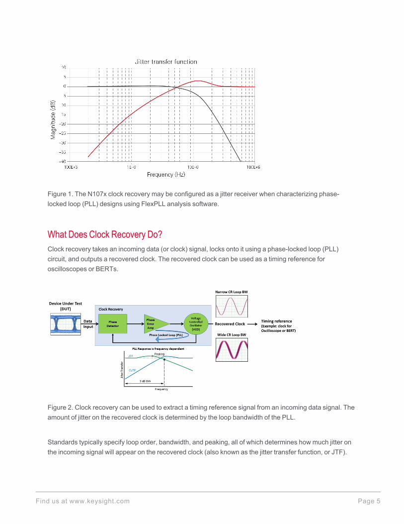
Figure 1. The N107x clock recovery may be configured as a jitter receiver when characterizing phase-locked loop (PLL) designs using FlexPLL analysis software.
What Does Clock Recovery Do?Clock recovery takes an incoming data (or clock) signal, locks onto it using a phase-locked loop (PLL)circuit, and outputs a recovered clock. The recovered clock can be used as a timing reference foroscilloscopes or BERTs.
Figure 2. Clock recovery can be used to extract a timing reference signal from an incoming data signal. Theamount of jitter on the recovered clock is determined by the loop bandwidth of the PLL.
Standards typically specify loop order, bandwidth, and peaking, all of which determines how much jitter onthe incoming signal will appear on the recovered clock (also known as the jitter transfer function, or JTF).
Find us at www.keysight.com Page 5
Users can configure the FlexDCA graphical user interface (GUI) to adjust these parameters and ensurestandards-compliant clock recovery (often referred to as a “golden PLL”).
Why Use Clock Recovery?
Standards complianceTo comply with standards such as IEEE 802.3 Ethernet, Fibre Channel, or the Optical Interworking Forum –Common Electrical Interface (OIF-CEI), clock recovery must be used when performing measurements suchas jitter, eye width, and/or eye height.
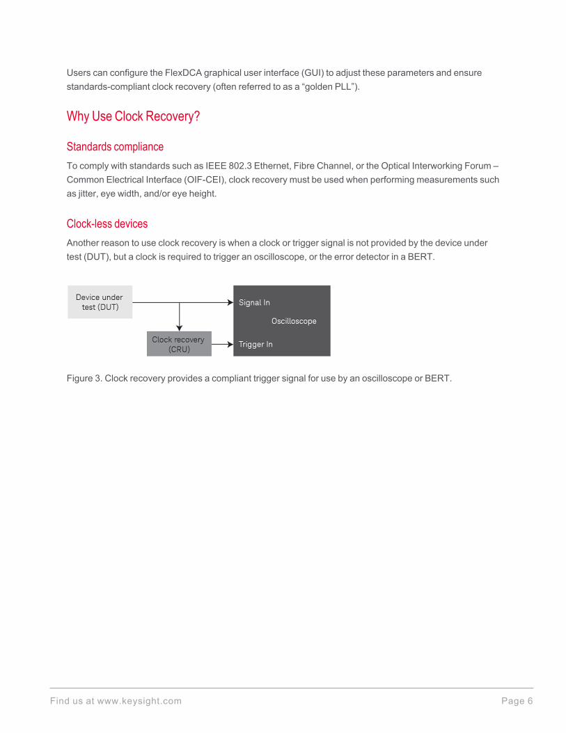
Clock-less devicesAnother reason to use clock recovery is when a clock or trigger signal is not provided by the device undertest (DUT), but a clock is required to trigger an oscilloscope, or the error detector in a BERT.
Figure 3. Clock recovery provides a compliant trigger signal for use by an oscilloscope or BERT.
Find us at www.keysight.com Page 6
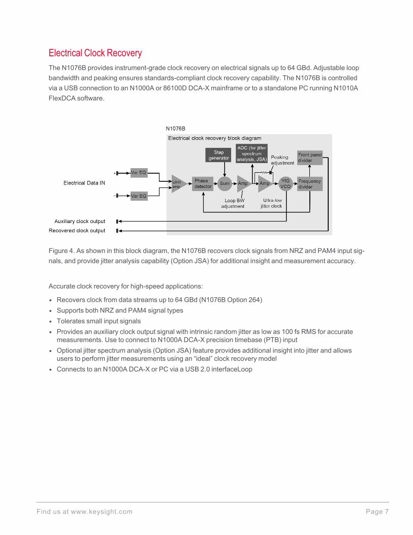
Electrical Clock RecoveryThe N1076B provides instrument-grade clock recovery on electrical signals up to 64 GBd. Adjustable loopbandwidth and peaking ensures standards-compliant clock recovery capability. The N1076B is controlledvia a USB connection to an N1000A or 86100D DCA-X mainframe or to a standalone PC running N1010AFlexDCA software.
Figure 4. As shown in this block diagram, the N1076B recovers clock signals from NRZ and PAM4 input sig-nals, and provide jitter analysis capability (Option JSA) for additional insight and measurement accuracy.
Accurate clock recovery for high-speed applications:
l Recovers clock from data streams up to 64 GBd (N1076B Option 264)l Supports both NRZ and PAM4 signal typesl Tolerates small input signalsl Provides an auxiliary clock output signal with intrinsic random jitter as low as 100 fs RMS for accuratemeasurements. Use to connect to N1000A DCA-X precision timebase (PTB) input
l Optional jitter spectrum analysis (Option JSA) feature provides additional insight into jitter and allowsusers to perform jitter measurements using an “ideal” clock recovery model
l Connects to an N1000A DCA-X or PC via a USB 2.0 interfaceLoop
Find us at www.keysight.com Page 7
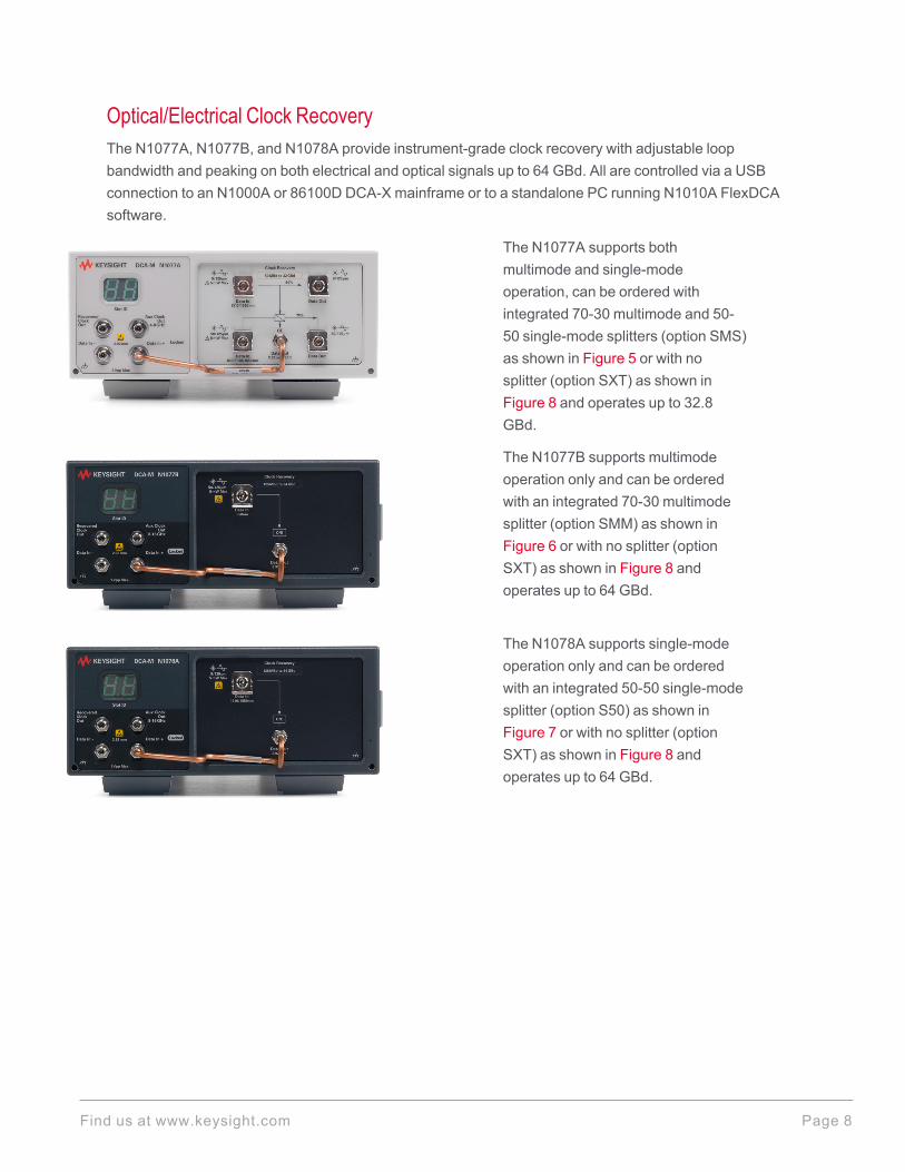
Optical/Electrical Clock RecoveryThe N1077A, N1077B, and N1078A provide instrument-grade clock recovery with adjustable loopbandwidth and peaking on both electrical and optical signals up to 64 GBd. All are controlled via a USBconnection to an N1000A or 86100D DCA-X mainframe or to a standalone PC running N1010A FlexDCAsoftware.
The N1077A supports bothmultimode and single-modeoperation, can be ordered withintegrated 70-30 multimode and 50-50 single-mode splitters (option SMS)as shown in Figure 5 or with nosplitter (option SXT) as shown inFigure 8 and operates up to 32.8GBd.
The N1077B supports multimodeoperation only and can be orderedwith an integrated 70-30 multimodesplitter (option SMM) as shown inFigure 6 or with no splitter (optionSXT) as shown in Figure 8 andoperates up to 64 GBd.
The N1078A supports single-modeoperation only and can be orderedwith an integrated 50-50 single-modesplitter (option S50) as shown inFigure 7 or with no splitter (optionSXT) as shown in Figure 8 andoperates up to 64 GBd.
Find us at www.keysight.com Page 8
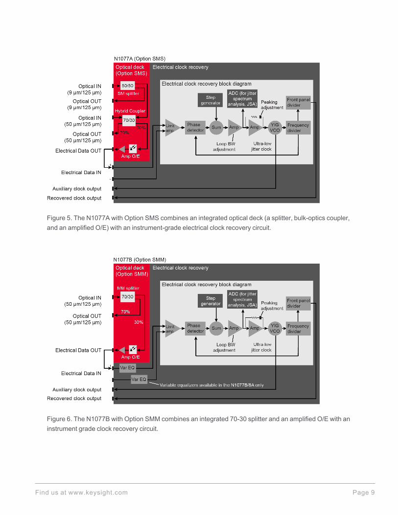
Figure 5. The N1077A with Option SMS combines an integrated optical deck (a splitter, bulk-optics coupler,and an amplified O/E) with an instrument-grade electrical clock recovery circuit.
Figure 6. The N1077B with Option SMM combines an integrated 70-30 splitter and an amplified O/E with aninstrument grade clock recovery circuit.
Find us at www.keysight.com Page 9
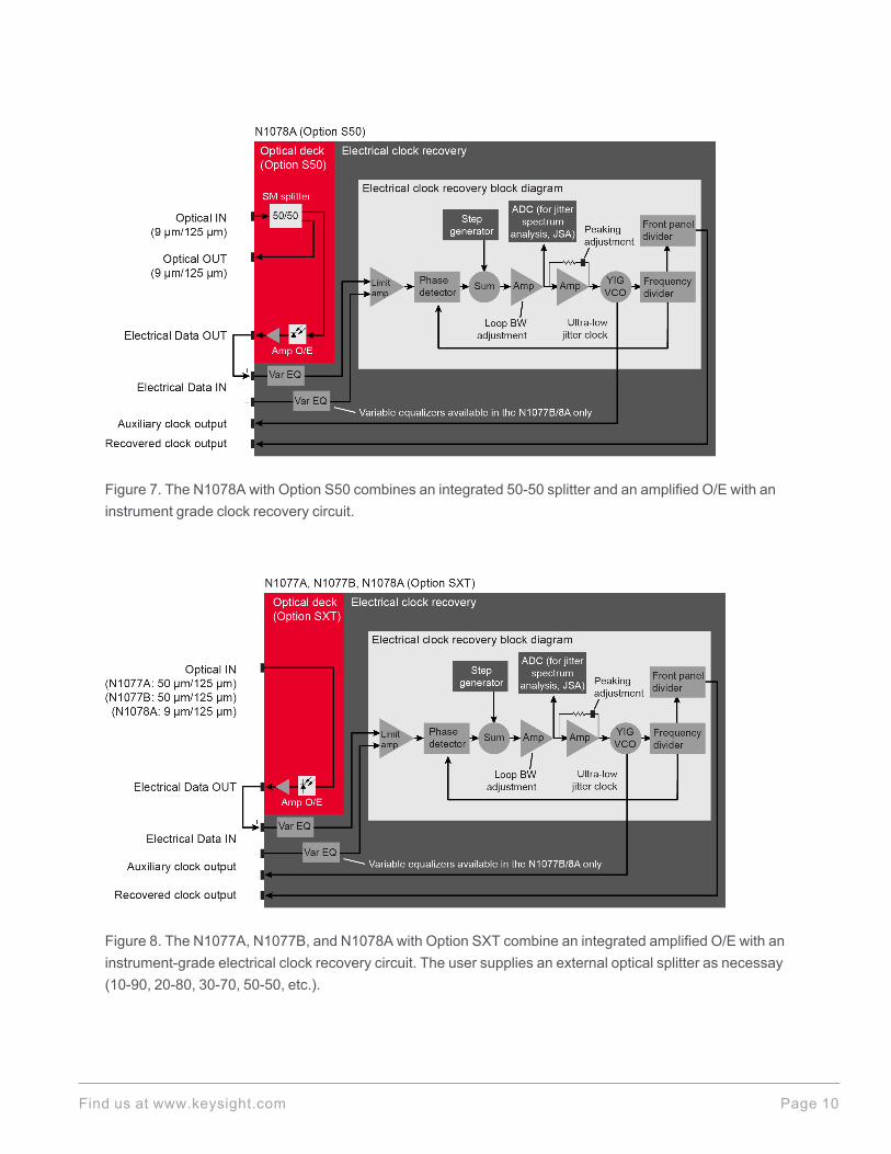
Figure 7. The N1078A with Option S50 combines an integrated 50-50 splitter and an amplified O/E with aninstrument grade clock recovery circuit.
Figure 8. The N1077A, N1077B, and N1078A with Option SXT combine an integrated amplified O/E with aninstrument-grade electrical clock recovery circuit. The user supplies an external optical splitter as necessay(10-90, 20-80, 30-70, 50-50, etc.).
Find us at www.keysight.com Page 10

Accurate, convenient solution for recovering clock signals from high-speed optical communication signals:
l Optional integrated splitter/coupler extracts a portion of the optical test signal using a built-in coupler.Main optical signal is returned to the front panel. Converts the tapped optical signal to an electrical signalusing an amplified O/E for greater sensitivity
l Recovers clock from data streams up to 64 GBd N1077B and N1078A (option 264)l Supports both NRZ and PAM4 signal typesl Provides an easy method for using the electrical clock recovery solution with optical signals
Find us at www.keysight.com Page 11
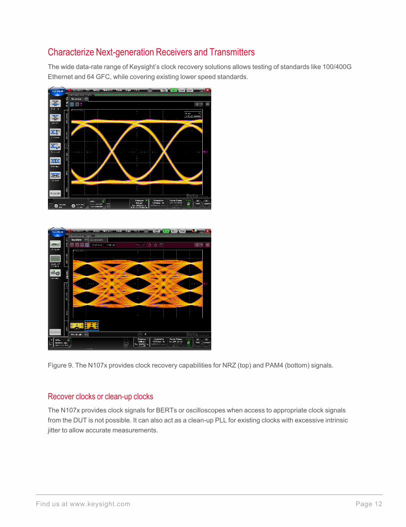
Characterize Next-generation Receivers and TransmittersThe wide data-rate range of Keysight’s clock recovery solutions allows testing of standards like 100/400GEthernet and 64 GFC, while covering existing lower speed standards.
Figure 9. The N107x provides clock recovery capabilities for NRZ (top) and PAM4 (bottom) signals.
Recover clocks or clean-up clocksThe N107x provides clock signals for BERTs or oscilloscopes when access to appropriate clock signalsfrom the DUT is not possible. It can also act as a clean-up PLL for existing clocks with excessive intrinsicjitter to allow accurate measurements.
Find us at www.keysight.com Page 12

Measure the real performance of clock-less devicesAccurate transmitter measurements are possible because of low intrinsic jitter, paired with tunable loopbandwidth, selectable peaking, and good sensitivity. The N107x’s auxiliary clock output provides ultra-lowintrinsic random jitter of less than 100 fs RMS, making it the ideal companion for sampling scopes equippedwith a precision time base.
Perform more accurate jitter measurements and gain greater insight into the root cause(s) of jitterJitter spectrum analysis (Option JSA) integrates a step generator and a low-noise, 14-bit ADC into the clockrecovery design (see Figure 5, Figure 6, Figure 7, and Figure 8). The step generator and ADC characterizethe clock recovery PLL in real-time, providing FlexDCA with the information that is necessary to calculatejitter at the input to the instrument. JSA uses this information to:
l Optimize the accuracy of random jitter measurements performed by Jitter mode (N1010100A R&D Pack-age)
l Emulate an “ideal” software clock recovery (CR) response; implement Golden PLL per standardsl Analyze the jitter spectrum of clock and data signals using jitter magnitude vs. frequency graphsl View the spectral distribution of low-frequency jitter and isolate jitter componentsl Perform band limited (integrated) TJ/DJ/RJ measurements; user-specified start/stop frequencies
Figure 10. Jitter spectrum analysis (N107xA Option JSA) optimizes Jitter Mode accuracy (N1010100A R&DPackage), measures low-frequency jitter (phase noise), and provides insight into the root cause(s) of jitter.
Find us at www.keysight.com Page 13
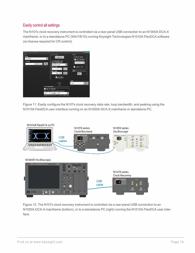
Easily control all settingsThe N107x clock recovery instrument is controlled via a rear-panel USB connection to an N1000A DCA-Xmainframe, or to a standalone PC (Win7/8/10) running Keysight Technologies N1010A FlexDCA software(no license required for CR control).
Figure 11. Easily configure the N107x clock recovery data rate, loop bandwidth, and peaking using theN1010A FlexDCA user interface running on an N1000A DCA-X mainframe or standalone PC.
Figure 12. The N107x clock recovery instrument is controlled via a rear-panel USB connection to anN1000A DCA-X mainframe (bottom), or to a standalone PC (right) running the N1010A FlexDCA user inter-face.
Find us at www.keysight.com Page 14

Application Example
Clock recovery for sampling scope with high-bandwidth sampling heads and precision time baseSampling scopes are the ideal choice for transmitter characterization when high-bandwidth, low noise floorand low intrinsic jitter are required. The N107x, with its ultra-low jitter auxiliary clock output, provides a cleansine wave for a precision time-base module or integrated precision timebase enabling the most accuratemeasurements (precision timebase is not required). The main recovered clock output, with its divide stages,triggers the front panel trigger input. For additional Application Examples see the Keysight N107X-SeriesClock Recovery DCA-Ms User’s Guide, N1076-90003. Go to www.keysight.com/find/N1077A and click theResource Center tab.
Find us at www.keysight.com Page 15
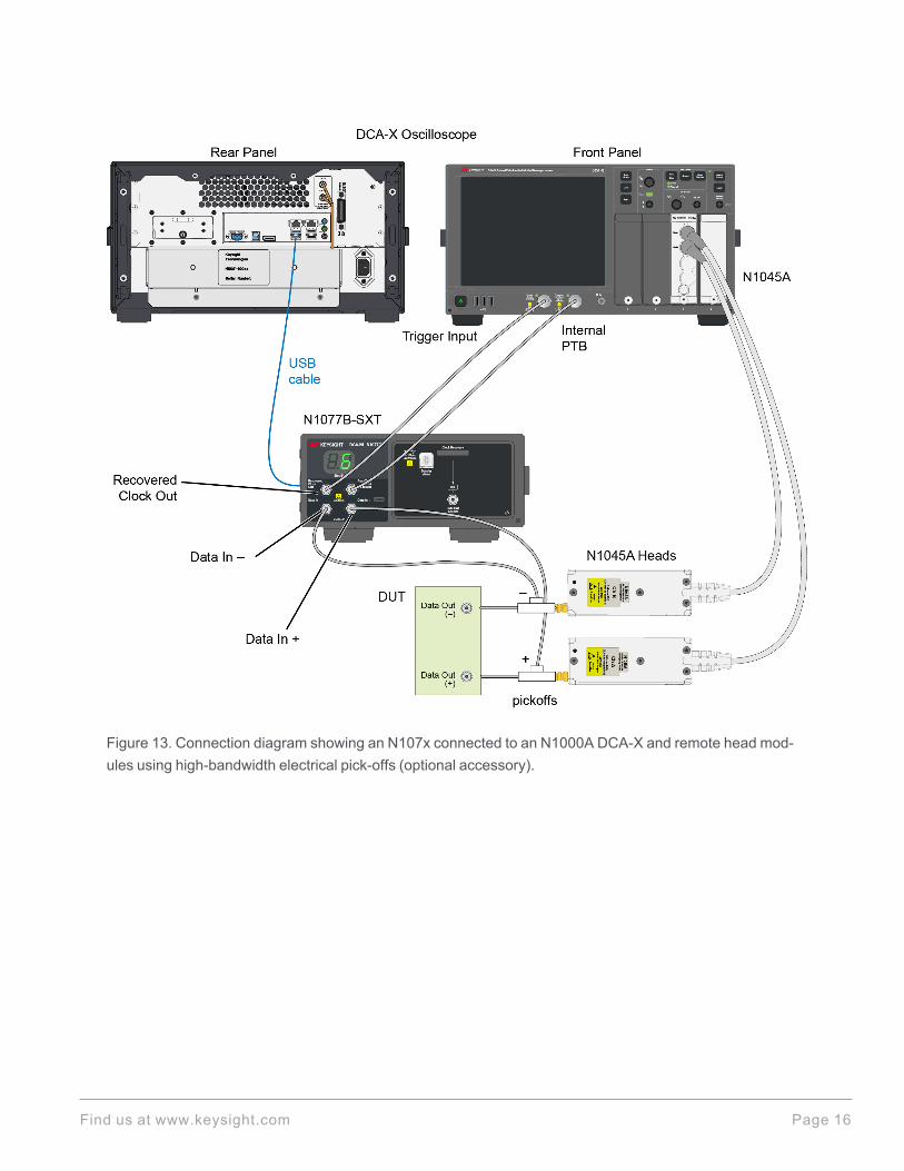
Figure 13. Connection diagram showing an N107x connected to an N1000A DCA-X and remote head mod-ules using high-bandwidth electrical pick-offs (optional accessory).
Find us at www.keysight.com Page 16
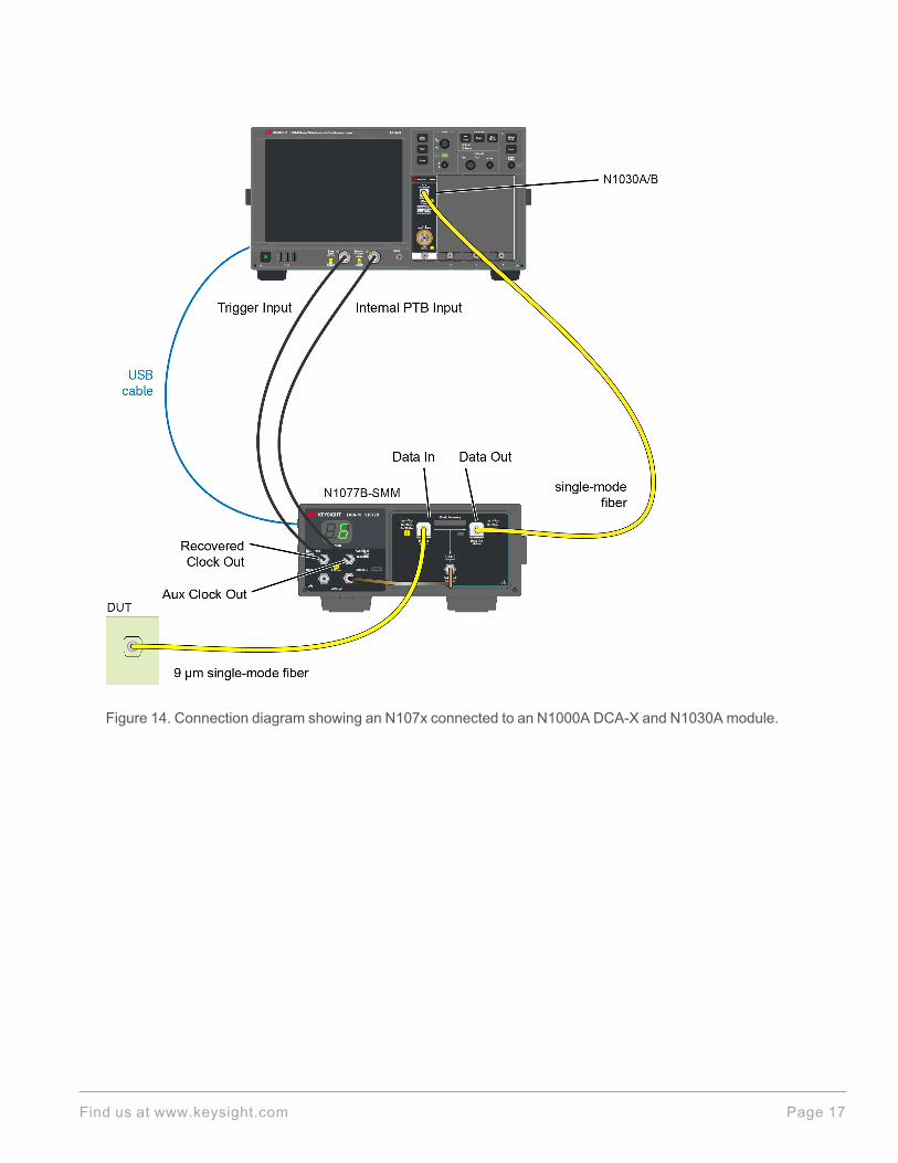
Figure 14. Connection diagram showing an N107x connected to an N1000A DCA-X and N1030A module.
Find us at www.keysight.com Page 17
N1076B Specifications
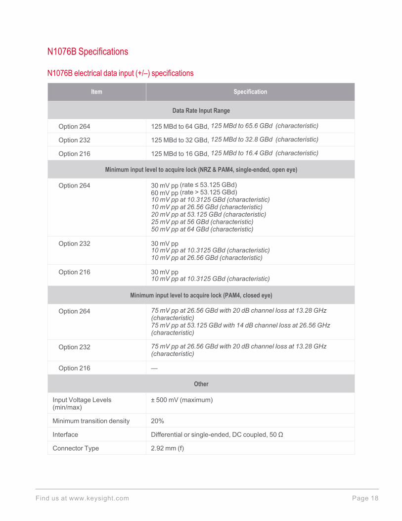
N1076B electrical data input (+/–) specifications
Item Specification
Data Rate Input Range
Option 264 125 MBd to 64 GBd, 125 MBd to 65.6 GBd (characteristic)
Option 232 125 MBd to 32 GBd, 125 MBd to 32.8 GBd (characteristic)
Option 216 125 MBd to 16 GBd, 125 MBd to 16.4 GBd (characteristic)
Minimum input level to acquire lock (NRZ & PAM4, single-ended, open eye)
Option 264 30 mV pp (rate ≤ 53.125 GBd)60 mV pp (rate > 53.125 GBd)10 mV pp at 10.3125 GBd (characteristic)10 mV pp at 26.56 GBd (characteristic)20 mV pp at 53.125 GBd (characteristic)25 mV pp at 56 GBd (characteristic)50 mV pp at 64 GBd (characteristic)
Option 232 30 mV pp10 mV pp at 10.3125 GBd (characteristic)10 mV pp at 26.56 GBd (characteristic)
Option 216 30 mV pp10 mV pp at 10.3125 GBd (characteristic)
Minimum input level to acquire lock (PAM4, closed eye)
Option 264 75 mV pp at 26.56 GBd with 20 dB channel loss at 13.28 GHz(characteristic)75 mV pp at 53.125 GBd with 14 dB channel loss at 26.56 GHz(characteristic)
Option 232 75 mV pp at 26.56 GBd with 20 dB channel loss at 13.28 GHz(characteristic)
Option 216 —
Other
Input Voltage Levels(min/max)
± 500 mV (maximum)
Minimum transition density 20%
Interface Differential or single-ended, DC coupled, 50 Ω
Connector Type 2.92 mm (f)
Find us at www.keysight.com Page 18
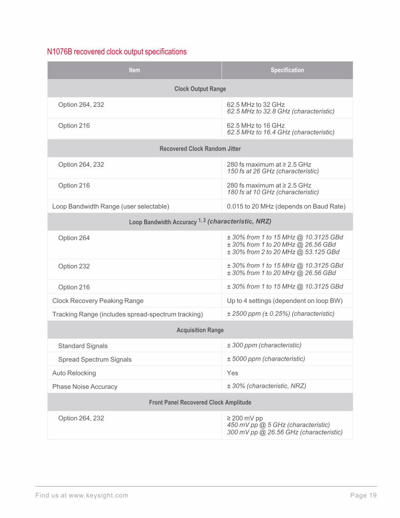
N1076B recovered clock output specifications
Item Specification
Clock Output Range
Option 264, 232 62.5 MHz to 32 GHz62.5 MHz to 32.8 GHz (characteristic)
Option 216 62.5 MHz to 16 GHz62.5 MHz to 16.4 GHz (characteristic)
Recovered Clock Random Jitter
Option 264, 232 280 fs maximum at ≥ 2.5 GHz150 fs at 26 GHz (characteristic)
Option 216 280 fs maximum at ≥ 2.5 GHz180 fs at 10 GHz (characteristic)
Loop Bandwidth Range (user selectable) 0.015 to 20 MHz (depends on Baud Rate)
Loop Bandwidth Accuracy 1, 2 (characteristic, NRZ)
Option 264 ± 30% from 1 to 15 MHz@ 10.3125 GBd± 30% from 1 to 20 MHz@ 26.56 GBd± 30% from 2 to 20 MHz@ 53.125 GBd
Option 232 ± 30% from 1 to 15 MHz@ 10.3125 GBd± 30% from 1 to 20 MHz@ 26.56 GBd
Option 216 ± 30% from 1 to 15 MHz@ 10.3125 GBd
Clock Recovery Peaking Range Up to 4 settings (dependent on loop BW)
Tracking Range (includes spread-spectrum tracking) ± 2500 ppm (± 0.25%) (characteristic)
Acquisition Range
Standard Signals ± 300 ppm (characteristic)
Spread Spectrum Signals ± 5000 ppm (characteristic)
Auto Relocking Yes
Phase Noise Accuracy ± 30% (characteristic, NRZ)
Front Panel Recovered Clock Amplitude
Option 264, 232 ≥ 200 mV pp450 mV pp@ 5 GHz (characteristic)300 mV pp@ 26.56 GHz (characteristic)
Find us at www.keysight.com Page 19
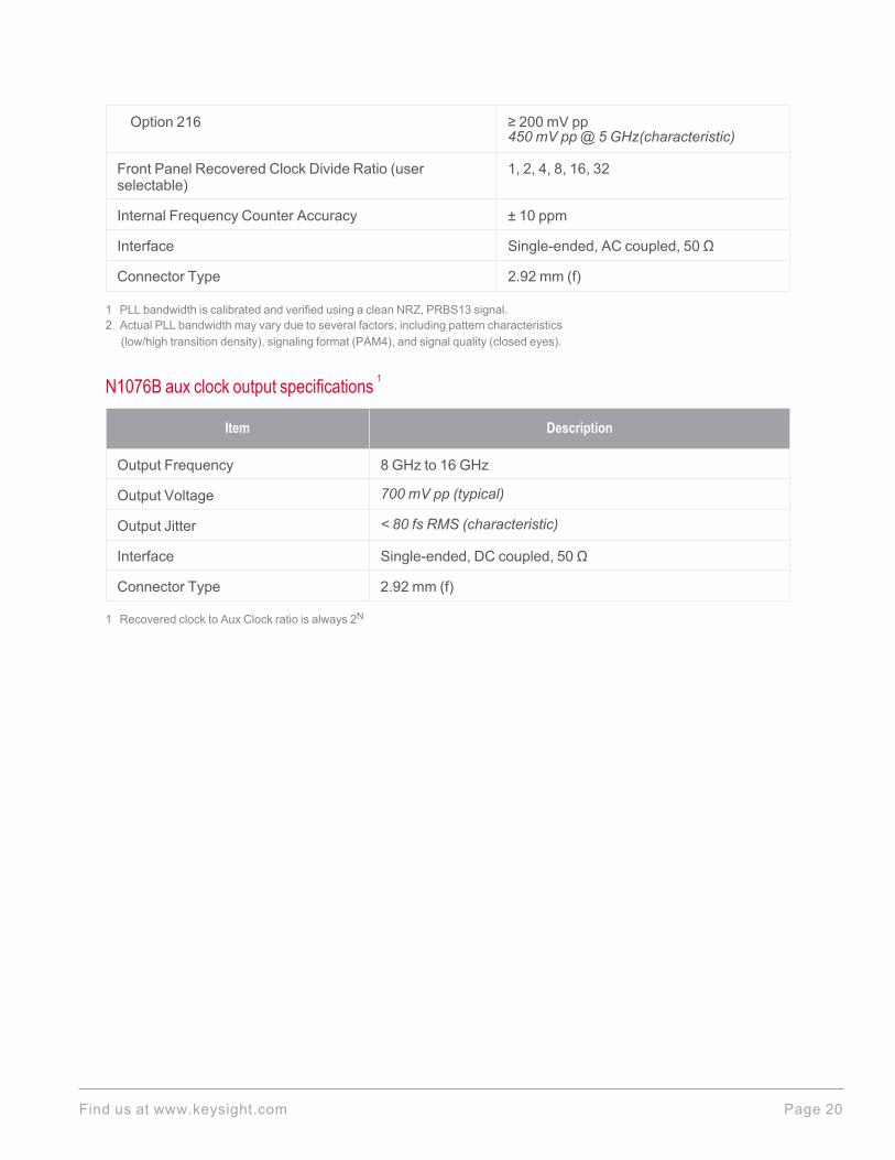
Option 216 ≥ 200 mV pp450 mV pp@ 5 GHz(characteristic)
Front Panel Recovered Clock Divide Ratio (userselectable)
1, 2, 4, 8, 16, 32
Internal Frequency Counter Accuracy ± 10 ppm
Interface Single-ended, AC coupled, 50 Ω
Connector Type 2.92 mm (f)
1 PLL bandwidth is calibrated and verified using a clean NRZ, PRBS13 signal.2 Actual PLL bandwidth may vary due to several factors, including pattern characteristics
(low/high transition density), signaling format (PAM4), and signal quality (closed eyes).
N1076B aux clock output specifications 1
Item Description
Output Frequency 8 GHz to 16 GHz
Output Voltage 700 mV pp (typical)
Output Jitter < 80 fs RMS (characteristic)
Interface Single-ended, DC coupled, 50 Ω
Connector Type 2.92 mm (f)
1 Recovered clock to Aux Clock ratio is always 2N
Find us at www.keysight.com Page 20
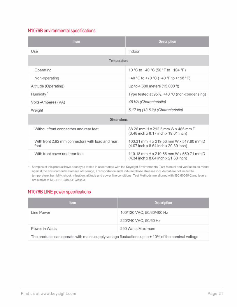
N1076B environmental specifications
Item Description
Use Indoor
Temperature
Operating 10 °C to +40 °C (50 °F to +104 °F)
Non-operating −40 °C to +70 °C (−40 °F to +158 °F)
Altitude (Operating) Up to 4,600 meters (15,000 ft)
Humidity 1 Type tested at 95%, +40 °C (non-condensing)
Volts-Amperes (VA) 48 VA (Characteristic)
Weight 6.17 kg (13.6 lb) (Characteristic)
Dimensions
Without front connectors and rear feet 88.26 mm H x 212.5 mm W x 485 mm D(3.48 inch x 8.17 inch x 19.01 inch)
With front 2.92 mm connectors with load and rearfeet
103.31 mm H x 219.56 mm W x 517.80 mm D(4.07 inch x 8.64 inch x 20.39 inch)
With front cover and rear feet 110.18 mm H x 219.56 mm W x 550.71 mm D(4.34 inch x 8.64 inch x 21.68 inch)
1 Samples of this product have been type tested in accordance with the Keysight Environmental Test Manual and verified to be robustagainst the environmental stresses of Storage, Transportation and End-use; those stresses include but are not limited totemperature, humidity, shock, vibration, altitude and power line conditions. Test Methods are aligned with IEC 60068-2 and levelsare similar to MIL-PRF-28800F Class 3.
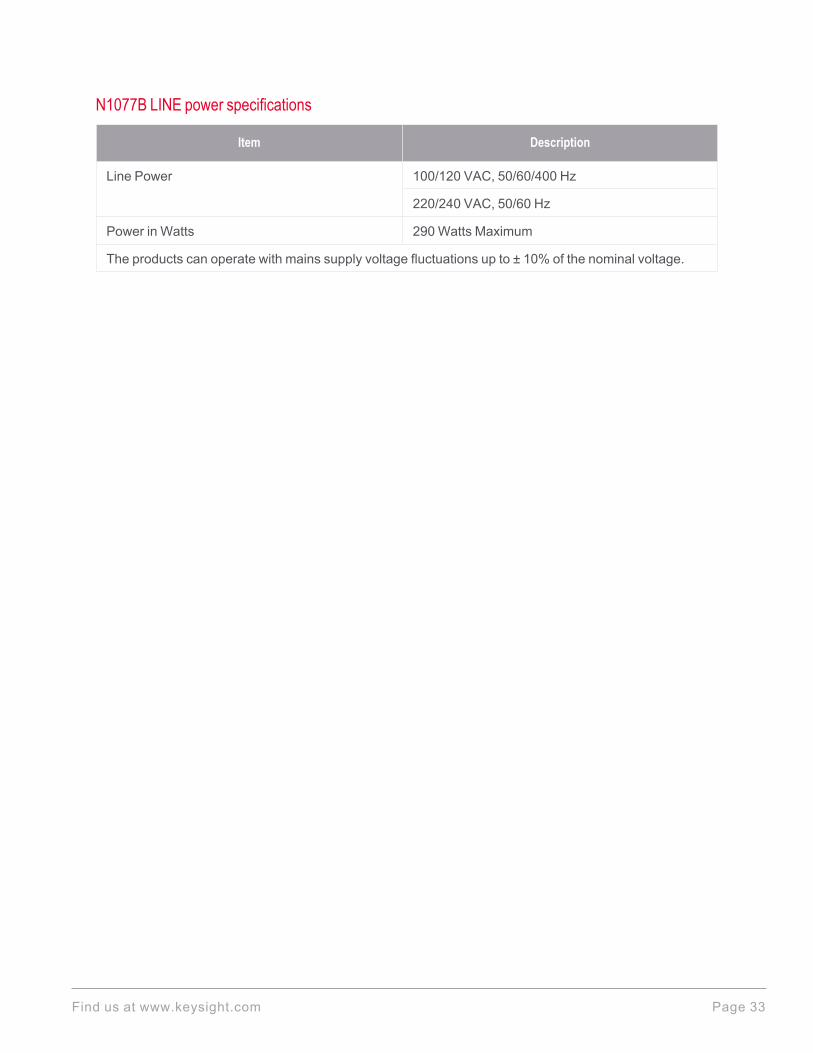
N1076B LINE power specifications
Item Description
Line Power 100/120 VAC, 50/60/400 Hz
220/240 VAC, 50/60 Hz
Power in Watts 290 Watts Maximum
The products can operate with mains supply voltage fluctuations up to ± 10% of the nominal voltage.
Find us at www.keysight.com Page 21
N1077A Specifications
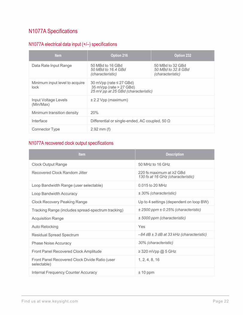
N1077A electrical data input (+/–) specifications
Item Option 216 Option 232
Data Rate Input Range 50 MBd to 16 GBd50 MBd to 16.4 GBd(characteristic)
50 MBd to 32 GBd50 MBd to 32.8 GBd(characteristic)
Minimum input level to acquirelock
30 mVpp (rate ≤ 27 GBd)35 mVpp (rate > 27 GBd)25 mV pp at 25 GBd (characteristic)
Input Voltage Levels(Min/Max)
± 2.2 Vpp (maximum)
Minimum transition density 20%
Interface Differential or single-ended, AC coupled, 50 Ω
Connector Type 2.92 mm (f)
N1077A recovered clock output specifications
Item Description
Clock Output Range 50 MHz to 16 GHz
Recovered Clock Random Jitter 220 fs maximum at ≥2 GBd130 fs at 16 GHz (characteristic)
Loop Bandwidth Range (user selectable) 0.015 to 20 MHz
Loop Bandwidth Accuracy ± 30% (characteristic)
Clock Recovery Peaking Range Up to 4 settings (dependent on loop BW)
Tracking Range (includes spread-spectrum tracking) ± 2500 ppm ± 0.25% (characteristic)
Acquisition Range ± 5000 ppm (characteristic)
Auto Relocking Yes
Residual Spread Spectrum –84 dB ± 3 dB at 33 kHz (characteristic)
Phase Noise Accuracy 30% (characteristic)
Front Panel Recovered Clock Amplitude ≥ 320 mVpp@ 5 GHz
Front Panel Recovered Clock Divide Ratio (userselectable)
1, 2, 4, 8, 16
Internal Frequency Counter Accuracy ± 10 ppm
Find us at www.keysight.com Page 22
Interface Single-ended, AC coupled, 50 Ω
Connector Type 2.92 mm (f)
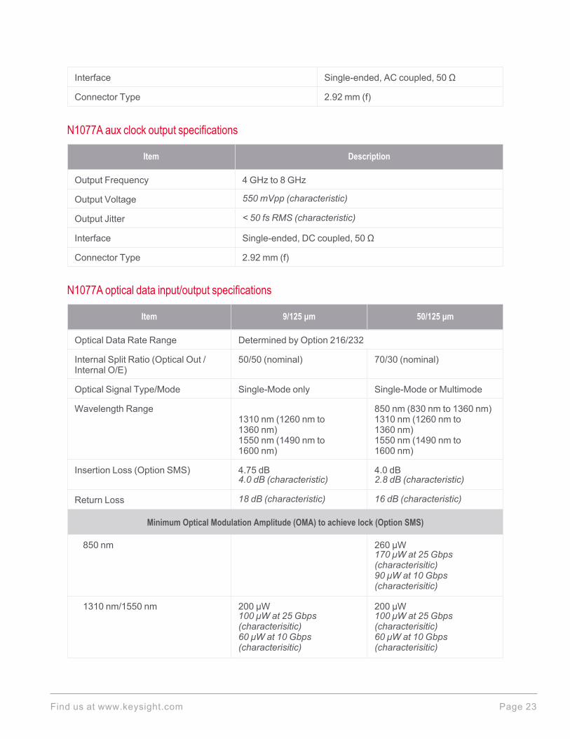
N1077A aux clock output specifications
Item Description
Output Frequency 4 GHz to 8 GHz
Output Voltage 550 mVpp (characteristic)
Output Jitter < 50 fs RMS (characteristic)
Interface Single-ended, DC coupled, 50 Ω
Connector Type 2.92 mm (f)
N1077A optical data input/output specifications
Item 9/125 μm 50/125 μm
Optical Data Rate Range Determined by Option 216/232
Internal Split Ratio (Optical Out /Internal O/E)
50/50 (nominal) 70/30 (nominal)
Optical Signal Type/Mode Single-Mode only Single-Mode or Multimode
Wavelength Range1310 nm (1260 nm to1360 nm)1550 nm (1490 nm to1600 nm)
850 nm (830 nm to 1360 nm)1310 nm (1260 nm to1360 nm)1550 nm (1490 nm to1600 nm)
Insertion Loss (Option SMS) 4.75 dB4.0 dB (characteristic)
4.0 dB2.8 dB (characteristic)
Return Loss 18 dB (characteristic) 16 dB (characteristic)
Minimum Optical Modulation Amplitude (OMA) to achieve lock (Option SMS)
850 nm 260 μW170 μW at 25 Gbps (characterisitic)90 μW at 10 Gbps (characterisitic)
1310 nm/1550 nm 200 μW100 μW at 25 Gbps (characterisitic)60 μW at 10 Gbps (characterisitic)
200 μW100 μW at 25 Gbps (characterisitic)60 μW at 10 Gbps (characterisitic)
Find us at www.keysight.com Page 23
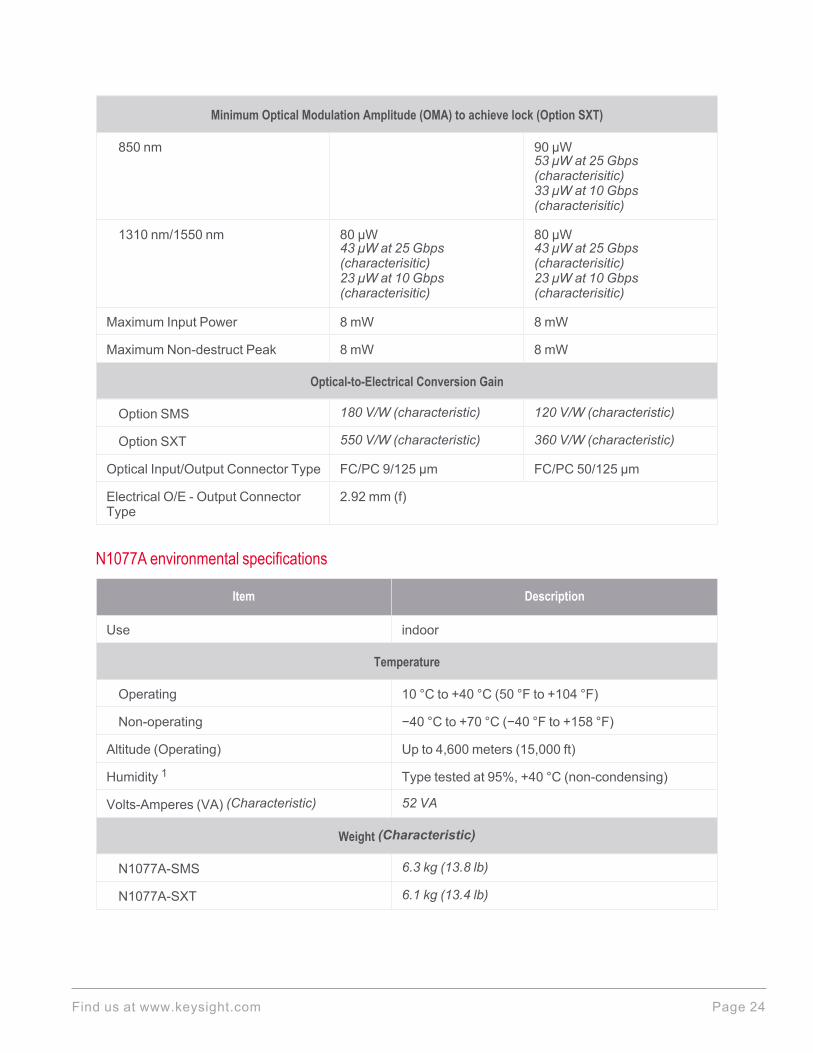
Minimum Optical Modulation Amplitude (OMA) to achieve lock (Option SXT)
850 nm 90 μW53 μW at 25 Gbps (characterisitic)33 μW at 10 Gbps (characterisitic)
1310 nm/1550 nm 80 μW43 μW at 25 Gbps (characterisitic)23 μW at 10 Gbps (characterisitic)
80 μW43 μW at 25 Gbps (characterisitic)23 μW at 10 Gbps (characterisitic)
Maximum Input Power 8 mW 8 mW
Maximum Non-destruct Peak 8 mW 8 mW
Optical-to-Electrical Conversion Gain
Option SMS 180 V/W (characteristic) 120 V/W (characteristic)
Option SXT 550 V/W (characteristic) 360 V/W (characteristic)
Optical Input/Output Connector Type FC/PC 9/125 μm FC/PC 50/125 μm
Electrical O/E - Output ConnectorType
2.92 mm (f)
N1077A environmental specifications
Item Description
Use indoor
Temperature
Operating 10 °C to +40 °C (50 °F to +104 °F)
Non-operating −40 °C to +70 °C (−40 °F to +158 °F)
Altitude (Operating) Up to 4,600 meters (15,000 ft)
Humidity 1 Type tested at 95%, +40 °C (non-condensing)
Volts-Amperes (VA) (Characteristic) 52 VA
Weight (Characteristic)
N1077A-SMS 6.3 kg (13.8 lb)
N1077A-SXT 6.1 kg (13.4 lb)
Find us at www.keysight.com Page 24
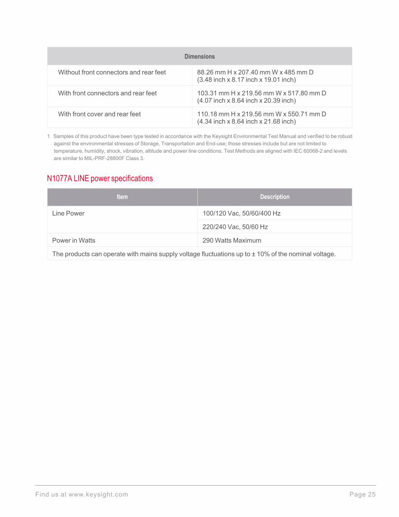
Dimensions
Without front connectors and rear feet 88.26 mm H x 207.40 mm W x 485 mm D(3.48 inch x 8.17 inch x 19.01 inch)
With front connectors and rear feet 103.31 mm H x 219.56 mm W x 517.80 mm D(4.07 inch x 8.64 inch x 20.39 inch)
With front cover and rear feet 110.18 mm H x 219.56 mm W x 550.71 mm D(4.34 inch x 8.64 inch x 21.68 inch)
1 Samples of this product have been type tested in accordance with the Keysight Environmental Test Manual and verified to be robustagainst the environmental stresses of Storage, Transportation and End-use; those stresses include but are not limited totemperature, humidity, shock, vibration, altitude and power line conditions. Test Methods are aligned with IEC 60068-2 and levelsare similar to MIL-PRF-28800F Class 3.
N1077A LINE power specifications
Item Description
Line Power 100/120 Vac, 50/60/400 Hz
220/240 Vac, 50/60 Hz
Power in Watts 290 Watts Maximum
The products can operate with mains supply voltage fluctuations up to ± 10% of the nominal voltage.
Find us at www.keysight.com Page 25
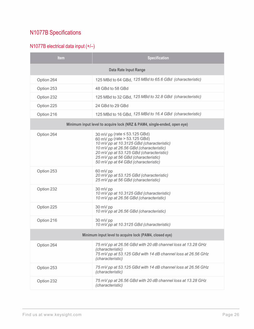
N1077B Specifications
N1077B electrical data input (+/–)
Item Specification
Data Rate Input Range
Option 264 125 MBd to 64 GBd, 125 MBd to 65.6 GBd (characteristic)
Option 253 48 GBd to 58 GBd
Option 232 125 MBd to 32 GBd, 125 MBd to 32.8 GBd (characteristic)
Option 225 24 GBd to 29 GBd
Option 216 125 MBd to 16 GBd, 125 MBd to 16.4 GBd (characteristic)
Minimum input level to acquire lock (NRZ & PAM4, single-ended, open eye)
Option 264 30 mV pp (rate ≤ 53.125 GBd)60 mV pp (rate > 53.125 GBd)10 mV pp at 10.3125 GBd (characteristic)10 mV pp at 26.56 GBd (characteristic)20 mV pp at 53.125 GBd (characteristic)25 mV pp at 56 GBd (characteristic)50 mV pp at 64 GBd (characteristic)
Option 253 60 mV pp20 mV pp at 53.125 GBd (characteristic)25 mV pp at 56 GBd (characteristic)
Option 232 30 mV pp10 mV pp at 10.3125 GBd (characteristic)10 mV pp at 26.56 GBd (characteristic)
Option 225 30 mV pp10 mV pp at 26.56 GBd (characteristic)
Option 216 30 mV pp10 mV pp at 10.3125 GBd (characteristic)
Minimum input level to acquire lock (PAM4, closed eye)
Option 264 75 mV pp at 26.56 GBd with 20 dB channel loss at 13.28 GHz(characteristic)75 mV pp at 53.125 GBd with 14 dB channel loss at 26.56 GHz(characteristic)
Option 253 75 mV pp at 53.125 GBd with 14 dB channel loss at 26.56 GHz(characteristic)
Option 232 75 mV pp at 26.56 GBd with 20 dB channel loss at 13.28 GHz(characteristic)
Find us at www.keysight.com Page 26

Option 225 75 mV pp at 26.56 GBd with 20 dB channel loss at 13.28 GHz(characteristic)
Other
Input Voltage Levels(min/max)
± 500 mV (maximum)
Interface Differential or single-ended, DC coupled, 50 Ω
Connector Type 2.92 mm (f)
N1077B optical data input/output specifications
Item Description
Data Rate Input Range
Option 264 125 MBd to 64 GBd125 MBd to 65.6 GBd (characteristic)
Option 253 48 GBd to 58 GBd
Option 232 125 MBd to 32 GBd125 MBd to 32.8 GBd (characteristic)
Option 225 24 GBd to 29 GBd
Option 216 125 MBd to 16 GBd125 MBd to 16.4 GBd (characteristic)
Internal Split Ratio (Option SMM)(Optical Out / Internal O/E)
70/30 (nominal)
Wavelength Range
Option SMM 840 nm – 900 nm900 nm – 950 nm (characteristic)
Option SXT 840 nm – 950 nm
Insertion Loss (Option SMM) 3.75 mW2.3 mW (characteristic)
Return Loss 16 dB (characteristic)
Maximum Input Power
Option SMM 8 mW
Option SXT 5 mW
Optical Input/Output Connector Type FC/PC 50/125 μm
O/E Data Output Connector Type 2.92 mm (f)
Find us at www.keysight.com Page 27

N1077B minimum optical modulation amplitude (OMA) to achieve lock (Option SMM)
Item Description
NRZ and PAM4 (OMA) 850 nm
Option 264 200 μW (rate ≤ 53.125 GBd)400 μW (53.125 GBd < rate ≤ 59 GBd)60 μW at 10.3125 GBd (characteristic)80 μW at 26.56 GBd (characteristic)80 μW at 53.125 GBd (characteristic)150 μW at 56 GBd (characteristic)300 μW at 64 GBd (characteristic)
Option 253 400 μW80 μW at 53.125 GBd (characteristic)150 μW at 56 GBd (characteristic)
Option 232 200 μW60 μW at 10.3125 GBd (characteristic)80 μW at 26.56 GBd (characteristic)
Option 225 200 μW80 μW at 26.56 GBd (characteristic)
Option 216 200 μW60 μW at 10.3125 GBd (characteristic)
PAM4 Stressed Eye 850 nm (Clock recovery locks under these conditions)
Baud Rate Pattern Outer OMA TDECQ
Option 264 26.56 GBd SSPRQ –5.1 dBm ~3.4 dB
53.125 GBd SSPRQ –0.8 dBm ~3.4 dB
Option 253 53.125 GBd SSPRQ –0.8 dBm ~3.4 dB
Options 225, 232 26.56 GBd SSPRQ –5.1 dBm ~3.4 dB
Find us at www.keysight.com Page 28
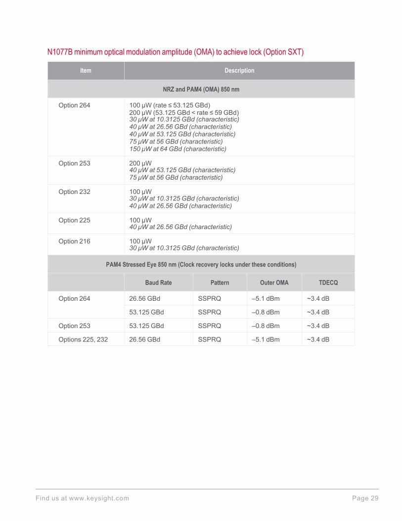
N1077B minimum optical modulation amplitude (OMA) to achieve lock (Option SXT)
Item Description
NRZ and PAM4 (OMA) 850 nm
Option 264 100 μW (rate ≤ 53.125 GBd)200 μW (53.125 GBd < rate ≤ 59 GBd)30 μW at 10.3125 GBd (characteristic)40 μW at 26.56 GBd (characteristic)40 μW at 53.125 GBd (characteristic)75 μW at 56 GBd (characteristic)150 μW at 64 GBd (characteristic)
Option 253 200 μW40 μW at 53.125 GBd (characteristic)75 μW at 56 GBd (characteristic)
Option 232 100 μW30 μW at 10.3125 GBd (characteristic)40 μW at 26.56 GBd (characteristic)
Option 225 100 μW40 μW at 26.56 GBd (characteristic)
Option 216 100 μW30 μW at 10.3125 GBd (characteristic)
PAM4 Stressed Eye 850 nm (Clock recovery locks under these conditions)
Baud Rate Pattern Outer OMA TDECQ
Option 264 26.56 GBd SSPRQ –5.1 dBm ~3.4 dB
53.125 GBd SSPRQ –0.8 dBm ~3.4 dB
Option 253 53.125 GBd SSPRQ –0.8 dBm ~3.4 dB
Options 225, 232 26.56 GBd SSPRQ –5.1 dBm ~3.4 dB
Find us at www.keysight.com Page 29
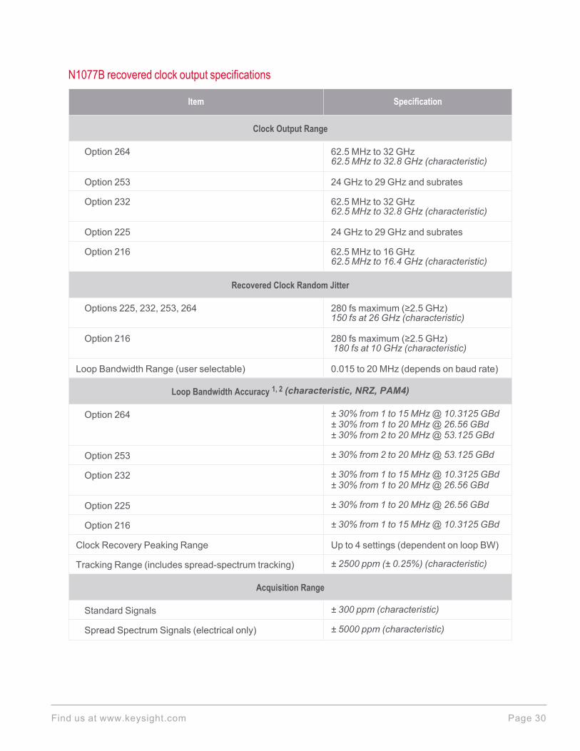
N1077B recovered clock output specifications
Item Specification
Clock Output Range
Option 264 62.5 MHz to 32 GHz62.5 MHz to 32.8 GHz (characteristic)
Option 253 24 GHz to 29 GHz and subrates
Option 232 62.5 MHz to 32 GHz62.5 MHz to 32.8 GHz (characteristic)
Option 225 24 GHz to 29 GHz and subrates
Option 216 62.5 MHz to 16 GHz62.5 MHz to 16.4 GHz (characteristic)
Recovered Clock Random Jitter
Options 225, 232, 253, 264 280 fs maximum (≥2.5 GHz)150 fs at 26 GHz (characteristic)
Option 216 280 fs maximum (≥2.5 GHz)180 fs at 10 GHz (characteristic)
Loop Bandwidth Range (user selectable) 0.015 to 20 MHz (depends on baud rate)
Loop Bandwidth Accuracy 1, 2 (characteristic, NRZ, PAM4)
Option 264 ± 30% from 1 to 15 MHz@ 10.3125 GBd± 30% from 1 to 20 MHz@ 26.56 GBd± 30% from 2 to 20 MHz@ 53.125 GBd
Option 253 ± 30% from 2 to 20 MHz@ 53.125 GBd
Option 232 ± 30% from 1 to 15 MHz@ 10.3125 GBd± 30% from 1 to 20 MHz@ 26.56 GBd
Option 225 ± 30% from 1 to 20 MHz@ 26.56 GBd
Option 216 ± 30% from 1 to 15 MHz@ 10.3125 GBd
Clock Recovery Peaking Range Up to 4 settings (dependent on loop BW)
Tracking Range (includes spread-spectrum tracking) ± 2500 ppm (± 0.25%) (characteristic)
Acquisition Range
Standard Signals ± 300 ppm (characteristic)
Spread Spectrum Signals (electrical only) ± 5000 ppm (characteristic)
Find us at www.keysight.com Page 30
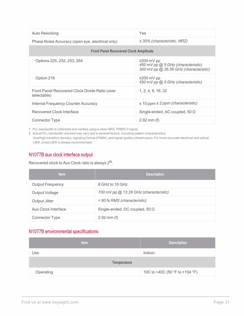
Auto Relocking Yes
Phase Noise Accuracy (open eye, electrical only) ± 30% (characteristic, NRZ)
Front Panel Recovered Clock Amplitude
Options 225, 232, 253, 264 ≥200 mV pp450 mV pp@ 5 GHz (characteristic)300 mV pp@ 26.56 GHz (characteristic)
Option 216 ≥200 mV pp450 mV pp@ 5 GHz (characteristic)
Front Panel Recovered Clock Divide Ratio (userselectable)
1, 2, 4, 8, 16, 32
Internal Frequency Counter Accuracy ± 10 ppm ± 2 ppm (characteristic)
Recovered Clock Interface Single-ended, AC coupled, 50 Ω
Connector Type 2.92 mm (f)
1 PLL bandwidth is calibrated and verified using a clean NRZ, PRBS13 signal.2 Actual PLL bandwidth untuned may vary due to several factors, including pattern characteristics
(low/high transition density), signaling format (PAM4), and signal quality (closed eyes). For more accurate electrical and opticalLBW, tuned LBW is always recommended.
N1077B aux clock interface outputRecovered clock to Aux Clock ratio is always 2N.
Item Description
Output Frequency 8 GHz to 16 GHz
Output Voltage 700 mV pp @ 13.28 GHz (characteristic)
Output Jitter < 80 fs RMS (characteristic)
Aux Clock Interface Single-ended, DC coupled, 50 Ω
Connector Type 2.92 mm (f)
N1077B environmental specifications
Item Description
Use Indoor
Temperature
Operating 10C to +40C (50 °F to +104 °F)
Find us at www.keysight.com Page 31
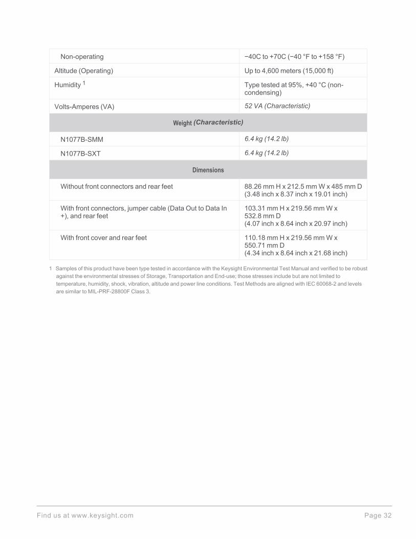
Non-operating −40C to +70C (−40 °F to +158 °F)
Altitude (Operating) Up to 4,600 meters (15,000 ft)
Humidity 1 Type tested at 95%, +40 °C (non-condensing)
Volts-Amperes (VA) 52 VA (Characteristic)
Weight (Characteristic)
N1077B-SMM 6.4 kg (14.2 lb)
N1077B-SXT 6.4 kg (14.2 lb)
Dimensions
Without front connectors and rear feet 88.26 mm H x 212.5 mm W x 485 mm D(3.48 inch x 8.37 inch x 19.01 inch)
With front connectors, jumper cable (Data Out to Data In+), and rear feet
103.31 mm H x 219.56 mm W x532.8 mm D(4.07 inch x 8.64 inch x 20.97 inch)
With front cover and rear feet 110.18 mm H x 219.56 mm W x550.71 mm D(4.34 inch x 8.64 inch x 21.68 inch)
1 Samples of this product have been type tested in accordance with the Keysight Environmental Test Manual and verified to be robustagainst the environmental stresses of Storage, Transportation and End-use; those stresses include but are not limited totemperature, humidity, shock, vibration, altitude and power line conditions. Test Methods are aligned with IEC 60068-2 and levelsare similar to MIL-PRF-28800F Class 3.
Find us at www.keysight.com Page 32
N1077B LINE power specifications
Item Description
Line Power 100/120 VAC, 50/60/400 Hz
220/240 VAC, 50/60 Hz
Power in Watts 290 Watts Maximum
The products can operate with mains supply voltage fluctuations up to ± 10% of the nominal voltage.
Find us at www.keysight.com Page 33

N1078A Specifications
N1078A electrical data input (+/–)
Item Specification
Data Rate Input Range
Option 264 125 MBd to 64 GBd, 125 MBd to 65.6 GBd (characteristic)
Option 253 53 GBd to 58 GBd
Option 232 125 MBd to 32 GBd, 125 MBd to 32.8 GBd (characteristic)
Option 225 25 GBd to 29 GBd
Option 216 125 MBd to 16 GBd, 125 MBd to 16.4 GBd (characteristic)
Minimum input level to acquire lock (NRZ & PAM4, single-ended, open eye)
Option 264 30 mV pp (rate ≤ 53.125 GBd)60 mV pp (rate > 53.125 GBd)10 mV pp at 10.3125 GBd (characteristic)10 mV pp at 26.56 GBd (characteristic)20 mV pp at 53.125 GBd (characteristic)25 mV pp at 56 GBd (characteristic)50 mV pp at 64 GBd (characteristic)
Option 253 60 mV pp20 mV pp at 53.125 GBd (characteristic)25 mV pp at 56 GBd (characteristic)
Option 232 30 mV pp10 mV pp at 10.3125 GBd (characteristic)10 mV pp at 26.56 GBd (characteristic)
Option 225 30 mV pp10 mV pp at 26.56 GBd (characteristic)
Option 216 30 mV pp10 mV pp at 10.3125 GBd (characteristic)
Minimum input level to acquire lock (PAM4, closed eye)
Option 264 75 mV pp at 26.56 GBd with 20 dB channel loss at 13.28 GHz(characteristic)75 mV pp at 53.125 GBd with 14 dB channel loss at 26.56 GHz(characteristic)
Option 253 75 mV pp at 53.125 GBd with 14 dB channel loss at 26.56 GHz(characteristic)
Options 232, 225 75 mV pp at 26.56 GBd with 20 dB channel loss at 13.28 GHz(characteristic)
Find us at www.keysight.com Page 34

Option 216 —
Other
Input Voltage Levels (min/max) ± 500 mV (maximum)
Minimum transition density 20%
Interface Differential or single-ended, DC coupled, 50 Ω
Connector Type 2.92 mm (f)
N1078A optical data input/output specifications
Item Description
Data Rate Input Range
Option 264 125 MBd to 64 GBd, 125 MBd to 65.6 GBd (characteristic)
Option 253 53 GBd to 58 GBd
Option 232 125 MBd to 32 GBd, 125 MBd to 32.8 GBd (characteristic)
Option 225 25 GBd to 29 GBd
Option 216 125 MBd to 16 GBd, 125 MBd to 16.4 GBd (characteristic)
Internal Split Ratio (Option S50)(Optical Out / Internal O/E)
50/50 (nominal)
Optical Signal Type/Mode Single-Mode only
Wavelength Range 1260 nm to 1620 nm. Tested at 1310 nm and 1550 nm.
Insertion Loss (Option S50) 4.75 dB, 3.5 dB (characteristic)
Return Loss 16 dB (characteristic)
Maximum Input Power 8 mW (option S50)4 mW (option SXT)
Optical Input/Output Connector Type FC/PC 9/125 μm
Electrical O/E - Output Connector Type 2.92 mm (f)
Find us at www.keysight.com Page 35

N1078A minimum optical modulation amplitude (OMA) to achieve lock (Option S50)
Item Description
NRZ and PAM4 (OMA) 1310 nm/1550 nm
Option 264 200 μW (rate ≤ 53.125 GBd)400 μW (53.125 GBd < rate ≤ 59 GBd)60 μW at 10.3125 GBd (characteristic)80 μW at 26.56 GBd (characteristic)80 μW at 53.125 GBd (characteristic)150 μW at 56 GBd (characteristic)300 μW at 64 GBd (characteristic)
Option 253 400 μW80 μW at 53.125 GBd (characteristic)150 μW at 56 GBd (characteristic)
Option 232 200 μW60 μW at 10.3125 GBd (characteristic)80 μW at 26.56 GBd (characteristic)
Option 225 200 μW80 μW at 26.56 GBd (characteristic)
Option 216 200 μW60 μW at 10.3125 GBd (characteristic)
PAM4 Stressed Eye 1310 nm/1550 nm (Clock recovery locks under these conditions)
Baud Rate Pattern Outer OMA TDECQ
Option 264 26.56 GBd SSPRQ –5.1 dBm ~3.4 dB
53.125 GBd SSPRQ –0.8 dBm ~3.4 dB
Option 253 53.125 GBd SSPRQ –0.8 dBm ~3.4 dB
Options 225, 232 26.56 GBd SSPRQ –5.1 dBm ~3.4 dB
Find us at www.keysight.com Page 36

N1078A minimum optical modulation amplitude (OMA) to achieve lock (Option SXT)
Item Description
NRZ and PAM4 (OMA) 1310 nm/1550 nm
Option 264 100 μW (rate ≤ 53.125 GBd)200 μW (53.125 GBd < rate ≤ 59 GBd)30 μW at 10.3125 GBd (characteristic)40 μW at 26.56 GBd (characteristic)40 μW at 53.125 GBd (characteristic)75 μW at 56 GBd (characteristic)150 μW at 64 GBd (characteristic)
Option 253 200 μW40 μW at 53.125 GBd (characteristic)75 μW at 56 GBd (characteristic)
Option 232 100 μW30 μW at 10.3125 GBd (characteristic)40 μW at 26.56 GBd (characteristic)
Option 225 100 μW40 μW at 26.56 GBd (characteristic)
Option 216 100 μW30 μW at 10.3125 GBd (characteristic)
PAM4 Stressed Eye 1310 nm/1550 nm (Clock recovery locks under these conditions)
Baud Rate Pattern Outer OMA TDECQ
Option 264 26.56 GBd SSPRQ –5.1 dBm ~3.4 dB
53.125 GBd SSPRQ –0.8 dBm ~3.4 dB
Option 253 53.125 GBd SSPRQ –0.8 dBm ~3.4 dB
Options 225, 232 26.56 GBd SSPRQ –5.1 dBm ~3.4 dB
Find us at www.keysight.com Page 37

N1078A recovered clock output specifications
Item Specification
Clock Output Range
Option 264 62.5 MHz to 32 GHz62.5 MHz to 32.8 GHz (characteristic)
Option 253 26.5 GHz to 29 GHz and subrates
Option 232 62.5 MHz to 32 GHz62.5 MHz to 32.8 GHz (characteristic)
Option 225 25 GHz to 29 GHz and subrates
Option 216 62.5 MHz to 16 GHz62.5 MHz to 16.4 GHz (characteristic)
Recovered Clock Random Jitter
Options 225, 232, 253, 264 280 fs maximum (≥2.5 GHz)150 fs at 26 GHz (characteristic)
Option 216 280 fs maximum (≥2.5 GHz)180 fs at 10 GHz (characteristic)
Loop Bandwidth Range (user selectable) 0.015 to 20 MHz (depends on Baud Rate)
Loop Bandwidth Accuracy 1, 2 (characteristic, NRZ)
Option 264 ± 30% from 1 to 15 MHz@ 10.3125 GBd± 30% from 1 to 20 MHz@ 26.56 GBd± 30% from 2 to 20 MHz@ 53.125 GBd
Option 253 ± 30% from 2 to 20 MHz@ 53.125 GBd
Option 232 ± 30% from 1 to 15 MHz@ 10.3125 GBd± 30% from 1 to 20 MHz@ 26.56 GBd
Option 225 ± 30% from 1 to 20 MHz@ 26.56 GBd
Option 216 ± 30% from 1 to 15 MHz@ 10.3125 GBd
Clock Recovery Peaking Range Up to 4 settings (dependent on loop BW)
Tracking Range (includes spread-spectrum tracking) ± 2500 ppm (± 0.25%) (characteristic)
Acquisition Range
Standard Signals ± 300 ppm (characteristic)
Spread Spectrum Signals ± 5000 ppm (characteristic)
Find us at www.keysight.com Page 38

Auto Relocking Yes
Phase Noise Accuracy ± 30% (characteristic, NRZ)
Front Panel Recovered Clock Amplitude
Options 225, 232, 253, 264 ≥200 mV pp450 mV pp@ 5 GHz (characteristic)300 mV pp@ 26.56 GHz (characteristic)
Option 216 ≥200 mV pp450 mV pp@ 5 GHz (characteristic)
Front Panel Recovered Clock Divide Ratio (userselectable)
1, 2, 4, 8, 16, 32
Internal Frequency Counter Accuracy ± 10 ppm
Interface Single-ended, AC coupled, 50 Ω
Connector Type 2.92 mm (f)
1 PLL bandwidth is calibrated and verified using a clean NRZ, PRBS13 signal.2 Actual PLL bandwidth may vary due to several factors, including pattern characteristics
(low/high transition density), signaling format (PAM4), and signal quality (closed eyes).
N1078A aux clock output 1
Item Description
Output Frequency 8 GHz to 16 GHz
Output Voltage 700 mV pp @ 13.28 GHz (characteristic)
Output Jitter < 80 fs RMS (characteristic)
Interface Single-ended, DC coupled, 50 Ω
Connector Type 2.92 mm (f)
1 Recovered clock to Aux Clock ratio is always 2N.
Find us at www.keysight.com Page 39

N1078A environmental specifications
Item Description
Use Indoor
Temperature
Operating 10C to +40C (50 °F to +104 °F)
Non-operating −40C to +70C (−40 °F to +158 °F)
Altitude (Operating) Up to 4,600 meters (15,000 ft)
Humidity 1 Type tested at 95%, +40 °C (non-condensing)
Volts-Amperes (VA) 52 VA (Characteristic)
Weight (Characteristic)
N1078A-S50 6.4 kg (14.2 lb)
N1078A-SXT 6.4 kg (14.2 lb)
Dimensions
Without front connectors and rear feet 88.26 mm H x 212.5 mm W x 485 mm D(3.48 inch x 8.37 inch x 19.01 inch)
With front connectors, jumper cable (Data Out to Data In+), and rear feet
103.31 mm H x 219.56 mm W x532.8 mm D(4.07 inch x 8.64 inch x 20.97 inch)
With front cover and rear feet 110.18 mm H x 219.56 mm W x550.71 mm D(4.34 inch x 8.64 inch x 21.68 inch)
1 Samples of this product have been type tested in accordance with the Keysight Environmental Test Manual and verified to be robustagainst the environmental stresses of Storage, Transportation and End-use; those stresses include but are not limited totemperature, humidity, shock, vibration, altitude and power line conditions. Test Methods are aligned with IEC 60068-2 and levelsare similar to MIL-PRF-28800F Class 3.
N1078A LINE power specifications
Item Description
Line Power 100/120 VAC, 50/60/400 Hz
220/240 VAC, 50/60 Hz
Power in Watts 290 Watts Maximum
The products can operate with mains supply voltage fluctuations up to ± 10% of the nominal voltage.
Find us at www.keysight.com Page 40
Ordering Information
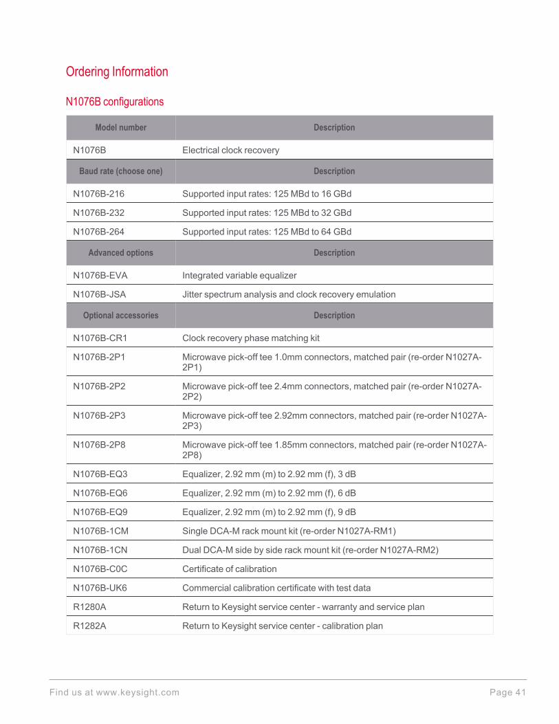
N1076B configurations
Model number Description
N1076B Electrical clock recovery
Baud rate (choose one) Description
N1076B-216 Supported input rates: 125 MBd to 16 GBd
N1076B-232 Supported input rates: 125 MBd to 32 GBd
N1076B-264 Supported input rates: 125 MBd to 64 GBd
Advanced options Description
N1076B-EVA Integrated variable equalizer
N1076B-JSA Jitter spectrum analysis and clock recovery emulation
Optional accessories Description
N1076B-CR1 Clock recovery phase matching kit
N1076B-2P1 Microwave pick-off tee 1.0mm connectors, matched pair (re-order N1027A-2P1)
N1076B-2P2 Microwave pick-off tee 2.4mm connectors, matched pair (re-order N1027A-2P2)
N1076B-2P3 Microwave pick-off tee 2.92mm connectors, matched pair (re-order N1027A-2P3)
N1076B-2P8 Microwave pick-off tee 1.85mm connectors, matched pair (re-order N1027A-2P8)
N1076B-EQ3 Equalizer, 2.92 mm (m) to 2.92 mm (f), 3 dB
N1076B-EQ6 Equalizer, 2.92 mm (m) to 2.92 mm (f), 6 dB
N1076B-EQ9 Equalizer, 2.92 mm (m) to 2.92 mm (f), 9 dB
N1076B-1CM Single DCA-M rack mount kit (re-order N1027A-RM1)
N1076B-1CN Dual DCA-M side by side rack mount kit (re-order N1027A-RM2)
N1076B-C0C Certificate of calibration
N1076B-UK6 Commercial calibration certificate with test data
R1280A Return to Keysight service center - warranty and service plan
R1282A Return to Keysight service center - calibration plan
Find us at www.keysight.com Page 41
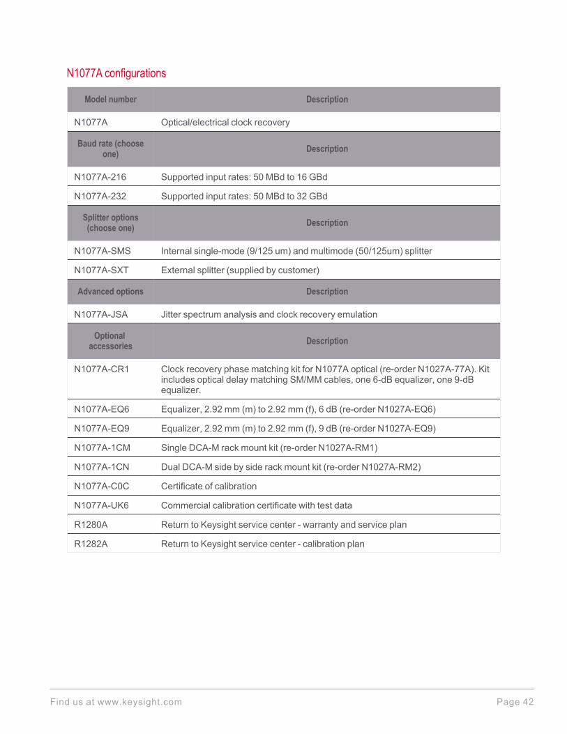
N1077A configurations
Model number Description
N1077A Optical/electrical clock recovery
Baud rate (chooseone) Description
N1077A-216 Supported input rates: 50 MBd to 16 GBd
N1077A-232 Supported input rates: 50 MBd to 32 GBd
Splitter options(choose one) Description
N1077A-SMS Internal single-mode (9/125 um) and multimode (50/125um) splitter
N1077A-SXT External splitter (supplied by customer)
Advanced options Description
N1077A-JSA Jitter spectrum analysis and clock recovery emulation
Optionalaccessories Description
N1077A-CR1 Clock recovery phase matching kit for N1077A optical (re-order N1027A-77A). Kitincludes optical delay matching SM/MM cables, one 6-dB equalizer, one 9-dBequalizer.
N1077A-EQ6 Equalizer, 2.92 mm (m) to 2.92 mm (f), 6 dB (re-order N1027A-EQ6)
N1077A-EQ9 Equalizer, 2.92 mm (m) to 2.92 mm (f), 9 dB (re-order N1027A-EQ9)
N1077A-1CM Single DCA-M rack mount kit (re-order N1027A-RM1)
N1077A-1CN Dual DCA-M side by side rack mount kit (re-order N1027A-RM2)
N1077A-C0C Certificate of calibration
N1077A-UK6 Commercial calibration certificate with test data
R1280A Return to Keysight service center - warranty and service plan
R1282A Return to Keysight service center - calibration plan
Find us at www.keysight.com Page 42
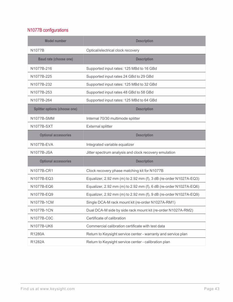
N1077B configurations
Model number Description
N1077B Optical/electrical clock recovery
Baud rate (choose one) Description
N1077B-216 Supported input rates: 125 MBd to 16 GBd
N1077B-225 Supported input rates 24 GBd to 29 GBd
N1077B-232 Supported input rates: 125 MBd to 32 GBd
N1077B-253 Supported input rates 48 GBd to 58 GBd
N1077B-264 Supported input rates: 125 MBd to 64 GBd
Splitter options (choose one) Description
N1077B-SMM Internal 70/30 multimode splitter
N1077B-SXT External splitter
Optional accessories Description
N1077B-EVA Integrated variable equalizer
N1077B-JSA Jitter spectrum analysis and clock recovery emulation
Optional accessories Description
N1077B-CR1 Clock recovery phase matching kit for N1077B
N1077B-EQ3 Equalizer, 2.92 mm (m) to 2.92 mm (f), 3 dB (re-order N1027A-EQ3)
N1077B-EQ6 Equalizer, 2.92 mm (m) to 2.92 mm (f), 6 dB (re-order N1027A-EQ6)
N1077B-EQ9 Equalizer, 2.92 mm (m) to 2.92 mm (f), 9 dB (re-order N1027A-EQ9)
N1077B-1CM Single DCA-M rack mount kit (re-order N1027A-RM1)
N1077B-1CN Dual DCA-M side by side rack mount kit (re-order N1027A-RM2)
N1077B-C0C Certificate of calibration
N1077B-UK6 Commercial calibration certificate with test data
R1280A Return to Keysight service center - warranty and service plan
R1282A Return to Keysight service center - calibration plan
Find us at www.keysight.com Page 43
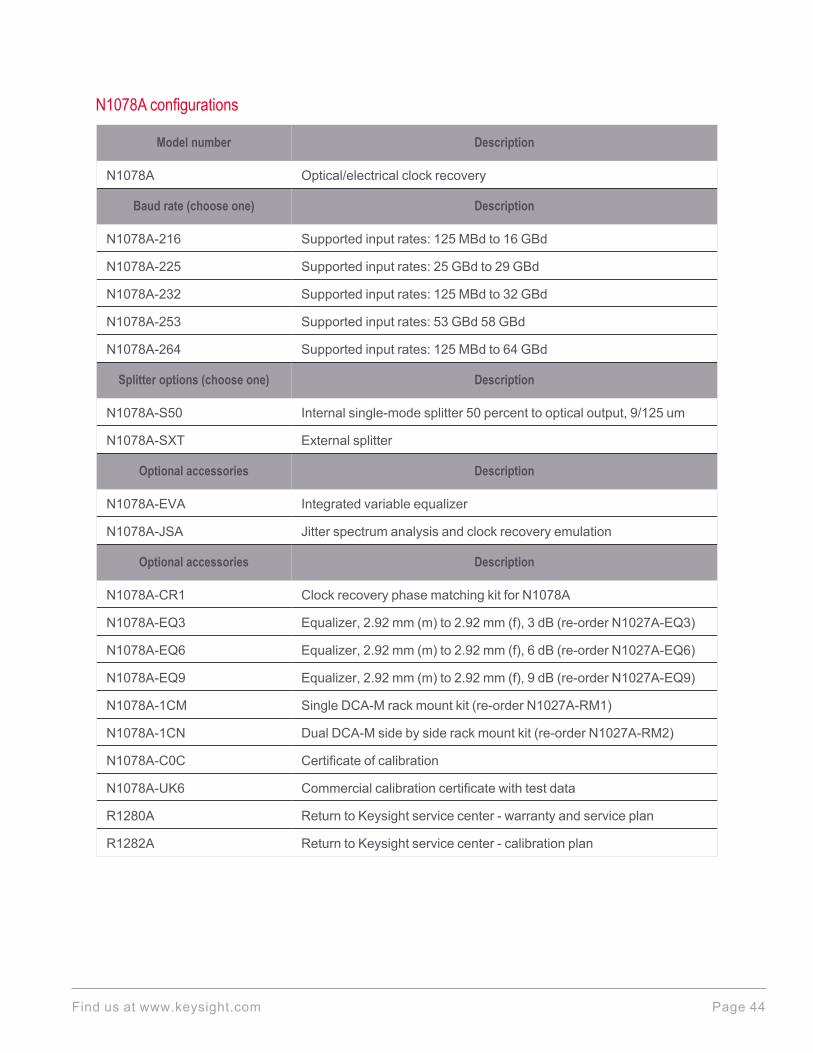
N1078A configurations
Model number Description
N1078A Optical/electrical clock recovery
Baud rate (choose one) Description
N1078A-216 Supported input rates: 125 MBd to 16 GBd
N1078A-225 Supported input rates: 25 GBd to 29 GBd
N1078A-232 Supported input rates: 125 MBd to 32 GBd
N1078A-253 Supported input rates: 53 GBd 58 GBd
N1078A-264 Supported input rates: 125 MBd to 64 GBd
Splitter options (choose one) Description
N1078A-S50 Internal single-mode splitter 50 percent to optical output, 9/125 um
N1078A-SXT External splitter
Optional accessories Description
N1078A-EVA Integrated variable equalizer
N1078A-JSA Jitter spectrum analysis and clock recovery emulation
Optional accessories Description
N1078A-CR1 Clock recovery phase matching kit for N1078A
N1078A-EQ3 Equalizer, 2.92 mm (m) to 2.92 mm (f), 3 dB (re-order N1027A-EQ3)
N1078A-EQ6 Equalizer, 2.92 mm (m) to 2.92 mm (f), 6 dB (re-order N1027A-EQ6)
N1078A-EQ9 Equalizer, 2.92 mm (m) to 2.92 mm (f), 9 dB (re-order N1027A-EQ9)
N1078A-1CM Single DCA-M rack mount kit (re-order N1027A-RM1)
N1078A-1CN Dual DCA-M side by side rack mount kit (re-order N1027A-RM2)
N1078A-C0C Certificate of calibration
N1078A-UK6 Commercial calibration certificate with test data
R1280A Return to Keysight service center - warranty and service plan
R1282A Return to Keysight service center - calibration plan
Find us at www.keysight.com Page 44

N1076/7/8 clock recovery instruments are controlled via a USB connection to a DCA-X mainframe, or to astandalone PC, running N1010A FlexDCA software. The latest version of FlexDCAmay be downloadedfrom: www.keysight.com/find/flexdca_download.
AccessoriesFor accessories, please see the DCA Accessory Guide, pub number 5991-2340EN.
For more information:
l www.keysight.com/find/n1076bl www.keysight.com/find/n1077al www.keysight.com/find/n1077bl www.keysight.com/find/n1078a
Find us at www.keysight.comThis information is subject to change without notice. © Keysight Technologies, 2018 - 2022, Published in USA, February 15, 2022, 5992-1620EN
Learn more at: www.keysight.com
For more information on Keysight Technologies' products, applications or services,please contact your local Keysight office. The complete list is available at:www.keysight.com/find/contactus
Page 45