![- worldtradescanner.comworldtradescanner.com/Annex - Jurisdiction Table.pdf · ñ ' µ µ P u Z À v µ ] ] } ( ' µ µ P u ] v Z } ( , Ç v X](https://static.fdocuments.in/doc/165x107/5a93ba8c7f8b9ad96f8bbe3f/-worldtradescannercomworldtradescannercomannex-jurisdiction-tablepdf-p.jpg)
OPTEL-µ: Optical Terminal for Small Satellite LEO Applications · OPTEL-µ: Optical Terminal for...
15
83230910-DOC-TAS-EN-003 10/11/2016 Ref.: DLR OLEODL Workshop OPTEL-μ: Optical Terminal for Small Satellite LEO Applications Christoph Roth OEI Opto AG
Transcript of OPTEL-µ: Optical Terminal for Small Satellite LEO Applications · OPTEL-µ: Optical Terminal for...

83
23
09
10
-DO
C-T
AS
-EN
-00
3
10/11/2016
Ref.: DLR OLEODL Workshop
OPTEL-µ: Optical Terminal for
Small Satellite LEO Applications
Christoph Roth
OEI Opto AG

2015, Thales Alenia Space
Presentation Outline
System Overview
Communications Subsystem Overview
OPTEL-µ Space Terminal:
Block Diagram
Flight Design
Status of EQM Development
In-Orbit Demonstration
Outlook
10/11/2016
Ref.: DLR OLEODL Workshop
2

2015, Thales Alenia Space
System Overview
Optical downlink to increase mission data
return
Small Sats in LEO Orbit
Modular design of space terminal for various
satellite providers
Developed by OEI Opto AG (former RUAG
Space) under ESA ARTES5.2 / ARTES 3-4
Multiple low-cost ground stations to secure cloud
mitigation
First Flight Model planned for 2017
Small Space Terminal
2x 1Gbps downlink (1550nm)
Low mass, low volume, low power footprint:
8 kg, 8 lt, 43 W
Ground Terminal
0.6 m Ø telescope
Uplink beacon laser
Low-rate uplink service channel (~25kbps)
Laser Safety Class 1M, based on
1064nm LIDAR technology
10/11/2016
Ref.: DLR OLEODL Workshop
3
2015, Thales Alenia Space
Use Cases
10/11/2016
Ref.: DLR OLEODL Workshop
1 2
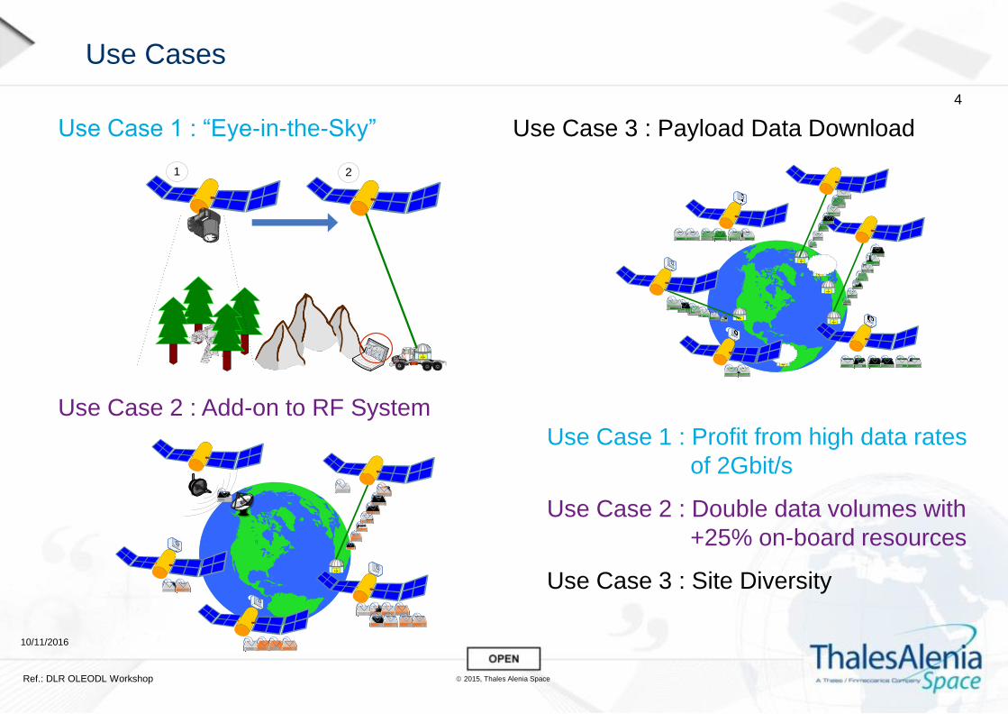
Use Case 1 : “Eye-in-the-Sky” Use Case 3 : Payload Data Download
Use Case 2 : Add-on to RF System
Use Case 1 : Profit from high data rates
of 2Gbit/s
Use Case 2 : Double data volumes with
+25% on-board resources
Use Case 3 : Site Diversity
4

2015, Thales Alenia Space
Communications Subsystem: Overview
A highly robust and flexible
communications scheme is essential
to maximize data volume over
atmospheric channel
OPTEL-µ communications subsystem
can adapt to varying atmospheric
channel conditions relying on three key
features:
10/11/2016
Ref.: DLR OLEODL Workshop
PPM and OOK modulation
OOK maximizes data throughput for good link conditions and short link distance
PPM increases sensitivity and throughput for challenging conditions and long distance
FEC coded transmission
FEC coded transmission with tunable code rates keeps error-rate low and allows for
instantaneous adaptation to varying link conditions
Automatic repeat request (ARQ) protocol
ARQ enables high data throughput with high reliability (e.g. against deep fades)
Can be implemented with very low overhead and latency in space and on ground
5

2015, Thales Alenia Space
Communications Subsystem: User Data Format
10/11/2016
Ref.: DLR OLEODL Workshop
Data transmission is divided into packets
Packets are coded and modulated according to current MCS setting as scheduled
by ground terminal
ARQ feature allows for low-latency re-transmission of lost or corrupt packets
ARQ decisions based on CRC included in packet
6

2015, Thales Alenia Space
Communications Subsystem: Data Rate versus Power Trade-off
10/11/2016
Ref.: DLR OLEODL Workshop
Implemented communications scheme provides wide dynamic range, high
flexibility, and high reliability
7

2015, Thales Alenia Space
OPTEL-µ Space Terminal: Block Diagram
10/11/2016
Ref.: DLR OLEODL Workshop
OPTEL-µ ST
comprises three units:
Optical Head
Laser Unit
Electronics Unit
Benefit of this
modular approach:
Facilitates flexible
integration on the
spacecraft
Distributed thermal /
electrical loads
Optimised for use on
micro-satellites
8

2015, Thales Alenia Space
OPTEL-µ Space Terminal: Optical Head
10/11/2016
Ref.: DLR OLEODL Workshop
Optical Head (OH) comprises:
Micro-Pointing Assembly:
Point towards the Optical Ground Station
Track the received beacon signal
Optical Bench:
Receive beacon signal and relay it onto the
acquisition and tracking sensors (AS and TS)
Collimate the communications laser and beacon
signals (from the Laser Unit)
Route the optical signals to / from the µPA
Implement telescope function (beam expander) as
part of the OB
OH Electronics:
Readout AS and TS, encoder sensors of the µPA
and drive the actuators and motors
Optical Head EQM Design
Optical Head with Back
Cover Removed (Showing
Optical Bench)
9

2015, Thales Alenia Space
OPTEL-µ Space Terminal: Laser Unit
10/11/2016
Ref.: DLR OLEODL Workshop
Laser Unit (LU) comprises:
Pulsed Laser Transmitter:
PLT provides two individually modulated optical channels
each at a raw data rate of 1.25Gbps
Two optical channels are at wavelengths of 1545nm and
1565nm
Optical Fibre Amplifier:
OFA incorporates two individual optical fibre amplifiers that
are optically pumped at 980nm to achieve the required
amplification
Three output signals are generated by the OFA – two
communications signals and the space beacon signal
For each optical channel the output power required from the
OFA is 100mW at end of life.
PLT EQM
OFA EQM
10

2015, Thales Alenia Space
OPTEL-µ Space Terminal: Electronics Unit
10/11/2016
Ref.: DLR OLEODL Workshop
Electronics Unit (EU) comprises:
Power Conditioning Unit (PCU) :
PCU derives from the spacecraft power bus the supply
voltages for the operation of the ST
PCU can operate in a low-power mode (where not all
functionality is required) and the ‘downlink’ mode
Terminal Control Unit (TCU):
Control and operation of the OPTEL-µ ST
Communications subsystem
Telemetry / telecommand (TM/TC) interface
User data interface to the satellite payload. User data is
stored in a Buffer Memory (100GB) prior to a downlink.
RF Modulator (RFM):
RFM serializes the parallel communications data
stream and amplifies the 1.25 Gbps serial stream
which is then used to modulate the seed laser in the
PLT
Electronics Unit EQM Design
Electronics Board Configuration
11

2015, Thales Alenia Space
OPTEL-µ Space Terminal: EQM Development Status
10/11/2016
Ref.: DLR OLEODL Workshop
Optical Head:
µPA – assembly of EQM on-going.
Commissioning tests to be held in Nov. 2016.
Optical Bench – qualification tests completed.
Delivery end Sept. 2016.
Optical Head Electronics – manufacture of the
OHE EQM electronics on-going
Laser Unit:
Pulsed Laser Transmitter – integration
completed and performance tests on-going
Optical Fibre Amplifier – integration of the OFA
EQM on-going
Electronics Unit:
Power Conditioning Unit – performance tests
on-going. Delivery planned for Nov. 2016.
Terminal Control Unit – manufacture of the
TCU EQM on-going
RF Modulator – manufacture of the TCU EQM
on-going
Optical Bench EQM µPA EQM
PLT EQM OFA EQM
Electronics Unit EM+
12
2015, Thales Alenia Space
In-Orbit Demonstration Opportunity
10/11/2016
Ref.: DLR OLEODL Workshop
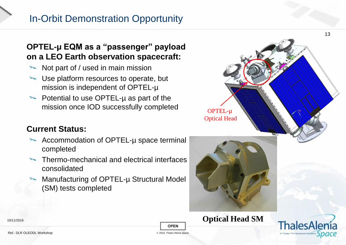
OPTEL-µ EQM as a “passenger” payload
on a LEO Earth observation spacecraft:
Not part of / used in main mission
Use platform resources to operate, but
mission is independent of OPTEL-µ
Potential to use OPTEL-µ as part of the
mission once IOD successfully completed
Current Status:
Accommodation of OPTEL-µ space terminal
completed
Thermo-mechanical and electrical interfaces
consolidated
Manufacturing of OPTEL-µ Structural Model
(SM) tests completed
Optical Head SM
OPTEL-µ
Optical Head
13

2015, Thales Alenia Space
Outlook
10/11/2016
Ref.: DLR OLEODL Workshop
EQM development timeline:
Environmental Tests = Feb. – Apr. 2017
System Tests = May 2017
Shipment to S/C for IOD = June 2017
IOD timeline:
S/C AIT = H2 2017
Launch = Jan. 2018 (TBC)
IOD in 2018 – 12 month duration
Commercialisation of the OPTEL-µ product:
Discussions on-going with a number of satellite operators / Earth Observation users
interested to procure and use OPTEL-µ in their system
14

2015, Thales Alenia Space
Acknowledgements
10/11/2016
Ref.: DLR OLEODL Workshop
Development of the OPTEL-µ optical terminal is being funded jointly by ESA and OEI Opto
AG under the ARTES programme. The authors would like to express our gratitude to Paul
van Loock and Dr. Zoran Sodnik at ESTEC, together with the Swiss Space Office and
national delegations of all subcontractors for their continued support in the execution of this
work.
In addition, we gratefully acknowledge the contributions and support from our partners and
subcontractors involved in the OPTEL-µ development – these being:
Deimos (UK) for supporting on S/C accommodation and mission scenarios,
Gooch & Housego (UK) for the design and development of the Optical Fibre Amplifier,
LusoSpace (Portugal) for the design and development of the Pulsed Laser Transmitter,
RUAG Space (Finland) for the design and development of the Power Conditioning Unit,
SES Techcom (Luxembourg) for supporting on the Optical Ground Station Integration,
SSC (Sweden) for Ground Network Analysis,
TNO and Nedinsco (The Netherlands) and Meopta (Czech Republic) for the design and
development of the Optical Bench.
15


![6XEMHFW INFORMATION µ µ } ( D } } o } P Ç · 2020. 1. 8. · ] v D v P P ] µ o µ µ ] v ^ } o µ ] } v INFORMATION µ µ } ( D } } o } P Ç FOI30/6146 Exempt material has been](https://static.fdocuments.in/doc/165x107/605669a2db3e6636e335f900/6xemhfw-information-d-o-p-2020-1-8-v-d-v-p-p-o-.jpg)
![} v } µ µ Æ ( µ o D ] v W Z u ] µ Æ & µ o D ] v v ] î ì î ...](https://static.fdocuments.in/doc/165x107/62ab993ab1f3af1e1743d946/-v-o-d-v-w-z-u-amp.jpg)


![BKM INDUSTRIES LIMITED€¦ · 13. dZ }u vÇ] }v v }µ Z vÀ] }vu v v µ o]Ì v µ o }µ ]v µ ]v o ÁÇXt µ Ç}µ } µ Ç}µ u]o Á] ZÇ}µ } ] } ÇW ] v } v o µ } v Ç}µ Z vvµoZ](https://static.fdocuments.in/doc/165x107/5f7aa2ab21740547403de5fd/bkm-industries-limited-13-dz-u-v-v-v-z-v-vu-v-v-ooe-v-o-.jpg)
![9HJDQ 0HQX - The Pie Pizzeria7kh 3lh·v yhuvlrq ri d &do]rqh µ µ µ 35,&( 3(5 9(**,( 7233,1* µ µ µ](https://static.fdocuments.in/doc/165x107/5e6b901b2755ca704e2e3262/9hjdq-0hqx-the-pie-pizzeria-7kh-3lhv-yhuvlrq-ri-d-dorqh-35.jpg)

![SENSACIà N, PERCEPCIà N Y RAZONAMIENTOS€¦ · ï µ o µ W ] v µ o µ o µ v o µ À ] À µ v ] v ] À ] µ } } v ] µ Ç ^ µ _ µ](https://static.fdocuments.in/doc/165x107/6032fd624538023875270df3/sensacif-n-percepcif-n-y-razonamientos-o-w-v-o-o-v-o-.jpg)


![2020 Licensed Contractors - Gary › wp-content › uploads › 2020 › 04 › 2020_Licensed_C… · µ ] v E u µ ] v ^ µ ] v ] Ç r ^ µ ] v ] µ ] v W Z } v / µ d } E u / µ](https://static.fdocuments.in/doc/165x107/5f1b8c5fa029b824796b3b45/2020-licensed-contractors-gary-a-wp-content-a-uploads-a-2020-a-04-a.jpg)


![v µ ] } v ( } ^ µ v u o } Ç u v Z µ & } u ] v ^ u µ Ç W o µ d Z ^ µ v u o ... · 2020. 4. 22. · P v v u ] o } Ç } µ Z } µ P Z ^ u µ Ç W o µ X d Z µ v v v } P ]](https://static.fdocuments.in/doc/165x107/604f2238d9677b2b16176feb/v-v-v-u-o-u-v-z-u-v-u-w-o-d-z-.jpg)