OPI-3601master spec - Streckkod OPI-3601...Document History Model Number: OPI-3601 Specification...
45
2D Imager Scanner OPI-3601 This manual provides specifications for the OPI-3601 handheld 2D imager scanner. Specifications Manual
Transcript of OPI-3601master spec - Streckkod OPI-3601...Document History Model Number: OPI-3601 Specification...
2D Imager Scanner
OPI-3601
This manual provides specifications for the OPI-3601 handheld 2D imager scanner. Specifications Manual

OPI-3601 Specifications Manual
All information subject to change without notice.
Document History Model Number: OPI-3601 Specification Number: SS12016
Edition: 1st Original Spec Number: SS12015
Date: 2012-09-21
Copyright 2010 Opticon. All rights reserved. This manual may not, in whole or in part, be copied, photocopied, reproduced, translated or converted to any electronic or machine readable form without prior written consent of Opticon.
Limited Warranty and Disclaimers PLEASE READ THIS MANUAL CAREFULLY BEFORE INSTALLING OR USING THE PRODUCT.
Serial Number A serial number appears on all Opticon products. This official registration number is directly related to the device purchased. Do not remove the serial number from your Opticon device. Removing the serial number voids the warranty.
Warranty Unless otherwise agreed in a written contract, all Opticon products are warranted against defects in materials and workmanship for two years after purchase. Opticon will repair or, at its option, replace products that are defective in materials or workmanship with proper use during the warranty period. Opticon is not liable for damages caused by modifications made by a customer. In such cases, standard repair charges will apply. If a product is returned under warranty and no defect is found, standard repair charges will apply. Opticon assumes no liability for any direct, indirect, consequential or incidental damages arising out of use or inability to use both the hardware and software, even if Opticon has been informed about the possibility of such damages.
Packaging The packing materials are recyclable. We recommend that you save all packing material to use should you need to transport your scanner or send it for service. Damage caused by improper packaging during shipment is not covered by the warranty.
Trademarks Trademarks used are the property of their respective owners.
Opticon Inc. and Opticon Sensors Europe B.V. are wholly owned subsidiaries of OPTOELECTRONICS Co., Ltd., 12-17, Tsukagoshi 4-chome, Warabi-shi, Saitama, Japan 335-0002. TEL +81-(0) 48-446-1183; FAX +81-(0) 48-446-1184
SUPPORT USA Europe
Phone: 800-636-0090
Email: [email protected] Email: [email protected]
Web: www.opticonusa.com Web: www.opticon.com

OPI-3601 Specifications Manual
Revision History
Specification No. : SS12016 Product name : OPI-3601
Edition Date Page Section Description of Changes
First 2012/09/21 - - Initial release
OPI-3601 Specifications Manual
Contents 1. Abstract........................................................................................................................................1 2. Overview ......................................................................................................................................1 3. Basic Specifications ...................................................................................................................2 4. Detailed View ...............................................................................................................................5 5. Electrical Specifications .............................................................................................................6
5.1. AC Adapter Specifications ...................................................................................................6 5.1.1. Input Specifications ................................................................................................................... 6 5.1.2. Output Specifications ................................................................................................................ 6
5.2. Wedge PS/2 Power Supply (Host) .......................................................................................6 5.3. USB Power Supply ..............................................................................................................6
6. Optical Specifications.................................................................................................................7 6.1. Basic Optical Specifications.................................................................................................7 6.2. Aiming Pattern .....................................................................................................................8 6.3. Imaging Range.....................................................................................................................8
7. Technical Specifications ............................................................................................................9 7.1. Barcode Test Sample ........................................................................................................10 7.2. Scan Area and Depth of Field............................................................................................11 7.3. Printed Contrast Signal (PCS) ...........................................................................................12 7.4. Minimum Resolution ..........................................................................................................12 7.5. Wide Bar Code...................................................................................................................12 7.6. Pitch, Skew and Tilt ...........................................................................................................13 7.7. Curvature ...........................................................................................................................13 7.8. Auto Trigger .......................................................................................................................14
7.8.1. Stand Detection ....................................................................................................................... 14 7.8.2. Auto Trigger Detection ............................................................................................................ 15 7.8.3. Motion Tolerance..................................................................................................................... 15
8. Interface Specifications ............................................................................................................16 8.1. RS-232C ............................................................................................................................16
8.1.1. Communication Setting ........................................................................................................... 16 8.1.2. Signal Level and Pin Assignment............................................................................................ 16 8.1.3. RS-232C Interface Circuit ....................................................................................................... 17
8.2. USB....................................................................................................................................18 8.2.1. USB Interface Specifications................................................................................................... 18 8.2.2. Connector ................................................................................................................................ 18 8.2.3. USB Interface Circuit ............................................................................................................... 18
8.3. Wedge PS/2.......................................................................................................................19
OPI-3601 Specifications Manual
8.3.1. How to Connect ....................................................................................................................... 19 8.3.2. Caution .................................................................................................................................... 19 8.3.3. Pin Assignment........................................................................................................................ 20
9. Cable and Connector ................................................................................................................21 9.1. RS-232C ............................................................................................................................21 9.2. USB....................................................................................................................................21 9.3. Wedge PS/2.......................................................................................................................22
9.3.1. Wedge PS/2 Straight Cable .................................................................................................... 22 9.3.2. Wedge PS/2 Branch Cable ..................................................................................................... 22
10. Environmental Specifications ..................................................................................................23 10.1. Temperature ......................................................................................................................23 10.2. Humidity .............................................................................................................................23 10.3. Ambient Light Immunity .....................................................................................................24 10.4. Dust and Drip Proof ...........................................................................................................24 10.5. Cable Strength ...................................................................................................................25 10.6. Cable Bending Strength.....................................................................................................25 10.7. Vibration Strength (without packing) ..................................................................................25 10.8. Vibration Strength (in individual packing)...........................................................................25 10.9. Drop Impact Strength (without packaging).........................................................................26 10.10. Drop Impact Strength (in individual packaging) .........................................................26 10.11. Electrical Specifications .............................................................................................26
11. Default Setting ...........................................................................................................................27 11.1. Default Setting Menu Code................................................................................................27 11.2. Supported Symbologies.....................................................................................................27
11.2.1. 1D bar codes ........................................................................................................................... 27 11.2.2. GS1 Databar, Composite Code............................................................................................... 28 11.2.3. 2D Codes................................................................................................................................. 28
11.3. Other Default......................................................................................................................29 11.4. RS-232C Default ................................................................................................................29 11.5. USB-COM ..........................................................................................................................30 11.6. USB-HID, Wedge PS/2 Defaults ........................................................................................30
12. Regulatory Compliance ............................................................................................................31 12.1. LED Safety.........................................................................................................................31 12.2. EMC ...................................................................................................................................31
13. RoHS...........................................................................................................................................31 14. Reliability ...................................................................................................................................31 15. Precautions................................................................................................................................31
OPI-3601 Specifications Manual
16. Product Labels ..........................................................................................................................32 17. Packaging Specifications .........................................................................................................33
17.1. Individual Packaging (RS-232C/Wedge PS/2)...................................................................33 17.2. Collective Packaging (RS-232C/Wedge) ...........................................................................34 17.3. Individual Packaging (USB) ...............................................................................................35 17.4. Collective Packaging (USB)...............................................................................................36
18. Physical Features......................................................................................................................37 18.1. Dimensions ........................................................................................................................37 18.2. Weight................................................................................................................................37 18.3. Mechanical Drawing...........................................................................................................37
19. Accessories ...............................................................................................................................38 19.1. AC Adapter Specifications .................................................................................................38 19.2. AC Adapter Mechanical Drawing .......................................................................................38
20. STD-3601 Stand (Sold Separately)...........................................................................................39 20.1. Stand Mechanical Drawing ................................................................................................39
OPI-3601 Specifications Manual
1
1. Abstract This manual provides specifications for the OPI-3601 handheld 2D imager scanner. 2. Overview The OPI-3601 is a handheld 2D imager scanner that enables high speed scanning of standard linear (1D) and 2D symbologies. Main features of the OPI-3601 are as follows:
・High-speed scanning
Extremely high speed performance ensures stress free scanning and fast response without being affected by hand movement and light conditions.
・Auto trigger, moving object scanning
With the use of a dedicated stand, the scanner is automatically triggered and a moving target can be detected automatically and scanned instantaneously.
・Editing function A new function “Data Editing Program” captures up to 16 codes on multiple images simultaneously in one go. Output editing process, such as GS1 format, also can be set easily.
・World's most compact 2D scanner in its class The OPI-3601 offers ultra-compact size and easy operation.
・LED aiming A sharp single line of green LED makes it easy to aim the scanner while providing safety and long-life.
・Antimicrobial coating Special antimicrobial treatment is applied to the chassis, and alcohol can be used to clean the scanner (except for the scanning window and the logo panel).
・Various interfaces Four types of interfaces, RS-232C, Keyboard Wedge PS/2, USB-HID, and USB-COM, are supported.
・RoHS compliance The OPI-3601 is a RoHS compliant product, which is declared by Optoelectronics Co., Ltd.
* Refer to “OPI-3601 User’s Manual” for supported codes and commands.
OPI-3601 Specifications Manual
2
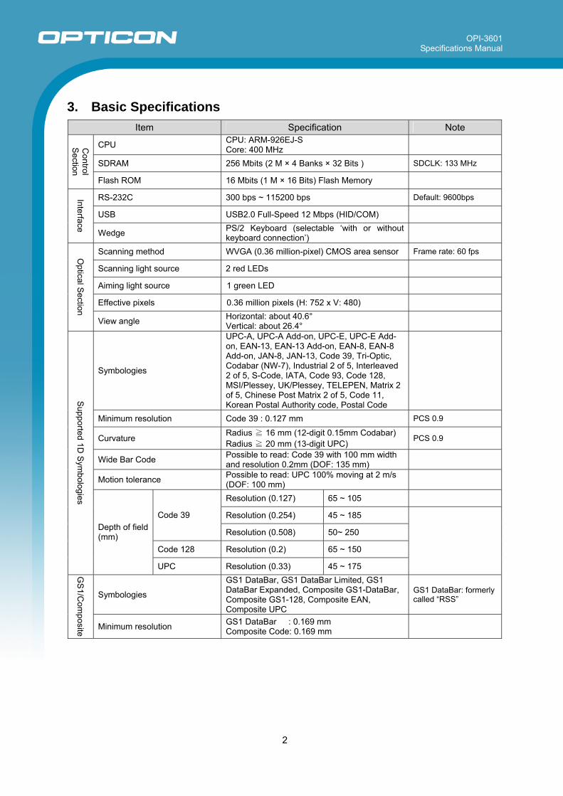
3. Basic Specifications
Item Specification Note
CPU CPU: ARM-926EJ-S Core: 400 MHz
SDRAM 256 Mbits (2 M × 4 Banks × 32 Bits ) SDCLK: 133 MHz
Control
Section
Flash ROM 16 Mbits (1 M × 16 Bits) Flash Memory
RS-232C 300 bps ~ 115200 bps Default: 9600bps
USB USB2.0 Full-Speed 12 Mbps (HID/COM)
Interface Wedge PS/2 Keyboard (selectable ‘with or without keyboard connection’)
Scanning method WVGA (0.36 million-pixel) CMOS area sensor Frame rate: 60 fps
Scanning light source 2 red LEDs
Aiming light source 1 green LED
Effective pixels 0.36 million pixels (H: 752 x V: 480)
Optical S
ection
View angle Horizontal: about 40.6° Vertical: about 26.4°
Symbologies
UPC-A, UPC-A Add-on, UPC-E, UPC-E Add-on, EAN-13, EAN-13 Add-on, EAN-8, EAN-8 Add-on, JAN-8, JAN-13, Code 39, Tri-Optic, Codabar (NW-7), Industrial 2 of 5, Interleaved 2 of 5, S-Code, IATA, Code 93, Code 128, MSI/Plessey, UK/Plessey, TELEPEN, Matrix 2 of 5, Chinese Post Matrix 2 of 5, Code 11, Korean Postal Authority code, Postal Code
Minimum resolution Code 39 : 0.127 mm PCS 0.9
Curvature Radius ≧ 16 mm (12-digit 0.15mm Codabar) Radius ≧ 20 mm (13-digit UPC)
PCS 0.9
Wide Bar Code Possible to read: Code 39 with 100 mm width and resolution 0.2mm (DOF: 135 mm)
Motion tolerance Possible to read: UPC 100% moving at 2 m/s (DOF: 100 mm)
Resolution (0.127) 65 ~ 105
Resolution (0.254) 45 ~ 185 Code 39
Resolution (0.508) 50~ 250
Code 128 Resolution (0.2) 65 ~ 150
Supported 1D Sym
bologies
Depth of field (mm)
UPC Resolution (0.33) 45 ~ 175
Symbologies
GS1 DataBar, GS1 DataBar Limited, GS1 DataBar Expanded, Composite GS1-DataBar, Composite GS1-128, Composite EAN, Composite UPC
GS1 DataBar: formerly called “RSS”
GS
1/Com
posite
Minimum resolution GS1 DataBar : 0.169 mm Composite Code: 0.169 mm
OPI-3601 Specifications Manual
3
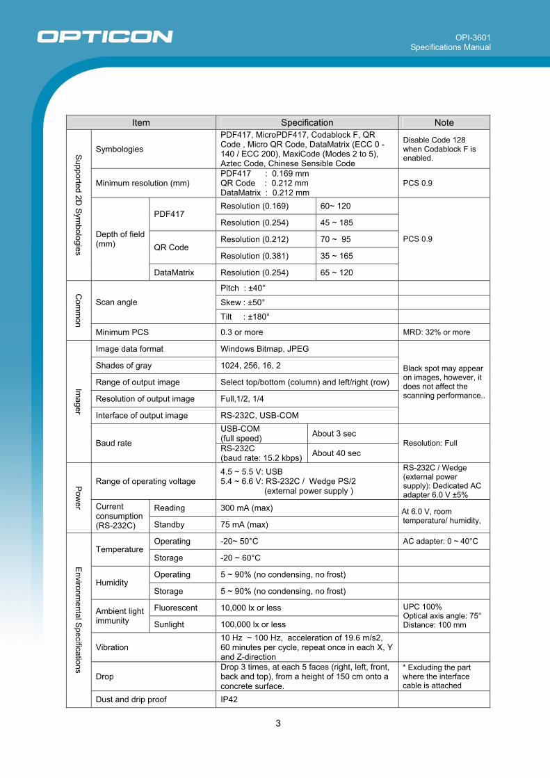
Item Specification Note
Symbologies
PDF417, MicroPDF417, Codablock F, QR Code , Micro QR Code, DataMatrix (ECC 0 - 140 / ECC 200), MaxiCode (Modes 2 to 5), Aztec Code, Chinese Sensible Code
Disable Code 128 when Codablock F is enabled.
Minimum resolution (mm) PDF417 : 0.169 mm QR Code : 0.212 mm DataMatrix : 0.212 mm
PCS 0.9
Resolution (0.169) 60~ 120 PDF417
Resolution (0.254) 45 ~ 185
Resolution (0.212) 70 ~ 95 QR Code
Resolution (0.381) 35 ~ 165
Supported 2D Sym
bologies
Depth of field (mm)
DataMatrix Resolution (0.254) 65 ~ 120
PCS 0.9
Pitch : ±40°
Skew : ±50° Scan angle
Tilt : ±180°
Com
mon
Minimum PCS 0.3 or more MRD: 32% or more
Image data format Windows Bitmap, JPEG
Shades of gray 1024, 256, 16, 2
Range of output image Select top/bottom (column) and left/right (row)
Resolution of output image Full,1/2, 1/4
Interface of output image RS-232C, USB-COM
Black spot may appear on images, however, it does not affect the scanning performance..
USB-COM (full speed) About 3 sec
Imager
Baud rate RS-232C (baud rate: 15.2 kbps) About 40 sec
Resolution: Full
Range of operating voltage 4.5 ~ 5.5 V: USB 5.4 ~ 6.6 V: RS-232C / Wedge PS/2
(external power supply )
RS-232C / Wedge (external power supply): Dedicated AC adapter 6.0 V ±5%
Reading 300 mA (max)
Pow
er Current consumption (RS-232C) Standby 75 mA (max)
At 6.0 V, room temperature/ humidity,
Operating -20~ 50°C AC adapter: 0 ~ 40°C Temperature
Storage -20 ~ 60°C
Operating 5 ~ 90% (no condensing, no frost) Humidity
Storage 5 ~ 90% (no condensing, no frost)
Fluorescent 10,000 lx or less Ambient light immunity Sunlight 100,000 lx or less
UPC 100% Optical axis angle: 75° Distance: 100 mm
Vibration 10 Hz ~ 100 Hz, acceleration of 19.6 m/s2, 60 minutes per cycle, repeat once in each X, Y and Z-direction
Drop Drop 3 times, at each 5 faces (right, left, front, back and top), from a height of 150 cm onto a concrete surface.
* Excluding the part where the interface cable is attached
Environm
ental Specifications
Dust and drip proof IP42
OPI-3601 Specifications Manual
4
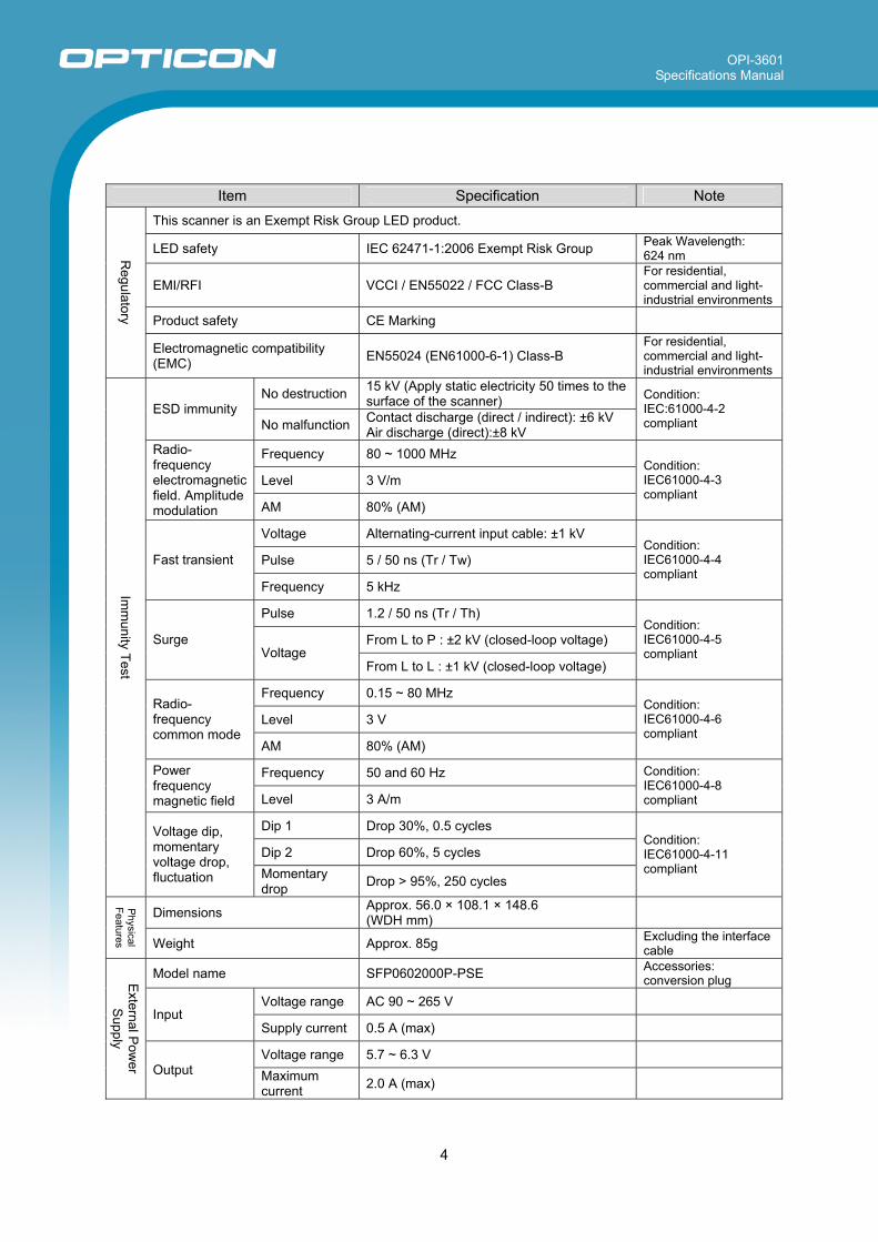
Item Specification Note
This scanner is an Exempt Risk Group LED product.
LED safety IEC 62471-1:2006 Exempt Risk Group Peak Wavelength: 624 nm
EMI/RFI VCCI / EN55022 / FCC Class-B For residential, commercial and light-industrial environments
Product safety CE Marking
Regulatory
Electromagnetic compatibility (EMC) EN55024 (EN61000-6-1) Class-B
For residential, commercial and light-industrial environments
No destruction 15 kV (Apply static electricity 50 times to the surface of the scanner) ESD immunity
No malfunction Contact discharge (direct / indirect): ±6 kV Air discharge (direct):±8 kV
Condition: IEC:61000-4-2 compliant
Frequency 80 ~ 1000 MHz
Level 3 V/m
Radio-frequency electromagnetic field. Amplitude modulation AM 80% (AM)
Condition: IEC61000-4-3 compliant
Voltage Alternating-current input cable: ±1 kV
Pulse 5 / 50 ns (Tr / Tw) Fast transient
Frequency 5 kHz
Condition: IEC61000-4-4 compliant
Pulse 1.2 / 50 ns (Tr / Th)
From L to P : ±2 kV (closed-loop voltage) Surge Voltage
From L to L : ±1 kV (closed-loop voltage)
Condition: IEC61000-4-5 compliant
Frequency 0.15 ~ 80 MHz
Level 3 V Radio-frequency common mode
AM 80% (AM)
Condition: IEC61000-4-6 compliant
Frequency 50 and 60 Hz Power frequency magnetic field Level 3 A/m
Condition: IEC61000-4-8 compliant
Dip 1 Drop 30%, 0.5 cycles
Dip 2 Drop 60%, 5 cycles
Imm
unity Test
Voltage dip, momentary voltage drop, fluctuation Momentary
drop Drop > 95%, 250 cycles
Condition: IEC61000-4-11 compliant
Dimensions Approx. 56.0 × 108.1 × 148.6 (WDH mm)
Physical
Features Weight Approx. 85g Excluding the interface cable
Model name SFP0602000P-PSE Accessories: conversion plug
Voltage range AC 90 ~ 265 V Input
Supply current 0.5 A (max)
Voltage range 5.7 ~ 6.3 V
External P
ower
Supply
Output Maximum current 2.0 A (max)
OPI-3601 Specifications Manual
5
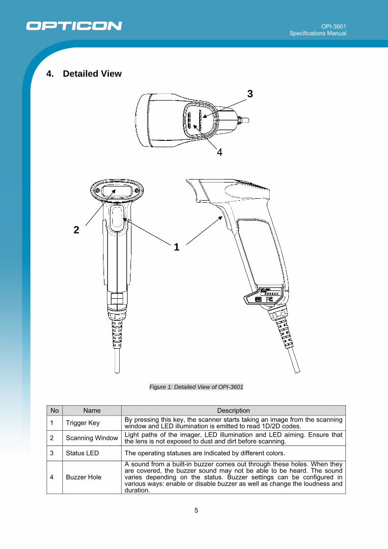
4. Detailed View
Figure 1: Detailed View of OPI-3601
No Name Description
1 Trigger Key By pressing this key, the scanner starts taking an image from the scanning window and LED illumination is emitted to read 1D/2D codes.
2 Scanning Window Light paths of the imager, LED illumination and LED aiming. Ensure that the lens is not exposed to dust and dirt before scanning.
3 Status LED The operating statuses are indicated by different colors.
4 Buzzer Hole
A sound from a built-in buzzer comes out through these holes. When they are covered, the buzzer sound may not be able to be heard. The sound varies depending on the status. Buzzer settings can be configured in various ways: enable or disable buzzer as well as change the loudness and duration.
1 2
3
4
OPI-3601 Specifications Manual
6
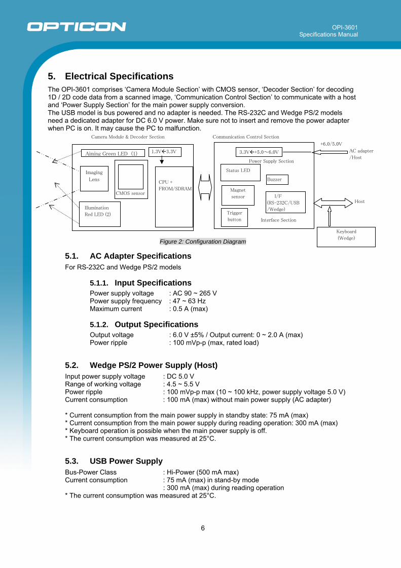
5. Electrical Specifications The OPI-3601 comprises ‘Camera Module Section’ with CMOS sensor, ‘Decoder Section’ for decoding 1D / 2D code data from a scanned image, ‘Communication Control Section’ to communicate with a host and ‘Power Supply Section’ for the main power supply conversion. The USB model is bus powered and no adapter is needed. The RS-232C and Wedge PS/2 models need a dedicated adapter for DC 6.0 V power. Make sure not to insert and remove the power adapter when PC is on. It may cause the PC to malfunction.
Figure 2: Configuration Diagram
5.1. AC Adapter Specifications For RS-232C and Wedge PS/2 models
5.1.1. Input Specifications Power supply voltage : AC 90 ~ 265 V Power supply frequency : 47 ~ 63 Hz Maximum current : 0.5 A (max)
5.1.2. Output Specifications Output voltage : 6.0 V ±5% / Output current: 0 ~ 2.0 A (max) Power ripple : 100 mVp-p (max, rated load)
5.2. Wedge PS/2 Power Supply (Host) Input power supply voltage : DC 5.0 V Range of working voltage : 4.5 ~ 5.5 V Power ripple : 100 mVp-p max (10 ~ 100 kHz, power supply voltage 5.0 V) Current consumption : 100 mA (max) without main power supply (AC adapter) * Current consumption from the main power supply in standby state: 75 mA (max) * Current consumption from the main power supply during reading operation: 300 mA (max) * Keyboard operation is possible when the main power supply is off. * The current consumption was measured at 25°C.
5.3. USB Power Supply Bus-Power Class : Hi-Power (500 mA max) Current consumption : 75 mA (max) in stand-by mode : 300 mA (max) during reading operation * The current consumption was measured at 25°C.
Power Supply Section
Camera Module & Decoder Section
CMOS sensor
Host
CPU +
FROM/SDRAM
3.3V +5.0~6.0V
I/F
(RS-232C/USB
/Wedge)
Buzzer
+6.0/5.0V
AC adapter
/Host
Status LED
Illumination
Red LED (2)
Keyboard
(Wedge)
Imaging
Lens
1.3V 3.3V
Trigger
button
Magnet
sensor
Interface Section
Aiming Green LED (1)
Communication Control Section
OPI-3601 Specifications Manual
7
6. Optical Specifications
6.1. Basic Optical Specifications Item Characteristics
Scan method CMOS area sensor (white / black) -
Number of effective pixel (Column) × (Row) 752 × 480 dots
Image capture speed (*1) Frame rate 60 fps
Focal distance Distance from the front edge of scanner 104 mm
Horizontal Approx. 40.6° View angle
Vertical Approx. 26.4°
Red LED -
Peak wavelength 617 nm
Directivity angle: 2Φ 1/2 (*2) 60° Illumination light source (LED × 2)
Maximum radiation output (*3) 15000 mcd
Green LED -
Peak wavelength 528 nm Aiming light source
Maximum radiation output (*4) 18700 mcd *1 The fastest seed of image capture *2 Reference value extracted from the datasheet. *3, *4 Reference value based on the datasheet (25°C, IF = 140 mA ).
OPI-3601 Specifications Manual
8
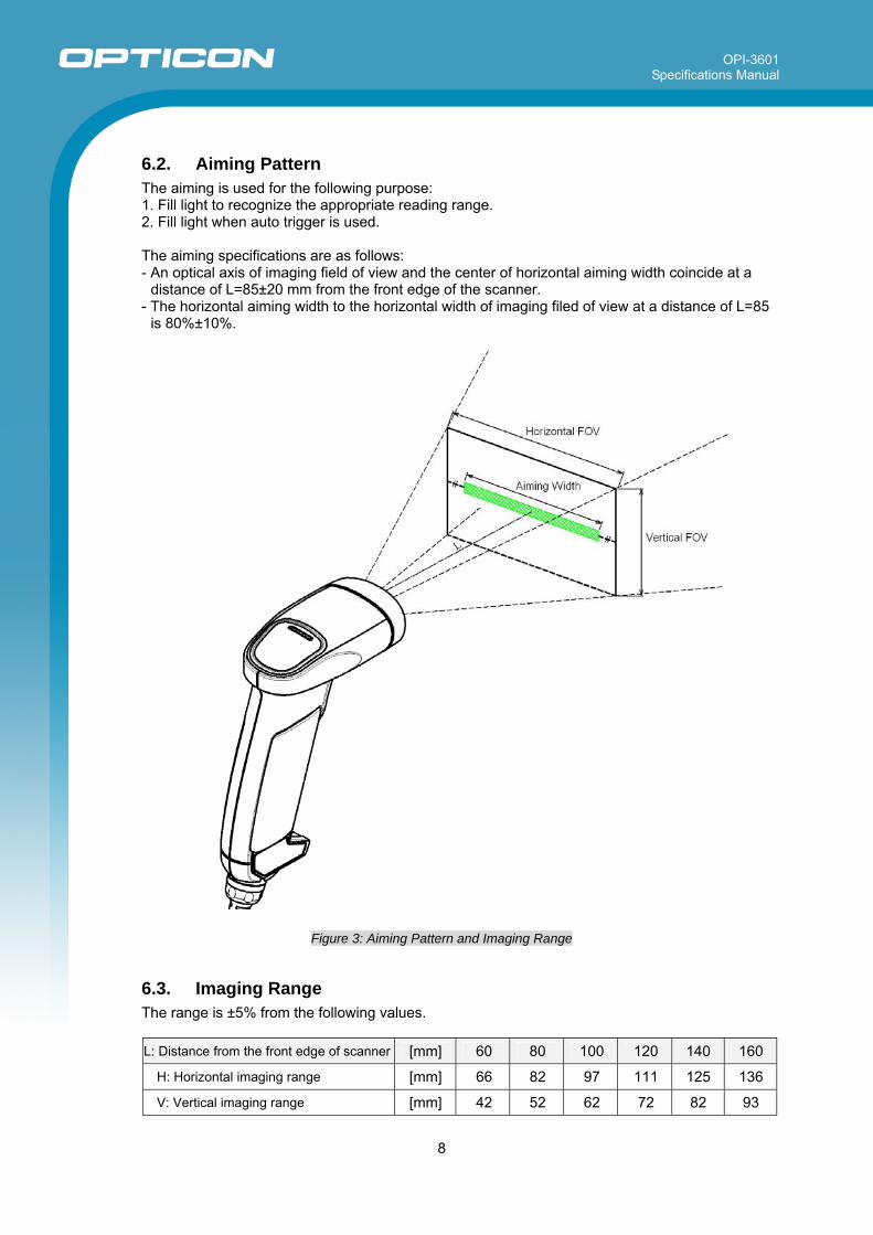
6.2. Aiming Pattern The aiming is used for the following purpose: 1. Fill light to recognize the appropriate reading range. 2. Fill light when auto trigger is used. The aiming specifications are as follows: - An optical axis of imaging field of view and the center of horizontal aiming width coincide at a
distance of L=85±20 mm from the front edge of the scanner. - The horizontal aiming width to the horizontal width of imaging filed of view at a distance of L=85
is 80%±10%.
Figure 3: Aiming Pattern and Imaging Range
6.3. Imaging Range The range is ±5% from the following values. L: Distance from the front edge of scanner [mm] 60 80 100 120 140 160
H: Horizontal imaging range [mm] 66 82 97 111 125 136
V: Vertical imaging range [mm] 42 52 62 72 82 93
OPI-3601 Specifications Manual
9
7. Technical Specifications Aim the laser light at the center of a code to scan it. For long distance scanning, ambient light entering the angle of view may affect the scanning performance. The conditions for technical specifications are as follows, unless otherwise specified in each section.
<Conditions> Ambient Temperature and Humidity Room temperature, room humidity Ambient Light 100 ~200 lux (on the surface of a bar code) Angles Pitch: α = 0°, Skew: β = 15°, Tilt: γ = 0° Curvature R = ∞ Power Supply Voltage 5.0 V PCS (1D and 2D) 0.9 or higher Scanning Test Accept the performance with 70% or more success rate
for 10 tries of scan. One reading should be 2 seconds. Barcode Test Sample (1D and 2D) Specified below.
< Test chart > For 1D codes, OPTOELECTRONICS test samples For GS1 Databar, stacked codes and 2D codes, printed by a dedicated printer for bar code
OPI-3601 Specifications Manual
10
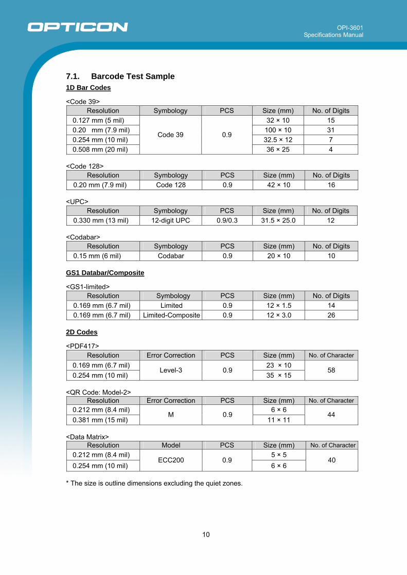
7.1. Barcode Test Sample 1D Bar Codes
<Code 39>
Resolution Symbology PCS Size (mm) No. of Digits 0.127 mm (5 mil) 32 × 10 15 0.20 mm (7.9 mil) 100 × 10 31 0.254 mm (10 mil) 32.5 × 12 7 0.508 mm (20 mil)
Code 39 0.9
36 × 25 4
<Code 128> Resolution Symbology PCS Size (mm) No. of Digits
0.20 mm (7.9 mil) Code 128 0.9 42 × 10 16
<UPC> Resolution Symbology PCS Size (mm) No. of Digits
0.330 mm (13 mil) 12-digit UPC 0.9/0.3 31.5 × 25.0 12
<Codabar> Resolution Symbology PCS Size (mm) No. of Digits
0.15 mm (6 mil) Codabar 0.9 20 × 10 10
GS1 Databar/Composite <GS1-limited>
Resolution Symbology PCS Size (mm) No. of Digits 0.169 mm (6.7 mil) Limited 0.9 12 × 1.5 14 0.169 mm (6.7 mil) Limited-Composite 0.9 12 × 3.0 26
2D Codes
<PDF417>
Resolution Error Correction PCS Size (mm) No. of Character
0.169 mm (6.7 mil) 23 × 10 0.254 mm (10 mil)
Level-3 0.9 35 × 15
58
<QR Code: Model-2>
Resolution Error Correction PCS Size (mm) No. of Character0.212 mm (8.4 mil) 6 × 6 0.381 mm (15 mil)
M 0.9 11 × 11
44
<Data Matrix>
Resolution Model PCS Size (mm) No. of Character0.212 mm (8.4 mil) 5 × 5 0.254 mm (10 mil)
ECC200 0.9 6 × 6
40
* The size is outline dimensions excluding the quiet zones.
OPI-3601 Specifications Manual
11
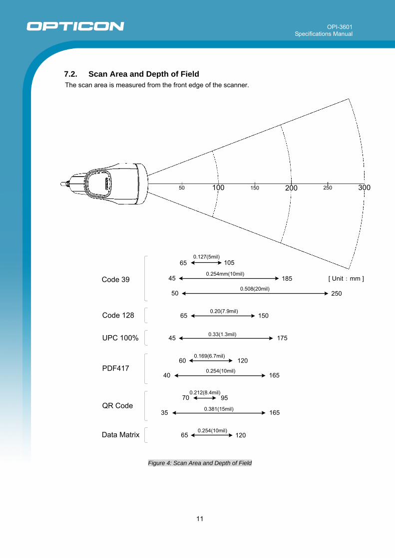
7.2. Scan Area and Depth of Field The scan area is measured from the front edge of the scanner.
250
65 150
175
12060
16540
70 95
35 165
65 120
Code 128
UPC 100%
PDF417
QR Code
Data Matrix
0.508(20mil)
0.20(7.9mil)
0.33(1.3mil)
0.169(6.7mil)
0.254(10mil)
0.212(8.4mil)
0.381(15mil)
0.254(10mil)
45
50
50 100 150 200 250 300
0.127(5mil)65 105
45 185 [ Unit : mm ]0.254mm(10mil)
Code 39
Figure 4: Scan Area and Depth of Field
OPI-3601 Specifications Manual
12
7.3. Printed Contrast Signal (PCS) 0.3 or higher
<Conditions> MRD : 32% and higher
(70% or higher reflectivity of space and quiet zone) Distance : 105mm from the front edge of the scanner Bar Code Sample : UPC specified in Chapter 8. (Resolution: 0.33 mm, PCS: 0.3)
MRD = Minimum reflectance of white bar - Maximum reflectance of black bar
PCS = Reflectance of white bar-Reflectance of black bar
Reflectance of white bar
7.4. Minimum Resolution 1D Code : 0.127 mm (5 mil) Code 39 specified in Chapter 7.1 GS1-Databar : 0.169 mm (6.7 mil) GS1 Databar Limited specified in Chapter 7.1 Stacked Code : 0.169 mm (6.7 mil) PDF417, GS1 Databar Limited Composite specified in Chapter 7.1 2D Code : 0.212 mm (8.4 mil) QR Code and Data Matrix specified in Chapter 7.1
<Conditions> Bar Code Sample : The above codes specified in Chapter 7.1 Distance : 75 mm from the front edge of the scanner Angle : α = 0°, β =+15°, γ = 0° Curvature : R = ∞
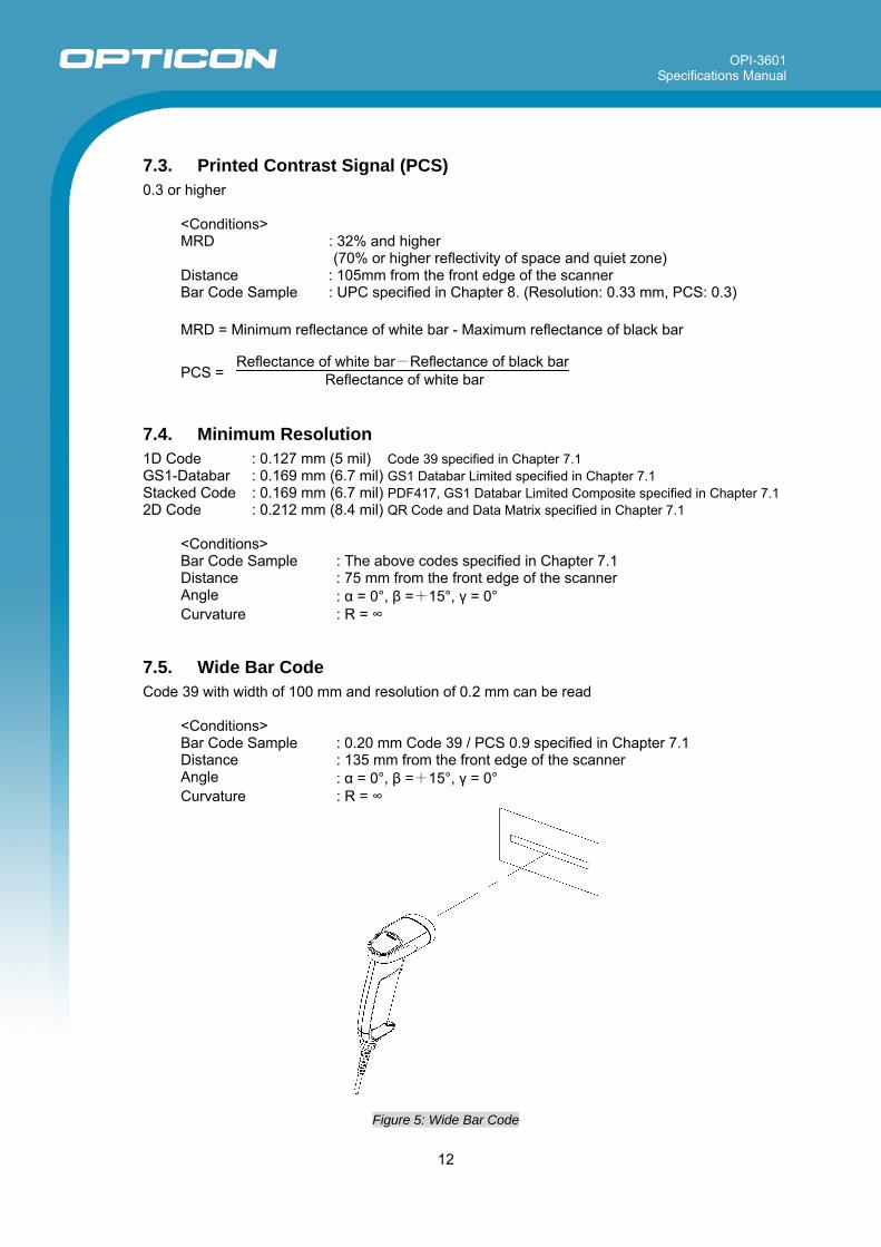
7.5. Wide Bar Code Code 39 with width of 100 mm and resolution of 0.2 mm can be read
<Conditions> Bar Code Sample : 0.20 mm Code 39 / PCS 0.9 specified in Chapter 7.1 Distance : 135 mm from the front edge of the scanner Angle : α = 0°, β =+15°, γ = 0° Curvature : R = ∞
Figure 5: Wide Bar Code
OPI-3601 Specifications Manual
13
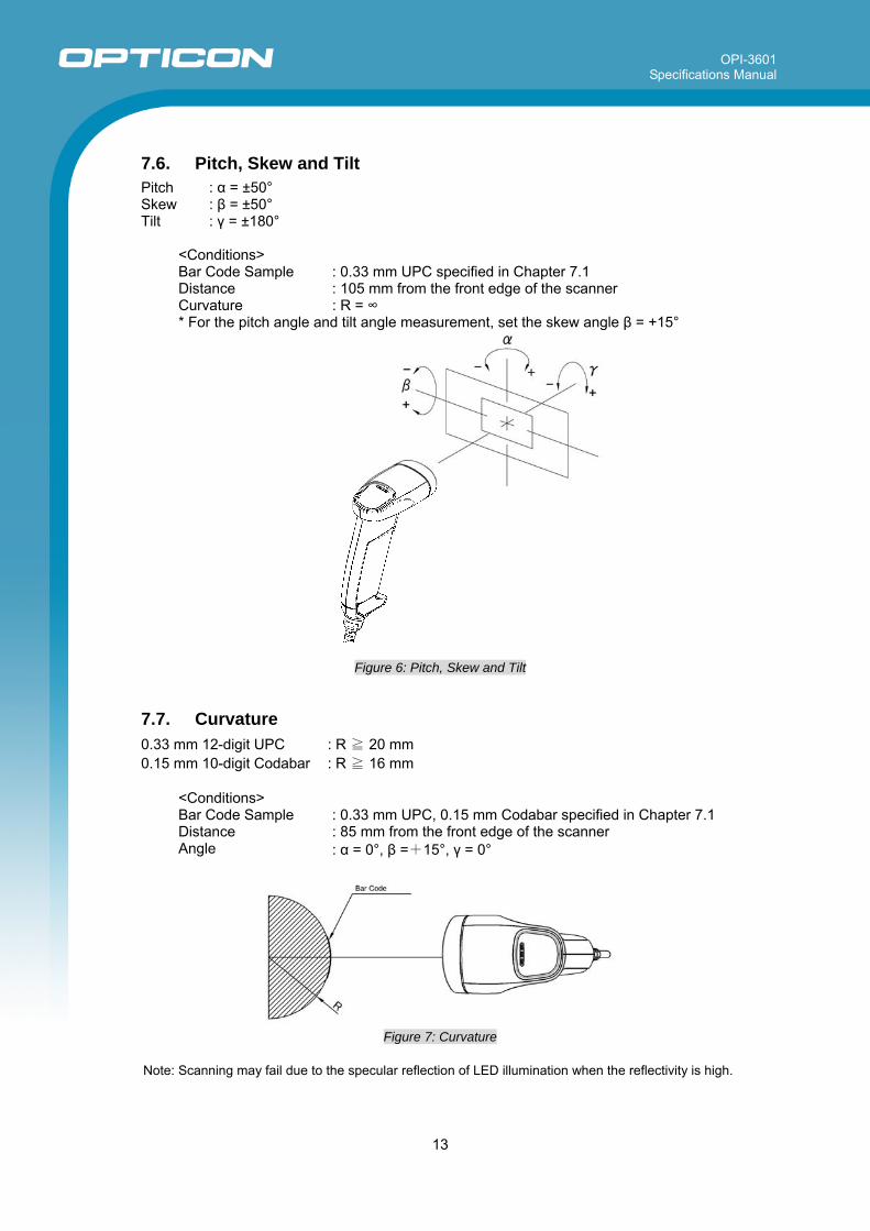
7.6. Pitch, Skew and Tilt Pitch : α = ±50° Skew : β = ±50° Tilt : γ = ±180°
<Conditions> Bar Code Sample : 0.33 mm UPC specified in Chapter 7.1 Distance : 105 mm from the front edge of the scanner Curvature : R = ∞ * For the pitch angle and tilt angle measurement, set the skew angle β = +15°
Figure 6: Pitch, Skew and Tilt
7.7. Curvature 0.33 mm 12-digit UPC : R ≧ 20 mm 0.15 mm 10-digit Codabar : R ≧ 16 mm
<Conditions> Bar Code Sample : 0.33 mm UPC, 0.15 mm Codabar specified in Chapter 7.1 Distance : 85 mm from the front edge of the scanner Angle : α = 0°, β =+15°, γ = 0°
Figure 7: Curvature
Note: Scanning may fail due to the specular reflection of LED illumination when the reflectivity is high.
OPI-3601 Specifications Manual
14
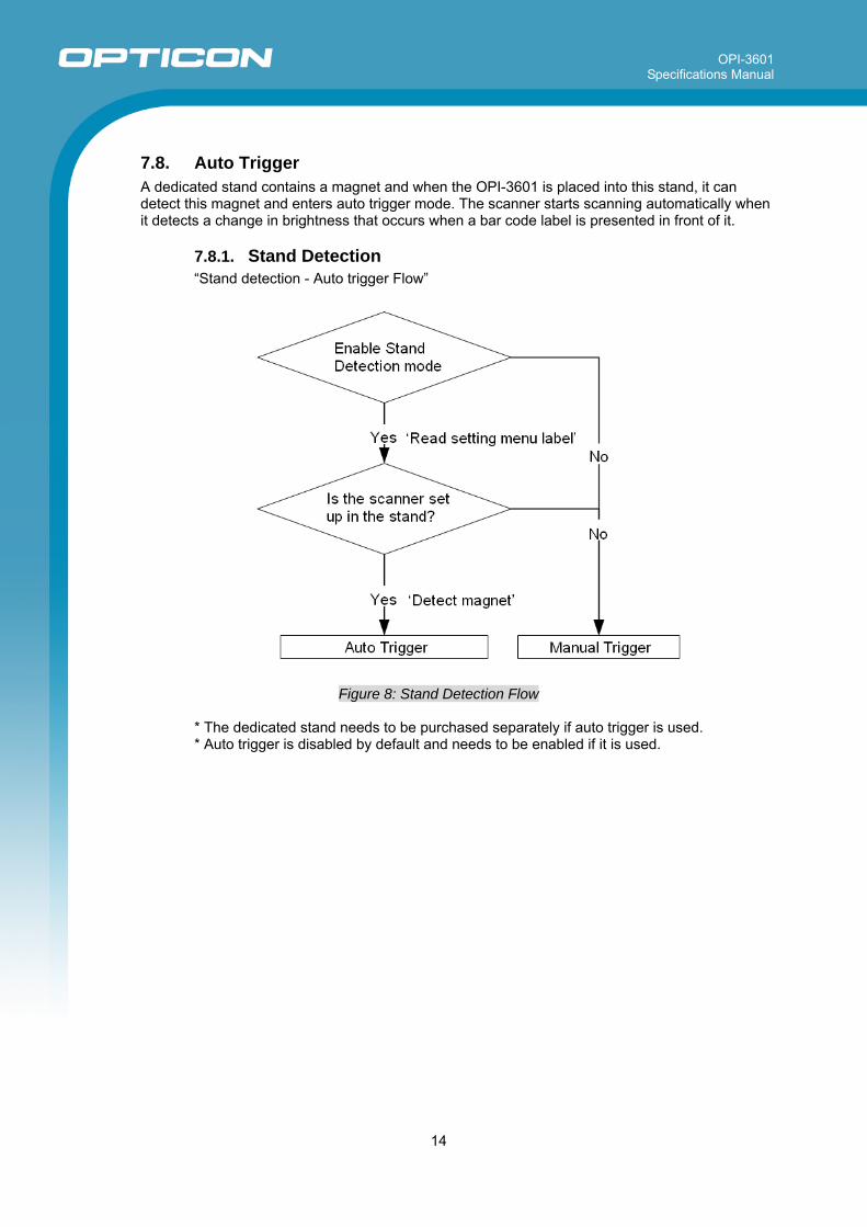
7.8. Auto Trigger A dedicated stand contains a magnet and when the OPI-3601 is placed into this stand, it can detect this magnet and enters auto trigger mode. The scanner starts scanning automatically when it detects a change in brightness that occurs when a bar code label is presented in front of it.
7.8.1. Stand Detection “Stand detection - Auto trigger Flow”
Figure 8: Stand Detection Flow
* The dedicated stand needs to be purchased separately if auto trigger is used. * Auto trigger is disabled by default and needs to be enabled if it is used.
OPI-3601 Specifications Manual
15
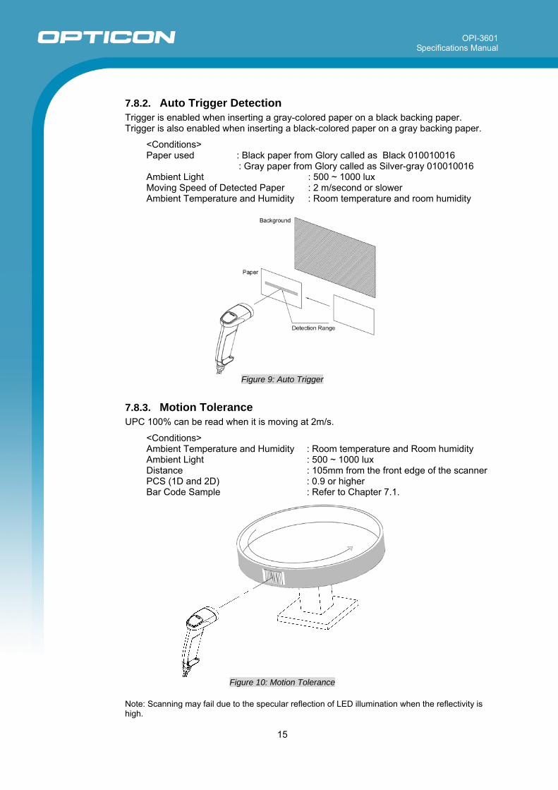
7.8.2. Auto Trigger Detection Trigger is enabled when inserting a gray-colored paper on a black backing paper. Trigger is also enabled when inserting a black-colored paper on a gray backing paper.
<Conditions> Paper used : Black paper from Glory called as Black 010010016 : Gray paper from Glory called as Silver-gray 010010016 Ambient Light : 500 ~ 1000 lux Moving Speed of Detected Paper : 2 m/second or slower Ambient Temperature and Humidity : Room temperature and room humidity
Figure 9: Auto Trigger
7.8.3. Motion Tolerance UPC 100% can be read when it is moving at 2m/s.
<Conditions> Ambient Temperature and Humidity : Room temperature and Room humidity Ambient Light : 500 ~ 1000 lux Distance : 105mm from the front edge of the scanner PCS (1D and 2D) : 0.9 or higher Bar Code Sample : Refer to Chapter 7.1.
Figure 10: Motion Tolerance
Note: Scanning may fail due to the specular reflection of LED illumination when the reflectivity is high.
OPI-3601 Specifications Manual
16
8. Interface Specifications The OPI-3601 supports four types of interfaces; RS-232C, USB-HID, USB-COM and Wedge/PS2.
8.1. RS-232C 8.1.1. Communication Setting Baud rate : 300 ~ 115200 bps Data length : 7 / 8 bits Parity bits : No / Even / Odd parity Stop bits : 1 / 2 bit * Multi byte character data or images can be transmitted via RS-232C interface.
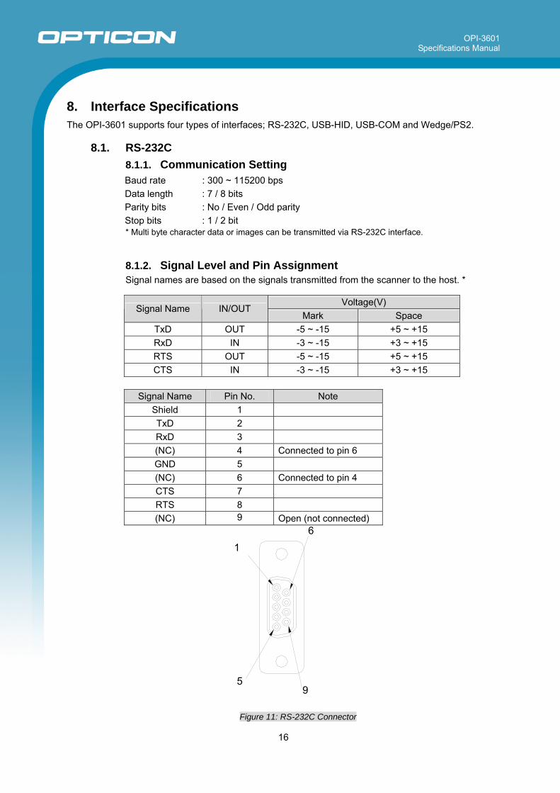
8.1.2. Signal Level and Pin Assignment Signal names are based on the signals transmitted from the scanner to the host. *
Voltage(V) Signal Name IN/OUT
Mark Space TxD OUT -5 ~ -15 +5 ~ +15 RxD IN -3 ~ -15 +3 ~ +15 RTS OUT -5 ~ -15 +5 ~ +15 CTS IN -3 ~ -15 +3 ~ +15
Signal Name Pin No. Note Shield 1 TxD 2 RxD 3 (NC) 4 Connected to pin 6 GND 5 (NC) 6 Connected to pin 4 CTS 7 RTS 8 (NC) 9 Open (not connected)
Figure 11: RS-232C Connector
1
5 9
6
OPI-3601 Specifications Manual
17
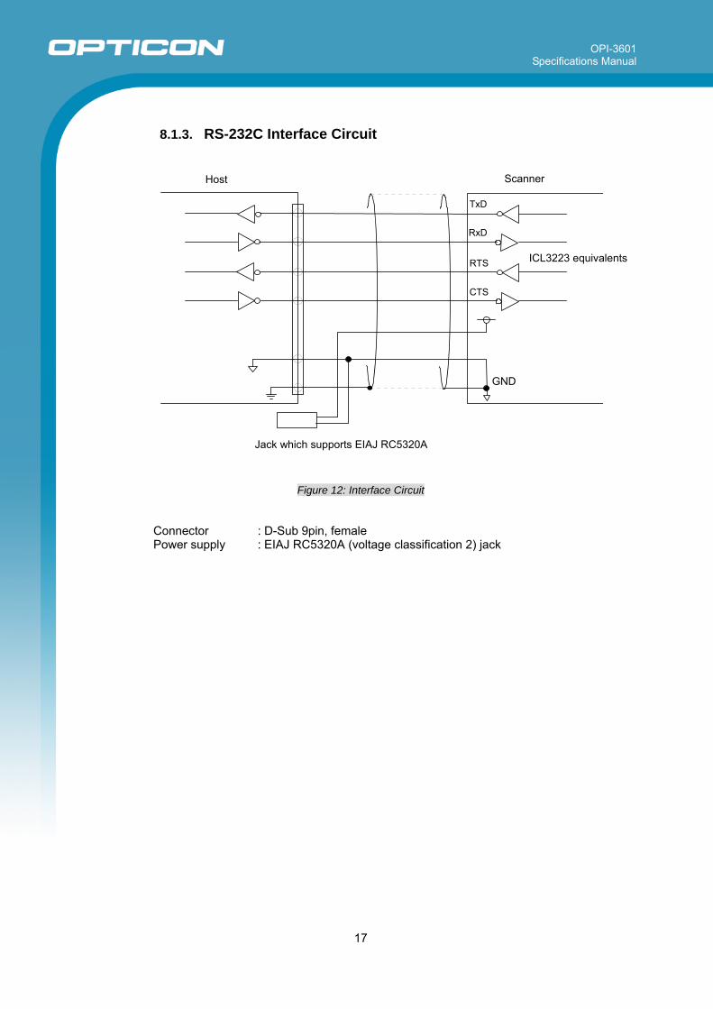
8.1.3. RS-232C Interface Circuit
Figure 12: Interface Circuit
Connector : D-Sub 9pin, female Power supply : EIAJ RC5320A (voltage classification 2) jack
Host
TxD
RxD
RTS
CTS
GND
Jack which supports EIAJ RC5320A
Scanner
ICL3223 equivalents
OPI-3601 Specifications Manual
18
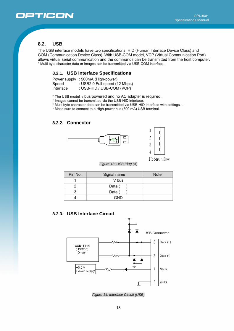
8.2. USB The USB interface models have two specifications: HID (Human Interface Device Class) and COM (Communication Device Class). With USB-COM model, VCP (Virtual Communication Port) allows virtual serial communication and the commands can be transmitted from the host computer. * Multi byte character data or images can be transmitted via USB-COM interface.
8.2.1. USB Interface Specifications Power supply : 500mA (High-power) Speed : USB2.0 Full-speed (12 Mbps) Interface : USB-HID / USB-COM (VCP)
* The USB model is bus powered and no AC adapter is required. * Images cannot be transmitted via the USB-HID interface. * Multi byte character data can be transmitted via USB-HID interface with settings. . * Make sure to connect to a High-power bus (500 mA) USB terminal.
8.2.2. Connector
Figure 13: USB Plug (A)
Pin No. Signal name Note 1 V bus
2 Data ( - )
3 Data ( + )
4 GND
8.2.3. USB Interface Circuit
Figure 14: Interface Circuit (USB)
OPI-3601 Specifications Manual
19
8.3. Wedge PS/2
8.3.1. How to Connect ・Connect the branch cable (without label on, 6-pin Mini-DIN female) to the OPI-3601
Wedge PS/2 interface cable connector (6-pin Mini-DIN male).
・Connect the branch cable connector (6-Pin Mini-DIN male) to the host keyboard connector.
・Connect the other branch cable connector (with DOS/V KEY label on, 6-pin Mini-DIN,
female) to the keyboard.
・Insert the AC adapter plug to the DC jack of the interface cable and start the host computer.
8.3.2. Caution ・Do not operate on the keyboard during the data transmission to the host or the data
transmission may fail. ・The keyboard can operate without connecting to the AC adapter when this device is not
used. However, do not turn ON or OFF the adapter while operating on the keyboard. It may cause malfunctions.
・Images cannot be transmitted via this Wedge PS/2 interface. ・Multi byte character data can be transmitted via this Wedge PS/2 interface with settings. ・Do not start any scanning operation or keyboard operation before the OS of the host
computer is fully activated.
OPI-3601 Specifications Manual
20
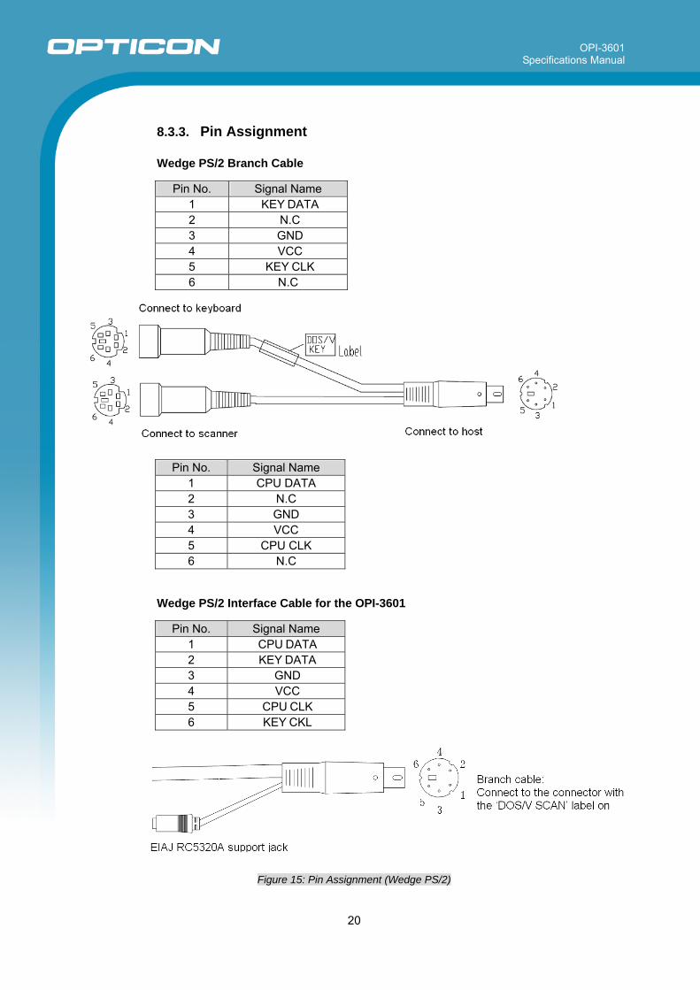
8.3.3. Pin Assignment Wedge PS/2 Branch Cable
Pin No. Signal Name 1 KEY DATA 2 N.C 3 GND 4 VCC 5 KEY CLK 6 N.C
Pin No. Signal Name
1 CPU DATA 2 N.C 3 GND 4 VCC 5 CPU CLK 6 N.C
Wedge PS/2 Interface Cable for the OPI-3601
Pin No. Signal Name 1 CPU DATA 2 KEY DATA 3 GND 4 VCC 5 CPU CLK 6 KEY CKL
Figure 15: Pin Assignment (Wedge PS/2)
OPI-3601 Specifications Manual
21
9. Cable and Connector
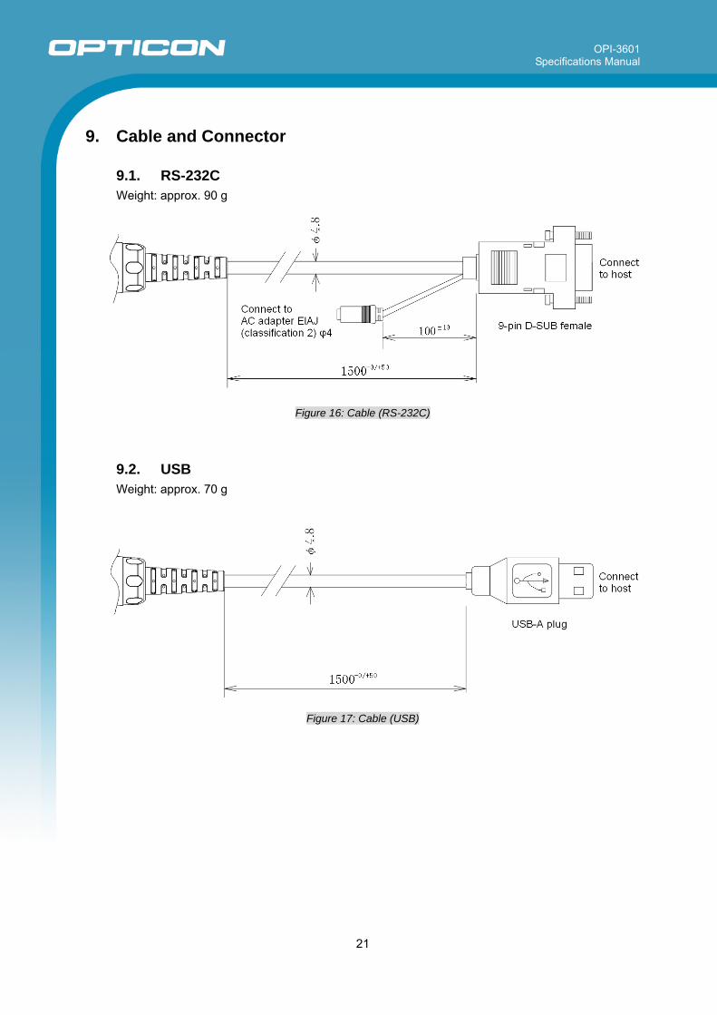
9.1. RS-232C Weight: approx. 90 g
Figure 16: Cable (RS-232C)
9.2. USB Weight: approx. 70 g
Figure 17: Cable (USB)
OPI-3601 Specifications Manual
22
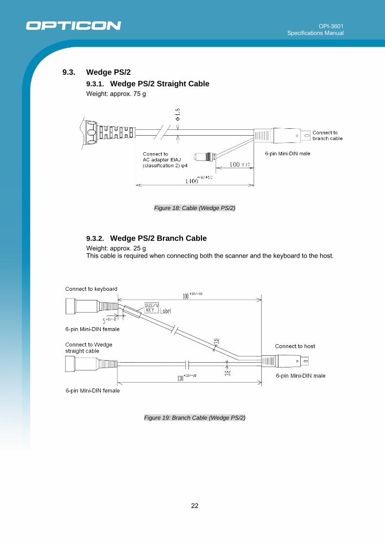
9.3. Wedge PS/2
9.3.1. Wedge PS/2 Straight Cable Weight: approx. 75 g
Figure 18: Cable (Wedge PS/2)
9.3.2. Wedge PS/2 Branch Cable Weight: approx. 25 g This cable is required when connecting both the scanner and the keyboard to the host.
Figure 19: Branch Cable (Wedge PS/2)
OPI-3601 Specifications Manual
23
10. Environmental Specifications
10.1. Temperature Scanning performance is guaranteed when the range of ambient temperature around the scanner is the following values:
Operating Temperature : -20 ~ 50 °C Storage Temperature : -20 ~ 60 °C
<Conditions> Bar Code Sample : 0.33 mm UPC specified in Chapter 7.1 Distance : 105 mm from the front edge of the scanner Angle : α = 0°, β =+15°, γ = 0° Curvature : R = ∞ Scanning Test : Read at intervals of 300 ms
10.2. Humidity Scanning performance is guaranteed when the range of ambient humidity around the scanner is the following values:
Operating Humidity : 5 ~ 90% RH (no condensation, no frost) Storage Humidity : 5 ~ 90% RH (no condensation, no frost)
<Conditions> Bar Code Sample : 0.33 mm UPC specified in Chapter 7.1 Distance : 75 mm from the front edge of the scanner Angle : α = 0°, β =+15°, γ = 0° Curvature : R = ∞
OPI-3601 Specifications Manual
24
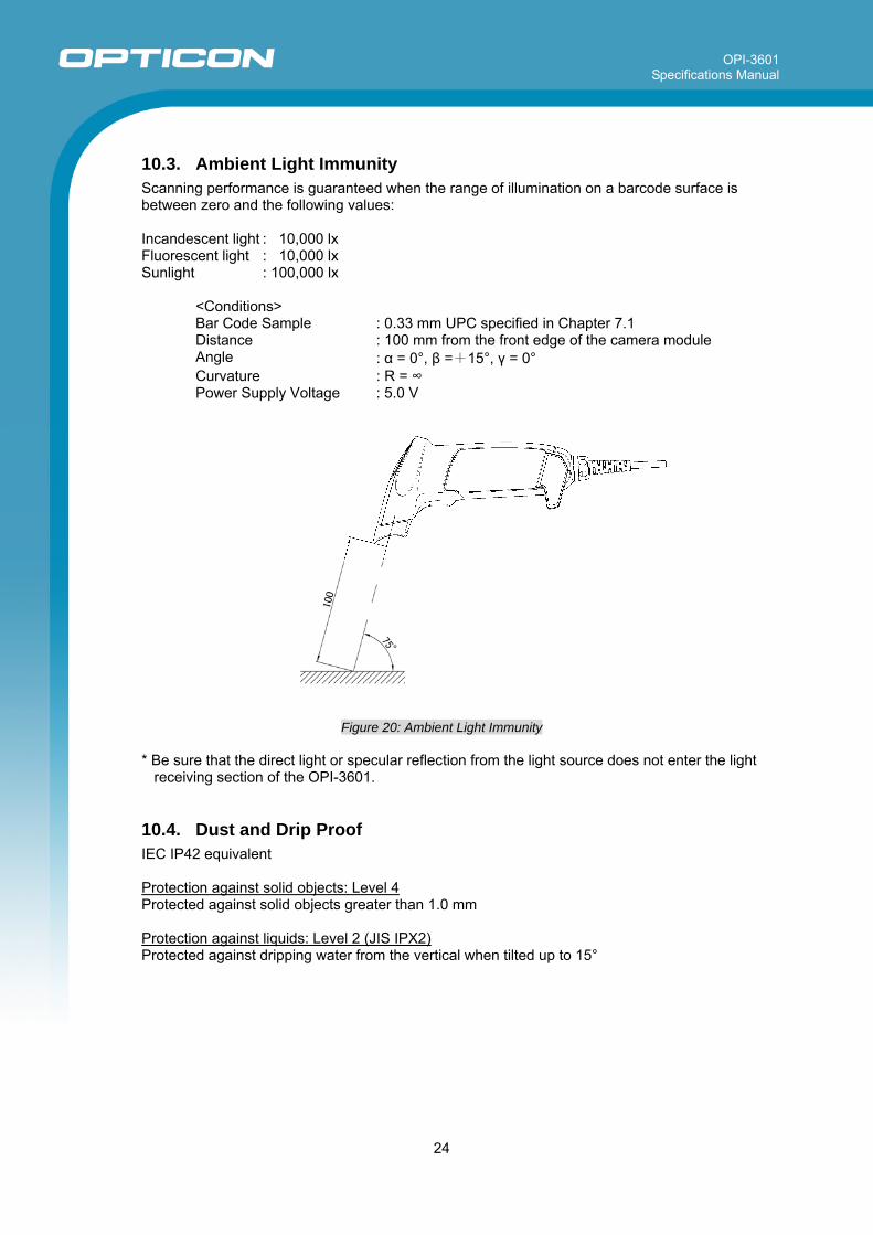
10.3. Ambient Light Immunity Scanning performance is guaranteed when the range of illumination on a barcode surface is between zero and the following values:
Incandescent light : 10,000 lx Fluorescent light : 10,000 lx Sunlight : 100,000 lx
<Conditions> Bar Code Sample : 0.33 mm UPC specified in Chapter 7.1 Distance : 100 mm from the front edge of the camera module Angle : α = 0°, β =+15°, γ = 0° Curvature : R = ∞ Power Supply Voltage : 5.0 V
Figure 20: Ambient Light Immunity
* Be sure that the direct light or specular reflection from the light source does not enter the light
receiving section of the OPI-3601.
10.4. Dust and Drip Proof IEC IP42 equivalent
Protection against solid objects: Level 4 Protected against solid objects greater than 1.0 mm
Protection against liquids: Level 2 (JIS IPX2) Protected against dripping water from the vertical when tilted up to 15°
OPI-3601 Specifications Manual
25
10.5. Cable Strength There shall be no sign of malfunction after the following cable strength test. Cable Strength Test: Affix the scanner to an immovable object and pull it using a force of 24.5 N (2.5 kgf static loading) for 1 second. Repeat this 20 times continuously.
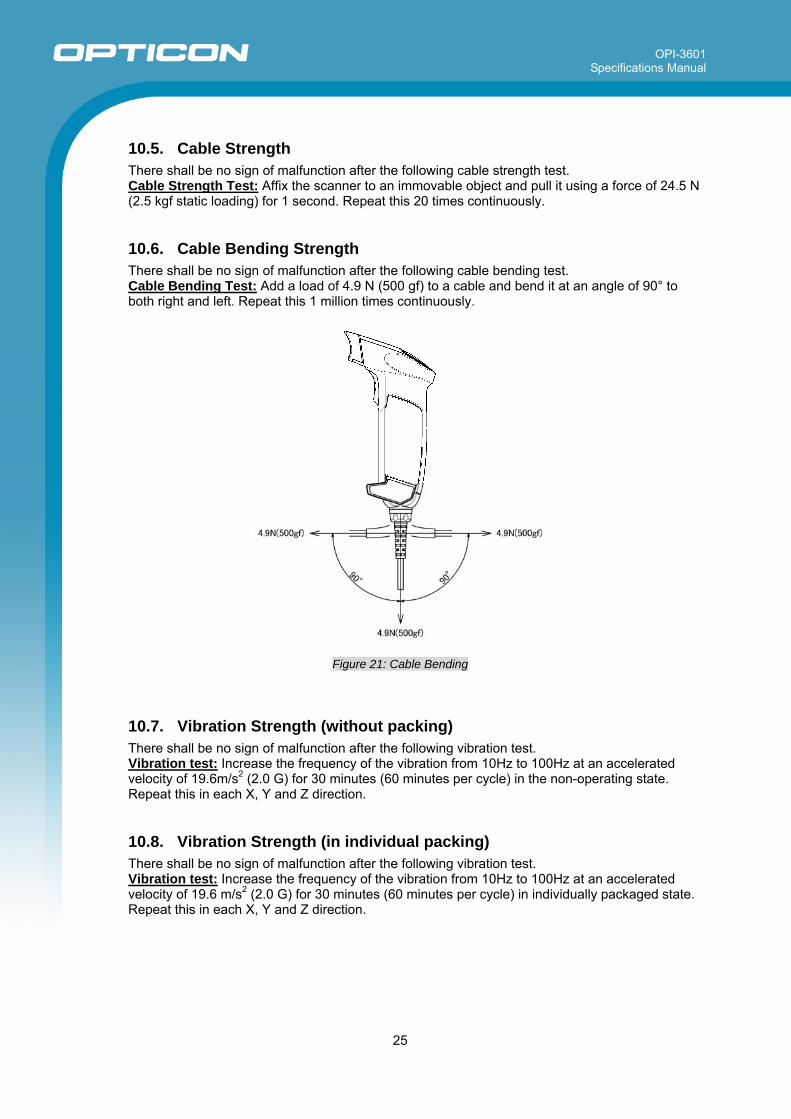
10.6. Cable Bending Strength There shall be no sign of malfunction after the following cable bending test. Cable Bending Test: Add a load of 4.9 N (500 gf) to a cable and bend it at an angle of 90° to both right and left. Repeat this 1 million times continuously.
Figure 21: Cable Bending
10.7. Vibration Strength (without packing) There shall be no sign of malfunction after the following vibration test. Vibration test: Increase the frequency of the vibration from 10Hz to 100Hz at an accelerated velocity of 19.6m/s2 (2.0 G) for 30 minutes (60 minutes per cycle) in the non-operating state. Repeat this in each X, Y and Z direction.
10.8. Vibration Strength (in individual packing) There shall be no sign of malfunction after the following vibration test. Vibration test: Increase the frequency of the vibration from 10Hz to 100Hz at an accelerated velocity of 19.6 m/s2 (2.0 G) for 30 minutes (60 minutes per cycle) in individually packaged state. Repeat this in each X, Y and Z direction.
OPI-3601 Specifications Manual
26
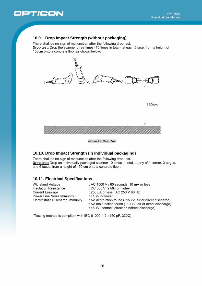
10.9. Drop Impact Strength (without packaging) There shall be no sign of malfunction after the following drop test. Drop test: Drop the scanner three times (15 times in total), at each 5 face, from a height of 150cm onto a concrete floor as shown below.
Figure 22: Drop Test
10.10. Drop Impact Strength (in individual packaging) There shall be no sign of malfunction after the following drop test. Drop test: Drop an individually packaged scanner 10 times in total, at any of 1 corner, 3 edges, and 6 faces, from a height of 150 cm onto a concrete floor.
10.11. Electrical Specifications Withstand Voltage : AC 1500 V / 60 seconds, 10 mA or less Insulation Resistance : DC 500 V, 2 MΩ or higher Current Leakage : 250 μA or less / AC 250 V 60 Hz Power Line Noise Immunity : ±1 kV or lower Electrostatic Discharge Immunity : No destruction found (±15 kV, air or direct discharge) : No malfunction found (±10 kV, air or direct discharge) : ±6 kV (contact, direct or indirect discharge)
*Testing method is compliant with IEC-61000-4-2. (150 pF, 330Ω)
OPI-3601 Specifications Manual
27
11. Default Setting
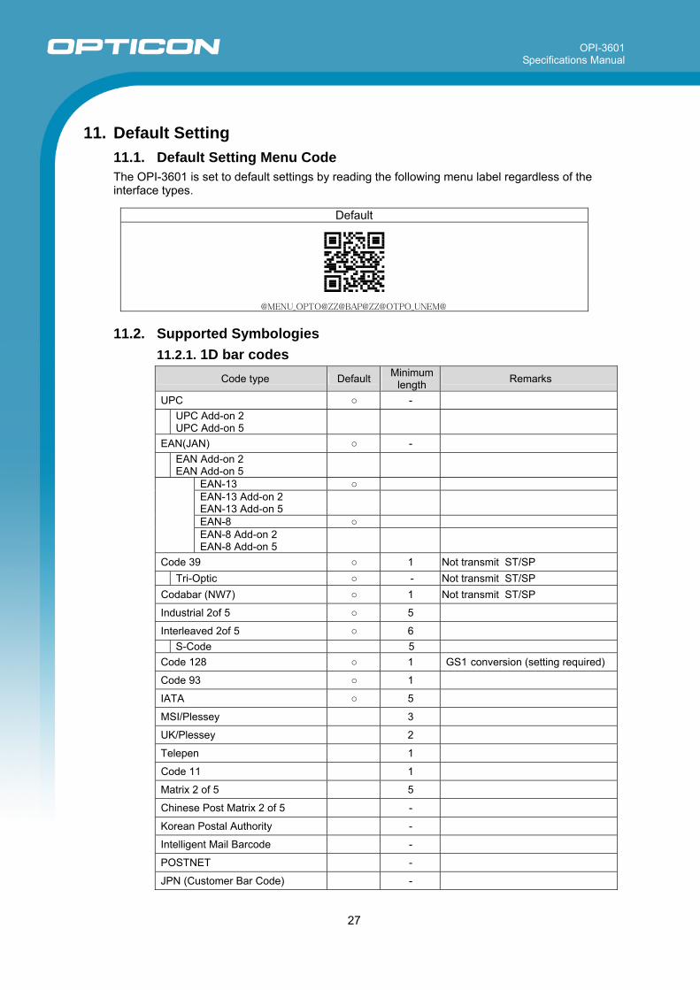
11.1. Default Setting Menu Code The OPI-3601 is set to default settings by reading the following menu label regardless of the interface types.
Default
@MENU_OPTO@ZZ@BAP@ZZ@OTPO_UNEM@
11.2. Supported Symbologies 11.2.1. 1D bar codes
Code type Default Minimum length Remarks
UPC -
UPC Add-on 2 UPC Add-on 5
EAN(JAN) -
EAN Add-on 2 EAN Add-on 5
EAN-13 EAN-13 Add-on 2 EAN-13 Add-on 5
EAN-8
EAN-8 Add-on 2 EAN-8 Add-on 5
Code 39 1 Not transmit ST/SP Tri-Optic - Not transmit ST/SP Codabar (NW7) 1 Not transmit ST/SP
Industrial 2of 5 5
Interleaved 2of 5 6 S-Code 5 Code 128 1 GS1 conversion (setting required)
Code 93 1
IATA 5
MSI/Plessey 3
UK/Plessey 2
Telepen 1
Code 11 1
Matrix 2 of 5 5
Chinese Post Matrix 2 of 5 -
Korean Postal Authority -
Intelligent Mail Barcode -
POSTNET -
JPN (Customer Bar Code) -
OPI-3601 Specifications Manual
28
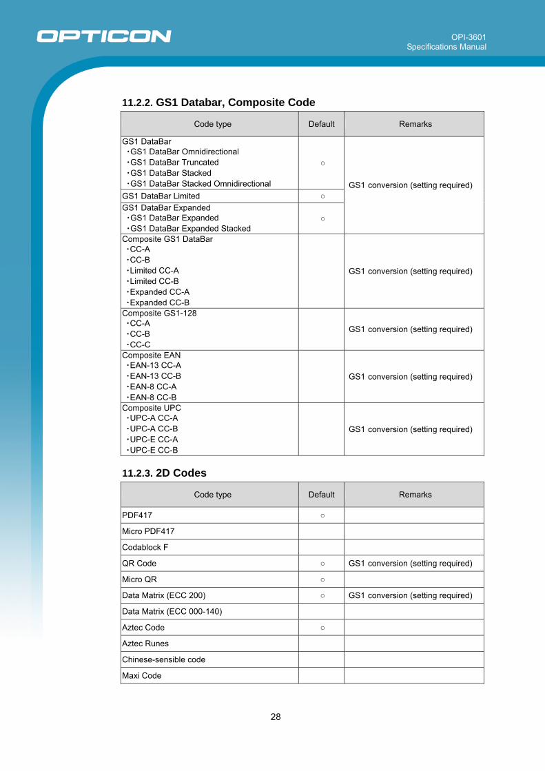
11.2.2. GS1 Databar, Composite Code
Code type Default Remarks
GS1 DataBar ・GS1 DataBar Omnidirectional ・GS1 DataBar Truncated ・GS1 DataBar Stacked ・GS1 DataBar Stacked Omnidirectional
GS1 DataBar Limited GS1 DataBar Expanded ・GS1 DataBar Expanded ・GS1 DataBar Expanded Stacked
GS1 conversion (setting required)
Composite GS1 DataBar ・CC-A ・CC-B ・Limited CC-A ・Limited CC-B ・Expanded CC-A ・Expanded CC-B
GS1 conversion (setting required)
Composite GS1-128 ・CC-A ・CC-B ・CC-C
GS1 conversion (setting required)
Composite EAN ・EAN-13 CC-A ・EAN-13 CC-B ・EAN-8 CC-A ・EAN-8 CC-B
GS1 conversion (setting required)
Composite UPC ・UPC-A CC-A ・UPC-A CC-B ・UPC-E CC-A ・UPC-E CC-B
GS1 conversion (setting required)
11.2.3. 2D Codes
Code type Default Remarks
PDF417
Micro PDF417
Codablock F
QR Code GS1 conversion (setting required)
Micro QR
Data Matrix (ECC 200) GS1 conversion (setting required)
Data Matrix (ECC 000-140)
Aztec Code
Aztec Runes
Chinese-sensible code
Maxi Code
OPI-3601 Specifications Manual
29
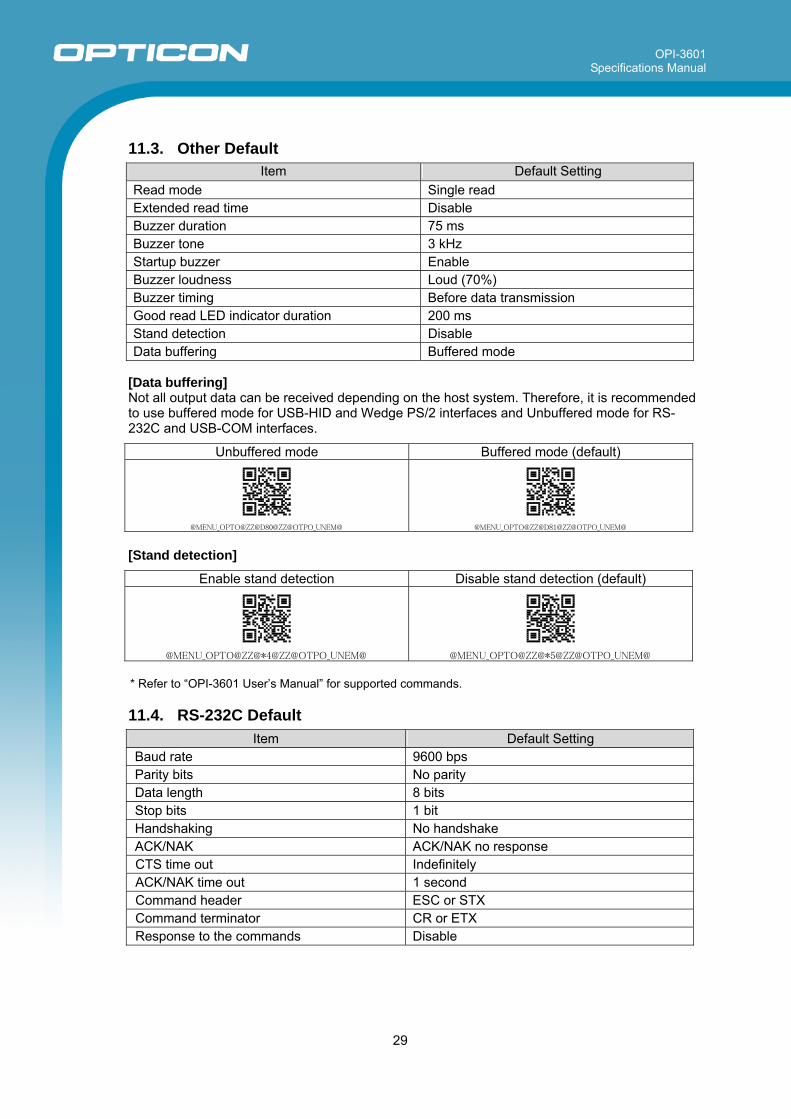
11.3. Other Default
Item Default Setting Read mode Single read Extended read time Disable Buzzer duration 75 ms Buzzer tone 3 kHz Startup buzzer Enable Buzzer loudness Loud (70%) Buzzer timing Before data transmission Good read LED indicator duration 200 ms Stand detection Disable Data buffering Buffered mode
[Data buffering] Not all output data can be received depending on the host system. Therefore, it is recommended to use buffered mode for USB-HID and Wedge PS/2 interfaces and Unbuffered mode for RS-232C and USB-COM interfaces.
Unbuffered mode Buffered mode (default)
@MENU_OPTO@ZZ@D80@ZZ@OTPO_UNEM@ @MENU_OPTO@ZZ@D81@ZZ@OTPO_UNEM@
[Stand detection]
Enable stand detection Disable stand detection (default)
@MENU_OPTO@ZZ@*4@ZZ@OTPO_UNEM@ @MENU_OPTO@ZZ@*5@ZZ@OTPO_UNEM@
* Refer to “OPI-3601 User’s Manual” for supported commands.
11.4. RS-232C Default Item Default Setting
Baud rate 9600 bps Parity bits No parity Data length 8 bits Stop bits 1 bit Handshaking No handshake ACK/NAK ACK/NAK no response CTS time out Indefinitely ACK/NAK time out 1 second Command header ESC or STX Command terminator CR or ETX Response to the commands Disable
OPI-3601 Specifications Manual
30
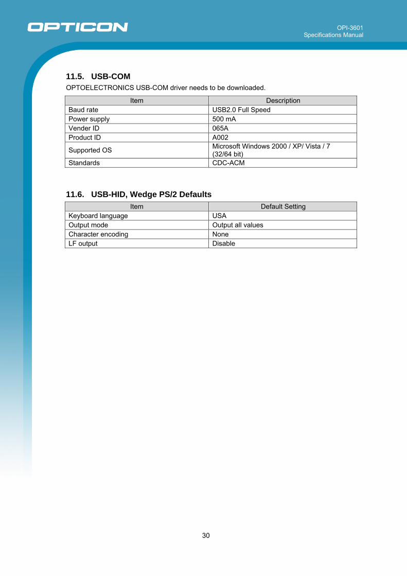
11.5. USB-COM OPTOELECTRONICS USB-COM driver needs to be downloaded.
Item Description Baud rate USB2.0 Full Speed Power supply 500 mA Vender ID 065A Product ID A002
Supported OS Microsoft Windows 2000 / XP/ Vista / 7 (32/64 bit)
Standards CDC-ACM
11.6. USB-HID, Wedge PS/2 Defaults
Item Default Setting Keyboard language USA Output mode Output all values Character encoding None LF output Disable
OPI-3601 Specifications Manual
31
This device complies with part 15 of the FCC Rules. Operation is subject to the following two conditions: ( 1 ) this device may not cause harmful Interference, and ( 2 ) this device must accept any interference received, including interference that may cause undesired operation.
12. Regulatory Compliance
12.1. LED Safety IIEC 62471-1:2006 Exempt Risk Group
12.2. EMC EN55022 EN55024 FCC Part 15 Subpart B Class B
VCCI Class B
13. RoHS The OPI-3601 is compliant with RoHS.
RoHS: The restriction of the use of certain hazardous substances in electrical and electronic equipment, 2002/95/EC
14. Reliability MTBF (Mean Time Between Failures) 47,480 hours Note: The reliability of the OPI-3601 is guaranteed as far as it is operated under normal operating conditions in the
range of advised operating temperature and without excessive electrical or mechanical shock. 15. Precautions Handle this product carefully. Do not deliberately subject it to any of the following. (1) Shock
・Do not drop from the non-standard height. ・Do not swing around the cable. ・Do not place any heavy items on the scanner. ・Do not squeeze it between any heavy items.
(2) Temperature Conditions
・Do not use the scanner at temperatures outside the specified range. ・Do not pour boiling water on the scanner. ・Do not throw the scanner into the fire. ・Do not bend cables forcibly at low temperatures.
(3) Foreign Materials
・Do not put the scanner into water. ・Do not put the scanner into chemicals.
(4) Others
・Do not plug/unplug the connectors when the laser beam is emitted. ・Do not disassemble this product. ・Do not use the scanner near a radio or a TV receiver. It may cause reception problems. ・The scanner may be damaged by voltage drops caused by lightning. ・The scanner may not perform properly in environments when placed near a magnetic material.
This is a Class B product, to be used in a domestic environment, based on the Technical Requirement of the Voluntary Control Council for Interference from Information Technology Equipment (VCCI). If this is used near a radio or television receiver in a domestic environment, it may cause radio interference.
OPI-3601 Specifications Manual
32
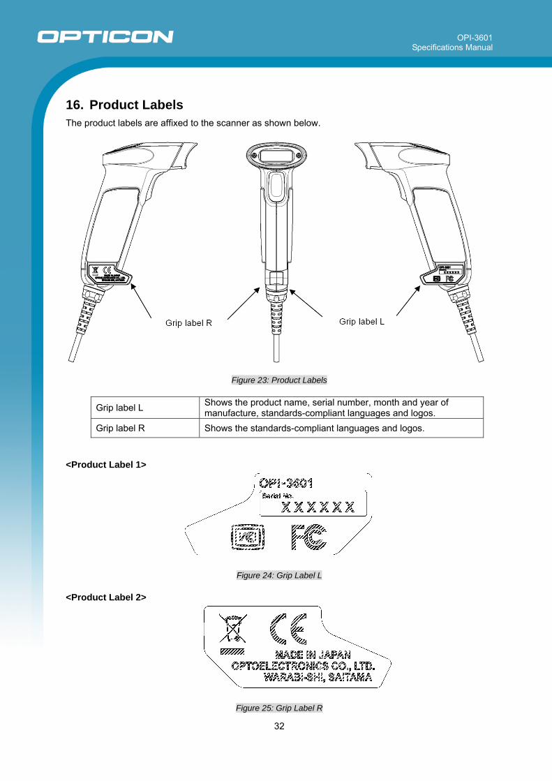
16. Product Labels The product labels are affixed to the scanner as shown below.
Figure 23: Product Labels
Grip label L Shows the product name, serial number, month and year of manufacture, standards-compliant languages and logos.
Grip label R Shows the standards-compliant languages and logos. <Product Label 1>
Figure 24: Grip Label L <Product Label 2>
Figure 25: Grip Label R
OPI-3601 Specifications Manual
33
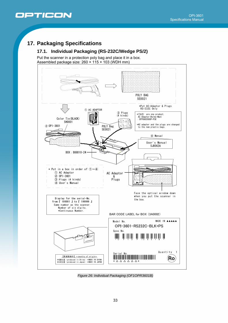
17. Packaging Specifications
17.1. Individual Packaging (RS-232C/Wedge PS/2) Put the scanner in a protection poly bag and place it in a box. Assembled package size: 260 × 115 × 103 (WDH mm)
POLY BAGOPR32018008C0-00
AC Adaptor&Plugs
User's Manual(5J0062A-C)
Face the optical window downwhen you put the scanner in
the box.
Color Tie(Black)
BOX:OPR32018001C0-00
*Put AC-Adaptor & PlugsRS-232C Only
*①&③ are one product.AC Adapter(Helms-Man)
:SFP0602000P-PSE
*AC adapter and the plugs are changedto the new plastic bags.② OPR-3201
④ Manual
* Put in a box in order of ①~④① AC Adaptor② OPR-3201③ Plugs (4 kinds)④ User's Manual
① AC ADAPTOR③ Plugs(4 kinds)
Plastic BagOPR32018008C0-00
MADE IN Model No.
MODEL NEME
Spec No.
* ハ ゙ ー コ ー ト ゙ *
* *
Serial No.Qu a n ti t y 1
Item No.
Ro
*O F 1 O P I3 6 0 1 B *
*-*
OPI-3601-RS232C-BLK+PS
Display for the serial-No.
from『 100001 』to『 199999 』
Same number as the scanner.Number of six digits.*Continuous Number.
BAR CODE LABEL for BOX (3A0002)
【原産国表示】~country of origin~
中国生産(produced in China)=MADE IN CHINA日本生産(produced in Japan)=MADE IN JAPAN
5J0062A
BOX:B88010-24
POLY Bag5E0021
POLY BAG5E0021
OPI-3601
Color Tie(BLACK)5H0001
OPI-3601
Figure 26: Individual Packaging (OF1OPR3601B)
OPI-3601 Specifications Manual
34
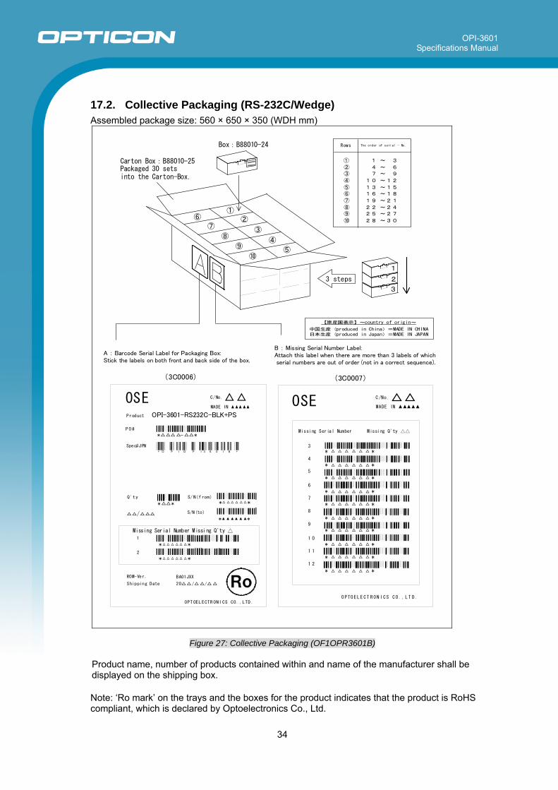
17.2. Collective Packaging (RS-232C/Wedge) Assembled package size: 560 × 650 × 350 (WDH mm)
②
③
④
⑤
⑥
⑦
⑧
⑨
⑩
①
Box OPR32018001C0-00
Carton box:OPR32018002C0-00Packaged 30 sets
into the Carton-Box
1
2
3
Rows The order of serial - No.
① 1 ~ 3
② 4 ~ 6③ 7 ~ 9
④ 10 ~12
⑤ 13 ~15⑥ 16 ~18
⑦ 19 ~21
⑧ 22 ~24⑨ 25 ~27
⑩ 28 ~30
3 steps
(3C0006) (3C0007)
C /No.MADE IN
3* *
O P TO E L E C T R O N I C S C O . , L T D .
Missing Serial Number Missing Q'ty
4
5
6
7
8
9
1 0
1 1
1 2
OSE
* *
* *
* *
* *
* *
* *
* *
* *
* *
A : Barcode Serial Label for Packaging Box:Stick the labels on both front and back side of the box.
B : Missing Serial Number Label:Attach this label when there are more than 3 labels of which serial numbers are out of order (not in a correct sequence).
OSE C/No.MADE IN
Product MODEL名
PO#
*-*
Spec#JPN バーコード
Q'ty
**
/
S/N(f rom)
* *
S/N(to)
* *
Missing Serial Number Missing Q'ty 1
* *
2
* *
ROM-Ver.
Shipping Date
BA01JXX
20//
OPT OEL ECTR ONI CS CO. ,LTD .
Ro
Spec#EUR バーコード
Spec#USA バーコード
OPI-3601-RS232C-BLK+PS
*-**-*
【原産国表示】~country of origin~
中国生産(produced in China)=MADE IN CHINA日本生産(produced in Japan)=MADE IN JAPAN
Carton Box:B88010-25Packaged 30 setsinto the Carton-Box.
Box:B88010-24
*O F 1 O P I3 6 0 1 B *
Figure 27: Collective Packaging (OF1OPR3601B) Product name, number of products contained within and name of the manufacturer shall be displayed on the shipping box.
Note: ‘Ro mark’ on the trays and the boxes for the product indicates that the product is RoHS compliant, which is declared by Optoelectronics Co., Ltd.
OPI-3601 Specifications Manual
35
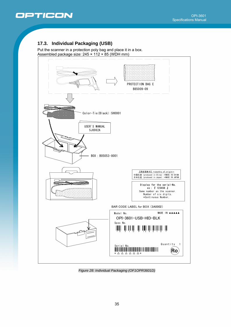
17.3. Individual Packaging (USB) Put the scanner in a protection poly bag and place it in a box. Assembled package size: 245 × 112 × 85 (WDH mm)
PROTECTION BAG E
B85009-09
Color-Tie(Black):5H0001
BOX:B05053-8001
USER'S MANUAL5J0062A
BAR CODE LABEL for BOX (3A0002)
MADE IN Model No.
MODEL NEME
Spec No.
* ハ ゙ ー コ ー ト ゙ *
* *
Serial No.Q u a n t i t y 1
Item No.
Ro
*O F 1 O P I3 6 0 1 D *
*-*
OPI-3601-USB-HID-BLK
【原産国表示】~country of origin~
中国生産(produced in China)=MADE IN CHINA
日本生産(produced in Japan)=MADE IN JAPAN
Display for the serial-No.
ex:『 123456 』
Same number as the scanner.Number of six digits.*Continuous Number.
Figure 28: Individual Packaging (OF1OPR3601D)
OPI-3601 Specifications Manual
36
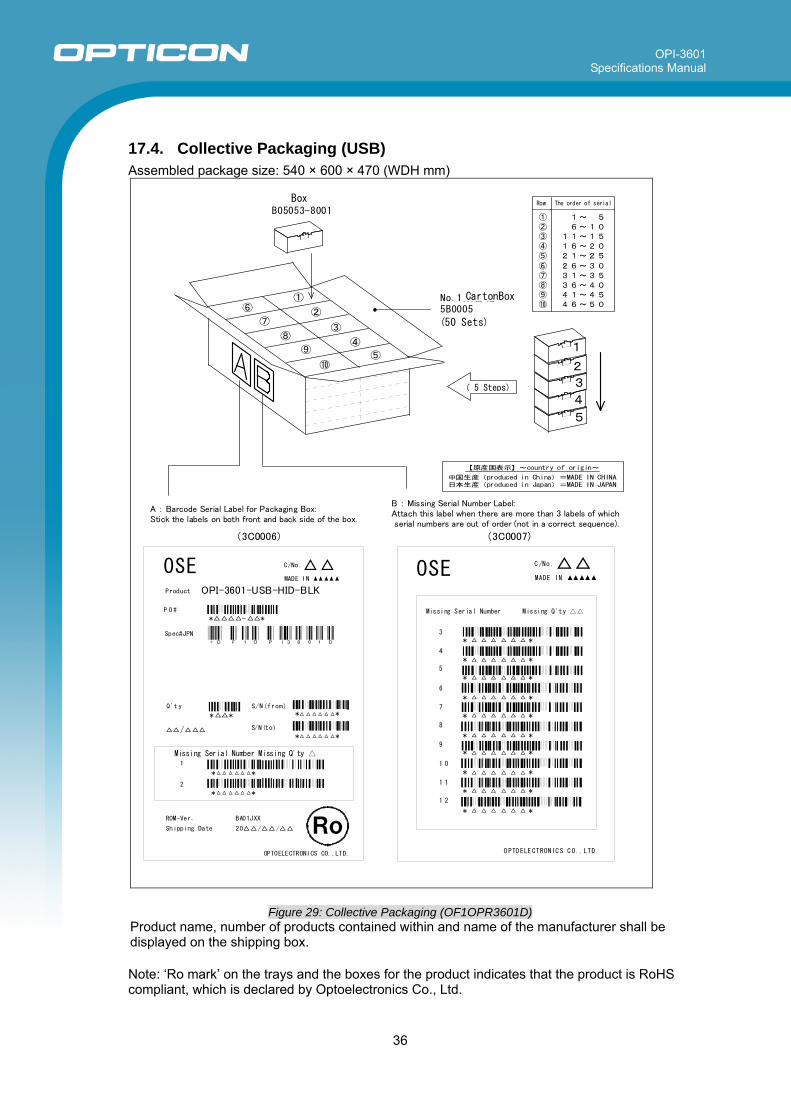
17.4. Collective Packaging (USB) Assembled package size: 540 × 600 × 470 (WDH mm)
(3C0006) (3C0007)
C /No .
3
* *
Missing Serial Number Missing Q'ty
4
5
6
7
8
9
1 0
1 1
1 2
OSE
* *
* *
* *
* *
* *
* *
* *
* *
* *
O PTO ELE CTRONIC S C O., LTD.
MADE IN
A : Barcode Serial Label for Packaging Box:Stick the labels on both front and back side of the box.
B : Missing Serial Number Label:Attach this label when there are more than 3 labels of which serial numbers are out of order (not in a correct sequence).
OSE C/No.MADE IN
Product MODEL名
P O#
*-*
Spec#JPN バ コーート
Q't y
**
/
S/N(from)
S/N(to)
Missing Serial Number Missing Q'ty 1
* *
2
* *
ROM-Ver.
Shipping Date
BA01JXX
20//
OPTOELECTRONICS CO.,LTD.
Ro
Spec#EUR バ コーート
Spec#USA バ コーート
* *
* *
OPI-3601-USB-HID-BLK
*O F 1 O P I3 6 0 1 D
*-*
*-*
【原産国表示】~country of origin~
中国生産(produced in China)=MADE IN CHINA日本生産(produced in Japan)=MADE IN JAPAN
③
④
⑤
⑥
⑦
⑧
⑨
⑩
5 段 入 り
1
2
3
No.1集合箱5B0005
(50台入り)
列 S/Nの順序
① 1~ 5② 6~10③ 11~15④ 16~20⑤ 21~25
⑥ 26~30⑦ 31~35⑧ 36~40⑨ 41~45⑩ 46~50
4
5
①
②
個装箱B05053-8001
Box
CartonBox
(50 Sets)
( 5 Steps)
Row The order of serial
Figure 29: Collective Packaging (OF1OPR3601D) Product name, number of products contained within and name of the manufacturer shall be displayed on the shipping box.
Note: ‘Ro mark’ on the trays and the boxes for the product indicates that the product is RoHS compliant, which is declared by Optoelectronics Co., Ltd.
OPI-3601 Specifications Manual
37
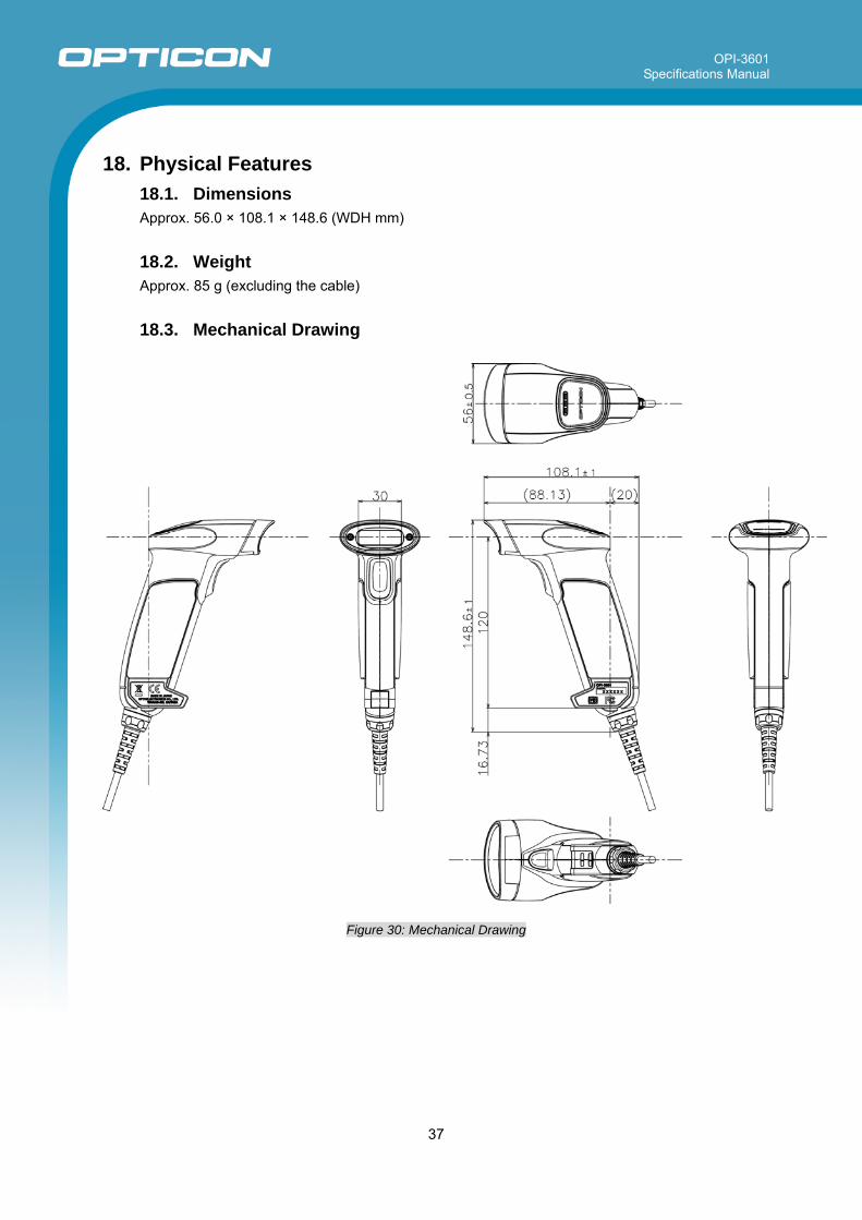
18. Physical Features
18.1. Dimensions Approx. 56.0 × 108.1 × 148.6 (WDH mm)
18.2. Weight Approx. 85 g (excluding the cable)
18.3. Mechanical Drawing
Figure 30: Mechanical Drawing
OPI-3601 Specifications Manual
38
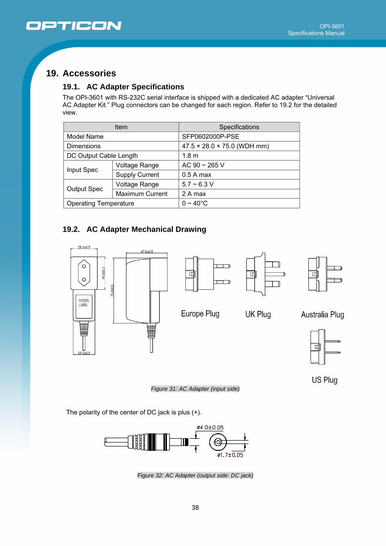
19. Accessories
19.1. AC Adapter Specifications The OPI-3601 with RS-232C serial interface is shipped with a dedicated AC adapter “Universal AC Adapter Kit.” Plug connectors can be changed for each region. Refer to 19.2 for the detailed view.
Item Specifications Model Name SFP0602000P-PSE Dimensions 47.5 × 28.0 × 75.0 (WDH mm) DC Output Cable Length 1.8 m
Voltage Range AC 90 ~ 265 V Input Spec
Supply Current 0.5 A max Voltage Range 5.7 ~ 6.3 V
Output Spec Maximum Current 2 A max
Operating Temperature 0 ~ 40°C
19.2. AC Adapter Mechanical Drawing
Figure 31: AC Adapter (input side)
The polarity of the center of DC jack is plus (+).
Figure 32: AC Adapter (output side: DC jack)
OPI-3601 Specifications Manual
39
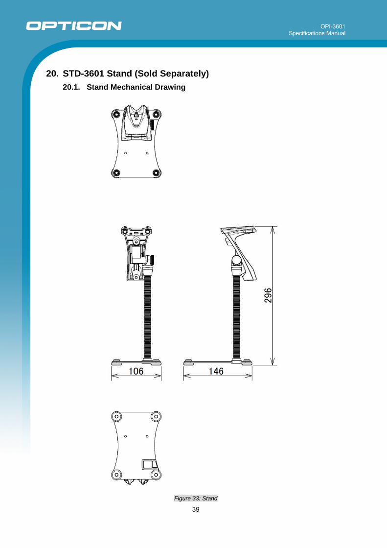
20. STD-3601 Stand (Sold Separately)
20.1. Stand Mechanical Drawing
Figure 33: Stand