Operator’s views of current status and future research -...
26
Operator’s views of current status and future research - H 2 S Cracking John Martin BP Exploration
-
Upload
nguyendieu -
Category
Documents
-
view
218 -
download
2
Transcript of Operator’s views of current status and future research -...

Operator’s views of current status and future research - H2S Cracking
John MartinBP Exploration

Sour Service (H2S Cracking)
• Definition:-
− ISO 15156
‘Exposure to oilfield environments that contain H2S and can cause cracking of materials by the mechanisms addressed by ISO 15156 Part 1’
• Mechanisms in ISO 15156
− SSC, HIC, SOHIC, SZC, SCC, GHSC

Generation of Hydrogen by Corrosion Processes
Fe2+
Fe – 2e
2H++2e =H.+H
.=H2
H.
H.+H
.=H2
Hydrogen Entry Mechanism
• Atomic Hydrogen is generated by the corrosion process
• Generally H• + H• = H2
• However HS- poisons the combination.
• H• enters the steel matrix

Cracking in sour service
HHH
H
H
Higher Strength Steels YS > 500 MPa Low Strength Steels YS < 550 MPaApplied Stress No Applied Stress
H2
H2
H2 H+
S2-Fe2+
H
H
FeS Film
Metal Matrix
pH 2S
pH <7HS-

Sulphide Stress Cracking (SSC)
• Cracking involving corrosion and tensile stress in the presence of water and H2S
• Hydrogen embrittlement mechanism in carbon steel

Low Alloy Steel Grades (API 5CT/ISO11960)
Strength
(ksi)
Grade
(ISO 11960
except *) Min. Yield Max. Yield Min. Tensile
H40 40 80 60 YesJ55 55 80 75 YesK55 55 80 95 YesM65 65 85 85 Yes
C90 90 105 100 No (?)L80 80 95 95 Yes
C95 95 110 105 No (?)
P110 110 140 125 No (?)C110* 110 120 115 Mild OnlyQ125 125 150 135 No (Type 1 (?))
T95 95 110 105 Yes
N80 80 110 100 No (?)
C125* 125 140 130 Very Mild Only
H2S
Resistant

Domain Diagram for C110

Low Alloy Steel Grades (API 5L/ISO3183)
Strength
(ksi)
Grade
(* new additions) Min. Yield Max. Yield Min. Tensile
B 35 65 60 Yes
X42 42 72 60 Yes
X46 46 76 63 Yes
X60 60 82 75 Yes
X56 56 79 71 Yes
X65 65 87 78 Yes
X80 80 140 125 No (?)
X90* 90 112 101 No (?)
X100* 100 122 110 No (?)
X70 70 92 83 Yes
X52 52 77 67 Yes
X120* 120 152 133 No (?)
H2S
Resistant
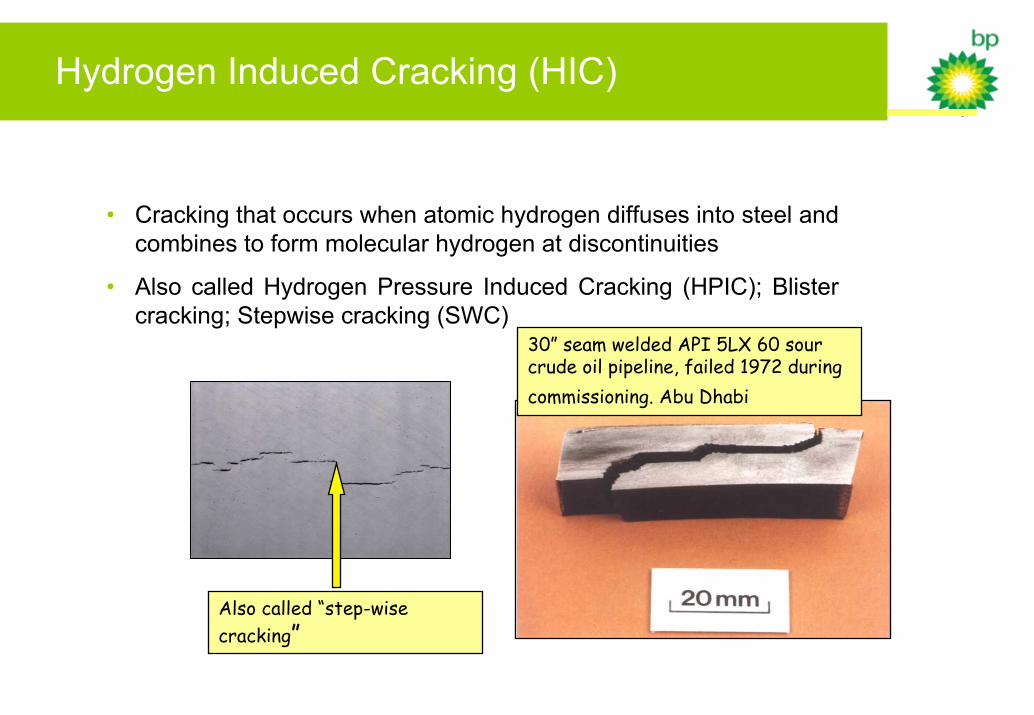
Hydrogen Induced Cracking (HIC)
• Cracking that occurs when atomic hydrogen diffuses into steel and combines to form molecular hydrogen at discontinuities
• Also called Hydrogen Pressure Induced Cracking (HPIC); Blister cracking; Stepwise cracking (SWC)
30” seam welded API 5LX 60 sour crude oil pipeline, failed 1972 during commissioning. Abu Dhabi
Also called “step-wise cracking”

HIC and Related Mechanisms in ISO15156/NACE HIC and Related Mechanisms in ISO15156/NACE MRMR--01750175
““The equipment user shall consider HIC/SWC The equipment user shall consider HIC/SWC as defined in ISO 15156as defined in ISO 15156--1/NACE MR1/NACE MR--0175 0175 when evaluating flatwhen evaluating flat--rolled carbon steel rolled carbon steel products for sour service environments products for sour service environments containing even trace amounts of Hcontaining even trace amounts of H22SS””

Preliminary proposal for HIC severity regions
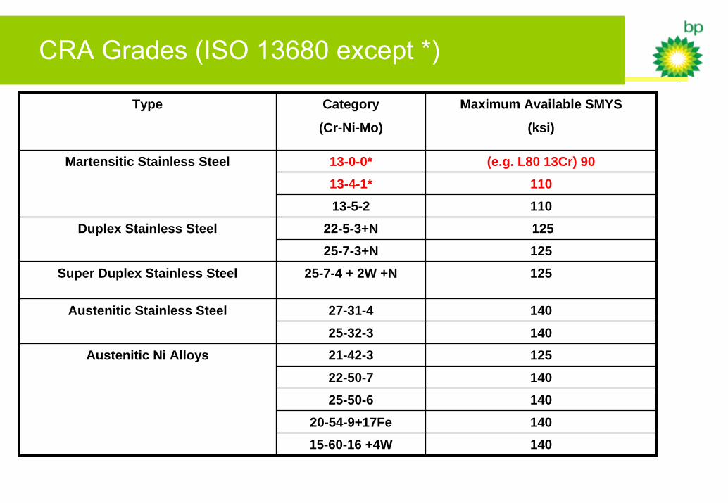
CRA Grades (ISO 13680 except *)
Type Category
(Cr-Ni-Mo)
Maximum Available SMYS
(ksi)
13-0-0* (e.g. L80 13Cr) 90
25-7-3+N 125
27-31-4 140
21-42-3 125
25-50-6 14020-54-9+17Fe 140
22-50-7 140
13-4-1* 110Martensitic Stainless Steel
13-5-2 11022-5-3+N 125
Super Duplex Stainless Steel 25-7-4 + 2W +N 125
Austenitic Stainless Steel25-32-3 140
Austenitic Ni Alloys
15-60-16 +4W 140
Duplex Stainless Steel
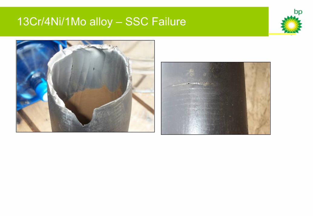
13Cr/4Ni/1Mo alloy – SSC Failure

SSC Failure of Downhole Tubular String
• HP/HT Gas Producer – 45mmscf/d, 50ppm H2S and 8.7mol%CO2. (0.5psia H2S, pH 3.5).
• Completed with a mixture of L80-13Cr & CR13 95ksi 13/4/1 tubing.• Packerless completion allowed produced fluid to contact tubing OD.• Tubing failed via SSC at localised sites of cold work on the OD (slip and
tong marks).• Gas, water and sand flowed from the tubing bore to the annulus,
resulting in significant erosion of both the tubing and casing.

Domain Diagram for Super 13Cr
pH
3.5
4.5
5.5
0.001 0.01 0.1 1.0pH2S (bara)
Domain Diagram For The Sulphide Stress Cracking Limits
Of 95ksi Super 13Cr Alloys In High Chloride (120,000 ppm Cl-) Waters
UNACCEPTABLE
ACCEPTABLE
0.03bara
FURTHER ASSESSMENT REQUIRED
pH
3.5
4.5
5.5
0.001 0.01 0.1 1.0pH2S (bara)
Domain Diagram For The Sulphide Stress Cracking Limits
Of 95ksi Super 13Cr Alloys In High Chloride (120,000 ppm Cl-) Waters
UNACCEPTABLE
ACCEPTABLE
0.03bara
FURTHER ASSESSMENT REQUIRED

Stress Corrosion Cracking (SCC)
• In the context of this talk relates to the SCC mechanisms that are associated with ‘active path dissolution’ mechanisms (e.g. chloride SCC) and not hydrogen-related mechanisms already covered (SSC, HIC, etc.)
• As such the focus is mainly corrosion-resistant alloys such as austenitic stainless steels (e.g. AISI 316), duplex stainless steels (mixed mode mechanism or CSC) and some nickel alloys (e.g. alloy 825)
• Developing domain diagrams for welded constructions (flowlines, manifolds, piping,vessels, etc.) similar to those already developed for OCTG

Domain diagrams for CRA flowlines and risers
pH
Partial Pressure H2S
Decrease chloride, temperature?
Increase chloride, temperature?
No cracking
Cracking

Effect of welding?
pH
Partial Pressure H2S

Cracking of duplex stainless steel

SSC Domain for 25Cr Duplex Stainless Steel (125ksi SMYS)<120,000 ppm Cl
pH
Partial pressure of H2S (bara)
Acceptable
Unacceptable
0.25 bara
0.5 bara
Areas of active research
• Effect of environmental conditions on cracking of CRAs
− Chloride
− Temperature
− pH
− H2S
• Effect of material processing on cracking
− Welding
− Plastic strain

H2S Cracking (SSC, SCC and HIC)
Thank YouForYour
Attention!

SOHIC
3.5mm
SOHIC
• Current Test Methods
− NACE TM0103 – Plate steels
− OTI 95 635 – Linepipe
• No universally accepted test method available
• Bodycote/TWI/Force JIP
− Aim – To develop a simple go/no go SOHIC test method for pressure vessel steels and line pipe

SOHIC
• SOHIC testing requires further development
− JIP Test Method (Test Method imposes simultaneous twisting and bending on a flat specimen to generate triaxial stress)
− Methods for assessing fittings
• Appropriate test methods need to be applied
• Test techniques need to be realistic such that good materials are accepted and poor ones rejected