Operator’s & Parts Manual - Wylie€¦ · Operator’s & Parts Manual ... for defective goods...
34
Operator’s & Parts Manual “Defender” 3 Pt Sprayer LGS-50 Trailer Sprayer Utility Skid Sprayer Deluxe Lawn & Garden Trailer Sprayer Printed In The USA — Specifications & Design Subject To Change Without Notice! 5-1-15 03-15R3
-
Upload
phungquynh -
Category
Documents
-
view
221 -
download
0
Transcript of Operator’s & Parts Manual - Wylie€¦ · Operator’s & Parts Manual ... for defective goods...

Operator’s & Parts Manual
“Defender” 3 Pt SprayerLGS-50 Trailer SprayerUtility Skid SprayerDeluxe Lawn & Garden Trailer Sprayer
Printed In The USA — Specifications & Design Subject To Change Without Notice! 5-1-15 03-15R3

This is a limited warranty. It covers products manufactured by WYLIE Mfg. Co. The Warrantor is WYLIE Mfg. Co., 702 E. 40th St., Lubbock, Texas, 79404, USA. The duration of the warranty for WYLIE manufactured equipment and products (excluding polyethylene tanks) is for one year from date of delivery to the carrier. The Warrantor warrants to the Buyer that the product(s) sold hereunder are free from defects to material and workmanship, under normal use and service, in the hands of the original buyer.
If goods are defective, the defective goods will be replaced with identical goods. If identical goods are not available, the Buyer may elect to receive a refund of the purchase price for the defective goods, or the Buyer may order similar goods. The damage for defective goods shall not exceed the purchase price of the defective goods. No allowance shall be made for labor or expense or repairing goods without prior approval in writing by the Warrantor. The Buyer’s remedy under this warranty does not include incidental or consequential damages.
For products not manufactured by the Warrantor, the Warrantor warrants these products to the extent of the warranties of their respective manufactures. There are no warranties which extend beyond this limited warranty, including the implied warranty of merchantability. Dealers or representatives shall not make any representation in regard to particular goods except as authorized by the Warrantor through a written warranty accompanying those particular goods.
WYLIE Mfg. Co., and its divisions, “Wylie Spray Centers,” in each location, requires as a condition of sale and coverage by its LIMITED WARRANTY that all equipment sold by it be used in accordance with the instructions and specifications of the Warrantor. This requirement is in addition to the LIMITED WARRANTY.
Polyethylene and fiberglass tanks – These tanks are warranted for the storage and transport of water, herbicide solutions (on farm), liquid fertilizer and liquid feed. Such tanks should not be used for the storage of any bulk herbicide (undiluted). Any such use will render this warranty void.
In addition, the Warrantor makes no warranty with regard to bulkhead tank fittings used in connection with tanks containing bulk herbicides and the use of any such fittings sold by the Warrantor or any WYLIE dealer in connection with tanks containing bulk herbicides is improper.
Chemical Incompatibility – The Warrantor does not make any recommendations or warranties regarding chemical compatibility. WYLIE shall not be liable for any damages due to chemical incompatibility, and any Buyer or user should rely solely on written information furnished by the chemical manufacturer regarding chemical compatibility.
No employee of WYLIE Mfg. Co., or its representatives, agents or dealers, is authorized to vary the terms of this limited warranty.
This equipment was carefully designed and manufactured to give you dependable service. To insure efficient operation of this equipment, please read this operator’s manual carefully. Check each item and acquaint yourself with the adjustments required to maintain optimum performance and operation. Remember, this equipment’s performance depends on how you operate and care for it!
At the end of each season, thoroughly clean and inspect your equipment. Preventive maintenance saves time and pays dividends. Your nearest Wylie Spray Center has original equipment parts which assure proper fit and best performance. Record your equipment’s model and serial numbers and the date you purchased this equipment in the space below. Have this information available when you order parts or attachments.
Model Number:
Serial Number:
Date Purchased:
A Message To The Owner And Operator
Limited Warranty
Disclaimer of Warranty
Warranty Information

Wylie Manufacturing Company702 E. 40th St.Lubbock, TX 79404Ph. 888-788-7753
“Defender” 3 Pt. SprayersLGS-50 Trailer Sprayer
Date of Purchase
Model Number
Tank Serial Number
Frame Serial Number
Pump Model
Wylie Invoice Number
Owner’s Name
Address
City State Zip
Phone
Dealer
Owner’s Signature
Must be returned within 10 days to validate the warranty.
Owner Registration
-- Or Register Online -- Go to: www.wyliesprayers.com
Utility Skid SprayerDeluxe Lawn & Garden Trailer Sprayer
Type of Applicator:
Trees Pasture
Crops Lawn/ Garden Spot Other

.
1
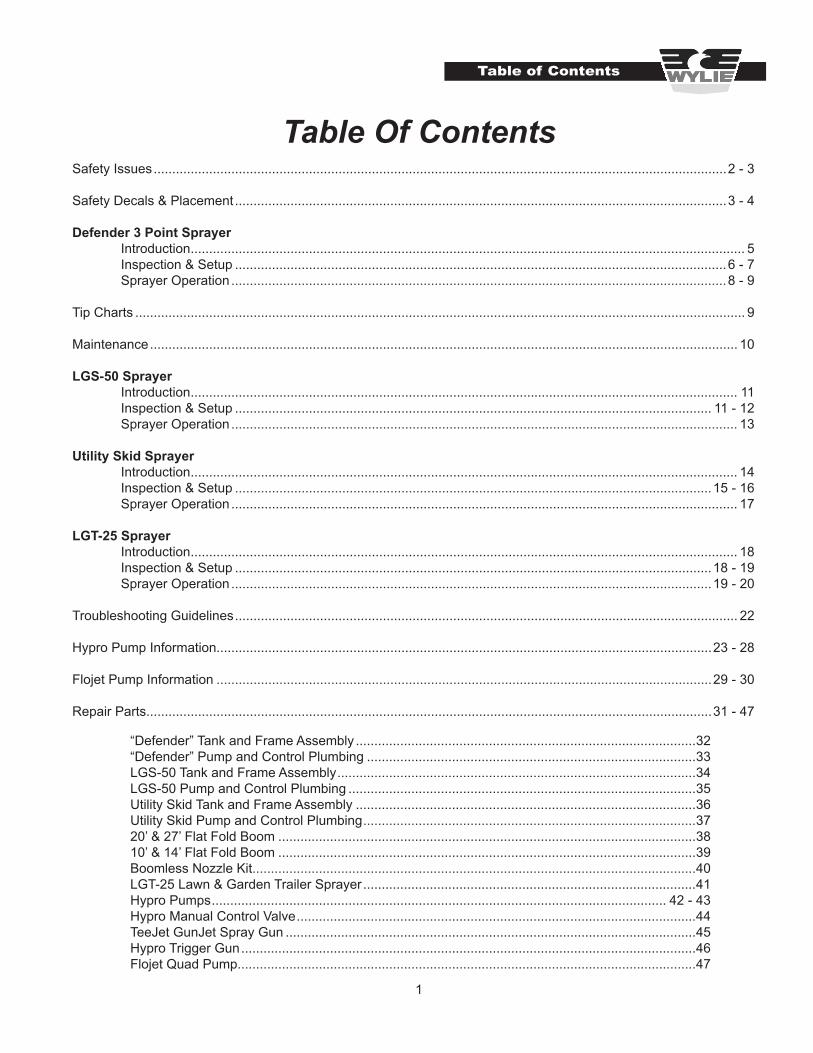
Table of Contents
Table Of ContentsSafety Issues ...........................................................................................................................................................2 - 3
Safety Decals & Placement .....................................................................................................................................3 - 4
Defender 3 Point Sprayer Introduction ...................................................................................................................................................... 5 Inspection & Setup .....................................................................................................................................6 - 7 Sprayer Operation ......................................................................................................................................8 - 9
Tip Charts ..................................................................................................................................................................... 9
Maintenance ............................................................................................................................................................... 10
LGS-50 Sprayer Introduction .................................................................................................................................................... 11 Inspection & Setup ................................................................................................................................. 11 - 12 Sprayer Operation ......................................................................................................................................... 13
Utility Skid Sprayer Introduction .................................................................................................................................................... 14 Inspection & Setup .................................................................................................................................15 - 16 Sprayer Operation ......................................................................................................................................... 17
LGT-25 Sprayer Introduction .................................................................................................................................................... 18 Inspection & Setup .................................................................................................................................18 - 19 Sprayer Operation ..................................................................................................................................19 - 20
Troubleshooting Guidelines ........................................................................................................................................ 22
Hypro Pump Information......................................................................................................................................23 - 28
Flojet Pump Information ......................................................................................................................................29 - 30
Repair Parts.........................................................................................................................................................31 - 47
“Defender” Tank and Frame Assembly ............................................................................................32“Defender” Pump and Control Plumbing .........................................................................................33LGS-50 Tank and Frame Assembly .................................................................................................34LGS-50 Pump and Control Plumbing ..............................................................................................35Utility Skid Tank and Frame Assembly ............................................................................................36Utility Skid Pump and Control Plumbing ..........................................................................................3720’ & 27’ Flat Fold Boom .................................................................................................................3810’ & 14’ Flat Fold Boom .................................................................................................................39Boomless Nozzle Kit........................................................................................................................40LGT-25 Lawn & Garden Trailer Sprayer ..........................................................................................41Hypro Pumps ........................................................................................................................... 42 - 43Hypro Manual Control Valve ............................................................................................................44TeeJet GunJet Spray Gun ...............................................................................................................45Hypro Trigger Gun ...........................................................................................................................46Flojet Quad Pump............................................................................................................................47
2
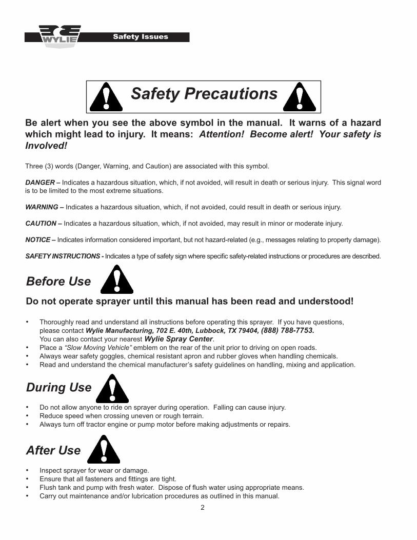
After Use• Inspect sprayer for wear or damage.• Ensure that all fasteners and fittings are tight.• Flush tank and pump with fresh water. Dispose of flush water using appropriate means.• Carry out maintenance and/or lubrication procedures as outlined in this manual.
Safety Issues
Safety PrecautionsBe alert when you see the above symbol in the manual. It warns of a hazard which might lead to injury. It means: Attention! Become alert! Your safety is Involved!
Three (3) words (Danger, Warning, and Caution) are associated with this symbol.
DANGER – Indicates a hazardous situation, which, if not avoided, will result in death or serious injury. This signal word is to be limited to the most extreme situations.
WARNING – Indicates a hazardous situation, which, if not avoided, could result in death or serious injury.
CAUTION – Indicates a hazardous situation, which, if not avoided, may result in minor or moderate injury.
NOTICE – Indicates information considered important, but not hazard-related (e.g., messages relating to property damage).
SAFETY INSTRUCTIONS - Indicates a type of safety sign where specific safety-related instructions or procedures are described.
Before UseDo not operate sprayer until this manual has been read and understood!
• Thoroughly read and understand all instructions before operating this sprayer. If you have questions, please contact Wylie Manufacturing, 702 E. 40th, Lubbock, TX 79404, (888) 788-7753. You can also contact your nearest Wylie Spray Center.• Place a “Slow Moving Vehicle” emblem on the rear of the unit prior to driving on open roads.• Always wear safety goggles, chemical resistant apron and rubber gloves when handling chemicals.• Read and understand the chemical manufacturer’s safety guidelines on handling, mixing and application.
During Use• Do not allow anyone to ride on sprayer during operation. Falling can cause injury.• Reduce speed when crossing uneven or rough terrain.• Always turn off tractor engine or pump motor before making adjustments or repairs.
3
Safety Issues
Always• Keep hands, feet and clothing away from moving parts.• Wear protective clothing and gloves when working with chemicals.
Operator’s Instructions• Securely fasten seat belt if tractor is equipped with a Roll Over Protection System (ROPS).• When possible, avoid operating the tractor near ditches, embankments and holes.• Reduce speed when turning, crossing slopes and on rough, slick or muddy surfaces.• Be aware of where you are going at all times; especially at row ends, roads and around trees.• Do not permit others to ride.• Operate tractor smoothly – no jerky turns, starts and stops.• Hitch only to the drawbar and hitch points recommended by the tractor manufacturer.• When tractor is idle, engage brakes and park lock securely.• Limit transport speed to 25 mph.
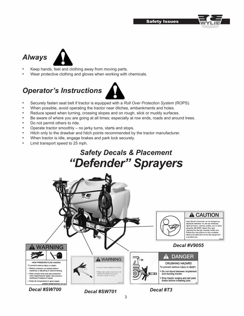
Safety Decals & Placement“Defender” Sprayers
Decal #V9055
Decal #SW700 Decal #T3Decal #SW701

4
Safety Decals & Placement
Safety Issues
Decal #V9055Decal #SW700
LGS-50, Utility Skid Sprayers
Decal #V9020
Decal #SW701
Decal #SW701
5
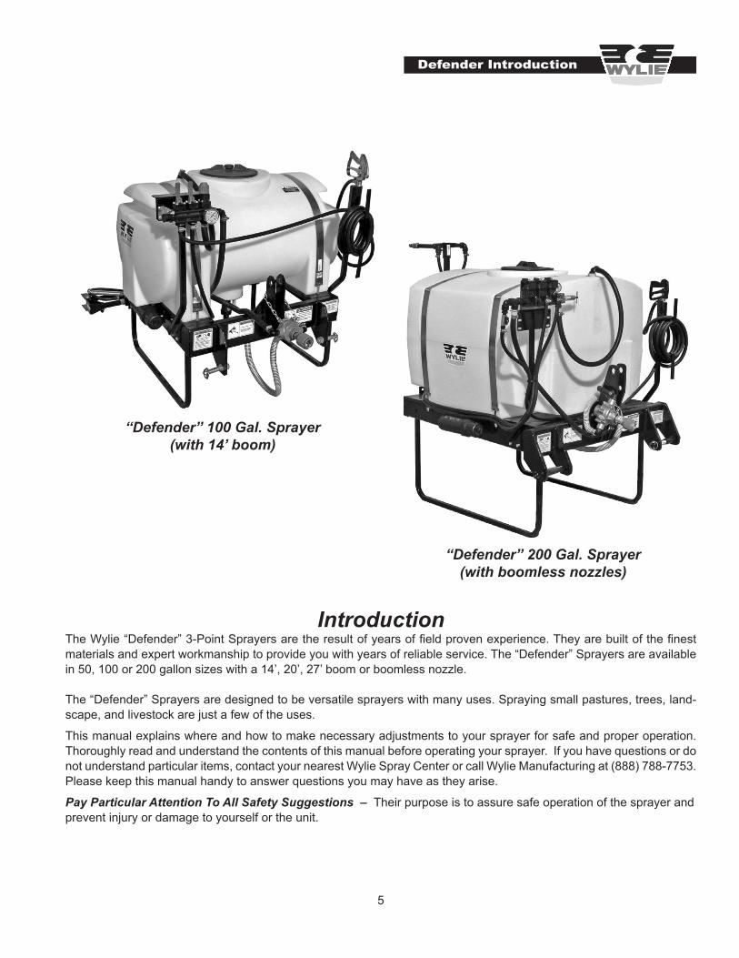
The Wylie “Defender” 3-Point Sprayers are the result of years of field proven experience. They are built of the finest materials and expert workmanship to provide you with years of reliable service. The “Defender” Sprayers are available in 50, 100 or 200 gallon sizes with a 14’, 20’, 27’ boom or boomless nozzle.
The “Defender” Sprayers are designed to be versatile sprayers with many uses. Spraying small pastures, trees, land-scape, and livestock are just a few of the uses.
This manual explains where and how to make necessary adjustments to your sprayer for safe and proper operation. Thoroughly read and understand the contents of this manual before operating your sprayer. If you have questions or do not understand particular items, contact your nearest Wylie Spray Center or call Wylie Manufacturing at (888) 788-7753. Please keep this manual handy to answer questions you may have as they arise.
Pay Particular Attention To All Safety Suggestions – Their purpose is to assure safe operation of the sprayer and prevent injury or damage to yourself or the unit.
Defender Introduction
Introduction
“Defender” 100 Gal. Sprayer(with 14’ boom)
“Defender” 200 Gal. Sprayer(with boomless nozzles)
6
Defender Insp & Setup
Defender Inspection & SetupYour Wylie “Defender” 3 Point Sprayer was manufactured to the highest standards of quality. It is necessary though, to check to make sure that nothing was damaged during shipping. Check bolts and fasteners for tightness. Check the pump and plumbing for any signs of damage.
”Defender” Sprayer Inspection & Setup
Your Wylie “Defender” sprayer was completely assembled and should not need any additional assembly before use. However, if the sprayer was motor freighted directly to you, minor assembly will be required.
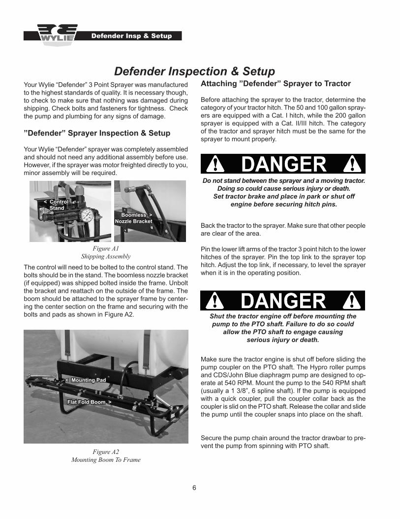
The control will need to be bolted to the control stand. The bolts should be in the stand. The boomless nozzle bracket (if equipped) was shipped bolted inside the frame. Unbolt the bracket and reattach on the outside of the frame. The boom should be attached to the sprayer frame by center-ing the center section on the frame and securing with the bolts and pads as shown in Figure A2.
Attaching ”Defender” Sprayer to Tractor
Before attaching the sprayer to the tractor, determine the category of your tractor hitch. The 50 and 100 gallon spray-ers are equipped with a Cat. I hitch, while the 200 gallon sprayer is equipped with a Cat. II/III hitch. The category of the tractor and sprayer hitch must be the same for the sprayer to mount properly.
Back the tractor to the sprayer. Make sure that other people are clear of the area.
Pin the lower lift arms of the tractor 3 point hitch to the lower hitches of the sprayer. Pin the top link to the sprayer top hitch. Adjust the top link, if necessary, to level the sprayer when it is in the operating position.
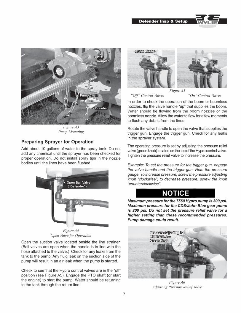
Make sure the tractor engine is shut off before sliding the pump coupler on the PTO shaft. The Hypro roller pumps and CDS/John Blue diaphragm pump are designed to op-erate at 540 RPM. Mount the pump to the 540 RPM shaft (usually a 1 3/8”, 6 spline shaft). If the pump is equipped with a quick coupler, pull the coupler collar back as the coupler is slid on the PTO shaft. Release the collar and slide the pump until the coupler snaps into place on the shaft.
Secure the pump chain around the tractor drawbar to pre-vent the pump from spinning with PTO shaft.
Figure A1 Shipping Assembly
Do not stand between the sprayer and a moving tractor. Doing so could cause serious injury or death.
Set tractor brake and place in park or shut off engine before securing hitch pins.
Shut the tractor engine off before mounting the pump to the PTO shaft. Failure to do so could
allow the PTO shaft to engage causing serious injury or death.
Figure A2 Mounting Boom To Frame
Boomless > Nozzle Bracket
< Control Stand
Flat Fold Boom >
< Mounting Pad
7
Preparing Sprayer for OperationAdd about 10 gallons of water to the spray tank. Do not add any chemical until the sprayer has been checked for proper operation. Do not install spray tips in the nozzle bodies until the lines have been flushed.
Open the suction valve located beside the line strainer. (Ball valves are open when the handle is in line with the hose attached to the valve.) Check for any leaks from the tank to the pump. Any fluid leak on the suction side of the pump will result in an air leak when the pump is started.
Check to see that the Hypro control valves are in the “off” position (see Figure A5). Engage the PTO shaft (or start the engine) to start the pump. Water should be returning to the tank through the return line.
In order to check the operation of the boom or boomless nozzles, flip the valve handle “up” that supplies the boom. Water should be flowing from the boom nozzles or the boomless nozzle. Allow the water to flow for a few moments to flush any debris from the lines.
Rotate the valve handle to open the valve that supplies the trigger gun. Engage the trigger gun. Check for any leaks in the sprayer system.
The operating pressure is set by adjusting the pressure relief valve (green knob) located on the top of the Hypro control valve. Tighten the pressure relief valve to increase the pressure.
Example: To set the pressure for the trigger gun, engage the valve handle and the trigger gun. Note the pressure gauge. To increase pressure, screw the pressure adjusting knob “clockwise”; to decrease pressure, screw the knob “counterclockwise”.
Maximum pressure for the 7560 Hypro pump is 300 psi. Maximum pressure for the CDS/John Blue gear pump is 200 psi. Do not set the pressure relief valve for a higher setting than these recommended pressures. Pump damage could result.
Figure A3 Pump Mounting
< PTO Coupler
< Pump Chain
< Drawbar
Figure A4Open Valve for Operation
< Open Ball Valve(“Defender”)
Figure A5 “Off” Control Valves “On” Control Valves
Green Knob >
Defender Insp & Setup
Figure A6Adjusting Pressure Relief Valve
Pressure Adjusting >Relief Valve --Green Knob
8
Add the desired amount of water or fertilizer to the sprayer tank. Add the correct amount of chemical to the sprayer tank. Read the instructions on the chemical container for details regarding the proper amount of chemical to add.
Assure the control valve is “off” before starting the pump. Engage the pump and let the pump run for a few minutes to thoroughly mix the solution.
Some “Defender” sprayers are equipped with an agitator. The agitator valve should be opened to keep chemicals in proper suspension. Turn the valve parallel with the valve to open the agitator. If the boom or gun does not come up to proper operating pressure after adjusting the pressure regulating knob (green knob), partially close the agitator valve to raise the pressure.
Figure A7Installing Tips and Screens
Figure A8Opening Agitator Valve
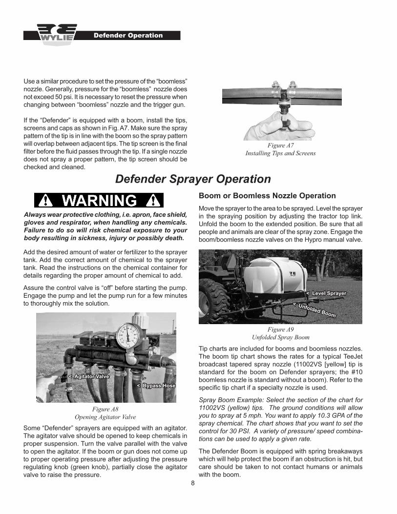
Defender Sprayer OperationBoom or Boomless Nozzle OperationMove the sprayer to the area to be sprayed. Level the sprayer in the spraying position by adjusting the tractor top link. Unfold the boom to the extended position. Be sure that all people and animals are clear of the spray zone. Engage the boom/boomless nozzle valves on the Hypro manual valve.
Tip charts are included for booms and boomless nozzles. The boom tip chart shows the rates for a typical TeeJet broadcast tapered spray nozzle (11002VS [yellow] tip is standard for the boom on Defender sprayers; the #10 boomless nozzle is standard without a boom). Refer to the specific tip chart if a specialty nozzle is used.
Spray Boom Example: Select the section of the chart for 11002VS (yellow) tips. The ground conditions will allow you to spray at 5 mph. You want to apply 10.3 GPA of the spray chemical. The chart shows that you want to set the control for 30 PSI. A variety of pressure/ speed combina-tions can be used to apply a given rate.
The Defender Boom is equipped with spring breakaways which will help protect the boom if an obstruction is hit, but care should be taken to not contact humans or animals with the boom.
Defender Operation
Use a similar procedure to set the pressure of the “boomless” nozzle. Generally, pressure for the “boomless” nozzle does not exceed 50 psi. It is necessary to reset the pressure when changing between “boomless” nozzle and the trigger gun.
If the “Defender” is equipped with a boom, install the tips, screens and caps as shown in Fig. A7. Make sure the spray pattern of the tip is in line with the boom so the spray pattern will overlap between adjacent tips. The tip screen is the final filter before the fluid passes through the tip. If a single nozzle does not spray a proper pattern, the tip screen should be checked and cleaned.
< Agitator Valve
< Level Sprayer
< Unfolded Boom
Figure A9Unfolded Spray Boom
Always wear protective clothing, i.e. apron, face shield, gloves and respirator, when handling any chemicals. Failure to do so will risk chemical exposure to your body resulting in sickness, injury or possibly death.
< Bypass Hose

9
Tip Charts
Single Boomless Nozzle Chart
Boom Nozzle Chart
4.0 4.5 5.0 5.5 6.0 6.5 7.0 7.5 8.0
psi gpm20 0.07 5.3 4.7 4.2 3.8 3.5 3.2 3.0 2.8 2.630 0.09 6.5 5.7 5.2 4.7 4.3 4.0 3.7 3.4 3.240 0.10 7.4 6.6 5.9 5.4 5.0 4.6 4.2 4.0 3.7
100 MESH 50 0.11 8.3 7.4 6.7 6.0 5.5 5.1 4.8 4.4 4.2ORANGE 60 0.12 9.1 8.1 7.2 6.6 6.0 5.6 5.2 4.8 4.5
20 0.11 7.9 7.0 6.3 5.7 5.2 4.8 4.5 4.2 3.930 0.13 9.7 8.6 7.7 7.0 6.4 5.9 5.5 5.1 4.840 0.15 11.1 9.9 8.9 8.1 7.4 6.9 6.4 5.9 5.6
100 MESH 50 0.17 12.5 11.1 10.0 9.1 8.3 7.7 7.1 6.7 6.2GREEN 60 0.18 13.7 12.1 10.9 9.9 9.1 8.4 7.8 7.3 6.8
20 0.14 10.5 9.3 8.4 7.6 7.0 6.4 6.0 5.6 5.230 0.17 12.8 11.4 10.3 9.3 8.6 7.9 7.3 6.9 6.440 0.20 14.9 13.2 11.9 10.8 9.9 9.1 8.5 7.9 7.4
50 MESH 50 0.22 16.6 14.8 13.3 12.1 11.1 10.2 9.5 8.9 8.3YELLOW 60 0.25 18.2 16.2 14.6 13.2 12.1 11.2 10.4 9.7 9.1
20 0.21 15.7 14.0 12.6 11.4 10.5 9.7 9.0 8.4 7.930 0.26 19.3 17.2 15.4 14.0 12.9 11.9 11.0 10.3 9.740 0.30 22.3 19.8 17.8 16.2 14.9 13.7 12.7 11.9 11.1
50 MESH 50 0.34 24.9 22.1 19.9 18.1 16.6 15.3 14.2 13.3 12.4BLUE 60 0.37 27.2 24.2 21.8 19.8 18.2 16.8 15.6 14.5 13.6
20 0.28 21.0 18.7 16.8 15.3 14.0 12.9 12.0 11.2 10.530 0.35 25.7 22.8 20.6 18.7 17.1 15.8 14.7 13.7 12.840 0.40 29.7 26.4 23.8 21.6 19.8 18.3 17.0 15.8 14.9
50 MESH 50 0.45 33.2 29.5 26.6 24.1 22.1 20.4 19.0 17.7 16.6RED 60 0.49 36.4 32.3 29.1 26.5 24.3 22.4 20.8 19.4 18.2
20 0.35 26.3 23.4 21.0 19.1 17.5 16.2 15.0 14.0 13.130 0.43 32.2 28.6 25.7 23.4 21.4 19.8 18.4 17.1 16.140 0.50 37.1 33.0 29.7 27.0 24.8 22.8 21.2 19.8 18.6
50 MESH 50 0.56 41.5 36.9 33.2 30.2 27.7 25.5 23.7 22.1 20.8BROWN 60 0.61 45.4 40.4 36.4 33.0 30.3 28.0 26.0 24.2 22.7
TP 110°/ 80° 20" TIP SPACINGALL VALUES BASED ON WATER FOR OTHER LIQUIDS
mph
8001VS 11001VS
80015VS 110015VS
8002VS 11002VS
8003VS 11003VS
8004VS 11004VS
8005VS 11005VS
Hand Spray Gun Operation
To operate the hand spray gun, unroll the hand spray gun hose from the hose wrap. With the boom control valves turned “off”, rotate the hand spray gun control valve “on”. With the hand spray gun pointed away from any person or body part, squeeze the trigger. Adjust the pressure regulat-ing knob (green knob) to set the desired pressure.
Do not point the spray hand gun toward any person or body part. The chemical and/or spray
pressure can cause serious or fatal injuries.
Dual Boomless Nozzle Chart

10
All Sprayers Maintenance
All Sprayers Maintenance
Line Strainer Cleaning
From time to time it may be necessary to clean the line strainer. The line strainer is located in the hose between the spray tank and the pump. With the tractor or engine turned off, close the ball valve beside the strainer. Unscrew the bowl from the strainer base. Remove and clean the screen. Check for any damage to the screen that would allow debris to get to the pump and nozzles. Empty and rinse the bowl. Replace the bowl and screen. Make sure that the gasket/o-ring that seals the bowl to the base is not lost when cleaning. Open the ball valve before starting the pump. Many strainers are equipped with a drain plug that can be removed to drain the suction lines (with ball valve closed) or the spray tank (with ball valve open).
Cleaning NozzlesWhile the line strainer usually keeps the system clean, it is possible for foreign matter to clog the trigger gun or nozzles.
Turn the tractor or engine off before cleaning any nozzles. Wear chemically resistant rubber gloves.
To clean the trigger gun nozzle, engage the trigger gun to relieve any pressure. Remove the cap at the end of the barrel to access the tip. The tip should be cleaned with a brush such as a TeeJet tip cleaning brush. Do not use a pocket knife, wire or screwdriver to clear the nozzle. The tip could be damaged, resulting in an improper spray pattern. In order to clean the “boomless” nozzle, remove the nozzle from the stand. Use compressed air to blow debris from the nozzle. Do not use pocket knives, wire or screwdrivers.
Clean the boom nozzles by removing the nozzle cap. Re-move the tip screen and clean it as needed. The tip should be cleaned with a brush such as a TeeJet tip cleaning brush. Do not use a pocket knife, wire or screwdriver to clear the nozzle. The tip could be damaged, resulting in an improper spray pattern.
Chemically resistant rubber gloves must be worn when cleaning the line strainer. Failure to do so
could result in chemical exposure causing serious injury.
End of Day ProcedureSome corrosive chemicals require the pump to be flushed with clean water to prevent pump damage. Add 5-10 gal-lons of clean water to an empty spray tank. Turn the pump on and apply this flush solution to a safe area.
Check the sprayer for any leaks or damaged parts. Repair or replace as necessary.
Operation during cold weather may require protecting the sprayer from freeze damage. See the next section for instructions.
End of Season ProcedureThoroughly flush the complete system with clean water. Flush the trigger gun as well as the boom nozzles. Dis-pose of the flush solution by spraying a safe area. Check the chemical container label for any special instructions.
To protect the sprayer from freezing, one of two procedures should be followed: draining the system or flushing with anti-freeze solution.
Draining the sprayer With the spray tank empty, remove the strainer bowl to drain water from the suction side of the pump. Some styles of pumps are equipped with a drain plug. Remove this plug to allow the pump to drain. If the sprayer is equipped with a roller pump, operate the pump for 3-5 seconds to purge any water from the pump. Lay the trigger hose out flat, open the control valve, lock the trigger gun open and allow the water to drain from the gun. Open other lines to allow any water to drain.
Flushing with anti-freezeAdd a few gallons of anti-freeze solution (such as camper trailer anti-freeze) to the spray tank. Start the pump and open the valves to flush both the trigger gun and boom. This procedure is the most complete way to protect the sprayer from freezing.
Cast iron roller pumps need the further protection of 30 wt. motor oil for lubrication. Add a small amount of oil to the suction side of the pump. Turn the pump several revolu-tions to apply a protective oil film inside the pump housing.

11
The Wylie LGS-50 Sprayer is built of the finest materials and expert workmanship to provide you with years of reliable service. The LGS-50F Sprayer features a 50 gallon spray tank with a 7’, 10’, 14’ boom or boomless nozzle and high flotation tires. An LGS-50 unit is also available with standard tires.
The LGS-50 Sprayer is designed to be a versatile sprayer with many uses. Spraying small pastures, trees, landscape, and gardens are just a few of the uses.
This manual explains where and how to make necessary adjustments to your sprayer for safe and proper operation. Thoroughly read and understand the contents of this manual before operating your sprayer. If you have questions or do not understand particular items, contact your nearest Wylie Spray Center or call Wylie Manufacturing at (888) 788-7753. Please keep this manual handy to answer questions you may have as they arise.
Pay Particular Attention To All Safety Suggestions – Their purpose is to assure safe operation of the sprayer and prevent injury or damage to yourself or the unit.
LGS-50 Introduction
Introduction
LGS-50F Sprayer(with 14’ boom)
Your Wylie LGS-50 Sprayer was manufactured to the high-est standards of quality. It is necessary though, to check to make sure that nothing was damaged during shipping. Check bolts and fasteners for tightness. Check the pump and plumbing for any signs of damage. The owner’s manual is stored in the manual tube. Read and understand the manual before operating the LGS-50 sprayer.
LGS-50 Sprayer Inspection & Setup
The LGS-50 trailer sprayer may require some minor as-sembly. If shipped via motor freight, the tongue, control stand and boom may be shipped strapped to the sprayer. Bolt the control stand to the frame and bolt the tongue to the control stand and frame as shown in Figure B1. Secure the controller to the stand bracket.
LGS-50 Inspection and Setup
Figure B1Tongue and Control Mounting
< Control Stand
< Controller
< Manual Tube
Tongue >
LGS-50F Sprayer(with 14’ boom)

12
Attach the flat fold boom to the mount bracket with the U-bolts at the desired height. Fit the supply hose to the “T” hosebarb and secure with a hose clamp.
Preparing Sprayer for OperationAdd about 10 gallons of water to the spray tank. Do not add any chemical until the sprayer has been checked for proper operation. Do not install spray tips in the nozzle bodies until the lines have been flushed.
Open the gate valve located beside the line strainer. Check for any leaks from the tank to the pump. Any fluid leak on the suction side of the pump will result in an air leak when the pump is started.
Check to see that the Hypro control valves are in the “off” position (see Figure B4). Start the engine to engage the pump. Water should be returning to the tank through the return line.
In order to check the operation of the boom or boomless nozzles, rotate the valve handle “up” that supplies the boom. Water should be flowing from the boom nozzles or the boomless nozzle. Allow the water to flow for a few moments to flush any debris from the lines.
Turn the boom off and rotate the valve handle of the valve that supplies the trigger gun. Engage the trigger gun. Check for any leaks in the sprayer gun system.
The operating pressure is set by adjusting the pressure relief valve (green knob) located on the top of the Hypro control valve. Tighten the pressure relief valve to increase the pressure.
Example: To set the pressure for the trigger gun, engage the valve handle and the trigger gun. Note the pressure gauge. To increase pressure, screw the pressure adjusting knob “clockwise”; to decrease pressure, screw the knob “counterclockwise”.
Note: Maximum pressure for the Hypro roller pump is 150 psi.
Install the tips, screens and caps as shown in Fig. B6. Make sure the spray pattern of the tip is in line with the boom so the spray pattern will overlap between adjacent tips. The tip screen is the final filter before the fluid passes through the tip. If a single nozzle does not spray a proper pattern, the tip screen should be checked and cleaned.
Figure B2Boom Mounting
LGS-50 Insp. & Setup
Tee Hosebarb >
Boom Mount >
< Open Gate Valve
Figure B3Open Gate Valve
Figure B4 “Off” Control Valves “On” Control Valves
Green Knob >
Figure B5 Adjusting Pressure Relief Valve
Pressure Adjusting >Relief Valve --Green Knob
Always wear protective clothing, i.e. apron, face shield, gloves and respirator, when handling any chemicals. Failure to do so will risk chemical exposure to your body resulting in sickness, injury or possibly death.

13
Add the desired amount of water or fertilizer to the sprayer tank. Add the correct amount of chemical to the sprayer tank. Read the instructions on the chemical container for details regarding the proper amount of chemical to add.
The LGS-50 sprayer may be equipped with an agitator. The agitator valve should be opened to keep chemicals in proper suspension. Turn the valve parallel with the valve to open the agitator. If the boom or gun does not come up to proper operating pressure, partially close the agitator valve to raise the pressure.
Assure the control valve is “off” before starting the pump. Engage the pump and let the pump run for a few minutes to thoroughly mix the solution.
Boom OperationMove the sprayer to the area to be sprayed. Unfold the boom to the extended position. Be sure that all people and animals are clear of the spray zone. Engage the boom/boomless nozzle valves on the Hypro manual valve.
LGS-50 Operation
LGS-50 Operation
Figure B6Installing Tips and Screens
Figure B7Opening Agitator Valve (if equipped)
< Agitator Valve
Tip charts are included for booms on Page 9. The boom tip chart shows the rates for a typical TeeJet broadcast tapered spray nozzle (11002VS [yellow] tip is standard for the boom on LGS-50 sprayers). Refer to the specific tip chart if a specialty nozzle is used.
Spray Boom Example: Select the section of the chart for 11002VS (yellow) tips. The ground conditions will allow you to spray at 5 mph. You want to apply 10.3 GPA of the spray chemical. The chart shows that you want to set the control for 30 PSI. A variety of pressure/ speed combina-tions can be used to apply a given rate.
Contact the Wylie Spray Center if a different size or style of nozzle is needed.
The LGS-50 Boom is equipped with spring breakaways which will help protect the boom if an obstruction is hit, but care should be taken to not contact humans or animals with the boom. Hand Spray Gun Operation
To operate the hand spray gun, unroll the hand spray gun hose from the hose wrap. With the boom control valve turned “off”, rotate the hand spray gun control valve “on”. With the hand spray gun pointed away from any person or body part, squeeze the trigger. Adjust the pressure regulat-ing knob (green knob) to set the desired pressure.
See Page 10 for maintenance and end of day/season procedure.
Figure B8Unfolded Spray Boom
Do not point the spray hand gun toward any person or body part. The chemical and/or spray
pressure can cause serious or fatal injuries.
< Bypass Hose
Spring Breakaway
14
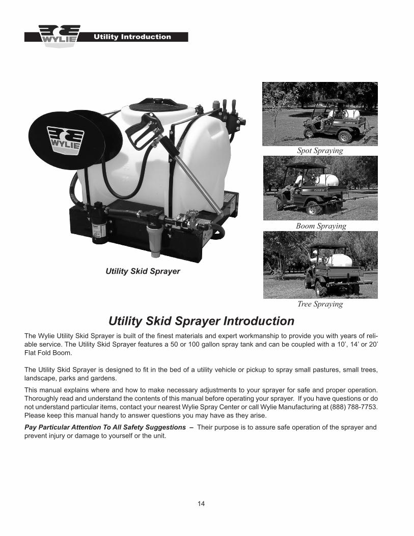
The Wylie Utility Skid Sprayer is built of the finest materials and expert workmanship to provide you with years of reli-able service. The Utility Skid Sprayer features a 50 or 100 gallon spray tank and can be coupled with a 10’, 14’ or 20’ Flat Fold Boom.
The Utility Skid Sprayer is designed to fit in the bed of a utility vehicle or pickup to spray small pastures, small trees, landscape, parks and gardens.
This manual explains where and how to make necessary adjustments to your sprayer for safe and proper operation. Thoroughly read and understand the contents of this manual before operating your sprayer. If you have questions or do not understand particular items, contact your nearest Wylie Spray Center or call Wylie Manufacturing at (888) 788-7753. Please keep this manual handy to answer questions you may have as they arise.
Pay Particular Attention To All Safety Suggestions – Their purpose is to assure safe operation of the sprayer and prevent injury or damage to yourself or the unit.
Utility Introduction
Utility Skid Sprayer Introduction
Utility Skid Sprayer
Spot Spraying
Boom Spraying
Tree Spraying

15
Connecting 12 Volt Pump to Power
The 12 volt Flojet Quad pump is an on-demand pump that will automatically shut off when the discharge valve is closed. The pump can be wired permanently with a toggle switch to turn power on or off to the pump (red wire is posi-tive (+), black wire is negative (-).)
Installing the Flat Fold Boom
The Utility Skid may be equipped with an optional Flat Fold boom that mounts in the receiver hitch of a pickup or utility vehicle.
Insert the boom mount into the vehicle receiver hitch, then slide the boom over the boom mount and pin at the desired spraying height. Tighten the spreader bolt on the boom mount to remove any slack inside the receiver hitch. Tighten the jam nut.
Fit the supply hose to the “T” hosebarb and secure with a hose clamp.
Your Wylie Utility Skid Sprayer was manufactured to the highest standards of quality. It is necessary though, to check to make sure that nothing was damaged during shipping. Check bolts and fasteners for tightness. Check the pump and plumbing for any signs of damage.
Utility Skid Sprayer Inspection & Setup
Your Wylie Utility Skid Sprayer was completely assembled and should not need any additional assembly before use.
The 50 or 100 gallon Utility Skid Sprayer can be mounted in a pickup or utility vehicle and is equipped with “L” bracket tiedowns. The four tiedown brackets and hardware are bagged and shipped inside the tank.
Set the skid in the desired location in the bed of the vehicle, mark and drill ½” holes in the bed and the skid frame. Install and tighten the nuts and bolts.
Utility Skid Sprayer Inspection and Setup
Figure C2 Utility Skid Tiedown
< Tiedown Bracket
Figure C4Flat Fold Boom Receiver Hitch Mounting
< Red (Positive +) Wire
Black (
Negati
ve -)
Wire > < Pressure Switch
< Receiver Hitch
< Boom Mount
Boom Mount Tube >
Figure C312 Volt Pump Wiring
Figure C1Utility Skid Sprayer
< “T” Hosebarb
< ½” Supply Hose
Utility Inspection & Setup

16
Preparing Sprayer for OperationAdd about 10 gallons of water to the spray tank. Do not add any chemical until the sprayer has been checked for proper operation. Do not install spray tips in the nozzle bodies on the boom until the lines have been flushed.
Open the gate valve located beside the line strainer. Check for any leaks from the tank to the pump. Any fluid leak on the suction side of the pump will result in an air leak when the pump is started.
Check to see that the Hypro control valves are in the “off” position (see Figure C6). Flip the toggle switch “on”. The pump will operate until the on-demand switch turns the pump off at 35 psi.
The operating pressure is set by adjusting the pressure relief valve (green knob) located on the top of the Hypro control valve. Tighten the pressure relief valve to increase the pressure.
Example: To set the pressure for the trigger gun, engage the valve handle and the trigger gun. Note the pressure gauge. To increase pressure, screw the pressure adjust-ing knob “in”; to decrease pressure, screw the knob “out”.
Utility Inspection & Setup
Note: The pressure for the 12 volt Quad pump can only be adjusted up to the preset pressure (35 psi) of the pump switch.
In order to check the operation of the optional Flat Fold boom rotate the valve handle “up” that supplies the boom. Water should be flowing from the boom nozzles. Allow the water to flow for a few moments to flush any debris from the lines.
Install the tips, screens and caps as shown in Fig. C8. Make sure the spray pattern of the tip is in line with the boom so the spray pattern will overlap between adjacent tips. The tip screen is the final filter before the fluid passes through the tip. If a single nozzle does not spray a proper pattern, the tip screen should be checked and cleaned.
The operating pressure is set by adjusting the pressure relief valve (green knob) located on the top of the Hypro control valve as shown in Fig. C7. Tighten the pressure relief valve to increase the pressure.
Figure C6 “Off” Control Valves “On” Control Valves
Green Knob >
Figure C7 Adjusting Pressure Relief Valve
Pressure Adjusting >Relief Valve --Green Knob
Figure C5 Open Gate Valve
Gate Valve >
Figure C8Installing Tips and Screens
17
Add the desired amount of water or fertilizer to the sprayer tank. Add the correct amount of chemical to the sprayer tank. Read the instructions on the chemical container for details regarding the proper amount of chemical to add.
Hand Spray Gun Operation
To operate the hand spray gun, unroll the hand spray gun hose from the hose wrap. With the boom control valve turned “off”, rotate the hand spray gun control valve “on”. With the hand spray gun pointed away from any person or body part, squeeze the trigger. Adjust the pressure regulat-ing knob (green knob) to set the desired pressure.
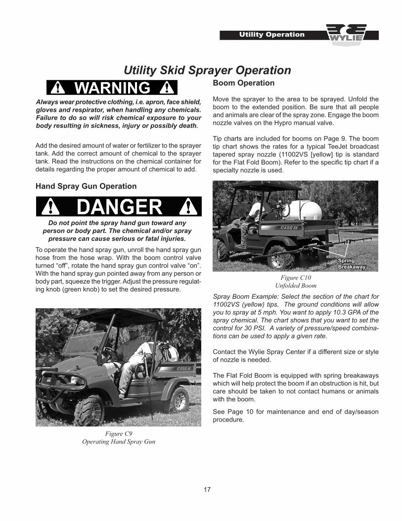
Utility Skid Sprayer OperationBoom Operation
Move the sprayer to the area to be sprayed. Unfold the boom to the extended position. Be sure that all people and animals are clear of the spray zone. Engage the boom nozzle valves on the Hypro manual valve.
Tip charts are included for booms on Page 9. The boom tip chart shows the rates for a typical TeeJet broadcast tapered spray nozzle (11002VS [yellow] tip is standard for the Flat Fold Boom). Refer to the specific tip chart if a specialty nozzle is used.
Spray Boom Example: Select the section of the chart for 11002VS (yellow) tips. The ground conditions will allow you to spray at 5 mph. You want to apply 10.3 GPA of the spray chemical. The chart shows that you want to set the control for 30 PSI. A variety of pressure/speed combina-tions can be used to apply a given rate.
Contact the Wylie Spray Center if a different size or style of nozzle is needed.
The Flat Fold Boom is equipped with spring breakaways which will help protect the boom if an obstruction is hit, but care should be taken to not contact humans or animals with the boom. See Page 10 for maintenance and end of day/season procedure.
Do not point the spray hand gun toward any person or body part. The chemical and/or spray
pressure can cause serious or fatal injuries.
Figure C10 Unfolded Boom
Figure C9Operating Hand Spray Gun
Utility Operation
Always wear protective clothing, i.e. apron, face shield, gloves and respirator, when handling any chemicals. Failure to do so will risk chemical exposure to your body resulting in sickness, injury or possibly death.
Spring Breakaway
18
L&G Introduction
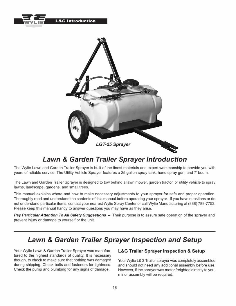
LGT-25 Sprayer
The Wylie Lawn and Garden Trailer Sprayer is built of the finest materials and expert workmanship to provide you with years of reliable service. The Utility Vehicle Sprayer features a 25 gallon spray tank, hand spray gun, and 7’ boom.
The Lawn and Garden Trailer Sprayer is designed to tow behind a lawn mower, garden tractor, or utility vehicle to spray lawns, landscape, gardens, and small trees.
This manual explains where and how to make necessary adjustments to your sprayer for safe and proper operation. Thoroughly read and understand the contents of this manual before operating your sprayer. If you have questions or do not understand particular items, contact your nearest Wylie Spray Center or call Wylie Manufacturing at (888) 788-7753. Please keep this manual handy to answer questions you may have as they arise.
Pay Particular Attention To All Safety Suggestions – Their purpose is to assure safe operation of the sprayer and prevent injury or damage to yourself or the unit.
Lawn & Garden Trailer Sprayer Introduction
Lawn & Garden Trailer Sprayer Inspection and SetupYour Wylie Lawn & Garden Trailer Sprayer was manufac-tured to the highest standards of quality. It is necessary though, to check to make sure that nothing was damaged during shipping. Check bolts and fasteners for tightness. Check the pump and plumbing for any signs of damage.
L&G Trailer Sprayer Inspection & Setup
Your Wylie L&G Trailer sprayer was completely assembled and should not need any additional assembly before use. However, if the sprayer was motor freighted directly to you, minor assembly will be required.
19
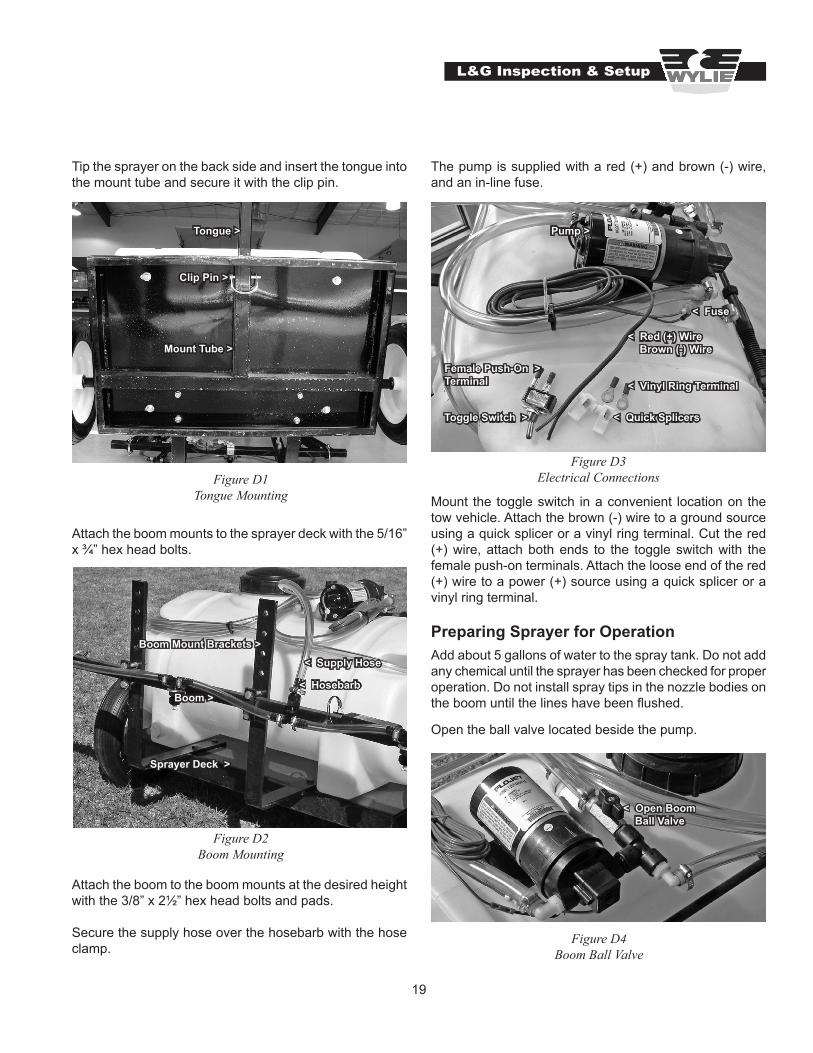
Tip the sprayer on the back side and insert the tongue into the mount tube and secure it with the clip pin.
Attach the boom mounts to the sprayer deck with the 5/16” x ¾” hex head bolts.
Attach the boom to the boom mounts at the desired height with the 3/8” x 2½” hex head bolts and pads.
Secure the supply hose over the hosebarb with the hose clamp.
Tongue >
Clip Pin >
Mount Tube >
Figure D1 Tongue Mounting
Boom Mount Brackets >
Boom >
< Supply Hose
< Hosebarb
Sprayer Deck >
Figure D2 Boom Mounting
L&G Inspection & Setup
The pump is supplied with a red (+) and brown (-) wire, and an in-line fuse.
Mount the toggle switch in a convenient location on the tow vehicle. Attach the brown (-) wire to a ground source using a quick splicer or a vinyl ring terminal. Cut the red (+) wire, attach both ends to the toggle switch with the female push-on terminals. Attach the loose end of the red (+) wire to a power (+) source using a quick splicer or a vinyl ring terminal.
Preparing Sprayer for OperationAdd about 5 gallons of water to the spray tank. Do not add any chemical until the sprayer has been checked for proper operation. Do not install spray tips in the nozzle bodies on the boom until the lines have been flushed.
Open the ball valve located beside the pump.
Figure D3Electrical Connections
Pump >
< Red (+) Wire Brown (-) Wire
Toggle Switch >
Female Push-On > Terminal < Vinyl Ring Terminal
< Quick Splicers
< Fuse
Figure D4 Boom Ball Valve
< Open Boom Ball Valve
20
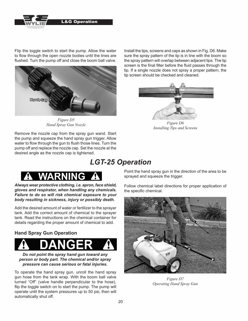
Flip the toggle switch to start the pump. Allow the water to flow through the open nozzle bodies until the lines are flushed. Turn the pump off and close the boom ball valve.
Remove the nozzle cap from the spray gun wand. Start the pump and squeeze the hand spray gun trigger. Allow water to flow through the gun to flush those lines. Turn the pump off and replace the nozzle cap. Set the nozzle at the desired angle as the nozzle cap is tightened.
Figure D5 Hand Spray Gun Nozzle
Nozzle Cap >
Do not point the spray hand gun toward any person or body part. The chemical and/or spray
pressure can cause serious or fatal injuries.
Always wear protective clothing, i.e. apron, face shield, gloves and respirator, when handling any chemicals. Failure to do so will risk chemical exposure to your body resulting in sickness, injury or possibly death.
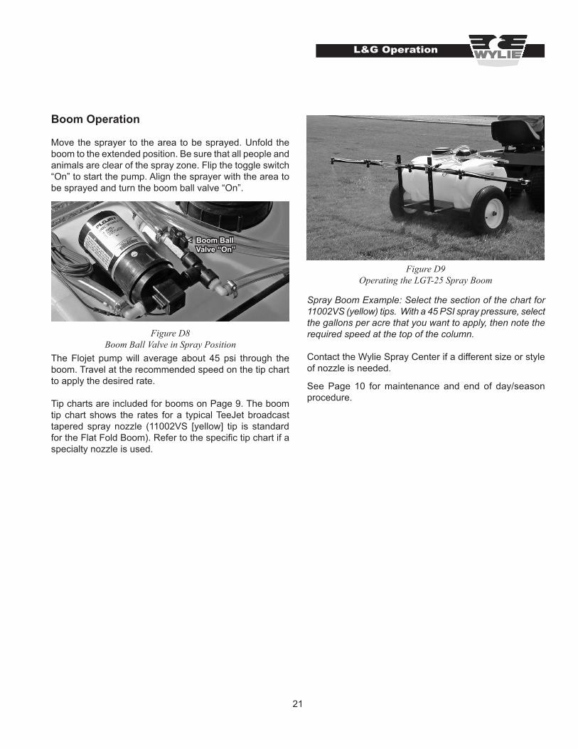
Install the tips, screens and caps as shown in Fig. D6. Make sure the spray pattern of the tip is in line with the boom so the spray pattern will overlap between adjacent tips. The tip screen is the final filter before the fluid passes through the tip. If a single nozzle does not spray a proper pattern, the tip screen should be checked and cleaned.
Figure D6Installing Tips and Screens
LGT-25 Operation
L&G Operation
Add the desired amount of water or fertilizer to the sprayer tank. Add the correct amount of chemical to the sprayer tank. Read the instructions on the chemical container for details regarding the proper amount of chemical to add.
Hand Spray Gun Operation
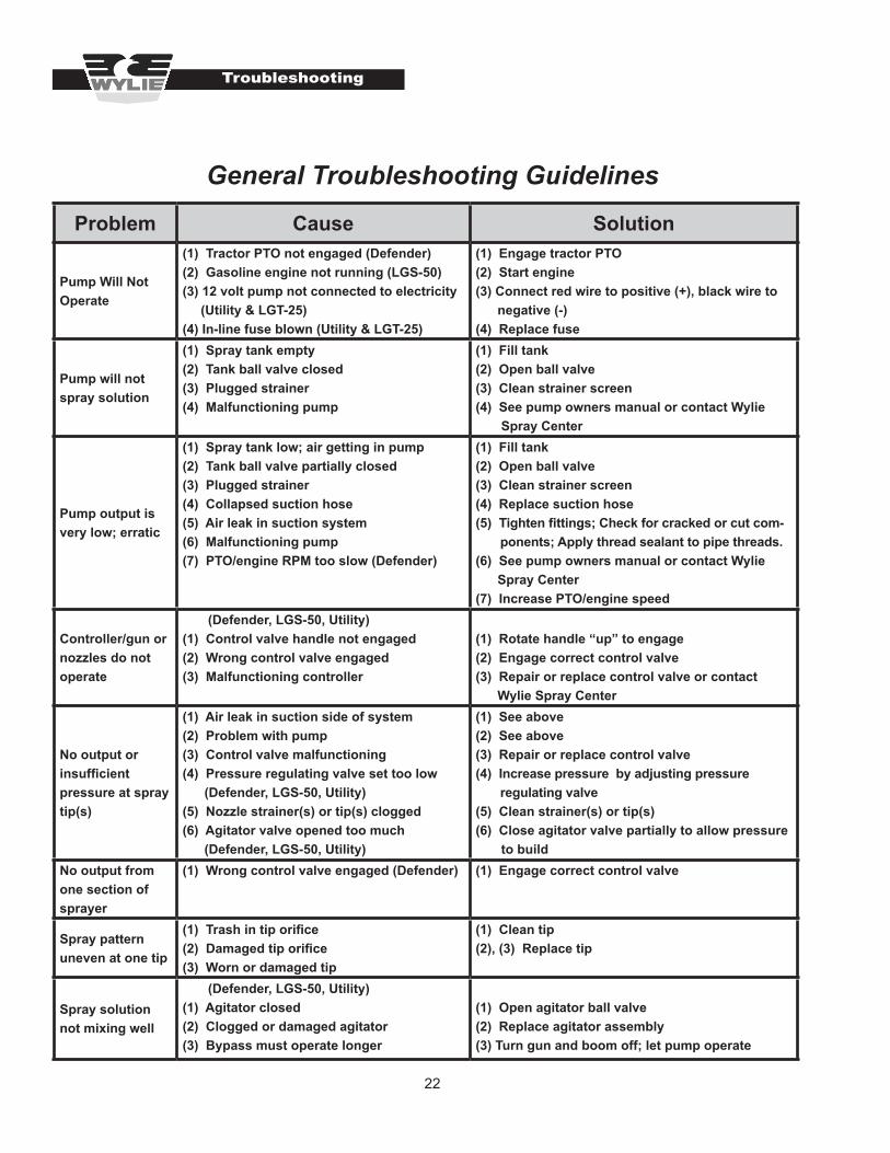
To operate the hand spray gun, unroll the hand spray gun hose from the tank wrap. With the boom ball valve turned “Off” (valve handle perpendicular to the hose), flip the toggle switch on to start the pump. The pump will operate until the system pressures up to 50 psi, then will automatically shut off.
Point the hand spray gun in the direction of the area to be sprayed and squeeze the trigger.
Follow chemical label directions for proper application of the specific chemical.
Figure D7Operating Hand Spray Gun
21
Spray Boom Example: Select the section of the chart for 11002VS (yellow) tips. With a 45 PSI spray pressure, select the gallons per acre that you want to apply, then note the required speed at the top of the column.
Contact the Wylie Spray Center if a different size or style of nozzle is needed. See Page 10 for maintenance and end of day/season procedure.
Boom Operation
Move the sprayer to the area to be sprayed. Unfold the boom to the extended position. Be sure that all people and animals are clear of the spray zone. Flip the toggle switch “On” to start the pump. Align the sprayer with the area to be sprayed and turn the boom ball valve “On”.
The Flojet pump will average about 45 psi through the boom. Travel at the recommended speed on the tip chart to apply the desired rate.
Tip charts are included for booms on Page 9. The boom tip chart shows the rates for a typical TeeJet broadcast tapered spray nozzle (11002VS [yellow] tip is standard for the Flat Fold Boom). Refer to the specific tip chart if a specialty nozzle is used.
L&G Operation
Figure D8 Boom Ball Valve in Spray Position
< Boom Ball Valve “On”
Figure D9 Operating the LGT-25 Spray Boom
22
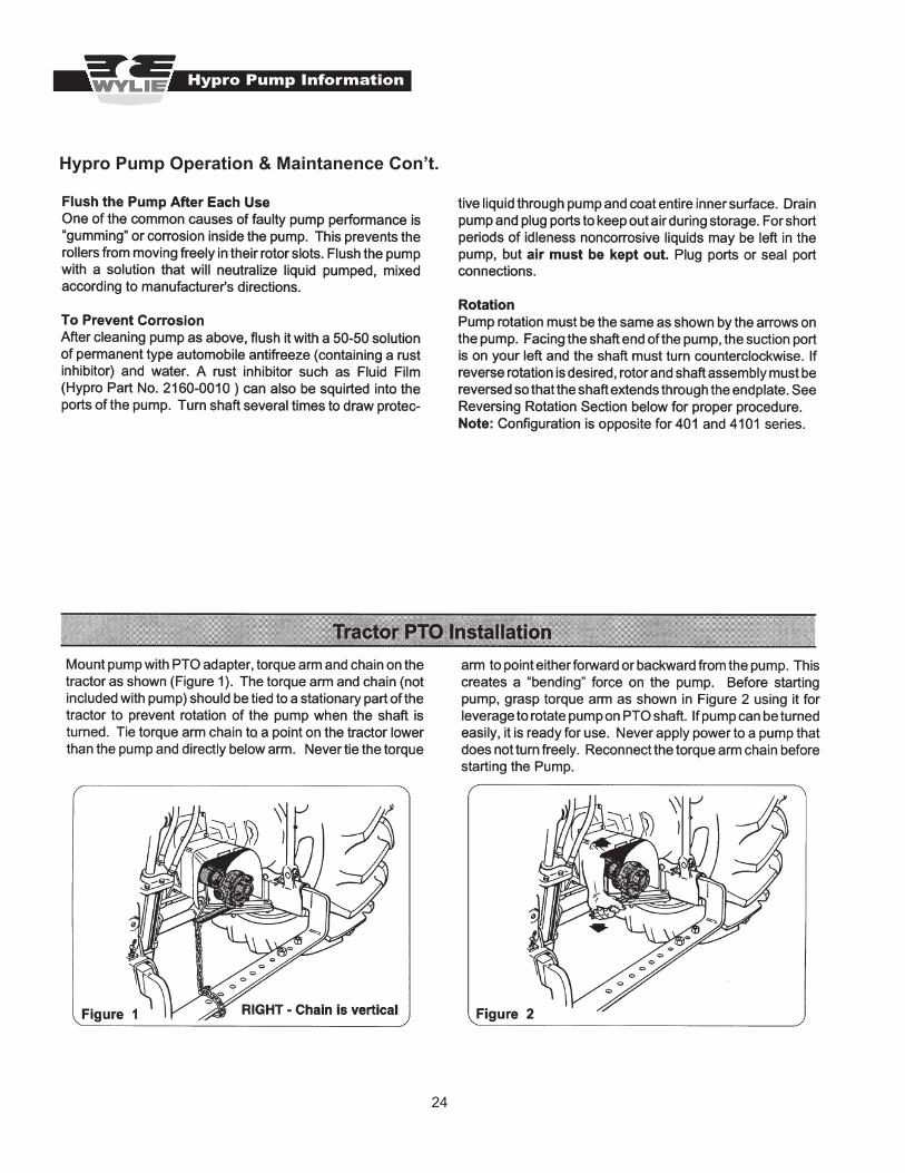
General Troubleshooting Guidelines
Troubleshooting
Problem Cause Solution
Pump Will Not Operate
(1) Tractor PTO not engaged (Defender)(2) Gasoline engine not running (LGS-50)(3) 12 volt pump not connected to electricity (Utility & LGT-25)(4) In-line fuse blown (Utility & LGT-25)
(1) Engage tractor PTO(2) Start engine(3) Connect red wire to positive (+), black wire to negative (-)(4) Replace fuse
Pump will not spray solution
(1) Spray tank empty(2) Tank ball valve closed(3) Plugged strainer(4) Malfunctioning pump
(1) Fill tank(2) Open ball valve(3) Clean strainer screen(4) See pump owners manual or contact Wylie Spray Center
Pump output is very low; erratic
(1) Spray tank low; air getting in pump(2) Tank ball valve partially closed(3) Plugged strainer(4) Collapsed suction hose(5) Air leak in suction system(6) Malfunctioning pump(7) PTO/engine RPM too slow (Defender)
(1) Fill tank(2) Open ball valve(3) Clean strainer screen(4) Replace suction hose(5) Tighten fittings; Check for cracked or cut com- ponents; Apply thread sealant to pipe threads.(6) See pump owners manual or contact Wylie Spray Center(7) Increase PTO/engine speed
Controller/gun or nozzles do not operate
(Defender, LGS-50, Utility)(1) Control valve handle not engaged(2) Wrong control valve engaged(3) Malfunctioning controller
(1) Rotate handle “up” to engage(2) Engage correct control valve(3) Repair or replace control valve or contact Wylie Spray Center
No output or insufficient pressure at spray tip(s)
(1) Air leak in suction side of system(2) Problem with pump(3) Control valve malfunctioning(4) Pressure regulating valve set too low (Defender, LGS-50, Utility)(5) Nozzle strainer(s) or tip(s) clogged(6) Agitator valve opened too much (Defender, LGS-50, Utility)
(1) See above(2) See above(3) Repair or replace control valve(4) Increase pressure by adjusting pressure regulating valve(5) Clean strainer(s) or tip(s)(6) Close agitator valve partially to allow pressure to build
No output from one section of sprayer
(1) Wrong control valve engaged (Defender) (1) Engage correct control valve
Spray pattern uneven at one tip
(1) Trash in tip orifice(2) Damaged tip orifice(3) Worn or damaged tip
(1) Clean tip(2), (3) Replace tip
Spray solution not mixing well
(Defender, LGS-50, Utility)(1) Agitator closed(2) Clogged or damaged agitator(3) Bypass must operate longer
(1) Open agitator ball valve(2) Replace agitator assembly(3) Turn gun and boom off; let pump operate

23
Hypro Pump Information
Hypro Pump Information
24
Hypro Pump Information
Hypro Pump Operation & Maintanence Con’t.

25
Hypro Pump Information
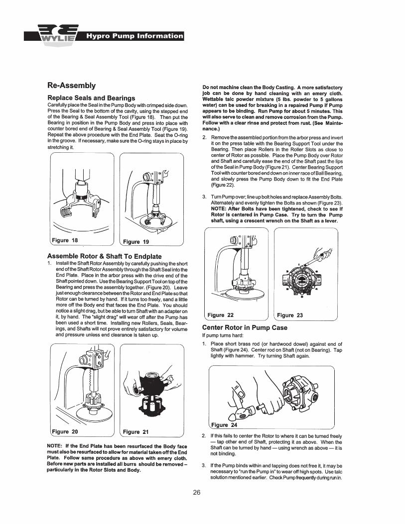
26
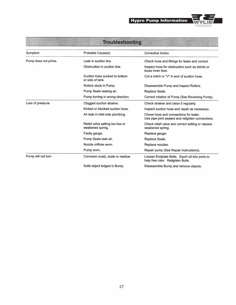
Hypro Pump Information
27
Hypro Pump Information

28
Hypro Pump Information

29
Flojet Pump Information

30
Flojet Pump Information