Operators Manual - Snap-on Equipment
66
Operators Manual Portable Imaging Alignment Systems with Pro42
Transcript of Operators Manual - Snap-on Equipment

Operators ManualPortable Imaging Alignment Systems with Pro42

Blank page

Page III
SAFETY INFORMATION
For your safety, read this manual thoroughly before operating the equipment.
The Aligner is intended for use by properly trained skilled automotive technicians. The safety messages presented in this section and throughout the manual are reminders to the operator to exercise extreme care when performing wheel alignments with this product.
There are many variations in procedures, techniques, tools, and parts for servicing vehicles, as well as the skill of the individual doing the work. Because of the vast number of vehicle applications and potential uses of the product, the manufacturer cannot possibly anticipate or provide advice or safety messages to cover every situation. It is the automotive technician’s responsibility to be knowledgeable of the vehicle to be aligned. It is essential to use proper service methods and perform wheel alignments in an appropriate and acceptable manner that does not endanger your safety, the safety of others in the work area or the equipment or vehicle being serviced.
It is assumed that, prior to using the Aligner, the operator has a thorough understanding of the vehicle systems being serviced. In addition, it is assumed he has a thorough knowledge of the operation and safety features of the alignment rack or lift, and has the proper hand and power tools necessary to per-form wheel alignments.
When using your garage equipment, basic safety precautions should always be followed, including:
Read and understand all instructions.1. Care must be taken as burns can occur from touching hot parts.2. The socket-outlet (wall outlet) shall be located near the equipment and shall be easily accessible.3. Do not operate power tools or equipment with a damaged power cord or if the equipment has been dropped 4. or damaged until it has been examined by a qualified serviceman.Do not let electric cord hang over edge of table, bench or counter or come in contact with hot manifolds or 5. moving fan blades.If an extension cord is necessary, a cord with a current rating equal to or more than that of the equipment 6. should be used. Cords rated for less than the equipment may overheat. Care should be taken to arrange the cord so that it will not be tripped over or pulled.Always unplug equipment from electrical outlet when not in use. Never use the cord to pull the plug from the 7. outlet. Grasp plug and pull to disconnect.Let equipment cool completely before putting away. Loop cord loosely around equipment when storing.8. To reduce the risk of fire, do not operate equipment in the vicinity of open containers of flammable liquids, such 9. as gasoline.Adequate ventilation should be provided when working on operating internal combustion engines.10. Keep hair, loose clothing, fingers, and all parts of body away from moving parts.11. To reduce the risk of electrical shock, do not use on wet surfaces or expose to rain.12. Use only as described in this manual. Use only manufacturer’s recommended attachments.13. ALWAYS WEAR SAFETY GLASSES. Everyday eyeglasses only have impact resistant lenses, they are NOT 14. safety glasses.Know and understand the proper operating procedures for all power tools used.15. Caution:16. Risk of explosion if any battery is replaced by an incorrect type. Dispose of used batteries according to local and state government regulations.
IMPORTANT!! SAVE THESE INSTRUCTIONSDO NOT DISCARD!!

Chapter 1 - Safety
Page IV
Risk of electrical shock. Do not operate equipment with a damaged power cord or if the equipment has •beendroppedordamaged,untilithasbeenexaminedbyaqualifiedserviceperson.If an extension cord is necessary, a cord with a current rating equal to or greater •than that of the equipment should be used. Cords rated for less current than the equipmentcanoverheat.Unplugequipmentfromelectricaloutletwhennotinuse.Neverusethecordto•pull the plug from the outlet. Grasp plug and pull to disconnect.Do not expose the equipment to rain. Do not use on wet surfaces.•Plug unit into correct power supply.•Donotremoveorbypassgroundingpin.•
Contact with high voltages can cause death or serious injury.
Risk of electrical shock. High voltages are present within the console unit.Therearenouserserviceableitemswithintheconsoleotherthanthekeyboard•and printer. Serviceontheunitmustbeperformedbyqualifiedpersonnel.•Do not open any part of the console other than noted areas.•Turnpowerswitchoffandunplugtheunitbeforeservicing.•
Contact with high voltages can cause death or serious injury.
Risk of eye injury. Debris, dirt, and fluids may drop from vehicles.Knockoffanyloosedebris.Cleansurfacesasneededtoavoidanymaterials•from falling.Wearapprovedsafetyglasseswhenservicing.•
Debris, dirt, and fluids can cause serious eye injury.
Risk of crushing. Vehicles may roll off alignment lift if not secured.Leaveautomatictransmissioninparkormanualtransmissioningearunless•equipmentoperationstepsrequirevehicleinneutral.Applyparkingbrakeunlessequipmentoperationstepsrequirewheelmove-•ment.Usewheelchockswhenevervehicleispositionedonthelift.•Followrackorliftmanufacturer’ssafetyrecommendationswhenliftingave-•hicle.
Vehicles rolling off lifts can cause death or serious injury.
Safety INSTRUCTIONSIMPORTANT!! SAVE THESE INSTRUCTIONS

Page V
Risk of entanglement or crushing. There are moving parts on vehicle lifts during operation.• Keep all persons clear of lifts.• Readliftmanufacturer’soperationinstructionscarefully.• Followliftmanufacturer’ssafetyrecommendations.Contact with moving parts could cause injury.
Risk of pinching or crushing body parts when jacking vehicles.• Keephandsandotherbodypartsawayfromjackingsurfaces.• Donotuseunapprovedadapters(i.e.woodenblocks)whenjackingavehicle.• Donotbypassanyjackmanufacturer’ssafetyfeatures.• Readjackmanufacturer’soperationinstructionscarefully.• Followjackmanufacturer’ssafetyrecommendations.Improperly used or maintained jacks can cause injury.
Risk of burns.• Do not touch hot exhaust systems, manifolds, engines, radiators, etc.• Weargloveswheneverperformingaservicenearhotcomponents.Hot components can cause burns.
Risk of injury. Tools may break or slip if improperly used or maintained.• Usethecorrecttoolforthetask.• Frequentlyinspect,clean,andlubricate(ifrecommended)alltools.• Followrecommendedprocedureswhenperformingvehicleservices.Tools that break or slip can cause injury.

Page 6
Table of Contents
Table of Contents
SAFETY INFORMATION .......................................................................................................... III
Introduction ............................................................................................................................... 9Assembly and Setup................................................................................................................... 9Power On Sequence .................................................................................................................. 9Software ..................................................................................................................................... 9Shutting Down the Computer ................................................................................................... 10Screen Layout and Navigation ................................................................................................. 11Toolbar Buttons......................................................................................................................... 12Main Carousel Bar .................................................................................................................... 14
Preferences - Setup ................................................................................................................ 15Preferences Selections:............................................................................................................ 15
Performing a 4-Wheel Alignment .......................................................................................... 17Basic Alignment Procedures..................................................................................................... 18Positioning the Vehicle on the Lift............................................................................................. 18Attach the Targets/Pods ........................................................................................................... 19Begin Wizard Procedure........................................................................................................... 20Begin a New Alignment ............................................................................................................ 21Enter Customer Data ................................................................................................................ 21Adding Customer Information ................................................................................................... 21Selecting a Stored Record........................................................................................................ 21Adding a New Customer........................................................................................................... 22Editing an Existing Record ....................................................................................................... 22Backup and Restore ................................................................................................................. 22Vehicle Manufacturer ................................................................................................................ 22Selecting a Default Make.......................................................................................................... 23Vehicle Year ............................................................................................................................. 23Vehicle Model ........................................................................................................................... 23Using an Optional VIN Reader ................................................................................................. 23Editing Specifications ............................................................................................................... 24Vehicle Stability Programming .................................................................................................. 24Adjustment Animations ............................................................................................................. 25Additional Assistance................................................................................................................ 25Powering the Pods ................................................................................................................... 26Runout Compensation .............................................................................................................. 27Rear Runout ............................................................................................................................. 28Front Runout............................................................................................................................. 29Perform Steering Angle Measurement ..................................................................................... 30

Page 7
Table of Contents
Wheel Roll Message................................................................................................................. 31Readings Screen ...................................................................................................................... 32Turn Wheels Straight Ahead ..................................................................................................... 32Adjust Front First ...................................................................................................................... 33Cross Values / Total Toe ......................................................................................................... 33Readings Toolbar Buttons ....................................................................................................... 34Level and Lock Steering Wheel ................................................................................................ 35All Readings Screen ................................................................................................................. 35Print Results ............................................................................................................................. 36
Measure Menu......................................................................................................................... 37Measuring Caster/SAI and TOOT............................................................................................. 38Steering Level Check ............................................................................................................... 39Single Wheel Rollback.............................................................................................................. 39Rolling Runout - (Advanced Option) ......................................................................................... 41Vehicle Dimensions - (Advanced Option) ................................................................................ 43Measuring SAI Only Elevated................................................................................................... 43Maximum Turns ........................................................................................................................ 44Toe Curve Change .................................................................................................................. 45Camber at Zero Toe .................................................................................................................. 45
Adjust Menu ............................................................................................................................ 46Adjust Caster and/or Camber, and Toe Elevated ..................................................................... 47EZ Toe ...................................................................................................................................... 48Shims and Kits ........................................................................................................................ 49Adjust A-Arms ........................................................................................................................... 50Wheel Off Caster, Camber, Toe Adjust .................................................................................... 51Offset Cams and Bushings ....................................................................................................... 52Cradle Adjust (Optional Advanced Feature) ............................................................................. 52Drag Link Adjust (Optional Advanced Feature) ........................................................................ 54Single Tie Rod Adjust (Optional Advanced Feature) ................................................................ 55Calibration Menu ...................................................................................................................... 56ISO Certification ....................................................................................................................... 57
Calibration ............................................................................................................................... 59Rear Calibration........................................................................................................................ 59Front Calibration ....................................................................................................................3-61Calibration factors..................................................................................................................3-62Calibration history ..................................................................................................................3-62Calibration Backup and Restore ............................................................................................3-62Sensor Diagnostics................................................................................................................3-63

Page 8
Table of Contents

Page 1-9
Chapter I Introduction
IntroductionThe document covers basic and advanced software features which may or may not be included in all aligner models. This document primarily is designed to cover software naviga-tion and features with minimum regard to the hardware platform in which it resides. There are several variations of aligner models each of which may utilize different features of the base software package. References are often made to other sections of the Manual.
Assembly and SetupInstallation and setup of a new aligner must be handled by a qualified Technical Repre-sentative.
All software is loaded onto the computer’s hard drive. The software shipped with the unit serve as a backup and is not needed when performing alignments.
Instructions for operational setup of the aligner program are covered in detail in Section 2 of this Operator’s Manual. The setups for the PC hardware and Microsoft Windows® are preset at the factory and should not be altered.
Power On SequenceThe main power switch is located on the back side of the Computer Console. Turn the com-puter console switch ON. Some models will automatically boot to the alignment program others may require pressing the on switch of the PC to begin the power-on sequence.
When the power switch is turned on, the unit initiates the computer boot-up. Text should appear on the screen as boot-up begins and counting numbers are shown as the memory of the unit is checked and verified. Many ad-ditional lines of computer configuration will ap-pear on screen and scroll up as the computer completes the system boot sequence. The Home screen will appear next as the software finishes loading.
The boot sequence will take a few moments. If any problems are encountered during the Power On boot-up sequence, consult the service representative in your area.
SoftwareThere are several ways to control movement within the aligner program. First, each unit is shipped with a pointing device – a mouse. The unit can be equipped with an optional hand-held remote control whose various buttons permit full aligner function. Study the Figures on the following pages carefully to become familiar with the functions of each button.
Windows® is a point-and-click software envi-ronment. The Aligner software follows Win-dows® navigation conventions. Use the point-ing device to navigate through the software as you would with any Windows® program. Most functions require a single mouse click to initiate, while a few require double-clicks. The right mouse button is not utilized within the alignment software.
A standard keyboard is included for data entry. All aligner functions can also be controlled from the keyboard as well as the remote. The function keys (F1 - F12) located on the top row of the keyboard have decals that are the equivalent of the remote and keypad buttons. Refer to the diagram for identification of the icons and their respective functions.
The keyboard has a “Print Screen” key. When this key is pressed the currently displayed screen will be captured and printed.

Page 1-10
Chapter I Introduction
!! IMPORTANT NOTE !! Shutting Down the Computer
To avoid damaging important files It is necessary to shut down Windows® properly before turning off or restarting the aligner or the computer.
Use the following steps to shut down the aligner from within the Alignment software:1. Return to the Home Alignment screen.
2. Power off the PC using Software control, the “SHUT DOWN WINDOWS®” icon at the lower right corner of the Home Screen followed by turning the switch off at the rear of the aligner.
Note: The switch must remain off a minimum of 10 seconds before it can be turned back on.
From the Windows® desktop: 1. Close any programs or applications that
may have been opened.
2. Click the Start button, and then click Shut Down.
3. On the Shut Down Windows® box that ap-pears, select “Shut down the computer?” Click “Yes” to proceed.
4. The computer will automatically shut-down. After the computer finishes shutting down, turn the switch off at the rear of the aligner.
Note: The switch must remain off a minimum of 10 seconds before it can be turned back on.

Page 1-11
Chapter I Introduction
4
1 2 3
5
Screen Layout and NavigationThe software features a common interface throughout its many screens. Becoming familiar with the various screen navigation functions is essential for efficient use of the aligner.
1 - Carousel Control - Select primary alignment functions from the scrolling icons. Icons can be “Scrolled” up or down the selection window using either the mouse wheel or the Windows® scroll bar. They can be selected by clicking on the desired icon with the mouse pointer.
2 - Previous and Next Buttons
3 - Toolbar – these buttons appear on every screen, and correspond to the F1-F12 keys on the keyboard, as well as the keys on the remote. The functions for F1-F4 are common to every screen, while the functions of F5-F12 vary depending on the screen.
4 - Display Area - When a desired function (such as Display Meters) is selected, the action is displayed in this screen area.
5 - Shut Down Windows® - When it is necessary to close the alignment program and Windows® - use this icon to properly close all application to avoid damaging any files in use.
Page 1-12
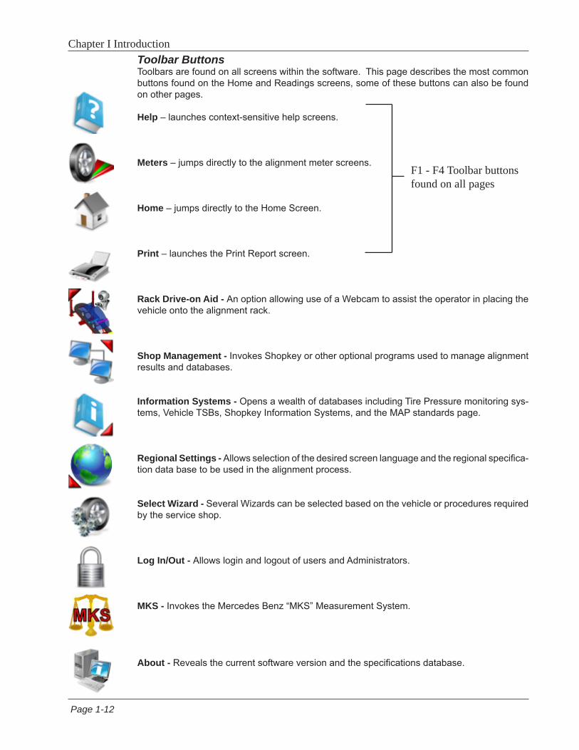
Chapter I IntroductionToolbar ButtonsToolbars are found on all screens within the software. This page describes the most common buttons found on the Home and Readings screens, some of these buttons can also be found on other pages.
Help – launches context-sensitive help screens.
Meters – jumps directly to the alignment meter screens.
Home – jumps directly to the Home Screen.
Print – launches the Print Report screen.
Rack Drive-on Aid - An option allowing use of a Webcam to assist the operator in placing the vehicle onto the alignment rack.
Shop Management - Invokes Shopkey or other optional programs used to manage alignment results and databases.
Information Systems - Opens a wealth of databases including Tire Pressure monitoring sys-tems, Vehicle TSBs, Shopkey Information Systems, and the MAP standards page.
Regional Settings - Allows selection of the desired screen language and the regional specifica-tion data base to be used in the alignment process.
Select Wizard - Several Wizards can be selected based on the vehicle or procedures required by the service shop.
Log In/Out - Allows login and logout of users and Administrators.
MKS - Invokes the Mercedes Benz “MKS” Measurement System.
About - Reveals the current software version and the specifications database.
F1 - F4 Toolbar buttons found on all pages

Page 1-13
Chapter I Introduction
Measure – from any Readings screen, launches the Measure screen.
Adjust – from any Readings screen, launches the Adjust features.
Zoom – makes the selected meter fill the entire screen.
Unzoom – returns from a zoomed meter to the standard meter screen.
Edit - Edit the Customer data currently in use.
Aligner Diagnostics - When in any of the Readings screens select this function to view the camera image or view the camera data. This feature is useful in the event the cameras cannot “See” a target for some reason.
Camera View - Select to view the live camera image.
Rolling Runout (Advanced Option) - Select this feature to allow runout compensation without raising the vehicle. This feature is useful for vehicles which display a tendency to not return to ride height after being raised for conventional runout.
Single Wheel Rollback - Select this feature to compensate only one wheel. If the target has been removed to replace parts or service the wheel assembly, select to re-compensate only that one wheel. The wheel assembly is raised to perform compensation.

Page 1-14
Chapter I Introduction
Main Carousel BarThese buttons or icons are located on the sliding “Carousel” located to the left of the display screen. The Carousel bar contents will change with the content of the screen currently dis-played. Subjects related to alignment will be displayed when performing an actual alignment while subjects pertaining to aligner Setup or Calibration may be displayed when Calibration or Preferences is selected. All Carousel Bar selections when “Moused Over” will display a “tool tip” which briefly explains its function.
Diagnostics - Certain alignment system diagnostics are accessed through this selection. These diagnostics are generally used by qualified service personnel to assist with problem solving.
Data Base Utilities - Select to back-up, restore or trim the customer database.
Customer Data - Use to select or add information to the customer database.
Vehicle Selection - Select the vehicle make, year, model and sub-model to be measured.
Begin Alignment - Select to start the alignment wizard and all its content path. Selections include choosing or adding a customer name, choosing a vehicle, and performing all the neces-sary functions for reliable alignment readings.
Quick Alignment - Select to get alignment readings quickly without the tasks of selection cus-tomer name or performing inspections etc. This feature is helpful when checking a vehicles conformance to specification before the customer commits to the actual alignment.
Alignment modification Wizard - This is useful for making vehicle modifications. This icon invokes the Vehicle Modification Wizard (Advanced Option only). It is used to recall a previ-ous Vehicle Modification session or to start a new one. Recalling a previous session recalls readings for comparison.
Vehicle Specifications - Select to view the specifications of the vehicle currently selected. Specs can be edited and renamed as a “Custom Vehicle” from this screen as well.
Preferences - User desired characteristics can be tailored to the operators “Preferences” in this selection. Security of the system, the system configuration, store name and address, units of measure, languages, and others are selected for the user.
Calibration - Various subsystems are calibrated with this selection. Calibration factors can also be backed-up and restored from here.
Page 2-15
Chapter II Setup - Preferences
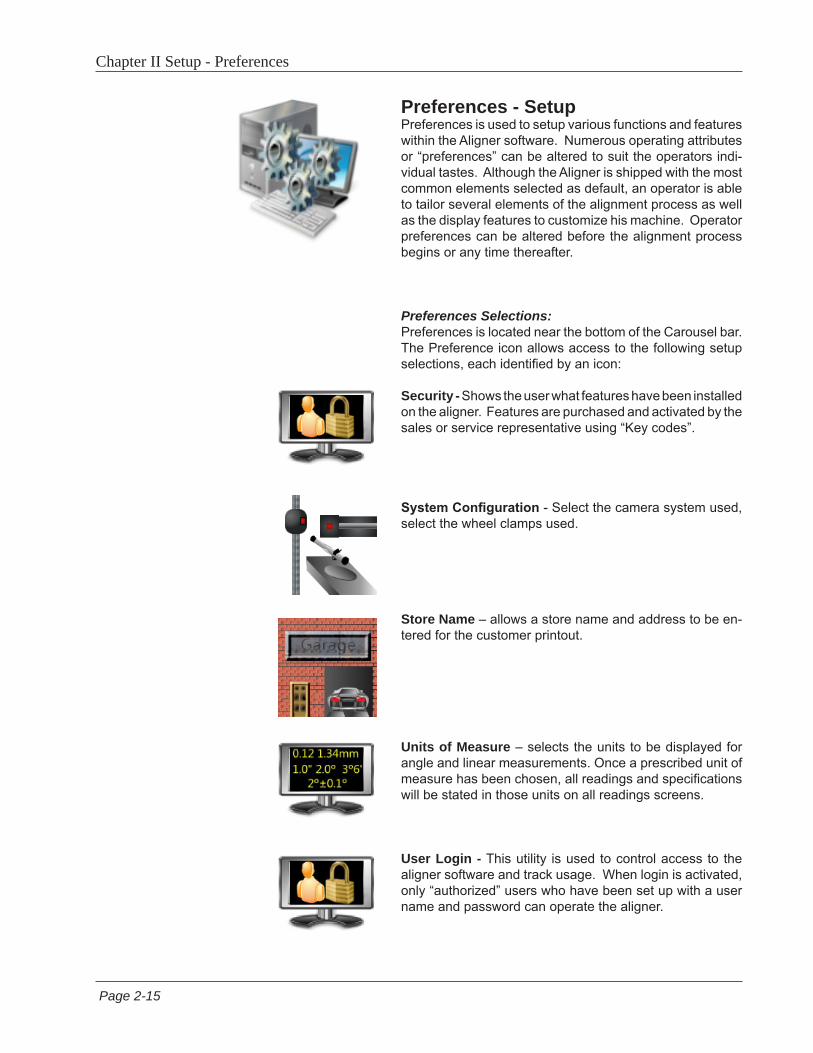
Preferences - SetupPreferences is used to setup various functions and features within the Aligner software. Numerous operating attributes or “preferences” can be altered to suit the operators indi-vidual tastes. Although the Aligner is shipped with the most common elements selected as default, an operator is able to tailor several elements of the alignment process as well as the display features to customize his machine. Operator preferences can be altered before the alignment process begins or any time thereafter.
Preferences Selections:Preferences is located near the bottom of the Carousel bar. The Preference icon allows access to the following setup selections, each identified by an icon:
Security - Shows the user what features have been installed on the aligner. Features are purchased and activated by the sales or service representative using “Key codes”.
System Configuration - Select the camera system used, select the wheel clamps used.
Store Name – allows a store name and address to be en-tered for the customer printout.
Units of Measure – selects the units to be displayed for angle and linear measurements. Once a prescribed unit of measure has been chosen, all readings and specifications will be stated in those units on all readings screens.
User Login - This utility is used to control access to the aligner software and track usage. When login is activated, only “authorized” users who have been set up with a user name and password can operate the aligner.
Page 2-16
Chapter II Setup - Preferences
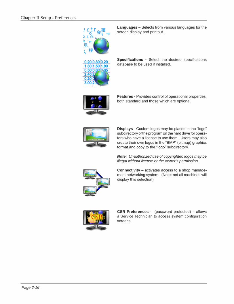
Languages – Selects from various languages for the screen display and printout.
Specifications - Select the desired specifications database to be used if installed.
Features - Provides control of operational properties, both standard and those which are optional.
Displays - Custom logos may be placed in the “logo” subdirectory of the program on the hard drive for opera-tors who have a license to use them. Users may also create their own logos in the “BMP” (bitmap) graphics format and copy to the “logo” subdirectory.
Note: Unauthorized use of copyrighted logos may be illegal without license or the owner’s permission.
Connectivity – activates access to a shop manage-ment networking system. (Note: not all machines will display this selection)
CSR Preferences - (password protected) – allows a Service Technician to access system configuration screens.

Page 3-17
Chapter III Operation
Steps to Performing a 4-Wheel AlignmentThere are many reasons why a wheel alignment may be performed on a vehicle such as:
Accelerated or uneven tire wearPull, wandering, or other steering / handling problems
After replacement of worn suspension or steering system componentsAfter-collision repairs
Routine vehicle maintenance
Regardless of the reasons for alignment, it is important that the technician performs these Basic steps neces-sary to address and correct all problems. Other diagnostics are available for advanced testing.
1. Gather information from the vehicle owner – ask about any symptoms of misalignment. Inquire if the vehicle has been in a collision or has had any parts replaced recently.
2. Perform a test drive to verify owner’s complaint – try to recreate the problem. If unable to duplicate, have the vehicle owner explain further or have him/her drive with you.
3. Place vehicle on the alignment lift – center the vehicle on the lift and turntables. Raise the lift to a solid, level lock position.
4. Inspect the tires for any signs of abnormal wear – tires often reflect many misalignment conditions.
5. Perform a thorough component inspection. Replace defective parts prior to performing the alignment. Always check tire pressure and ride height.
6. Mount measuring targets/pods to the vehicles wheels. Use the safety straps in the event of grip failure.
7. Choose the proper Wizard procedure for the vehicle.
8. Perform compensation or rollback – the purpose of performing compensation is to eliminate measurement errors due to the wheel runout and clamp mounting error.
9. Measure caster, camber, and toe.
10. Determine what needs to be done – Examine the vehicle and any reference materials to determine the pro-cedures for angle corrections. Determine what items are needed to correct any problems (i.e. aftermarket kits, special tools, etc.).
11. Make any needed angle corrections – center the steering wheel carefully when prompted. Use this order of adjustment:
a. Rear camber b. Rear toe c. Front caster d. Front camber e. Front toe
12. Re-center the steering wheel and readjust front toe if needed – crooked steering wheels are the leading cause of customer dissatisfaction with wheel alignments.
13. Print the results – the printout is useful for showing the customer before and after results. Many shops keep a printout on file for future reference.
14. Perform a test drive to verify proper alignment.
Page 3-18
Chapter III Operation
Basic Alignment Procedures
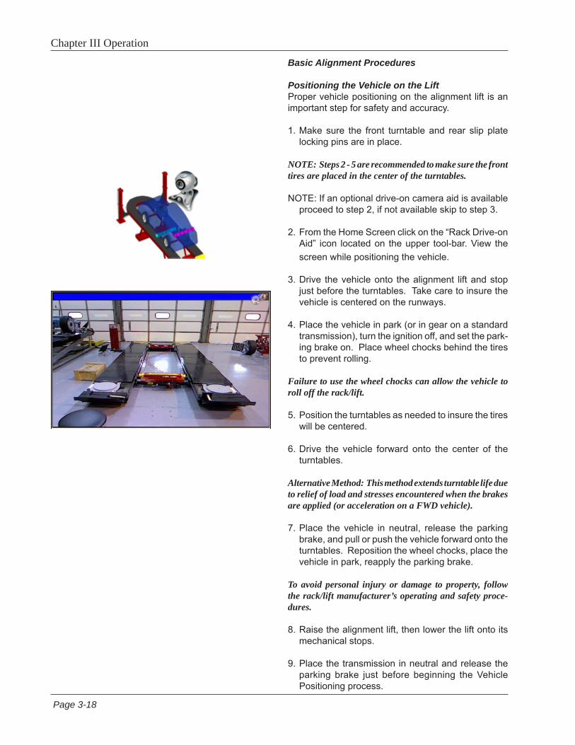
Positioning the Vehicle on the LiftProper vehicle positioning on the alignment lift is an important step for safety and accuracy.
1. Make sure the front turntable and rear slip plate locking pins are in place.
NOTE: Steps 2 - 5 are recommended to make sure the front tires are placed in the center of the turntables.
NOTE: If an optional drive-on camera aid is available proceed to step 2, if not available skip to step 3.
2. From the Home Screen click on the “Rack Drive-on Aid” icon located on the upper tool-bar. View the screen while positioning the vehicle.
3. Drive the vehicle onto the alignment lift and stop just before the turntables. Take care to insure the vehicle is centered on the runways.
4. Place the vehicle in park (or in gear on a standard transmission), turn the ignition off, and set the park-ing brake on. Place wheel chocks behind the tires to prevent rolling.
Failure to use the wheel chocks can allow the vehicle to roll off the rack/lift.
5. Position the turntables as needed to insure the tires will be centered.
6. Drive the vehicle forward onto the center of the turntables.
Alternative Method: This method extends turntable life due to relief of load and stresses encountered when the brakes are applied (or acceleration on a FWD vehicle).
7. Place the vehicle in neutral, release the parking brake, and pull or push the vehicle forward onto the turntables. Reposition the wheel chocks, place the vehicle in park, reapply the parking brake.
To avoid personal injury or damage to property, follow the rack/lift manufacturer’s operating and safety proce-dures.
8. Raise the alignment lift, then lower the lift onto its mechanical stops.
9. Place the transmission in neutral and release the parking brake just before beginning the Vehicle Positioning process.

Page 3-19
Chapter III Operation
Attach the Targets/PodsThe targets/pods are attached to the wheels using the wheel clamps. The targets go on the front wheels, the measuring pods on the rear.
There are several methods of attachment depending on the wheel lip configuration. The integrated claws provide the versatility needed to grab virtually any wheel. The claws can be rotated to adjust for different wheel configurations.
Claws may have sharp edges. To avoid personal injury, use caution when working with wheel clamps.
The clamps should be installed in a straight-up vertical manner (knob at the top).
Use the mounting method that provides the greatest security to keep the target from falling off the wheel. Most wheels can be grabbed from the outside-in by placing the claws between the bead of the tire and the outside edge of the rim. Others can be mounted on the inside of the rim such as with steel wheels.
For outside rim mounting:1. Extend the clamp to a size slightly larger than the
rim by turning the knob.
2. Place the upper claws on the outside of the top of the rim. Push the claws in between the tire bead and the rim. It may be necessary to “pop” the upper clamp bracket with the palm of your hand to seat well. Note that it is not necessary for the clamp to be mounted perfectly vertical on the wheel.
3. Tighten the clamp by turning the knob clockwise until the lower claws engage the rim.
4. Push the lower claws into place. Again, it may be necessary to pop them in further for security. Continue tightening the knob until secure.
5. Test the security by pulling outwards on the clamp. If it comes off easily, reattach the clamp or select an alternative mounting method.

Page 3-20
Chapter III Operation
Begin Wizard ProcedureThe Wizard procedure sets the aligner to follow a cer-tain process path resulting in a completed alignment. Each pre-programmed procedure, called a Wizard, sets the aligner up to perform certain functions in a predetermined order and determines whether certain functions can be skipped.
Wizard versus Manual OperationWhen the Run Wizard icon is selected from the Home Screen, the alignment process is performed using the Wizard that is currently selected.
Special Wizard Procedures (Optional)Several special procedures are pre-programmed to follow manufacturer’s recommended alignment methods.
When the Aligner is turned on for the first time a “factory default” Wizard is in place. Special as well as OEM Wizards can be set to default.
The following procedures are a sample of a Standard Alignment Wizard from start to finish.
Run WizardClick on the Run Wizard icon on the Home Screen Carousel Bar.
Quick AlignSelecting this icon starts the alignment procedures while skipping screens such as “Entering Customer Data”.
Page 3-21
Chapter III Operation
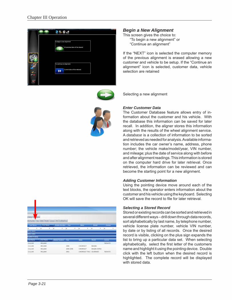
Begin a New AlignmentThis screen gives the choice to: “To begin a new alignment” or “Continue an alignment”
If the “NEXT” icon is selected the computer memory of the previous alignment is erased allowing a new customer and vehicle to be setup. If the “Continue an alignment” icon is selected, customer data, vehicle selection are retained
Selecting a new alignment
Enter Customer DataThe Customer Database feature allows entry of in-formation about the customer and his vehicle. With the database this information can be saved for later recall. In addition, the aligner stores this information along with the results of the wheel alignment service.A database is a collection of information to be sorted and retrieved as needed for analysis. Available informa-tion includes the car owner’s name, address, phone number; the vehicle make/model/year, VIN number, and mileage; plus the date of service along with before and after alignment readings. This information is stored on the computer hard drive for later retrieval. Once retrieved, the information can be reviewed and can become the starting point for a new alignment.
Adding Customer InformationUsing the pointing device move around each of the text blocks, the operator enters information about the customer and his vehicle using the keyboard. Selecting OK will save the record to file for later retrieval.
Selecting a Stored RecordStored or existing records can be sorted and retrieved in several different ways – drill down through data records, sort alphabetically by last name, by telephone number, vehicle license plate number, vehicle VIN number, by date or by listing of all records. Once the desired record is visible, clicking on the plus sign expands the list to bring up a particular data set. When selecting alphabetically, select the first letter of the customers name and highlight it using the pointing device. Double click with the left button when the desired record is highlighted. The complete record will be displayed with stored data.

Page 3-22
Chapter III Operation
Adding a New CustomerA new record can be entered by clearing all informa-tion on the data window. Information is cleared by selecting Clear Fields on the toolbar (F7). Once the screen has been cleared, enter the new customer information as desired. If another record is desired for an existing customer, highlight his name by using the pointing device, and begin entering information at the blank screen.
Editing an Existing RecordAn existing record can be edited by selecting the desired customer record. Once the record is displayed, move between information fields with the pointing device or TAB key. When the “I” bar is within the field to be edited, make the desired corrections. Data is saved when “OK” is entered.
Backup and RestoreDatafiles can be backed-up for security and restored upon demand. See the “Maintenance” chapter for more information on this feature.
Select Vehicle Manufacturer, Year and Model
Note: The order the manufacturer, year, and model appear will vary depending on how the specifications are set up (see Setup).
Vehicle ManufacturerThis screen shows the vehicle manufacturers in speci-fication database. The vertical scroll bar on the right indicates there are additional choices further down the page. Click on the down arrow on the scroll bar or scroll up/down the selections with the mouse wheel. Once the desired manufacturer is in view, double-click on the name to expand out the year or model selections. Double-click again to contract.

Page 3-23
Chapter III Operation
Selecting a Default MakeTo select a desired Make of Vehicle as “Default so it comes up first every time, highlight the Make then click on “F10” select default make Icon. This will anchor the selection. This is useful for dealership or shops that work on same makes the majority of the time.
TIP: To move to the manufacturer selection quicker, using the keyboard, press the first letter of the manu-facturer name. This causes the selection bar to move directly to the first name starting with that letter (i.e. press “H” - moves to Honda).
Vehicle Year Select the year of manufacture using the up/down keys or pointing device on the scroll bar to move up or down to the desired year, then double-click or press the right arrow key to expand out the years this model was made.
Vehicle ModelUse the direction keys or pointing device to select the model of the vehicle, then select “OK”, press Enter, or double click the selection.
Using an Optional VIN ReaderIf the aligner is equipped with an optional VIN Reader kit, the vehicle can be entered quickly and with as-surance the correct sub-model is selected. With the scanner properly installed, simply read the VIN bar code of the vehicle being aligned while the “I” bar is located in the “VIN Entry” box located on the vehicle selection screen.

Page 3-24
Chapter III Operation
View SpecificationsThis screen displays Year, Manufacturer, and Model of the selected vehicle with Minimum, Preferred and Maximum specifications for the front and rear wheels. Dashes in any position indicate there are no manufac-turer specifications for that wheel or angle. For angles not displayed on this screen, refer to the specification book included in the literature package. The “Informa-tion Systems” icon at the top of the screen contains access to assistance available for adjusting that angle. Clicking on the desired icon launches the adjustment help features described on the next page. The Edit Specs toolbar button (F8) allows editing of the displayed specifications prior to beginning the measurements. This is useful if a Technical Bulletin has been issued that alters manufacturer’s specifications.
Editing SpecificationsUse the pointer to click on the specification edit icon as shown to the left. Click on the number to be edited (i.e. left camber). Once it is highlighted, enter the desired value.
Use the pointer to move to any other values to be changed. When all editing is complete, click on NEXT.
Since these edited specs are now custom, enter in a description of the new custom specification which can be recalled later.
Vehicle Stability ProgrammingIf the vehicle selected features a Vehicle Stability As-sistance programming (VSA), some adjustments may be necessary after alignment which are required by the manufacturer. The screen shown to the left appears informing the operator that additional diagnostics or calibrations may be required. In many cases an optional scan tool is required to perform system resets or zero adjustments to certain sensors.

Page 3-25
Chapter III Operation
1 2 3
Adjustment AnimationsIllustrations of adjustments specific to the selected vehicle can be viewed by clicking on the “INFO” icon on the Toolbar. Animations are also accessible from the readings screens. An animation of the adjustment procedure will appear on the screen. Animations can be paused, stopped and restarted at the operators preference by using the controls at the immediate bot-tom of the animation screen. Select “OK” or “Cancel” to return the operation to the current screen.
Additional AssistanceIncluded to the right of the animation window is a text box which illustrates three types of information regarding the current alignment adjust procedure. Information is requested by clicking on the icon associated with the assistance. These icons are:
1 Adjustment Instructions Adjustment instructions are provided by selecting
the first of three function buttons on the Animation screen.
2 Parts Required The center selection displays parts required to
complete the alignment process, parts such as shims, eccentrics or other aftermarket supplied parts.
3 Special Tools The third icon button displays any special tools
which may be required to perform the alignment properly.

Chapter III Operation
Charging the PodsThe batteries used in the Prism Aligner Pods are long life and do not require charging between alignments. It is recommended to monitor the battery condition LEDs and place them on the charger when below 40% or when only two LEDs are illuminated. In any case always place pods on the charger at the end of the days work and charge overnight.
To charge the Pods insert the connector of the charge cord from the cabinet into the charge receptacle on the side of the Pod.
It is OK if the Pods remain connected to the charge cord after receiving a full charge.
The state of charge LEDs will begin flashing indicating the level of charge.
As the Pods are discharged the LEDs will show the amount of remaining charge as shown to the left.
If only one LED is illuminated and flashing, less than 10% power remains indicating the unit must be charged.
Powering the PodsTurn Pods On by momentarily depressing the On/Off button.
Check battery charge by momentarily clicking the on/off button.
Turn Pods Off by pressing and holding the On/Off button for a few seconds until the LEDs go off.
NOTE: Pods should be turned off when not in use.
WARNING!!!! Measuring Pods utilize Lithium-Ion Batteries. Should these Batteries ever need replaced, only replace with Factory Approved Batteries designed for this purpose. Using non-authorized batteries can create risks including Fire. Replace with Battery Part Number EAK0289J46A only.
Charge cable from
cabinet
Page 3-26
10 to 20%
20 to 40%
40 to 60%
60 to 80%
80 to 100%
On/Off Button
State of Charge
Charge Receptacle

Chapter III Operation
Runout CompensationCompensating for the amount of runout of the wheel assemblies is an important factor in the alignment process. If not correctly determined, there may be errors in the displayed camber and toe angles.
The Aligner calculates the plane of the rear wheel assemblies by measuring variations in toe and camber during a four position 360-degree rotation of the wheel.
The left rear wheel compensation is taken 9, 6, 3 and 12 o’clock. The right rear wheel is taken at 3, 6, 9 and 12 o’clock.
Front wheels with targets are compensated by rotating the assemblies forward 25 degrees, then rearward 25 degrees from vertical, then back to the vertical position.
NOTE: If the display monitor is not visible for position indication, watch the blinking LED(s) on the Pod during runout. As each of the four positions are initiated, the runout indicator LED begins blinking slowly. The blink will increase in speed as the proper position is approached. The LED will stay on continuous when the proper position is achieved. When runout has been measured, the LED will again begin blinking indicating to the operator to proceed to the next position.
To begin wheel runout compensation, begin by raising the vehicles rear wheels off the alignment rack surface using jacks or other method to allow the wheels to rotate freely.
NOTE: Jacks should be rigid and not allow movement during the compensation procedure.
NOTE: Runout always begins with the left rear wheel followed by the right rear, then the right front target, the left front target will be last.
Page 3-27
180º
270º
360º
Chapter III Operation
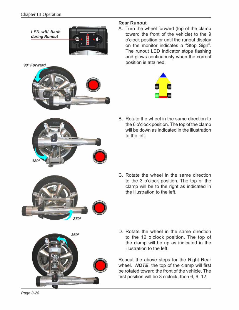
Rear RunoutA. Turn the wheel forward (top of the clamp
toward the front of the vehicle) to the 9 o’clock position or until the runout display on the monitor indicates a “Stop Sign”. The runout LED indicator stops flashing and glows continuously when the correct position is attained.
B. Rotate the wheel in the same direction to the 6 o’clock position. The top of the clamp will be down as indicated in the illustration to the left.
C. Rotate the wheel in the same direction to the 3 o’clock position. The top of the clamp will be to the right as indicated in the illustration to the left.
D. Rotate the wheel in the same direction to the 12 o’clock position. The top of the clamp will be up as indicated in the illustration to the left.
Repeat the above steps for the Right Rear wheel. NOTE, the top of the clamp will first be rotated toward the front of the vehicle. The first position will be 3 o’clock, then 6, 9, 12.
LED will flash during Runout
90º Forward
Page 3-28

Chapter III Operation
Front RunoutWhen compensating the front wheels the companion Pod’s 5 power indicator LEDs will blink for increased visibility if the monitor is not visible.
Compensating the Right Front WheelA. When the Screen prompts the user to pro-
ceed to the first point of rotation, forward 25 degrees, rotate the wheel until the stop sign appears on the screen or the LEDs cease to flash on the companion Pod. Hold steady until prompted to proceed to the next position.
B. Rotate the wheel rearward 25 degrees from vertical or until the screen indicates a stop sign. The companion Pod’s LEDs will also cease to flash.
C. After the readings have been taken at +/- 25 degrees, return the wheel to the 12 o’clock position until prompted to con-tinue.
D. Repeat the above steps on the left front.
Lower Wheels and Bounce (settle) the Suspension The next screen that appears instructs the technician to lower the wheels and bounce or settle the suspension so the vehicle sits at a true ride height. Slip plates should be utilized to provide the necessary sideslip required to return the vehicle to its normal resting position.
After runout compensation you will be prompted to lower the wheels, bounce the suspension and press OK to continue.
LEDs will flash during Runout
Page 3-29
Page 3-30
Chapter III Operation
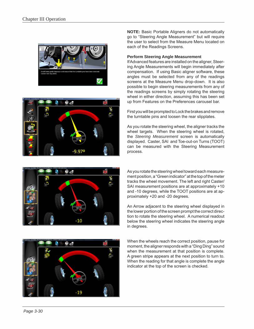
NOTE: Basic Portable Aligners do not automatically go to “Steering Angle Measurement” but will require the user to select from the Measure Menu located on each of the Readings Screens.
Perform Steering Angle MeasurementIf Advanced features are installed on the aligner, Steer-ing Angle Measurements will begin immediately after compensation. If using Basic aligner software, these angles must be selected from any of the readings screens at the Measure Menu drop-down. It is also possible to begin steering measurements from any of the readings screens by simply rotating the steering wheel in either direction, assuming this has been set up from Features on the Preferences carousel bar.
First you will be prompted to Lock the brakes and remove the turntable pins and loosen the rear slipplates.
As you rotate the steering wheel, the aligner tracks the wheel targets. When the steering wheel is rotated, the Steering Measurement screen is automatically displayed. Caster, SAI and Toe-out-on Turns (TOOT) can be measured with the Steering Measurement process.
As you rotate the steering wheel toward each measure-ment position, a “Green indicator” at the top of the meter tracks the wheel movement. The left and right Caster/SAI measurement positions are at approximately +10 and -10 degrees, while the TOOT positions are at ap-proximately +20 and -20 degrees.
An Arrow adjacent to the steering wheel displayed in the lower portion of the screen prompt the correct direc-tion to rotate the steering wheel. A numerical readout below the steering wheel indicates the steering angle in degrees.
When the wheels reach the correct position, pause for moment, the aligner responds with a “Ding Ding” sound when the measurement at that position is complete. A green stripe appears at the next position to turn to. When the reading for that angle is complete the angle indicator at the top of the screen is checked.
Page 3-31
Chapter III Operation
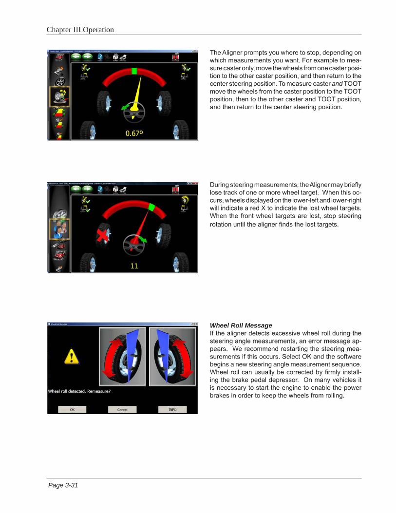
The Aligner prompts you where to stop, depending on which measurements you want. For example to mea-sure caster only, move the wheels from one caster posi-tion to the other caster position, and then return to the center steering position. To measure caster and TOOT move the wheels from the caster position to the TOOT position, then to the other caster and TOOT position, and then return to the center steering position.
During steering measurements, the Aligner may briefly lose track of one or more wheel target. When this oc-curs, wheels displayed on the lower-left and lower-right will indicate a red X to indicate the lost wheel targets. When the front wheel targets are lost, stop steering rotation until the aligner finds the lost targets.
Wheel Roll MessageIf the aligner detects excessive wheel roll during the steering angle measurements, an error message ap-pears. We recommend restarting the steering mea-surements if this occurs. Select OK and the software begins a new steering angle measurement sequence. Wheel roll can usually be corrected by firmly install-ing the brake pedal depressor. On many vehicles it is necessary to start the engine to enable the power brakes in order to keep the wheels from rolling.

Page 3-32
Chapter III Operation
Page 3-32
Chapter III Operation
Page 3-32
Chapter III Operation
Readings ScreenThe Readings screen displays the primary vehicle alignment information in an intuitive, three dimensional format. The screen appears as a vehicle with the body lifted off, viewed from the rear and above. Review the figure above to become familiar with the screen layout and functions.
Each wheel angle has a numeric reading as well as a graphical meter display indicating directional ori-entation and relationship to specifications. Camber meters, located along the top of each tire, have a line that indicates camber relative to the preferred specification. Toe meters, projected onto the ground in front of each tire, have an arrow that indicates the toe angle. Caster is represented by a meter in front of each wheel. The numeric value for caster is directly above the meter. When a meter is green, the reading is within specifications. When the arrow is centered within the green it is at the preferred value. A red meter indicates the reading is out of specification. The red meter contains a green band, indicating the direction of needed change. A gray meter indicates there is no specification for that angle.
All numeric readings on this screen are actual live measurements, including caster. If any angles require correction, make sure the brake pedal depressor is en-gaged and the steering wheel is centered and locked, then simply begin the adjustment. As the angles change the display will update to reflect the new readings. The numeric values change and the meter indicators move in the direction of change. Click on OK to proceed to the next readings screen.
Turn Wheels Straight AheadThe screen then changes to indicate the requirement to turn the wheels to the straight ahead position. Cen-tering the steering allows the geometric center-line to be established for the rear readings which in turn will determine the thrust angle or rolling direction. Thrust Angle is the direction of the vehicle travel determined by the total toe of the rear wheels. The thrust angle is used as a reference when adjusting the front toe so that a straight steering wheel is the end result. Toe error on many rear wheel drive vehicles cannot be cor-rected, creating a dog tracking effect and/or a crooked steering wheel.
If the wheels are already straight ahead this screen will briefly appear and automatically proceed.
Page 3-33
Chapter III Operation
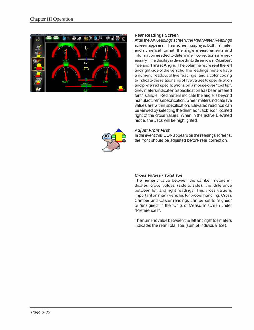
Rear Readings ScreenAfter the All Readings screen, the Rear Meter Readings screen appears. This screen displays, both in meter and numerical format, the angle measurements and information needed to determine if corrections are nec-essary. The display is divided into three rows: Camber, Toe and Thrust Angle. The columns represent the left and right side of the vehicle. The readings meters have a numeric readout of live readings, and a color coding to indicate the relationship of live values to specification and preferred specifications on a mouse over “tool tip”. Grey meters indicate no specification has been entered for this angle. Red meters indicate the angle is beyond manufacturer’s specification. Green meters indicate live values are within specification. Elevated readings can be viewed by selecting the dimmed “Jack” icon located right of the cross values. When in the active Elevated mode, the Jack will be highlighted.
Adjust Front FirstIn the event this ICON appears on the readings screens, the front should be adjusted before rear correction.
Cross Values / Total Toe The numeric value between the camber meters in-dicates cross values (side-to-side), the difference between left and right readings. This cross value is important on many vehicles for proper handling. Cross Camber and Caster readings can be set to “signed” or “unsigned” in the “Units of Measure” screen under “Preferences”.
The numeric value between the left and right toe meters indicates the rear Total Toe (sum of individual toe).
Page 3-34
Chapter III Operation
F1
F2
F3
F4
F5
F6
F7
F8
F9
F10
F11
F12
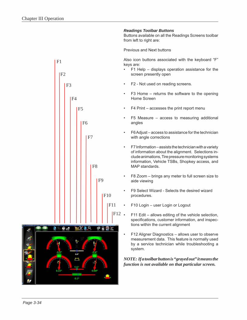
Readings Toolbar Buttons Buttons available on all the Readings Screens toolbar from left to right are:
Previous and Next buttons
Also icon buttons associated with the keyboard “F” keys are:• F1 Help – displays operation assistance for the
screen presently open
• F2 - Not used on reading screens.
• F3 Home – returns the software to the opening Home Screen
• F4 Print – accesses the print report menu
• F5 Measure – access to measuring additional angles
• F6 Adjust – access to assistance for the technician with angle corrections
• F7 Information – assists the technician with a variety of information about the alignment. Selections in-clude animations, Tire pressure monitoring systems information, Vehicle TSBs, Shopkey access, and MAP standards.
• F8 Zoom – brings any meter to full screen size to aide viewing
• F9 Select Wizard - Selects the desired wizard procedures.
• F10 Login – user Login or Logout
• F11 Edit – allows editing of the vehicle selection, specifications, customer information, and inspec-tions within the current alignment
• F12 Aligner Diagnostics – allows user to observe measurement data. This feature is normally used by a service technician while troubleshooting a system.
NOTE: If a toolbar button is “grayed out” it means the function is not available on that particular screen.

Page 3-35
Chapter III Operation
Level and Lock Steering WheelBefore front readings are displayed it is necessary to level the steering wheel and lock it in place using the steering wheel holder. Once these steps are completed press “OK” to move forward.
Front Meter Readings ScreenThe Front Meter Readings screen is similar to the rear. Caster is displayed with the top outside meters. Camber meters are located in the middle of the screen and toe meters are at the bottom. Caster, camber and toe are “live” displays which can be referenced while making adjustments. When measurements are within specification, the center portion of the meter is green. If red is displayed, the readings are outside of specifications. Grey meters indicate this angle has no specification. Elevated camber and caster readings can be viewed by selecting the dimmed “Jack” icon located between the camber meters.
All Readings ScreenAfter Front Readings the final readings screen is All Readings. This screen shows all alignment readings numerically in a chart format. The numbers are color coded to indicate the reading’s relationship to speci-fications.
A scroll bar on the right side of the screen indicates there is more information below. Click on the down arrow of the scroll bar to reveal Front and Rear Diagnostics values (if measured).
Page 3-36
Chapter III Operation
2
1 3
4
5
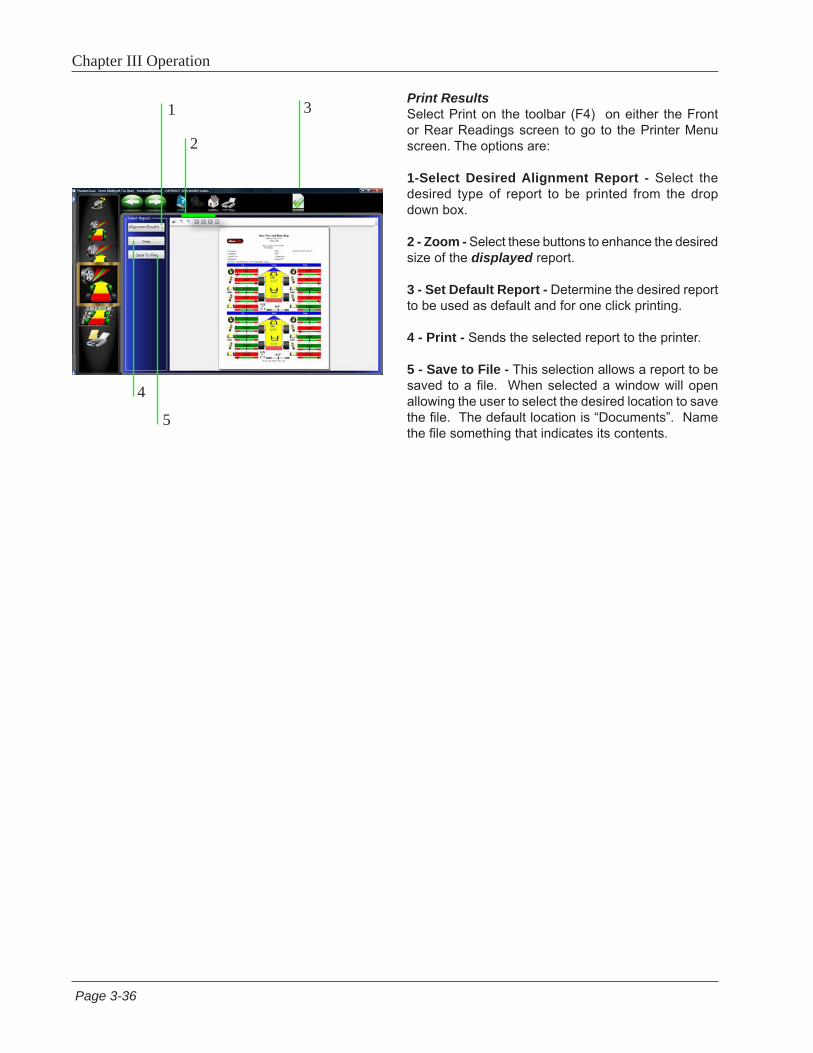
Print ResultsSelect Print on the toolbar (F4) on either the Front or Rear Readings screen to go to the Printer Menu screen. The options are:
1-Select Desired Alignment Report - Select the desired type of report to be printed from the drop down box.
2 - Zoom - Select these buttons to enhance the desired size of the displayed report.
3 - Set Default Report - Determine the desired report to be used as default and for one click printing.
4 - Print - Sends the selected report to the printer.
5 - Save to File - This selection allows a report to be saved to a file. When selected a window will open allowing the user to select the desired location to save the file. The default location is “Documents”. Name the file something that indicates its contents.

Page 3-37
Chapter III Operation
Measure MenuWhen the Measure icon is selected from the toolbar on any readings screen, a screen appears that allows the operator to measure any wheel alignment angle. The icons on this screen are explained below:
• Caster Swing – measures the Caster/SAI and TOOT angles on the turnplates.
• Steering Level Check - Selecting this feature allows the user to check the level of the steering wheel.
• Single Wheel Compensation – instead of the normal compensation sequence, the vehicle can be jacked to allow each wheel to be positioned independently. This is useful if a wheel must be removed during the alignment, for example to install a shim in the rear.
• Vehicle Dimensions (Advanced Option) – Provides additional information about the condition of the ve-hicle’s frame, such as setback and axle offset.
• SAI Only Elevated - Steering Axis Inclination can be measured for diagnosis of certain steering component problems while the front of the vehicle is elevated.
• Max Turns - Is selected to measure the amount of steering angle to the right and to the left. These are generally symmetrical and this test can help determine if a steering linkage is damaged.
• Toe Curve Change – measure the individual wheel toe change as the suspension goes through jounce and rebound.
• Camber at 0 Toe - This process is recommended by some vehicle manufacturers, such as Mercedes Benz. It measures the camber of each front wheel separately with the wheels straight ahead (zero toe).
Page 3-38
Chapter III Operation
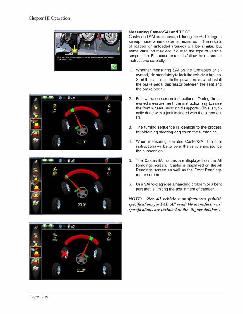
Measuring Caster/SAI and TOOTCaster and SAI are measured during the +\- 10 degree sweep made when caster is measured. The results of loaded or unloaded (raised) will be similar, but some variation may occur due to the type of vehicle suspension. For accurate results follow the on-screen instructions carefully.
1. Whether measuring SAI on the turntables or el-evated, it is mandatory to lock the vehicle’s brakes. Start the car to initiate the power brakes and install the brake pedal depressor between the seat and the brake pedal.
2. Follow the on-screen instructions. During the el-evated measurement, the instruction say to raise the front wheels using rigid supports. This is typi-cally done with a jack included with the alignment lift.
3. The turning sequence is identical to the process for obtaining steering angles on the turntables
4. When measuring elevated Caster/SAI, the final instructions will be to lower the vehicle and jounce the suspension.
5. The Caster/SAI values are displayed on the All Readings screen. Caster is displayed on the All Readings screen as well as the Front Readings meter screen.
6. Use SAI to diagnose a handling problem or a bent part that is limiting the adjustment of camber.
NOTE: Not all vehicle manufacturers publish specifications for SAI. All available manufacturers’ specifications are included in the Aligner database.
Page 3-39
Chapter III Operation
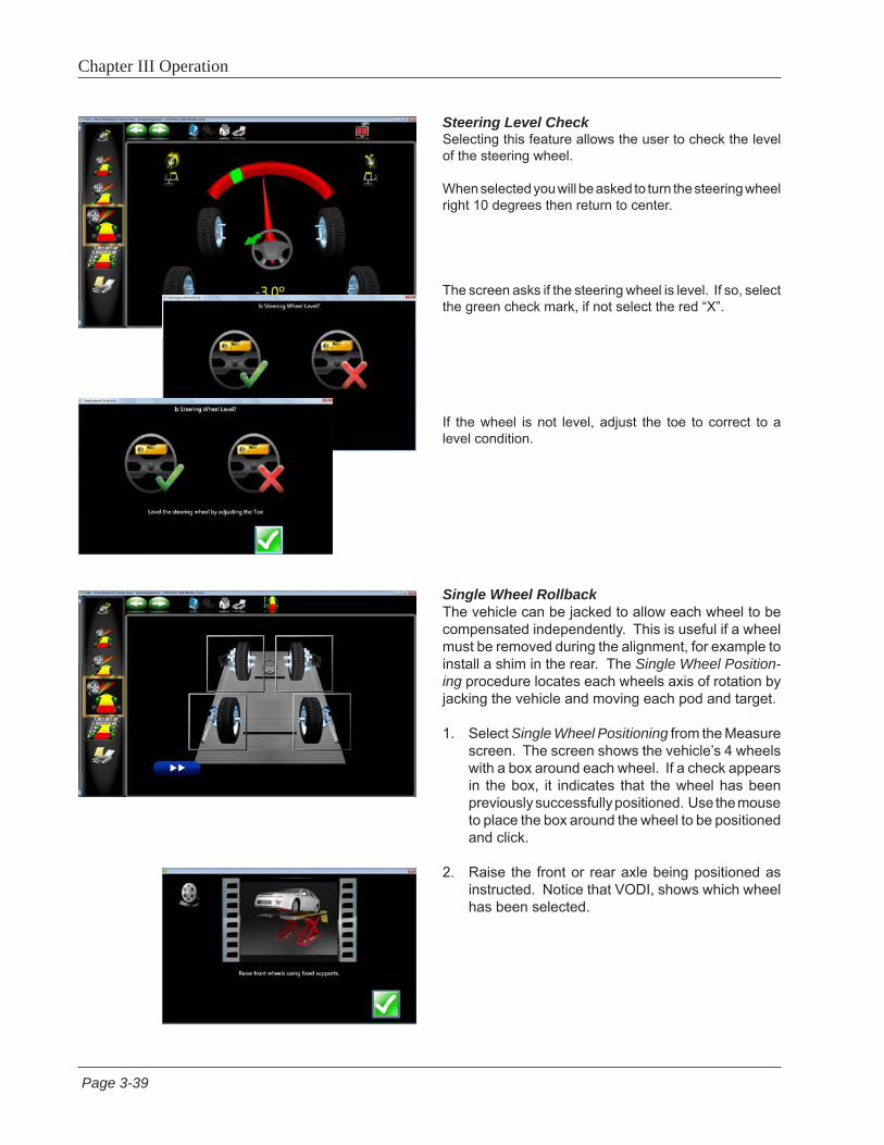
Steering Level CheckSelecting this feature allows the user to check the level of the steering wheel.
When selected you will be asked to turn the steering wheel right 10 degrees then return to center.
The screen asks if the steering wheel is level. If so, select the green check mark, if not select the red “X”.
If the wheel is not level, adjust the toe to correct to a level condition.
Single Wheel RollbackThe vehicle can be jacked to allow each wheel to be compensated independently. This is useful if a wheel must be removed during the alignment, for example to install a shim in the rear. The Single Wheel Position-ing procedure locates each wheels axis of rotation by jacking the vehicle and moving each pod and target.
1. Select Single Wheel Positioning from the Measure screen. The screen shows the vehicle’s 4 wheels with a box around each wheel. If a check appears in the box, it indicates that the wheel has been previously successfully positioned. Use the mouse to place the box around the wheel to be positioned and click.
2. Raise the front or rear axle being positioned as instructed. Notice that VODI, shows which wheel has been selected.
Page 3-40
Chapter III Operation
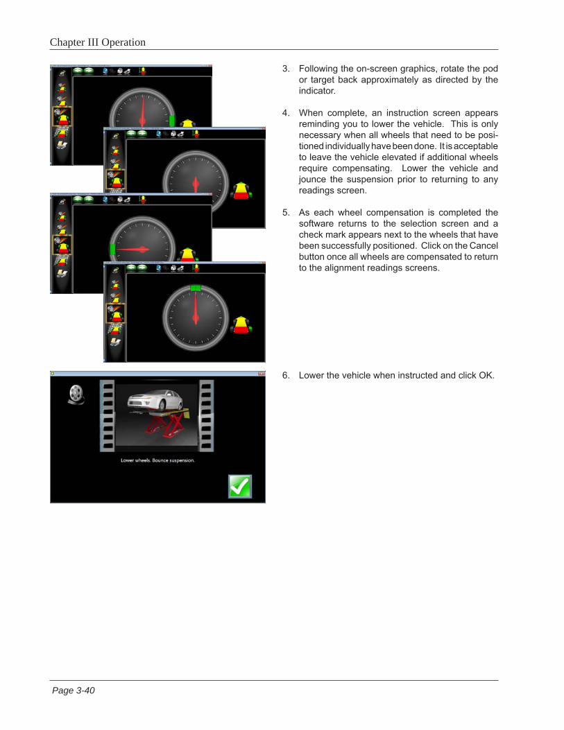
3. Following the on-screen graphics, rotate the pod or target back approximately as directed by the indicator.
4. When complete, an instruction screen appears reminding you to lower the vehicle. This is only necessary when all wheels that need to be posi-tioned individually have been done. It is acceptable to leave the vehicle elevated if additional wheels require compensating. Lower the vehicle and jounce the suspension prior to returning to any readings screen.
5. As each wheel compensation is completed the software returns to the selection screen and a check mark appears next to the wheels that have been successfully positioned. Click on the Cancel button once all wheels are compensated to return to the alignment readings screens.
6. Lower the vehicle when instructed and click OK.
Page 3-41
Chapter III Operation
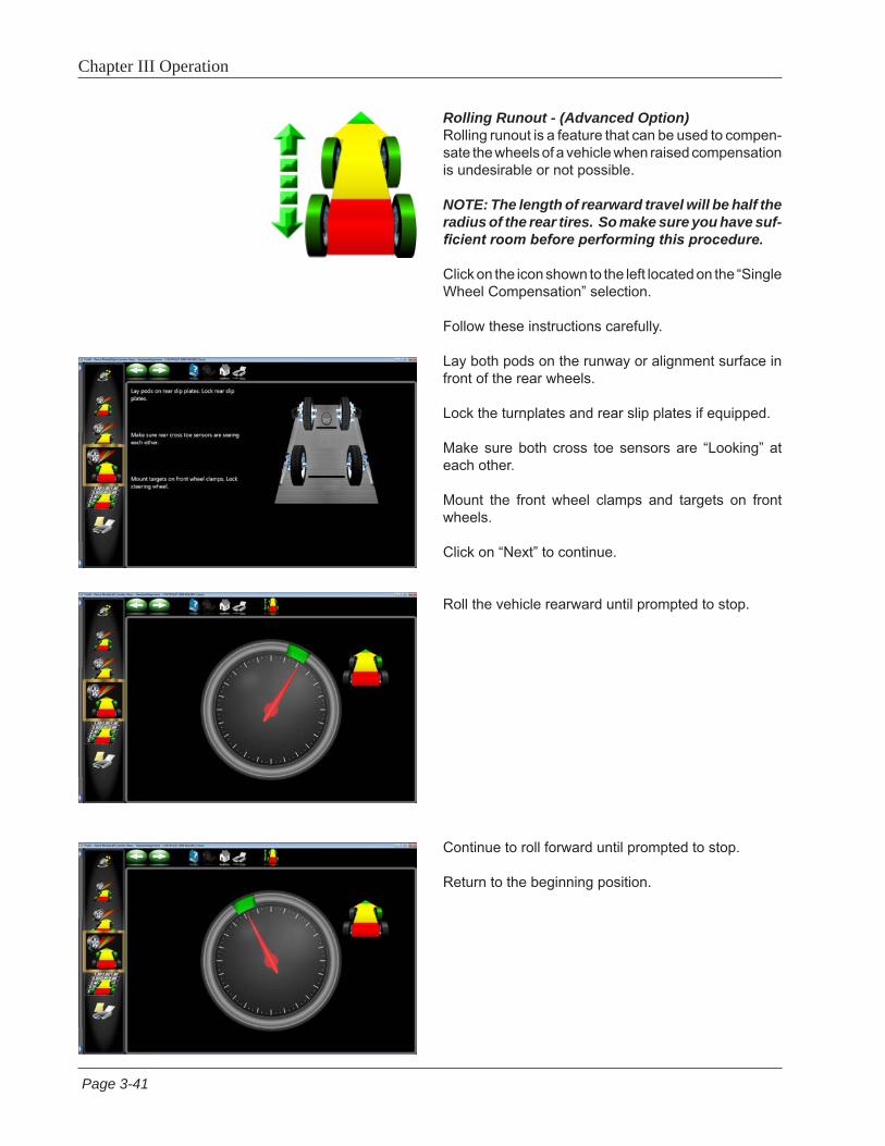
Rolling Runout - (Advanced Option)Rolling runout is a feature that can be used to compen-sate the wheels of a vehicle when raised compensation is undesirable or not possible.
NOTE: The length of rearward travel will be half the radius of the rear tires. So make sure you have suf-ficient room before performing this procedure.
Click on the icon shown to the left located on the “Single Wheel Compensation” selection.
Follow these instructions carefully.
Lay both pods on the runway or alignment surface in front of the rear wheels.
Lock the turnplates and rear slip plates if equipped.
Make sure both cross toe sensors are “Looking” at each other.
Mount the front wheel clamps and targets on front wheels.
Click on “Next” to continue.
Roll the vehicle rearward until prompted to stop.
Continue to roll forward until prompted to stop.
Return to the beginning position.
Page 3-42
Chapter III Operation
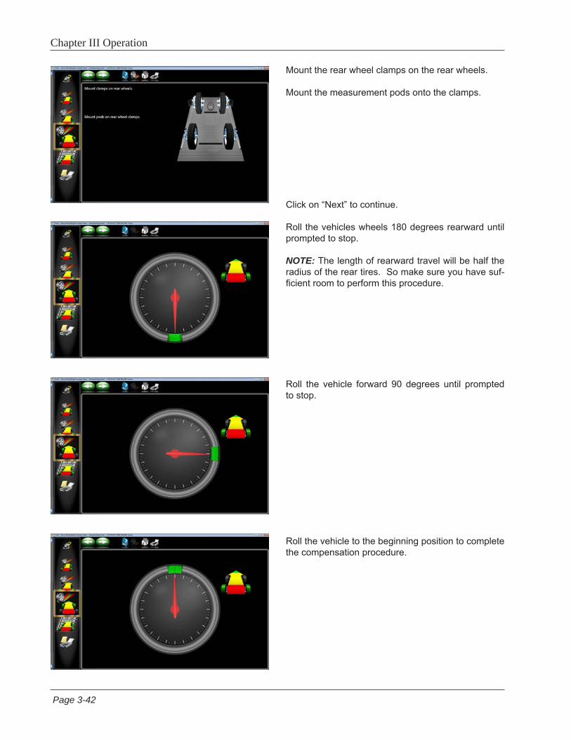
Mount the rear wheel clamps on the rear wheels.
Mount the measurement pods onto the clamps.
Click on “Next” to continue.
Roll the vehicles wheels 180 degrees rearward until prompted to stop.
NOTE: The length of rearward travel will be half the radius of the rear tires. So make sure you have suf-ficient room to perform this procedure.
Roll the vehicle forward 90 degrees until prompted to stop.
Roll the vehicle to the beginning position to complete the compensation procedure.
Page 3-43
Chapter III Operation
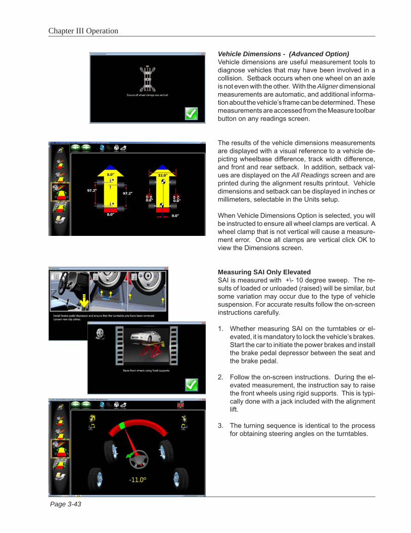
Vehicle Dimensions - (Advanced Option)Vehicle dimensions are useful measurement tools to diagnose vehicles that may have been involved in a collision. Setback occurs when one wheel on an axle is not even with the other. With the Aligner dimensional measurements are automatic, and additional informa-tion about the vehicle’s frame can be determined. These measurements are accessed from the Measure toolbar button on any readings screen.
The results of the vehicle dimensions measurements are displayed with a visual reference to a vehicle de-picting wheelbase difference, track width difference, and front and rear setback. In addition, setback val-ues are displayed on the All Readings screen and are printed during the alignment results printout. Vehicle dimensions and setback can be displayed in inches or millimeters, selectable in the Units setup.
When Vehicle Dimensions Option is selected, you will be instructed to ensure all wheel clamps are vertical. A wheel clamp that is not vertical will cause a measure-ment error. Once all clamps are vertical click OK to view the Dimensions screen.
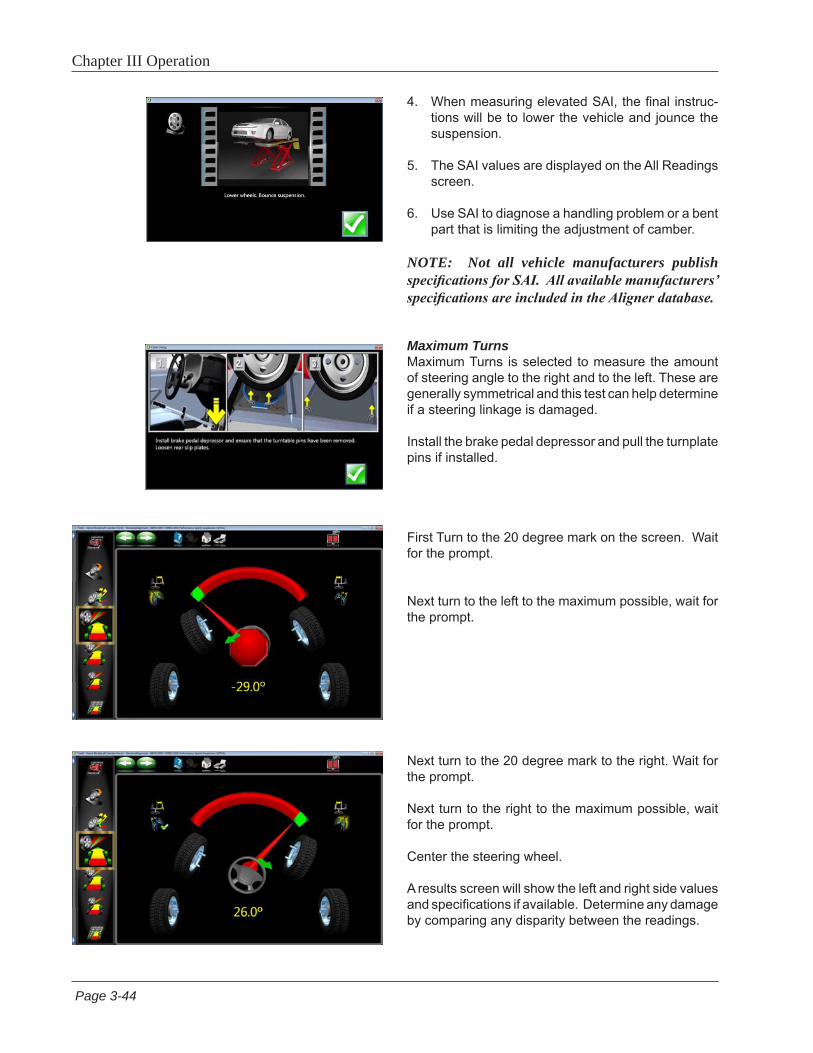
Measuring SAI Only ElevatedSAI is measured with +\- 10 degree sweep. The re-sults of loaded or unloaded (raised) will be similar, but some variation may occur due to the type of vehicle suspension. For accurate results follow the on-screen instructions carefully.
1. Whether measuring SAI on the turntables or el-evated, it is mandatory to lock the vehicle’s brakes. Start the car to initiate the power brakes and install the brake pedal depressor between the seat and the brake pedal.
2. Follow the on-screen instructions. During the el-evated measurement, the instruction say to raise the front wheels using rigid supports. This is typi-cally done with a jack included with the alignment lift.
3. The turning sequence is identical to the process for obtaining steering angles on the turntables.
Page 3-44
Chapter III Operation
4. When measuring elevated SAI, the final instruc-tions will be to lower the vehicle and jounce the suspension.
5. The SAI values are displayed on the All Readings screen.
6. Use SAI to diagnose a handling problem or a bent part that is limiting the adjustment of camber.
NOTE: Not all vehicle manufacturers publish specifications for SAI. All available manufacturers’ specifications are included in the Aligner database.
Maximum TurnsMaximum Turns is selected to measure the amount of steering angle to the right and to the left. These are generally symmetrical and this test can help determine if a steering linkage is damaged.
Install the brake pedal depressor and pull the turnplate pins if installed.
First Turn to the 20 degree mark on the screen. Wait for the prompt.
Next turn to the left to the maximum possible, wait for the prompt.
Next turn to the 20 degree mark to the right. Wait for the prompt.
Next turn to the right to the maximum possible, wait for the prompt.
Center the steering wheel.
A results screen will show the left and right side values and specifications if available. Determine any damage by comparing any disparity between the readings.

Page 3-45
Chapter III Operation
Toe Curve Change This feature allows measurement of individual wheel toe change as the suspension system goes through jounce and rebound (spring compression and expan-sion). An excessive amount of toe change can cause premature tire wear. A large change on only one side can cause “bump steer”, a dangerous condition causing the vehicle to rapidly change directions when bumps are encountered. While there are no specifications for the amount of change, it should be fairly small, and a comparison of left and right wheels can assist in diag-nosing defective steering system components.
Follow the on-screen instructions carefully to move the suspension through a 60mm (2.3”) travel. This can be done by pulling down or pushing up the suspension.
Use a ruler or tape measure to observe the proper amount of frame movement. Select OK when com-pleted to display the results.
TIP: On cars with rack and pinion steering, a bump steer condition is usually created by worn rack mount-ing bushings that allow the entire rack to shift when bumps are hit.
Camber at Zero ToeThis routine measures camber on the left and right front wheels individually at zero toe. This is the recommended procedure for vehicles with high caster specifications, such as Mercedes-Benz.
The procedure is as follows:
1. Select Camber at Zero Toe from Measure Screen.
2. Using the on-screen meter, turn the left wheel towards the center until the meter turns green.
3. Press OK to continue.
4. Repeat this process for the right wheel. Click OK to continue.
5. The results are displayed above the wheel graphics. Click “Next” to return to the readings screen.

Page 3-46
Chapter III Operation
Adjust MenuOne of the most powerful features of the Aligner Series is the assistance given to the alignment technician when performing adjustments on a vehicle. These features are on the Adjust menu, and are accessed through the Adjust icon, located on all Readings Screens.
Caster, Camber and Toe Adjust on Turnplates - This feature allows “live” adjustment of front suspension components.
Caster, Camber and Toe Adjust Elevated - This feature allows “live” adjustment of front suspension components while in the raised position.
Rear Camber and Toe Adjust Elevated - This feature allows “live” adjustment of rear suspension components while in the raised position.
EZ Toe – This software routine is a method of setting front toe while steered from straight ahead, making it easier to adjust and obtain straight steering wheels.
Shims and Kits – Many front wheel drive cars use a shim on the rear axle/spindle to adjust camber and/or toe. This program determines the proper shim to use.
A-Arm Adjust – for vehicles whose caster and camber adjustments are located on the suspension A-Arm, this selection allows both angles to be corrected simul-taneously.
Wheel Off Caster, Camber, and Toe Adjust - This feature allows the operator to remove the wheel and attach the clamp/target assembly directly to a brake rotor for easier access to adjustment of certain angles.
Wheel Off Rear Camber, and Toe Adjust - This feature allows the operator to remove the rear wheel and attach the clamp/pod assembly directly to a brake rotor for easier access to adjustment of certain angles.
Offset Cam Bushing - Many 2 and 4 -wheel drive trucks utilize offset sleeves and inserts around the upper or lower ball joints to adjust the caster and camber angles.
Cradle Adjust – Assist with the adjustment of the engine cradle on many front wheel drive cars. Adjust Drag Link – Assists with steer direction and straight steering wheel when performing toe adjustments on trucks with a drag link adjustment.
Single Tie Rod Adjust – helps with vehicles having a single tie rod toe ad-juster.
Each of the Adjust Menu selections are described in the following pages.

Page3-47
Chapter III Operation
Adjust Caster and/or Camber, and Toe ElevatedAfter selecting this icon, instructions appear in prepara-tion for the adjustment.• Install brake pedal depressor• Remove pins from turnplates and rear slip-plates• Press OK
This screen now appears alerting you to raise the axle to be adjusted• Raise front wheels using rigid supports• Press OK
IMPORTANT!Follow all on-screen instructions carefully. Incor-rect adjustment readings are possible if these steps are ignored.
When OK is pressed, the Front Readings display appears with a highlighted Jack indicating raised condition.
Adjust caster, camber or toe as required while view-ing the screen. As adjustments are made, the meter movements and numeric values change. The meters are color coded to show the readings’ relationship to specifications if selected.
Once the adjustments are completed, press OK. Post-adjustment instructions will be displayed: • Lower wheels. Bounce suspension• Unlock the brakes• Press OK
The software automatically returns to the readings screen where you started.

Page 3-48
Chapter III Operation
EZ ToeThis software routine is a an improved method of setting front toe, making it easier to obtain straight steering wheels. It also makes it possible to adjust toe with the wheels turned at any angle left or right, an aide when setting toe on cars with firewall mounted rack and pinion units.
Use the following procedures:
1. Perform all alignment steps normally used to obtain alignment readings. Correct any misalignment in the rear as well as front caster and/or camber.
2. Select the EZ Toe icon from the Adjust screen.
3. Level the vehicle steering wheel, Select OK.
4. Steer the right wheel to the adjust position. Select Next.
5. The next screen shows a meter indicating the amount of toe change needed for the right wheel.
6. Adjust the right tie rod until the meter needle is in the green. Select Next after completion.
7. Follow the same procedures for the left wheel.
8. Select Next when the left toe adjustment is made.
9. Return to the Front Readings screen and recheck toe and steering wheel position.
NOTE: If using EZ Toe at a large turn angle, it will be necessary to use the Steering Wheel Clamp to hold the linkage steady at that position.

Page3-49
Chapter III Operation
Shims and Kits Many front wheel drive vehicles utilize aftermarket shims to correct front and rear camber and/or toe. This correction is achieved by placing the shim between the rear axle and the spindle.
When a vehicle that utilizes rear shims is accessed from the specification database, the technician can use the aligner to determine the proper shim to correct a misalignment. From the “Adjust” drop down menu select Shims and Kits.
At this point the computer will examine the live camber and toe readings, compare them to preferred specifi-cation, and calculate the amount of change needed. It will then recommend the shim needed to make this correction. The screen to the left will be displayed.
Default Part VendorDetermine the desired part vendor to select as the default aftermarket supplier. This selection will vary location to location and upon the Technicians prefer-ences.
The part number of the shim or adjuster kit is automati-cally selected and displayed dependant on the vehicle selected and the amount of correction required.
Highlight one of the part numbers displayed, then click on the “Info” ICON to invoke a screen describing the correct orientation of shims or other corrective after-market parts. The “Info” ICON can be selected from several places of the screen. If highlighted, information is available. See sample screen at left.
Installation video and detailed Instructions may also be available.
Click the “Aftermarket Tools Available” ICON to view tools required for the specific procedure if available.

Page 3-50
Chapter III Operation
Adjust A-ArmsMany vehicles have adjustment provisions for caster and camber located on the suspension A-Arm (control arm), either on the upper or lower arm. The adjustments may be made with shims, eccentric cams, or slots in the frame. Both angles are easily corrected to manufacturer’s specification using the Adjust A-Arm icon.
First, a screen instructs the operator to apply the brake pedal depressor (important) and remove the lock pins from the turntables. Select OK.
The next screen, A-Arm Adjust, allows selection of the location of the adjustable A-Arm and whether the corrections will be made on the turntables or elevated. Examine the vehicle for the location of the adjusters. It does not matter whether the a-arms have shims, slots, or cams.
Select to adjust upper A-Arm or Lower A-Arm on the Adjust A-Arm screen.
The icon looks like that to the left. Selecting switches from upper to lower and back.
The adjustment screen contains a graphic of the left and right side a-arm along with two “Slide” meters for each. These meters represent the movement of the front and rear of the a-arm, and their relationship to the desired readings. Move each side of the a-arm by adding/removing shims, loosening the bolts and sliding the arm, or turning the eccentric cams, until each meter indicator is centered in the meter – this is the desired value for both caster and camber. Press Next when complete.
Follow any additional instructions if required such as lower and bouncing the suspension.

Page3-51
Chapter III Operation
Wheel Off Caster, Camber, Toe AdjustFollow the Same procedures as outlined in Caster, Camber and Toe Elevated above but with the Wheel-off option.
First install the brake pedal depressor and remove the lock pins from the turn plates and slipplates.
Raise the vehicle using rigid supports.
Remove the wheels that require service and mount the clamp target assembly to the brake rotor.
The “Raised Jack” icon on the readings screen indi-cates the vehicle should be in the raised position for these adjustments.
Make “Live” adjustments as required to correct angles to specification.
Re-Mount wheels and Mount clamps.
NOTE: The wheel(s) that have had the clamp assemble removed will need to be re-compensated.
Lower the vehicle and bounce the suspension.

Page 3-52
Chapter III Operation
Offset Cams and BushingsMany Ford 2-wheel drive trucks and many Ford/GM/Dodge 4-wheel drive trucks utilize offset sleeves and inserts around the upper or lower ball joints to adjust the caster and camber angles.
The program compares the current reading for caster and camber with the preferred specification, displaying the meters on-screen for reference. The required sleeve/insert to correct the angles is shown below the meters, along with the orientation of the slot. Proper orientation of the slot insures the correct amount of caster and camber is obtained from the sleeve/insert.
The calculations assume the current sleeve/insert is a ZERO (no offset). If it is not, examine the slot orientation to determine if the previous installation corrected camber or caster. Enter the value of the old sleeve/insert in the box below either caster or camber, whichever most accurately reflects the orientation of the slot.
Note: Whenever there is a sleeve/insert installed that is not zero, it is difficult to determine its affect on the calculation of the new required sleeve/insert. It is a good idea to have a few zero sleeves available to install in the truck and re-measure caster to get a true initial reading.
Cradle Adjust (Optional Advanced Feature)Cradle adjustment is a growing necessity for front wheel drive vehicles. Many front wheel drive vehicles are designed where the engine cradle also serves as the attachment point for the lower pivots of the suspension system. This assembly is bolted to the sub-frame as a unit from the bottom of the vehicle. The assembly must be properly aligned with the sub-frame to assure that front alignment is maintained.
A closer look shows that the lower control arms are bolted to the engine cradle. The control arm is attached to the spindle through the lower ball joint. The strut is attached to the top of the spindle and is then attached to the body via the upper strut mount to complete the suspension steering axis.

Page3-53
Chapter III Operation
The engine cradle can potentially move side to side, changing the camber and SAI angles. Prior to beginning a cradle adjustment, examine the left and right camber values. If one side has excessive positive camber and the other side excessive negative, this vehicle is a candidate for cradle adjustment.
Consult the vehicle service manual for details on how to loosen the engine cradle.
To adjust a cradle using the Aligner, click on the Cradle Adjust icon on the Adjust Screen.
Install Brake pedal depressor and remove turntable and slipplate pins. Click “OK” when ready.
Raise front wheels using fixed supports. Click “OK”.
The Cradle Adjust screen has a graphic of the cradle showing the direction of needed movement. A meter display determines exact placement. Loosen the cradle and slide in the direction of the arrow until the meter indicator is centered – this is the ideal placement of the cradle. In addition, live caster and SAI readings are shown for reference or for making a minor caster correction.
When Complete, lower and bounce suspension.
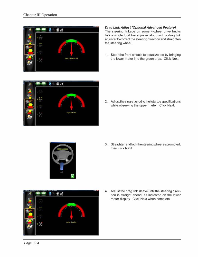
Page 3-54
Chapter III Operation
Drag Link Adjust (Optional Advanced Feature)The steering linkage on some 4-wheel drive trucks has a single total toe adjuster along with a drag link adjuster to correct the steering direction and straighten the steering wheel.
1. Steer the front wheels to equalize toe by bringing the lower meter into the green area. Click Next.
2. Adjust the single tie rod to the total toe specifications while observing the upper meter. Click Next.
3. Straighten and lock the steering wheel as prompted, then click Next.
4. Adjust the drag link sleeve until the steering direc-tion is straight ahead, as indicated on the lower meter display. Click Next when complete.
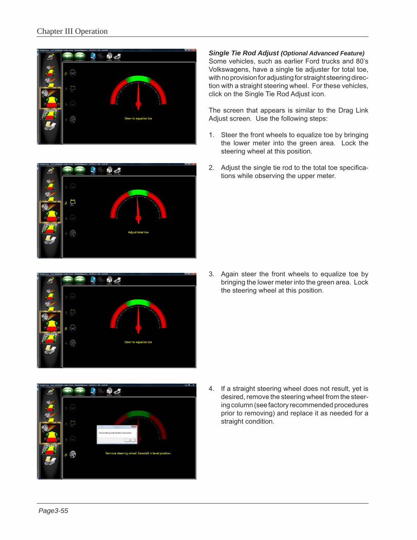
Page3-55
Chapter III Operation
Single Tie Rod Adjust (Optional Advanced Feature)Some vehicles, such as earlier Ford trucks and 80’s Volkswagens, have a single tie adjuster for total toe, with no provision for adjusting for straight steering direc-tion with a straight steering wheel. For these vehicles, click on the Single Tie Rod Adjust icon.
The screen that appears is similar to the Drag Link Adjust screen. Use the following steps:
1. Steer the front wheels to equalize toe by bringing the lower meter into the green area. Lock the steering wheel at this position.
2. Adjust the single tie rod to the total toe specifica-tions while observing the upper meter.
3. Again steer the front wheels to equalize toe by bringing the lower meter into the green area. Lock the steering wheel at this position.
4. If a straight steering wheel does not result, yet is desired, remove the steering wheel from the steer-ing column (see factory recommended procedures prior to removing) and replace it as needed for a straight condition.
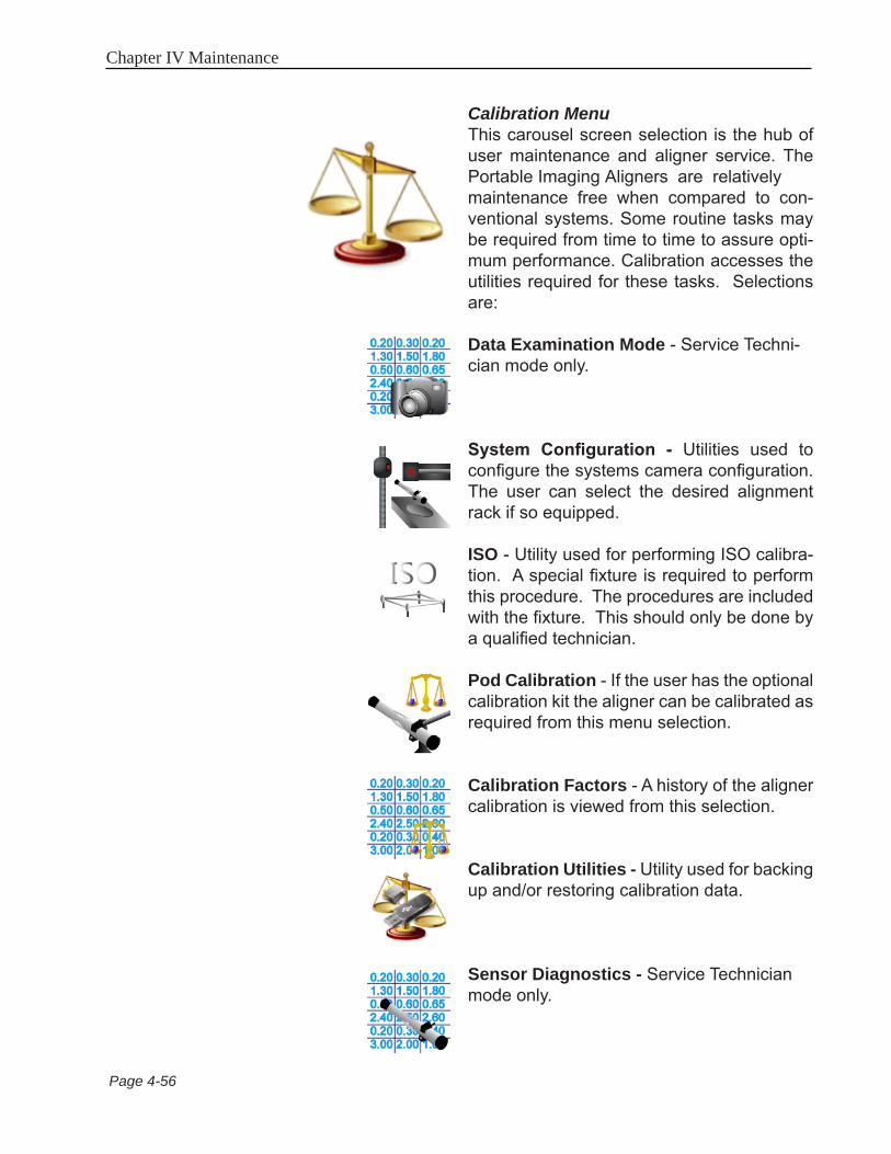
Chapter IV Maintenance
Page 4-56
Calibration MenuThis carousel screen selection is the hub of user maintenance and aligner service. The Portable Imaging Aligners are relatively maintenance free when compared to con-ventional systems. Some routine tasks may be required from time to time to assure opti-mum performance. Calibration accesses the utilities required for these tasks. Selections are:
Data Examination Mode - Service Techni-cian mode only.
System Configuration - Utilities used to configure the systems camera configuration. The user can select the desired alignment rack if so equipped.
ISO - Utility used for performing ISO calibra-tion. A special fixture is required to perform this procedure. The procedures are included with the fixture. This should only be done by a qualified technician.
Pod Calibration - If the user has the optional calibration kit the aligner can be calibrated as required from this menu selection.
Calibration Factors - A history of the aligner calibration is viewed from this selection.
Calibration Utilities - Utility used for backing up and/or restoring calibration data.
Sensor Diagnostics - Service Technician mode only.
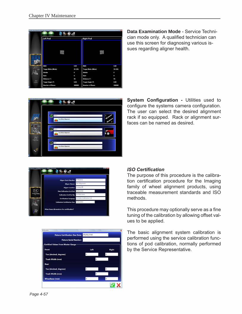
Chapter IV Maintenance
Page 4-57
Data Examination Mode - Service Techni-cian mode only. A qualified technician can use this screen for diagnosing various is-sues regarding aligner health.
System Configuration - Utilities used to configure the systems camera configuration. The user can select the desired alignment rack if so equipped. Rack or alignment sur-faces can be named as desired.
ISO CertificationThe purpose of this procedure is the calibra-tion certification procedure for the Imaging family of wheel alignment products, using traceable measurement standards and ISO methods.
This procedure may optionally serve as a fine tuning of the calibration by allowing offset val-ues to be applied.
The basic alignment system calibration is performed using the service calibration func-tions of pod calibration, normally performed by the Service Representative.
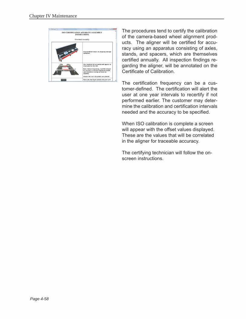
Chapter IV Maintenance
Page 4-58
The procedures tend to certify the calibration of the camera-based wheel alignment prod-ucts. The aligner will be certified for accu-racy using an apparatus consisting of axles, stands, and spacers, which are themselves certified annually. All inspection findings re-garding the aligner, will be annotated on the Certificate of Calibration.
The certification frequency can be a cus-tomer-defined. The certification will alert the user at one year intervals to recertify if not performed earlier. The customer may deter-mine the calibration and certification intervals needed and the accuracy to be specified.
When ISO calibration is complete a screen will appear with the offset values displayed. These are the values that will be correlated in the aligner for traceable accuracy.
The certifying technician will follow the on-screen instructions.

Chapter IV Maintenance
Page 4-59
CalibrationBefore an alignment is performed the aligner must be calibrated to the rack that alignments are done on. Although the unit is shipped from the factory calibrated to zero we can not assume that all racks are exactly level in the field.
Raise the alignment rack to a comfortable working 1. height.
From the Main Menu select the “Calibration” Icon 2. from the Main Carousel.
A “Warning” message appears instructing the user 4. that the calibration process should be performed by trained individuals. Click on “OK” to continue.
Select the Rack to be calibrated on.5.
Place the calibration bar and stands, (calibration 6. kit number EAK0222J02A) on the rear of the rack as shown in the figure. Place the bar so that the numbers stamped on the bar are on the left side runway.
NOTE: IT WILL BE NECESSARY TO INSTALL THE CALIBRATION BAR ADAPTER (EAK0289J42A)ON THE END OF THE CALIBRATION BAR WITH THE FLAT SPOTS. THIS WILL ENSURE A SMOOTH ROTATION OF THE BAR DURING CALIBRATION
Install the EAK0289J42A Bar Adapter on the 7. end with the numbers with the set screws at 12 o’clock.
Select the Pod Calibration button from the 3. Calibration Carousel.
Rear Calibration

Chapter IV Maintenance
Page 4-60
Place the left pod on the calibration bar so that the 8. boom faces the rear of the rack.
Place the right pod on the calibration bar so that 9. the boom faces the rear of the rack.
Place the targets on the front turn plates and orient 10. them so that they are facing the pods. It will be necessary to leave the targets mounted to the wheel clamps.
With the Pods locked on the bar rotate the bar 11. FORWARD 90° to align the needle within the green area. A Stop sign will appear indicating to hold the position until instructed.
Continue to rotate the bar 12. FORWARD to 180° to align the needle within the green area. A Stop sign will appear indicating to hold the position until instructed.
Continue through the process stopping at each of 13. the four positions.

Chapter IV Maintenance
Page 4-61
FRONT CALIBRATION
Place the targets in the bar so that the targets face 1. the rear of the rack.
Place the Pods on the rear of the rack so that the 2. boom of the pod points towards the rear of the rack.
The unit will prompt the user to rotate the bar so 3. that the targets rotated FORWARD 25°. A stop signal will appear.
After the information is taken the user will be 4. prompted to rotate the targets 25° REARWARD from vertical. A stop sign indicates when measurements are being taken.
Rotate the bar back to vertical to complete target 5. calibration.
When the calibration is complete the user will 6. need to press <OK> button to store the calibration data.
CALIBRATION COMPLETE7.
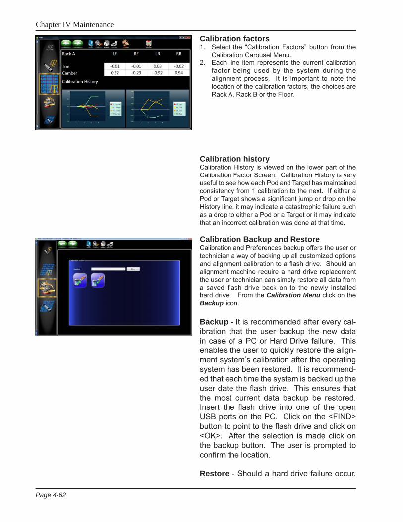
Chapter IV Maintenance
Page 4-62
Calibration factorsSelect the “Calibration Factors” button from the 1. Calibration Carousel Menu.Each line item represents the current calibration 2. factor being used by the system during the alignment process. It is important to note the location of the calibration factors, the choices are Rack A, Rack B or the Floor.
Calibration historyCalibration History is viewed on the lower part of the Calibration Factor Screen. Calibration History is very useful to see how each Pod and Target has maintained consistency from 1 calibration to the next. If either a Pod or Target shows a significant jump or drop on the History line, it may indicate a catastrophic failure such as a drop to either a Pod or a Target or it may indicate that an incorrect calibration was done at that time.
Calibration Backup and RestoreCalibration and Preferences backup offers the user or technician a way of backing up all customized options and alignment calibration to a flash drive. Should an alignment machine require a hard drive replacement the user or technician can simply restore all data from a saved flash drive back on to the newly installed hard drive. From the Calibration Menu click on the Backup icon.
Backup - It is recommended after every cal-ibration that the user backup the new data in case of a PC or Hard Drive failure. This enables the user to quickly restore the align-ment system’s calibration after the operating system has been restored. It is recommend-ed that each time the system is backed up the user date the flash drive. This ensures that the most current data backup be restored. Insert the flash drive into one of the open USB ports on the PC. Click on the <FIND> button to point to the flash drive and click on <OK>. After the selection is made click on the backup button. The user is prompted to confirm the location.
Restore - Should a hard drive failure occur,

Chapter IV Maintenance
Page 4-63
simply install the last known alignment cali-bration and preference data disk and restore the aligner back to the user’s preferred pref-erence.
NOTE: IF ThE OPERATOR IS NOT SURE IF ThE SAVED DATA ON ThE FLASh DRIVE IS CURRENT IT IS RECOMMENDED ThAT A CALIBRATION BE PERFORMED. FAILURE TO hAVE ACCURATE CALIBRATION DATA CAN AND WILL CAUSE ExCESSIVE TIRE WEAR.
Sensor DiagnosticsThis is a Service Technician mode only shown only here for reference.

NOTES:

NOTES:

USAEquipment Services
309 Exchange AvenueConway, Arkansas 72032
Tel.: (800) 362-8326 o (501) 450-1500Fax: (501) 450-1585
ZEEWA555P4.. 09/29/10...wdc...copyright 2010 Snap-on Equipment All Rights Reserved
Notice: The information contained in this document is subject to change without notice. Snap-on Equipment makes no warranty with regard to this material, shall not be liable for errors contained herein or for incidental consequential damages in connection with furnishings, performance, or use of this material.
This document contains proprietary information which is protected by copyright and patents. All rights are reserved. No part of this document may be photocopied, reproduced, or translated without prior written consent of Snap-on Equipment.