Operator’s Manual POWER MIG (140, 180 MODELS) - …adfwelding.com/download/product specs/Lincoln...
56
Operator’s Manual POWER MIG ® (140, 180 MODELS) Register your machine: www.lincolnelectric.com/register Authorized Service and Distributor Locator: www.lincolnelectric.com/locator IM890-A | Issue Date Nov- 13 © Lincoln Global, Inc. All Rights Reserved. For use with machines having Code Numbers: 11254, 11255, 11256, 11257 and 11444 LINCOLN ELECTRIC Save for future reference Date Purchased Code: (ex: 10859) Serial: (ex: U1060512345)
Transcript of Operator’s Manual POWER MIG (140, 180 MODELS) - …adfwelding.com/download/product specs/Lincoln...

Operator’s Manual
POWER MIG ®(140, 180 MODELS)
Register your machine: www.lincolnelectric.com/register
Authorized Service and Distributor Locator: www.lincolnelectric.com/locator
IM890-A | Issue D ate Nov- 13
© Lincoln Global, Inc. All Rights Reserved.
For use with machines having Code Numbers:
11254, 11255, 11256, 11257 and11444
LINCOLN
ELECTRIC
Save for future reference
Date Purchased
Code: (ex: 10859)
Serial: (ex: U1060512345)
THANK YOU FOR SELECTING A QUALITY PRODUCT BY LINCOLN ELEC TRIC.
PLEASE EXAMINE CARTON AND EQUIPMENT FORDAMAGE IMMEDIATELY
When this equipment is shipped, title passes to the purchaser uponreceipt by the carrier. Consequently, Claims for material damaged inshipment must be made by the purchaser against the transportationcompany at the time the shipment is received.
SAFETY DEPENDS ON YOU
Lincoln arc welding and cutting equipment is designed and built withsafety in mind. However, your overall safety can be increased byproper installation ... and thoughtful operation on your part. DO NOT INSTALL, OPERATE OR REPAIR THIS EQUIPMENT WITHOUT READING THIS MANUAL AND THE SAFETY PRECAUTIONSCONTAINED THROUGHOUT. And, most importantly, think before youact and be careful.
This statement appears where the information must be followedexactly to avoid serious personal injury or loss of life.
This statement appears where the information must be followed toavoid minor personal injury or damage to this equipment.
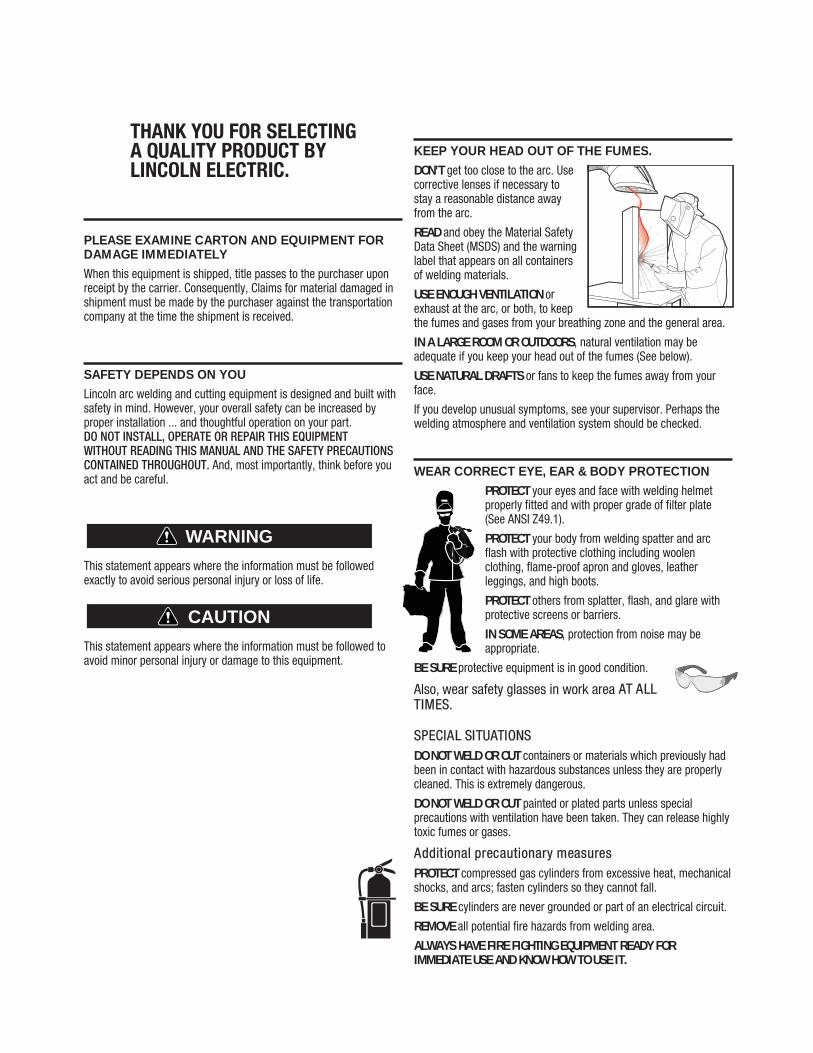
KEEP YOUR HEAD OUT OF THE FUMES.
DON’T get too close to the arc. Usecorrective lenses if necessary tostay a reasonable distance awayfrom the arc.
READ and obey the Material SafetyData Sheet (MSDS) and the warninglabel that appears on all containersof welding materials.
USE ENOUGH VENTILATION orexhaust at the arc, or both, to keepthe fumes and gases from your breathing zone and the general area.
IN A LARGE ROOM OR OUTDOORS, natural ventilation may beadequate if you keep your head out of the fumes (See below).
USE NATURAL DRAFTS or fans to keep the fumes away from yourface.
If you de velop unusual symptoms, see your supervisor. Perhaps thewelding atmosphere and ventilation system should be checked.
WEAR CORRECT EYE, EAR & BODY PROTECTION
PROTECT your eyes and face with welding helmetproperly fitted and with proper grade of filter plate(See ANSI Z49.1).
PROTECT your body from welding spatter and arcflash with protective clothing including woolenclothing, flame-proof apron and gloves, leatherleggings, and high boots.
PROTECT others from splatter, flash, and glare withprotective screens or barriers.
IN SOME AREAS, protection from noise may beappropriate.
BE SURE protective equipment is in good condition.
Also, wear safety glasses in work area AT ALLTIMES.
SPECIAL SITUATIONSDO NOT WELD OR CUT containers or materials which previously hadbeen in contact with hazardous substances unless they are properlycleaned. This is extremely dangerous.
DO NOT WELD OR CUT painted or plated parts unless specialprecautions with ventilation have been taken. They can release highlytoxic fumes or gases.
Additional precautionary measuresPROTECT compressed gas cylinders from excessive heat, mechanicalshocks, and arcs; fasten cylinders so they cannot fall.
BE SURE cylinders are never grounded or part of an electrical circuit.
REMOVE all potential fire hazards from welding area.
ALWAYS HAVE FIRE FIGHTING EQUIPMENT READY FORIMMEDIATE USE AND KNOW HOW TO USE IT.
WARNING
CAUTION
SECTION A:WARNINGS
CALIFORNIA PROPOSITION 65 WARNINGS
Diesel EnginesDiesel engine exhaust and some of its constituents are known to the State of California to cause cancer, birth defects, and otherreproductive harm.
Gasoline EnginesThe engine exhaust from this product contains chemicals known to the State of California to cause cancer, birth defects, or otherreproductive harm.
ARC WELDING CAN BE HAZARDOUS. PROTECTYOURSELF AND OTHERS FROM POSSIBLE SERIOUSINJURY OR DEATH. KEEP CHILDREN AWAY. PACE-MAKER WEARERS SHOULD CONSULT WITH THEIRDOCTOR BEFORE OPERATING.
Read and understand the following safety highlights. For additionalsafety information, it is strongly recommended that you purchase acopy of “Safety in Welding & Cutting - ANSI Standard Z49.1” from theAmerican Welding Society, P.O. Box 351040, Miami, Florida 33135 orCSA Standard W117.2-1974. A Free copy of “Arc Welding Safety”booklet E205 is available from the Lincoln Electric Company, 22801St. Clair Avenue, Cleveland, Ohio 44117-1199.
BE SURE THAT ALL INSTALLATION, OPERATION,MAINTENANCE AND REPAIR PROCEDURES AREPERFORMED ONLY BY QUALIFIED INDIVIDUALS.
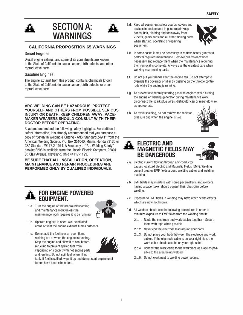
FOR ENGINE POWEREDEQUIPMENT.
1.a. Turn the engine off before troubleshootingand maintenance work unless themaintenance work requires it to be running.
1.b. Operate engines in open, well-ventilatedareas or vent the engine exhaust fumes outdoors.
1.c. Do not add the fuel near an open flamewelding arc or when the engine is running.Stop the engine and allow it to cool beforerefueling to prevent spilled fuel fromvaporizing on contact with hot engine partsand igniting. Do not spill fuel when fillingtank. If fuel is spilled, wipe it up and do not start engine untilfumes have been eliminated.
1.d. Keep all equipment safety guards, covers anddevices in position and in good repair.Keephands, hair, clothing and tools away from V-belts, gears, fans and all other moving partswhen starting, operating or repairingequipment.
1.e. In some cases it may be necessary to remove safety guards toperform required maintenance. Remove guards only whennecessary and replace them when the maintenance requiringtheir removal is complete. Always use the greatest care whenworking near moving parts.
1.f. Do not put your hands near the engine fan. Do not attempt tooverride the governor or idler by pushing on the throttle controlrods while the engine is running.
1.g. To prevent accidentally starting gasoline engines while turningthe engine or welding generator during maintenance work,disconnect the spark plug wires, distributor cap or magneto wireas appropriate.
1.h. To avoid scalding, do not remove the radiatorpressure cap when the engine is hot.
ELECTRIC ANDMAGNETIC FIELDS MAYBE DANGEROUS
2.a. Electric current flowing through any conductorcauses localized Electric and Magnetic Fields (EMF). Weldingcurrent creates EMF fields around welding cables and weldingmachines
2.b. EMF fields may interfere with some pacemakers, and weldershaving a pacemaker should consult their physician beforewelding.
2.c. Exposure to EMF fields in welding may have other health effectswhich are now not known.
2.d. All welders should use the following procedures in order tominimize exposure to EMF fields from the welding circuit:
2.d.1. Route the electrode and work cables together - Securethem with tape when possible.
2.d.2. Never coil the electrode lead around your body.
2.d.3. Do not place your body between the electrode and workcables. If the electrode cable is on your right side, thework cable should also be on your right side.
2.d.4. Connect the work cable to the workpiece as close as pos-sible to the area being welded.
2.d.5. Do not work next to welding power source.
ii
SAFETY

ELECTRIC SHOCK CAN KILL.
3.a. The electrode and work (or ground) circuits areelectrically “hot” when the welder is on. Donot touch these “hot” parts with your bare skinor wet clothing. Wear dry, hole-free gloves to insulate hands.
3.b. Insulate yourself from work and ground using dry insulation.Make certain the insulation is large enough to cover your full areaof physical contact with work and ground.
In addition to the normal safety precautions, ifwelding must be performed under electricallyhazardous conditions (in damp locations or whilewearing wet clothing; on metal structures such asfloors, gratings or scaffolds; when in crampedpositions such as sitting, kneeling or lying, if thereis a high risk of unavoidable or accidental contactwith the workpiece or ground) use the followingequipment:• Semiautomatic DC Constant Voltage (Wire) Welder.
• DC Manual (Stick) Welder.
• AC Welder with Reduced Voltage Control.
3.c. In semiautomatic or automatic wire welding, the electrode,electrode reel, welding head, nozzle or semiautomatic weldinggun are also electrically “hot”.
3.d. Always be sure the work cable makes a good electricalconnection with the metal being welded. The connection shouldbe as close as possible to the area being welded.
3.e. Ground the work or metal to be welded to a good electrical (earth)ground.
3.f. Maintain the electrode holder, work clamp, welding cable andwelding machine in good, safe operating condition. Replacedamaged insulation.
3.g. Never dip the electrode in water for cooling.
3.h. Never simultaneously touch electrically “hot” parts of electrodeholders connected to two welders because voltage between thetwo can be the total of the open circuit voltage of bothwelders.
3.i. When working above floor level, use a safety belt to protectyourself from a fall should you get a shock.
3.j. Also see It ems 6.c. and 8.
ARC RAYS CAN BURN.
4.a. Use a shield with the proper filter and cover plates to protect youreyes from sparks and the rays of the arc when welding orobserving open arc welding. Headshield and filter lens shouldconform to ANSI Z87. I standards.
4.b. Use suitable clothing made from durable flame-resistant materialto protect your skin and that of your helpers from the arc rays.
4.c. Protect other nearby personnel with suitable, non-flammablescreening and/or warn them not to watch the arc nor exposethemselves to the arc rays or to hot spatter or metal.
FUMES AND GASESCAN BE DANGEROUS.
5.a. Welding may produce fumes and gaseshazardous to health. Avoid breathing thesefumes and gases. When welding, keep your head out of the fume.Use enough ventilation and/or exhaust at the arc to keep fumes
and gases away from the breathing zone. When weldingwith electrodes which require special ventilationsuch as stainless or hard facing (see instructionson container or MSDS) or on lead or cadmiumplated steel and other metals or coatings whichproduce highly toxic fumes, keep exposure as lowas possible and within applicable OSHA PEL andACGIH TLV limits using local exhaust ormechanical ventilation. In confined spaces or insome circumstances, outdoors, a respirator maybe required. Additional precautions are alsorequired when welding on galvanized steel.
5. b. The operation of welding fume control equipment is affected byvarious factors including proper use and positioning of theequipment, maintenance of the equipment and the specificwelding procedure and application involved. Worker exposurelevel should be checked upon installation and periodicallythereafter to be certain it is within applicable OSHA PEL andACGIH TLV limits.
5.c. Do not weld in locations near chlorinated hydrocarbon vaporscoming from degreasing, cleaning or spraying operations. Theheat and rays of the arc can react with solvent vapors to formphosgene, a highly toxic gas, and other irritating products.
5.d. Shielding gases used for arc welding can displace air and causeinjury or death. Always use enough ventilation, especially inconfined areas, to insure breathing air is safe.
5.e. Read and understand the manufacturer’s instructions for thisequipment and the consumables to be used, including thematerial safety data sheet (MSDS) and follow your employer’ssafety practices. MSDS forms are available from your weldingdistributor or from the manufacturer.
5.f. Also see item 1.b.
iii
SAFETY

WELDING AND CUTTINGSPARKS CAN CAUSEFIRE OR EXPLOSION.
6.a. Remove fire hazards from the welding area. Ifthis is not possible, cover them to prevent thewelding sparks from starting a fire. Remember that weldingsparks and hot materials from welding can easily go throughsmall cracks and openings to adjacent areas. Avoid welding nearhydraulic lines. Have a fire extinguisher readily available.
6.b. Where compressed gases are to be used at the job site, specialprecautions should be used to prevent hazardous situations.Refer to “Safety in Welding and Cutting” (ANSI Standard Z49.1)and the operating information for the equipment being used.
6.c. When not welding, make certain no part of the electrode circuit istouching the work or ground. Accidental contact can causeoverheating and create a fire hazard.
6.d. Do not heat, cut or weld tanks, drums or containers until theproper steps have been taken to insure that such procedures willnot cause flammable or toxic vapors from substances inside.They can cause an explosion even though they have been“cleaned”. For information, purchase “Recommended SafePractices for the Preparation for Welding and Cutting ofContainers and Piping That Have Held Hazardous Substances”,AWS F4.1 from the American Welding Society (see addressabove).
6.e. Vent hollow castings or containers before heating, cutting orwelding. They may explode.
6.f. Sparks and spatter are thrown from the welding arc. Wear oil freeprotective garments such as leather gloves, heavy shirt, cufflesstrousers, high shoes and a cap over your hair. Wear ear plugswhen welding out of position or in confined places. Always wearsafety glasses with side shields when in a welding area.
6.g. Connect the work cable to the work as close to the welding areaas practical. Work cables connected to the building framework orother locations away from the welding area increase thepossibility of the welding current passing through lifting chains,crane cables or other alternate circuits. This can create firehazards or overheat lifting chains or cables until they fail.
6.h. Also see item 1.c.
6.I. Read and follow NFPA 51B “ Standard for Fire Prevention DuringWelding, Cutting and Other Hot Work”, available from NFPA, 1Batterymarch Park, PO box 9101, Quincy, Ma 022690-9101.
6.j. Do not use a welding power source for pipe thawing.
CYLINDER MAY EXPLODE IFDAMAGED.
7.a. Use only compressed gas cylinders containingthe correct shielding gas for the process usedand properly operating regulators designed forthe gas and pressure used. All hoses, fittings,etc. should be suitable for the application andmaintained in good condition.
7.b. Always keep cylinders in an upright position securely chained toan undercarriage or fixed support.
7.c. Cylinders should be located:
• Away from areas where they may be struck or subjectedto physical damage.
• A safe distance from arc welding or cutting operationsand any other source of heat, sparks, or flame.
7.d. Never allow the electrode, electrode holder or any otherelectrically “hot” parts to touch a cylinder.
7.e. Keep your head and face away from the cylinder valve outletwhen opening the cylinder valve.
7.f. Valve protection caps should always be in place and hand tightexcept when the cylinder is in use or connected for use.
7.g. Read and follow the instructions on compressed gas cylinders,associated equipment, and CGA publication P-l, “Precautions forSafe Handling of Compressed Gases in Cylinders,” availablefrom the Compressed Gas Association 1235 Jefferson DavisHighway, Arlington, VA 22202.
FOR ELECTRICALLYPOWERED EQUIPMENT.
8.a. Turn off input power using the disconnectswitch at the fuse box before working on theequipment.
8.b. Install equipment in accordance with the U.S. National ElectricalCode, all local codes and the manufacturer’s recommendations.
8.c. Ground the equipment in accordance with the U.S. NationalElectrical Code and the manufacturer’s recommendations.
Refer tohttp://www.lincolnelectric.com/safety
for additional safety information.
iv
SAFETY
Welding SafetyInteractive Web Guidefor mobile devices

ELECTROMAGNETICCOMPATIBILITY (EMC)
CONFORMANCE
Products displaying the CE mark are in conformity with EuropeanCommunity Council Directive of 3 May 1989 on the approximation ofthe laws of the Member States relating to electromagnetic compat-ibility (89/336/EEC). It was manufactured in conformity with a nationalstandard that implements a harmonized standard: EN 60974-10Electromagnetic Compatibility (EMC) Product Standard for Arc WeldingEquipment. It is for use with other Lincoln Electric equipment. It isdesigned for industrial and professional use.
INTRODUCTION
All electrical equipment generates small amounts of electromagneticemission. Electrical emission may be transmitted through power linesor radiated through space, similar to a radio transmitter. Whenemissions are received by other equipment, electrical interferencemay result. Electrical emissions may affect many kinds of electricalequipment; other nearby welding equipment, radio and TV reception,numerical controlled machines, telephone systems, computers, etc.Be aware that interference may result and extra precautions may berequired when a welding power source is used in a domestic estab-lishment.
INSTALLATION AND USE
The user is responsible for installing and using the welding equipmentaccording to the manufacturer’s instructions. If electromagneticdisturbances are detected then it shall be the responsibility of theuser of the welding equipment to resolve the situation with thetechnical assistance of the manufacturer. In some cases this remedialaction may be as simple as earthing (grounding) the welding circuit,see Note. In other cases it could involve construction of an electro-magnetic screen enclosing the power source and the work completewith associated input filters. In all cases electromagnetic disturbancesmust be reduced to the point where they are no longer troublesome.Note: The welding circuit may or may not be earthed for safety reasons
according to national codes. Changing the earthing arrangements shouldonly be authorized by a person who is competent to access whether thechanges will increase the risk of injury, e.g., by allowing parallel weldingcurrent return paths which may damage the earth circuits of other equip-ment.
ASSESSMENT OF AREA
Before installing welding equipment the user shall make anassessment of potential electromagnetic problems in the surroundingarea. The following shall be taken into account:
a. other supply cables, control cables, signaling and telephone cables;above, below and adjacent to the welding equipment;
b. radio and television transmitters and receivers;
c. computer and other control equipment;
d. safety critical equipment, e.g., guarding of industrial equipment;
e. the health of the people around, e.g., the use of pacemakers andhearing aids;
f. equipment used for calibration or measurement
g. the immunity of other equipment in the environment. The user shallensure that other equipment being used in the environment iscompatible. This may require additional protection measures;
h. the time of day that welding or other activities are to be carried out.
The size of the surrounding area to be considered will depend on thestructure of the building and other activities that are taking place. Thesurrounding area may extend beyond the boundaries of the premises.
METHODS OF REDUCING EMISSIONS
Mains SupplyWelding equipment should be connected to the mains supplyaccording to the manufacturer’s recommendations. If interferenceoccurs, it may be necessary to take additional precautions such asfiltering of the mains supply. Consideration should be given toshielding the supply cable of permanently installed weldingequipment, in metallic conduit or equivalent. Shielding should beelectrically continuous throughout its length. The shielding should beconnected to the welding power source so that good electrical contactis maintained between the conduit and the welding power sourceenclosure.
Maintenance of the Welding EquipmentThe welding equipment should be routinely maintained according tothe manufacturer’s recommendations. All access and service doorsand covers should be closed and properly fastened when the weldingequipment is in operation. The welding equipment should not bemodified in any way except for those changes and adjustmentscovered in the manufacturers instructio ns. In particular, the sparkgaps of arc striking and stabilizing devices should be adjusted andmaintained according to the manufacturer’s recommendations.
Welding CablesThe welding cables should be kept as short as possible and should bepositioned close together, running at or close to floor level.
Equipotential BondingBonding of all metallic components in the welding installation andadjacent to it should be considered. However, metallic componentsbonded to the work piece will increase the risk that the operator couldreceive a shock by touching these metallic components and theelectrode at the same time. The operator should be insulated from allsuch bonded metallic components.
Earthing of the WorkpieceWhere the workpiece is not bonded to earth for electrical safety, notconnected to earth because of its size and position, e.g., ships hull orbuilding steelwork, a connection bonding the workpiece to earth mayreduce emissions in some, but not all instances. Care should be takento prevent the earthing of the work piece increasing the risk of injuryto users, or damage to other electrical equipment. Where necessary,the connection of the workpiece to earth should be made by a directconnection to the work piece, but in some countries where directconnection is not permitted, the bonding should be achieved bysuitable capacitance, selected according to national regulations.
Screening and ShieldingSelective screening and shielding of other cables and equipment inthe surrounding area may alleviate problems of interference.Screening of the entire welding installation may be considered forspecial applications. 1 Portions of the preceding text are contained in EN 60974-10: “ElectromagneticCompatibility (EMC) product standard for arc welding equipment.”
SAFETY

viii viii TABLE OF CONTENTSPage
––––––––––––––––––––––––––––––––––––––––––––––––––––––––––––––––––––––––––––––––
Installation .......................................................................................................Section ATechnical Specifications.................................................................................A-1, A-2Safety Precautions.................................................................................................A-3
Location...........................................................................................................A-3Stacking ..........................................................................................................A-3Tilting...............................................................................................................A-3
Identify and Locate Components ...........................................................................A-4________________________________________________________________________________
Operation .........................................................................................................Section BSafety and Product Description .............................................................................B-1Controls and Settings.....................................................................................B-2, B-3Drive Roll and Wire Guides Table .........................................................................B-4Setting Up and Making a Flux-Cored Weld.............................................B-5 thru B-7Setting Up and Making a MIG Weld and Install Shielding Gas..............B-8 thru B-11Setting Up and Making a Aluminum Weld ...........................................................B-12
________________________________________________________________________
Accessories .....................................................................................................Section COptional Accessories.............................................................................................C-1Utility Carts ....................................................................................................C-2, C-3
________________________________________________________________________
Maintenance..............................................................................................Section DSafety Precautions ................................................................................................D-1Wire Feed Compartment, Fan Motor, Wire Reel Maintenance .............................D-1Gun And Cable Maintenance ................................................................................D-2Overload Protection...............................................................................................D-2Component Replacement Procedures ..................................................................D-3
________________________________________________________________________
Troubleshooting ..............................................................................................Section ESafety Precautions.................................................................................................E-1How to Use Troubleshooting Guide.......................................................................E-1Troubleshooting Guide.............................................................................E-2 thru E-4
________________________________________________________________________
Wiring Diagram and Dimension Print ............................................................Section F________________________________________________________________________
Parts Lists................................................................................................P-533, P-202-E________________________________________________________________________

A-1INSTALLATION
POWER MIG (140, 180 MODELS)
A-1
TECHNICAL SPECIFICATIONS 180 Amp units (K2472-1 180T, K2473-1 180C)
INPUT – SINGLE PHASE ONLY
RATED OUTPUT
OUTPUT
Standard Voltage/Frequency Input Current230 V 60 Hz 20 Amps @ rated output208 V 60 Hz 20 Amps @ rated output
Voltage/Duty Cycle Current Voltage at Rated Amperes230 V 30% 130 Amps 20 208 V 30% 130 Amps 17
Welding Current Range Open Circuit Voltage Wire Speed Range30-180 Amps 34 V 50 - 500 in/min.
(1.3 - 12.7 m/min.)
Input Voltage/Frequency Fuse or Breaker Size1 Input Amps Power Cord
230 V 60 Hz 40 Amp Super Lag 20 50 Amp, 250 V,Three Prong Plug
(NEMA Type 6-50P)
RECOMMENDED INPUT CABLE AND FUSE SIZES
Height Width Depth Weight14.0 in 10.15 in 18.6 in 66 Ibs357 mm 258 mm 472 mm 30 kg
PHYSICAL DIMENSIONS
1 If connected to a circuit protected by fuses use Time Delay Fuse marked “D”.
140 Amp units (K2470-1 140T, K2471-1 140C)
INPUT – SINGLE PHASE ONLY
RATED OUTPUT
OUTPUT
Standard Voltage/Frequency Input Current120 V / 60 Hz 20 Amps @ rated output
Duty Cycle Current Voltage at Rated Amperes20% Duty Cycle 90 Amps 19.5
Welding Current Range Open Circuit Voltage Wire Speed Range30-140 Amps 33 V 50 - 500 in/min.
(1.3 - 12.7 m/min.)
Input Voltage/Frequency Fuse or Breaker Size1,2 Input Amps Power Cord Extension Cord
120 V 60 Hz 20 Amp 20 15 Amp, 125 V, 3 Conductor # 12 AWGThree Prong Plug (4mm2) or Larger(NEMA Type 5-15P) up to 50 ft.(15.2m)
RECOMMENDED INPUT CABLE AND FUSE SIZES
Height Width Depth Weight14.0 in 10.15 in 18.6 in 58 Ibs357 mm 258 mm 472 mm 26.3 kg
PHYSICAL DIMENSIONS
1If connected to a circuit protected by fuses use Time Delay Fuse marked “D”.

2 Requirements For Maximum OutputIn order to utilize the maximum output capability ofthe machine, a branch circuit capable of 25 amps at120 volts, 60 Hertz is required.
A-2INSTALLATION
POWER MIG (140, 180 MODELS)
A-2
TECHNICAL SPECIFICATIONS 180 Amp units (K2668-1 180C)
INPUT – SINGLE PHASE ONLY
RATED OUTPUT
OUTPUT
Standard Voltage/Frequency Input Current240 V 50 Hz I1 max 20 Amps
I1 eff 10.7 Amps
Voltage/Duty Cycle Current Voltage at Rated Amperes240 V 25% 131 Amps 20
Welding Current Range Open Circuit Voltage Wire Speed Range30 - 180 Amps 34 V 50 - 500 in/min.
1.3 - 12.7 ( m/min.)
Input Voltage/Frequency Fuse or Breaker Size1 Input Amps Power Cord
240 V 50 Hz 40 Amp Super Lag 20 15 Amp, 240 V,Three Pin Plug
RECOMMENDED INPUT CABLE AND FUSE SIZES
Height Width Depth Weight14.0 in 10.15 in 18.6 in 66 Ibs357 mm 258 mm 472 mm 30 kg
PHYSICAL DIMENSIONS
1 If connected to a circuit protected by fuses use Time Delay Fuse marked “D”.
A-3INSTALLATION
POWER MIG (140, 180 MODELS)
A-3
SELECT SUITABLE LOCATION
Locate the welder in a dry location where there is freecirculation of clean air into the louvers in the back andout the front of the unit. A location that minimizes theamount of smoke and dirt drawn into the rear louversreduces the chance of dirt accumulation that canblock air passages and cause overheating.
STACKING
POWER MIG (140, 180 MODELS) cannot be stacked.
TILTING
Each machine must be placed on a secure, level sur-face, directly or on recommended cart. The machinemay topple over if this procedure is not followed.
Read entire installation section before startinginstallation.
SAFETY PRECAUTIONS
ELECTRIC SHOCK can kill.
• Only qualified personnel should performthis installation.
• Only personnel that have read and under-stood the POWER MIG Operating Manualshould install and operate this equipment.
• Machine must be plugged into a receptaclewhich is grounded per any national, localor other applicable electrical codes.
• The POWER MIG power switch is to be inthe OFF (“O”) position when installingwork cable and gun and when connectingpower cord to input power.
WARNING
A-4INSTALLATION
POWER MIG (140, 180 MODELS)
A-4
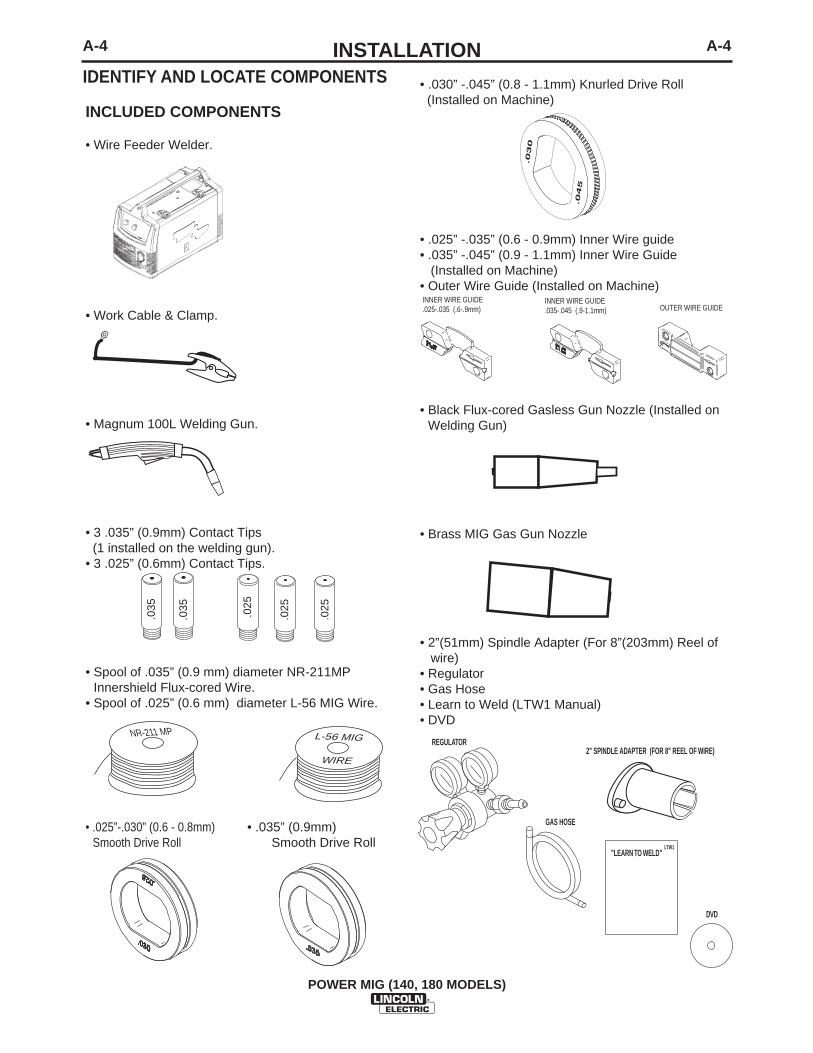
INCLUDED COMPONENTS
• Wire Feeder Welder.
• Work Cable & Clamp.
• Magnum 100L Welding Gun.
• 3 .035” (0.9mm) Contact Tips(1 installed on the welding gun).
• 3 .025” (0.6mm) Contact Tips.
• Spool of .035” (0.9 mm) diameter NR-211MPInnershield Flux-cored Wire.
• Spool of .025” (0.6 mm) diameter L-56 MIG Wire.
• .025”-.030” (0.6 - 0.8mm) • .035” (0.9mm)Smooth Drive Roll Smooth Drive Roll
.025
.025
.025
.035
.035
NR-211 MP
WIRE
L-56 MIG
• .030” -.045” (0.8 - 1.1mm) Knurled Drive Roll (Installed on Machine)
• .025” -.035” (0.6 - 0.9mm) Inner Wire guide• .035” -.045” (0.9 - 1.1mm) Inner Wire Guide
(Installed on Machine)• Outer Wire Guide (Installed on Machine)
• Black Flux-cored Gasless Gun Nozzle (Installed onWelding Gun)
• Brass MIG Gas Gun Nozzle
• 2”(51mm) Spindle Adapter (For 8”(203mm) Reel of wire)
• Regulator• Gas Hose• Learn to Weld (LTW1 Manual)• DVD
OUTER WIRE GUIDEINNER WIRE GUIDE.025-.035 (.6-.9mm)
INNER WIRE GUIDE.035-.045 (.9-1.1mm)
.030
.045
LTW1"LEARN TO WELD"
DVD
GAS HOSE
REGULATOR2" SPINDLE ADAPTER (FOR 8" REEL OF WIRE)
IDENTIFY AND LOCATE COMPONENTS
B-1OPERATIONB-1
POWER MIG (140, 180 MODELS)
COMMON WELDING ABBREVIATIONS
GMAW (MIG)• Gas Metal Arc Welding
FCAW (Innershield or Outershield)• Flux Core Arc Welding
PRODUCT DESCRIPTION (PRODUCTCAPABILITIES)
These small portable wire feed welders are capable ofMIG welding on steel, stainless steel, and aluminum.They are also capable of flux-cored welding on mildsteel.
MIG welding stands for Metal Inert Gas welding andrequires a separate bottle of shielding gas to protectthe weld until it cools. Appropriate shielding gasbased on the type of material you are welding can bepurchased separately from your local welding gas dis-tributor. MIG welding is ideal for welding on thinnerand clean materials when a very clean excellent cos-metic looking weld is required. An example would beautomotive body panels.
Flux-cored Welding does not require separate shield-ing gas to protect the weld since the welding wire hasspecial additives known as flux to protect the welduntil it cools. Flux-cored welding is ideal for mediumto thicker material and if welding on painted or rustysteel. Flux-cored welding is also ideal in outdoorapplications where windy conditions might blow theMIG shielding gas away from the weld. Flux-coredwelding produces a good looking weld but does notproduce an excellent weld appearance as MIG weld-ing does.
Your machine includes the necessary items to weldwith either the MIG or the flux-cored welding processon steel. To weld on stainless steel optional stainlesssteel welding wire can be purchased separately. Thismachine can weld aluminum using .035”(0.9mm)diameter 4043 aluminum welding wire. Since alu-minum welding wire is soft an optional aluminumspool gun is recommended for best results. A weldingProcedure Decal is located inside machine door tohelp provide suggested settings for welding.
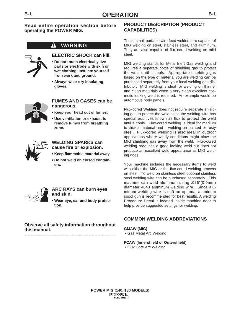
Read entire operation section beforeoperating the POWER MIG.
ELECTRIC SHOCK can kill.• Do not touch electrically live
parts or electrode with skin orwet clothing. Insulate yourselffrom work and ground.
• Always wear dry insulatinggloves.
FUMES AND GASES can bedangerous.• Keep your head out of fumes.
• Use ventilation or exhaust toremove fumes from breathingzone.
WELDING SPARKS cancause fire or explosion.• Keep flammable material away.
• Do not weld on closed contain-ers.
ARC RAYS can burn eyesand skin.• Wear eye, ear and body protec-
tion.
Observe all safety information throughoutthis manual.------------------------------------------------------------
WARNING
B-2OPERATIONB-2
POWER MIG (140, 180 MODELS)
CONTROLS AND SETTINGS
This machine has the following controls:
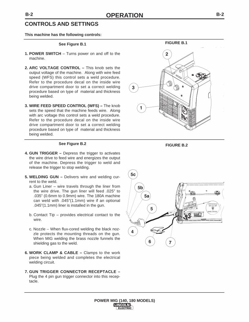
See Figure B.1
1. POWER SWITCH – Turns power on and off to themachine.
2. ARC VOLTAGE CONTROL – This knob sets theoutput voltage of the machine. Along with wire feedspeed (WFS) this control sets a weld procedure.Refer to the procedure decal on the inside wiredrive compartment door to set a correct weldingprocedure based on type of material and thicknessbeing welded.
3. WIRE FEED SPEED CONTROL (WFS) – The knobsets the speed that the machine feeds wire. Alongwith arc voltage this control sets a weld procedure.Refer to the procedure decal on the inside wiredrive compartment door to set a correct weldingprocedure based on type of material and thicknessbeing welded.
See Figure B.2
4. GUN TRIGGER – Depress the trigger to activatesthe wire drive to feed wire and energizes the outputof the machine. Depress the trigger to weld andrelease the trigger to stop welding.
5. WELDING GUN – Delivers wire and welding cur-rent to the weld.a. Gun Liner – wire travels through the liner from
the wire drive. The gun liner will feed .025” to.035” (0.6mm to 0.9mm) wire. The 180A machinecan weld with .045”(1.1mm) wire if an optional.045”(1.1mm) liner is installed in the gun.
b. Contact Tip – provides electrical contact to thewire.
c. Nozzle – When flux-cored welding the black noz-zle protects the mounting threads on the gun.When MIG welding the brass nozzle funnels theshielding gas to the weld.
6. WORK CLAMP & CABLE – Clamps to the workpiece being welded and completes the electricalwelding circuit.
7. GUN TRIGGER CONNECTOR RECEPTACLE –Plug the 4 pin gun trigger connector into this recep-tacle.
1
3
2
FIGURE B.1
FIGURE B.2
.035"(0.9mm) NR-211-MP
WIRE SPOOL
4
5a
5b
5
5c
6 7

B-3OPERATIONB-3
POWER MIG (140, 180 MODELS)
See Figure B.3
8. WELDING GUN CONNECTOR BUSHING &THUMBSCREW – Provides electrical power to thewelding gun. The thumbscrew holds the weldinggun into the connector block. (Front of Machine,Side Door and Wire Drive Cover have beenremoved for clarity of Items 8 and 9).
9. OUTPUT TERMINALS –These connections allowto change the welding polarity of the machinedepending on whether you are MIG welding or flux-cored welding.
See Figure B.4
10. WIRE SPOOL SPINDLE AND BRAKE – Holds a4”(102mm) diameter spool. Use the 2”(51mm)spindle adapter included with the machine to use8”(203mm) diameter spools. The thumbscrewsets the brake friction to prevent the spool fromover rotating when the trigger is released.
See Figure B.5
11. WIRE DRIVE & COMPONENTS – Feeds wirefrom the wire spool through the drive and throughthe welding gun to the weld.
a. Top and Bottom Drive Roll – Drives the wirethrough the drive system. The drive roll has agroove to match the specific wire type and diam-eter. Refer to Table B.1 for available drive rolls.
b. Inner & Outer Wire Guide – Guides the wirebetween the Top and Bottom Drive Roll andthrough the wire drive. The inner guide has agroove to match a particular wire diameter.Refer to Table B.1 for available wire guides.
c. Drive Roll Tension Thumbscrew – Turningclockwise increases the force on the drive rollsand turning counterclockwise decreases theforce.
8
9
FIGURE B.3
2"(51mm) SPINDLE ADAPTER (FOR 8"(20mm) REEL OF WIRE)
( 4"(102mm) REEL OF WIRE)
FIGURE B.4
FIGURE B.5
WIRE SPOOL.035" (0.9mm)
NR-211-MP
INNER WIRE GUIDE REMOVED
LOWER DRIVE ROLL REMOVED
OUTER WIRE GUIDE REMOVED
TOP DRIVE ROLL PRESSURE ARM
TENSION ADJUSTOR DOWN
B-4OPERATIONB-4
POWER MIG (140, 180 MODELS)
TABLE B.1
DRIVE ROLL AND WIRE GUIDES
Wire Diameter &Type
.025”(0.6mm) MIG wire
.030”(0.8mm) MIG wire
.035”(0.9mm) MIG wire
.030”(0.8mm) flux-cored
.035”(0.9mm) flux-cored
.045”(1.1mm) flux-cored
Drive Roll
.025”/.030” (0.6mm/0.8mm)Smooth Drive Roll
.035”(0.9mm) Smooth Drive Roll
.030”/.045” (0.8mm/1.1mm)Knurled Drive Roll
.030”/.045” (0.8mm/1.1mm)Knurled Drive Roll
Inner Wire Guide
.025”-.035”(0.6mm-0.9mm)Steel Wire Guide
.045”(1.1mm) Steel Wire Guide
Inner Wire GuidePart Number
KP2531-1
KP2531-2
Drive Roll PartNumber
KP2529-1
KP2529-2
KP2529-3
KP2529-3
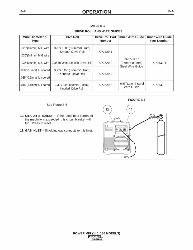
See Figure B.6
12. CIRCUIT BREAKER – If the rated input current ofthe machine is exceeded this circuit breaker willtrip. Press to reset.
13. GAS INLET – Shielding gas connects to this inlet.
12 13
FIGURE B.6
B-5OPERATIONB-5
POWER MIG (140, 180 MODELS)
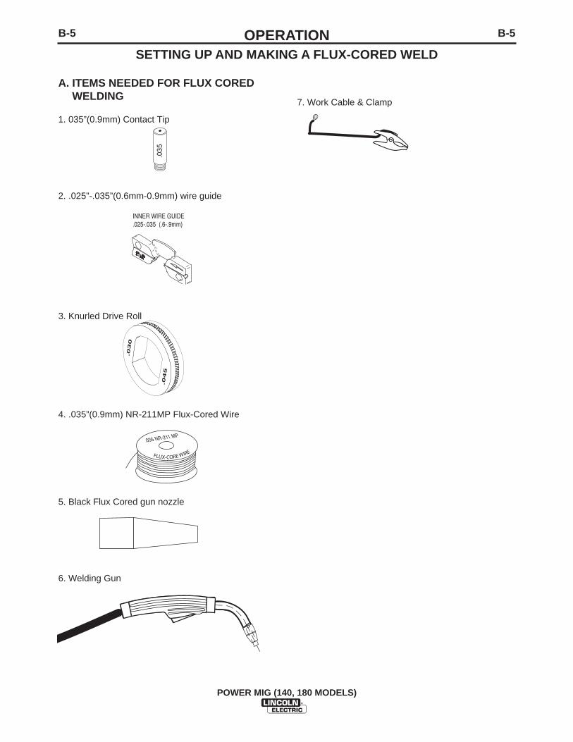
A. ITEMS NEEDED FOR FLUX COREDWELDING
1. 035”(0.9mm) Contact Tip
2. .025”-.035”(0.6mm-0.9mm) wire guide
3. Knurled Drive Roll
4. .035”(0.9mm) NR-211MP Flux-Cored Wire
5. Black Flux Cored gun nozzle
6. Welding Gun
INNER WIRE GUIDE.025-.035 (.6-.9mm)
.035
.035 NR-211 MP
FLUX-CORE WIRE
7. Work Cable & Clamp
.030
.045
SETTING UP AND MAKING A FLUX-CORED WELD

B-6OPERATIONB-6
POWER MIG (140, 180 MODELS)
B. CONNECT LEADS AND CABLES ONTHE MACHINE
(See Figure B.7)1. Open the case side door
2. Slide the connector end of the gun and cablethrough the hole in the machine front and into thegun connector bushing on the wire drive.
3. Make sure the gun connector end is seated fullyinto the wire drive and tighten the thumbscrew tosecure the gun connector.
4. Plug the gun trigger lead connector into the 4 pingun trigger receptacle on the machine front.
5. Wire Drive Polarity. Flux cored welding requiresnegative (-) polarity. Connect the short powercable from the wire drive to the negative (-) outputterminal and tighten the thumbscrew.
6. Work Lead Connection. Slide the lugged end ofthe work cable through the hole in the machinefront and place on the positive (+) output terminaland tighten thumbscrew.
C. LOAD WIRE SPOOL
(See Figure B.8)1. Locate the blue labeled 4"(102mm) diameter
spool of .035”(0.9mm) NR-211MP flux-cored wireand place onto wire spool spindle. Orient thespool so that the wire feeds off the top of thespool.
2. Secure spool in place by tightening the wing nutagainst the against the spacer that holds the wirespool on the spindle.
3. Open the top drive roll pressure arm by rotatingthe tension adjustor arm down and pivoting thedrive roll pressure arm up.
4. Remove the outer wire guide.
4a. Slide gun out of drive slightly.
5. Remove the lower drive roll and inner wire guide.
6. Install the .025”-.035”(0.6mm-0.9mm) inner wire guide.
7. Install the .030”/.045”(0.8mm/1.1mm) knurled lower drive roll.
8. Carefully unwind and straighten the first six inches ofwelding wire from the spool. Do not let the end of thewire go to prevent the wire from unspooling.
GUN AND CABLE
WORK CLAMP
(4 PIN)LEAD CONNECTOR
TERMINAL END (FITS ON STUD INSIDESEE FIGURE BELOW)
SLIDECONNECTOREND HERE
CASE SIDE DOOR
OPEN LATCH DOOR
WORK CLAMP
(4 PIN)TRIGGER RECEPTACLEPLUGGED IN
CONNECTOREND ATTACH
ALL COMPONENTS SHOWN CONNECTED(FRONT AND SIDE DOOR IS REMOVED FOR CLARITY)
SHORT POWERCABLE NEGATIVE "-"OUTPUT TERMINAL
WORK LEAD CONNECTIONPOSITIVE "+"OUTPUT TERMINAL
THUMB SCREW TOTIGHTEN CONNECTOR BUSHING
LOCATE COMPONENTSTO CONNECT TO THEFRONT OF MACHINE
FIGURE B.7
WIRE SPOOL.035" (0.9mm)
NR-211-MP
INNER WIRE GUIDE REMOVED
LOWER DRIVE ROLL REMOVED
OUTER WIRE GUIDE REMOVED
TOP DRIVE ROLL PRESSURE ARM
TENSION ADJUSTOR DOWN
FIGURE B.8
B-7OPERATIONB-7
POWER MIG (140, 180 MODELS)
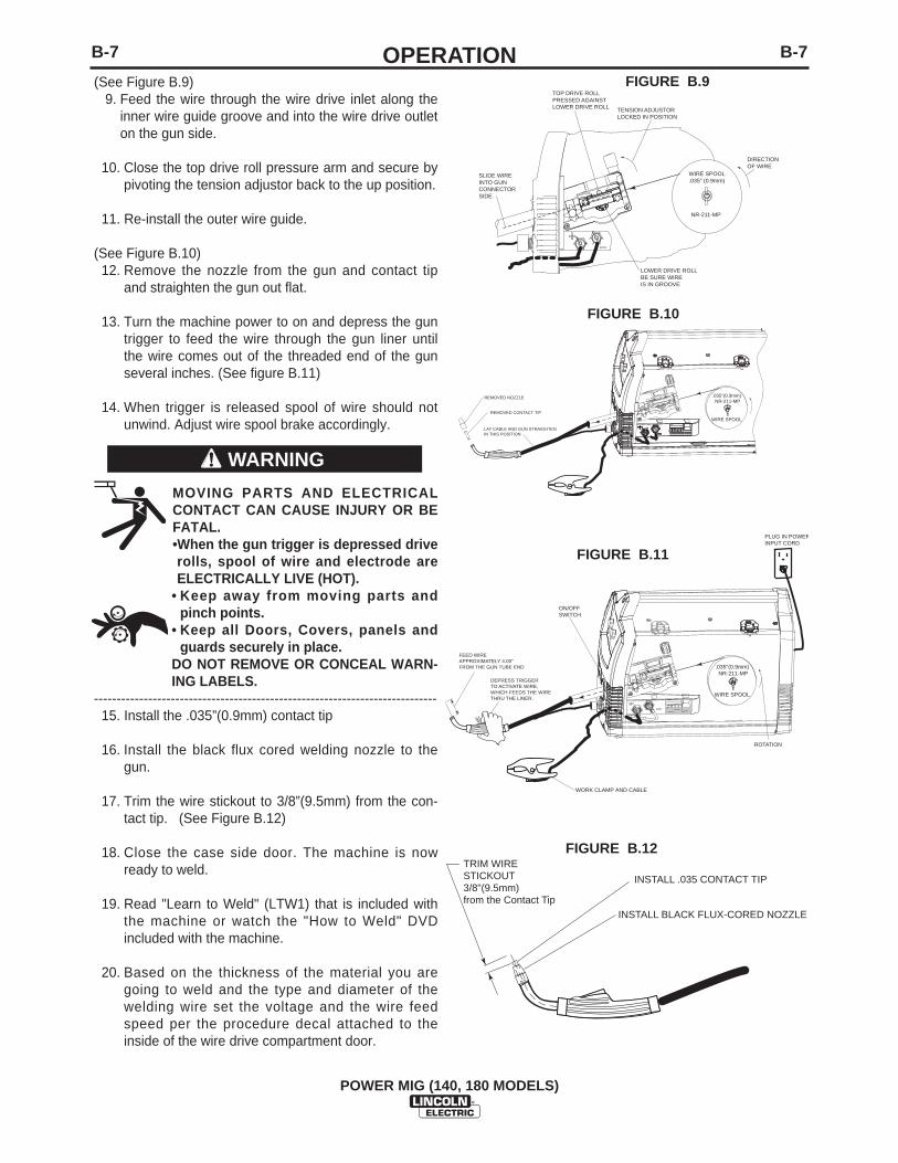
(See Figure B.9)9. Feed the wire through the wire drive inlet along the
inner wire guide groove and into the wire drive outleton the gun side.
10. Close the top drive roll pressure arm and secure bypivoting the tension adjustor back to the up position.
11. Re-install the outer wire guide.
(See Figure B.10)12. Remove the nozzle from the gun and contact tip
and straighten the gun out flat.
13. Turn the machine power to on and depress the guntrigger to feed the wire through the gun liner untilthe wire comes out of the threaded end of the gunseveral inches. (See figure B.11)
14. When trigger is released spool of wire should notunwind. Adjust wire spool brake accordingly.
MOVING PARTS AND ELECTRICALCONTACT CAN CAUSE INJURY OR BEFATAL.•When the gun trigger is depressed driverolls, spool of wire and electrode areELECTRICALLY LIVE (HOT).
• Keep away from moving parts andpinch points.
• Keep all Doors, Covers, panels andguards securely in place.
DO NOT REMOVE OR CONCEAL WARN-ING LABELS.
----------------------------------------------------------------------------15. Install the .035”(0.9mm) contact tip
16. Install the black flux cored welding nozzle to thegun.
17. Trim the wire stickout to 3/8”(9.5mm) from the con-tact tip. (See Figure B.12)
18. Close the case side door. The machine is nowready to weld.
19. Read "Learn to Weld" (LTW1) that is included withthe machine or watch the "How to Weld" DVDincluded with the machine.
20. Based on the thickness of the material you aregoing to weld and the type and diameter of thewelding wire set the voltage and the wire feedspeed per the procedure decal attached to theinside of the wire drive compartment door.
.035"(0.9mm) NR-211-MP
WIRE SPOOL
REMOVED NOZZLE
REMOVED CONTACT TIP
LAY CABLE AND GUN STRAIGHTENIN THIS POSITION
.035"(0.9mm) NR-211-MP
WIRE SPOOL
DEPRESS TRIGGER TO ACTIVATE WIRE,WHICH FEEDS THE WIRETHRU THE LINER.
FEED WIREAPPROXIMATELY 4.00"FROM THE GUN TUBE END
ROTATION
PLUG IN POWERINPUT CORD
ON/OFFSWITCH
WORK CLAMP AND CABLE
TENSION ADJUSTORLOCKED IN POSITION
LOWER DRIVE ROLLBE SURE WIREIS IN GROOVE
WIRE SPOOL.035" (0.9mm)
SLIDE WIRE INTO GUN CONNECTORSIDE
TOP DRIVE ROLL PRESSED AGAINSTLOWER DRIVE ROLL
DIRECTIONOF WIRE
NR-211-MP
FIGURE B.10
FIGURE B.11
WARNING
INSTALL .035 CONTACT TIP
INSTALL BLACK FLUX-CORED NOZZLE
TRIM WIRE STICKOUT3/8"(9.5mm)from the Contact Tip
FIGURE B.9
FIGURE B.12
B-8OPERATIONB-8
POWER MIG (140, 180 MODELS)
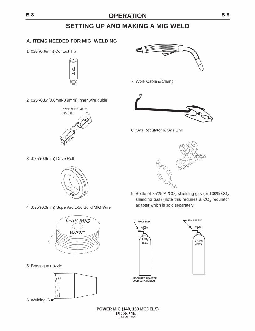
A. ITEMS NEEDED FOR MIG WELDING
1. 025”(0.6mm) Contact Tip
2. 025”-035”(0.6mm-0.9mm) Inner wire guide
3. .025”(0.6mm) Drive Roll
4. .025”(0.6mm) SuperArc L-56 Solid MIG Wire
5. Brass gun nozzle
6. Welding Gun
.025
WIRE
L-56 MIG
7. Work Cable & Clamp
8. Gas Regulator & Gas Line
9. Bottle of 75/25 Ar/CO2 shielding gas (or 100% CO2
shielding gas) (note this requires a CO2 regulatoradapter which is sold separately.
INNER WIRE GUIDE.025-.035
.025-.035
75/25
FEMALE END
MIXES
MALE END
CO100%
2
(REQUIRES ADAPTER�SOLD SEPARATELY)
SETTING UP AND MAKING A MIG WELD
B-9OPERATIONB-9
POWER MIG (140, 180 MODELS)
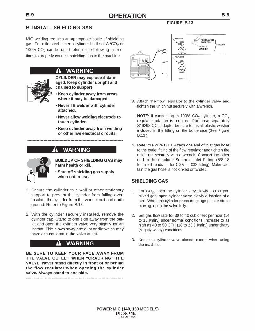
B. INSTALL SHIELDING GAS
MIG welding requires an appropriate bottle of shieldinggas. For mild steel either a cylinder bottle of Ar/CO2 or100% CO2 can be used refer to the following instruc-
tions to properly connect shielding gas to the machine.
CYLINDER may explode if dam-aged. Keep cylinder upright andchained to support
• Keep cylinder away from areaswhere it may be damaged.
• Never lift welder with cylinderattached.
• Never allow welding electrode totouch cylinder.
• Keep cylinder away from weldingor other live electrical circuits.
-----------------------------------------------------------------------
WARNING 75/25
FEMALE END
MALE END
CO
S19298
REGULATORADAPTER
PLASTIC WASHER
MIXES
100%2
3. Attach the flow regulator to the cylinder valve andtighten the union nut securely with a wrench.
NOTE: If connecting to 100% CO2 cylinder, a CO2regulator adapter is required. Purchase separatelyS19298 CO2 adapter be sure to install plastic washerincluded in the fitting on the bottle side.(See FigureB.13 )
4. Refer to Figure B.13. Attach one end of inlet gas hoseto the outlet fitting of the flow regulator and tighten theunion nut securely with a wrench. Connect the otherend to the machine Solenoid Inlet Fitting (5/8-18female threads — for CGA — 032 fitting). Make cer-tain the gas hose is not kinked or twisted.
FIGURE B.13
BUILDUP OF SHIELDING GAS mayharm health or kill.
• Shut off shielding gas supplywhen not in use.
1. Secure the cylinder to a wall or other stationarysupport to prevent the cylinder from falling over.Insulate the cylinder from the work circuit and earthground. Refer to Figure B.13.
2. With the cylinder securely installed, remove thecylinder cap. Stand to one side away from the out-let and open the cylinder valve very slightly for aninstant. This blows away any dust or dirt which mayhave accumulated in the valve outlet.
BE SURE TO KEEP YOUR FACE AWAY FROMTHE VALVE OUTLET WHEN “CRACKING” THEVALVE. Never stand directly in front of or behindthe flow regulator when opening the cylindervalve. Always stand to one side.------------------------------------------------------------------------
WARNING
WARNING
SHIELDING GAS
1. For CO2, open the cylinder very slowly. For argon-mixed gas, open cylinder valve slowly a fraction of aturn. When the cylinder pressure gauge pointer stopsmoving, open the valve fully.
2. Set gas flow rate for 30 to 40 cubic feet per hour (14to 18 I/min.) under normal conditions, increase to ashigh as 40 to 50 CFH (18 to 23.5 I/min.) under drafty(slightly windy) conditions.
3. Keep the cylinder valve closed, except when usingthe machine.

B-10OPERATIONB-10
POWER MIG (140, 180 MODELS)
C. CONNECT LEADS AND CABLES ONTHE MACHINE
(See Figure B.14)1. Open the case side door.
2. Slide the connector end of the gun and cablethrough the hole of the machine front and into thegun connector bushing on the wire drive.
3. Make sure the gun connector end is seated fullyinto the wire drive and tighten the thumbscrew tosecure the gun.
4. Plug the gun trigger lead connector into the 4 pingun trigger receptacle on the machine front.
5. Wire Drive Polarity. MIG welding requires Positive(+) polarity. Connect the short power cable fromthe wire drive to the positive (+) output terminal andtighten the thumbscrew.
6. Work Lead Connection. Slide the lugged end of thework cable through the hole in the machine frontand place on the negative (-) output terminal andtighten thumbscrew.
D. LOAD WIRE SPOOL
(See Figure B.15)1. Locate the green labeled 4"(102mm) diameter
spool of .025”(0.6mm) L-56 solid MIG wire andplace onto wire spool spindle. Orient the spool sothat the wire feeds off the top of the spool.
2. Secure spool in place by tightening the wing nutagainst the against the spacer that holds the wirespool on the spindle.
3. Open the top drive roll pressure arm by rotating thetension adjustor arm down and pivoting the idle rollpressure arm up.
4. Remove the outer wire guide.
4a. Slide gun out of drive slightly.
5. Remove the lower drive roll and inner wire guide.
6. Install the .025”-.035”(0.6mm-0.9mm) inner wire guide.
7. Install the .025”(0.6mm) smooth grooved lower drive roll.
8. Carefully unwind and straighten the first six inchesof welding wire from the spool. Do not let the endof the wire go to prevent the wire from unspooling.
GUN AND CABLE
WORK CLAMP
(4 PIN)LEAD CONNECTOR
TERMINAL END (FITS ON STUD INSIDESEE FIGURE BELOW)
SLIDECONNECTOREND HERE
CASE SIDE DOOR
OPEN LATCH DOOR
WORK CLAMP
(4 PIN)TRIGGER RECEPTACLEPLUGGED IN
CONNECTOREND ATTACH
ALL COMPONENTS SHOWN CONNECTED(FRONT AND SIDE DOOR IS REMOVED FOR CLARITY)
SHORT POWERCABLE POSITIVE "+"OUTPUT TERMINAL
WORK LEAD CONNECTIONNEGATIVE "-"OUTPUT TERMINAL
THUMB SCREW TOTIGHTEN CONNECTOR BUSHING
LOCATE COMPONENTSTO CONNECT TO THEFRONT OF MACHINE
FIGURE B.15
FIGURE B.14
WIRE SPOOL.025" (0.6mm)
INNER WIRE GUIDE REMOVED
LOWER DRIVE ROLL REMOVED
OUTER WIRE GUIDE REMOVED
TOP DRIVE ROLL PRESSURE ARM
TENSION ADJUSTOR DOWN
L-56 SOLID MIG
B-11OPERATIONB-11
POWER MIG (140, 180 MODELS)
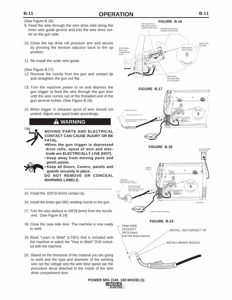
(See Figure B.16)9. Feed the wire through the wire drive inlet along the
inner wire guide groove and into the wire drive out-let on the gun side.
10. Close the top drive roll pressure arm and secureby pivoting the tension adjustor back to the upposition.
11. Re-install the outer wire guide.
(See Figure B.17)12. Remove the nozzle from the gun and contact tip
and straighten the gun out flat.
13. Turn the machine power to on and depress thegun trigger to feed the wire through the gun lineruntil the wire comes out of the threaded end of thegun several inches. (See Figure B.18)
14. When trigger is released spool of wire should notunwind. Adjust wire spool brake accordingly.
MOVING PARTS AND ELECTRICALCONTACT CAN CAUSE INJURY OR BEFATAL.•When the gun trigger is depresseddrive rolls, spool of wire and elec-trode are ELECTRICALLY LIVE (HOT).
• Keep away from moving parts andpinch points.
• Keep all Doors, Covers, panels andguards securely in place.
DO NOT REMOVE OR CONCEALWARNING LABELS.
-----------------------------------------------------------------------15. Install the .025”(0.6mm) contact tip.
16. Install the brass gas MIG welding nozzle to the gun.
17. Trim the wire stickout to 3/8”(9.5mm) from the nozzle end. (See Figure B.19)
18. Close the case side door. The machine is now readyto weld.
19. Read "Learn to Weld" (LTW1) that is included withthe machine or watch the "How to Weld" DVD includ-ed with the machine.
20. Based on the thickness of the material you are goingto weld and the type and diameter of the weldingwire set the voltage and the wire feed speed per theprocedure decal attached to the inside of the wiredrive compartment door.
TENSION ADJUSTORLOCKED IN POSITION
DRIVE ROLLBE SURE WIREIS IN GROOVE
WIRE SPOOL.025" (0.6mm)
SLIDE WIRE INTO GUN CONNECTORSIDE
TOP IDLER ROLL PRESSED AGAINSTLOWER DRIVE ROLL
DIRECTIONOF WIRE
L-56 SOLID MIG
REMOVED NOZZLE
REMOVED CONTACT TIP
LAY CABLE AND GUN STRAIGHTENIN THIS POSITION
WIRE SPOOL.025" (0.6mm)
L-56 SOLID MIG
DEPRESS TRIGGERTO ACTIVATE WIRE,WHICH FEEDS THE WIRETHRU THE LINER.
FEED WIREAPPROXIMATELY 4.00"FROM THE GUN TUBE END
ROTATION
PLUG IN POWERINPUT CORD
ON/OFFSWITCH
WORK CLAMP AND CABLE
WIRE SPOOL.025" (0.6mm)
L-56 SOLID MIG
INSTALL .025 CONTACT TIP
INSTALL BRASS NOZZLE
TRIM WIRE STICKOUT3/8"(9.5mm)from the Brass Nozzle
FIGURE B.17
FIGURE B.18
FIGURE B.19
FIGURE B.16
WARNING
B-12OPERATIONB-12
1. Follow the MIG welding steps in the previous sec-tion.
2. Connect a bottle of 100% Argon shielding Gas perprevious section.
3. Disconnect Magnum 100L Gun.
4. Install optional K2532-1 Magnum 100SG spool gunper instructions included with gun.
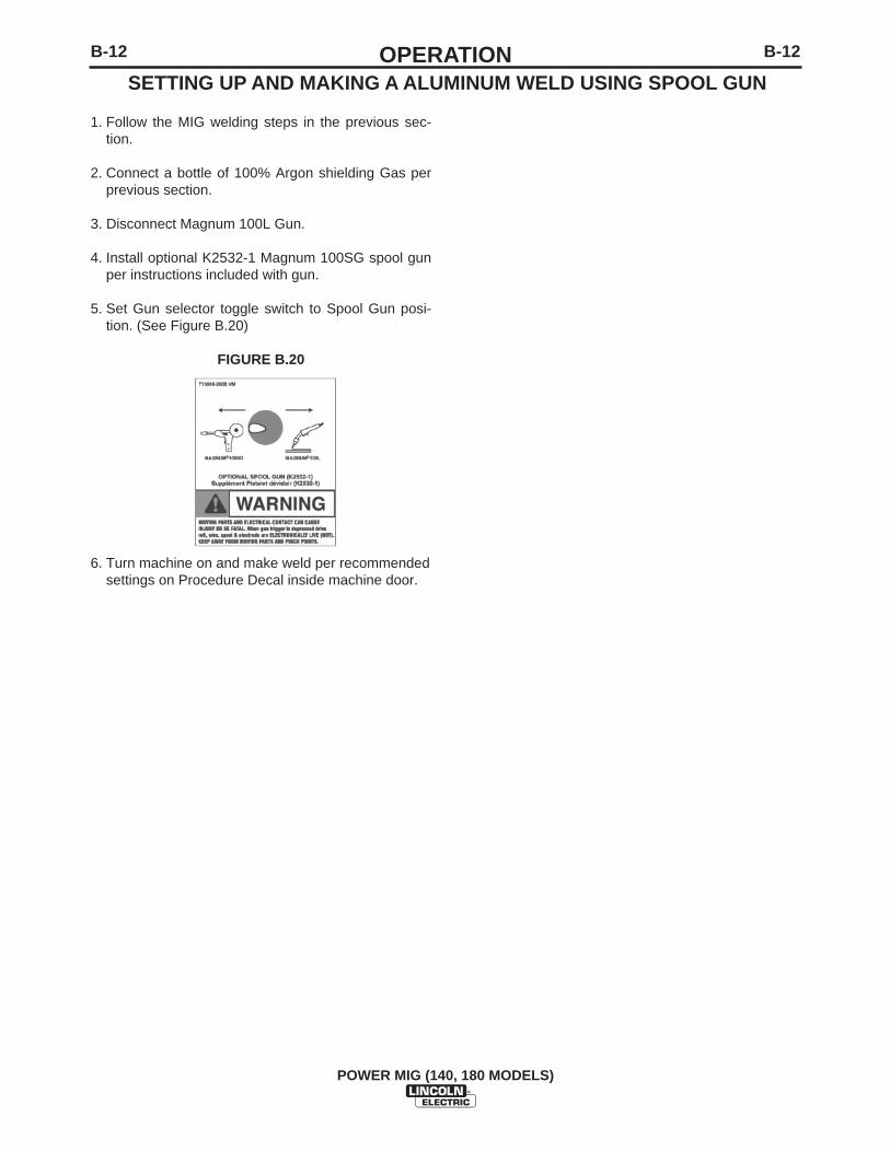
5. Set Gun selector toggle switch to Spool Gun posi-tion. (See Figure B.20)
FIGURE B.20
6. Turn machine on and make weld per recommendedsettings on Procedure Decal inside machine door.
POWER MIG (140, 180 MODELS)
SETTING UP AND MAKING A ALUMINUM WELD USING SPOOL GUN
C-1ACCESSORIESC-1
POWER MIG (140, 180 MODELS)
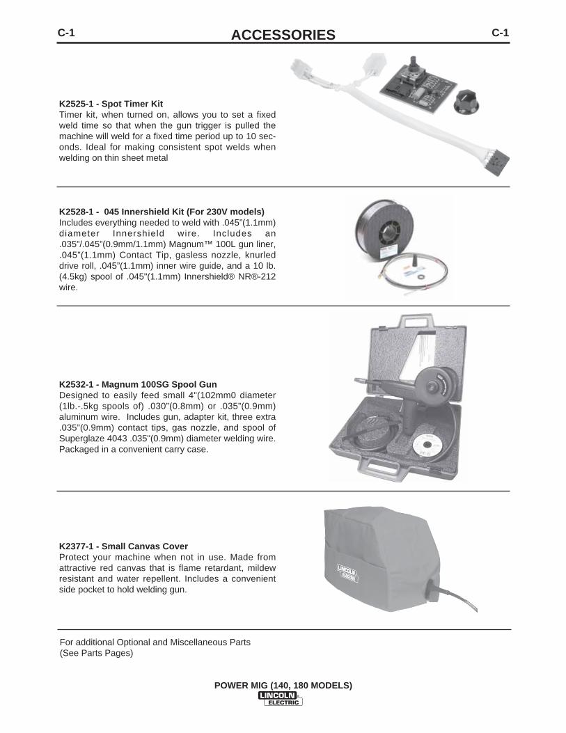
K2525-1 - Spot Timer Kit Timer kit, when turned on, allows you to set a fixedweld time so that when the gun trigger is pulled themachine will weld for a fixed time period up to 10 sec-onds. Ideal for making consistent spot welds whenwelding on thin sheet metal
K2528-1 - 045 Innershield Kit (For 230V models) Includes everything needed to weld with .045”(1.1mm)diameter Innershield wire. Includes an.035”/.045”(0.9mm/1.1mm) Magnum™ 100L gun liner,.045”(1.1mm) Contact Tip, gasless nozzle, knurleddrive roll, .045”(1.1mm) inner wire guide, and a 10 lb.(4.5kg) spool of .045"(1.1mm) Innershield® NR®-212wire.
K2532-1 - Magnum 100SG Spool Gun Designed to easily feed small 4"(102mm0 diameter(1lb.-.5kg spools of) .030”(0.8mm) or .035”(0.9mm)aluminum wire. Includes gun, adapter kit, three extra.035”(0.9mm) contact tips, gas nozzle, and spool ofSuperglaze 4043 .035"(0.9mm) diameter welding wire.Packaged in a convenient carry case.
K2377-1 - Small Canvas Cover Protect your machine when not in use. Made fromattractive red canvas that is flame retardant, mildewresistant and water repellent. Includes a convenientside pocket to hold welding gun.
For additional Optional and Miscellaneous Parts(See Parts Pages)
C-2ACCESSORIESC-2
POWER MIG (140, 180 MODELS)
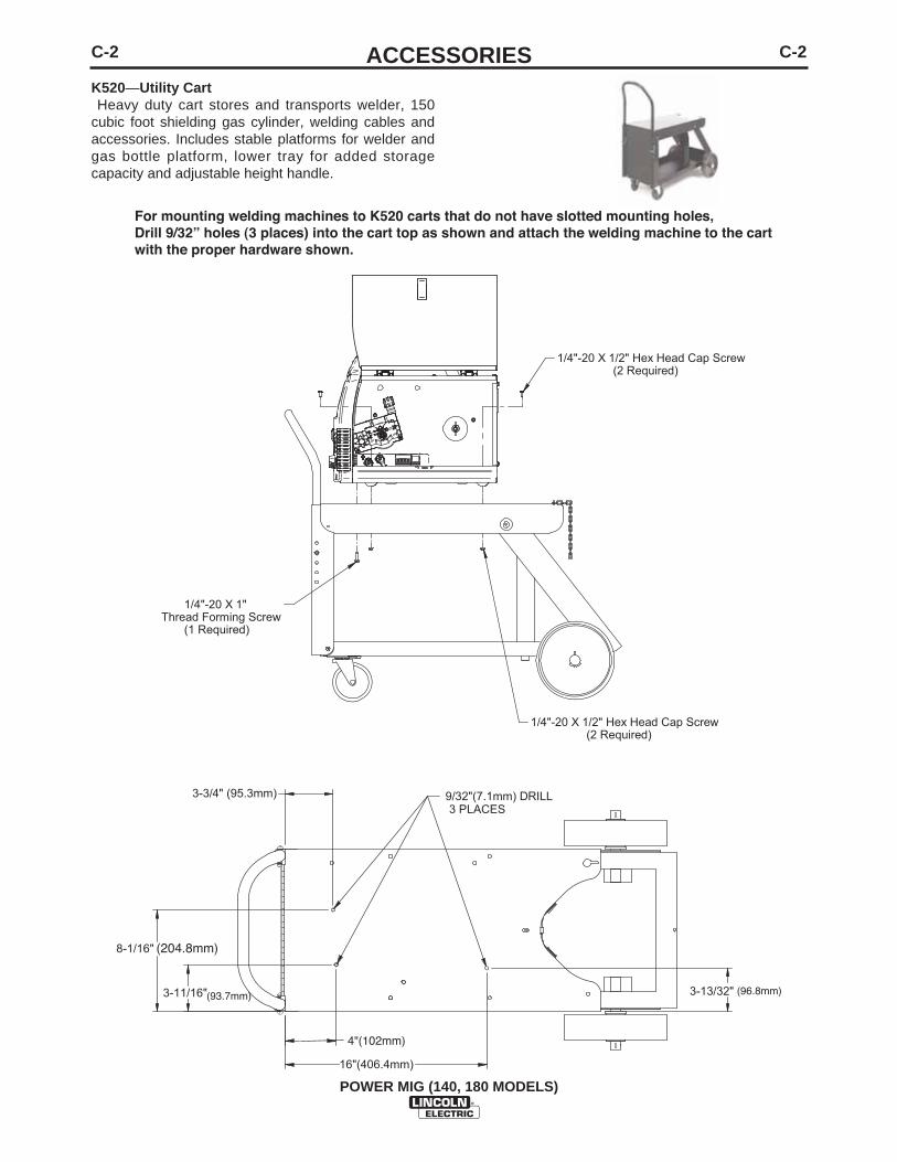
3-3/4" (95.3mm)
4"(102mm)
16"(406.4mm)
3-11/16"
8-1/16"
3-13/32"
9/32"(7.1mm) DRILL 3 PLACES
1/4"-20 X 1/2" Hex Head Cap Screw (2 Required)
1/4"-20 X 1" Thread Forming Screw (1 Required)
1/4"-20 X 1/2" Hex Head Cap Screw (2 Required)
For mounting welding machines to K520 carts that do not have slotted mounting holes,Drill 9/32” holes (3 places) into the cart top as shown and attach the welding machine to the cartwith the proper hardware shown.
(204.8mm)
(93.7mm) (96.8mm)
K520—Utility CartHeavy duty cart stores and transports welder, 150
cubic foot shielding gas cylinder, welding cables andaccessories. Includes stable platforms for welder andgas bottle platform, lower tray for added storagecapacity and adjustable height handle.

C-3ACCESSORIESC-3
POWER MIG (140, 180 MODELS)
2-15/16"(74.6mm)3-3/16"(81mm)
7-9/16"(192.1mm)
1-1/2"(38.1mm)
13-1/2"(342.9mm)
1-1/4"(31.8mm)
9/32"(7.1mm) DRILL 3 PLACES
1/4"-20 Flange Nut (2 Required)
1/4"-20 X 1" Thread Forming Screw (1 Required)
1/4"-20 X 1/2" Hex Head Cap Screw (2 Required)
For mounting welding machines to K2275 carts that do not have slotted mounting holes,Drill 9/32” holes (3 places) into the cart top as shown and attach the welding machine to the cartwith the proper hardware shown.
K2275-1 - Welding CartLightweight cart stores and transports welder, 80cubic foot shielding gas cylinder, welding cables andaccessories. Includes an angled top shelf for easyaccess to controls, lower tray for added storagecapacity, a sturdy fixed handle and convenient cablewrap hanger.
D-1MAINTENANCED-1
POWER MIG (140, 180 MODELS)
MAINTENANCE
SAFETY PRECAUTIONS
ELECTRIC SHOCK can kill.
• Disconnect input power by removingplug from receptacle before workinginside POWER MIG (140, 180 MODELS).Use only grounded receptacle. Do nottouch electrically “hot” parts insidePOWER MIG (140, 180 MODELS).
• Have qualified personnel do the mainte-nance and trouble shooting work.
---------------------------------------------------------------------------------
ROUTINE MAINTENANCE
POWER SOURCE COMPARTMENTNo user serviceable parts inside! Do not attempt to performservice in the power source (fixed) side of the POWER MIG(140, 180 MODELS). Take the unit to an authorized LincolnService Center if you experience problems. NO maintenanceis required.
In extremely dusty locations, dirt may clog the air passagescausing the welder to run hot with premature tripping of ther-mal protection. If so, blow dirt out of the welder with low pres-sure air at regular intervals to eliminate excessive dirt and dustbuild-up on internal parts.
WIRE FEED COMPARTMENT
1. When necessary, vacuum accumulated dirt from gearboxand wire feed section.
2. Occasionally inspect the wire guides and keep groovesclean.
3. Motor and gearbox have lifetime lubrication and require nomaintenance.
FAN MOTOR
Has lifetime lubrication — requires no maintenance.
WIRE REEL SPINDLE
Requires no maintenance. Do not lubricate shaft.
WARNING
D-2MAINTENANCED-2
POWER MIG (140, 180 MODELS)
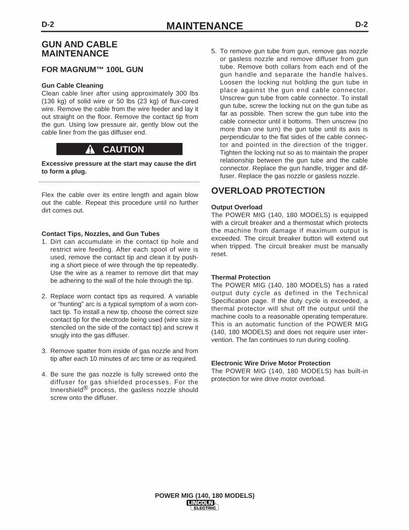
GUN AND CABLE MAINTENANCE
FOR MAGNUM™ 100L GUN
Gun Cable CleaningClean cable liner after using approximately 300 lbs(136 kg) of solid wire or 50 lbs (23 kg) of flux-coredwire. Remove the cable from the wire feeder and lay itout straight on the floor. Remove the contact tip fromthe gun. Using low pressure air, gently blow out thecable liner from the gas diffuser end.
Excessive pressure at the start may cause the dirtto form a plug.
Flex the cable over its entire length and again blowout the cable. Repeat this procedure until no furtherdirt comes out.
Contact Tips, Nozzles, and Gun Tubes1. Dirt can accumulate in the contact tip hole and
restrict wire feeding. After each spool of wire isused, remove the contact tip and clean it by push-ing a short piece of wire through the tip repeatedly.Use the wire as a reamer to remove dirt that maybe adhering to the wall of the hole through the tip.
2. Replace worn contact tips as required. A variableor “hunting” arc is a typical symptom of a worn con-tact tip. To install a new tip, choose the correct sizecontact tip for the electrode being used (wire size isstenciled on the side of the contact tip) and screw itsnugly into the gas diffuser.
3. Remove spatter from inside of gas nozzle and fromtip after each 10 minutes of arc time or as required.
4. Be sure the gas nozzle is fully screwed onto thediffuser for gas shielded processes. For theInnershield® process, the gasless nozzle shouldscrew onto the diffuser.
5. To remove gun tube from gun, remove gas nozzleor gasless nozzle and remove diffuser from guntube. Remove both collars from each end of thegun handle and separate the handle halves.Loosen the locking nut holding the gun tube inplace against the gun end cable connector.Unscrew gun tube from cable connector. To installgun tube, screw the locking nut on the gun tube asfar as possible. Then screw the gun tube into thecable connector until it bottoms. Then unscrew (nomore than one turn) the gun tube until its axis isperpendicular to the flat sides of the cable connec-tor and pointed in the direction of the trigger.Tighten the locking nut so as to maintain the properrelationship between the gun tube and the cableconnector. Replace the gun handle, trigger and dif-fuser. Replace the gas nozzle or gasless nozzle.
OVERLOAD PROTECTION
Output OverloadThe POWER MIG (140, 180 MODELS) is equippedwith a circuit breaker and a thermostat which protectsthe machine from damage if maximum output isexceeded. The circuit breaker button will extend outwhen tripped. The circuit breaker must be manuallyreset.
Thermal ProtectionThe POWER MIG (140, 180 MODELS) has a ratedoutput duty cycle as defined in the TechnicalSpecification page. If the duty cycle is exceeded, athermal protector will shut off the output until themachine cools to a reasonable operating temperature.This is an automatic function of the POWER MIG(140, 180 MODELS) and does not require user inter-vention. The fan continues to run during cooling.
Electronic Wire Drive Motor ProtectionThe POWER MIG (140, 180 MODELS) has built-inprotection for wire drive motor overload.
CAUTION
D-3MAINTENANCED-3
POWER MIG (140, 180 MODELS)
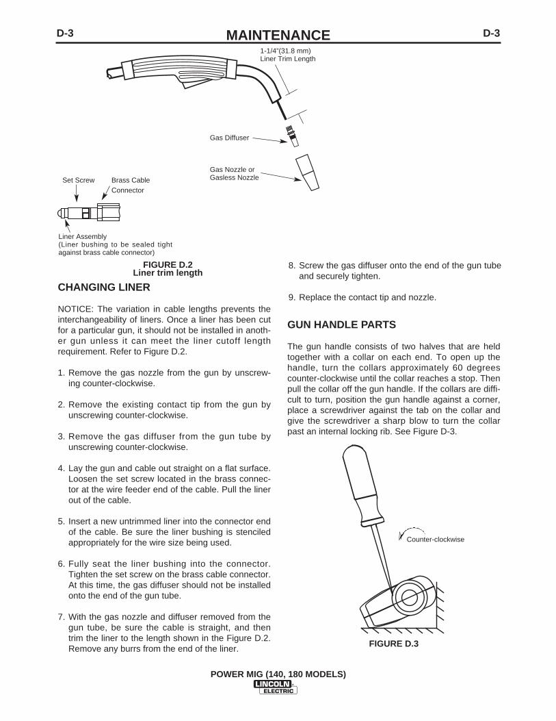
GUN HANDLE PARTS
The gun handle consists of two halves that are heldtogether with a collar on each end. To open up thehandle, turn the collars approximately 60 degreescounter-clockwise until the collar reaches a stop. Thenpull the collar off the gun handle. If the collars are diffi-cult to turn, position the gun handle against a corner,place a screwdriver against the tab on the collar andgive the screwdriver a sharp blow to turn the collarpast an internal locking rib. See Figure D-3.
FIGURE D.3
➣
Counter-clockwise
8. Screw the gas diffuser onto the end of the gun tubeand securely tighten.
9. Replace the contact tip and nozzle.
1-1/4”(31.8 mm)Liner Trim Length
Gas Diffuser
Gas Nozzle orGasless NozzleSet Screw Brass Cable
Connector
Liner Assembly (Liner bushing to be sealed tightagainst brass cable connector)
FIGURE D.2Liner trim length
CHANGING LINER
NOTICE: The variation in cable lengths prevents theinterchangeability of liners. Once a liner has been cutfor a particular gun, it should not be installed in anoth-er gun unless it can meet the liner cutoff lengthrequirement. Refer to Figure D.2.
1. Remove the gas nozzle from the gun by unscrew-ing counter-clockwise.
2. Remove the existing contact tip from the gun byunscrewing counter-clockwise.
3. Remove the gas diffuser from the gun tube byunscrewing counter-clockwise.
4. Lay the gun and cable out straight on a flat surface.Loosen the set screw located in the brass connec-tor at the wire feeder end of the cable. Pull the linerout of the cable.
5. Insert a new untrimmed liner into the connector endof the cable. Be sure the liner bushing is stenciledappropriately for the wire size being used.
6. Fully seat the liner bushing into the connector.Tighten the set screw on the brass cable connector.At this time, the gas diffuser should not be installedonto the end of the gun tube.
7. With the gas nozzle and diffuser removed from thegun tube, be sure the cable is straight, and thentrim the liner to the length shown in the Figure D.2.Remove any burrs from the end of the liner.
E-1TROUBLESHOOTINGE-1
POWER MIG (140, 180 MODELS)
If for any reason you do not understand the test procedures or are unable to perform the tests/repairs safely, contact yourLocal Lincoln Authorized Field Service Facility for technical troubleshooting assistance before you proceed.
CAUTION
This Troubleshooting Guide is provided to help youlocate and repair possible machine malfunctions.Simply follow the three-step procedure listed below.
Step 1. LOCATE PROBLEM (SYMPTOM).Look under the column labeled “PROBLEM (SYMP-TOMS)”. This column describes possible symptomsthat the machine may exhibit. Find the listing thatbest describes the symptom that the machine isexhibiting.
Step 2. POSSIBLE CAUSE.The second column labeled “POSSIBLE CAUSE” liststhe obvious external possibilities that may contributeto the machine symptom.
Step 3. RECOMMENDED COURSE OF ACTIONThis column provides a course of action for thePossible Cause, generally it states to contact yourlocal Lincoln Authorized Field Service Facility.
If you do not understand or are unable to perform theRecommended Course of Action safely, contact yourlocal Lincoln Authorized Field Service Facility.
HOW TO USE TROUBLESHOOTING GUIDE
Service and Repair should only be performed by Lincoln Electric Factory Trained Personnel.Unauthorized repairs performed on this equipment may result in danger to the technician andmachine operator and will invalidate your factory warranty. For your safety and to avoid ElectricalShock, please observe all safety notes and precautions detailed throughout this manual.
__________________________________________________________________________
WARNING
E-2TROUBLESHOOTINGE-2
POWER MIG (140, 180 MODELS)
Observe all Safety Guidelines detailed throughout this manual
If for any reason you do not understand the test procedures or are unable to perform the tests/repairs safely, contact yourLocal Lincoln Authorized Field Service Facility for technical troubleshooting assistance before you proceed.
CAUTION
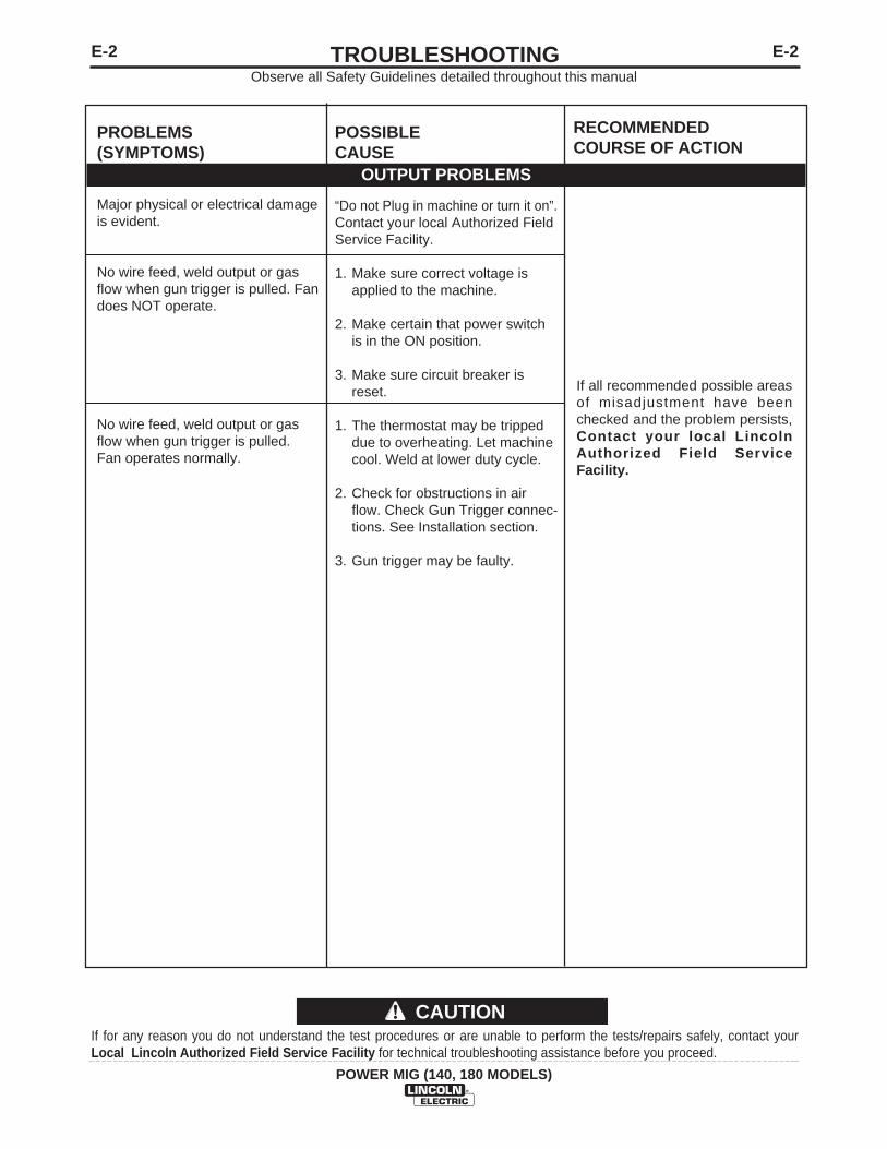
PROBLEMS(SYMPTOMS)
Major physical or electrical damageis evident.
No wire feed, weld output or gasflow when gun trigger is pulled. Fandoes NOT operate.
No wire feed, weld output or gasflow when gun trigger is pulled.Fan operates normally.
POSSIBLE CAUSE
“Do not Plug in machine or turn it on”.Contact your local Authorized FieldService Facility.
1. Make sure correct voltage isapplied to the machine.
2. Make certain that power switchis in the ON position.
3. Make sure circuit breaker isreset.
1. The thermostat may be trippeddue to overheating. Let machinecool. Weld at lower duty cycle.
2. Check for obstructions in airflow. Check Gun Trigger connec-tions. See Installation section.
3. Gun trigger may be faulty.
RECOMMENDEDCOURSE OF ACTION
If all recommended possible areasof misadjustment have beenchecked and the problem persists,Contact your local LincolnAuthorized Field ServiceFacility.
OUTPUT PROBLEMS
E-3TROUBLESHOOTINGE-3
POWER MIG (140, 180 MODELS)
Observe all Safety Guidelines detailed throughout this manual
If for any reason you do not understand the test procedures or are unable to perform the tests/repairs safely, contact yourLocal Lincoln Authorized Field Service Facility for technical troubleshooting assistance before you proceed.
CAUTION
PROBLEMS(SYMPTOMS)
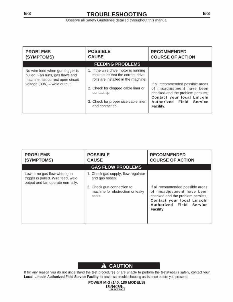
No wire feed when gun trigger ispulled. Fan runs, gas flows andmachine has correct open circuitvoltage (33V) – weld output.
POSSIBLECAUSE
1. If the wire drive motor is runningmake sure that the correct driverolls are installed in the machine.
2. Check for clogged cable liner orcontact tip.
3. Check for proper size cable linerand contact tip.
RECOMMENDEDCOURSE OF ACTION
If all recommended possible areasof misadjustment have beenchecked and the problem persists,Contact your local LincolnAuthorized Field ServiceFacility.
FEEDING PROBLEMS
PROBLEMS(SYMPTOMS)
Low or no gas flow when guntrigger is pulled. Wire feed, weldoutput and fan operate normally.
POSSIBLECAUSE
1. Check gas supply, flow regulatorand gas hoses.
2. Check gun connection tomachine for obstruction or leakyseals.
RECOMMENDEDCOURSE OF ACTION
If all recommended possible areasof misadjustment have beenchecked and the problem persists,Contact your local LincolnAuthorized Field ServiceFacility.
GAS FLOW PROBLEMS
E-4TROUBLESHOOTINGE-4
POWER MIG (140, 180 MODELS)
Observe all Safety Guidelines detailed throughout this manual
If for any reason you do not understand the test procedures or are unable to perform the tests/repairs safely, contact yourLocal Lincoln Authorized Field Service Facility for technical troubleshooting assistance before you proceed.
CAUTION
PROBLEMS(SYMPTOMS)
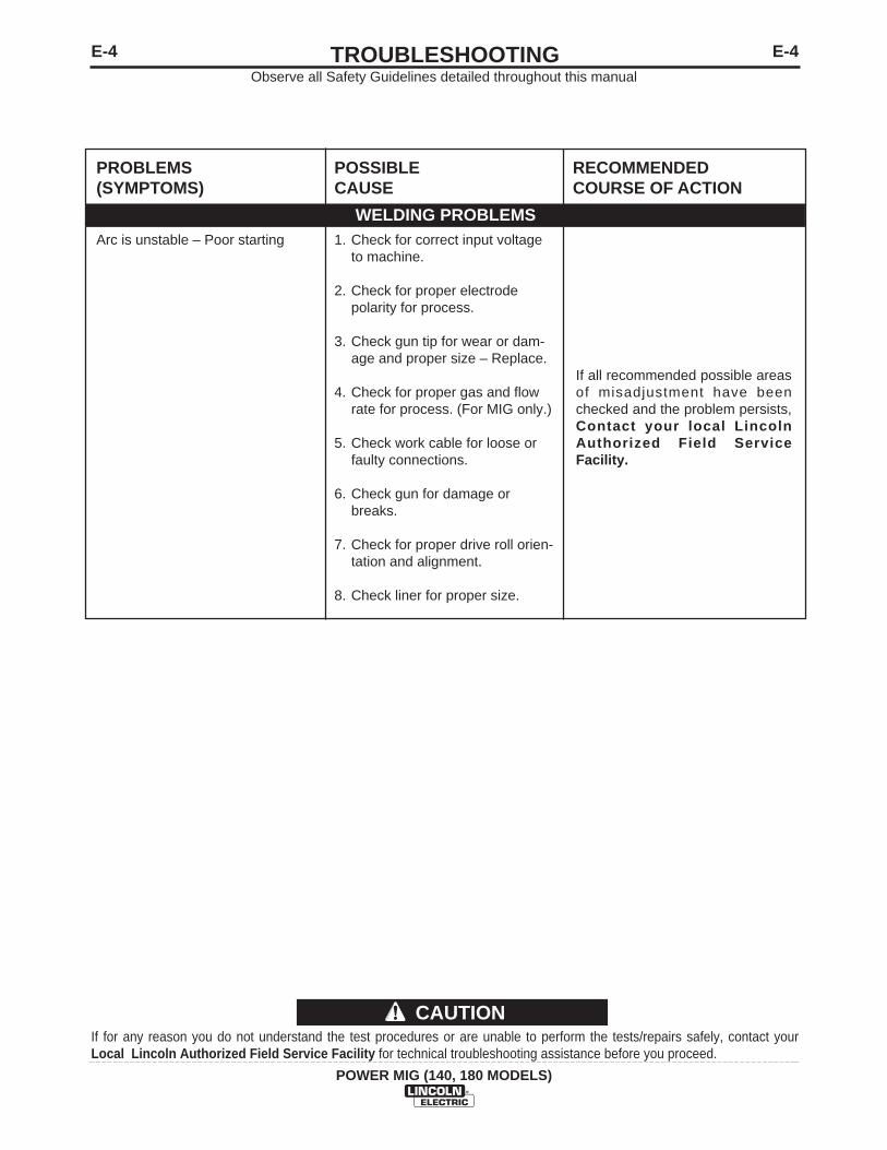
Arc is unstable – Poor starting
POSSIBLECAUSE
1. Check for correct input voltageto machine.
2. Check for proper electrodepolarity for process.
3. Check gun tip for wear or dam-age and proper size – Replace.
4. Check for proper gas and flowrate for process. (For MIG only.)
5. Check work cable for loose orfaulty connections.
6. Check gun for damage orbreaks.
7. Check for proper drive roll orien-tation and alignment.
8. Check liner for proper size.
RECOMMENDEDCOURSE OF ACTION
If all recommended possible areasof misadjustment have beenchecked and the problem persists,Contact your local LincolnAuthorized Field ServiceFacility.
WELDING PROBLEMS
F-1DIAGRAMSF-1
POWER MIG (140, 180 MODELS)
FO
R C
OD
ES
112
54, 1
1255
, 112
56, 1
1257
FO
R C
OD
ES
112
54, 1
1255
, 112
56, 1
1257
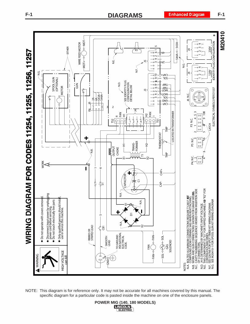
NOTE: This diagram is for reference only. It may not be accurate for all machines covered by this manual. Thespecific diagram for a particular code is pasted inside the machine on one of the enclosure panels.
F-2DIAGRAMSF-2
POWER MIG (180 MODELS)
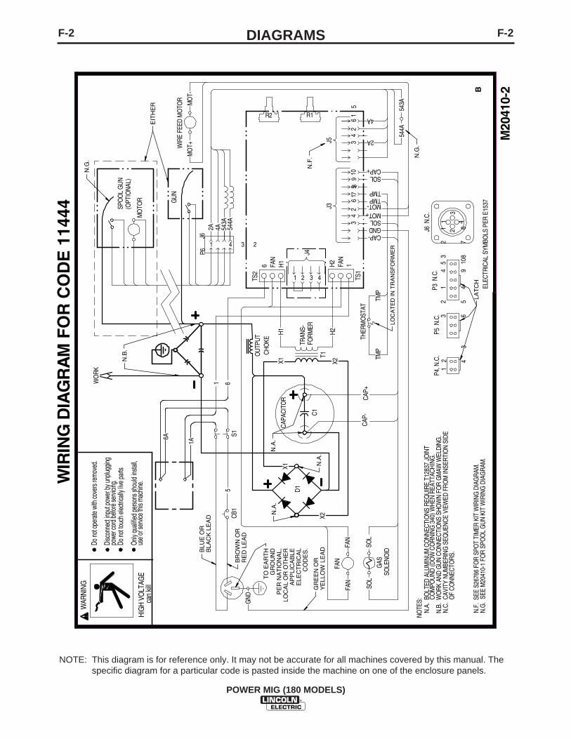
NOTE: This diagram is for reference only. It may not be accurate for all machines covered by this manual. Thespecific diagram for a particular code is pasted inside the machine on one of the enclosure panels.
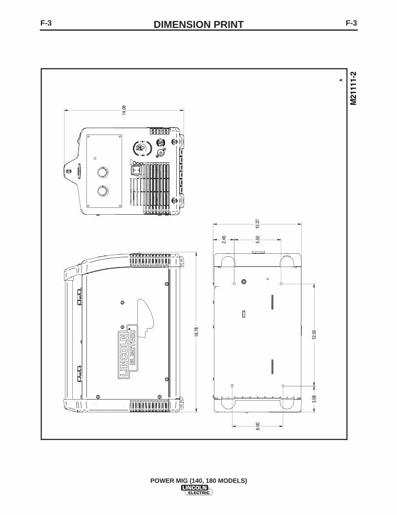
F-3DIMENSION PRINTF-3
POWER MIG (140, 180 MODELS)
M21
111-
2
A
18.7
8
14.0
8
10.3
7
12.0
0
6.00
5.50
3.08
2.46

POWER MIG® (140, 180 MODELS)
P-533P-533
PARTS LIST FOR
POWER MIG®
(140 & 180 Models)
This parts list is provided as an informative guide only.
It was accurate at the time of printing. These pages are only updated on theService Navigator DVD and in Lincoln Electricʼs official Parts Book (BK-34).
When ordering parts, always refer to Lincoln Electricʼs official Parts Book(BK-34) for the latest pages.
02-04-2010POWER MIG® (140, 180 MODELS)
P-533-AP-533-A
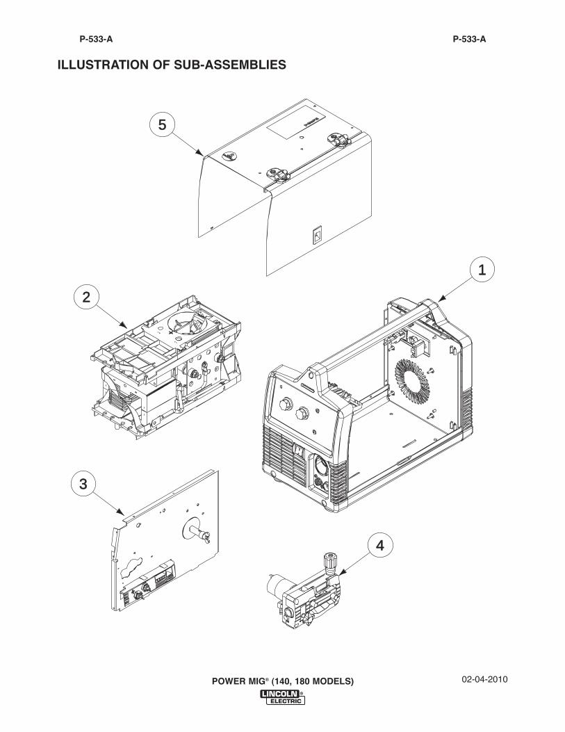
ILLUSTRATION OF SUB-ASSEMBLIES
5
3
2
1
4
01-30-2012POWER MIG® (140, 180 MODELS)
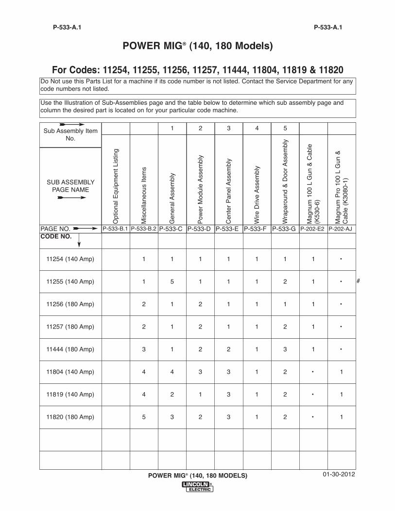
Do Not use this Parts List for a machine if its code number is not listed. Contact the Service Department for anycode numbers not listed.
Use the Illustration of Sub-Assemblies page and the table below to determine which sub assembly page andcolumn the desired part is located on for your particular code machine.
P-533-A.1 P-533-A.1
POWER MIG® (140, 180 Models)
For Codes: 11254, 11255, 11256, 11257, 11444, 11804, 11819 & 11820
CODE NO.
11254 (140 Amp) 1 1 1 1 1 1 1 •
11255 (140 Amp) 1 5 1 1 1 2 1 •
11256 (180 Amp) 2 1 2 1 1 1 1 •
11257 (180 Amp) 2 1 2 1 1 2 1 •
11444 (180 Amp) 3 1 2 2 1 3 1 •
11804 (140 Amp) 4 4 3 3 1 2 • 1
11819 (140 Amp) 4 2 1 3 1 2 • 1
11820 (180 Amp) 5 3 2 3 1 2 • 1
Mag
num
Pro
100
L G
un &
Cab
le (
K30
80-1
)
P-202-AJ
Mag
num
100
L G
un &
Cab
le(K
530-
6)
P-202-E2
Wra
paro
und
& D
oor
Ass
embl
y
P-533-G
5
Wire
Driv
e A
ssem
bly
P-533-F
4
Cen
ter
Pan
el A
ssem
bly
P-533-E
3
Pow
er M
odul
e A
ssem
bly
P-533-D
2
Gen
eral
Ass
embl
y
P-533-C
1
Mis
cella
neou
s Ite
ms
P-533-B.2
Opt
iona
l Equ
ipm
ent
List
ing
P-533-B.1
SUB ASSEMBLY PAGE NAME
PAGE NO.
Sub Assembly ItemNo.
#

DESCRIPTION . . . . . . . . . . . . . . . . . . . . . . . . . . . . . . . . . . . . . . . . . . . . . . . . . . . . . . . . . . . . . . . . . . . . . . .PART NUMBER
Spot Timer Kit . . . . . . . . . . . . . . . . . . . . . . . . . . . . . . . . . . . . . . . . . . . . . . . . . . . . . . .Order K2525-1.045 Innershield Kit . . . . . . . . . . . . . . . . . . . . . . . . . . . . . . . . . . . . . . . . . . . . . . . . . . .Order K2528-1Deluxe Adjustable Gas Regulator & Hose Kit (Codes 11254,11255,11256 & 11257) . . . . . . .Order K586-1Welding Cart . . . . . . . . . . . . . . . . . . . . . . . . . . . . . . . . . . . . . . . . . . . . . . . . . . . . . . . .Order K2275-1Utility Cart . . . . . . . . . . . . . . . . . . . . . . . . . . . . . . . . . . . . . . . . . . . . . . . . . . . . . . . . . .Order K520-1Spool Gun Kit . . . . . . . . . . . . . . . . . . . . . . . . . . . . . . . . . . . . . . . . . . . . . . . . . . . . . . . .Order K2532-1.025 Smooth Drive Roll Kit . . . . . . . . . . . . . . . . . . . . . . . . . . . . . . . . . . . . . . . . . . . . .Order KP2529-1.035 Smooth Drive Roll Kit . . . . . . . . . . . . . . . . . . . . . . . . . . . . . . . . . . . . . . . . . . . . .Order KP2529-2.030/.045 Knurled Drive Roll Kit . . . . . . . . . . . . . . . . . . . . . . . . . . . . . . . . . . . . . . . . .Order KP2529-3.025/.035 Steel Wire Guide Kit . . . . . . . . . . . . . . . . . . . . . . . . . . . . . . . . . . . . . . . . . .Order KP2531-1.045 Steel Wire Guide Kit . . . . . . . . . . . . . . . . . . . . . . . . . . . . . . . . . . . . . . . . . . . . . .Order KP2531-2
02-04-2010POWER MIG® (140, 180 MODELS)
Miscellaneous Options Available for your machine are listed below:# Indicates a change this printing.
P-533-B.1P-533-B.1 OPTIONAL EQUIPMENT LISTING
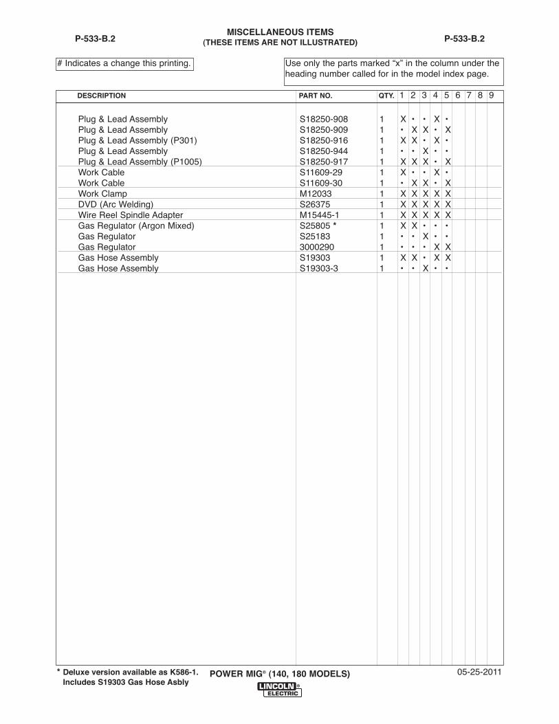
MISCELLANEOUS ITEMS (THESE ITEMS ARE NOT ILLUSTRATED)
Plug & Lead Assembly S18250-908 1 X • • X •Plug & Lead Assembly S18250-909 1 • X X • XPlug & Lead Assembly (P301) S18250-916 1 X X • X •Plug & Lead Assembly S18250-944 1 • • X • •Plug & Lead Assembly (P1005) S18250-917 1 X X X • XWork Cable S11609-29 1 X • • X •Work Cable S11609-30 1 • X X • XWork Clamp M12033 1 X X X X XDVD (Arc Welding) S26375 1 X X X X XWire Reel Spindle Adapter M15445-1 1 X X X X XGas Regulator (Argon Mixed) S25805 * 1 X X • • •Gas Regulator S25183 1 • • X • •Gas Regulator 3000290 1 • • • X XGas Hose Assembly S19303 1 X X • X XGas Hose Assembly S19303-3 1 • • X • •
05-25-2011POWER MIG® (140, 180 MODELS)
Use only the parts marked “x” in the column under theheading number called for in the model index page.
# Indicates a change this printing.
P-533-B.2
DESCRIPTION PART NO. QTY. 1 2 3 4 5 6 7 8 9
P-533-B.2
* Deluxe version available as K586-1.Includes S19303 Gas Hose Asbly
02-04-2010POWER MIG® (140, 180 MODELS)
P-533-CP-533-C
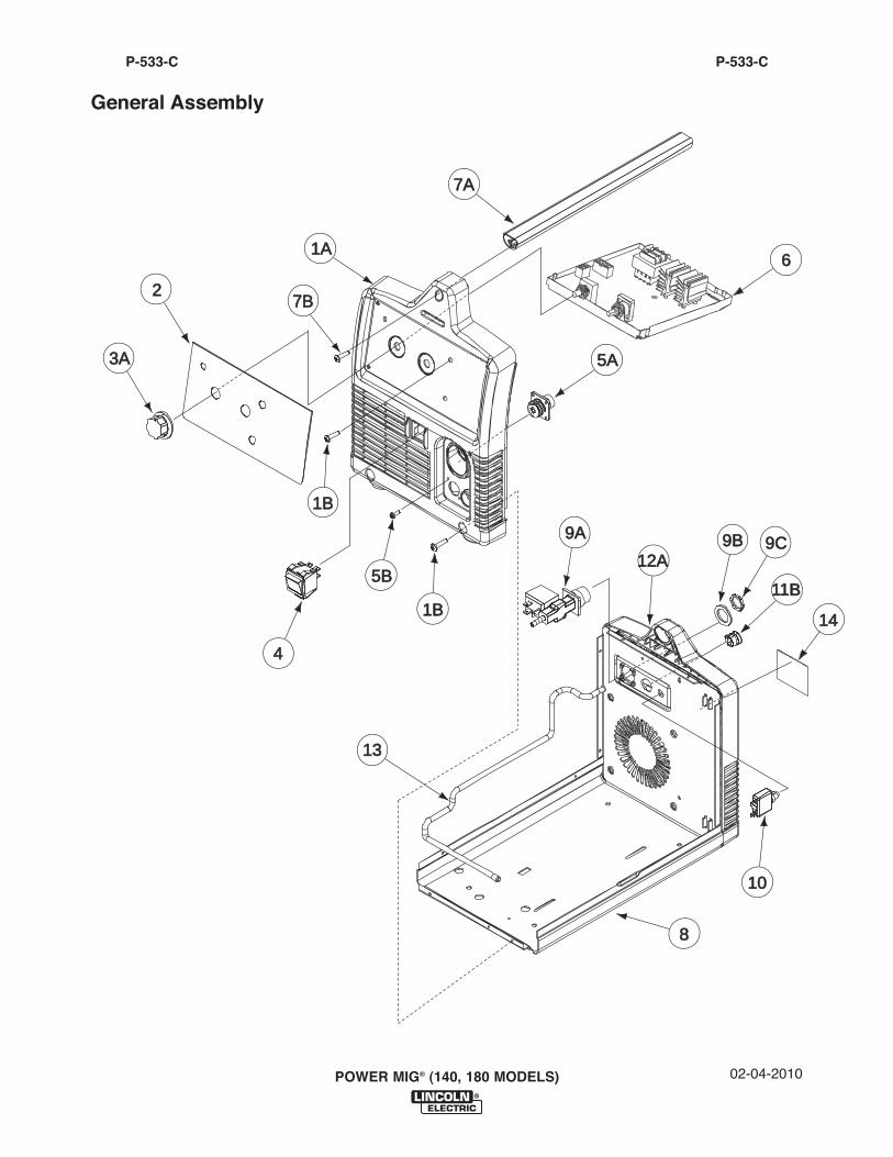
General Assembly
1A1A
1313
1B1B
7A7A
7B7B
4
6
1B1B
12A12A
11B11B
9A9A
8
1010
9B9B 9C9C
5A5A
5B5B
3A3A
2
1414
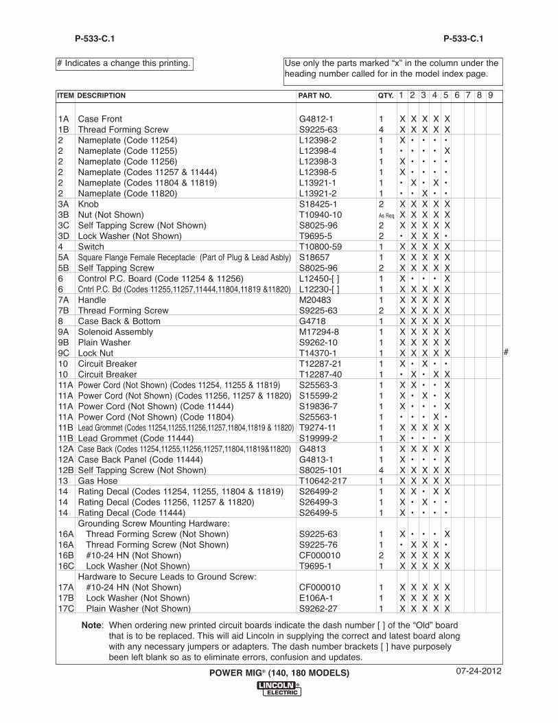
1A Case Front G4812-1 1 X X X X X1B Thread Forming Screw S9225-63 4 X X X X X2 Nameplate (Code 11254) L12398-2 1 X • • • •2 Nameplate (Code 11255) L12398-4 1 • • • • X2 Nameplate (Code 11256) L12398-3 1 X • • • •2 Nameplate (Codes 11257 & 11444) L12398-5 1 X • • • •2 Nameplate (Codes 11804 & 11819) L13921-1 1 • X • X •2 Nameplate (Code 11820) L13921-2 1 • • X • •3A Knob S18425-1 2 X X X X X3B Nut (Not Shown) T10940-10 As Req X X X X X3C Self Tapping Screw (Not Shown) S8025-96 2 X X X X X3D Lock Washer (Not Shown) T9695-5 2 • X X X •4 Switch T10800-59 1 X X X X X5A Square Flange Female Receptacle (Part of Plug & Lead Asbly) S18657 1 X X X X X5B Self Tapping Screw S8025-96 2 X X X X X6 Control P.C. Board (Code 11254 & 11256) L12450-[ ] 1 X • • • X6 Cntrl P.C. Bd (Codes 11255,11257,11444,11804,11819 &11820) L12230-[ ] 1 X X X X X7A Handle M20483 1 X X X X X7B Thread Forming Screw S9225-63 2 X X X X X8 Case Back & Bottom G4718 1 X X X X X9A Solenoid Assembly M17294-8 1 X X X X X9B Plain Washer S9262-10 1 X X X X X9C Lock Nut T14370-1 1 X X X X X10 Circuit Breaker T12287-21 1 X • X • •10 Circuit Breaker T12287-40 1 • X • X X11A Power Cord (Not Shown) (Codes 11254, 11255 & 11819) S25563-3 1 X X • • X11A Power Cord (Not Shown) (Codes 11256, 11257 & 11820) S15599-2 1 X • X • X11A Power Cord (Not Shown) (Code 11444) S19836-7 1 X • • • X11A Power Cord (Not Shown) (Code 11804) S25563-1 1 • • • X •11B Lead Grommet (Codes 11254,11255,11256,11257,11804,11819 & 11820) T9274-11 1 X X X X X11B Lead Grommet (Code 11444) S19999-2 1 X • • • X12A Case Back (Codes 11254,11255,11256,11257,11804,11819&11820) G4813 1 X X X X X12A Case Back Panel (Code 11444) G4813-1 1 X • • • X12B Self Tapping Screw (Not Shown) S8025-101 4 X X X X X13 Gas Hose T10642-217 1 X X X X X14 Rating Decal (Codes 11254, 11255, 11804 & 11819) S26499-2 1 X X • X X14 Rating Decal (Codes 11256, 11257 & 11820) S26499-3 1 X • X • •14 Rating Decal (Code 11444) S26499-5 1 X • • • •
Grounding Screw Mounting Hardware:16A Thread Forming Screw (Not Shown) S9225-63 1 X • • • X16A Thread Forming Screw (Not Shown) S9225-76 1 • X X X •16B #10-24 HN (Not Shown) CF000010 2 X X X X X16C Lock Washer (Not Shown) T9695-1 1 X X X X X
Hardware to Secure Leads to Ground Screw:17A #10-24 HN (Not Shown) CF000010 1 X X X X X17B Lock Washer (Not Shown) E106A-1 1 X X X X X17C Plain Washer (Not Shown) S9262-27 1 X X X X X
07-24-2012POWER MIG® (140, 180 MODELS)
Use only the parts marked “x” in the column under theheading number called for in the model index page.
# Indicates a change this printing.
P-533-C.1
ITEM DESCRIPTION PART NO. QTY. 1 2 3 4 5 6 7 8 9
P-533-C.1
Note: When ordering new printed circuit boards indicate the dash number [ ] of the “Old” boardthat is to be replaced. This will aid Lincoln in supplying the correct and latest board alongwith any necessary jumpers or adapters. The dash number brackets [ ] have purposelybeen left blank so as to eliminate errors, confusion and updates.
#
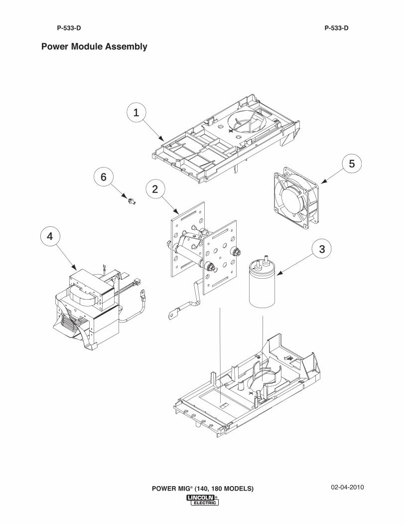
02-04-2010POWER MIG® (140, 180 MODELS)
P-533-DP-533-D
Power Module Assembly
4
1
62
3
5
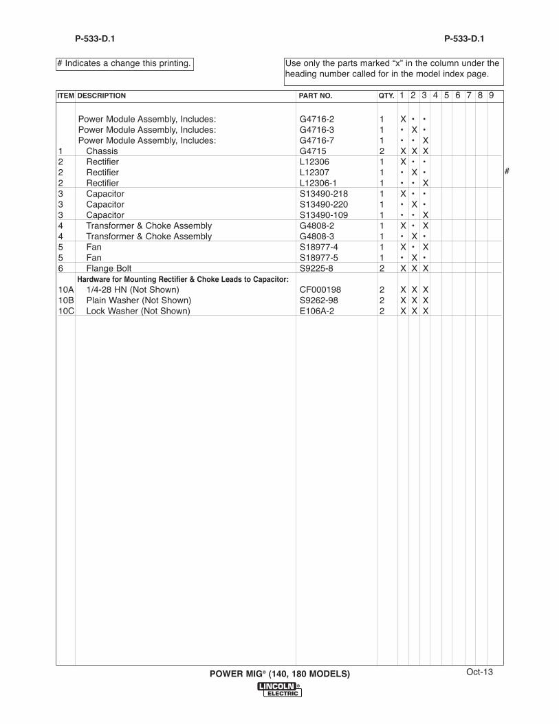
Power Module Assembly, Includes: G4716-2 1 X • •Power Module Assembly, Includes: G4716-3 1 • X •Power Module Assembly, Includes: G4716-7 1 • • X
1 Chassis G4715 2 X X X2 Rectifier L12306 1 X • •2 Rectifier L12307 1 • X •2 Rectifier L12306-1 1 • • X3 Capacitor S13490-218 1 X • •3 Capacitor S13490-220 1 • X •3 Capacitor S13490-109 1 • • X4 Transformer & Choke Assembly G4808-2 1 X • X4 Transformer & Choke Assembly G4808-3 1 • X •5 Fan S18977-4 1 X • X5 Fan S18977-5 1 • X •6 Flange Bolt S9225-8 2 X X X
Hardware for Mounting Rectifier & Choke Leads to Capacitor:10A 1/4-28 HN (Not Shown) CF000198 2 X X X10B Plain Washer (Not Shown) S9262-98 2 X X X10C Lock Washer (Not Shown) E106A-2 2 X X X
Oct-13POWER MIG® (140, 180 MODELS)
Use only the parts marked “x” in the column under theheading number called for in the model index page.
# Indicates a change this printing.
P-533-D.1
ITEM DESCRIPTION PART NO. QTY. 1 2 3 4 5 6 7 8 9
P-533-D.1
#
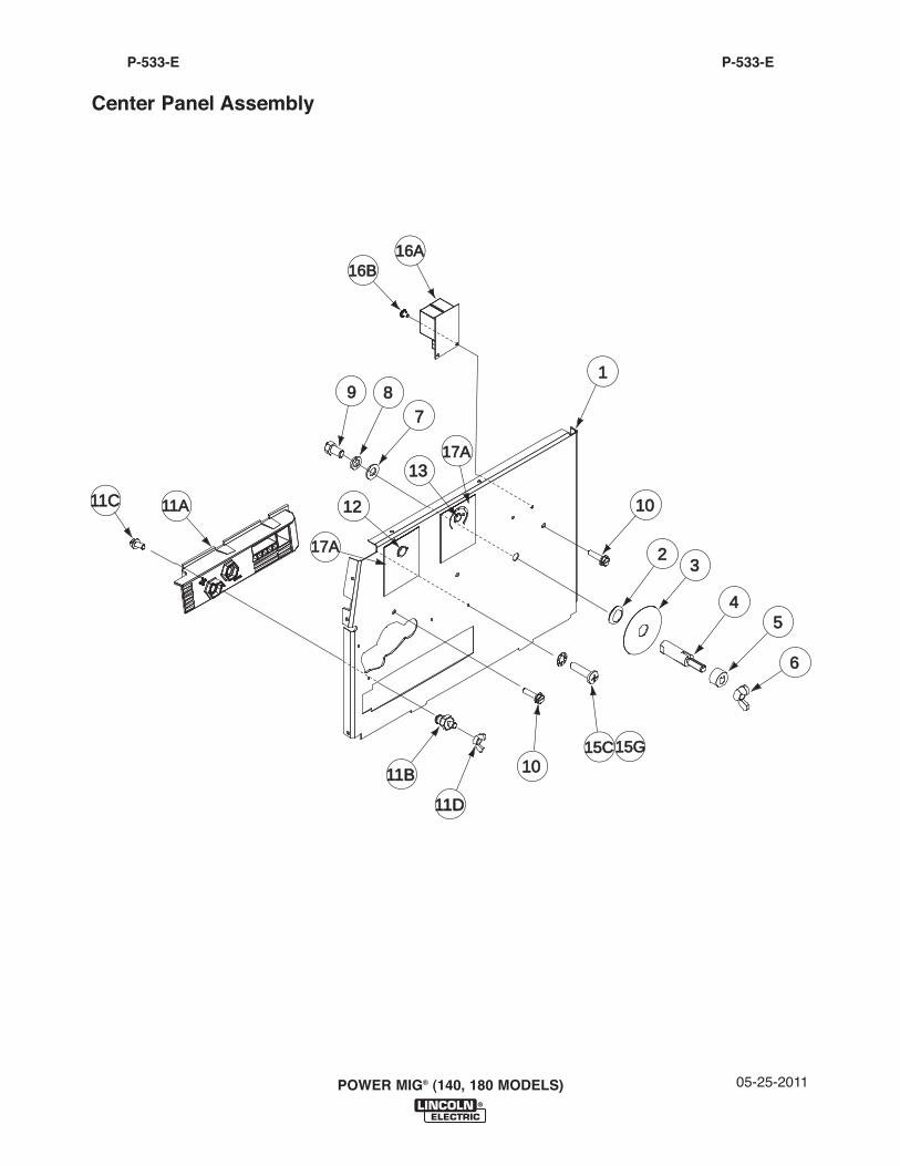
05-25-2011POWER MIG® (140, 180 MODELS)
P-533-EP-533-E
Center Panel Assembly
1
1010
1010
23
45
6
11D11D
11B11B
15C15C15G15G
16A16A16B16B
17A17A
17A17A
1212
1313
789
11C11C 11A11A
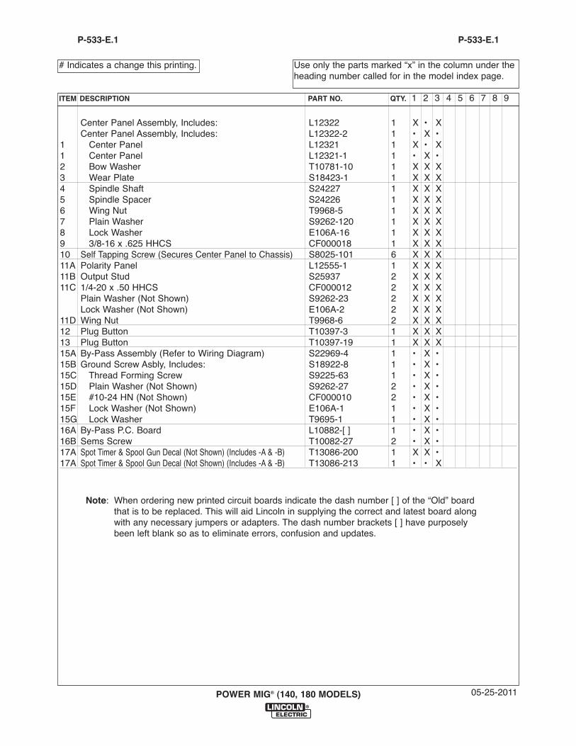
Center Panel Assembly, Includes: L12322 1 X • XCenter Panel Assembly, Includes: L12322-2 1 • X •
1 Center Panel L12321 1 X • X1 Center Panel L12321-1 1 • X •2 Bow Washer T10781-10 1 X X X3 Wear Plate S18423-1 1 X X X4 Spindle Shaft S24227 1 X X X5 Spindle Spacer S24226 1 X X X6 Wing Nut T9968-5 1 X X X7 Plain Washer S9262-120 1 X X X8 Lock Washer E106A-16 1 X X X9 3/8-16 x .625 HHCS CF000018 1 X X X10 Self Tapping Screw (Secures Center Panel to Chassis) S8025-101 6 X X X11A Polarity Panel L12555-1 1 X X X11B Output Stud S25937 2 X X X11C 1/4-20 x .50 HHCS CF000012 2 X X X
Plain Washer (Not Shown) S9262-23 2 X X XLock Washer (Not Shown) E106A-2 2 X X X
11D Wing Nut T9968-6 2 X X X12 Plug Button T10397-3 1 X X X13 Plug Button T10397-19 1 X X X15A By-Pass Assembly (Refer to Wiring Diagram) S22969-4 1 • X •15B Ground Screw Asbly, Includes: S18922-8 1 • X •15C Thread Forming Screw S9225-63 1 • X •15D Plain Washer (Not Shown) S9262-27 2 • X •15E #10-24 HN (Not Shown) CF000010 2 • X •15F Lock Washer (Not Shown) E106A-1 1 • X •15G Lock Washer T9695-1 1 • X •16A By-Pass P.C. Board L10882-[ ] 1 • X •16B Sems Screw T10082-27 2 • X •17A Spot Timer & Spool Gun Decal (Not Shown) (Includes -A & -B) T13086-200 1 X X •17A Spot Timer & Spool Gun Decal (Not Shown) (Includes -A & -B) T13086-213 1 • • X
05-25-2011POWER MIG® (140, 180 MODELS)
Use only the parts marked “x” in the column under theheading number called for in the model index page.
# Indicates a change this printing.
P-533-E.1
ITEM DESCRIPTION PART NO. QTY. 1 2 3 4 5 6 7 8 9
P-533-E.1
Note: When ordering new printed circuit boards indicate the dash number [ ] of the “Old” boardthat is to be replaced. This will aid Lincoln in supplying the correct and latest board alongwith any necessary jumpers or adapters. The dash number brackets [ ] have purposelybeen left blank so as to eliminate errors, confusion and updates.
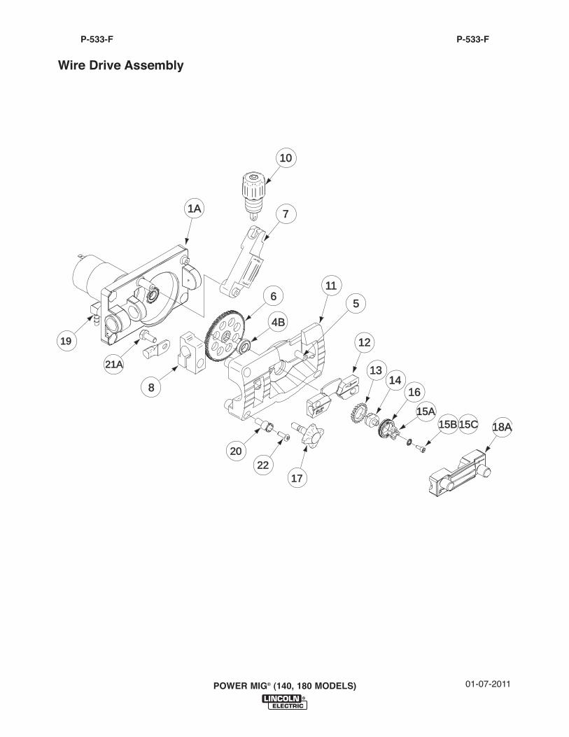
POWER MIG® (140, 180 MODELS)
P-533-FP-533-F
Wire Drive Assembly
1A1A 7
1010
21A21A
20202222
1717
65
4B4B
1111
1212
8
1919
13131414
1616
15A15A15B15B 15C15C 18A18A
01-07-2011
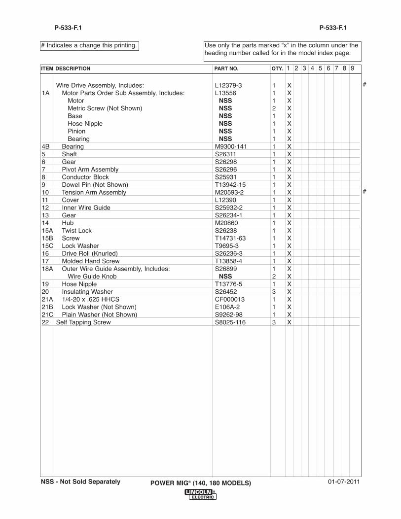
Wire Drive Assembly, Includes: L12379-3 1 X1A Motor Parts Order Sub Assembly, Includes: L13556 1 X
Motor NSS 1 XMetric Screw (Not Shown) NSS 2 XBase NSS 1 XHose Nipple NSS 1 XPinion NSS 1 XBearing NSS 1 X
4B Bearing M9300-141 1 X5 Shaft S26311 1 X6 Gear S26298 1 X7 Pivot Arm Assembly S26296 1 X8 Conductor Block S25931 1 X9 Dowel Pin (Not Shown) T13942-15 1 X10 Tension Arm Assembly M20593-2 1 X11 Cover L12390 1 X12 Inner Wire Guide S25932-2 1 X13 Gear S26234-1 1 X14 Hub M20860 1 X15A Twist Lock S26238 1 X15B Screw T14731-63 1 X15C Lock Washer T9695-3 1 X16 Drive Roll (Knurled) S26236-3 1 X17 Molded Hand Screw T13858-4 1 X18A Outer Wire Guide Assembly, Includes: S26899 1 X
Wire Guide Knob NSS 2 X19 Hose Nipple T13776-5 1 X20 Insulating Washer S26452 3 X21A 1/4-20 x .625 HHCS CF000013 1 X21B Lock Washer (Not Shown) E106A-2 1 X21C Plain Washer (Not Shown) S9262-98 1 X22 Self Tapping Screw S8025-116 3 X
01-07-2011POWER MIG® (140, 180 MODELS)
Use only the parts marked “x” in the column under theheading number called for in the model index page.
# Indicates a change this printing.
P-533-F.1
ITEM DESCRIPTION PART NO. QTY. 1 2 3 4 5 6 7 8 9
P-533-F.1
NSS - Not Sold Separately
#
#
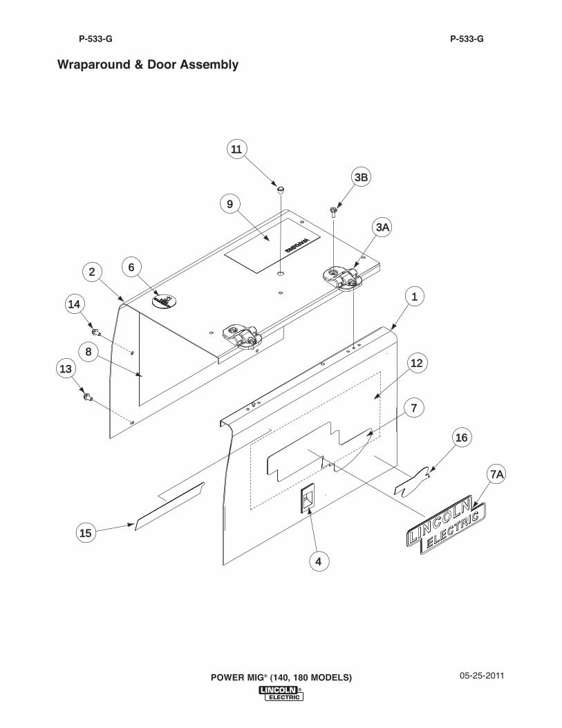
05-25-2011POWER MIG® (140, 180 MODELS)
P-533-GP-533-G
Wraparound & Door Assembly
1
4
1515
62
8
9
7
1616
1111
1414
1313
3A3A
3B3B
7A7A
1212
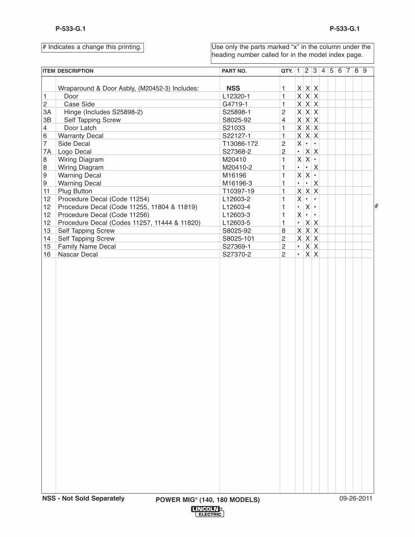
Wraparound & Door Asbly, (M20452-3) Includes: NSS 1 X X X1 Door L12320-1 1 X X X2 Case Side G4719-1 1 X X X3A Hinge (Includes S25898-2) S25898-1 2 X X X3B Self Tapping Screw S8025-92 4 X X X4 Door Latch S21033 1 X X X6 Warranty Decal S22127-1 1 X X X7 Side Decal T13086-172 2 X • •7A Logo Decal S27368-2 2 • X X8 Wiring Diagram M20410 1 X X •8 Wiring Diagram M20410-2 1 • • X9 Warning Decal M16196 1 X X •9 Warning Decal M16196-3 1 • • X11 Plug Button T10397-19 1 X X X12 Procedure Decal (Code 11254) L12603-2 1 X • •12 Procedure Decal (Code 11255, 11804 & 11819) L12603-4 1 • X •12 Procedure Decal (Code 11256) L12603-3 1 X • •12 Procedure Decal (Codes 11257, 11444 & 11820) L12603-5 1 • X X13 Self Tapping Screw S8025-92 8 X X X14 Self Tapping Screw S8025-101 2 X X X15 Family Name Decal S27369-1 2 • X X16 Nascar Decal S27370-2 2 • X X
09-26-2011POWER MIG® (140, 180 MODELS)
Use only the parts marked “x” in the column under theheading number called for in the model index page.
# Indicates a change this printing.
P-533-G.1
ITEM DESCRIPTION PART NO. QTY. 1 2 3 4 5 6 7 8 9
P-533-G.1
NSS - Not Sold Separately
#
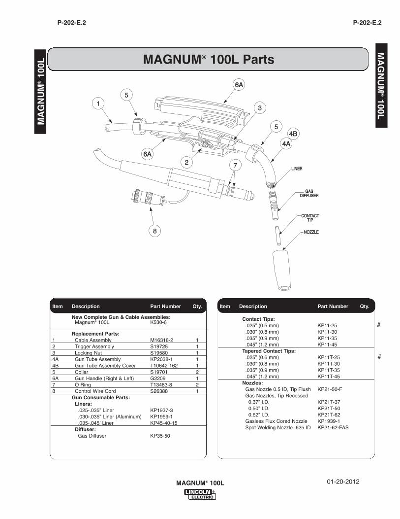
Item Description Part Number Qty.
New Complete Gun & Cable Assemblies:Magnum® 100L K530-6
Replacement Parts:1 Cable Assembly M16318-2 12 Trigger Assembly S19725 13 Locking Nut S19580 14A Gun Tube Assembly KP2038-1 14B Gun Tube Assembly Cover T10642-162 15 Collar S19701 26A Gun Handle (Right & Left) G2209 17 O Ring T13483-8 28 Control Wire Cord S26388 1
Gun Consumable Parts:Liners:
.025-.035” Liner KP1937-3
.030-.035” Liner (Aluminum) KP1959-1
.035-.045ʼ Liner KP45-40-15Diffuser:
Gas Diffuser KP35-50
Item Description Part Number Qty.Item Description Part Number Qty
Item Description Part Number Qty.
Contact Tips:.025” (0.5 mm) KP11-25.030” (0.8 mm) KP11-30.035” (0.9 mm) KP11-35.045” (1.2 mm) KP11-45
Tapered Contact Tips:.025” (0.6 mm) KP11T-25.030” (0.8 mm) KP11T-30.035” (0.9 mm) KP11T-35.045” (1.2 mm) KP11T-45
Nozzles:Gas Nozzle 0.5 ID, Tip Flush KP21-50-FGas Nozzles, Tip Recessed
0.37” I.D. KP21T-370.50” I.D. KP21T-500.62” I.D. KP21T-62
Gasless Flux Cored Nozzle KP1939-1Spot Welding Nozzle .625 ID KP21-62-FAS
MAGNUM® 100L Parts
MAGNUM® 100L 01-20-2012
GASGASDIFFUSERDIFFUSER
CONTACTCONTACTTIPTIP
NOZZLENOZZLE
LINERLINER
5
3
2 7
6A6A
6A6A
4A4A
4B4B
5
8
1
MA
GN
UM
®100L
MA
GN
UM
®10
0L
P-202-E.2 P-202-E.2
#
#

MAGNUM® 100L
NOTES

POWER MIG® (140, 180 MODELS)
NOTES

NOTES
POWER MIG (140, 180 MODELS)

CUSTOMER ASSISTANCE POLICY
The business of The Lincoln Electric Company is manufacturing andselling high quality welding equipment, consumables, and cuttingequipment. Our challenge is to meet the needs of our customers andto exceed their expectations. On occasion, purchasers may askLincoln Electric for advice or information about their use of ourproducts. We respond to our customers based on the best informationin our possession at that time. Lincoln Electric is not in a position towarrant or guarantee such advice, and assumes no liability, withrespect to such information or advice. We expressly disclaim anywarranty of any kind, including any warranty of fitness for anycustomer’s particular purpose, with respect to such information oradvice. As a matter of practical consideration, we also cannot assumeany responsibility for updating or correcting any such information oradvice once it has been given, nor does the provision of informationor advice create, expand or alter any warranty with respect to the saleof our products.
Lincoln Electric is a responsive manufacturer, but the selection anduse of specific products sold by Lincoln Electric is solely within thecontrol of, and remains the sole responsibility of the customer. Manyvariables beyond the control of Lincoln Electric affect the resultsobtained in applying these types of fabrication methods and servicerequirements.
Subject to Change – This information is accurate to the best of ourknowledge at the time of printing. Please refer to www.lincolnelectric.com for any updated information.