Operator’s Manual - Parts, Service and Operations...
90
Operator’s Manual Serial number range First Edition First Printing Part No. 57.0303.5159 FIXED HOOK on PLATE From serial n.: 61606 With Maintenance Information 4000mm/900kg JIB From serial n.: 61902 3000kg HOIST From serial n.: 61958 2000mm/2000kg JIB From serial n.: 61903
Transcript of Operator’s Manual - Parts, Service and Operations...

Operator’s Manual
Serial number range
First Edition
First Printing
Part No. 57.0303.5159
FIXED HOOK on PLATE
From serial n.: 61606
With Maintenance
Information
4000mm/900kg JIB From serial n.: 61902
3000kg HOIST From serial n.: 61958
2000mm/2000kg JIB From serial n.: 61903

Operator’s Manual
2 HOOK - JIB - HOIST Part No. 57.0303.5159
First Edition - First Printing
Contact us:ZONA INDUSTRIALE I-06019 UMBERTIDE (PG) - ITALYTelephone +39 075 941811Telefax +39 075 9415382
Technical Assistance ServiceTelephone: +39 075 9418129 +39 075 9418175e-mail: [email protected]
ImportantRead, understand and obey these safety rules and operating instructions before operating the machine. Only trained and qualified personnel shall be authorized to operate the machine. This manual shall be kept with the machine at all times.
For any further information, please call Terexlift.
Contents
Introduction ..........................................Page 3Equipment Identification ......................Page 5Labels And Plates Applied...................Page 7Safety Precautions ..............................Page 9 Equipment Description ..........................Page 17 Inspections ..........................................Page 23 Operating Instructions .........................Page 27 Maintenance ........................................Page 49 Faults And Troubleshooting.................Page 53 Specifications ......................................Page 55 Load Charts .........................................Page 59Diagrams And Schemes ......................Page 81Beaufort Wind Scale ............................Page 83 Tables of Material ................................Page 85 EC Declaration of Conformity ..............Page 87Routine Check List ..............................Page 89
Original Instructions First Edition: First Printing, May 2011
For the electronic version of this manual visit www.genielift.com/operator_manuals.asp
Copyright © 2011 TEREXLIFT srlAll rights reserved
Produced by: TEREXLIFT Technical Literature Dept.Umbertide (PG) Italy
First Edition - First Printing Operator’s Manual
Part No. 57.0303.5159 HOOK - JIB - HOIST 3
Introduction
Symbols
Safety alert symbol: used to alert you to potential personal injury hazards. Obey all safety messages that follow this symbol to avoid possible injury or death
DANGER Red: indicates a hazardous situation which, if not avoided, will result in death or serious injury.
WARNING Orange: indicates a hazardous situation which, if not avoided, could result in death or serious injury.
CAUTION Yellow : indicates a hazardous situation which, if not avoided, could result in minor or moderate injury.
NOTICE Blue: indicates a hazardous situation which, if not avoided, could result in property damage.
PROTECT THEENVIRONMENT Green: used to draw the
a t tent ion to important information on environment protection.

Operator’s Manual
4 HOOK - JIB - HOIST Part No. 57.0303.5159
First Edition - First Printing
Intentionally blank page

First Edition - First Printing Operator’s Manual
Part No. 57.0303.5159 HOOK - JIB - HOIST 5
Check that the Operator's Manual refers to the delivered equipment.
DESIGNATION: FIXED HOOK ON PLATE
JIB HOIST
MODEL: Fixed Hook on Plate
4000mm/900kg Hydraulic Jib
4000mm/900kg Jib
2000mm/400kg Jib
2000mm/2000kg Jib
3000kg Hoist
MANUFACTURER:
TEREXLIFT srlZona Industriale - I-06019 UMBERTIDE (PG) - ITALY
Enrolled in the register of companies at the Court of Perugia under no. 4823
C.C.I.A.A. 102886
Fiscal Code/V.A.T. no. 00249210543
APPLICABLE STANDARDSFor the operator’s safety, the following standards were obeyed during the risk assessment of the handler fitted with telescopic boom norme:
Directive Title
2006/42/EC Machinery Directive
Standard TitleEN 1459:1988/A2:2009 Safety of Industrial trucks -
Self- propelled variable reach trucks.
Equipment Identifi cation
IDENTIFICATION PLATEThe following data plate is applied on the equipment.
The identification plate contains model, designation, serial number, weight, payload and year of manufacture, as shown below.
Model:
Model Year:
Designation:
Serial number:
Manufacture Year:
Manufacturer:Terexlift srl z.i.Buzzacchero06019 Umbertide, Italy
MMMMMMMMMMMMMMMMMMMMMMMMMMMMMM
AAAA
MMMMMMMMMMMMMMMMMMMMMMMMMMMMMM
AAAAAAAAAA
AAAA
AAAAAAAAA
MMMMMMMMM
AAAAAAAAA
Country of Manufacture: ITALY
Unit mass (Kg) :
Rated capacity:
Center of gravity from mounting face (mm):
MMMMMMMMMMMMMMMMMMMMMMMMMMMMMM
MMMM
Operator’s Manual
6 HOOK - JIB - HOIST Part No. 57.0303.5159
First Edition - First Printing
Intentionally blank page

First Edition - First Printing Operator’s Manual
Part No. 57.0303.5159 HOOK - JIB - HOIST 7
Labels And Plates Applied
Ref. Decal Code Description Qt.
1 /PLATE_Maximum payload.ONLY for 4000mm/900kg JIB
1
2 09.4618.1346 Entanglement Hazard 1
A/
IDENTIFICATION PLATE 1
900 kg
Use the pictures on these pages to verify that all labels and plates are legible and in place.The following chart shows quantities and description too.
Model:
Model Year:
Designation:
Serial number:
Manufacture Year:
Manufacturer:Terexlift srl z.i.Buzzacchero06019 Umbertide, Italy
MMMMMMMMMMMMMMMMMMMMMMMMMMMMMM
AAAA
MMMMMMMMMMMMMMMMMMMMMMMMMMMMMM
AAAAAAAAAA
AAAA
AAAAAAAAA
MMMMMMMMM
AAAAAAAAA
Country of Manufacture: ITALY
Unit mass (Kg) :
Rated capacity:
Center of gravity from mounting face (mm):
MMMMMMMMMMMMMMMMMMMMMMMMMMMMMM
MMMM
�
09.4618.1346

Operator’s Manual
8 HOOK - JIB - HOIST Part No. 57.0303.5159
First Edition - First Printing
Intentionally blank page

First Edition - First Printing Operator’s Manual
Part No. 57.0303.5159 HOOK - JIB - HOIST 9
DAMAGED MACHINE HAZARDS
• Do not use a damaged or modified equipment.• Do a thorough pre-operation inspection of the
equipment and test all functions before each work shift. Tag and remove from service a damaged or modified equipment.
• Make sure that all maintenance jobs have been carried out as specified in this manual and in the telehandler's specific manuals.
• Make sure that all plates are in place and legible.• Make sure that the operator’s manual is intact,
legible and placed in the special container located in the machine.
PERSONAL INJURY HAZARDS
• Do not operate the equipment in case of hydraulic oil or air leak of the telehandler. Air or hydraulic oil leaks can penetrate or burn the skin.
• Always operate the telehandler in a well ventilated area to avoid carbon monoxide poisoning.
• Do not lower the boom if the area underneath is not clear of personnel or obstructions.
SAFETY DEVICES
Several safety devices have been fitted to the telehandler. They must never be tampered with or removed.Regularly check the efficiency of such devices.In case of faults, stop working immediately and proceed in replacing the modified device.For the checking procedures, read chap. "Maintenance" of the telehandler Operator's Manual.
MOMENT LIMITING SYSTEMThe moment limiting system has been developed to help the operator to maintain the telehandler longitudinal stability. Audible and visual messages are provided when the limits of longitudinal stability are being approached.However this device cannot replace the experience of the operator. It is up to the user to adopt the necessary safety measures to work within the rated limits of the machine.
Safety Precautions

Operator’s Manual
10 HOOK - JIB - HOIST Part No. 57.0303.5159
First Edition - First Printing
GENERAL REMARKS
Most accidents occurring while working, repairing or maintaining machines, are caused by not complying with the basic safety precautions.Therefore, it is necessary to pay steady attention to the potential hazards and the effects that may come of operations carried out on the telehandler.
If you recognise hazardous situations, you can prevent accidents!
DANGERThe instructions given in this handbook are the ones established by TEREXLIFT. They do not exclude other safe and most convenient ways for the telehandler and/or the equipment installation, operation and maintenance that take into account the available spaces and means.
If you decide to follow instructions other than those given in this manual, you shall absolutely:• be sure that the operations you are going to carry
out are not explicitly forbidden;• be sure that the methods are safe, say, in
compliance with the rules and provisions given in this section;
• be sure that the methods cannot damage the telehandler and/or the equipment, directly or indirectly, or make it unsafe;
• contact TEREXLIFT Assistance Service for any suggestion and the necessary written permission.
Not observing the instructions and safety rules in this manual may result in death or serious injury.
Do not operate the equipment unless:
• You learn and practice the principles of safe work equipment operation contained in this operator’s manual.1. Avoid hazardous situations. Read and
understand the safety instructions before going on to the next chapter.
2. Always perform a pre-operation inspection.3. Always test the equipment functions prior
to use.4. Inspect the work place.5. Only use the equipment for the intended
application. • Read, understand and obey the manufacturer’s
instructions and the safety rules, the safety and operator’s manuals, and the decals applied on the equipment.
• Read, understand and obey the employer’s safety rules and worksite regulations.
• Read, understand and obey the applicable national regulations.
• Only trained personnel informed on the safety rules can operate the equipment.
Safety Precautions
NOTICE

First Edition - First Printing Operator’s Manual
Part No. 57.0303.5159 HOOK - JIB - HOIST 11
REQUISITES OF THE PERSONNEL IN CHARGE
Requisites of the TELEHANDLER OPERATORSThe operators who use the telehandler and/or the equipment, regularly or occasionally, shall have the following prerequisites:health: before and during any operation, operators shall never take alcoholic beverages, medicines or other substances that may alter their psycho-physical conditions and, consequently, their working abilities.physical: good eyesight, acute hearing, good co-ordination and ability to carry out all required operations in a safe way, according to the instructions of this manual.mental: ability to understand and apply the enforced rules, regulations and safety precautions. They shall be careful and sensible for their own as well as for the others’ safety and shall desire to carry out the work correctly and in a responsible way.emotional: they shall keep calm and always be able to evaluate their own physical and mental conditions.training: they shall read and be familiar with this handbook, its enclosed graphs and diagrams. They shall be skilled and trained about the telehandler and/or the equipment use.
NOTICEThe operator shall have a licence (or a driving licence) when provided for by the laws enforced in the country where the machine works. Please, ask the competent bodies.
Requisites of the SERVICEMENThe personnel charged with the telehandler and the equipment maintenance shall be qualified, specialized in their maintenance, and shall have the following prerequisites:physical: good eyesight, acute hearing, good co-ordination and ability to carry out all required maintenance operations in a safe way, according to this manual.mental: ability to understand and apply the enforced rules, regulations and safety precautions. They shall be careful and sensible for their own as well as for the others’ safety and shall desire to carry out the work correctly and in a responsible way.training: they shall read and be familiar with this handbook, its enclosed graphs and diagrams, the identification and warning plates. They shall be skilled and trained about the machine functioning.
NOTICEFrom a technical point of view, the ordinary maintenance of the telehandler and/or the equipment is not a complex intervention and can be carried out by the operator too, provided he has a basic knowledge of mechanics.
Safety Precautions

Operator’s Manual
12 HOOK - JIB - HOIST Part No. 57.0303.5159
First Edition - First Printing
WORKING CLOTHESDuring work, but especially when maintaining or repairing the machine, operators must wear suitable protective clothing:• Overalls or any other comfortable garments.
Operators should not wear clothes with large sleeves or objects that can get stuck in moving parts of the machine.
• Ear-protectors or equivalent equipment.• Protective helmet.• Protective gloves.• Working shoes.
OTHER DANGERS Hazards on the JOBSITE
Always take into account the features of the job site where you are going to work:• Always examine the working area and compare
it with the telehandler dimensions in the different configurations.
DANGERThe telehandler is not electrically insulated and does not provide protection from contact with or proximity to electrical power lines.Always keep at a minimum safe distance from the telescopic boom and the lifted load. Electrical hazards!• Keep away from the machine in case of contact
with energized power lines. Personnel on the ground must never touch or operate the telehandler until energized power lines are shut off.
DANGERDo not, at any time, use the machine during a storm.
WARNINGOperator have to survey his/her field of vision when operating the telehandler.
Use only type-approved working clothing in good condition.
Personal PROTECTIVE EQUIPMENTUnder special working conditions, the following personal protective equipment should be used:• Breathing set (or dust mask).• Goggles or facial masks.
DEATH OR INJURY CAN RESULT FROMCONTACTING ELECTRIC POWER LINES.
ALWAYS CONTACT THE ELECTRIC POWER LINESOWNER. THE ELECTRIC POWER SHALL BEDISCONNECTED OR THE POWER LINES MOVEDOR INSULATED BEFORE MACHINE OPERATIONSBEGINPOWER LINE VOLTAGE REQUIRED CLEARANCE
0 to 50 kV 10 ft 3.00 m50 to 200 kV 15 ft 4.60 m
200 to 350 kV 20 ft 6.10 m350 to 500 kV 25 ft 7.62 m500 to 750 kV 35 ft 10.67 m750 to 1000 kV 45 ft 13.72 m
Safety Precautions

First Edition - First Printing Operator’s Manual
Part No. 57.0303.5159 HOOK - JIB - HOIST 13
OPERATION or MAINTENANCE hazardsBefore any operation, following precautions should be taken:• First of all, make sure that the maintenance
interventions have been carried out with care according to the established schedule.
WARNINGSet the telehandler to working configuration and level it.
• Ensure you have enough fuel to avoid a sudden stop of the engine, especially during a crucial manoeuvre.
• Clean instruments, data plates, lights and the cab windscreen thoroughly.
• Check the correct functioning of all the safety devices installed on the telehandler and/or on the equipment.
• In case of troubles or difficulties, inform the foreman at once. Never start working under unsafe conditions.
• Do not carry out any repair work in a makeshift way to start working!
During work, and especially maintenance, always pay the greatest attention:• Do not walk or stop under raised loads or machine
parts supported by hydraulic cylinders or ropes only.
• Keep the machine handholds and access steps always clean from oil, grease or dirt to prevent falls or slips.
Safety Precautions
• When entering/leaving the cab or other raised parts, always face the machine; never turn the back.
• When carrying out operations at hazardous heights (over 1.5 meters from the ground), always use approved fall restraint or fall arrest devices.
• Do not enter/leave the machine while it is running.• Do not leave the driving place when the machine
is running.• Neither stop nor carry out interventions under
or between the machine wheels when engine is running. When maintenance in this area is required, stop the engine.
• Do not carry out maintenance or repair works without a sufficient lighting.
• When using the machine lights, the beam should be oriented in order not to blind the personnel at work.
• Before applying voltage to electric cables or components, check their connection and proper functioning.
• Do not carry out interventions on electric components with voltage over 48V.
• Do not connect wet plugs or sockets.• Plates and hazard warning stickers shall never
be removed, hidden or become unreadable.• Except for maintenance purposes, do not remove
safety devices, shields, protection cases, etc. Should their removal be necessary, stop the engine, remove them with the greatest care and always remember to refit them before starting the engine and using the machine again.
• Before any maintenance or repair work, stop the engine and disconnect the batteries.
• Do not lubricate, clean or adjust moving parts.

Operator’s Manual
14 HOOK - JIB - HOIST Part No. 57.0303.5159
First Edition - First Printing
• Do not carry out operations manually when specific tools are provided for this purpose.
• Avoid the use of tools in bad condition or use in an improper way i.e. pliers instead of adjustable wrenches, etc.
• Applying loads in different points of the attachment holding plate is forbidden.
WARNINGAny intervention on the hydraulic circuit must be carried out by authorised personnel.The hydraulic circuit of this machine is fitted with pressure accumulators. You and others could be seriously injured if accumulators are not completely depressurised.For this purpose, shut the engine down and step on the brake pedal 8/10 times.
Safety Precautions
• When working, do not give instructions or signs to several people at the same time. Instructions and signs must be given by one person only.
• Always pay due attention to the instructions given by the foreman.
• Never distract the operator during working phases or crucial manoeuvres.
• Do no t ca l l an opera tor sudden ly , i f unnecessary.
• Do not frighten an operator or throw objects by any means.
• After work, never leave the machine under potentially dangerous conditions.
• Before any maintenance or repair work, remove the attachment.
MACHINE OPERATION hazardsAbsolutely avoid the following work situations:• Do not handle loads beyond the maximum
capacity of the machine.• Do not raise or extend the boom if the machine
is not on a firm, level surface.• Do not operate the machine in strong wind. Do
not increase the surface area of the machine or forked load exposed to the wind. Increasing the area exposed to the wind will decrease machine stability.
• Use extreme caution and slow speeds when the machine is driven across uneven or unstable grounds, slippery surfaces or near trenches or drop-offs.
• Limit travel speed according to ground conditions, slopes, presence of personnel or other factors which may cause collision.
• Do not place or attach overhanging loads to any part of the machine.
• Before carrying out operations on hydraulic lines under pressure or disconnecting hydraulic components, ensure the relevant line has been previously depressurised and does not contain any hot fluid.
• Do not empty catalytic mufflers or other vessels containing burning materials without taking the necessary precautions.
• After any maintenance or repair work, make sure that no tool, cloth or other object has been left within machine compartments, fitted with moving parts, or where suction and cooling air circulates.
First Edition - First Printing Operator’s Manual
Part No. 57.0303.5159 HOOK - JIB - HOIST 15
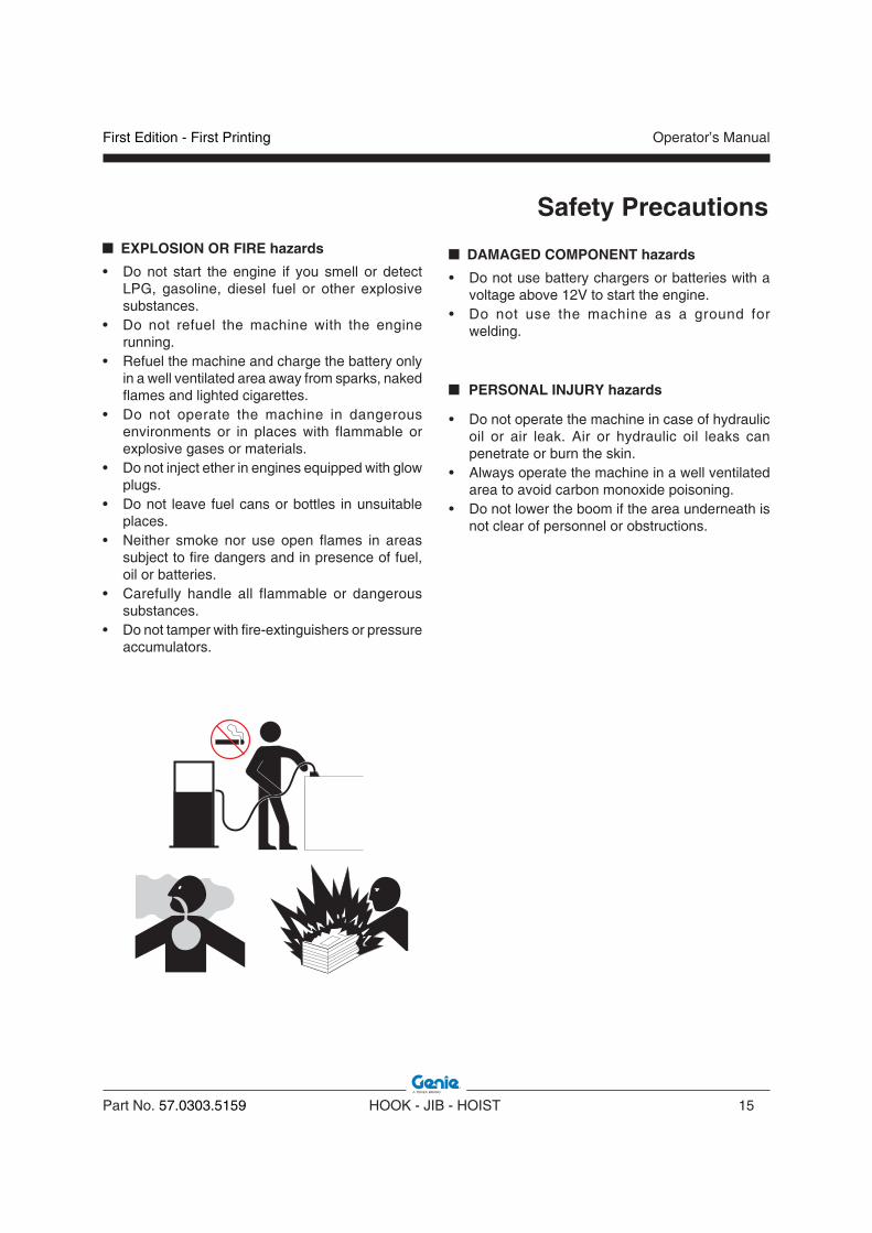
EXPLOSION OR FIRE hazards
• Do not start the engine if you smell or detect LPG, gasoline, diesel fuel or other explosive substances.
• Do not refuel the machine with the engine running.
• Refuel the machine and charge the battery only in a well ventilated area away from sparks, naked flames and lighted cigarettes.
• Do not operate the machine in dangerous environments or in places with flammable or explosive gases or materials.
• Do not inject ether in engines equipped with glow plugs.
• Do not leave fuel cans or bottles in unsuitable places.
• Neither smoke nor use open flames in areas subject to fire dangers and in presence of fuel, oil or batteries.
• Carefully handle all flammable or dangerous substances.
• Do not tamper with fire-extinguishers or pressure accumulators.
Safety Precautions
DAMAGED COMPONENT hazards
• Do not use battery chargers or batteries with a voltage above 12V to start the engine.
• Do not use the machine as a ground for welding.
PERSONAL INJURY hazards
• Do not operate the machine in case of hydraulic oil or air leak. Air or hydraulic oil leaks can penetrate or burn the skin.
• Always operate the machine in a well ventilated area to avoid carbon monoxide poisoning.
• Do not lower the boom if the area underneath is not clear of personnel or obstructions.

Operator’s Manual
16 HOOK - JIB - HOIST Part No. 57.0303.5159
First Edition - First Printing
SUSPENDED LOAD HAZARDS
• A suspended load has a dynamic, and therefore unpredictable, effect on machine stability, so extreme caution should always be exercised when operating with suspended loads.
• Only lift the load when the telehandler is on firm level ground.
• Do not operate the machine while people are under a suspended load.
• All movements of the load must be accomplished at lowest possible speed.
• Do not lift loads when wind speeds exceed 20 mph (32 kmh).
• Level the telehandler before lifting the load.• Use guide ropes or tag lines by qualified
personnel to help control the load and prevent it from swinging.
• Do not attempt to use the telehandler frame-leveling to compensate for a swinging load.
• Never drag the load.• Do not try to move fixed or obstructed loads.• Only lift a load vertically; do not pull a load
horizontally as it could cause excessive swinging of the load.
• When visibility is or could be obstructed, the operator shall use alternative/additional means to safely transport the load.
• Use of additional personnel to direct the operator in his movements as well as surrounding ground traffic.
• Speed shall be limited by any conditions that could cause any unexpected movement of the load, or jeopardize the safe transport of the load.
• The boom shall be fully retracted during travel.• Only travel on solid surfaces.• Start, travel, turn and stop slowly to prevent the
load from becoming unstable or swing.• Do not exceed walking speed.• The load shall be transported as low to the ground
as practical.• Do not use any controls for re-positioning the load
when traveling. Come to a gradual and complete stop before attempting to re-position the load.
Safety Precautions
First Edition - First Printing Operator’s Manual
Part No. 57.0303.5159 HOOK - JIB - HOIST 17
Equipment Description
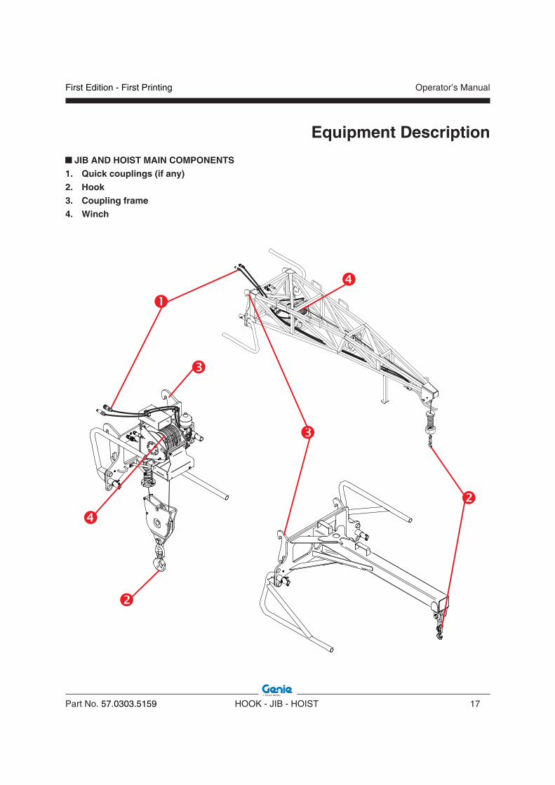
JIB AND HOIST MAIN COMPONENTS1. Quick couplings (if any)2. Hook3. Coupling frame4. Winch

Operator’s Manual
18 HOOK - JIB - HOIST Part No. 57.0303.5159
First Edition - First Printing
Equipment Description
JIB GENERAL DESCRIPTION
This attachment is used to handle payloads which is suspended by a rope system. It mainly consists of a steel truss beams welded structure which is provided with two lateral flanges having mechanical slots (on the upper area) and holes (in the lower area) to be coupled with the GTH telehandlers standard interface. These two lateral flanges are connected together (by welding) through a central steel plate which is then welded to the truss beams structure. The truss beam welded structure is shaped to have, in its forward end, a mechanical link for the connection to a certified steel hook. The hook is certified to handle the payload defined for this attachment (its structural strength meets or exceeds the maximum payload defined for the complete attachment). The hydraulic version of this attachment is provided with an hydraulic hoist installed inside the truss beam structure immediately ahead of the central steel plate. The hoist is hydraulically powered through the auxiliary line provided at the end of the telescopic boom. The hydraulic connection between this line and the hoist is provided through two hydraulic quick coupling adapters. This hoist is equipped with a mechanical drum where a steel rope is winded. The end of the steel rope is linked to the certified hook, placed at the end of the truss beams structure. The rope is guided, between the hoist drum and the hook, by steel pulleys installed inside the truss beam structure and at the end of the truss beams structure. At the end of this structure a special hydraulic switch is installed with the aim to signal when the hook is completely lifted up. When the hook is completely lifted up no hydraulic pressure is provided to the hoist so avoiding any not necessary overload on the jib structural components.
HOIST GENERAL DESCRIPTION
This attachment is used to handle payloads which are suspended by a rope system. It mainly consists of a steel truss beams welded structure which is provided with two lateral flanges having mechanical slots (on the upper area) and holes (in the lower area) to be coupled with the GTH telehandlers standard interface. These two lateral flanges are connected together (by welding) through a central steel plate which is then welded to the truss beams structure. The truss beam welded structure is shaped to have, in its lower end, four supporting feet sustaining the attachment when it is on the ground and not linked to the telehandler. The hydraulic hoist is installed on the front surface of the central steel plate. The hoist is hydraulically powered through the auxiliary line provided at the end of the telescopic boom. The hydraulic connection between this line and the hoist is provided through two hydraulic quick coupling adapters. This hoist is equipped with a mechanical drum where a steel rope is winded. The end of the steel rope is linked directly or through a steel pulley (depending on the model of the attachment) to a certified hook, capable to lift the payload.The hook is certified to handle the payload defined for this attachment (its structural strength meets or exceeds the maximum payload defined for the complete attachment). A special hydraulic switch is installed close to the hook area with the aim to signal when the hook is completely lifted up. When the hook is completely lifted up no hydraulic pressure is provided to the hoist so avoiding any not necessary overload on the jib structural components.

First Edition - First Printing Operator’s Manual
Part No. 57.0303.5159 HOOK - JIB - HOIST 19
Equipment Description
HOOK GENERAL DESCRIPTION
This attachment is used to handle payloads which is suspended by a rope system. It mainly consists of a steel welded structure which is provided with two lateral flanges having mechanical slots (on the upper area) and holes (in the lower area) to be coupled with the GTH telehandlers standard interface. The welded structure is shaped to have, in its central part, a structural beam protruded forward and having at the front end a mechanical link for the connection to a certified steel hook. The hook is certified to handle the payload defined for this attachment (its structural strength meets or exceeds the maximum payload defined for the complete attachment).
HOOK MAIN COMPONENTS
1. Hook2. Coupling frame

Operator’s Manual
20 HOOK - JIB - HOIST Part No. 57.0303.5159
First Edition - First Printing
Equipment Description ALLOWED USE
The hoist and the jib are designed to vertically raise and lower loads by winding and unwinding the cable around the drum.Any other use is considered contrary to what established and, therefore, improper. The compliance with and the strict respect of the use, maintenance and repair instructions of the Manufacturer represent an essential part of the allowed use. The use, maintenance and repair of the equipment shall be carried out by skilled personnel having the necessary knowledge of its special features and the safety precautions to be taken. It is also essential to comply with the national safety at work legislation, the provisions concerning the safety and health of workers at work, and the road traffic regulations.
NOTICEEffecting changes or carrying out interventions on the telehandler and/or on the equipment other than those of routine maintenance is expressly forbidden. Any modification of the telehandler and/or of the equipment not carried out by TEREXLIFT or an authorised assistance centre involves the automatic invalidation of the conformity of the machine.
IMPROPER USE
Improper use means any utilisation of the equipment following working criteria which do not comply with the instructions of this manual, and which, in general, may result in risks for both operator and bystanders .
DANGERWe list below some improper use of the jibs/hoists. Others may exist.- Not strictly complying with the operation and
maintenance instructions of this handbook and of the telehandler handobook;
- Never use the jibs/hoists to lift and/or transport people;
- Working beyond the operation limits of the euipment;
- Working or resting the machine on unstable or yielding grounds;
- Working on steep slopes or working with a nonlevelled telehandler;
- Fit mobile guards that may increase the wind action and jeopardise the stability of the machine;
- Using telescopic handlers not approved or not manufactured by TEREXLIFT in combination with these attachments;
- Attach loads to the boom anywhere other than on the quick coupling frame.

First Edition - First Printing Operator’s Manual
Part No. 57.0303.5159 HOOK - JIB - HOIST 21
EQUIPMENT APPLICATION FIELD
The following table represents the application field of equipment installed on Terexlift telehandlers
Equipment Description
2500kg Fixed Hook on Plate
5000kg Fixed Hook on Plate
4000mm / 900kg
Hydraulic or Mechanical
Jib
2000mm / 2000kg
Jib3000 kg Hoist
GTH-2506
GTH-3007
GTH-4013SXGTH-4017SX
GTH-4013EXGTH-4017EX
GTH-4016SRGTH-4018SR

Operator’s Manual
22 HOOK - JIB - HOIST Part No. 57.0303.5159
First Edition - First Printing
Intentionally blank page

First Edition - First Printing Operator’s Manual
Part No. 57.0303.5159 HOOK - JIB - HOIST 23
Inspections
Make sure:You learn and practice the principles of safe
machine operation contained in this operator's manual and in the telehandler one.
1. Avoid hazardous situations.
2. Always perform a pre-operation inspection.
Know and understand the pre-operation inspection before going on to the next section.
3. Always perform function tests prior to use.
4. Inspect the workplace.
5. Only use the telehandler and the equipment as they were intended.
Pre-operation Inspection FundamentalsIt is the responsibility of the operator to perform a pre-operation inspection and routine maintenance.
The pre-operation inspection is a visual inspection performed by the operator prior to each work shift. The inspection is designed to discover if anything is apparently wrong with a telehandler and/or with an equipment before the operator performs the function tests.
The pre-operation inspection also serves to determine if routine maintenance procedures are required. Only routine maintenance items specified in this manual may be performed by the operator.
If damage or any unauthorized variation from factory delivered condition is discovered, the telehandler and/or the equipment must be tagged and removed from service.
Repairs to the telehandler and/or the equipment may only be made by a qualified service technician, according to the manufacturer's specifications. After repairs are completed, the operator must perform a pre-operation inspection again before going on to the function tests.
Scheduled maintenance inspections shall be performed by qualified service technicians, according to the manufacturer's specifications.
Operator’s Manual
24 HOOK - JIB - HOIST Part No. 57.0303.5159
First Edition - First Printing
Inspections PRE-OPERATION INSPECTION
For the Maintenance and the Pre-operation Inspection of the telehandler, refer to the specific Operator's Manual presents placed inside the cabin.
For the equipment:• Make sure the operator’s manuals are intact,
legible and placed inside the telehandler.• Make sure all decals are present and legible. See
“Labels And Plates Applied” chapter.• Check for hydraulic oil leaks and proper oil level.
Top up if necessary. See “Maintenance” chapter.
Check the following components or zones for damage, missing or wrongly fitted parts or non-authorised modifications:
• electrical components and electrical cables• hydraulic hoses and fittings• fuel and hydraulic oil tanks• nuts, bolts and other fasteners
Check the entire structure for: • cracks on welds or structural components • dents or damage to the structure
WARNINGIf even one single item is damaged or modified, do not start work. Stop the machine and repair the fault.
NOTICE If the machine shall be used in a marine or equivalent environment, protect it against salt deposits with an adequate treatment against saltiness to prevent rust formation.

First Edition - First Printing Operator’s Manual
Part No. 57.0303.5159 HOOK - JIB - HOIST 25
Inspections
TESTSAbout the telehandler:1. Select a test area that is firm, level and free of
obstruction.
2. Enter the operator's compartment and sit on the seat.
3. Fasten the seat belt.
4. Adjust all the mirrors.
5. Be sure the parking brake is on and the transmission control is in neutral.
6. Start the engine.
Perform all the tests provided for the telehandler and listed in the machine Operator's Manual.
Test the Control Lever
7. Using the control lever, momentarily raise and lower the rope.
Result: All functions should operate smoothly.
FUNCTION TESTS FUNDAMENTALS
The function tests are designed to discover any malfunctions before the machine is put into service. The operator must follow the step-by-step instructions to test all machine functions. A malfunctioning machine must never be used. If malfunctions are discovered, the machine must be tagged and removed from service. Repairs to the machine may only be made by a qualified service technician, according to the manufacturer's specifications. After repairs are completed, the operator must perform a pre-operation inspection and function tests again before putting the machine into service.
Make sure:You learn and practice the principles of safe
machine operation contained in this operator's manual and in the telehandler one.
1. Avoid hazardous situations.
2. Always perform a pre-operation inspection.
Know and understand the pre-operation inspection before going on to the next section.
3. Always perform function tests prior to use.
4. Inspect the workplace.
5. Only use the telehandler and the equipment as they were intended.

Operator’s Manual
26 HOOK - JIB - HOIST Part No. 57.0303.5159
First Edition - First Printing
WORKPLACE INSPECTION
The workplace inspection helps the operator determine if the workplace is suitable for safe machine operation. It should be performed by the operator prior to moving the machine to the workplace.
It is the operator's responsibility to read and remember the workplace hazards, then watch for and avoid them while moving, setting up and operating the machine
Be aware of and avoid the following hazardous situations:
• drop-offs or holes
• bumps, floor obstructions or debris
• sloped surfaces
• unstable or slippery surfaces
• overhead obstructions and high voltage conductors
• hazardous locations
• inadequate surface support to withstand all load forces imposed by the machine
• wind and weather conditions
• the presence of unauthorized personnel
• other possible unsafe conditions
Inspections
First Edition - First Printing Operator’s Manual
Part No. 57.0303.5159 HOOK - JIB - HOIST 27
Operating Instructions
This section provides the operator and the ground staff a practical guide for the gradual learning of the use of the telehandler fitted with either a hook, jib or hoist.Both operator and ground staff shall have all the necessary requisites and shall become familiar with both telehandler and equipment before starting using them.This familiarisation ensures a proper use during work.
WARNINGBefore using the telehandler, inspect the job site and check for possible hazardous conditions. Make sure that there are no holes, moving banks or debris that may cause you to lose the control of the machine.
DANGERPay the greatest attention when working close to electric lines. Check their position and ensure that no part of the machine operates at less than 6 meters from the power lines.
WARNINGFor a safe use of the telehandler with equipment, before elevating any load, always know the weight of the loads going to be handled.
Operator’s Manual
28 HOOK - JIB - HOIST Part No. 57.0303.5159
First Edition - First Printing
Operating Instructions
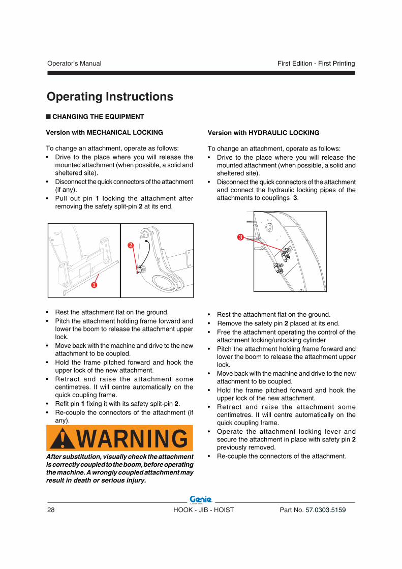
CHANGING THE EQUIPMENT
Version with MECHANICAL LOCKING
To change an attachment, operate as follows:• Drive to the place where you will release the
mounted attachment (when possible, a solid and sheltered site).
• Disconnect the quick connectors of the attachment (if any).
• Pull out pin 1 locking the attachment after removing the safety split-pin 2 at its end.
• Rest the attachment flat on the ground.• Pitch the attachment holding frame forward and
lower the boom to release the attachment upper lock.
• Move back with the machine and drive to the new attachment to be coupled.
• Hold the frame pitched forward and hook the upper lock of the new attachment.
• Retract and raise the attachment some centimetres. It will centre automatically on the quick coupling frame.
• Refit pin 1 fixing it with its safety split-pin 2.• Re-couple the connectors of the attachment (if
any).
WARNINGAfter substitution, visually check the attachment is correctly coupled to the boom, before operating the machine. A wrongly coupled attachment may result in death or serious injury.
Version with HYDRAULIC LOCKING
To change an attachment, operate as follows:• Drive to the place where you will release the
mounted attachment (when possible, a solid and sheltered site).
• Disconnect the quick connectors of the attachment and connect the hydraulic locking pipes of the attachments to couplings 3.
• Rest the attachment flat on the ground.• Remove the safety pin 2 placed at its end.• Free the attachment operating the control of the
attachment locking/unlocking cylinder• Pitch the attachment holding frame forward and
lower the boom to release the attachment upper lock.
• Move back with the machine and drive to the new attachment to be coupled.
• Hold the frame pitched forward and hook the upper lock of the new attachment.
• Retract and raise the attachment some centimetres. It will centre automatically on the quick coupling frame.
• Operate the attachment locking lever and secure the attachment in place with safety pin 2 previously removed.
• Re-couple the connectors of the attachment.
First Edition - First Printing Operator’s Manual
Part No. 57.0303.5159 HOOK - JIB - HOIST 29
Operating Instructions
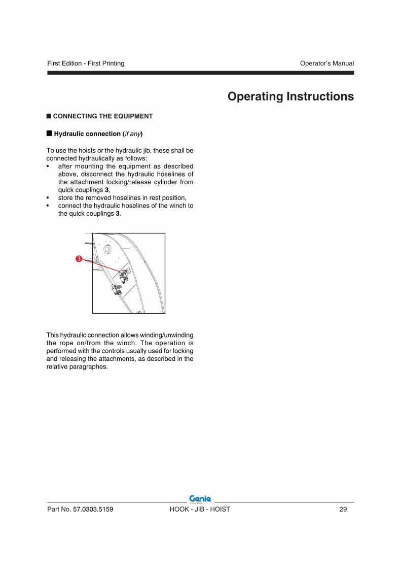
CONNECTING THE EQUIPMENT
n Hydraulic connection (if any)
To use the hoists or the hydraulic jib, these shall be connected hydraulically as follows:• after mounting the equipment as described
above, disconnect the hydraulic hoselines of the attachment locking/release cylinder from quick couplings 3,
• store the removed hoselines in rest position, • connect the hydraulic hoselines of the winch to
the quick couplings 3.
This hydraulic connection allows winding/unwinding the rope on/from the winch. The operation is performed with the controls usually used for locking and releasing the attachments, as described in the relative paragraphes.

Operator’s Manual
30 HOOK - JIB - HOIST Part No. 57.0303.5159
First Edition - First Printing
Operating Instructions STABILITY CONTROL SYSTEM
All the telehandlers are equipped with an automatic stability control system which warns the operator of the variation of stability of the machine and blocks any manoeuvre before the same reaches a critical condition. A display inside the cabin shows the stability status of the machine and the relative equipment.
LLMI/ LLMC HAZARDSThe LLMI/LLMC will only function to the design specification:• when the truck is static;• when the truck is on consolidated, stable and
level ground;• when the truck is performing loading or placing
functions;• when the LLMI/LLMC is activated (not
overridden);
The LLMI will only warn the operator in the event of inadequate stability in the longitudinal plane in the forward direction.The LLMI/LLMC is not intended for warning of the risk of overturning in the case of:• a sudden overload;• travelling with the load in the elevated position;• travelling on rough terrain or on grounds with
obstacles and holes;• travelling across a slope or turning on a slope;• driving in bends too fast or too sharp;Adjustments affecting the setting of the LLMI/LLMC shall be performed only by authorised personnel.
The system changes according with the telehandler and can easly be recognized depending on the display fitted into the cabin:
MODEL N°1
1. Used only for calibration2. Stability indicator with LED-bar3. Green light - power OK4. Used for calibration. On machine models
provided with outriggers it lights up when the outriggers are lowered.
5. Used only for calibration
OperationWhen power is turned on, light 3, the led bar 2 and button 4 and 5 come on. The monitoring system runs a self-test.During operation, the LED-bar 2 lights up gradually depending on the variation of stability.
L1
L2
L3
L4
L5
L6
LED Bar
First Edition - First Printing Operator’s Manual
Part No. 57.0303.5159 HOOK - JIB - HOIST 31
Operating Instructions
MODEL N°2
ENTER
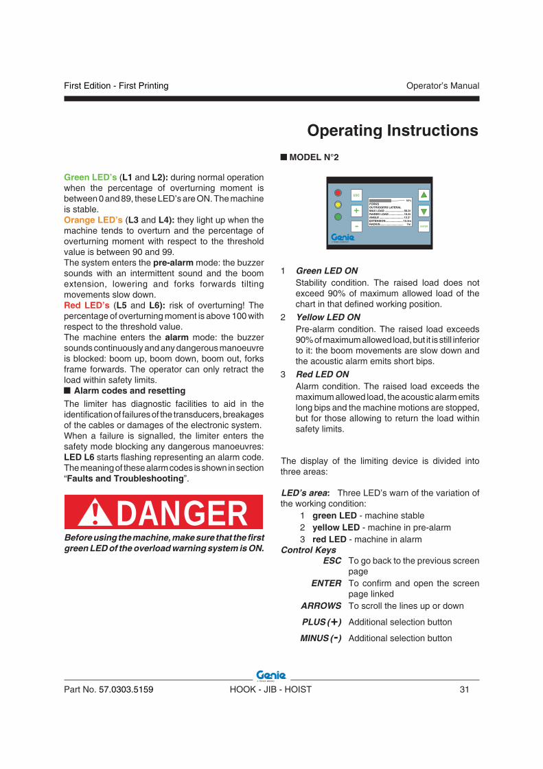
FORKSOUTRIGGERS LATERALMAX LOAD ........................ 50.3tRAISED LOAD................... 10.2tANGLE ............................... 12.3°EXTENSION...................... 12.3mRADIUS.............................. 7m
55%
ESC
+
-
1 Green LED ON Stability condition. The raised load does not
exceed 90% of maximum allowed load of the chart in that defined working position.
2 Yellow LED ON Pre-alarm condition. The raised load exceeds
90% of maximum allowed load, but it is still inferior to it: the boom movements are slow down and the acoustic alarm emits short bips.
3 Red LED ON Alarm condition. The raised load exceeds the
maximum allowed load, the acoustic alarm emits long bips and the machine motions are stopped, but for those allowing to return the load within safety limits.
The display of the limiting device is divided into three areas:
LED’s area: Three LED’s warn of the variation of the working condition: 1 green LED - machine stable 2 yellow LED - machine in pre-alarm 3 red LED - machine in alarmControl Keys ESC To go back to the previous screen
page ENTER To confirm and open the screen
page linked ARROWS To scroll the lines up or down
PLUS (+) Additional selection button
MINUS (-) Additional selection button
Green LED’s (L1 and L2): during normal operation when the percentage of overturning moment is between 0 and 89, these LED’s are ON. The machine is stable.Orange LED’s (L3 and L4): they light up when the machine tends to overturn and the percentage of overturning moment with respect to the threshold value is between 90 and 99. The system enters the pre-alarm mode: the buzzer sounds with an intermittent sound and the boom extension, lowering and forks forwards tilting movements slow down.Red LED’s (L5 and L6): risk of overturning! The percentage of overturning moment is above 100 with respect to the threshold value. The machine enters the alarm mode: the buzzer sounds continuously and any dangerous manoeuvre is blocked: boom up, boom down, boom out, forks frame forwards. The operator can only retract the load within safety limits.
Alarm codes and resettingThe limiter has diagnostic facilities to aid in the identification of failures of the transducers, breakages of the cables or damages of the electronic system.When a failure is signalled, the limiter enters the safety mode blocking any dangerous manoeuvres: LED L6 starts flashing representing an alarm code.The meaning of these alarm codes is shown in section “Faults and Troubleshooting”.
DANGERBefore using the machine, make sure that the first green LED of the overload warning system is ON.

Operator’s Manual
32 HOOK - JIB - HOIST Part No. 57.0303.5159
First Edition - First Printing
FORKSOUTRIGGERS LATERALMAX LOAD ........................ 50.3tRAISED LOAD................... 10.2tANGLE ............................... 12.3°EXTENSION...................... 12.3mRADIUS.............................. 7m
55%������
fig. Afig. A
Display, which is divided into 8 lines_ fig.A 1. Load percentage strip 2. Indicates the attachment used3. Indicates the operating mode4. Indicates the max. load that can be raised5. Indicates the weight raised for the system
calibration6. Indicates the boom angle 7. Indicates the boom extension (it’ll be = 0
meters once the boom is fully retracted)8. Indicates the distance of the load from the
slewring axis and, in case of necessity, it displays the related warning message
Operation• At the machine starting, the overload warning
system runs an automatic check and the software datas are displayed.
• Within 3/4 seconds, the list of attachments allowed is displayed: using the arrows, the operator has to select the right attchment and then press ENTER to confirm.
• Once the attachment has been selected, the display shows the Standard Screen Page (fig.A).
• From this screen page, pushing PLUS (+) for some seconds, the operator can open the UPPER LEVEL (B) where other four sub-menus are displayed: one of these, LANGUAGE (C) can be modified while the other three, CLOCK (D), EXTENTION SENSOR (E) and ANGLE SENSOR (F), can only be consulted.
• Pressing ESC, go back to the Standard Screen Page.
Operating Instructions
• Press the two buttons PLUS (+) and MINUS
(-) simultaneously to access to the Diagnostic Screen Pages. These pages can only be consulted. Use the ARROWS to pass from one page to another.
LANGUAGEEXTENSION SENSOR
ANGLE SENSOR
CLOCK
ITALIANO
FRANÇAIS
ESPAÑOL
ENGLISH15:25:4210/01/09
LANGUAGEEXTENSION SENSOR
ANGLE SENSOR
CLOCK
� �
�
MIN1 20
EXIT
MIN2 20MAX1 1000 MAX2 1000
N1 915 N2 913
LANGUAGEEXTENSION SENSOR
ANGLE SENSOR
CLOCK
EXIT
ZERO1 511 ZERO2 511
N1 552 N2 551
LANGUAGEEXTENSION SENSOR
ANGLE SENSOR
CLOCK
� �
� �
DANGERBefore using the machine, make sure that the green LED is ON, and that the operating mode shown in line 3 and the attachment shown in line 2 are those actually used.
First Edition - First Printing Operator’s Manual
Part No. 57.0303.5159 HOOK - JIB - HOIST 33
Operating Instructions
A B C D E
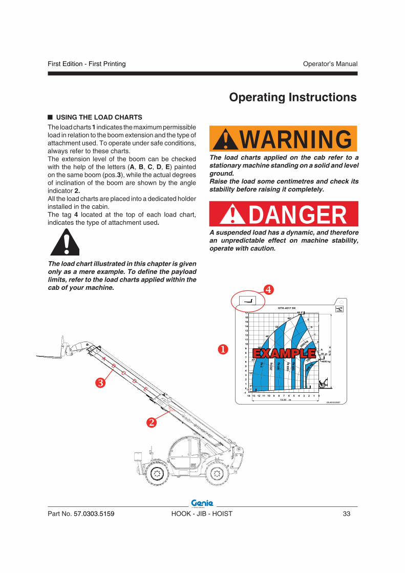
USING THE LOAD CHARTSThe load charts 1 indicates the maximum permissible load in relation to the boom extension and the type of attachment used. To operate under safe conditions, always refer to these charts. The extension level of the boom can be checked with the help of the letters (A, B, C, D, E) painted on the same boom (pos.3), while the actual degrees of inclination of the boom are shown by the angle indicator 2.All the load charts are placed into a dedicated holder installed in the cabin. The tag 4 located at the top of each load chart, indicates the type of attachment used.
The load chart illustrated in this chapter is given only as a mere example. To define the payload limits, refer to the load charts applied within the cab of your machine.
WARNINGThe load charts applied on the cab refer to a stationary machine standing on a solid and level ground. Raise the load some centimetres and check its stability before raising it completely.
DANGERA suspended load has a dynamic, and therefore an unpredictable effect on machine stability, operate with caution.
09.4618.0937
GTH-4017 SX
EXAMPLEEXAMPLE

Operator’s Manual
34 HOOK - JIB - HOIST Part No. 57.0303.5159
First Edition - First Printing
Lifting a load with the centre of gravity offset will cause the load to shift until a balance is restored. If there is the slightest doubt of the stability of a load, it should be slowly lifted just clear of the ground. If the load tilts, the sling should be refixed in a more stable position.
LOAD SECURITY Before lifting it is essential to ensure that, when clear of the ground, the load will adopt the intended attitude and remain securely attached to the lifting appliance without overloading any of the lifting gear. This means that the load must be both balanced andstable.
BALANCEIn the majority of lifts it will be intended that the load will remain level when clear of the ground. To achieve this it is first necessary to position the hook of the lifting appliance vertically above the centre of gravity of the load.The legs of the sling(s) should be distributed as evenly as is practicable according to the lifting points available. The angle which the individual leg makes with the vertical, affects the proportion of the load which will be imposed upon it and all legs should therefore be, so far as is practicable, at a similar angle to provide equal loading.If the load tilts on lifting, the load in the sling legs will become unequal. This effect is especially significant at small included angles between sling legs.With rigid loads when three or more legs are employed, consideration should be given to how many of the legs will bear the weight as it may be found that only two or three will take the majority with the remaining legs providing a relatively small‘balancing force’ only. If this is the case, larger capacity tackle will be required.
STABILITYIn this context, stability means ‘resistance to toppling’. An object with a narrow base and a high centre of gravity will need less force to topple it than one with a wide base and a low centre of gravity.As the height of the centre of gravity increases relative
Operating Instructions
SLINGING LOAD
EVALUATING THE LOADThe operator should take all practicable steps to establish the weight and the position of its centre of gravity of any load. A drawing may be available giving the weight or it may be calculable within reasonable limits of accuracy. The following gives guidance as to the various ways of obtaining this information.
WARNINGVerify that the load to be lifted respects the max payload of the equipment and of the telehandler. Refer to the relative Load Chart. WEIGHT1. Look to see if the weight is marked on the load.
If it is, check to ensure that it is the weight of all parts of the load;
2. Check the weight stated on any documentation.3. Look at the drawing of the load. If the weight
is marked, check as in (1) above to ensure it includes all parts of the load.
4. Estimate the weight of the load by using tables of material weights, as, for example, the ones shown in the "Tables of Material" section.
CENTRE OF GRAVITYThe “centre of gravity” (CoG) is a point which, if the load could be suspended from the hook, the load would be in perfect balance.The hook needs to be directly over the centre of gravity, for the load to be stable, as shown in fi g.A.
Fig.A

First Edition - First Printing Operator’s Manual
Part No. 57.0303.5159 HOOK - JIB - HOIST 35
Operating Instructions
to the width of the base, a point will be reached where the object will fall over unless it is supported by external means. At this point the object is regarded as being unstable and the greater the support required themore unstable it is.A similar situation exists with a suspended load. Forces which try to topple the load will inevitably be present (e.g. wind, acceleration, braking). It is essential, therefore, when slinging a load, to ensurethat it is sufficiently stable to resist these toppling forces.A load will be inherently stable if the lifting tackle is attached ABOVE the centre of gravity and properly positioned around it.
HARNESSING ACCESSORIESA good packing between sling and load is fondamental. Operate as follow:• Check the load: dimensions, weight and units• Select the right sling for each job using the
manufacturers' tables • Inspect each item of lifting equipment before
and after lifts• Protect slings from damage by sharp edges with
corner saddles, padding, or wooden blocks
• When lifting long loads, particularly in confined spaces, slingers should attach a rope or ‘tag line’ to one or both ends of the load so that rotational movement may be controlled.
• Hook unused sling legs to the sling ring.
WARNING• Protect your hands and fingers: when slack
is being taken out of a sling, keep them from between the sling and load so they will not be trapped and crushed. Step away before the lift is made.
• Avoid impact loading: do not jerk the load when lifting or lowering the sling. This increases the actual stress on the sling.
• Do not exceed the capacities of slings• Do not twist or tie knots in slings or use bolts,
nails or pieces of wire to shorten slings. • Do not splice together broken slings. • Do not carry a load by inserting the point of
the hook into a link of the chain.• Do not leave unused slings, accessories, or
blocking lying on the floor. Hang on racks or store in a proper place.
• Do not use a sling to drag a load. • Do not shorten a chain with knots or by
twisting other than by means of an integral chain clutch.
• Do not use homemade chains or strings. • Do not heat treat or weld chain links: the
lifting capacity will be reduced drastically. • Do not expose chain links to chemicals
without the manufacturers approval.
WARNINGHooks are designed to support the load in the bowl A. Users should ensure that the hook of a sling engages freely in the lifting point so that the weight of the load is supported in the bowl of the hook.Wedging or forcing the hook tip B into the lifting points results in the hook being stressed in a manner for which it was not designed which may easily lead to hook deformation and premature failure.
�
�

Operator’s Manual
36 HOOK - JIB - HOIST Part No. 57.0303.5159
First Edition - First Printing
Operating Instructions
CONTROLS
n GTH-2506 and GTH-3007 controls
DANGERBefore operating the winch, make sure that nobody is within its working range.
To lower/recover the winch rope:
• set the control lever to central position,
• press button ,
• shift the control lever to position to lower the rope,
• shift the control lever to position � to recover the rope.
1
WARNINGAs the raising and lowering speed of the winch is determined by the fl ow of the oil, it is recommended to move the control lever gently when you perform raising and lowering manoeuvers so as to avoid violent joilts of the load which would provoke strains on all the structural elements and could result in the machine becoming unstable.

First Edition - First Printing Operator’s Manual
Part No. 57.0303.5159 HOOK - JIB - HOIST 37
Operating Instructions
n GTH-4013SX and GTH-4017SX controls
DANGERBefore operating the winch, make sure that nobody is within its working range.
To lower/recover the winch rope:
• set the lever � to central position,
• shift the lever to position to lower the rope,
• shift the lever to position � to recover the rope.
�
WARNINGAs the raising and lowering speed of the winch is determined by the fl ow of the oil, it is recommended to move the control lever gently when you perform raising and lowering manoeuvers so as to avoid violent joilts of the load which would provoke strains on all the structural elements and could result in the machine becoming unstable.
Operator’s Manual
38 HOOK - JIB - HOIST Part No. 57.0303.5159
First Edition - First Printing
Operating Instructions
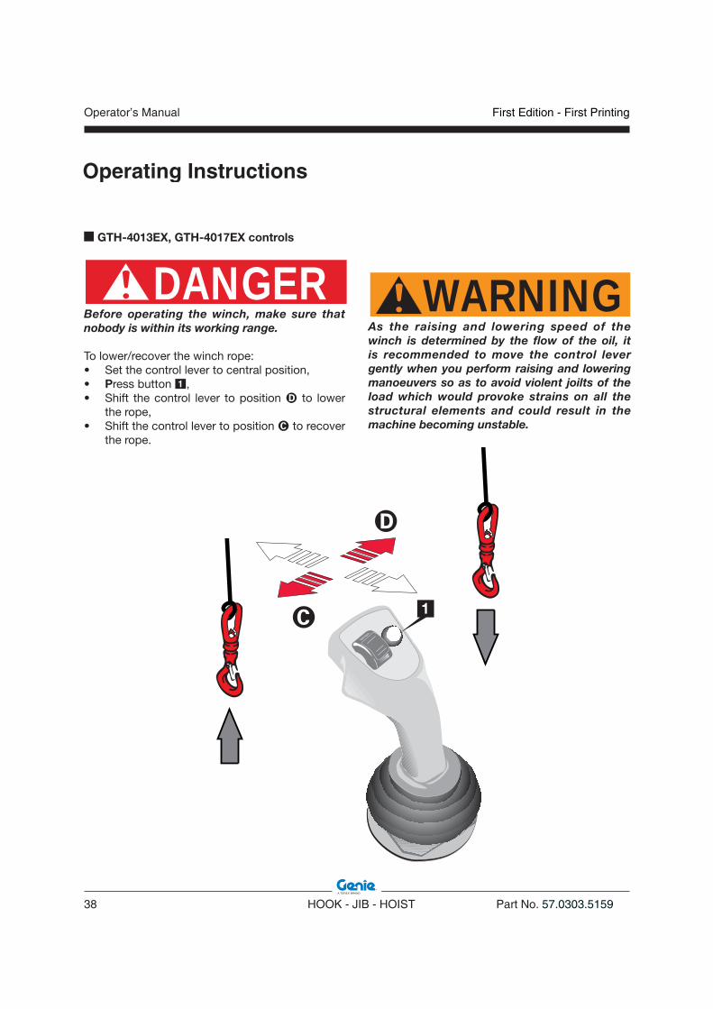
n GTH-4013EX, GTH-4017EX controls
DANGERBefore operating the winch, make sure that nobody is within its working range.
To lower/recover the winch rope:• Set the control lever to central position,• Press button ,• Shift the control lever to position to lower
the rope,• Shift the control lever to position � to recover
the rope.
1
WARNINGAs the raising and lowering speed of the winch is determined by the fl ow of the oil, it is recommended to move the control lever gently when you perform raising and lowering manoeuvers so as to avoid violent joilts of the load which would provoke strains on all the structural elements and could result in the machine becoming unstable.

First Edition - First Printing Operator’s Manual
Part No. 57.0303.5159 HOOK - JIB - HOIST 39
Operating Instructions
n GTH-4016SR and GTH-4018SR controls
DANGERBefore operating the winch, make sure that nobody is within its working range.
To lower/recover the winch rope:WITH LEFT JOYSTICK (Optional Configuration)• Set the control lever to central position and
press switch �.• Smoothly shift the lever to position � to lower
the rope.• Shift the lever to position � to recover the rope.
OPTIONAL CONFIGURATIONSTANDARD CONFIGURATION
WITH RIGHT JOYSTICK (Standard Configuration)• Set the control lever to central position and press
switch �.• Press button � and hold it pressed until the end
of the motion.• Smoothly shift the lever to position � to lower
the rope.• Shift the lever to position to recover the rope.
WARNINGAs the raising and lowering speed of the winch is determined by the fl ow of the oil, it is recommended to move the control lever gently when you perform raising and lowering manoeuvers so as to avoid violent joilts of the load which would provoke strains on all the structural elements and could result in the machine becoming unstable.
Operator’s Manual
40 HOOK - JIB - HOIST Part No. 57.0303.5159
First Edition - First Printing
Operating Instructions OPERATION
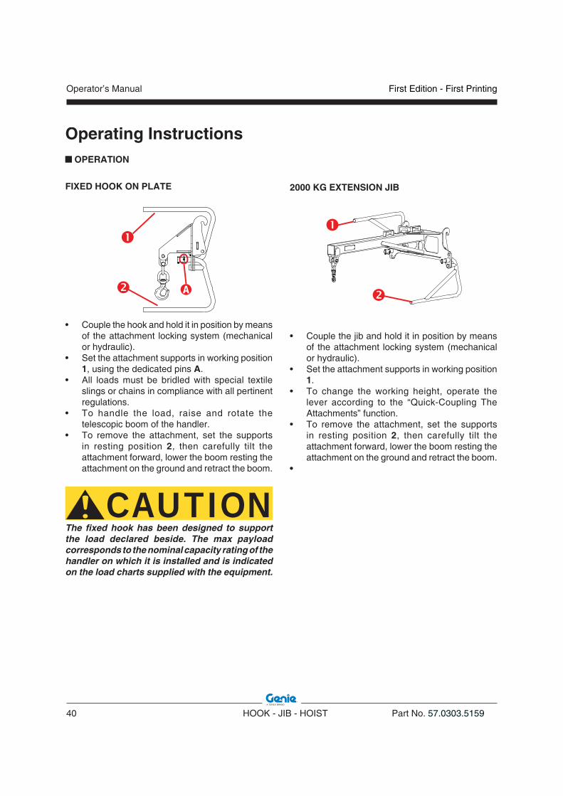
FIXED HOOK ON PLATE
�
• Couple the hook and hold it in position by means of the attachment locking system (mechanical or hydraulic).
• Set the attachment supports in working position 1, using the dedicated pins A.
• All loads must be bridled with special textile slings or chains in compliance with all pertinent regulations.
• To handle the load, raise and rotate the telescopic boom of the handler.
• To remove the attachment, set the supports in resting position 2, then carefully tilt the attachment forward, lower the boom resting the attachment on the ground and retract the boom.
CAUTIONThe fixed hook has been designed to support the load declared beside. The max payload corresponds to the nominal capacity rating of the handler on which it is installed and is indicated on the load charts supplied with the equipment.
2000 KG EXTENSION JIB
• Couple the jib and hold it in position by means of the attachment locking system (mechanical or hydraulic).
• Set the attachment supports in working position 1.
• To change the working height, operate the lever according to the “Quick-Coupling The Attachments” function.
• To remove the attachment, set the supports in resting position 2, then carefully tilt the attachment forward, lower the boom resting the attachment on the ground and retract the boom.
•
First Edition - First Printing Operator’s Manual
Part No. 57.0303.5159 HOOK - JIB - HOIST 41
Operating Instructions
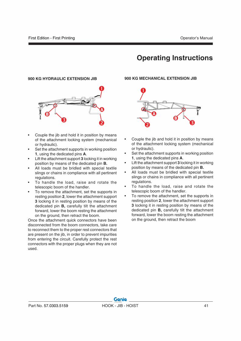
900 KG HYDRAULIC EXTENSION JIB
�
�
• Couple the jib and hold it in position by means of the attachment locking system (mechanical or hydraulic).
• Set the attachment supports in working position 1, using the dedicated pins A.
• Lift the attachment support 3 locking it in working position by means of the dedicated pin B.
• All loads must be bridled with special textile slings or chains in compliance with all pertinent regulations.
• To handle the load, raise and rotate the telescopic boom of the handler.
• To remove the attachment, set the supports in resting position 2, lower the attachment support 3 locking it in resting position by means of the dedicated pin B, carefully tilt the attachment forward, lower the boom resting the attachment on the ground, then retract the boom.
Once the attachment quick connectors have been disconnected from the boom connectors, take care to reconnect them to the proper rest connectors that are present on the jib, in order to prevent impurities from entering the circuit. Carefully protect the rest connectors with the proper plugs when they are not used.
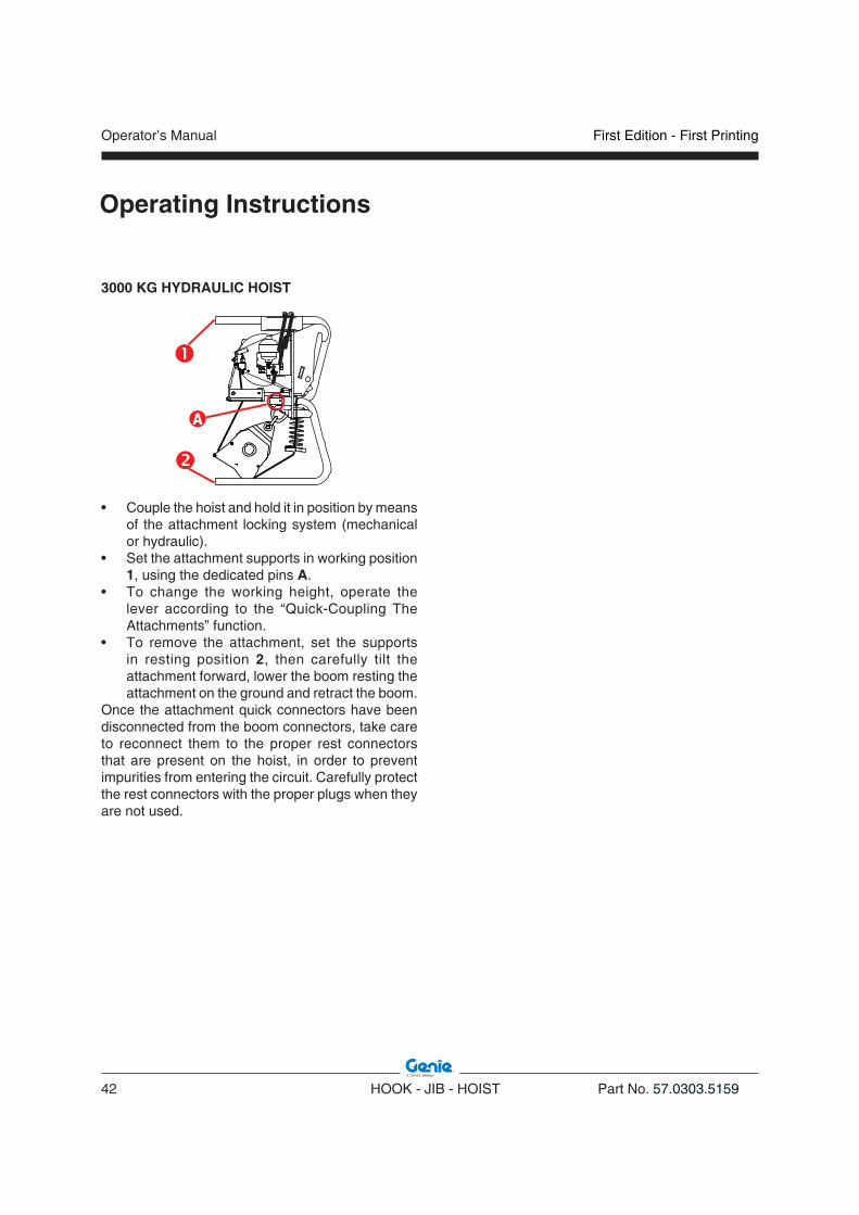
900 KG MECHANICAL EXTENSION JIB
�
�
• Couple the jib and hold it in position by means of the attachment locking system (mechanical or hydraulic).
• Set the attachment supports in working position 1, using the dedicated pins A.
• Lift the attachment support 3 locking it in working position by means of the dedicated pin B.
• All loads must be bridled with special textile slings or chains in compliance with all pertinent regulations.
• To handle the load, raise and rotate the telescopic boom of the handler.
• To remove the attachment, set the supports in resting position 2, lower the attachment support 3 locking it in resting position by means of the dedicated pin B, carefully tilt the attachment forward, lower the boom resting the attachment on the ground, then retract the boom
Operator’s Manual
42 HOOK - JIB - HOIST Part No. 57.0303.5159
First Edition - First Printing
Operating Instructions
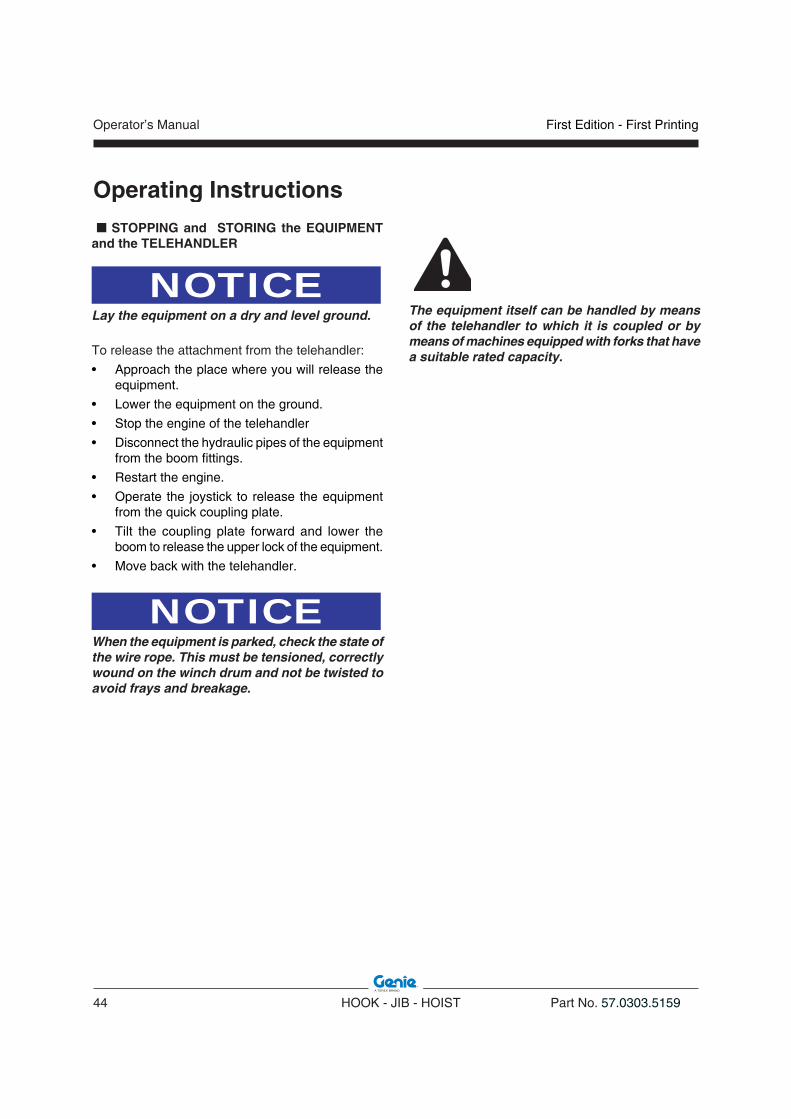
3000 KG HYDRAULIC HOIST
�
• Couple the hoist and hold it in position by means of the attachment locking system (mechanical or hydraulic).
• Set the attachment supports in working position 1, using the dedicated pins A.
• To change the working height, operate the lever according to the “Quick-Coupling The Attachments” function.
• To remove the attachment, set the supports in resting position 2, then carefully tilt the attachment forward, lower the boom resting the attachment on the ground and retract the boom.
Once the attachment quick connectors have been disconnected from the boom connectors, take care to reconnect them to the proper rest connectors that are present on the hoist, in order to prevent impurities from entering the circuit. Carefully protect the rest connectors with the proper plugs when they are not used.

First Edition - First Printing Operator’s Manual
Part No. 57.0303.5159 HOOK - JIB - HOIST 43
LOAD LANDING
Before a load is lifted, a place should be prepared where it is to be put down. The nature of the load will determine the type of preparation necessary but most loads should be lowered onto timber battens. The sling may then be easily withdrawn. The load should never be landed directly on to the chain.
Operating Instructions
TRANSPORTING A SUSPENDED LOADOnce the load is attached, operate as follow:• raise the load and check if it is correctly
suspended: the wire shall be tightened and shall not be in slack-condition when the load movement begins;
• completly retract the boom;• raise it again to the transport height of 300-500mm
from the ground;• make sure a load is high enough to clear all
objects before starting to move;• identify any risks present on the route to be
travelled;• avoid excessively undulating ground when
travelling;• consider that when transporting load permissible
gradients are 10% downhill, 15% uphill, 5% side;• consider effects of the wind on load: wind speed
should not exceed 10m/s or number 5 of the Beaufort Scale, as explain in the "Beaufort Wind Scale" section;
• initiate movements of the load with the lowest available speed;
• travel at walking speed (1,5 km/h).
DANGER• Do not allow suspended loads to oscillate.• Do not drag loads when they are hooked up.• Do not ride on hooks or loads. • Do not allow workers to walk or work under
a load. • Do not leave suspended loads unattended.• Warn all people out of the load area before
starting the lift.
WARNINGWhen visibility is or could be obstructed, the operator shall use alternative/additional means to safely transport the load: use of additional personnel to direct the operator in his movements as well as surrounding ground traffic.
Operator’s Manual
44 HOOK - JIB - HOIST Part No. 57.0303.5159
First Edition - First Printing
Operating Instructions STOPPING and STORING the EQUIPMENT and the TELEHANDLER
NOTICELay the equipment on a dry and level ground.
To release the attachment from the telehandler:
• Approach the place where you will release the equipment.
• Lower the equipment on the ground.
• Stop the engine of the telehandler
• Disconnect the hydraulic pipes of the equipment from the boom fittings.
• Restart the engine.
• Operate the joystick to release the equipment from the quick coupling plate.
• Tilt the coupling plate forward and lower the boom to release the upper lock of the equipment.
• Move back with the telehandler.
NOTICEWhen the equipment is parked, check the state of the wire rope. This must be tensioned, correctly wound on the winch drum and not be twisted to avoid frays and breakage.
The equipment itself can be handled by means of the telehandler to which it is coupled or by means of machines equipped with forks that have a suitable rated capacity.

First Edition - First Printing Operator’s Manual
Part No. 57.0303.5159 HOOK - JIB - HOIST 45
Operating Instructions
n Moving the Equipment
CAUTIONWhen the equipment shall be moved, use only means having a suitable capacity. The characteristic data are detailed in the relevant chapter of this manual and on the identification plate.According to the equipment, proceed as follow for moving:
• 900kg JIB, insert the forks into the four dedicated lugs 1
• 2000kg JIB, insert the forks into the two dedicated lugs 2
• HOIST, insert the forks into the dedicated lug 3
• HOOK, run two slings through the frame holes as shown in the draft below

Operator’s Manual
46 HOOK - JIB - HOIST Part No. 57.0303.5159
First Edition - First Printing
Operating Instructions
n Parking for Short PeriodsAlways park the telehandler in a safe way after a working day, a shift and at night.Take all precautions to prevent damage to those persons who will approach the machine while stationary:• Park the machine so that it does not hinder other
operations.
• Put the parking brake.
• Remove the key from the ignition switch and lock the cab door.
Parking for Long PeriodsIn case of extended inactivity of the telehandler and/or the equipment, follow the above precautions and additionally:• Wash the machine thoroughly. For a better
cleaning, remove grills and protection casings.
CAUTIONDo not use gasoline, solvents or other flammable products for cleaning purposes. Use only authorized, non-flammable and harmless solvents. Wear safety goggles and a protection mask when you use compressed air. In case of washing, do not direct the jet of water towards electrical parts.
• Carefully dry all machine parts by blowing some compressed air.
• Lubricate the machine thoroughly.• Do a walk-around inspection and replace any
worn or damaged part.• Re-paint any worn or damaged part.• Store the machine in a sheltered and well-
ventilated place.
WARNINGAlways remember that the ordinary maintenance must be carried out even during the machine inactivity. Pay particular attention to the fluid levels and to those parts subject to ageing. Before re-starting the machine and the equipment, carry out an extraordinary maintenance and carefully check all mechanical, hydraulic and electrical components.
DISPOSAL
PROTECT THEENVIRONMENT
At the end of the telehandler and/or the equipment life, call in a specialised firm to dispose of it in compliance with the local or national regulations.
BATTERY DISPOSAL
PROTECT THEENVIRONMENT
Used lead-acid batteries cannot be disposed of as normal industrial solid wastes. Because of the presence of harmful substances, they must be collected, eliminated and/or recycled in accordance with the laws of the UE.Used batteries must be kept in a dry and confined place. Make sure the battery is dry and the cell plugs are tight. Place a sign on the battery to warn of not using it. If before disposal the battery is left in the open air, it will be necessary to dry, smear the box and the elements with a coat of grease and tighten the plugs. Do not rest the battery on the ground; it is always advisable to rest it on a pallet and cover it. The disposal of batteries shall be as rapid as possible.
First Edition - First Printing Operator’s Manual
Part No. 57.0303.5159 HOOK - JIB - HOIST 47
Observe and obey:
* The operator can only perform the rout ine maintenance operations in this manual.
* Schedu led ma in tenance procedures shall be completed by qualified technical personnel according to the manufacturer’s specifications.
Maintenance symbol legend:
The following symbol is used in this manual to Indicates the time interval for the maintenance jobs expressed in working hours.
Maintenance
SERVICE INTERVALRunning-in ____________________________
Ordinary ______________________________
INTRODUCTION
A thorough and regular maintenance keeps the machine in a safe and efficient working condition.
For this reason, it is advisable to wash, grease and service the machine properly, especially after having worked under particular conditions (muddy or dusty environments, heavy operations, etc.).
Always ensure all machine components are in good condition. Check for oil leaks or loosening of guards, and make sure that the safety devices are efficient. In case of damages, find and rectify them before using the machine again.
Not respecting the ordinary maintenance schedule of this manual automatically voids TEREXLIFT warranty.
NOTICEEffecting changes or carrying out interventions on the telehndler or the equipment other than those of routine maintenance is expressly forbidden. Any modification not carried out by TEREXLIFT or an authorized assistance centre involves the automatic invalidation of the conformity of the machine to the Directive 2006/42/EC
Operator’s Manual
48 HOOK - JIB - HOIST Part No. 57.0303.5159
First Edition - First Printing
ORDINARY MAINTENANCE
A wrong or neglected maintenance can result in possible risks for both operator and bystanders. Make sure maintenance and lubrication are carried out according to the manufacturer’s instructions to keep the machine or the equipment safe and efficient.The maintenance interventions are based on the machine working hours. Regularly check the hour-meter and keep it in good conditions to define the maintenance intervals correctly. Make sure any damage detected during the maintenance is promptly rectified before using the machine.
At every use1. Check the efficiency of the safety systems
installed, as described into the dedicated paragraph "Safety Devices".
2. Ensure all bolts and nuts are properly tightened3. Check the couplings for oil leaks4. Check the hydraulic system5. Check the electrical connection6. Check the wear of the rope7. Check the hook8. Check the safety devices9. Make a visual check of the structure, paying
particular attention to signs of corrosion and structural welds.
Every 10 working hours1. Grease all moving parts.
LUBRICANTS - HEALTH AND SAFETY PRECAUTIONS
HealthA prolonged skin contact with oil can cause irritation. Use rubber gloves and protective goggles. After handling oil, carefully wash your hands with soap and water.
StorageAlways keep lubricants in a closed place, out of the children’s reach. Never store lubricants on the open air and without a label indicating their contents.
DisposalNew or exhausted oil is always polluting! Never drain oil on the ground. Store new oil in a suitable warehouse. Pour exhausted oil into cans and deliver them to specialized firms for disposal.
Oil leaksIn case of accidental oil leaks, cover with sand or type-approved granulate. Then scrape off and dispose of it as chemical waste.
First aidEyes : In case of accidental contact with
the eyes, wash with fresh water. If the irritation persists, seek medical advice.
Intake : In case of oil intake, do not induce vomiting, but seek medical advice.
Skin : In case of a prolonged contact, wash with soap and water.
FireIn case of fire, use carbon dioxide, dry chemical or foam extinguishers. Do not use water.
Maintenance

First Edition - First Printing Operator’s Manual
Part No. 57.0303.5159 HOOK - JIB - HOIST 49
Maintenance
CAUTIONHigh pressure lines must be replaced by qualified personnel only. Any foreign matters entering the closed circuit may result in a sudden deterioration of the transmission.
CAUTIONThe qualified staff charged with the maintenance of the hydraulic circuit must clean all areas around with care before any intervention.
PROTECT THEENVIRONMENT
The handling and disposing of used oils can be ruled by local or national regulations. Address to authorised centres.
NOTICEDuring maintenance or repair works, and while welding, turn off the disconnected battery switch, located into the engine compartment.
MAINTENANCE INTERVENTIONS
WARNINGAll maintenance interventions must be carried out with engine stopped, parking brake engaged, equipment flat on the ground and gear lever in neutral.
WARNINGAny intervention on the hydraulic circuit must be carried out by skilled personnel.The hydraulic circuit of the telehandler is fitted with pressure accumulators. You and others could be seriously injured if accumulators are not completely depressurised.For this purpose, shut the engine down and step on the brake pedal 8/10 times.
WARNINGBefore any operation on hydraulic lines or components, make sure there is no residual pressure. For this purpose, stop the engine, engage the parking brake and operate the control levers of the main valve in both working directions (alternately) to depressurise the hydraulic circuit.

Operator’s Manual
50 HOOK - JIB - HOIST Part No. 57.0303.5159
First Edition - First Printing
Maintenance
CHEKING THE HOOK
Every time you use the hook, check the hook tip A is in good condition.
SERVICE INTERVAL
Running-in __________________________ None
Ordinary ________________________Every Use
CHECKING THE ROPE FOR WEAR
DANGER Working intentionally with worn and/or damaged ropes can be highly dangerous. Immediately replace the worn and/or damaged rope. TEREXLIFT disclaims any responsibility for damage to persons and/or property arising from the non-compliance with this precaution.
Check the ropes daily and find and rectify any possible
fault. Ropes must be replaced when the following signs of deterioration are found:
• when the total diameter of the rope gets reduced by 10% with respect to the original diameter, even in a single point;
• when the rope shows dents, twists or permanent bends caused by damages or sharp edges;
• when a strand is completely broken or when it has suffered from such damages that its useful section is reduced by 40% in some points;
• when the central section of the rope (core) comes out even in a single point;
• when, even though the rope is under tension, one or more strands are slacken or protrude out of the rope;
• in case of clear damages caused by heat (torch, electric arc, etc.)..
Model Ø Rope Length4000mm/900kg
Jib8 mm 37 m
3000 kg Hoist 12 mm 70 m
SERVICE INTERVAL
Running-in __________________________ None
Ordinary ________________________Every Use
�

First Edition - First Printing Operator’s Manual
Part No. 57.0303.5159 HOOK - JIB - HOIST 51
Maintenance
CHECKING THE SAFETY DEVICES
Checking the MOMENT LIMITING SYSTEM of the TELEHANDLER
(at every use)At the telehandler start-up, the moment limiting system runs an automatic check. In the case of troubles, the red led will come on and the buzzer will sound to warn of the error. The telehandler will enter the alarm mode and no operation will be allowed.To check the system manually, proceed as follows:• Set the telehandler on wheels.• Load a weight of 1000 kg.• Raise the boom about 30 cm above the ground.• Extend the telescope and check if the system
enters the alarm mode once reached the distance indicated in the load charts for the attachment fitted to the machine.
• If the system does not enter the alarm mode, contact the TEREXLIFT Technical Service.
Checking the FLUID POWERED LOCKING VALVE of the WINCH
(at every use)This device stops the load moving, obstructs motoring over, blocks tubes in the event of their breaking.To check its efficiency:• lift a weight• move the control lever to recover the rope• set the lever to neutral position: the weight has
to stop. If not, contact the TEREXLIFT Technical Service.
Checking the PARKING BRAKE of the WINCH (at every use)This device stops the drum when loads are suspended.To check its efficiency:• lift a weight• move the control lever to lower the rope• set the lever to neutral position: the weight has
to stop. If not, contact the TEREXLIFT Technical Service.
Checking the LIMIT SWITCHES of the WINCH (at every use)This device must maintain the range of the movement of the load between the pre-fixed limits.To check its efficiency:• lift a weight• smoothly move the control lever to recover the
rope: the weight should stop once reached the fixed limits. If not, stop recovering the rope and contact the TEREXLIFT Technical Service.
Checking the HOIST LIMITING MECHANISM of the WINCH
(at every use)This device must prevent the winch from hoisting weights which are greater than its maximum limit.To check its efficiency:• lift a weight higher then the euipment payload• move the control lever to recover the rope: the
winch should stop at soon as the weight is hoisted from the ground. If not, contact the TEREXLIFT Technical Service.
Go to the section "Routine Check Schedule" to note down the results of the safety devices daily check.
SERVICE INTERVAL
Running-in __________________________ None
Ordinary ________________________Every Use

Operator’s Manual
52 HOOK - JIB - HOIST Part No. 57.0303.5159
First Edition - First Printing
Maintenance
GREASING
CAUTIONBefore injecting grease into the greasers, thoroughly clean them to avoid that mud, dust or other matters can mix with the lubricant and reduce or annihilate the lubrication effect.Remove any old grease with a degreaser from the telescopes before smearing them with new grease.
Regularly grease the machine to grant it efficient conditions and a long life. By means of a pump, inject grease into the special greasers. As the fresh grease comes out, stop the operation.
For the rope lubrication, use the assistance of a second operator to stop the machine in an emergency; smear the rope with grease while unwinding it at the minimum permitted speed.
SERVICE INTERVAL
Running-in __________________________ None
Ordinary __________________ Every 10 hours
The greasing points are shown in the following figures:
- the symbol represents the points to
be greased by a pump
- the symbol represents the points to
be greased by a brush.

First Edition - First Printing Operator’s Manual
Part No. 57.0303.5159 HOOK - JIB - HOIST 53
Faults And Troubleshooting
FAULTS AND TROUBLESHOOTING
This chapter represents a practical guide for the operator for fixing the most common failures and, at the same time, detecting those interventions that must be carried out by qualified technical engineers.If you are unsure about anything, do not carry out operations, but call in a skilled technician.
WARNINGThe equipment is an accessory coupled to a telehandler. A modified telehandler may affect the proper functioning of the equipment. For this reason, it is recommended to read the telehandler manual for all faults which are not listed below.
NOTICEIn case of faults not listed in this chapter, address to the TEREXLIFT Technical Assistance, your nearest authorised workshop or dealer.
PROBLEM CAUSES SOLUTIONS
THE OVERLOAD WARNING SYSTEM IS IN ALARM
• The attachment has been overloaded
• Remove any excess load. Take note of the limits of the use of the telehandler with the equipment is coupled to.
NOISE IN THE HYDRAULIC CIRCUIT
• Presence of air in the circuit • Purge the circuit
NOISE DURING HOISTING ACCOMPANIED BY JERKY ROTATION
• Insufficient circulation of oil in the circuit
• Operate the hoist with gradual ly increasing loads until it turns regularly and the noise disappears
WITH THE DISTRIBUTOR SET IN THE CENTER THE LOAD TENDS TO GO DOWN
• Brake spring are broken • Replace springs
THE HOIST CANNOT LIFT THE LOAD
• Insufficient pressure in the hydraulic circuit
• Damaged motor
• Make sure the maximum-load valve on the control distributor is set correctly
• Check the drainage of the motor: if the oil flow exceeds 1l/min , replace the motor

Operator’s Manual
54 HOOK - JIB - HOIST Part No. 57.0303.5159
First Edition - First Printing
Intentionally blank page

First Edition - First Printing Operator’s Manual
Part No. 57.0303.5159 HOOK - JIB - HOIST 55
Specifi cations
TECHNICAL DATA
� Width 1335 mm
� Height in resting position 1110 mm
� Length 830 mm
Height in working position 910 mm
Weight 120 kg
Payload 2500 kg
CoG 150 mm
FIXED HOOK ON PLATE • code 59.0700.9004 for GTH-2506
FIXED HOOK ON PLATE• code 59.0700.9002 for GTH-3007, GTH-4013SX,
GTH-4017SX, GTH-4013EX, GTH-4017EX, GTH-4016SR, GTH-4018SR
�
�
�
�
�
�
�
�
TECHNICAL DATA
� Width 1335 mm
� Height in resting position 1110 mm
� Length 830 mm
Height in working position 1070 mm
Weight 160 kg
Payload 5000 kg
CoG 180 mm
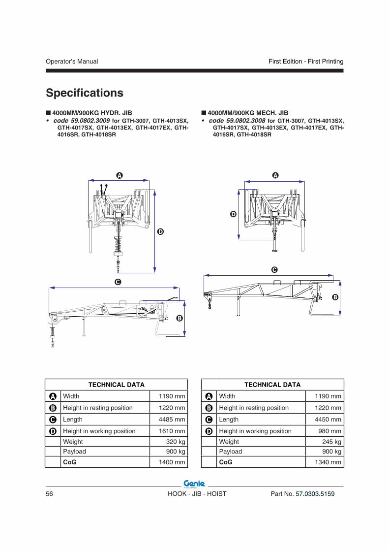
Operator’s Manual
56 HOOK - JIB - HOIST Part No. 57.0303.5159
First Edition - First Printing
Specifi cations
4000MM/900KG MECH. JIB • code 59.0802.3008 for GTH-3007, GTH-4013SX,
GTH-4017SX, GTH-4013EX, GTH-4017EX, GTH-4016SR, GTH-4018SR
�
�
�
�
TECHNICAL DATA
� Width 1190 mm
� Height in resting position 1220 mm
� Length 4450 mm
� Height in working position 980 mm
Weight 245 kg
Payload 900 kg
CoG 1340 mm
4000MM/900KG HYDR. JIB • code 59.0802.3009 for GTH-3007, GTH-4013SX,
GTH-4017SX, GTH-4013EX, GTH-4017EX, GTH-4016SR, GTH-4018SR
�
�
�
�
TECHNICAL DATA
� Width 1190 mm
� Height in resting position 1220 mm
� Length 4485 mm
� Height in working position 1610 mm
Weight 320 kg
Payload 900 kg
CoG 1400 mm

First Edition - First Printing Operator’s Manual
Part No. 57.0303.5159 HOOK - JIB - HOIST 57
2000MM/2000KG JIB• code 59.0802.3007 for GTH-2506, GTH-3007, GTH-
4013SX, GTH-4017SX, GTH-4013EX, GTH-4017EX, GTH-4016SR, GTH-4018SR
�
�
�
�
Specifi cations
3000kg HOIST• code 59.0901.9002 for GTH-4013SX, GTH-4017SX,
GTH-4013EX, GTH-4017EX, GTH-4016SR, GTH-4018SR
�
�
�
�
TECHNICAL DATA
� Width 1335 mm
� Height in resting position 1080 mm
� Length 2290 mm
� Height in working position 800 mm
Weight 255 kg
Payload 2000 kg
CoG 490 mm
TECHNICAL DATA
� Width 1335 mm
� Height in resting position 1260 mm
� Length 830 mm
� Height in working position 1840 mm
Weight 350 kg
Payload 3000 kg
CoG 260 mm

Operator’s Manual
58 HOOK - JIB - HOIST Part No. 57.0303.5159
First Edition - First Printing
Intentionally blank page

First Edition - First Printing Operator’s Manual
Part No. 57.0303.5159 HOOK - JIB - HOIST 59
Load Charts
FIXED HOOK ON PLATE COUPLED TO GTH-2506
0°
10°
20°
30°
40°
50°
60°
0132.90 m
AB
CD
E70°
2
5.78
m
1000
kg
2000
kg
0
1
2
3
4
5
6
4
2500
kg
1500
kg
900
kg
57.2900.0204 rev. 0
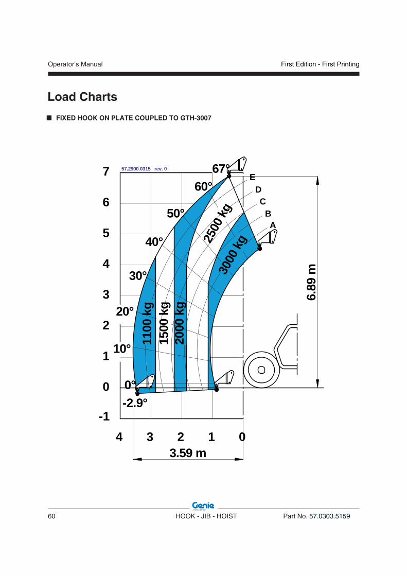
Operator’s Manual
60 HOOK - JIB - HOIST Part No. 57.0303.5159
First Edition - First Printing
Load Charts
57.2900.0315 rev. 0
01234
EDC
BA
30°
40°
50°
60°
20°
10°
0°-2.9°
67°
0
1
2
3
4
5
6
7
-1
6.89
m
3.59 m
1100
kg
2500
kg30
00kg
2000
kg
1500
kg
FIXED HOOK ON PLATE COUPLED TO GTH-3007

First Edition - First Printing Operator’s Manual
Part No. 57.0303.5159 HOOK - JIB - HOIST 61
Load Charts
FIXED HOOK ON PLATE COUPLED TO GTH-4013 SX & GTH-4013 EX
57.2900.0219 rev. A
012345678910
0
-1
1
2
3
4
5
6
7
8
9
10
11
12
13
20°
0°
10°
30°
40°
50°
60°
68.8°
A
B
C
D
E
-4.18°
3000
kg
250
kg
1 000
kg
12.6
9 m
500
kg
2000
kg
8.62 m57.2900.0220 rev. A
012345678910
0
-1
1
2
3
4
5
6
7
8
9
10
11
12
13
1500
kg
2500
kg20°
0°
10°
30°
40°
50°
60°
70°
A
B
C
D
E
71.6°
-1.43°
3000
kg
2000
kg
1250
kg
8.57 m
12.9
2 m

Operator’s Manual
62 HOOK - JIB - HOIST Part No. 57.0303.5159
First Edition - First Printing
Load Charts
FIXED HOOK ON PLATE COUPLED TO GTH-4017 SX & GTH-4017 EX

First Edition - First Printing Operator’s Manual
Part No. 57.0303.5159 HOOK - JIB - HOIST 63
Load Charts
FIXED HOOK ON PLATE COUPLED TO GTH-4016 SR
0
-1
1
2
3
4
5
6
7
8
9
10
11
12
13
14
15
16
A
B
12345678910111214
70° 75°
C
D
E
20°
30°
40°
50°
60°
900
kg
17
2000
kg
4000
kg
1500
kg
3000
kg
1000
kg
15.9
4 m
12.91 m
13 0
-3.7°
0°
10°
57.2900.0322 rev. A
0
-1
1
2
3
4
5
6
7
8
9
10
11
12
13
14
15
16
A
B
12345678910111214
70° 75°
C
D
E
20°
30°
40°
50°
60°
15.7
9 m
0°
10° 500
kg
1000
kg
2000
kg
4000
kg
1500
kg
3000
kg
12.91 m
-3.7°
13 0
350
kg
57.2900.0324 rev. A
0
-1
1
2
3
4
5
6
7
8
9
10
11
12
13
14
15
16
A
B
12345678910111214
70° 75°
C
D
E
20°
30°
40°
50°
60°
17
1000
kg
4000
kg
750
kg
1500
kg
3000
kg
2000
kg
600
kg
15.9
4 m
12.91 m
13
-3.7°
0
10°
0°
57.2900.0323 rev. A
0
-1
1
2
3
4
5
6
7
8
9
10
11
12
13
14
15
16
A
B
12345678910111214
10°
70° 75°
C
D
E
20°
30°
40°
50°
60°
2000
kg
300
kg
750
kg
1500
kg25
00 kg
1000
kg
0 kg
500
kg
12.91 m
15.7
9 m
-3.7°
0°
13 0
57.2900.0325 rev. A

Operator’s Manual
64 HOOK - JIB - HOIST Part No. 57.0303.5159
First Edition - First Printing
Load Charts
FIXED HOOK ON PLATE COUPLED TO GTH-4018 SR

First Edition - First Printing Operator’s Manual
Part No. 57.0303.5159 HOOK - JIB - HOIST 65
Load Charts
4000mm/900kg HYDRAULIC and MECHANICAL JIB COUPLED TO GTH-3007
57.2900.0316 rev. 0
012345
30°
40°
50°
60°
20°
10°
0°-2.9°
67°
-1
6.93
m
7.18 m
0
1
2
3
4
5
6
7
678
8
EDC
B
900 kg
500
kg
450
kg 750
kg
A

Operator’s Manual
66 HOOK - JIB - HOIST Part No. 57.0303.5159
First Edition - First Printing
Load Charts
4000mm/900kg HYDRAULIC and MECHANICAL JIB COUPLED TO GTH-4013 SX & GTH-4013 EX
012345678910111213
0
1
2
3
4
5
6
7
8
9
10
11
12
13
14
15
16
17
-1-2
20°
0°
10°
30°
40°
50°
60°
68.8°
-4.18°
200
kg
E
D
C
B
900
kg
300
kg
A
12.17 m
16.2
4 m
600
kg
57.2900.0221 rev. A
0
1
2
3
4
5
6
7
8
9
10
11
12
13
14
15
16
17
-1
20°
0°
10°
30°
40°
50°
60°
70°
A
-1.43°012345678910111213
C
D
E
B
800
kg
900
kg
71.6°
12.11 m
16.5
5 m
57.2900.0222 rev. A
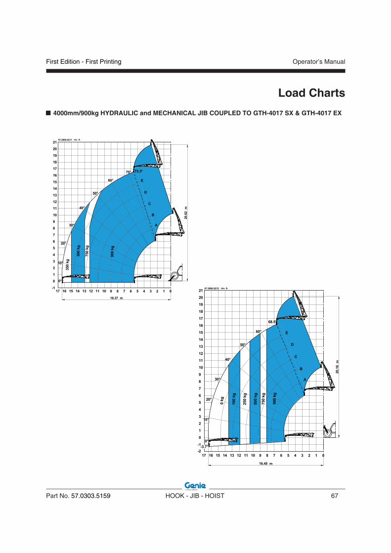
First Edition - First Printing Operator’s Manual
Part No. 57.0303.5159 HOOK - JIB - HOIST 67
Load Charts
4000mm/900kg HYDRAULIC and MECHANICAL JIB COUPLED TO GTH-4017 SX & GTH-4017 EX
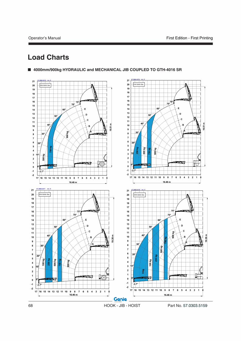
Operator’s Manual
68 HOOK - JIB - HOIST Part No. 57.0303.5159
First Edition - First Printing
Load Charts
4000mm/900kg HYDRAULIC and MECHANICAL JIB COUPLED TO GTH-4016 SR

First Edition - First Printing Operator’s Manual
Part No. 57.0303.5159 HOOK - JIB - HOIST 69
Load Charts
4000mm/900kg HYDRAULIC and MECHANICAL JIB COUPLED TO GTH-4018 SR

Operator’s Manual
70 HOOK - JIB - HOIST Part No. 57.0303.5159
First Edition - First Printing
0°
10°
20°
30°
40°
50°
60°
0
0134.51 m
AB
CD
E70°
2
1
2
3
4
5
6
5.78
m
45
1250
kg
850
kg
650
kg
550
kg
57.2900.0206 rev. A
Load Charts
2000mm/2000kg JIB COUPLED TO GTH-2506

First Edition - First Printing Operator’s Manual
Part No. 57.0303.5159 HOOK - JIB - HOIST 71
57.2900.0317 rev. 0
012345
30°
40°
50°
60°
20°
10°
0°-2.9°
67°
-1
7.13
m
5.17 m
0
1
2
3
4
5
6
7
6
8
EDC
BA
1500
kg
750
kg
1000
kg
2000
kg
Load Charts
2000mm/2000kg JIB COUPLED TO GTH-3007

Operator’s Manual
72 HOOK - JIB - HOIST Part No. 57.0303.5159
First Edition - First Printing
Load Charts
2000mm/2000kg JIB COUPLED TO GTH-4013 SX & GTH-4013 EX
57.2900.0441 rev. 0
0°
68.9°
-4.18°012345678911
0
-1
1
2
3
4
5
6
7
8
9
10
11
12
13
D
E
10
14
150
kg
15
16
500
kg
1500
kg
250
kg
1000
kg
2000
kg
A
B
C
14.8
4 m
20°
10°
30°
40°
50°
60°
10.28 m57.2900.0442 rev. 0
2000
kg
012345678910
0-1
1
2
3
4
5
6
7
8
9
10
11
12
13
1500
kg
1150
kg
20°
0°
10°
30°
40°
50°
60°
70°
A
B
C
D
E71.6°
-1.43°
14
15
16
10.21 m
15.0
7 m
11

First Edition - First Printing Operator’s Manual
Part No. 57.0303.5159 HOOK - JIB - HOIST 73
Load Charts
2000mm/2000kg JIB COUPLED TO GTH-4017 SX & GTH-4017 EX

Operator’s Manual
74 HOOK - JIB - HOIST Part No. 57.0303.5159
First Edition - First Printing
Load Charts
2000mm/2000kg JIB COUPLED TO GTH-4016 SR

First Edition - First Printing Operator’s Manual
Part No. 57.0303.5159 HOOK - JIB - HOIST 75
Load Charts
2000mm/2000kg JIB COUPLED TO GTH-4018 SR

Operator’s Manual
76 HOOK - JIB - HOIST Part No. 57.0303.5159
First Edition - First Printing
Load Charts
3000 kg HOIST COUPLED TO GTH-4013 SX & GTH-4013 EX
57.2900.0223 rev. A
0123456789
0
-1
1
2
3
4
5
6
7
8
9
10
11
12
13
20°
30°
40°
50°
60°
70°
A
B
C
D
E
71.6°
-1.43°
8.45 m
0°
2500
kg
1500
kg
2000
kg
3000
kg
1000
kg
12.3
9 m
10°
57.2900.0224 rev. A
012345678910
0
-1
1
2
3
4
5
6
7
8
9
10
11
12
13
20°
0°
10°
30°
40°
50°
60°
68.8°
A
B
C
D
E
-4.18°
12.1
6 m
500
kg
2000
kg
8.49 m
3000
kg
1000
kg
250
kg

First Edition - First Printing Operator’s Manual
Part No. 57.0303.5159 HOOK - JIB - HOIST 77
Load Charts
3000 kg HOIST COUPLED TO GTH-4017 SX & GTH-4017 EX

Operator’s Manual
78 HOOK - JIB - HOIST Part No. 57.0303.5159
First Edition - First Printing
Load Charts
3000 kg HOIST COUPLED TO GTH-4016 SR
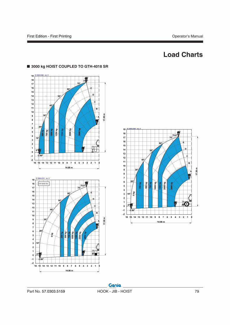
First Edition - First Printing Operator’s Manual
Part No. 57.0303.5159 HOOK - JIB - HOIST 79
Load Charts
3000 kg HOIST COUPLED TO GTH-4018 SR

Operator’s Manual
80 HOOK - JIB - HOIST Part No. 57.0303.5159
First Edition - First Printing
Intentionally blank page
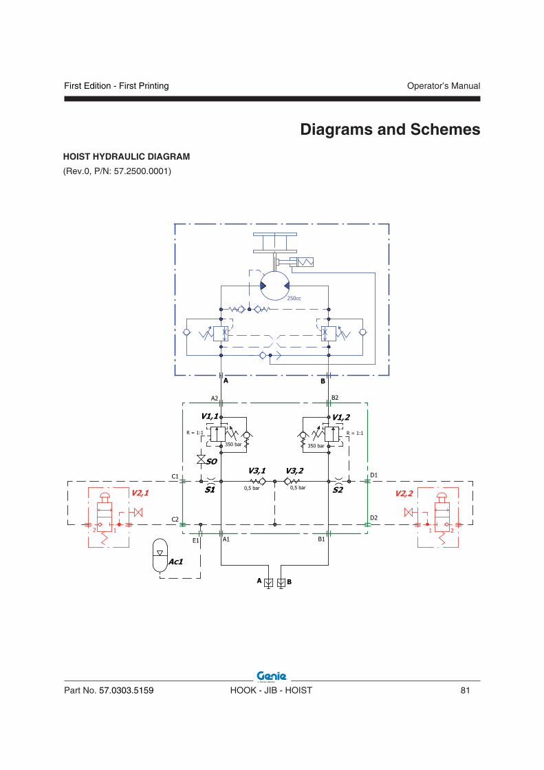
First Edition - First Printing Operator’s Manual
Part No. 57.0303.5159 HOOK - JIB - HOIST 81
Diagrams and Schemes
HOIST HYDRAULIC DIAGRAM
(Rev.0, P/N: 57.2500.0001)

Operator’s Manual
82 HOOK - JIB - HOIST Part No. 57.0303.5159
First Edition - First Printing
Diagrams and Schemes
JIB HYDRAULIC DIAGRAM
(Rev.0, P/N: 57.2500.0000)

First Edition - First Printing Operator’s Manual
Part No. 57.0303.5159 HOOK - JIB - HOIST 83
Beaufort Wind Scale
BeaufortNumber
DescriptionWind Speed
m/sLand Condition
0 Calm < 0.3. Calm. Smoke rises vertically.1 Light air 0.3 - 1.5 Wind motion visible in smoke.2 Light breeze 1.6 - 3.4 Wind felt on exposed skin. Leaves rustle.
3Gentle breeze
3.5 - 5.4 Leaves and smaller twigs in constant motion.
4Moderate
breeze5.5 - 7.9
Dust and loose paper raised. Small branches begin to move.
5 Fresh breeze 8.0 - 10.7Branches of a moderate size move. Small trees begin to sway.
6Strong breeze
10.8 - 13.8Large branches in motion. Whistling heard in overhead wires. Umbrella use becomes diffi-cult. Empty plastic garbage cans tip over.
7
High wind, Moderate gale, Near
gale
13.9 - 17.1
Whole trees in motion. Effort needed to walk against the wind. Swaying of skyscrapers may be felt, especially by people on upper floors.
8Gale, fresh
gale17.2 - 20.7
Some twigs broken from trees. Cars veer on road. Progress on foot is seriously impeded.
9 Strong gale 20.8 - 24.4
Some branches break off trees, and some small trees blow over. Construction/tempora-ry signs and barricades blow over. Damage to circus tents and canopies.
10Storme,
whole gale24.5 - 28.4
Trees are broken off or uprooted, saplings bent and deformed. Poorly attached asphalt shingles and shingles in poor condition peel off roofs.
11 Violent storm 28.5 - 32.6
Widespread damage to vegetation. Many ro-ofing surfaces are damaged; asphalt tiles that have curled up and/or fractured due to age may break away completely.
12Hurricane
force32.7 >
Very widespread damage to vegetation. Some windows may break; mobile homes and poorly constructed sheds and barns are damaged. Debris may be hurled about.

Operator’s Manual
84 HOOK - JIB - HOIST Part No. 57.0303.5159
First Edition - First Printing
Intentionally blank page

First Edition - First Printing Operator’s Manual
Part No. 57.0303.5159 HOOK - JIB - HOIST 85
Tables of Material
Material Weight in kg per m3
Aluminium 2700Brass 8500Brick 2100Coal 1450Copper 8800Concrete 2400Iron-steel 7700Lead 11200Oil 800Paper 1120Water 1000Wood 800
MATERIAL WEIGHTS
VOLUMES OF COMMON SHAPES
Pyramid¼ x L x W x H
Solid Cylinderπr2 x L
Thick Walled Pipeπ(r12 - r22) x L
Rectangular SolidL x W x H
Sphere4π x R3

Operator’s Manual
86 HOOK - JIB - HOIST Part No. 57.0303.5159
First Edition - First Printing
Intentionally blank page

First Edition - First Printing Operator’s Manual
Part No. 57.0303.5159 HOOK - JIB - HOIST 87
EC Declaration of Conformity
EC DECLARATION OF CONFORMITY FULL TEXT
Manufacturer and person authorized to compile the technical file TEREXLIFT s.r.l. Zona IndustrialeBuzzacchero 06019 Umbertide (PG) ItaliaHereby declares that the machinery described belowDesignation: Mobile Elevating Work Platform (MEWP)Function: Lifting persons and goodsModel XXXXXSerial Number XXXXXcomplies with the relevant provisions of the machinery directive 2006/42/EC enclosure IVcomplies with the model which has obtained an "EC" type certificate, n° XXXXXXXXX, Issued by the following notified body XXXXXAlso complies with the following European Standards, National Standards and technical provisions:EN 280/A2:2009
EXAMPLE OF LAYOUT
EXAMPLEEXAMPLE

Operator’s Manual
88 HOOK - JIB - HOIST Part No. 57.0303.5159
First Edition - First Printing
Intentionally blank page

First Edition - First Printing Operator’s Manual
Part No. 57.0303.5159 HOOK - JIB - HOIST 89
Routine Check Schedule
SAFETY DEVICES DAILY CHECKING
COMPONENT RESULT NOTE SIGNATURE
Telehandler LMI Unit Control
positive negative
Winch Fluid Powered Locking Valve
positive negative
Winch Parking Brake positive negative
Winch Limit Switches positive negative
Winch Hoist Limiting Mechanism
positive negative
Hook Tip positive negative
DATE__________________________