Operator's Manual MODEL PB-251 - ECHO-USA...SPARK ARRESTOR - CATALYTIC MUFFLER / MUFFLER - The...
24
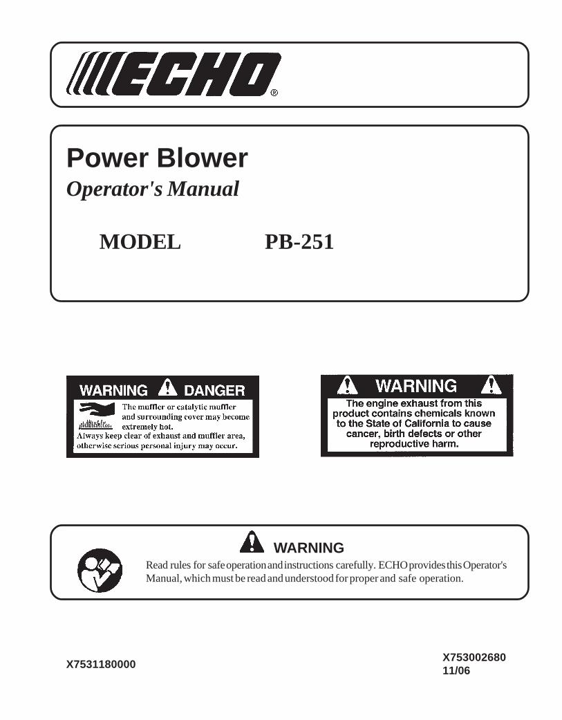
Power Blower Operator's Manual MODEL PB-251 X753002680 11/06 X7531180000 WARNING Read rules for safe operation and instructions carefully. ECHO provides this Operator's Manual, which must be read and understood for proper and safe operation.
Transcript of Operator's Manual MODEL PB-251 - ECHO-USA...SPARK ARRESTOR - CATALYTIC MUFFLER / MUFFLER - The...
Power BlowerOperator's Manual
MODEL PB-251
X75300268011/06X7531180000
WARNINGRead rules for safe operation and instructions carefully. ECHO provides this Operator'sManual, which must be read and understood for proper and safe operation.
2
Copyright© 2006 By Echo, IncorporatedAll Rights Reserved.
TABLE OF CONTENTS
Introduction ............................................................... 2- The Operator's Manual ....................................... 2
Safety ......................................................................... 3- Manual Safety Symbols and Important
Information ......................................................... 3- International Symbols ........................................ 3- Personal Condition and Safety Equipment ......... 3- Equipment Check ................................................ 6
Emission Control ....................................................... 6Description ................................................................ 7Contents .................................................................... 8Assembly ................................................................... 9
- Blower Application ............................................. 9Operation ................................................................. 10
- Fuel ................................................................... 10- Starting Cold Engine ......................................... 11- Starting Warm Engine ....................................... 12- Stopping Engine ............................................... 13- Operating Blower .............................................. 13
Maintenance ............................................................ 14- Skill Levels ........................................................ 14- Maintenance Intervals ...................................... 14- Air Filter ............................................................ 15- Fuel Filter .......................................................... 15- Spark Plug ......................................................... 16- Cooling System ................................................. 16- Exhaust System ................................................. 17- Carburetor Adjustment ..................................... 18
Troubleshooting ...................................................... 19Storage ..................................................................... 20Specifications ........................................................... 21Servicing Information ............................................... 24
- Parts/Serial Number .......................................... 24- Service .............................................................. 24- ECHO Consumer Product Support .................... 24- Warranty Card .................................................. 24- Additional or Replacement Manuals ................ 24
Specifications, descriptions and illustrative material in thisliterature are as accurate as known at the time of publica-tion, but are subject to change without notice. Illustrationsmay include optional equipment and accessories, and maynot include all standard equipment.
INTRODUCTION
Welcome to the ECHO family. This ECHO product was designed and manufactured to provide long life and on-the-jobdependability. Read and understand this manual. You will find it easy to use and full of helpful operating tips andSAFETY messages.
THE OPERATOR'S MANUALRead and understand this manual before operation. Keep it in a safeplace for future reference. It contains specifications and information foroperation, starting, stopping, maintenance, storage and assemblyspecific to this product.
Power BlowerOperator's Manual
MODEL PB-251
X7530009/06X753118
WARNINGRead rules for safe operation and instructions carefully. ECHO provides this Operator'sManual, which must be read and understood for proper and safe operation.
3POWER BLOWER
OPERATOR'S MANUAL
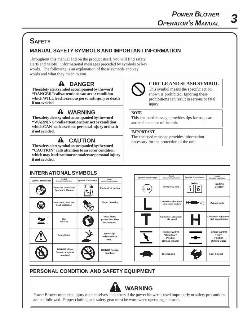
SAFETY
MANUAL SAFETY SYMBOLS AND IMPORTANT INFORMATION
Throughout this manual and on the product itself, you will find safetyalerts and helpful, informational messages preceded by symbols or keywords. The following is an explanation of those symbols and keywords and what they mean to you.
INTERNATIONAL SYMBOLSSymbol
description/application Symbol form/shapeSymbol
description/applicationSymbol form/shape
Read and understandOperator's Manual.
Fuel and oil mixture
HotSurface
Wear eyes, ears andhead protection
Finger Severing
Safety/Alert
Wear handprotection. Use
two handed.
DO NOT smokenear fuel.
DO NOT allowflames or sparks
near fuel.
Wear slipresistant foot
wear.
PERSONAL CONDITION AND SAFETY EQUIPMENT
WARNINGPower Blower users risk injury to themselves and others if the power blower is used improperly or safety precautionsare not followed. Proper clothing and safety gear must be worn when operating a blower.
WARNINGThe safety alert symbol accompanied by the word“WARNING” calls attention to an act or conditionwhich CAN lead to serious personal injury or deathif not avoided.
CIRCLE AND SLASH SYMBOLThis symbol means the specific actionshown is prohibited. Ignoring theseprohibitions can result in serious or fatalinjury.
CAUTIONThe safety alert symbol accompanied by the word“CAUTION” calls attention to an act or conditionwhich may lead to minor or moderate personal injuryif not avoided.
NOTEThis enclosed message provides tips for use, careand maintenance of the unit.
IMPORTANTThe enclosed message provides informationnecessary for the protection of the unit.
DANGERThe safety alert symbol accompanied by the word“DANGER” calls attention to an act or conditionwhich WILL lead to serious personal injury or deathif not avoided.
Symboldescription/application Symbol form/shape
Symboldescription/applicationSymbol form/shape
Carburetor adjustment- Idle speed
Carburetor adjustment- High speed mixture
Emergency stop
Carburetor adjustment- Low speed mixture
IgnitionON/OFF
Primer bulb
Choke Control"Cold Start"
Position(Choke Closed)
Choke Control"Run"
Position(Choke Open)
Idle Speed Fast Speed
4
Physical ConditionYour judgment and physical dexterity may not be good:
• if you are tired or sick,• if you are taking medication,• if you have taken alcohol or drugs.
Operate unit only if you are physically and mentally well.
Eye ProtectionWear eye protection that meets ANSI Z87.1 or CE requirements whenever you operate the unit.
Hand ProtectionWear no-slip, heavy-duty work gloves to improve your grip on the blower handle. Gloves also reduce the transmissionof machine vibration to your hands.
Breathing ProtectionWear a facemask to protect against dust.
Hearing ProtectionECHO recommends wearing hearing protection whenever unit is used.
Proper ClothingWear snug fitting, durable clothing;
• Pants should have long legs, shirts with long sleeves.• DO NOT WEAR SHORTS,• DO NOT WEAR TIES, SCARVES, and JEWELRY.
Wear sturdy work shoes with nonskid soles:• DO NOT WEAR OPEN TOED SHOES,• DO NOT OPERATE UNIT BAREFOOTED.
Keep long hair away from engine and blower intake. Retain hair with cap or net.
Hot Humid WeatherHeavy protective clothing can increase operator fatigue, which may lead to heat stroke. Schedule heavy work for earlymorning or late afternoon hours when temperatures are cooler.
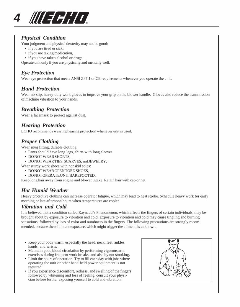
Vibration and ColdIt is believed that a condition called Raynaud’s Phenomenon, which affects the fingers of certain individuals, may bebrought about by exposure to vibration and cold. Exposure to vibration and cold may cause tingling and burningsensations, followed by loss of color and numbness in the fingers. The following precautions are strongly recom-mended, because the minimum exposure, which might trigger the ailment, is unknown.
• Keep your body warm, especially the head, neck, feet, ankles,hands, and wrists.
• Maintain good blood circulation by performing vigorous armexercises during frequent work breaks, and also by not smoking.
• Limit the hours of operation. Try to fill each day with jobs whereoperating the unit or other hand-held power equipment is notrequired.
• If you experience discomfort, redness, and swelling of the fingersfollowed by whitening and loss of feeling, consult your physi-cian before further exposing yourself to cold and vibration.
5POWER BLOWER
OPERATOR'S MANUAL
Repetitive Stress InjuriesIt is believed that overusing the muscles and tendons of the fingers, hands, arms, and shoulders may cause soreness,swelling, numbness, weakness, and extreme pain in those areas. Certain repetitive hand activities may put you at a highrisk for developing a Repetitive Stress Injury (RSI). An extreme RSI condition is Carpal Tunnel Syndrome (CTS), whichcould occur when your wrist swells and squeezes a vital nerve that runs through the area.Some believe that prolonged exposure to vibration may contribute to CTS. CTS can cause severe pain for months oreven years.
To reduce the risk of RSI/CTS, do the following:• Avoid using your wrist in a bent, extended, or twisted position.
Instead try to maintain a straight wrist position. Also, whengrasping, use your whole hand, not just the thumb and indexfinger.
• Take periodic breaks to minimize repetition and rest your hands.• Reduce the speed and force with which you do the repetitive
movement.• Do exercises to strengthen the hand and arm muscles.• Immediately stop using all power equipment and consult a
doctor if you feel tingling, numbness, or pain in the fingers,hands, wrists, or arms. The sooner RSI/CTS is diagnosed, themore likely permanent nerve and muscle damage can be pre-vented.
DANGERDo not operate this product indoors or in inadequately ventilatedareas. Engine exhaust contains poisonous emissions and cancause serious injury or death.
Read the Manuals• Provide all users of this equipment with the Operator’s Manual
and Safety Manual for instructions on Safe Operation.
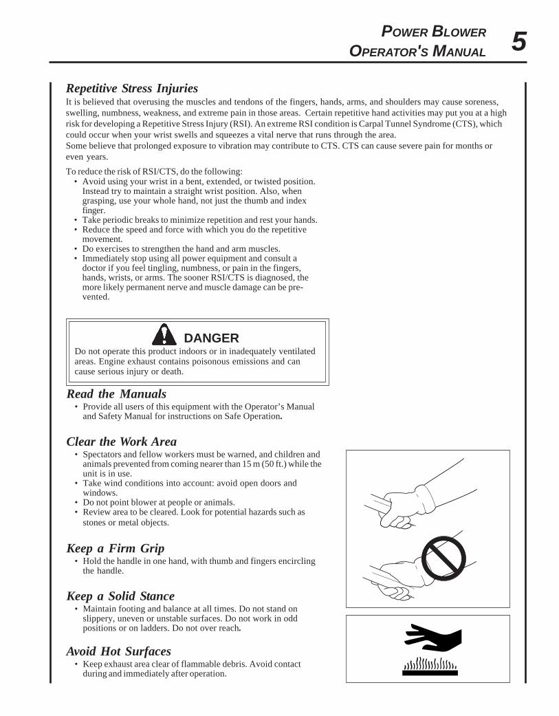
Clear the Work Area• Spectators and fellow workers must be warned, and children and
animals prevented from coming nearer than 15 m (50 ft.) while theunit is in use.
• Take wind conditions into account: avoid open doors andwindows.
• Do not point blower at people or animals.• Review area to be cleared. Look for potential hazards such as
stones or metal objects.
Keep a Firm Grip• Hold the handle in one hand, with thumb and fingers encircling
the handle.
Keep a Solid Stance• Maintain footing and balance at all times. Do not stand on
slippery, uneven or unstable surfaces. Do not work in oddpositions or on ladders. Do not over reach.
Avoid Hot Surfaces• Keep exhaust area clear of flammable debris. Avoid contact
during and immediately after operation.
6
EQUIPMENT CHECK
WARNINGUse only ECHO approved attachments. Serious injury may result from the use of a non-approved attachmentcombination. ECHO, INC. will not be responsible for the failure of cutting devices, attachments or accessories whichhave not been tested and approved by ECHO. Read and comply with all safety instructions listed in this manual andsafety manual.
• Check unit for loose/missing nuts, bolts and screws. Tighten and/or replace as needed.
• Inspect fuel lines, tank and area around carburetor for fuel leaks. DO NOT operate unit if leaks are found.
• Do not use blower if any part is missing or damaged.
• Have repairs done only by an authorized ECHO Service dealer.
• Do not use any attachment, accessory or replacement part unless it is recommended in this Operator's Manual.
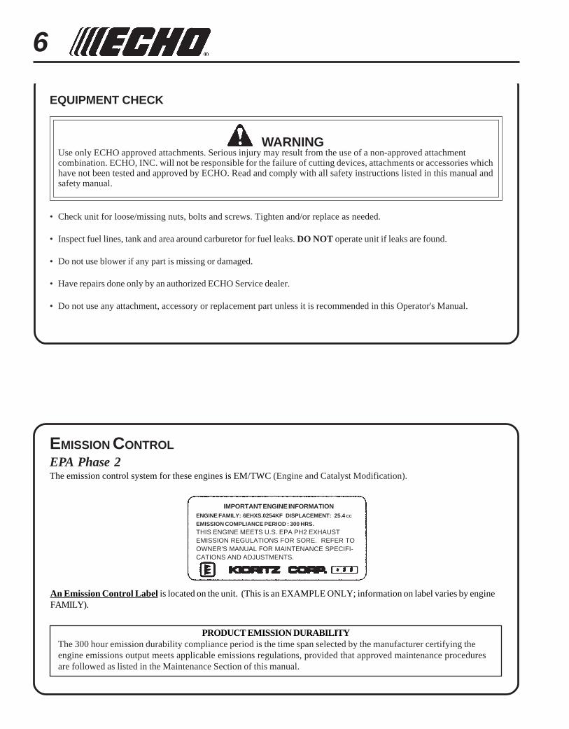
IMPORTANT ENGINE INFORMATIONENGINE FAMILY: 6EHXS.0254KF DISPLACEMENT: 25.4 CC
EMISSION COMPLIANCE PERIOD : 300 HRS.
THIS ENGINE MEETS U.S. EPA PH2 EXHAUSTEMISSION REGULATIONS FOR SORE. REFER TOOWNER'S MANUAL FOR MAINTENANCE SPECIFI-CATIONS AND ADJUSTMENTS.
EMISSION CONTROLEPA Phase 2The emission control system for these engines is EM/TWC (Engine and Catalyst Modification).
An Emission Control Label is located on the unit. (This is an EXAMPLE ONLY; information on label varies by engineFAMILY).
PRODUCT EMISSION DURABILITYThe 300 hour emission durability compliance period is the time span selected by the manufacturer certifying theengine emissions output meets applicable emissions regulations, provided that approved maintenance proceduresare followed as listed in the Maintenance Section of this manual.
7POWER BLOWER
OPERATOR'S MANUAL
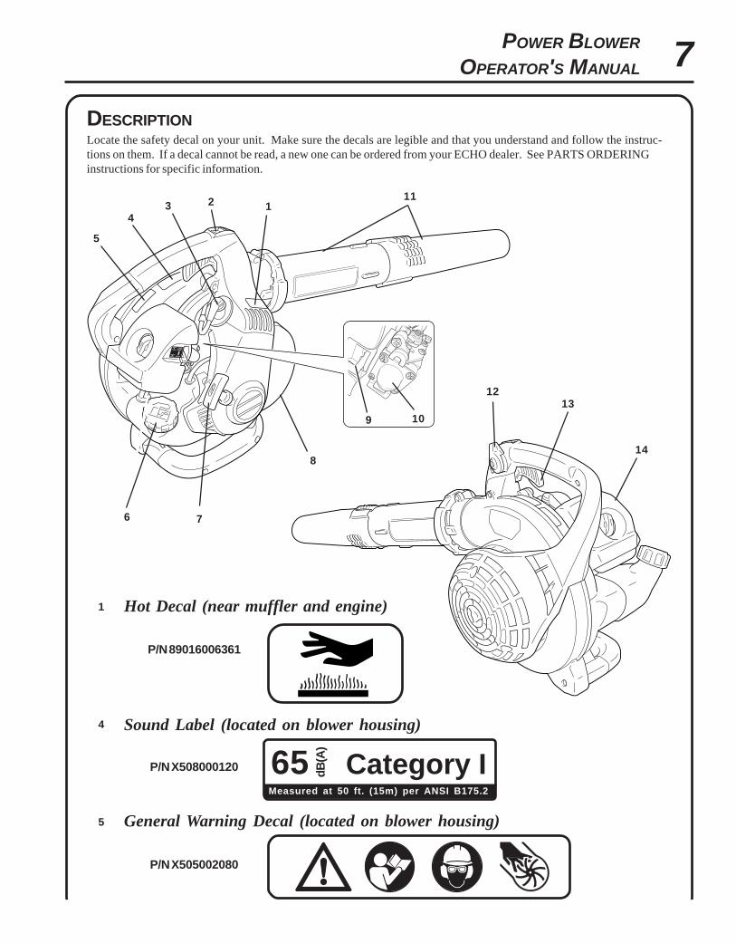
DESCRIPTIONLocate the safety decal on your unit. Make sure the decals are legible and that you understand and follow the instruc-tions on them. If a decal cannot be read, a new one can be ordered from your ECHO dealer. See PARTS ORDERINGinstructions for specific information.
P/N 89016006361
P/N X505002080
65 Category IdB(A
)
Measured at 50 ft. (15m) per ANSI B175.2
Hot Decal (near muffler and engine)
General Warning Decal (located on blower housing)
P/N X508000120
Sound Label (located on blower housing)
1
5
4
12
4
5
6 7
9 10
1213
14
3
8
11
8
1. SAFETY DECAL - Lists important safety precautions.
2. STOP SWITCH - "SLIDE SWITCH" mounted on top of handle. Push forward to start and run. Slide back to stop.
3. SPARK PLUG - Provides spark to ignite fuel mixture.4. SAFETY DECAL - Lists important safety precautions.
5. SAFETY DECAL - Lists important safety precautions.
6. FUEL TANK CAP - Covers and seals fuel tank.7. RECOIL STARTER HANDLE - Pull recoil handle slowly until recoil starter engages, then quickly and firmly. When
engine starts, return handle slowly. DO NOT let handle snap back or damage to unit will occur.
8. SPARK ARRESTOR - CATALYTIC MUFFLER / MUFFLER -The muffler or catalytic muffler controls exhaust noiseand emission. The spark arrestor screen prevents hot, glowing particles of carbon from leaving the muffler. Keep
exhaust area clear of flammable debris.
9. CHOKE - Choke is located on top of the air cleaner. Move choke lever to "COLD START" ( ) to close choke forcold starting. Move choke lever to "RUN" ( ) position to open choke.
10. PURGE BULB - Pumping purge bulb before starting engine draws fresh fuel from the fuel tank, purging air from the
carburetor. Pump purge bulb until fuel is visible and flows freely in the clear fuel tank return line. Pump purge bulban additional 4 or 5 times..
11. BLOWER PIPES - Exclusive positive locking system.
12. THROTTLE POSITION LEVER - Pull back to increase engine speed. Friction washers maintain throttle leversetting.
13. THROTTLE TRIGGER - Spring loaded to return to idle when released. During acceleration, press trigger gradually
for best operating technique.14. AIR CLEANER - Contains replaceable air filter element.
CONTENTS
1 - Power Head1 - Blower Pipe (main)1 - Blower Pipe1 - Operator's Manual1 - Warranty Registration Card1 - ECHO Emissions and Warranty Statement1 - Echo Power Blend TM 2-stroke oil sample
Power BlowerOperator's Manual
MODEL PB-251
X7530009/06X753118
WARNINGRead rules for safe operation and instructions carefully. ECHO provides this Operator'sManual, which must be read and understood for proper and safe operation.
9POWER BLOWER
OPERATOR'S MANUAL
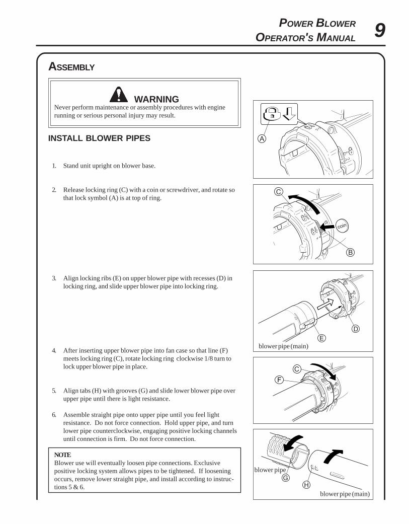
ASSEMBLY
WARNINGNever perform maintenance or assembly procedures with enginerunning or serious personal injury may result.
INSTALL BLOWER PIPES
1. Stand unit upright on blower base.
2. Release locking ring (C) with a coin or screwdriver, and rotate sothat lock symbol (A) is at top of ring.
3. Align locking ribs (E) on upper blower pipe with recesses (D) inlocking ring, and slide upper blower pipe into locking ring.
4. After inserting upper blower pipe into fan case so that line (F)meets locking ring (C), rotate locking ring clockwise 1/8 turn tolock upper blower pipe in place.
5. Align tabs (H) with grooves (G) and slide lower blower pipe overupper pipe until there is light resistance.
6. Assemble straight pipe onto upper pipe until you feel lightresistance. Do not force connection. Hold upper pipe, and turnlower pipe counterclockwise, engaging positive locking channelsuntil connection is firm. Do not force connection.
NOTEBlower use will eventually loosen pipe connections. Exclusivepositive locking system allows pipes to be tightened. If looseningoccurs, remove lower straight pipe, and install according to instruc-tions 5 & 6.
blower pipe (main)
blower pipe (main)
blower pipe
10
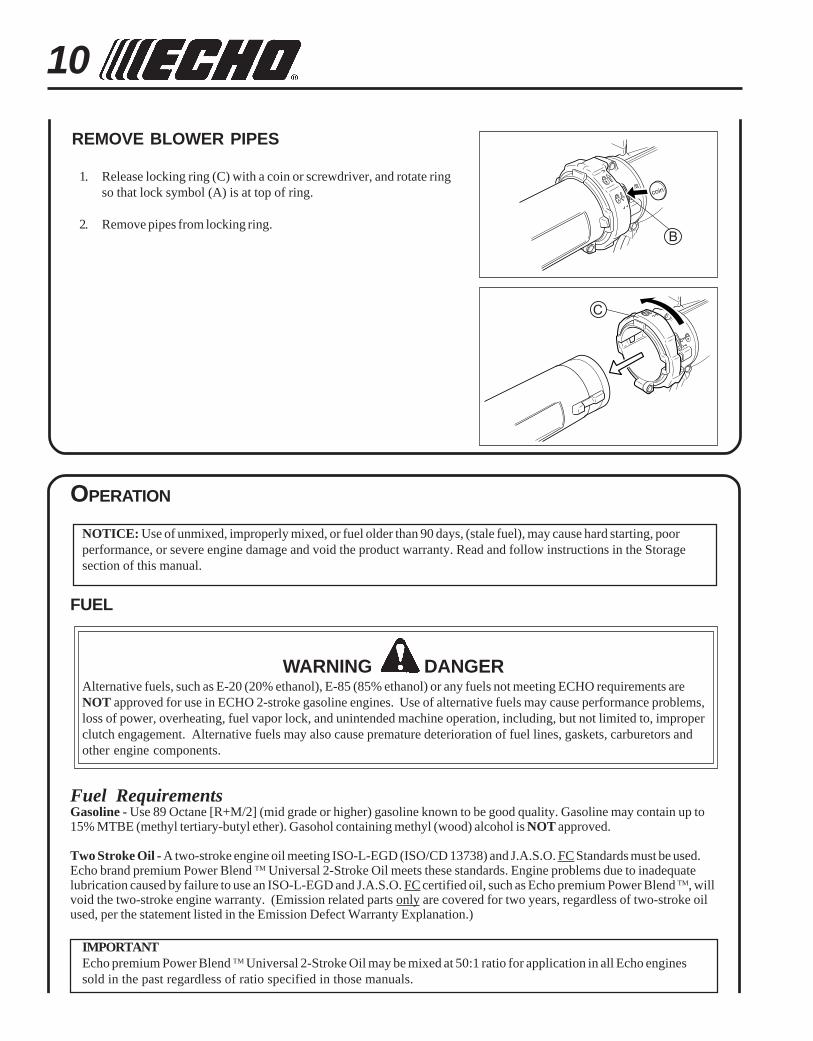
REMOVE BLOWER PIPES
1. Release locking ring (C) with a coin or screwdriver, and rotate ringso that lock symbol (A) is at top of ring.
2. Remove pipes from locking ring.
OPERATION
NOTICE: Use of unmixed, improperly mixed, or fuel older than 90 days, (stale fuel), may cause hard starting, poorperformance, or severe engine damage and void the product warranty. Read and follow instructions in the Storagesection of this manual.
FUEL
WARNING DANGERAlternative fuels, such as E-20 (20% ethanol), E-85 (85% ethanol) or any fuels not meeting ECHO requirements areNOT approved for use in ECHO 2-stroke gasoline engines. Use of alternative fuels may cause performance problems,loss of power, overheating, fuel vapor lock, and unintended machine operation, including, but not limited to, improperclutch engagement. Alternative fuels may also cause premature deterioration of fuel lines, gaskets, carburetors andother engine components.
Fuel RequirementsGasoline - Use 89 Octane [R+M/2] (mid grade or higher) gasoline known to be good quality. Gasoline may contain up to15% MTBE (methyl tertiary-butyl ether). Gasohol containing methyl (wood) alcohol is NOT approved.
Two Stroke Oil - A two-stroke engine oil meeting ISO-L-EGD (ISO/CD 13738) and J.A.S.O. FC Standards must be used.Echo brand premium Power Blend TM Universal 2-Stroke Oil meets these standards. Engine problems due to inadequatelubrication caused by failure to use an ISO-L-EGD and J.A.S.O. FC certified oil, such as Echo premium Power Blend TM, willvoid the two-stroke engine warranty. (Emission related parts only are covered for two years, regardless of two-stroke oilused, per the statement listed in the Emission Defect Warranty Explanation.)
IMPORTANTEcho premium Power Blend TM Universal 2-Stroke Oil may be mixed at 50:1 ratio for application in all Echo enginessold in the past regardless of ratio specified in those manuals.
11POWER BLOWER
OPERATOR'S MANUAL
IMPORTANTSpilled fuel is a leading cause ofhydrocarbon emissions. Some statesmay require the use of automatic fuelshut-off containers to reduce fuelspillage.
After use• DO NOT store a unit with fuel in its tank.
Leaks can occur. Return unused fuel to anapproved fuel storage container.
Storage - Fuel storage laws vary by locality.Contact your local government for the lawsaffecting your area. As a precaution, storefuel in an approved, airtight container. Storein a well-ventilated, unoccupied building,away from sparks and flames.
IMPORTANTStored fuel ages. Do not mix more fuelthan you expect to use in thirty (30)days, ninety (90) days when a fuelstabilizer is added.
Handling Fuel
DANGERFuel is VERY flammable. Use extreme care when mixing, storing orhandling or serious personal injury may result.• Use an approved fuel container.• DO NOT smoke near fuel.• DO NOT allow flames or sparks near fuel.• Fuel tanks/cans may be under pressure. Always loosen fuel caps
slowly allowing pressure to equalize.• NEVER refuel a unit when the engine is HOT or RUNNING!• DO NOT fill fuel tanks indoors. ALWAYS fill fuel tanks outdoors
over bare ground.• DO NOT overfill fuel tank. Wipe up spills immediately.• Securely tighten fuel tank cap and close fuel container after
refueling.• Inspect for fuel leakage. If fuel leakage is found, do not start or
operate unit until leakage is repaired.• Move at least 3m (10 ft.) from refueling location before starting
the engine.
Mixing Instructions1. Fill an approved fuel container with half of the required amount
of gasoline.2. Add the proper amount of 2-stroke oil to gasoline.3. Close container and shake to mix oil with gasoline.4. Add remaining gasoline, close fuel container, and remix.
IMPORTANTStored two-stroke fuel may separate.ALWAYS shake fuel containerthoroughly before each use.
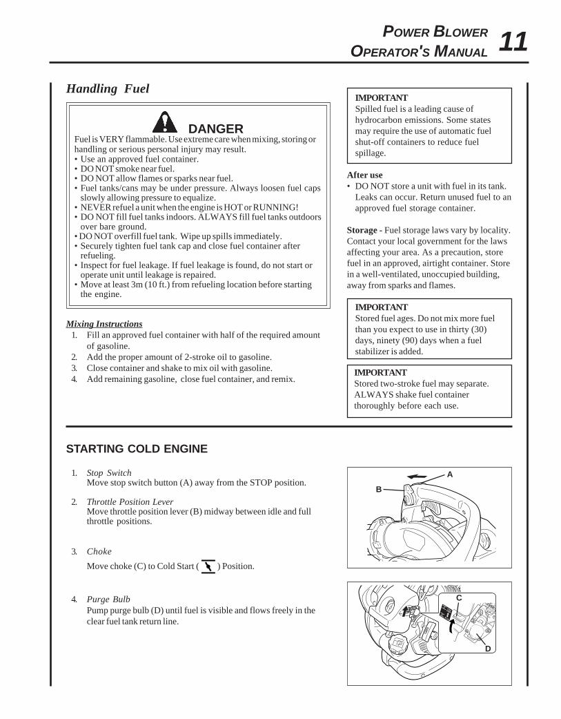
STARTING COLD ENGINE
1. Stop SwitchMove stop switch button (A) away from the STOP position.
2. Throttle Position LeverMove throttle position lever (B) midway between idle and fullthrottle positions.
3. Choke
Move choke (C) to Cold Start ( ) Position.
4. Purge BulbPump purge bulb (D) until fuel is visible and flows freely in theclear fuel tank return line.
B
A
D
C
12
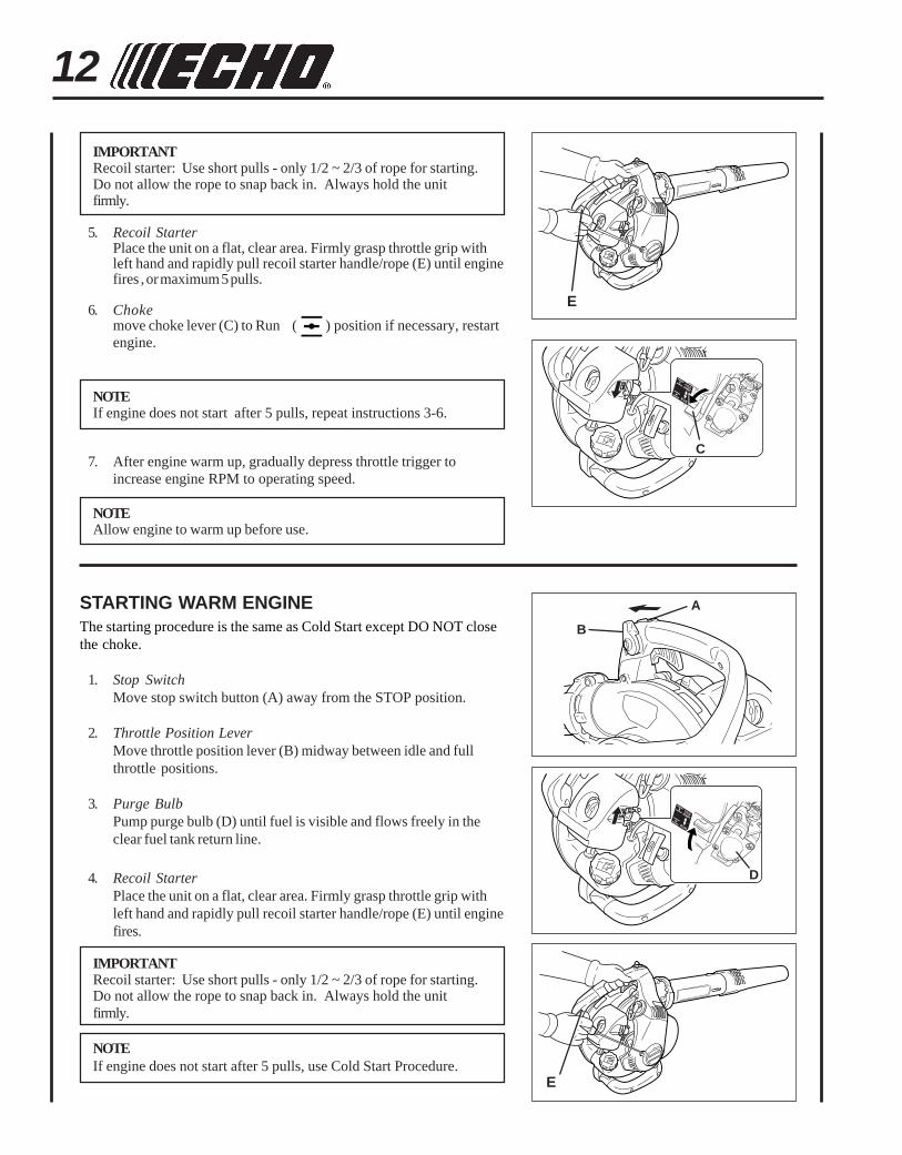
IMPORTANTRecoil starter: Use short pulls - only 1/2 ~ 2/3 of rope for starting.Do not allow the rope to snap back in. Always hold the unitfirmly.
5. Recoil StarterPlace the unit on a flat, clear area. Firmly grasp throttle grip withleft hand and rapidly pull recoil starter handle/rope (E) until enginefires , or maximum 5 pulls.
6. Chokemove choke lever (C) to Run ( ) position if necessary, restartengine.
NOTEIf engine does not start after 5 pulls, repeat instructions 3-6.
7. After engine warm up, gradually depress throttle trigger toincrease engine RPM to operating speed.
NOTEAllow engine to warm up before use.
STARTING WARM ENGINEThe starting procedure is the same as Cold Start except DO NOT closethe choke.
1. Stop SwitchMove stop switch button (A) away from the STOP position.
2. Throttle Position LeverMove throttle position lever (B) midway between idle and fullthrottle positions.
3. Purge BulbPump purge bulb (D) until fuel is visible and flows freely in theclear fuel tank return line.
4. Recoil StarterPlace the unit on a flat, clear area. Firmly grasp throttle grip withleft hand and rapidly pull recoil starter handle/rope (E) until enginefires.
IMPORTANTRecoil starter: Use short pulls - only 1/2 ~ 2/3 of rope for starting.Do not allow the rope to snap back in. Always hold the unitfirmly.
NOTEIf engine does not start after 5 pulls, use Cold Start Procedure.
E
C
E
B
A
D
13POWER BLOWER
OPERATOR'S MANUAL
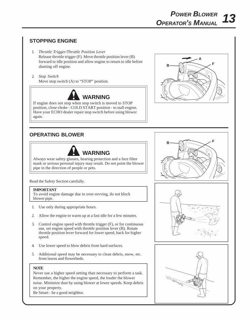
STOPPING ENGINE
1. Throttle Trigger/Throttle Position LeverRelease throttle trigger (F). Move throttle position lever (B)forward to idle position and allow engine to return to idle beforeshutting off engine.
2. Stop SwitchMove stop switch (A) to “STOP” position.
WARNINGIf engine does not stop when stop switch is moved to STOPposition, close choke - COLD START position - to stall engine.Have your ECHO dealer repair stop switch before using bloweragain.
F
OPERATING BLOWER
WARNINGAlways wear safety glasses, hearing protection and a face filtermask or serious personal injury may result. Do not point the blowerpipe in the direction of people or pets.
Read the Safety Section carefully.
IMPORTANTTo avoid engine damage due to over-revving, do not blockblower pipe.
1. Use only during appropriate hours.
2. Allow the engine to warm up at a fast idle for a few minutes.
3. Control engine speed with throttle trigger (F), or for continuoususe, set engine speed with throttle position lever (B). Rotatethrottle position lever forward for lower speed, back for higherspeed.
4. Use lower speed to blow debris from hard surfaces.
5. Additional speed may be necessary to clean debris, snow, etc.from lawns and flowerbeds.
NOTENever use a higher speed setting than necessary to perform a task.Remember, the higher the engine speed, the louder the blowernoise. Minimize dust by using blower at lower speeds. Keep debrison your property.Be Smart - be a good neighbor.
B
A
FB
14
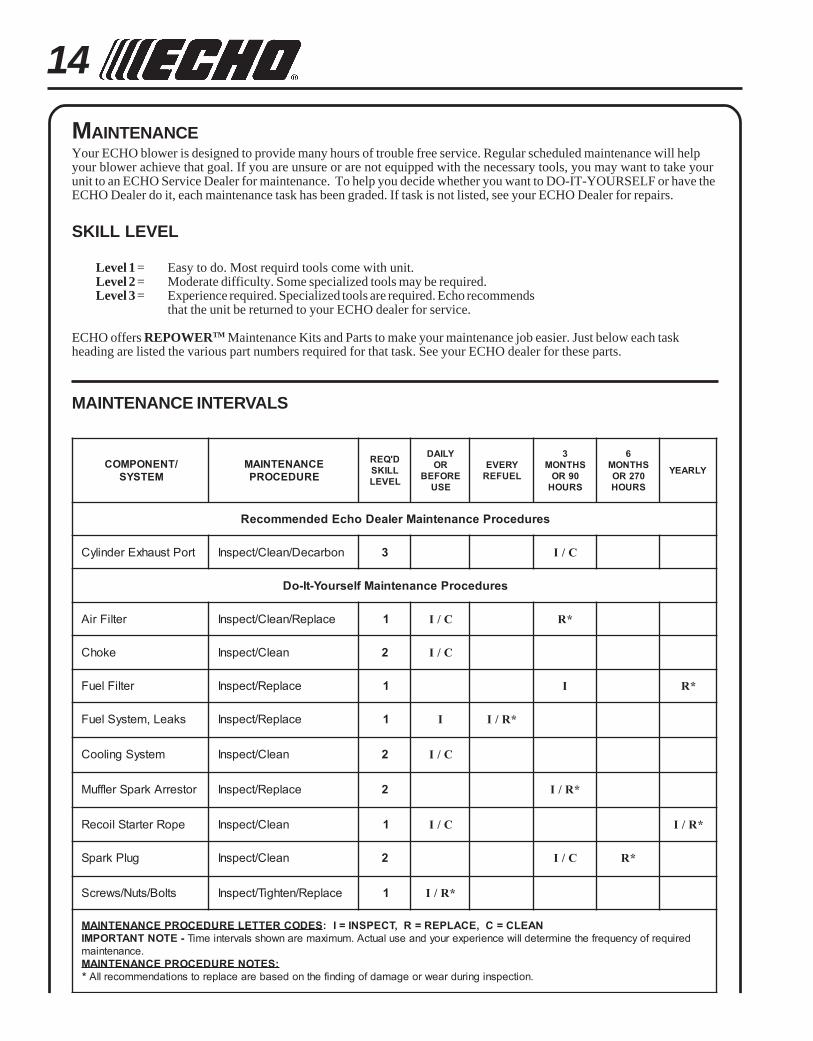
MAINTENANCEYour ECHO blower is designed to provide many hours of trouble free service. Regular scheduled maintenance will helpyour blower achieve that goal. If you are unsure or are not equipped with the necessary tools, you may want to take yourunit to an ECHO Service Dealer for maintenance. To help you decide whether you want to DO-IT-YOURSELF or have theECHO Dealer do it, each maintenance task has been graded. If task is not listed, see your ECHO Dealer for repairs.
SKILL LEVEL
Level 1 = Easy to do. Most requird tools come with unit.Level 2 = Moderate difficulty. Some specialized tools may be required.Level 3 = Experience required. Specialized tools are required. Echo recommends
that the unit be returned to your ECHO dealer for service.
ECHO offers REPOWERTM Maintenance Kits and Parts to make your maintenance job easier. Just below each taskheading are listed the various part numbers required for that task. See your ECHO dealer for these parts.
/TNENOPMOCMETSYS
ECNANETNIAMERUDECORP
D'QERLLIKSLEVEL
YLIADROEROFEB
ESU
YREVELEUFER
3SHTNOM09ROSRUOH
6SHTNOM072ROSRUOH
YLRAEY
serudecorPecnanetniaMrelaeDohcEdednemmoceR
troPtsuahxErednilyC nobraceD/naelC/tcepsnI 3 C/I
serudecorPecnanetniaMflesruoY-tI-oD
retliFriA ecalpeR/naelC/tcepsnI 1 C/I *R
ekohC naelC/tcepsnI 2 C/I
retliFleuF ecalpeR/tcepsnI 1 I *R
skaeL,metsySleuF ecalpeR/tcepsnI 1 I *R/I
metsySgnilooC naelC/tcepsnI 2 C/I
rotserrAkrapSrelffuM ecalpeR/tcepsnI 2 *R/I
epoRretratSlioceR naelC/tcepsnI 1 C/I *R/I
gulPkrapS naelC/tcepsnI 2 C/I *R
stloB/stuN/swercS ecalpeR/nethgiT/tcepsnI 1 *R/I
SEDOCRETTELERUDECORPECNANETNIAM NAELC=C,ECALPER=R,TCEPSNI=I:-ETONTNATROPMI deriuqerfoycneuqerfehtenimretedlliwecneirepxeruoydnaesulautcA.mumixameranwohsslavretniemiT
.ecnanetniam:SETONERUDECORPECNANETNIAM
* .noitcepsnignirudraewroegamadfognidnifehtnodesaberaecalperotsnoitadnemmocerllA
MAINTENANCE INTERVALS
15POWER BLOWER
OPERATOR'S MANUAL
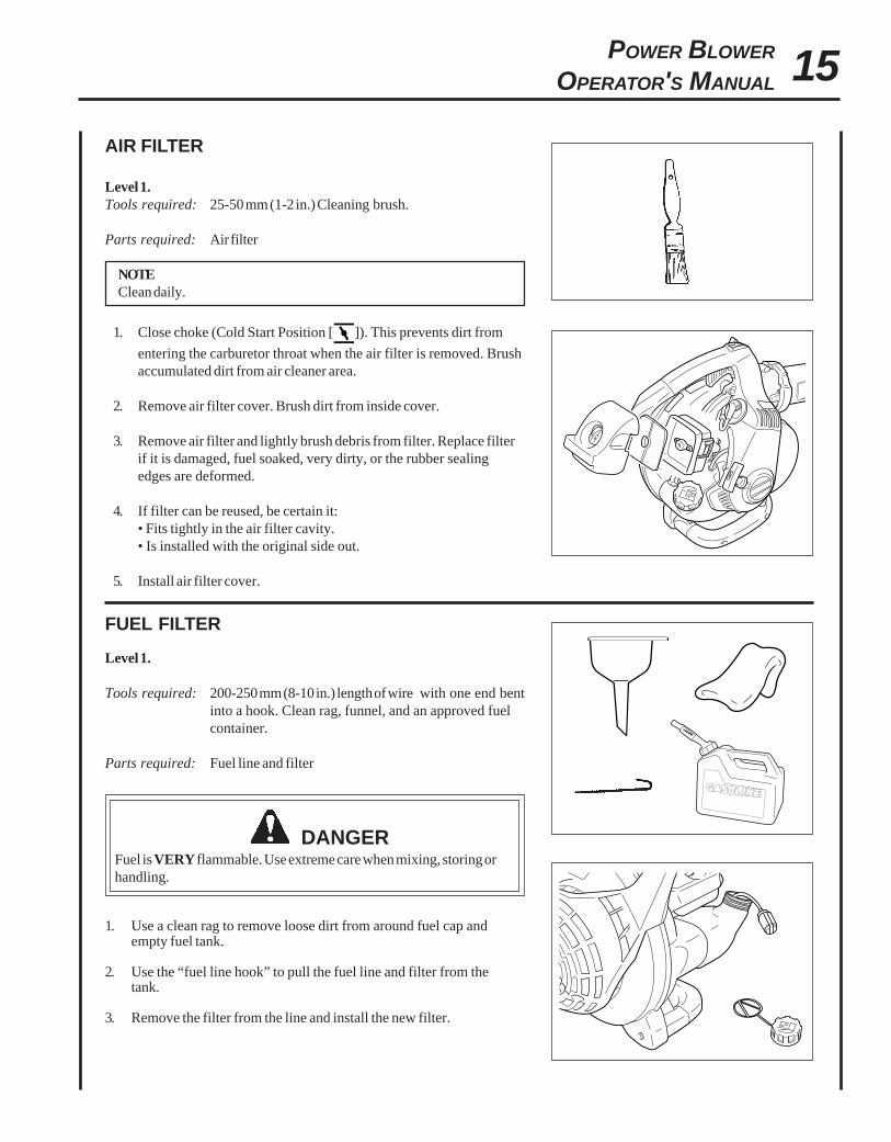
AIR FILTER
Level 1.Tools required: 25-50 mm (1-2 in.) Cleaning brush.
Parts required: Air filter
NOTEClean daily.
1. Close choke (Cold Start Position [ ]). This prevents dirt from
entering the carburetor throat when the air filter is removed. Brushaccumulated dirt from air cleaner area.
2. Remove air filter cover. Brush dirt from inside cover.
3. Remove air filter and lightly brush debris from filter. Replace filterif it is damaged, fuel soaked, very dirty, or the rubber sealingedges are deformed.
4. If filter can be reused, be certain it:• Fits tightly in the air filter cavity.• Is installed with the original side out.
5. Install air filter cover.
FUEL FILTER
Level 1.
Tools required: 200-250 mm (8-10 in.) length of wire with one end bentinto a hook. Clean rag, funnel, and an approved fuelcontainer.
Parts required: Fuel line and filter
DANGERFuel is VERY flammable. Use extreme care when mixing, storing orhandling.
1. Use a clean rag to remove loose dirt from around fuel cap andempty fuel tank.
2. Use the “fuel line hook” to pull the fuel line and filter from thetank.
3. Remove the filter from the line and install the new filter.
16
0.65 mm(0.026 in.)
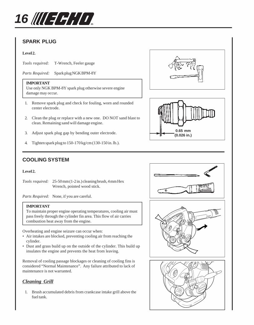
COOLING SYSTEM
Level 2.
Tools required: 25-50 mm (1-2 in.) cleaning brush, 4 mm HexWrench, pointed wood stick.
Parts Required: None, if you are careful.
IMPORTANTTo maintain proper engine operating temperatures, cooling air mustpass freely through the cylinder fin area. This flow of air carriescombustion heat away from the engine.
Overheating and engine seizure can occur when:• Air intakes are blocked, preventing cooling air from reaching the
cylinder.• Dust and grass build up on the outside of the cylinder. This build up
insulates the engine and prevents the heat from leaving.
Removal of cooling passage blockages or cleaning of cooling fins isconsidered “Normal Maintenance”. Any failure attributed to lack ofmaintenance is not warranted.
Cleaning Grill
1. Brush accumulated debris from crankcase intake grill above thefuel tank.
SPARK PLUG
Level 2.
Tools required: T-Wrench, Feeler gauge
Parts Required: Spark plug NGK BPM-8Y
IMPORTANTUse only NGK BPM-8Y spark plug otherwise severe enginedamage may occur.
1. Remove spark plug and check for fouling, worn and roundedcenter electrode.
2. Clean the plug or replace with a new one. DO NOT sand blast toclean. Remaining sand will damage engine.
3. Adjust spark plug gap by bending outer electrode.
4. Tighten spark plug to 150-170 kg/cm (130-150 in. lb.).
17POWER BLOWER
OPERATOR'S MANUAL
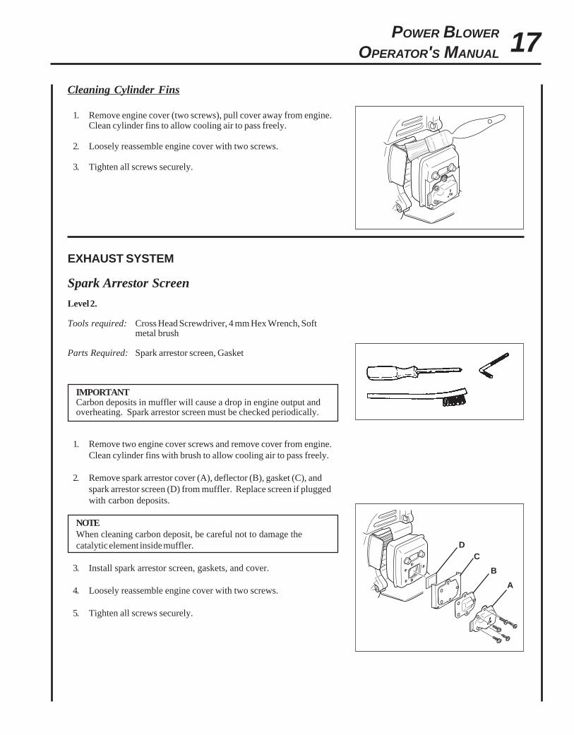
Cleaning Cylinder Fins
1. Remove engine cover (two screws), pull cover away from engine.Clean cylinder fins to allow cooling air to pass freely.
2. Loosely reassemble engine cover with two screws.
3. Tighten all screws securely.
EXHAUST SYSTEM
Spark Arrestor Screen
Level 2.
Tools required: Cross Head Screwdriver, 4 mm Hex Wrench, Softmetal brush
Parts Required: Spark arrestor screen, Gasket
IMPORTANTCarbon deposits in muffler will cause a drop in engine output andoverheating. Spark arrestor screen must be checked periodically.
1. Remove two engine cover screws and remove cover from engine.Clean cylinder fins with brush to allow cooling air to pass freely.
2. Remove spark arrestor cover (A), deflector (B), gasket (C), andspark arrestor screen (D) from muffler. Replace screen if pluggedwith carbon deposits.
NOTEWhen cleaning carbon deposit, be careful not to damage thecatalytic element inside muffler.
3. Install spark arrestor screen, gaskets, and cover.
4. Loosely reassemble engine cover with two screws.
5. Tighten all screws securely.
A
B
DC
18
CARBURETOR ADJUSTMENTEngine Break-InNew engines must be operated a minimum duration of two tanks of fuelbreak-in before carburetor adjustments can be made. During the break-inperiod your engine performance will increase and exhaust emissions willstabilize. Idle speed can be adjusted as required.
High Altitude AdjustmentHigh altitude adjustment is not required for proper operation of thisengine.
Level 2.
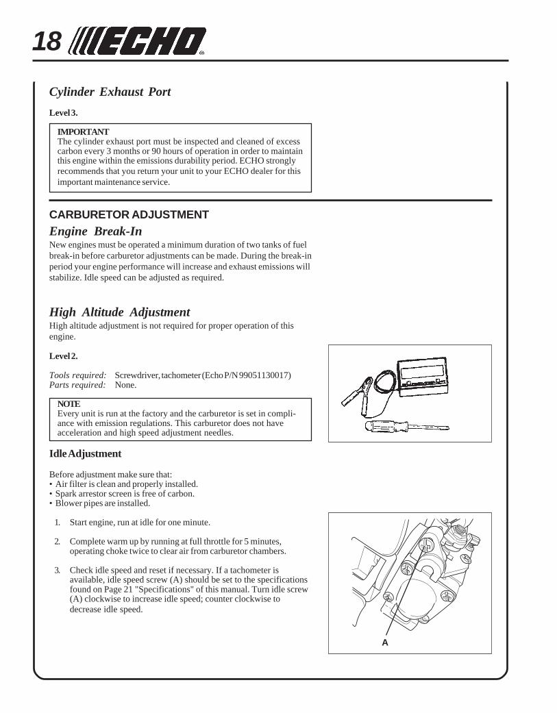
Tools required: Screwdriver, tachometer (Echo P/N 99051130017)Parts required: None.
NOTEEvery unit is run at the factory and the carburetor is set in compli-ance with emission regulations. This carburetor does not haveacceleration and high speed adjustment needles.
Idle Adjustment
Before adjustment make sure that:• Air filter is clean and properly installed.• Spark arrestor screen is free of carbon.• Blower pipes are installed.
1. Start engine, run at idle for one minute.
2. Complete warm up by running at full throttle for 5 minutes,operating choke twice to clear air from carburetor chambers.
3. Check idle speed and reset if necessary. If a tachometer isavailable, idle speed screw (A) should be set to the specificationsfound on Page 21 "Specifications" of this manual. Turn idle screw(A) clockwise to increase idle speed; counter clockwise todecrease idle speed.
Cylinder Exhaust Port
Level 3.
IMPORTANTThe cylinder exhaust port must be inspected and cleaned of excesscarbon every 3 months or 90 hours of operation in order to maintainthis engine within the emissions durability period. ECHO stronglyrecommends that you return your unit to your ECHO dealer for thisimportant maintenance service.
A
19POWER BLOWER
OPERATOR'S MANUAL
TROUBLESHOOTING
TRAHCGNITOOHSELBUORT
melborP kcehC sutatS esuaC ydemeR
-sknarcenignE/drahstrats
t'nseodtrats
roterubractaleuF roterubractaleufoN deggolcreniartsleuFdeggolcenilleuF
roterubraC
ecalperronaelCecalperronaelC
relaedohcEruoyeeS
rednilyctaleuF rednilyctaleufoN roterubraC relaedohcEruoyeeS
leufhtiwtewrelffuM hcirooterutxiMleuF ekohcnepOretlifriaecalper/naelC
roterubractsujdArelaedohcEruoyeeS
dnetakrapSeriwgulpfo
krapsoN ffohctiwspotSmelborplacirtcelE
hctiwskcolretnI
NOothctiwsnruTrelaedohcEruoyeeSrelaedohcEruoyeeS
gulptakrapS krapsoN tcerrocnipagkrapSnobrachtiwderevoC
leufhtiwdeluoFevitcefedgulP
).ni620.0(mm56.ottsujdAecalperronaelCecalperronaelC
gulpecalpeR
,snurenignEroseidtubtonseodetareleccaylreporp
retlifriA ytridretlifriA raewlamroN ecalperronaelC
retlifleuF ytridretlifleuF seudiser/stnanimatnoC nileuf
ecalpeR
tnevleuF deggulptnevleuF leufniseudiser/stnanimatnoC ecalperronaelC
gulPkrapS nrow/ytridgulP raewlamroN ecalperrotsujdadnanaelC
roterubraC tnemtsujdareporpmI noitarbiV tsujdA
metsySgnilooC metsysgnilooCdeggulp/ytrid
ninoitarepodednetxEsnoitacolytsud/ytrid
naelC
neercSrotserrAkrapS neercsrotserrakrapSdeggulp
raewlamroN ecalpeR
seodenignEknarcton
A/N A/N melborpenignelanretnI relaedohcEruoyeeS
,snurenignEt'nseodrewolb
sirokrownevenu/kaew
epiprewolB deggolcepiP sirbedfopu-dliuB golcnU
esoolepiP noitarbiV nethgiT
degamadepiP esusiM/raeW ecalpeR
WARNINGFuel vapors are extremely flammable and may cause fire and/or explosion. Never test for ignition spark by groundingspark plug near cylinder plug hole, otherwise serious personal injury may result.
20
STORAGE
WARNINGDuring operation the muffler or catalytic muffler and surrounding cover becomes hot. Always keep exhaust areaclear of flammable debris during transportation or when storing, otherwise serious property damage or personalinjury may result.
Long Term Storage (Over 30 Days)
Do not store your unit for a prolonged period of time (30 days or longer) without performing protective storage mainte-nance which includes the following:
1. Store unit in a dry, dust free place, out of the reach of children.
WARNINGDo not store where fuel fumes may accumulate or reach an open flame or spark.
2. Place the stop switchs in the "STOP" position.
3. Remove accumulation of grease, oil, dirt and debrisfrom exterior of unit.
4. Perform all periodic lubrication and services that arerequired.
5. Tighten all screws and nuts.
6. Drain the fuel tank completely and pull the recoilstarter handle several times to remove fuel from thecarburetor.
7. Remove the spark plug and pour 7cc (1/4 oz.) offresh, clean ECHO 2-stroke engine oil into thecylinder through the spark plug hole.
A. Place a clean cloth over the spark plug hole.
B. Pull the recoil starter handle 2-3 times todistribute the oil inside the engine.
C. Observe the piston location through the sparkplug hole. Pull the recoil handle slowly until thepiston reaches the top of its travel and leave itthere.
8. Install the spark plug (do not connect ignitioncable).
9. Remove blower pipe assembly from unit.
21POWER BLOWER
OPERATOR'S MANUAL
SPECIFICATIONS
MODEL ----------------------------------------------------- PB-251 Hand Held
Length ------------------------------------------------------- 330 mm (13.0 in.) (w/o pipes)
Width -------------------------------------------------------- 265 mm (10.4 in.)
Height ------------------------------------------------------- 360 mm (14.2 in.)
Weight (dry) ------------------------------------------------ 4.1 kg (9.11 lb.)
Engine Type ------------------------------------------------ Air cooled, two-stroke, single cylinder gasoline engine
Displacement ----------------------------------------------- 25.4cc (1.55 cu. in.)
Bore ---------------------------------------------------------- 34.0 mm (1.34 in.)
Stroke -------------------------------------------------------- 28.0 mm (1.10 in.)
Carburetor -------------------------------------------------- Zama Diaphragm model w/primer bulb
Ignition System -------------------------------------------- Flywheel Magneto, capacitor discharge ignition type
Spark Plug -------------------------------------------------- NGK BPM8Y Gap 0.65 mm (0.026 in.)
Exhaust System -------------------------------------------- Spark Arrestor Muffler w / Catayst
Fuel ---------------------------------------------------------- Mixed (Gasoline and Two-stroke Oil)
Fuel/Oil Ratio ----------------------------------------------- 50:1 two-stroke air cooled engine oil
Gasoline ----------------------------------------------------- 89 Octane unleaded. DO NOT use fuel containing methyl alcohol,
more than 10% ethyl alcohol or 15% MTBE.
Oil ------------------------------------------------------------ Power Blend TM Premium Universal 2-Stroke oil
Fuel Tank Capacity ---------------------------------------- 0.5 lit. (16.9 US fl. oz.)
Recoil Starter System -------------------------------------- Automatic Recoil Starter Centrifugal Type
Idle Speed (RPM) ------------------------------------------ 2,700 - 3,300
Wide Open Throttle Speed (RPM) ----------------------- 6,700 - 7,200
Maximum Air Speed w/pipes (MPH) -------------------- 63.5 m/sec (142 mph)
Maximum Air Volume -------------------------------------- 10.9 m3/min. (386 cu. ft./min.)
Sound Level at 50 ft. dB(A) scale per ANSI B175.2 ---- 65 dB(A)

22
NOTES

23POWER BLOWER
OPERATOR'S MANUAL
NOTES
DEALER?Call
1-800-432-ECHOor
www.echo-usa.com
CONSUMER PRODUCTSUPPORT
1-800-673-15588:30 - 4:30 Mon - Fri C.S.T.
SERVICING INFORMATION
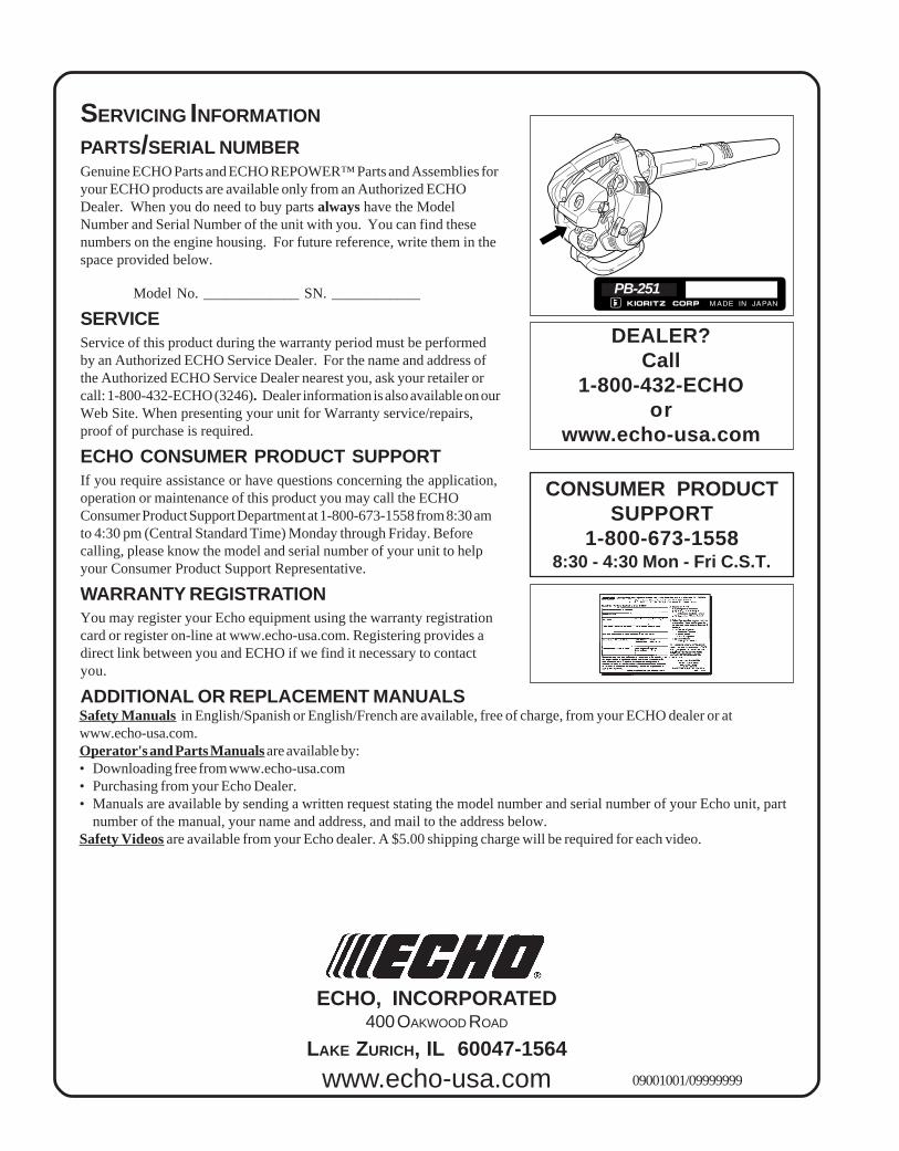
PARTS/SERIAL NUMBERGenuine ECHO Parts and ECHO REPOWER™ Parts and Assemblies foryour ECHO products are available only from an Authorized ECHODealer. When you do need to buy parts always have the ModelNumber and Serial Number of the unit with you. You can find thesenumbers on the engine housing. For future reference, write them in thespace provided below.
Model No. _____________ SN. ____________
SERVICEService of this product during the warranty period must be performedby an Authorized ECHO Service Dealer. For the name and address ofthe Authorized ECHO Service Dealer nearest you, ask your retailer orcall: 1-800-432-ECHO (3246). Dealer information is also available on ourWeb Site. When presenting your unit for Warranty service/repairs,proof of purchase is required.
ECHO CONSUMER PRODUCT SUPPORTIf you require assistance or have questions concerning the application,operation or maintenance of this product you may call the ECHOConsumer Product Support Department at 1-800-673-1558 from 8:30 amto 4:30 pm (Central Standard Time) Monday through Friday. Beforecalling, please know the model and serial number of your unit to helpyour Consumer Product Support Representative.
WARRANTY REGISTRATIONYou may register your Echo equipment using the warranty registrationcard or register on-line at www.echo-usa.com. Registering provides adirect link between you and ECHO if we find it necessary to contactyou.
ADDITIONAL OR REPLACEMENT MANUALSSafety Manuals in English/Spanish or English/French are available, free of charge, from your ECHO dealer or atwww.echo-usa.com.Operator's and Parts Manuals are available by:• Downloading free from www.echo-usa.com• Purchasing from your Echo Dealer.• Manuals are available by sending a written request stating the model number and serial number of your Echo unit, part
number of the manual, your name and address, and mail to the address below.Safety Videos are available from your Echo dealer. A $5.00 shipping charge will be required for each video.
ECHO, INCORPORATED400 OAKWOOD ROAD
LAKE ZURICH, IL 60047-1564
www.echo-usa.com 09001001/09999999
PB-251