Operator's Manual MAGNUM PRO AL G225A/G450W
31
Operator's Manual MAGNUM ® PRO AL W Rear Trigger Front Trigger Register your machine: www. linco In elecic. com/register For use with machines having Code Numbers: K3355-[] K3356-[] K3357-[] K3358-[] K3420-[] K3421-[] K3422-[] K3423-[] Authorized Service and Distributor Locator: www. linco In elecic. com/locator Save for future reference Date Purchased Code: (ex: 10859) Serial: (ex: U1060512345) IM10168-F I lssueDateNov-18 © Lincoln Global, Inc. All Rights Reserved. THE LINCOLN ELECTRIC COMPANY 22801 St. Clair Avenue • Cleveland, OH • 44117-1199 • U.S.A. Phone: +1.216.481.8100 • .lincolnelectric.com
Transcript of Operator's Manual MAGNUM PRO AL G225A/G450W

Operator's Manual
MAGNUM®
PRO AL G225A/G450W
Rear Trigger
Front Trigger
Register your machine:
www. linco In electric. com/register
For use with machines having Code Numbers:
K3355-[]
K3356-[]
K3357-[]
K3358-[]
K3420-[]
K3421-[]
K3422-[]
K3423-[]
Authorized Service and Distributor Locator:
www. linco In electric. com/locator
Save for future reference
Date Purchased
Code: (ex: 10859)
Serial: (ex: U1060512345)
IM10168-F I lssueDateNov-18
© Lincoln Global, Inc. All Rights Reserved.
THE LINCOLN ELECTRIC COMPANY
22801 St. Clair Avenue • Cleveland, OH • 44117-1199 • U.S.A. Phone: + 1.216.481.8100 • www.lincolnelectric.com

SPECIAL SITUATIONS
3
SAFETY

4
SAFETY
5
SAFETY
Get the free mobile app at
http://gettag.org

NOTES

7
TABLE OF CONTENTSMAGNUM® PRO AL Gun
PageInstallation ...........................................................................................................................Section A
Technical Specifications .......................................................................................................... A-1 Support Equipment Required............................................................................................ A-2Installation Instructions ............................................................................................................ A-3 Gun Lead Connections...................................................................................................... A-3 Coolant Connections ......................................................................................................... A-3 Gun Tube Removal/Installation ......................................................................................... A-3 Lead Assy Spiral Wrap Installation .................................................................................... A-4Calibration ............................................................................................................................... A-5
Operation ............................................................................................................................ Section BGeneral Description................................................................................................................. B-1Controls and Settings .............................................................................................................. B-1 Poentiometer ..................................................................................................................... B-1 Micro Switch ...................................................................................................................... B-1 Trigger Sensitivity .............................................................................................................. B-1 Sensitivity Adjustment ....................................................................................................... B-1Drive Roll and Idler Rolls ......................................................................................................... B-1 Drive Roll Installation and Removal .................................................................................. B-1 Idler Roll Installation and Removal .................................................................................... B-1
General Options/Accessories .......................................................................................... Section CCable Covers...........................................................................................................................C-1
Maintenance ....................................................................................................................... Section DRecommended Spare Parts List ............................................................................................. D-1
Troubleshooting .................................................................................................................Section EHow to Use Troubleshooting Guide......................................................................................... E-1Troubleshooting Guide ............................................................................................................ E-2
Diagrams .............................................................................................................................Section FDiagrams / Parts List ................................................................................................................F-1Electrical .................................................................................................................................F-10
A - 1
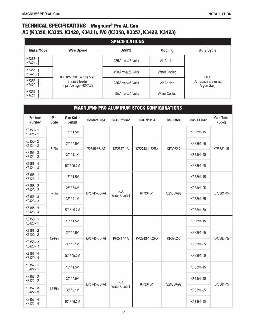
TECHNICAL SPECIFICATIONS - Magnum® Pro AL Gun AC (K3356, K3355, K3420, K3421), WC (K3358, K3357, K3422, K3423)
SPECIFICATIONS
Make/Model Wire Speed AMPS Cooling Duty Cycle
K3356 - [ ] K3421 - [ ]
800 IPM (20.3 mpm) Max. at rated feeder
Input Voltage (42VAC)
225 Amps/25 Volts Air Cooled
60% (All ratings are using
Argon Gas)
K3358 - [ ] K3423 - [ ] 450 Amps/25 Volts Water Cooled
K3355 - [ ] K3420 - [ ] 225 Amps/25 Volts Air Cooled
K3357 - [ ] K3422 - [ ] 450 Amps/25 Volts Water Cooled
INSTALLATIONMAGNUM® PRO AL Gun
MAGNUM® PRO ALUMINUM STOCK CONFIGURATIONS
Product Number
Pin Style
Gun Cable Length Contact Tips Gas Diffuser Gas Nozzle Insulator Cable Liner Gun Tube
45deg
K3356 - 1 K3421 - 1
7-Pin
15' / 4.5M
P2745-364AT KP2747-1A KP2743-1-62RA KP3982-2
KP3391-15
KP3380-45
K3356 - 2 K3421 - 2 25' / 7.6M KP3391-25
K3356 - 3 K3421 - 3 35' / 9.1M KP3391-35
K3356 - 4 K3421 - 4 50' / 15.2M KP3391-50
K3358 - 1 K3423 - 1
7-Pin
15' / 4.5M
KP2745-364AT N/A Water Cooled KP3375-1 S29830-92
KP3391-15
KP3381-45
K3358 - 2 K3423 - 2 25' / 7.6M KP3391-25
K3358 - 3 K3423 - 3 35' / 9.1M KP3391-35
K3358 - 4 K3423 - 4 50' / 15.2M KP3391-50
K3355- 1 K3420 - 1
12-Pin
15' / 4.5M
KP2745-364AT KP2747-1A KP2743-1-62RA KP3982-2
KP3391-15
KP3380-45
K3355 - 2 K3420 - 2 25' / 7.6M KP3391-25
K3355 - 3 K3420 - 3 35' / 9.1M KP3391-35
K3355 - 4 K3420 - 4 50' / 15.2M KP3391-50
K3357 - 1 K3422 - 1
12-Pin
15' / 4.5M
KP2745-364AT N/A Water Cooled KP3375-1 S29830-92
KP3391-15
KP3381-45
K3357 - 2 K3422 - 2 25' / 7.6M KP3391-25
K3357 - 3 K3422 - 3 35' / 9.1M KP3391-35
K3357 - 4 K3422 - 4 50' / 15.2M KP3391-50

A - 2
INSTALLATIONMAGNUM® PRO AL Gun
WIRE CAPACITY
.030 - 1/16" (0.8mm - 1.6mm) aluminum and cored wire
SUPPORT EQUIPMENT REQUIRED• C.V. or C.C. Power Source of sufficient capacity for your needs.• Regulated gas supply and hoses.• Properly sized power leads from power source to wire feeder and ground.• Water source and hose capable of providing a minimum of 1 quart (.95 liter) / min.
at 45 p.s.i. when using water cooled guns.

A - 3
INSTALLATIONMAGNUM® PRO AL Gun
GUN LEAD CONNECTIONSPOWER CABLEAir CooledA #2 power cable is used on the Lincoln Electric Magnum® Pro AL Gun. • The gun end of the power cable is secured into the gun body
with a set screw, and the power pin end is threaded into the gun body.
• These connections utilize a conductive sealant and are tightened with torque requirements of 100 + 5 IN-LB.
Water Cooled• Lincoln Electric Magnum® Pro AL Gun water cooled gun
utilizes a power/water cable with a #6 AWG cable inside a 5/16” diameter hose.
• When water is used with this cable and the #10 water cooled gas nozzle (P/N KP3375-1), the system is rated at 450 amps @ 60% duty cycle.
• The gun end is threaded into the gun body.• These connections utilize a conductive sealant and are
tightened with torque requirements of 100 + 5 IN-LB. CONDUIT• The Lincoln Electric Magnum® Pro AL Gun comes standard
with a poly-lined conduit, for feeding aluminum wire.• The longer fitting with a shallow groove is used on the gun
end.• Both ends of the conduit are secured into the Power Pin
connector with a set screw.GAS HOSE• The BLACK gas hose is pushed over a barbed fitting on the
end of the gun body and secured by twisting the hose retainer to the end of the hose (shown below).
• The opposite end of the BLACK hose is pushed over a barbed fitting in the Power Pin.
• The hose retainer is re-usable and can be removed and re-installed as needed.
CONTROL CABLE
• A multi-conductor control cable is used on the Lincoln Electric Magnum® Pro AL Gun 7 and 12 pin.
COOLANT CONNECTIONS• The ends of the coolant hose push over a barbed fitting on
the end of the rear connector and are secured by twisting the hose retainer to the end of the hose.
• The hose retainer is re-usable and can be removed and re-installed as needed.
• The BLUE coolant supply hose pushes over a barbed fitting and is secured by twisting the hose retainer to the end of the hose.
• The opposite end of the BLUE hose pushes into a threaded coolant fitting.
• The RED coolant return hose pushes over the barbed fitting in the Power Manifold.
• The opposite end of the RED hose pushes into a threaded return hose of the coolant recirculator.
• Both threaded fittings on the end of the BLUE and RED hoses are standard left-hand thread.
COOLANT REQUIREMENTSWARNING: Use Magnum Pro AL Coolant only - failure to usecoolant will void warranty.• Coolant is available in quantities of 1 gallon, 5 gallon (P/N
KP3379-5), or a case of 4 gallons each (P/N KP3379-4).• The coolant flow rate should be a minimum of 10 GPH (1 qt/min) between 35 and 45psi.• Contact the re-circulator manufacturer for specifications on pressure.
GUN TUBE REMOVAL/INSTALLATIONWARNING: Do not attempt to weld without the gun tube being tightly secured in the gun body, or damage to the gun tube or body may result.
a. To remove the gun tube assembly, loosen the taper lock nut until it is clear of the threads. Pull gun tube out of the gun body.
b. To replace a gun tube assembly, open the drive and idler roll door and seat the gun tube assembly until the plastic liner is almost touching the drive and idler roll (Figure 1) and the rear copper face of the gun tube is flush with the aluminum body block (Figure 2).
c. Take care not to damage the “O” rings when inserting into the body. You should hear an audible "click" when the gun tube is inserted and seated.
d. Tighten taper lock nut assembly firmly so that gun tube cannot rotate.
Gun Tube Rotationa. To rotate a gun tube assembly, loosen the taper lock nut
assembly no more than 1 turn. b. Rotate gun tube to the position of your choice and retighten taper
lock nut assembly firmly so that the gun tube cannot rotate.
LEAD ASSY SPIRAL WRAP
S29830-97* Left-Hand Threaded Fitting
*Must be ordered together
S29830-145/16” Hose Retainer
S29830-96* Nipple
Copper face of gun tube
Plastic linerFigure 2Figure 1

A - 4
INSTALLATIONMAGNUM® PRO AL Gun
INSTALLATIONGUN END, AIR COOLED
Conduit Spiral Wrap p/n: S29830-94
Power Cable
Spiral Wrap
Conduit

P.50 AUTO CALIBRATION PROCEDURE
A - 5
CALIBRATIONMAGNUM® PRO AL Gun
The auto calibration procedure is used to provide an automatic means of configuring the pull gun to operatewith the optimal setting of Gun Offset (P.7 in the user preference menu).
Before running the auto calibration procedure, make sure that the system is set up and ready for welding. P.24 must also be set for the correct pull gun type prior to running auto calibration.
To begin the auto calibration procedure, select P.50 from the user preferences menu. Press the “Begin” button to start the calibration. Pull the gun trigger and hold it closed throughout the procedure. Wire will feed out of the gun while the calibration is being performed. The welding output is NOT energized during the auto calibration procedure. The prompts on the display will indicate when the calibration is complete. If the calibration is interrupted or fails, the procedure should be repeated.
Auto calibration should be performed whenever the wire or gun is changed.
Press both soft keys simultaneously to get into the user settings
(Figure 6).
Scroll to setting P7 using the dial (Figure 7).
Press the adj soft key to adjust the setting (Figure 8).
Figure 6
Figure 7
Figure 8
B - 1
OPERATIONMAGNUM® PRO AL Gun
GENERAL DESCRIPTIONThe Lincoln Electric Magnum® Pro AL Gun maintains a constant, steady, uniform wire feed speed. The constant push exerted by the motor in the cabinet, combined with the pull of the gun motor, causes the wire to literally float friction-free through the wire conduit. The 24VDC gun motor is controlled by a three and three-quarter (3 3/4) turn potentiometer in the gun handle.
CONTROLS AND SETTINGS
Potentiometer:• The laterally-positioned potentiometer is located in the gun
body, providing up to 800 ipm with 3 3/4 turns.Micro Switch:• The micro switch assembly consists of the micro switch, and
leads. Trigger Sensitivity:• The amount of trigger level travel can be shortened for a
"quicker" or "more responsive" action. • A more sensitive trigger lever is produced by reducing the
gap between the trigger lever and the micro switch lever. • By turning-in the Trigger Sensitivity Adjustment Screw, it
closes the gap between the trigger lever and the micro switch lever - this enables the operator to increase the sensitivity of the trigger lever.
Sensitivity Adjustment:• With the wire feeder turned on (with or without welding wire
loaded), turn the screw in until the micro switch is activated. • Once activated, the gun and wire feeder motors will begin
feeding wire. • Retract the screw accordingly until the system is deactivated
and adjusted to the operators' liking.
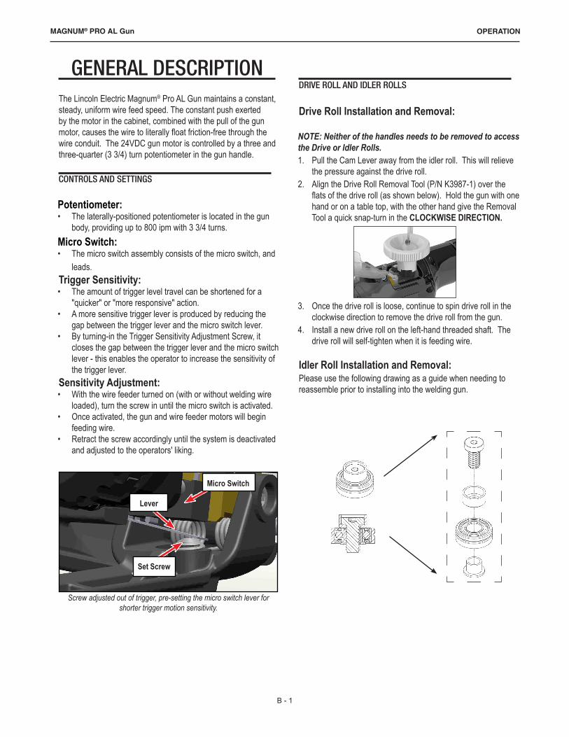
DRIVE ROLL AND IDLER ROLLS
Drive Roll Installation and Removal:
NOTE: Neither of the handles needs to be removed to access the Drive or Idler Rolls. 1. Pull the Cam Lever away from the idler roll. This will relieve
the pressure against the drive roll.2. Align the Drive Roll Removal Tool (P/N K3987-1) over the
flats of the drive roll (as shown below). Hold the gun with one hand or on a table top, with the other hand give the Removal Tool a quick snap-turn in the CLOCKWISE DIRECTION.
3. Once the drive roll is loose, continue to spin drive roll in the clockwise direction to remove the drive roll from the gun.
4. Install a new drive roll on the left-hand threaded shaft. The drive roll will self-tighten when it is feeding wire.
Idler Roll Installation and Removal:Please use the following drawing as a guide when needing to reassemble prior to installing into the welding gun.
Screw adjusted out of trigger, pre-setting the micro switch lever for shorter trigger motion sensitivity.
Set Screw
Lever
Micro Switch

C - 1
ACCESSORIESMAGNUM® PRO AL Gun
GENERAL OPTIONS/ ACCESSORIES
KP3989-1 Insulated Groove Drive Roll Kit - For .035" (0.9mm) dia. and .040" (1.0mm) dia. aluminum wire. Includes insulated groove drive roll and insulated idler roll assy.
KP3989-2 Insulated Groove Drive Roll Kit - For 3/64" (1.2mm) dia. and .062" (1.6mm) dia.aluminum wire. Includes insulated groove drive roll and insulated idler roll assy.
Cable Covers:Cable covers are standard on all guns. You may order spare replacement covers to protect the lead assy of the gun when the factory one becomes damaged or worn. It can easily be replaced in the field by means of Velcro©.KP3378-15 Cable Cover (for 15 ft leads)KP3378-25 Cable Cover (for 25 ft leads)KP3378-35 Cable Cover (for 35 ft leads)KP3378-50 Cable Cover (for 50 ft leads)
GUN TUBE ASSEMBLIES
Air Cooled• Air cooled guns come standard with a 45° curved gun tube
(P/N KP3380-45). • The gun tube assembly locks to the gun body using a taper
lock system.
Water Cooled• Water cooled gun comes standard with a 45° curved water
cooled gun tube assembly (P/N KP3381-45)
Optional 6" Gun Tube AssembliesAir Cooled & Water Cooled (Replaceable diffuser) KP3380-180 – Straight KP3380-45 – 45° (Standard on Air Cooled) KP3380-60 – 60°Air Cooled & Water Cooled (Fixed diffuser) KP3988-180 - Straight KP3988-45 – 45° KP3988-60 – 60°Water Cooled Only (Fixed diffuser & Water Cooled Nozzle) KP3381-180 – Straight KP3381-45 – 45° (Standard on Water Cooled) KP3381-60 – 60°

D - 1
MAINTENANCEMAGNUM® PRO AL Gun
INSULATED IDLER ROLL KP3992-364 (3/64 Wire) KP3992-035 (0.035 Wire) KP3992-116 (1/16 Wire)
MAINTENANCE COMPONENTS
Recommended Spare Parts ListDESCRIPTION PART NO. FOR
K3355, K3356, K3357, K3358
PART NO. FOR K3420, K3421, K3422, K3423
Conduit Liner -15 ft KP3991-15Conduit Liner - 25 ft KP3991-25Conduit Liner - 35 ft KP3991-35Conduit Liner - 50 ft KP3991-50Door S29830-15Trigger Assy. Kit S29830-48 S29830-112Potentiometer Kit S29830-50Handle Kit S29830-45 S29830-111Micro-Switch Kit S29830-47 S29830-113Drive Roll KP3990-1Drive Roll Removal Tool K3987-1Idler Roll Kit KP3992-1Contact Tip Removal Tool K3986-1O-Ring Kit S29830-83Hardware Kit S29830-51Noalox Kit S29830-52Liner Package Magnum PRO .035-3/64 (5) KP3376-3
Liner Package Magnum PRO 1/16 (5) KP3376-1
KNURLED INSULATED DRIVE ROLLKP3990-1
MICRO SWITCH ASSEMBLYS29830-47 S29830-113
CONTACT TIP REMOVAL TOOL(SHOWN WITH TIP)
K3986-1
DRIVE ROLL REMOVAL TOOLK3987-1
E - 1
TROUBLESHOOTINGMAGNUM® PRO AL Gun

E - 2
TROUBLESHOOTINGMAGNUM® PRO AL Gun
Observe all Safety Guidelines detailed throughout this manualPROBLEMS
(SYMPTOMS)POSSIBLE
CAUSERECOMMENDED
COURSE OF ACTION
No wire feed at gun.
115/42 VAC Control fuse in feeder/Control box blown. Replace fuse.
Micro-switch defective/not being activated. Replace switch. Check switch for operation.Broken electrical cable. Check micro switch wires for continuity.
Wire feeds, but welding wire is not energized.
Loose or no cable connections. Check all power connections.
Welding power source. Check power source.
Wire feeds erratically.Dirty or worn conduit. Replace conduit.Wrong size contact tip. See Contact tip table.Idler roll stuck. Replace if damaged.
Wire feeds one speed only.
Bad potentiometer. Check with meter.
Broken electrical cable. Check potentiometer wires for continuity or short.
Bad speed control. See specific cabinet/control owners manual for speed control operation.
Wire walks out of drive rolls. Idler roll upside-down. Place groove in idler roll toward top.

F - 1
DIAGRAMSMAGNUM® PRO AL Gun
HEAD ASSY DIAGRAM - MAGNUM® PRO AL GUN K3355, K3356, K3357, K3358
Please identify your front body assembly before ordering a replacement part.
If your Front Body Assembly looks like figure 2, you need to also replace the handles when replacing the Front Body Assembly.
If your Front Body Assembly looks like figure 1, identified by the notch in the lower right, you do not need to replace the handles when replacing the front body assembly.

F - 2
DIAGRAMSMAGNUM® PRO AL Gun
HEAD ASSY DIAGRAM - MAGNUM® PRO AL GUN K3355, K3356, K3357, K3358
No. Part No. Description1 S29830-1 Assy Cam Idler Arm2 S29830-6 Front Body Assy, A/W3 S29830-48 Assy Trigger Magnum® Pro AL Gun 4 S29830-50 Kit Assy Pot Magnum® Pro AL Gun 5 S29830-10 Assy Rear Body Magnum® Pro AL Gun 6 S29830-47 Kit Assy Micro Swx Magnum® Pro AL Gun 7 S29830-13 Motor 24VDC, Standard8
included in S29830-51
Scr FH Phil 82 4-40 x 3/8 SST9 Scr FH Phil 82 4-40 5/8 SST
10 Scr Button 4-40 x 3/16 SST 11 Wshr SPR LK #6 SST12 Scr Soc. HD Cap #4-40, SST13 included in S29830-45 Screw SHC 4-40 x 1/2 SST14
included in S29830-51Scr SHC 6-32 x 3/8 SST
15 Scr Soc HD Cap #1-72 x 3/8 LG SST16 For reference only Label17 S29830-98 Handle Decal18 included in S29830-45 Scr Shoulder 1/8, Door MX19 S29830-85 Strap Motor20
included in S29830-45 Kit Handle Magnum® Pro AL Gun : includes item 13, 17, 18 and 222122 S29830-15 Door23 For reference only Heat Shrink Tubing

F - 3
DIAGRAMSMAGNUM® PRO AL Gun
HEAD ASSY DIAGRAM - MAGNUM® PRO AL GUN K3420, K3421, K3422, K3423
No. Part No. Description1 S29830-1 Assy Cam Idler Arm2 S29830-6 Front Body Assy, A/W3 S29830-50 Kit Assy Pot Magnum® Pro AL Gun 4 S29830-10 Assy Rear Body Magnum® Pro AL Gun 5 S29830-112 Assy Trigger Magnum® Pro AL Gun6 S29830-113 Kit Assy Micro Swx Magnum® Pro AL Gun 7 S29830-13 Motor 24VDC, Standard8
included in S29830-51
Scr FH Phil 82 4-40 x 3/8 SST9 Scr FH Phil 82 4-40 5/8 SST
10 Scr Button 4-40 x 3/16 SST 11 Wshr SPR LK #6 SST12 included in S29830-111 Screw SHC 4-40 x 1/2 SST13
included in S29830-51Scr SHC 6-32 x 3/8 SST
14 Scr Soc HD Cap #1-72 x 3/8 LG SST15 For reference only Label16 S29830-98 Handle Decal17 included in S29830-51 Dowel Pin18 included in S29830-111 Scr Shoulder 1/8, Door MX19 S29830-85 Strap Motor20 S29830-15 Door21
included in S29830-111 Kit Handle Magnum® Pro AL Gun : includes item 12, 16, 18 and 202226 For reference only PVC Tubing28 For reference only Heat Shrink Tubing
F - 4
DIAGRAMSMAGNUM® PRO AL Gun
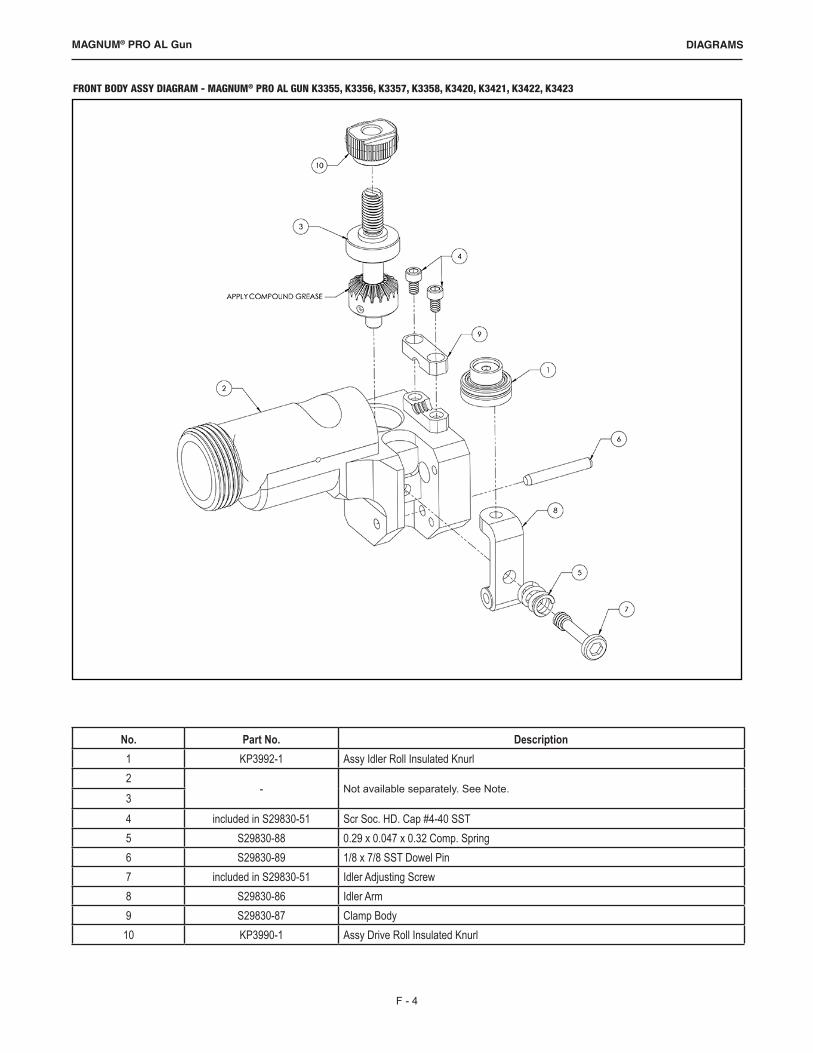
No. Part No. Description1 KP3992-1 Assy Idler Roll Insulated Knurl2
- Not available separately. See Note. 34 included in S29830-51 Scr Soc. HD. Cap #4-40 SST5 S29830-88 0.29 x 0.047 x 0.32 Comp. Spring6 S29830-89 1/8 x 7/8 SST Dowel Pin7 included in S29830-51 Idler Adjusting Screw8 S29830-86 Idler Arm9 S29830-87 Clamp Body
10 KP3990-1 Assy Drive Roll Insulated Knurl
FRONT BODY ASSY DIAGRAM - MAGNUM® PRO AL GUN K3355, K3356, K3357, K3358, K3420, K3421, K3422, K3423
F - 5
DIAGRAMSMAGNUM® PRO AL Gun
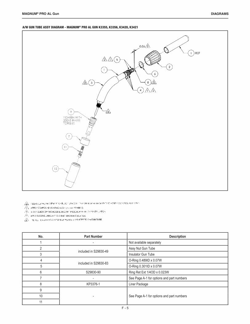
No. Part Number Description1 - Not available separately2
included in S29830-49Assy Nut Gun Tube
3 Insulator Gun Tube 4
included in S29830-83O-Ring 0.489ID x 0.07W
5 O-Ring 0.301ID x 0.07W6 S29830-90 Ring Ret Ext 1/4OD x 0.023W7 - See Page A-1 for options and part numbers8 KP3376-1 Liner Package9
- See Page A-1 for options and part numbers1011
A/W GUN TUBE ASSY DIAGRAM - MAGNUM® PRO AL GUN K3355, K3356, K3420, K3421

F - 6
DIAGRAMSMAGNUM® PRO AL Gun
No. Part No. Description1 - Not available separately2
included in S29830-49Assy Nut Gun Tube
3 Insulator Gun Tube4 S29830-92 Insulator Nozzle with Five O-Rings5
included in S29830-83O-Ring .489 ID x .07 W
6 O-Ring .301 ID x .07 W7 S29830-90 Retaining Ring 5/8 Shaft8 S29830-91 Ring Ret 0.500 Dia Shaft Spiral SST9 - See Page A-1 for options and part numbers
10 S29830-93 Retaining Nut W/C11 KP3376-1 Liner Package12
- See Page A-1 for options and part numbers13
W/C GUN TUBE ASSY DIAGRAM - MAGNUM® PRO AL GUN K3357, K3358, K3422, K3423

F - 7
DIAGRAMSMAGNUM® PRO AL Gun
AIR COOLED LEAD ASSY DIAGRAM - MAGNUM® PRO AL GUN K3355, K3356, K3420, K3421
No. Description 15' Part No. 25' Part No. 35' Part No. 50' Part No.1 Assy Boot Torch S29830-22 Assy Power Manifold, A/W S29830-33 Assy Power Pin Adapter S29830-54 Assy Rear Connector, A/C S29830-95 Wrap Spiral Cord, 13 in S29830-946 Boot Torch S29830-997 Cable Cover KP3378-15 KP3378-25 KP3378-35 KP3378-508 Washer Split Lock 0.27OD x 0.17ID x 0.04 thk included in S29830-519 Screw SHC 4-40 x 1/2 SST included in S29830-46
10 Scr Shc 8-32 x 3/4 SST included in S29830-5111 Labels For reference only1213 Tie Wrap included with item 2614* Tie Wrap Low Prof 14-9/16LG Blk included with item 615 Retainer 5/16 Hose S29830-1416 Swivel Joint Molded S29830-1117 Handle Kit: Includes item 9 S29830-461819 Gas Hose S29830-21 S29830-22 S29830-23 S29830-2420 Conduit Liner KP3991-15 KP3991-25 KP3991-35 KP3991-5021 Assy Teflon Tube Conduit S29830-25 S29830-26 S29830-27 S29830-2822 Heat Shrink Tubing 1/2" Dia x 1" Lg For reference only23 Cap Vinyl Round, Fit 3/16" -1/4" OD x 1/2" LG24 Compound Joint Noalox Kit S29830-5225 - -26 - -27 Assy Power Cable S29830-29 S29830-30 S29830-31 S29830-3228 Assy Controller Cable (Models K3356, K3358, K3421, K3423) S29830-41 S29830-42 S29830-43 S29830-44
Assy Controller Cable (Models K3355, K3357 K3420, K3422) S29830-37 S29830-38 S29830-39 S29830-40* Hose Retainer is re-usable and can be removed and re-installed as needed
F - 8
DIAGRAMSMAGNUM® PRO AL Gun
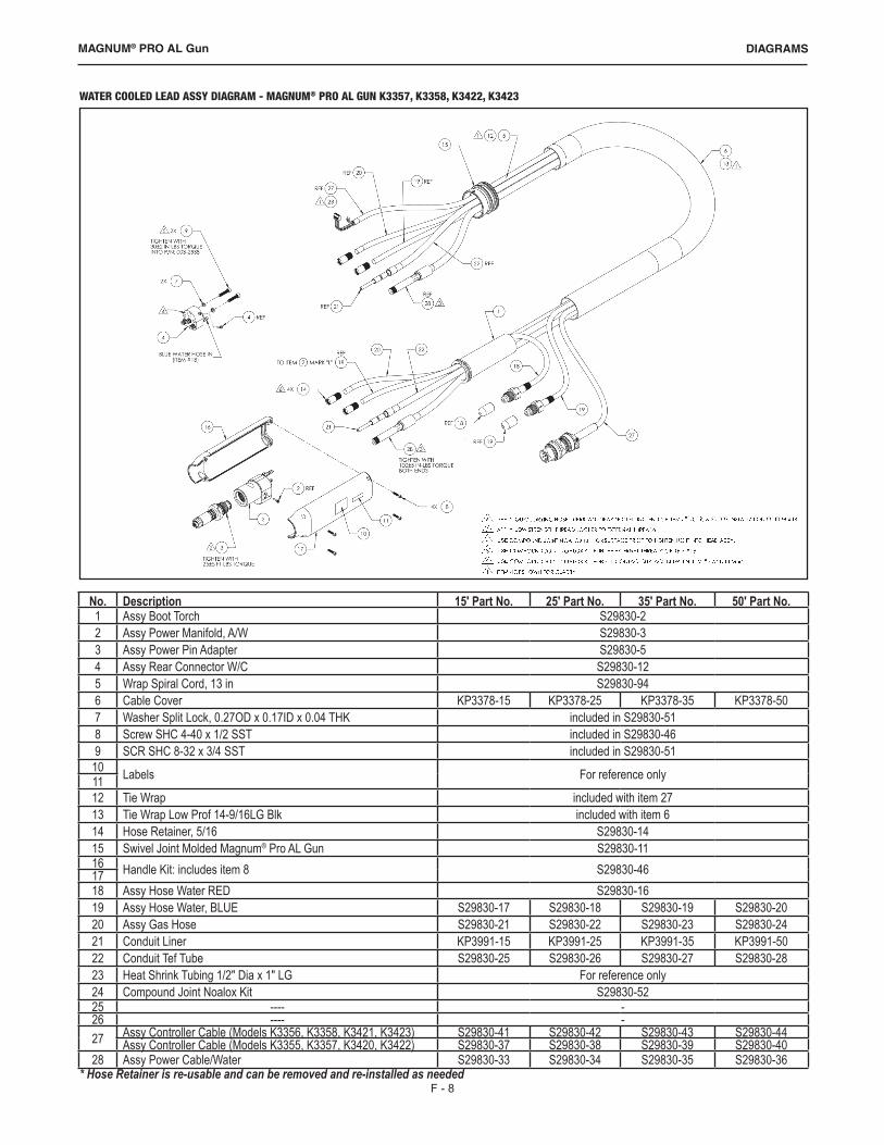
No. Description 15' Part No. 25' Part No. 35' Part No. 50' Part No.1 Assy Boot Torch S29830-22 Assy Power Manifold, A/W S29830-33 Assy Power Pin Adapter S29830-54 Assy Rear Connector W/C S29830-125 Wrap Spiral Cord, 13 in S29830-946 Cable Cover KP3378-15 KP3378-25 KP3378-35 KP3378-507 Washer Split Lock, 0.27OD x 0.17ID x 0.04 THK included in S29830-518 Screw SHC 4-40 x 1/2 SST included in S29830-469 SCR SHC 8-32 x 3/4 SST included in S29830-51
10 Labels For reference only1112 Tie Wrap included with item 2713 Tie Wrap Low Prof 14-9/16LG Blk included with item 614 Hose Retainer, 5/16 S29830-1415 Swivel Joint Molded Magnum® Pro AL Gun S29830-1116 Handle Kit: includes item 8 S29830-461718 Assy Hose Water RED S29830-1619 Assy Hose Water, BLUE S29830-17 S29830-18 S29830-19 S29830-2020 Assy Gas Hose S29830-21 S29830-22 S29830-23 S29830-2421 Conduit Liner KP3991-15 KP3991-25 KP3991-35 KP3991-5022 Conduit Tef Tube S29830-25 S29830-26 S29830-27 S29830-2823 Heat Shrink Tubing 1/2" Dia x 1" LG For reference only24 Compound Joint Noalox Kit S29830-5225 ---- -26 ---- -27 Assy Controller Cable (Models K3356, K3358, K3421, K3423) S29830-41 S29830-42 S29830-43 S29830-44
Assy Controller Cable (Models K3355, K3357, K3420, K3422) S29830-37 S29830-38 S29830-39 S29830-4028 Assy Power Cable/Water S29830-33 S29830-34 S29830-35 S29830-36
WATER COOLED LEAD ASSY DIAGRAM - MAGNUM® PRO AL GUN K3357, K3358, K3422, K3423
* Hose Retainer is re-usable and can be removed and re-installed as needed
F - 9
DIAGRAMSMAGNUM® PRO AL Gun
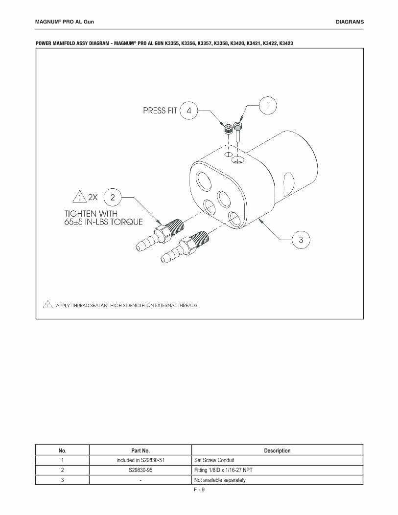
No. Part No. Description1 included in S29830-51 Set Screw Conduit2 S29830-95 Fitting 1/8ID x 1/16-27 NPT3 - Not available separately
POWER MANIFOLD ASSY DIAGRAM - MAGNUM® PRO AL GUN K3355, K3356, K3357, K3358, K3420, K3421, K3422, K3423

F - 10
DIAGRAMSMAGNUM® PRO AL Gun
Models K3356, K3358, K3421 and K3423
Models K3355, K3357, K3420 and K3422

NOTES

F - 12
DIAGRAMSMAGNUM® PRO AL Gun

F - 13
DIAGRAMSMAGNUM® PRO AL Gun