Operator’s Manual IDF Heater HI 900 - Wacker...
162
5200015144 01 1113 5 2 0 0 0 1 5 1 4 4 Operator’s Manual IDF Heater HI 900 EN
Transcript of Operator’s Manual IDF Heater HI 900 - Wacker...

5200015144 01 1113
5 2 0 0 0 1 5 1 4 4
Operator’s Manual
IDF Heater
HI 900
EN

Copyright notice © Copyright 2013 by Wacker Neuson Production Americas LLCAll rights, including copying and distribution rights, are reserved.This publication may be photocopied by the original purchaser of the machine. Any other type of reproduction is prohibited without express written permission from Wacker Neuson Production Americas LLC.Any type of reproduction or distribution not authorized by Wacker Neuson Production Americas LLC represents an infringement of valid copyrights. Violators will be prosecuted.
Trademarks All trademarks referenced in this manual are the property of their respective owners.
Manufacturer Wacker Neuson Production Americas LLCN92W15000 Anthony AvenueMenomonee Falls, WI 53051 U.S.A.Tel: (262) 255-0500 · Fax: (262) 255-0550 · Tel: (800) 770-0957www.wackerneuson.com
Original instructions This Operator’s Manual presents the original instructions. The original language of this Operator’s Manual is American English.

HI 900 Foreword
ForewordHI 900G, HI 900DTHESE HEATERS ARE SUITABLE FOR OUTDOOR OR INDOOR USE. ADEQUATE VENTILATION MUST BE PROVIDED.THIS HEATER IS INTENDED FOR USE PRIMARILY AS TEMPORARY HEATING OF BUILDINGS UNDER CONSTRUCTION, ALTERATION, OR REPAIR.
WARNINGGENERAL HAZARD-FAILURE TO COMPLY WITH THE PRECAUTIONS AND INSTRUCTIONS PROVIDED WITH THIS HEATER, CAN RESULT IN DEATH, SERIOUS BODILY INJURY AND PROPERTY LOSS OR DAMAGE FROM HAZARDS OF FIRE, EXPLOSION, BURN, ASPHYXIATION, CAR-BON MONOXIDE POISONING, AND / OR ELECTRICAL SHOCK.
ONLY PERSONS WHO CAN UNDERSTAND AND FOLLOW THE INSTRUCTIONS SHOULD USE OR SERVICE THIS HEATER.IF YOU NEED ASSISTANCE OR HEATER INFORMATION SUCH AS AN INSTRUCTION MANUAL, LABEL, ETC. CONTACT THE MANUFAC-TURER.
WARNINGWORK SITE FIRE, BURN, INHALATION, AND EXPLOSION HAZARDS.
KEEP SOLID COMBUSTIBLES, SUCH AS BUILDING MATERIALS, PAPER, OR CARDBOARD AT A SAFE DISTANCE AWAY FROM THE MACHINE AS RECOMMENDED BY THE INSTRUCTIONS.NEVER USE THIS MACHINE IN SPACES WHICH DO OR MAY CON-TAIN VOLATILE OR AIRBORNE COMBUSTIBLES, OR PRODUCTS SUCH AS GASOLINE, SOLVENTS, PAINT THINNER, DUST PARTI-CLES, OR UNKNOWN CHEMICALS.
WARNINGNOT FOR HOME OR RECREATIONAL VEHICLE USE.
OPERATE THE MACHINE ONLY FOR APPLICATIONS SPECIFIED IN MACHINE DESCRIPTION AND INTENDED USE.
wc_tx003508gb.fm3

Foreword HI 900
This heater is designed and approved for use as a construction heater in accordance with Standard ANSI Z83.7–CSA 2.14. CHECK WITH YOUR LOCAL FIRE SAFETY AUTHORITY IF YOU HAVE QUESTIONS ABOUT APPLICATIONS.Other standards govern the use of fuel gases and heat producing products in specific applications. Your local authority can advise you about these.THE INSTALLATION OF THE UNIT SHALL BE IN ACCORDANCE WITH THE REGULATIONS OF THE AUTHORITIES HAVING JURISDICTION. In Canada, use the CSA B139 installation code for oil burning equipment.
wc_tx003508gb.fm4

HI 900 Foreword
HI 900DGMTHESE HEATERS ARE SUITABLE FOR OUTDOOR USE ONLY.THIS HEATER IS INTENDED FOR USE PRIMARILY AS TEMPORARY HEATING OF BUILDINGS UNDER CONSTRUCTION, ALTERATION, OR REPAIR.WARNINGGENERAL HAZARD-FAILURE TO COMPLY WITH THE PRECAUTIONS AND INSTRUCTIONS PROVIDED WITH THIS HEATER, CAN RESULT IN DEATH, SERIOUS BODILY INJURY AND PROPERTY LOSS OR DAMAGE FROM HAZARDS OF FIRE, EXPLOSION, BURN, ASPHYXIATION, CAR-BON MONOXIDE POISONING, AND / OR ELECTRICAL SHOCK.
ONLY PERSONS WHO CAN UNDERSTAND AND FOLLOW THE INSTRUCTIONS SHOULD USE OR SERVICE THIS HEATER.IF YOU NEED ASSISTANCE OR HEATER INFORMATION SUCH AS AN INSTRUCTION MANUAL, LABEL, ETC. CONTACT THE MANUFAC-TURER.
WARNINGWORK SITE FIRE, BURN, INHALATION, AND EXPLOSION HAZARDS.
KEEP SOLID COMBUSTIBLES, SUCH AS BUILDING MATERIALS, PAPER, OR CARDBOARD AT A SAFE DISTANCE AWAY FROM THE MACHINE AS RECOMMENDED BY THE INSTRUCTIONS.NEVER USE THIS MACHINE IN SPACES WHICH DO OR MAY CON-TAIN VOLATILE OR AIRBORNE COMBUSTIBLES, OR PRODUCTS SUCH AS GASOLINE, SOLVENTS, PAINT THINNER, DUST PARTI-CLES, OR UNKNOWN CHEMICALS.
WARNINGNOT FOR HOME OR RECREATIONAL VEHICLE USE.
OPERATE THE MACHINE ONLY FOR APPLICATIONS SPECIFIED IN MACHINE DESCRIPTION AND INTENDED USE.
wc_tx003508gb.fm5
Foreword HI 900
This heater is designed and approved for use as a construction heater in accordance with Standard ANSI Z83.7–CSA 2.14. CHECK WITH YOUR LOCAL FIRE SAFETY AUTHORITY IF YOU HAVE QUESTIONS ABOUT APPLICATIONS.Other standards govern the use of fuel gases and heat producing products in specific applications. Your local authority can advise you about these.THE INSTALLATION OF THE UNIT SHALL BE IN ACCORDANCE WITH THE REGULATIONS OF THE AUTHORITIES HAVING JURISDICTION.In Canada, use the CSA B139 installation code for oil burning equipment.
SAVE THESE INSTRUCTIONS—This manual contains important instructions for the machine models below. These instructions have been written expressly by Wacker Neuson Production Americas LLC and must be followed during installation, operation, and maintenance of the machines.
Machines covered by this manual
This manual covers machines with the following item numbers:
Machine Item NumberHI 900D, 2X20 5200014158HI 900D, 3X16 5200014159HI 900D, 4X12 5200014160HI 900G, 2X20 5200014161HI 900G, 3X16 5200014163HI 900G, 4X12 5200014164HI 900DGM, 2X20, EB 5200014165HI 900DGM, 2X20, SB 5200014166
wc_tx003508gb.fm6

HI 900 Foreword
Machine identification
A nameplate listing the model number, item number, revision number, and serial number is attached to this machine. The location of the nameplate is shown above.
Serial number (S/N)
For future reference, record the serial number in the space provided below. You will need the serial number when requesting parts or service for this machine.
Machine documentation
From this point forward in this documentation, Wacker Neuson Production Americas LLC will be referred to as Wacker Neuson.Keep a copy of the Operator’s Manual with the machine at all times. Use the separate Parts Book supplied with the machine to order replacement parts. If you are missing either of these documents, please contact Wacker Neuson to order a replacement or visit www.wackerneuson.com. When ordering parts or requesting service information, be prepared to provide the machine model number, item number, revision number, and serial number.
Expectations for information in this manual
This manual provides information and procedures to safely operate and maintain the above Wacker Neuson model(s). For your own safety and to reduce the risk of injury, carefully read, understand, and observe all instructions described in this manual. Wacker Neuson expressly reserves the right to make technical modifications, even without notice, which improve the performance or safety standards of its machines.The information contained in this manual is based on machines manufactured up until the time of publication. Wacker Neuson reserves the right to change any portion of this information without notice.The illustrations, parts, and procedures in this manual refer to Wacker Neuson factory-installed components. Your machine may vary depending on the requirements of your specific region.
wc_gr011381
Serial Number:
wc_tx003508gb.fm7

Foreword HI 900
CALIFORNIA Proposition 65 WarningCombustion exhaust, some of its constituents, and certain vehicle components contain or emit chemicals known to the State of California to cause cancer and birth defects or other reproductive harm.
Laws pertaining to spark arresters
NOTICE: State Health Safety Codes and Public Resources Codes specify that in certain locations spark arresters be used on internal combustion engines that use hydrocarbon fuels. A spark arrester is a device designed to prevent accidental discharge of sparks or flames from the engine exhaust. Spark arresters are qualified and rated by the United States Forest Service for this purpose. In order to comply with local laws regarding spark arresters, consult the engine distributor or the local Health and Safety Administrator.
Manufacturer’s approval
This manual contains references to approved parts, attachments, and modifications. The following definitions apply:
Approved parts or attachments are those either manufactured or provided by Wacker Neuson. Approved modifications are those performed by an authorized Wacker Neuson service center according to written instructions published by Wacker Neuson.Unapproved parts, attachments, and modifications are those that do not meet the approved criteria.
Unapproved parts, attachments, or modifications may have the following consequences:
Serious injury hazards to the operator and persons in the work areaPermanent damage to the machine which will not be covered under warranty
Contact your Wacker Neuson dealer immediately if you have questions about approved or unapproved parts, attachments, or modifications.
wc_tx003508gb.fm8

Table of ContentsHI 900
Foreword 3
1 Safety Information 13
1.1 Signal Words Used in this Manual ..................................................... 131.2 Machine Description and Intended Use ............................................. 141.3 Operating Safety ................................................................................ 151.4 Safety Guidelines for Operating Combustion Burners ....................... 161.5 Service Safety .................................................................................... 181.6 Safety Guidelines for Operating Gensets ........................................... 201.7 Safety Guidelines for Towing the Machine ......................................... 221.8 Safety Guidelines for Lifting and Transporting the Machine ............... 231.9 Reporting Safety Defects ................................................................... 23
2 Labels 24
2.1 Label Locations .................................................................................. 242.2 Label Meanings .................................................................................. 25
3 Lifting and Transporting 32
3.1 Lifting the Machine ............................................................................. 323.2 Preparing the Machine for Transport on a Truck or Trailer ................ 343.3 Before Towing Checklist ..................................................................... 353.4 Testing the Breakaway System (Electric Brakes) .............................. 363.5 Testing the Breakaway System (Hydraulic Surge Brakes) ................. 38
4 Operation 40
4.1 Preparing the Machine for First Use ................................................... 404.2 Recommended Fuel - DSL ................................................................. 404.3 Refueling the Machine ........................................................................ 414.4 Features and Controls ........................................................................ 424.5 Control Panel ...................................................................................... 434.6 General Sequence of Operation ......................................................... 434.7 Positioning the Machine for Indoor Use ............................................. 444.8 Positioning the Machine for Outdoor Use ........................................... 464.9 Suggested Venting ............................................................................. 484.10 Electrical and Grounding Requirements ............................................. 494.11 Power Requirements for Third-Party Generators ............................... 494.12 Connecting Power to the Machine ..................................................... 504.13 Connecting the Gas Line .................................................................... 51
wc_bo5200015144_01TOC.fm9

Table of Contents HI 900
4.14 Connecting to a Fuel Cylinder .............................................................524.15 Flex Ducting Options ...........................................................................534.16 Installing the Heater Duct ....................................................................544.17 Pre-Starting Checks ............................................................................554.18 Connecting and Using the Remote Thermostat ..................................564.19 Starting the Generator (if equipped) ....................................................574.20 Starting the Machine ...........................................................................584.21 Stopping ..............................................................................................594.22 Emergency Shutdown Procedure ........................................................604.23 Monitoring the Operating Parameters .................................................614.24 Operating at High Elevations ...............................................................624.25 Adjusting the Air Output Volume .........................................................634.26 Using the Recirculation Damper ..........................................................644.27 Operating States of the Beckett Burner Controller ..............................654.28 Operating States of the Riello Burner Controller .................................69
5 Factory-Installed Options 72
5.1 Variable Frequency Drive (VFD) .........................................................725.2 Trailer ..................................................................................................725.3 Generator ............................................................................................735.4 Diesel Burner .......................................................................................735.5 Natural Gas (NG)/Liquid Propane (LP) Burner ....................................73
6 Accessories 74
6.1 Available Accessories .........................................................................74
7 Burner Setup—Oil 75
7.1 Factory Settings ..................................................................................757.2 Setting up the Burner ..........................................................................757.3 Setting/Checking the Electrodes .........................................................787.4 Replacing the Burner Nozzle ...............................................................807.5 Setting the “Z” Distance and Head Position ........................................827.6 Adjusting the Air Settings ....................................................................847.7 Adjusting the Fuel Pressure—Oil Burner ............................................85
8 Burner Setup—Gas 86
8.1 Factory Settings ..................................................................................868.2 Setting up the Burner ..........................................................................87
wc_bo5200015144_01TOC.fm10

Table of ContentsHI 900
8.3 Removing the Combustion Head ....................................................... 898.4 Adjusting the Ionization Probe and the Electrode .............................. 908.5 Changing the Burner Orifice ............................................................... 918.6 Checking the Burner Air Damper Setting ........................................... 928.7 Adjusting the Head Setting ................................................................. 938.8 Checking the Supply Gas Pressure ................................................... 948.9 Checking and Adjusting the Burner Gas Pressure ............................. 968.10 Changing the Burner Type (from Oil to NG or LP) ............................. 988.11 Changing the Burner from Natural Gas Burning to LP Burning .......... 998.12 Changing the Gas Burner Regulator Spring ..................................... 100
9 Maintenance 101
9.1 Periodic Maintenance Schedule—Oil Burners ................................. 1019.2 Periodic Maintenance Schedule—Gas Burners ............................... 1029.3 Cleaning the Machine ....................................................................... 1039.4 Replacing the Blower Belt ................................................................ 1049.5 Inspecting the Heat Exchanger ........................................................ 1069.6 Replacing the Burner Nozzle ............................................................ 1109.7 Replacing the Fuel Filter .................................................................. 1129.8 Cleaning the CAD Cell ..................................................................... 1139.9 Storing the Machine ......................................................................... 1149.10 Preparing the Machine for Seasonal Operation ............................... 1159.11 Connecting and Maintaining the Battery .......................................... 1169.12 Storing the Genset ........................................................................... 117
10 Genset Maintenance 118
10.1 Periodic Maintenance Schedule ....................................................... 11810.2 Checking the Engine Oil ................................................................... 12010.3 Servicing the Radiator ...................................................................... 12110.4 Checking the Fuel Hoses ................................................................. 12410.5 Changing the Engine Oil .................................................................. 12510.6 Servicing the Air Cleaner .................................................................. 12610.7 Checking Battery Electrolyte Level ................................................... 12710.8 Adjusting the Fan Belt Tension ........................................................ 12910.9 Cleaning the Fuel Filter and Filter Housing ...................................... 13010.10 Replacing the Engine Oil Filter ......................................................... 13110.11 Checking Air Inlet Hose .................................................................... 13210.12 Bleeding Air from the Generator Fuel System .................................. 133
wc_bo5200015144_01TOC.fm11

Table of Contents HI 900
11 Basic Troubleshooting 134
11.1 Machines with Oil Burners .................................................................13411.2 Machines with Gas Burners ..............................................................135
12 Technical Data 136
12.1 Machine .............................................................................................13612.2 Genset ...............................................................................................13812.3 Trailer ................................................................................................139
Tire Safety Information 141
Introduction to Tire Safety Information ..............................................141
13 Schematics 153
13.1 HI 900 with VFD—Electrical Schematic ............................................15413.2 HI 900 with VFD—Electrical Schematic Components .......................15513.3 HI 900, no VFD—Electrical Schematic ..............................................15613.4 HI 900, no VFD—Electrical Schematic Components ........................15713.5 Kubota Genset ..................................................................................15813.6 Kubota Genset Schematic Components ...........................................159
wc_bo5200015144_01TOC.fm12

HI 900 Safety Information
1 Safety Information1.1 Signal Words Used in this ManualThis manual contains DANGER, WARNING, CAUTION, NOTICE, and NOTE signal words which must be followed to reduce the possibility of personal injury, damage to the equipment, or improper service.
NOTICE: Used without the safety alert symbol, NOTICE indicates a situation which, if not avoided, could result in property damage.
Note: A Note contains additional information important to a procedure.
This is the safety alert symbol. It is used to alert you to potential personal hazards.Obey all safety messages that follow this symbol.
DANGERDANGER indicates a hazardous situation which, if not avoided, will result in death or serious injury.
To avoid death or serious injury from this type of hazard, obey all safety messages that follow this signal word.
WARNINGWARNING indicates a hazardous situation which, if not avoided, could result in death or serious injury.
To avoid possible death or serious injury from this type of hazard, obey all safety messages that follow this signal word.
CAUTIONCAUTION indicates a hazardous situation which, if not avoided, could result in minor or moderate injury.
To avoid possible minor or moderate injury from this type of hazard, obey all safety messages that follow this signal word.
wc_si000827gb.fm 13

Safety Information HI 900
1.2 Machine Description and Intended UseThe HI900 Heaters are indirect-fired air heaters available in oil (diesel) burner and natural gas or liquid propane (LP) burning models. The machine consists of the following components:
Combustion chamber and heat exchangerCentrifugal blowerSingle-stage burnerHigh-temperature shut-down switch(es)Fuel tank on diesel burning modelsTrailer on mobile unitsGenerator on mobile units
Fuel is consumed in a closed combustion chamber. Room air or outside air (depending on the application) is pulled in by the centrifugal blower and blown over the hot heat exchanger. This clean, dry, hot air is then blown into the space to be heated by the centrifugal blower. Access to the blower assembly is protected by a guard fitted on the air inlet.
The HI900 Heaters are intended to provide heat on outdoor sites (trailer and skid) or indoor (skid only) sites and in other rugged applications.
This machine has been designed and built strictly for the intended use described above. Using the machine for any other purpose could permanently damage the machine or seriously injure the operator or other persons on the work site. Machine damage caused by misuse is not covered under warranty.
If your machine includes a generator, do not operate it indoors.If your machine does not include a generator, it may be operated indoors, but only when it has proper exhaust venting designed for indoor use, which meets all applicable regulations.
This machine has been designed and built in accordance with the latest global safety standards. It has been carefully engineered to eliminate hazards as far as practicable, and to increase operator safety through protective guards and labeling. However, some risks may remain even after protective measures have been taken. They are called residual risks. On this machine, they may include exposure to:
exhaust emissionshot surfaces such as exhaust ventsfuel and fuel fumes when refuelinghigh voltages and arc flash
To protect yourself and others, thoroughly read and understand the safety information presented in this manual before operating the machine.
Wacker Neuson offers many optional accessories for the machine. These accessories include the following:
Remote thermostatDuct adapters (various sizes, available as kits, or individual ducts). Covers for inlet and outlets (need to be removed before operation)Exhaust vents and elbowsBurner conversion kits
14 wc_si000827gb.fm

HI 900 Safety Information
1.3 Operating SafetyOperator trainingBefore operating the machine:Read and understand the operating instructions contained in all manuals delivered with the machine.Familiarize yourself with the location and proper use of all controls and safety devices. Contact Wacker Neuson for additional training if necessary.
When operating this machine:Do not allow improperly trained people to operate the machine. People operating the machine must be familiar with the potential risks and hazards associated with it.
Machine condition
Only operate the machine when:The heat exchanger is in proper working order.All safety devices and guards are in place and in working order.All controls operate correctly.The machine is set up correctly according to the instructions in the Operator’s Manual.The machine is clean.The machine’s labels are legible.
When operating the machine:Do not modify or defeat the safety devices.Do not use worn electrical cords.Do not use faulty fuel supplies.
Heat exchanger inspection
The heat exchanger must be inspected twice a year to ensure it is in good working order. Shorter inspection intervals are recommended for units operating under extreme transportation or operating conditions.
Guidelines for operator
When operating the machine:Remain aware of the machine’s moving parts. Keep hands, feet, and loose clothing away from the machine’s moving parts.Wear protective clothing appropriate to the job site when operating the machine.Wear safety glasses.
When operating the machine:Do not operate a machine in need of repair.Do not smoke near the machine.Do not block the air inlet or outlet during machine operation.
Personal Protective Equipment (PPE)
Wear the following Personal Protective Equipment (PPE) while operating this machine:
Close-fitting work clothes that do not hinder movement
wc_si000827gb.fm 15
Safety Information HI 900
Safety glasses with side shieldsHearing protectionSafety-toed footwearWork space When operating the machine:
Position the machine on a firm, noncombustible, level surface.Install the machine away from direct contact with rain, spraying and/or dripping water.Keep the area immediately surrounding and underneath the machine clean, neat, and free of debris and combustible materials.Keep the area above the machine clear of debris that could fall on the machine.Store the machine properly when it is not being used. Keep unauthorized personnel, children, and pets away from the machine.
When operating the machine:Do not connect ductwork between the exhaust outlet port and the supply air inlet port.Never operate the machine in areas that contain flammable objects, fuels, or products that produce flammable vapors.Do not position the electrical cords under the machine or over the top of the machine.
1.4 Safety Guidelines for Operating Combustion BurnersWhen using the machine:
Make sure you have proper certification or licensing required by the locality, state, or province in which the machine is being installed to connect natural gas or LP.
Clean up any spilled fuel immediately.Replace the fuel tank cap after refueling the machine.Refill the fuel tank in a well-ventilated area.
DANGERExhaust gas from the burner contains carbon monoxide, a deadly poison. Exposure to carbon monoxide can kill you in minutes.
Never run the machine indoors or in an enclosed area unless the machine is vented properly. If your machine has a trailer or generator, do not run the machine indoors.
16 wc_si000827gb.fm

HI 900 Safety Information
When using the machine:Do not fill or drain the fuel tank near an open flame, while smoking, or while the machine is running.
Do not smoke when refueling the machine.Do not smoke when connecting natural gas or LP.
Note: Some machines may not be capable of supporting natural gas or LP. Please see the burner manufacturer’s literature for more information.
DANGERCarbon monoxide. Using this machine indoors CAN KILL YOU IN MINUTES. Exhaust gas contains carbon monoxide (CO). This is a deadly poison you cannot see or smell. If you can smell the exhaust, you are breathing CO. Even if you cannot smell the exhaust, you could be breathing CO.
NEVER operate the machine inside an enclosed area, such as a home, tunnel, or garage unless it is vented properly. ONLY use the machine outside and far away from windows, doors, and vents. These openings can pull in exhaust gas.ALWAYS use a battery-powered or battery-backup CO alarm in nearby struc-tures. Even when you use the machine correctly, CO may leak into nearby structures. If you start to feel sick, dizzy, or weak after the machine has been running, move to fresh air IMMEDIATELY. See a doctor. You could have carbon monoxide poisoning.
wc_si000827gb.fm 17
Safety Information HI 900
1.5 Service SafetyLicensing/training/
Only qualified personnel who possess the proper certification or license required by the locality, state, or province in which the machine is being installed are allowed to make connections to natural gas or LP.Only trained personnel should troubleshoot or repair electrical problems occurring with the machine.
Cleaning When cleaning and servicing the machine:Keep the area around the burner free of debris such as leaves, paper, cartons, etc.Keep the machine clean and labels legible.
When cleaning the machine:Do not clean the machine while it is running.Never use gasoline or other types of fuels or flammable solvents to clean parts. Fumes from fuels and solvents can become explosive.
Maintenance guidelines
When maintaining the machine:Keep the fuel lines in good condition and properly connected. Allow the burner to cool before maintaining the machine.Reinstall the safety devices and guards after repairs and maintenance.Keep all electrical cords away from heat, oil, vibrating surfaces, and sharp edges. Inspect all electrical cords before each use and replace damaged cords.
Replacing parts and labels
When maintaining the machine:When replacement parts are required for this machine, use only Wacker Neuson replacement parts or those parts equivalent to the original in all types of specifications, such as physical dimensions, type, strength, and material.Replace all missing and hard-to-read labels.Replace or repair electrical components with components that are identical in rating and performance as the original component.
Accessories, safety devices, and modifications
When using the machine:Use only accessories/attachments that are approved by Wacker Neuson.
When using the machine:Never operate the machine if any safety devices or guards are missing or inoperative.Do not defeat safety devices. Do not modify the machine without the express written approval of the manufacturer.
Personal Protective Equipment (PPE)
Wear the following Personal Protective Equipment (PPE) while servicing or maintaining this machine:
Close-fitting work clothes that do not hinder movement
18 wc_si000827gb.fm

HI 900 Safety Information
Safety glasses with side shieldsHearing protectionSafety-toed footwearIn addition, before servicing or maintaining the machine:Tie back long hair.Remove all jewelry (including rings).
wc_si000827gb.fm 19

Safety Information HI 900
1.6 Safety Guidelines for Operating GensetsThis machine is built with user safety in mind; however, like any electrical device it can present serious hazards if improperly operated and serviced. Follow instructions carefully. Should questions arise during operation or service of this equipment, contact your Wacker Neuson dealer.
General precautions
Keep a multi-class, type ABC or equivalent fire extinguisher at hand when using the genset. Refer to NFPA No. 10 for further information regarding fire extinguishers.Do not use evaporative starting fluids. They are highly explosive.Do not store items such as excess oil, oil rags, or tools within the genset compartment. Items stored within the genset compartment are a fire hazard and can restrict cooling air.
Before operating the genset
Know how to start, operate, and stop the genset before starting it. Obtain the proper training for operating the genset. Do not allow untrained personnel to operate or service the genset. Check the fuel lines and the fuel tank for leaks and cracks before starting the engine.Clean the genset of any spilled fuel.
DANGERCarbon monoxide. Using a generator indoors CAN KILL YOU IN MINUTES. Generator exhaust contains carbon monoxide (CO). This is a poison you cannot see or smell. If you can smell the generator exhaust, you are breathing CO. But even if you cannot smell the exhaust, you could be breathing CO.
WARNINGElectrocution hazard. Generators present special hazards during operation and servicing. These include the risk of electrocution or severe electrical shock. Failure to follow the safety information below can result in severe injury or death.
Read and follow the safety instructions in this Operator’s Manual. Contact the genset manufacturer for additional information regarding the genset.
WARNINGInternal combustion engines present special hazards during operation and fueling. Failure to follow the warnings and safety instructions could result in severe injury or death.
Read and follow the safety instructions in this Operator’s Manual. Contact the genset manufacturer for additional information regarding the genset.
20 wc_si000827gb.fm

HI 900 Safety Information
Running the gensetDo not start the engine if fuel has spilled or a fuel odor is present. Keep the area around the exhaust pipe free of flammable materials.Do not smoke while operating the genset.Keep sparks, flames, electrical arcs, and other sources of ignition far away from the genset.Do not touch the engine or muffler while the engine is running or immediately after it has been turned off.Do not operate the genset with the maintenance covers off. Do not overload the genset. The total amperage of the tools and equipment attached to the genset must not exceed the load rating of the genset.Do not operate the genset with wet hands.Do not remove the radiator cap when the genset is running or is hot.
Refueling safety
When adding fuel to the fuel tank:Do not smoke.Do not refuel a hot or running engine.
When adding fuel to the fuel tank:Keep sparks, flames, electrical arcs, and other sources of ignition far away from the genset.Refill the fuel tank only in a well-ventilated area.Reinstall the fuel tank cap after refueling.
Maintenance safety
Only a trained technician should attempt to repair the genset.Test procedures which require that the generator be running must be performed using extreme caution. Make sure clothing and shoes are dry, stand on a dry wooden platform or rubber insulating mat, and use tools with insulated handles when servicing the genset.Engine antifreeze is toxic to humans and animals. Clean up spills and dispose of used engine antifreeze in accordance with local environmental regulations.Make sure all fasteners are secure and torqued properly.
wc_si000827gb.fm 21

Safety Information HI 900
1.7 Safety Guidelines for Towing the MachineWhen towing the machine:Do not tow the machine if the towing vehicle’s hitch or the trailer’s coupler are damaged.Do not tow the machine if any of the trailer’s lug nuts are missing.Do not tow the machine if the trailer’s tires have less than 1.5 mm (1/16 inch) of tread.Do not tow the machine unless the trailer’s brakes are functioning properly.Do not exceed the trailer manufacturer’s speed limitations.
When towing the machine:Only tow the machine when the trailer’s lug nuts are properly torqued.Only tow the machine when the trailer’s tires are properly inflated.Only tow the machine when all trailer lights are functioning correctly.Only tow the machine when the trailer’s safety chains are connected to the towing vehicle in a crisscross pattern.Maintain extra distance between the towing vehicle and other vehicles.Avoid soft shoulders, curbs, and sudden lane changes.Abide by all licensing requirements for your area.
If you have not driven a towing vehicle with trailer before, practice turning, stopping, and backing up the towing vehicle with trailer in an area away from traffic. Only drive the towing vehicle with trailer when you are confident in your ability to do so.
WARNINGRisk of severe injury or death. Improper trailer condition and towing technique can lead to an accident.
Obey the trailer manufacturer’s instructions and the instructions below to reduce the risk of an accident.
22 wc_si000827gb.fm

HI 900 Safety Information
1.8 Safety Guidelines for Lifting and Transporting the MachineWhen lifting the machine:Make sure slings, chains, hooks, ramps, jacks, forklifts, cranes, hoists, and any other type of lifting device used is attached securely and has enough weight-bearing capacity to lift or hold the machine safely. See section Technical Data for machine weight.Remain aware of the location of other people when lifting the machine.Only use the lifting points and tie-downs described in the Operator’s Manual.Make sure the transporting vehicle has sufficient load capacity and platform size to safely transport the machine.
To reduce the possibility of injury:Do not stand under the machine while it is being lifted or moved.Do not get onto the machine while it is being lifted or moved.
1.9 Reporting Safety DefectsIf you believe your trailer has a defect which could cause a crash or could cause injury or death, you should immediately inform the National Highway Traffic Safety Administration (NHTSA) in addition to notifying Wacker Neuson.
If NHTSA receives similar complaints, it may open an investigation; and if it finds that a safety defect exists in a group of trailers, it may order a recall and remedy campaign. However, NHTSA cannot become involved in individual problems between you, your dealer, or Wacker Neuson.
To contact NHTSA, you may either contact the Vehicle Safety Hotline toll-free at 1-888-327-4236 (TTY: 1-800-424-9153); go to http://www.safercar.gov; or write to:
AdministratorNHTSA1200 New Jersey Avenue S.E.Washington, DC 20590
You can also obtain other information about your motor vehicle safety from http://www.safercar.gov
wc_si000827gb.fm 23

Labels HI 900
2 Labels2.1 Label Locations
wc_gr011210P
U
AA
B
P EE
Z
V
J
Q
J
J
M
A1
WX
BB C2
2 = Skidded machines with gas burners only
1 = Skidded machines only
FF
E K
NQ
J
LS
N
R
B
G
R
AA
PO
Z
O
O
CC
DD
EE
T
D
24 wc_si000828gb.fm

HI 900 Labels
2.2 Label MeaningsA NOTICELifting point
(Skidded models only)
B WARNINGEntanglement hazard. Rotating machinery. Do not reach inside machine when it is running.
C
D CAUTIONThis machine uses diesel fuel.
wc_si000828gb.fm 25

Labels HI 900
E DANGERAsphyxiation hazazrd. Heater exhaust contains carbon monoxide. This is a poison you cannot see or smell. Do not operate this machine indoors or in an enclosed area. Read the Operator's Manual.
(Trailered models only)
G WARNING!Electric shock hazard. Disconnect power before servicing. Read the Operator’s Manual.
J WARNING Hot surface
K DANGERAsphyxiation hazard. Heater exhaust contains carbon monoxide. This is a poison you cannot see or smell.Do not operate this machine indoors or in an enclosed area unless the machine is vented properly according to local and national codes.Read the Operator’s Manual.
(Skidded models only)
L Emergency stop
M Fuel drain
26 wc_si000828gb.fm

HI 900 Labels
N Reset
O Fork lift pocket
P Tie-down point
Q Hand hold
R Not a step
NOTICEDo not fill generator fuel tank. Use the fuel fill location at the rear of the machine.
Air damper user guide
Open the damper to increase air flow through the machine and decrease air temperature.Close the damper to decrease air flow through the machine and increase air temperature.
wc_si000828gb.fm 27

Labels HI 900
(Mobile machines with generators only)Before starting heater:1. Open the generator door.2. Turn the circuit breaker OFF.
Start the heater:3. Preheat for 30 seconds.4. Start the engine.5. Turn the circuit breaker ON.6. Press and release the green start button.7. Allow up to 30 minutes for electrical warm-up.8. Move the control switch: Position 1 = heatPosition 2 = heat with remote thermostatPosition 3 = fan only
Shut down heater:1. Move the control switch to position 0 (fan may
continue running for up to 2 minutes).2. When fan stops running, stop engine.3. Turn the circuit breaker OFF.Do not use the emergency stop switch for normal machine shutdown.
X (Shore-powered machines only)
Before starting heater:1. Open the rear door.2. Connect 240V/120V power to the heater.
Start the heater:1. Press and release the green start button.2. Move the control switch: Position 1 = heatPosition 2 = heat with remote thermostatPosition 3 = fan only
Shut down heater:Move the control switch to position 0 (fan may continue running for up to 2 minutes).
Do not use the emergency stop switch for normal machine shutdown.
28 wc_si000828gb.fm

HI 900 Labels
Z Machine weight
AA Creating Green Environments
This product may help you earn credits toward LEED® EQ 3.1 and 3.2 certification.
BB
wc_si000828gb.fm 29

Labels HI 900
CC
FF
GG WARNINGOperation of this equipment may create sparks that can start fires around dry vegetation. A spark arrester may be required. The operator should contact local fire agencies for laws or regulations relating to fire prevention requirements.
600
CAUTIONFor indoor or outdoor use. Adequate ventilation must be provided.
CAUTIONFor outdoor use only.
WARNINGOperation of This Equipment May Create Sparks That Can Start Fires Around DryVegetation. A Spark Arrestor May be Required. The Operator Should Contact LocalFire Agencies For Laws or Regulations Relating to Fire Prevention Requirements.
Per CAL. PRC. CODE
For machines powered by the generator:
Use a 50-50 blend of #2 diesel and #1 diesel plus additives, or a 50-50 blend of #2 diesel and K1 kerosene plus addi-tives when temperaturesare below 5°F (-15°C).
Use a 70-30 blend of #2 diesel and #1 diesel plus additives or a 70-30 blend of #2 diesel and K1 kerosene plus additives when temperatures are in the range 5 to 25°F (-15 to -4°C).
Use a winter-blend diesel when temperatures are above 25°F (-4°C).
For machines powered by the power utility:
Use 100% #1 diesel plusadditives or 100% K1 kero-sene plus additives when temperatures are beloware below 5°F (-15°C).
wc_gr008377
FOR OUTDOOR OR INDOOR USE. ADEQUATE VENTILATION MUST BE PROVIDED
Pour utilisation à l’intérieur ou à l’extérieur. La ventilation doit être adéquate.
CAUTION
ATTENTION
5200016474
FOR OUTDOOR USE ONLY.
Pour une utilisation en extérieur uniquement.
CAUTION
ATTENTION
5200016475
30 wc_si000828gb.fm

HI 900 Labels
General hazard-failure to comply with the precautions and instructions provided with this heater, can result in death, serious bodily injury and property loss or damage from hazards of fire, explosion, burn, asphyxiation, carbon monoxide poisoning, and / or electrical shock.
Only persons who can understand and follow the instructions should use or service this heater.If you need assistance or heater information such as an instruction manual, label, etc. Contact the manufacturer.
Construction Heater/Industrial HeaterEquipment must be grounded.The requirements of local authorities having juris-diction shall be followed.Do not start the heater when the chamber is hot.Do not start the heater when excess oil has accu-mulated in the chamber.Do not use gasoline or crankcse drainings.The hose assembly shall be protected from traf-fic, building materials and contact with hot sur-faces both during use and while in storage.For use with or without ductwork.Only outlet ductwork specified over 350ºf shall be used with this heater.Do not tamper with the unit, have a competent service man make any adjustments.Do not operate the unit in close proximity to com-bustible surfaces or materials.
Electrical Grounding InstructionsThis appliance is equipped with a three-prong (grounding) plug for your protection against shock hazard and should be plugged directly into a properly grounded three prong receptacle.
CAUTIONHot while in operation. Do not touch. Keep children, clothing, and combustibles away.
Electric Shock HazardMore than one disconnect switch may be required to disconnect all power other than NEC Class 2, before servicing.
LE NON-RESPECT DES MISES EN GARDE ET DES INSTRUCTIONS FOURNIES AVEC CE RADIATEUR PEUT ENTRAÎNER LA MORT, DE GRAVES BLESSURES ET DES PERTES MATÉRIELLES OU DES DOMMAGES À LA PROPRIÉTÉ RÉSULTANT D'UN INCENDIE, D'UNE EXPLOSION, DE BRÛLURES, D'ASPHYXIE, D'EMPOISONNEMENT AU MONOXYDE DE CARBONE ET/OU D'UN CHOC ÉLECTRIQUE. SEULES LES PERSONNES APTES À COMPRENDRE ET À SUIVRE LES INSTRUCTIONS DEVRAIENT SE SERVIR DE CE RADIATEUR OU LE RÉPARER. SI VOUS AVEZ BESOIN D'AIDE OU D'INFORMATIONS CONCERNANT CE RADIATEUR, SOIT UNE NOTICE D'INSTRUCTIONS, UNE ÉTIQUETTE, ETC., PRIÈRE DE COMMUNIQUER AVEC LE FABRICANT.
FIRE, BURN, INHALATION, AND EXPLOSION HAZARD. KEEP SOLID COMBUSTIBLES, SUCH AS BUILDING MATERIALS, PAPER, OR CARDBOARD, A SAFE DISTANCE AWAY FROM THE HEATER AS RECOMMENDED BY THE INSTRUCTIONS. NEVER USE THE HEATER IN SPACES WHICH DO OR MAY CONTAIN VOLATILE OR AIRBORNE COMBUSTIBLES, OR PRODUCTS SUCH AS GASOLINE, SOLVENTS, PAINT THINNER, DUST PARTICLES OR UNKNOWN CHEMICALS.
RISQUE D'INCENDIE, DE BRÛLURES, D'INHALATION ET D'EXPLOSION. GARDER LES COMBUSTIBLES SOLIDES, TELS LES MATÉRIAUX DE CONSTRUCTION, LE PAPIER ET LE CARTON, À BONNE DISTANCE DE CE RADIATEUR, COMME IL EST RECOMMANDÉ DANS LES INSTRUCTIONS. NE JAMAIS UTILISER CET APPAREIL DANS DES ENDROITS QUI CONTIENNENT OU POURRAIENT CONTENIR DES COMBUSTIBLES VOLATILES OU EN SUSPENSION DANS L'AIR TELS L'ESSENCE, LES SOLVANTS, LES DILUANTS POUR PEINTURE, LES PARTICULES DE POUSSIÈRES OU DES PRODUITS CHIMIQUES INCONNUS.
FAILURE TO COMPLY WITH THE PRECAUTIONS AND INSTRUCTIONS PROVIDED WITH THIS HEATER, CAN RESULT IN DEATH, SERIOUS BODILY INJURY AND PROPERTY LOSS OR DAMAGE FROM HAZARDS OF FIRE, EXPLOSION, BURN, ASPHYXIATION, CARBON MONOXIDE POISONING, AND / OR ELECTRICAL SHOCK. ONLY PERSONS WHO CANUNDERSTAND AND FOLLOW THE INSTRUCTIONS SHOULD USE OR SERVICE THIS HEATER. IF YOU NEED ASSISTANCEOR HEATER INFORMATION SUCH AS AN INSTRUCTIONS MANUAL, LABEL, ETC.CONTACT THE MANUFACTURER.
NE PAS UTILISER DANS UNE MAISON OU UN VÉHICULE DE CAMPING.
NOT FOR HOME OR RECREATIONAL VEHICLE USE.
AVERTISSEMENT
WARNING
AVERTISSEMENT
WARNING
AVERTISSEMENT
WARNING
5200016181
RADIATEUR INDUSTRIEL/CONSTRUCTIONo L'ÉQUIPEMENT DOIT ÊTRE MIS À LA TERREo LES EXIGENCES DES AUTORITÉS LOCALES AYANT JURIDICTION DOIVENT ÊTRE RESPECTÉESo NE PAS FAIRE DÉMARRER LE RADIATEUR LORSQUE LA CHAMBRE EST CHAUDEo NE PAS FAIRE DÉMARRER LE RADIATEUR LORSQUE L'EXCÉDENT D'HUILE S'EST ACCUMULÉE DANS LA CHAMBREo NE PAS UTILISER D'ESSENCE OU DE VIDANGE DE CARTERo L'ENSEMBLE DE TUYAU DOIT ÊTRE PROTÉGÉ DE LA ZONE DE CIRCULATION, DES MATÉRIAUX DE CONSTRUCTION ET DU CONTACT AVEC DES SURFACES CHAUDES PENDANT L'UTILISATION ET LORS DE LA PÉRIODE DE STOCKAGEo POUR UTILISATION AVEC OU SANS RÉSEAU DE CONDUITSo SEULS LES CONDUITS DE SORTIE SPÉCIFIÉE À 350 ºF DOIVENT ÊTRE UTILISÉES AVEC CE RADIATEURo NE PAS TOUCHER L'UNITÉ, L'ENTRETIEN DOIT ÊTRE EFFECTUÉ PAR UN TECHNICIEN QUALIFIÉo NE PAS FAIRE FONCTIONNER L'APPAREIL À PROXIMITÉ DE MATÉRIAUX OU SURFACES COMBUSTIBLES.
CONSTRUCTION HEATER/INDUSTRIAL HEATERo EQUIPMENT MUST BE GROUNDED o THE REQUIREMENTS OF LOCAL AUTHORITIES HAVING JURISDICTION SHALL BE FOLLOWED o DO NOT START THE HEATER WHEN THE CHAMBER IS HOT o DO NOT START THE HEATER WHEN EXCESS OIL HAS ACCUMULATED IN THE CHAMBER o DO NOT USE GASOLINE OR CRANKCASE DRAININGS o THE HOSE ASSEMBLY SHALL BE PROTECTED FROM TRAFFIC, BUILDING MATERIALS AND CONTACT WITH HOT SURFACES BOTH DURING USE AND WHILE IN STORAGE o FOR USE WITH OR WITHOUT DUCTWORK o ONLY OUTLET DUCTWORK SPECIFIED OVER 350ºF SHALL BE USED WITH THIS HEATER o DO NOT TAMPER WITH THE UNIT, HAVE A COMPETENT SERVICE MAN MAKE ANY ADJUSTMENTS o DO NOT OPERATE THE UNIT IN CLOSE PROXIMITY TO COMBUSTIBLE SURFACES OR MATERIALS
5200016137
AVERTISSEMENT
WARNINGELECTRICAL GROUNDING INSTRUCTIONS THIS APPLIANCE IS EQUIPPED WITH A THREE-PRONG (GROUNDING) PLUG FOR YOUR PROTECTION AGAINST SHOCK HAZARD AND SHOULD BE PLUGGED DIRECTLY INTO A PROPERLY GROUNDED THREE PRONG RECEPTACLE
CET APPAREIL EST ÉQUIPÉ D'UNE FICHE DE TERRE (3 BROCHES) POUR VOUS PROTÉGER CONTRE LES CHOCS ÉLECTRIQUES ET DOIT ÊTRE BRANCHÉ DIRECTEMENT DANS UNE PRISE À 3 BROCHES CORRECTEMENT MISE À LA TERRE
5200016180
TRÈS CHAUD LORS DU FONCTIONNEMENT. NE PAS TOUCHER. TENIRHORS DE PORTÉE DES ENFANTS, DES VÊTEMENTS ET DESCOMBUSTIBLES.
HOT WHILE IN OPERATION. DO NOT TOUCH. KEEP CHILDREN, CLOTHING, AND COMBUSTIBLES AWAY
CAUTION
ATTENTION
5200016138
HAZARD OF ELECTRIC SHOCK – MORE THAN ONE DISCONNECT SWITCH MAY BE REQUIRED TO DISCONNECT ALL POWER OTHER THAN NEC CLASS 2, BEFORE SERVICING
ATTENTIONRISQUE DE CHOC ÉLECTRIQUE - PLUS D'UN COMMUTATEUR DE DÉCONNECTION PEUT ÊTRE REQUIS POUR DÉBRANCHER TOUTES LES SOURCES D'ALIMENTATION AUTRES QUE NEC CLASSE 2, AVANT DE PROCÉDER À L'ENTRETIEN
5200016139
CAUTION
wc_si000828gb.fm 31

Lifting and Transporting HI 900
3 Lifting and Transporting3.1 Lifting the Machine
Requirements Properly-rated lifting equipment (crane or hoist). See Chapter Technical Data.Machine stopped. See topic Stopping the Machine. All doors and access covers closed and secured.
Procedure for skid machines
Follow the procedure below to lift a skidded machine.
1. Attach the lifting equipment to the lifting eye (a) on the machine using hooks, shackles, and chains.
OR
2. Insert the forks of a lifting truck into the fork pockets (b).
3. Lift the machine a small distance.
4. Check for stability. If necessary, lower the machine, reposition the lifting device, and lift the machine a small distance again.
5. Continue lifting the machine as necessary.
Result Your machine is now lifted.
WARNINGCrushing hazard. You may be crushed if the lifting devices fail.
Never stand under, or get onto, the machine while it is being lifted or moved.Use only the designated lifting points to lift the machine.
WARNINGCrushing hazard. An unstable machine may cause the lifting devices to fail. You may be crushed if the lifting devices fail.
Check for stability before continuing.
wc_tx003509gb.fm32
HI 900 Lifting and Transporting
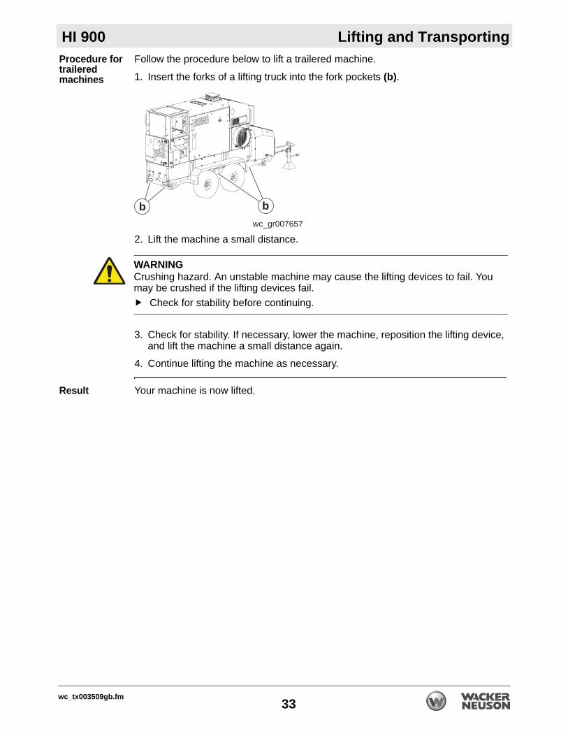
Procedure for trailered machinesFollow the procedure below to lift a trailered machine.
1. Insert the forks of a lifting truck into the fork pockets (b).
2. Lift the machine a small distance.
3. Check for stability. If necessary, lower the machine, reposition the lifting device, and lift the machine a small distance again.
4. Continue lifting the machine as necessary.
Result Your machine is now lifted.
wc_gr007657
bb
WARNINGCrushing hazard. An unstable machine may cause the lifting devices to fail. You may be crushed if the lifting devices fail.
Check for stability before continuing.
wc_tx003509gb.fm33

Lifting and Transporting HI 900
3.2 Preparing the Machine for Transport on a Truck or TrailerRequirements Machine stoppedFlatbed truck or trailer capable of supporting the machine’s weightChains, hooks, or straps capable of supporting the machine’s weight
Checklist Before transporting the machine, check the following items:
MachineCheck that all accessories are securely stored within the machine.Check that all doors and access panels of the machine are closed.Check that all electrical supplies are disconnected from the machine.For machines with external fuel supplies, check that all fuel supplies are disconnected from the machine.For machines with generators, check that the generator is shut down.
Loading and transporting equipmentCheck that the transport vehicle or trailer can support the weight of the machine.Check that the transport vehicle or trailer is wide enough to support the machine.Check that the wheels of the transport vehicle or trailer are chocked during the loading process.Check that the transport vehicle or trailer is clean and free of grease, oil, ice, and other loose material.If the machine is mounted to a trailer, check that the jackstand or other transport block (piece of wood or other similar material) is available to support the trailer tongue during transporting. Do not use the machine’s trailer jack to support the trailer tongue during transporting.Check that any ramps used in the loading process:
Can support the weight of the machine.Are clean and free of grease, oil, ice, and other loose material.Are securely connected to the transport vehicle or trailer.Are of sufficient length to keep the loading angle 15° or less.
In addition:Check that the loading area is flat and the ground is stable.Check the overall height of the machine once it is loaded on the truck or trailer.Plan your travel route so there will be adequate clearance for overpasses, road signs, buildings, etc.Check local regulations regarding transporting and obey these regulations.
WARNINGCrushing hazard. Improperly securing the machine can lead to a crushing hazard.
Use only the designated tie-down points to secure the machine to a truck or trailer.
wc_tx003509gb.fm34

HI 900 Lifting and Transporting
3.3 Before Towing ChecklistBefore towing the machine, check the licensing requirements for trailers in your area. Also check the following items:
Hitch and couplerCheck that the towing vehicle and hitch have a rating equal to or greater than the GVWR of the machine. See Technical Data.Check that the hitch of the towing vehicle and coupler of the trailer are compatible.Check the condition of both the coupler and the hitch. Check that all fasteners on the coupler are secure.Check that the coupler has fresh grease applied to it.
WheelsCheck that all lug nuts are in place and are properly torqued.Check the tread wear of the tires. Check that the tires are inflated to the proper pressure.
Trailer operationCheck that the directional and running lights on the trailer function correctly.Check that the safety chains of the trailer are connected to the towing vehicle using a crisscross pattern.Check that the trailer’s breakaway cable is attached to the towing vehicle.Check the operation of the trailer brakes by braking the towing vehicle at a slow speed. Both the vehicle and the trailer must brake smoothly. If the trailer pushes, check the fluid level in the surge brakes or the operation of the electric brakes.Test the function of the breakaway system.
wc_tx003509gb.fm35

Lifting and Transporting HI 900
3.4 Testing the Breakaway System (Electric Brakes)Requirements VoltmeterBattery charger or backup battery (charged)
When Test the breakaway system:Before towingMonthly if the machine is not in service
Procedure Perform the following procedure to test the breakaway system.
NOTICE: Disconnect the trailer wiring plug from the tow vehicle before testing. Failure to do so will result in severe damage to the electronic brake control.
1. Connect the machine/trailer to the tow vehicle.
2. Disconnect the trailer wiring plug (a) from the tow vehicle.
3. Pull the breakaway pin (b) out of the brake switch (c) (to activate the brakes) and attempt to tow the machine/trailer at a very slow speed (less than 5 mph). When activated, a properly working breakaway system will cause substantial drag on the trailer wheels and may even cause the trailer wheels to lock.
4. Stop the tow vehicle.
This procedure continues on the next page.
wc_gr008513
a
wc_gr008514
b
c
WARNINGPersonal injury hazard. A faulty breakaway system may lead to an accident and personal injury if the machine/trailer breaks away.
Do not tow the machine/trailer if the breakaway system is faulty.
wc_tx003509gb.fm36

HI 900 Lifting and Transporting
Continued from the previous page.5. If the brakes did not function, check the voltage of the breakaway battery. To do so:a. Remove the cover of the battery box.b. Remove the wires connected to the breakaway battery (d).c. Measure the voltage. If 12–14 VDC is not measured, replace or recharge the
breakaway battery.
6. If 12–14 VDC was measured but the brakes did not function, there is a wiring or mechanical fault with the brakes. Repair any faults before towing.
7. If the brakes function properly:a. Reconnect the wires to the breakaway battery.b. Re-install the cover to the battery box.c. Re-install the breakaway pin (b) into the brake switch.d. Connect the trailer wiring plug to the tow vehicle.
Result The procedure to test the breakaway system is now complete.
wc_gr008515
d
VDC
1000200
202200m
F V
A
V- COM
wc_tx003509gb.fm37

Lifting and Transporting HI 900
3.5 Testing the Breakaway System (Hydraulic Surge Brakes)Requirements Hydraulic reservoir filledMachine parked on a flat surface
When Test the breakaway system:Before towingAfter filling the hydraulic reservoir
Procedure Perform the following procedure to test the breakaway system.
1. Position the machine/trailer on a flat surface.
2. Connect the breakaway cable (a) to the tow vehicle. Do not connect the machine/trailer to the tow vehicle via the hitch.
3. Slowly move the tow vehicle so that it pulls on the breakaway cord until the emergency lever reaches its second notch (b) and locks into the ON position.
4. Connect the machine/trailer to the tow vehicle via the hitch.
5. Attempt to tow the machine/trailer at a very slow speed (less than 5 mph). When activated, a properly working breakaway system will cause substantial drag on the trailer wheels and may even cause the trailer wheels to lock.
6. If the brakes did not function, repair any faults before towing.
This procedure continues on the next page.
wc_gr008509
a
wc_gr008508
b
WARNINGPersonal injury hazard. A faulty breakaway system may lead to an accident and personal injury if the machine/trailer breaks away.
Do not tow the machine/trailer if the breakaway system is faulty.
wc_tx003509gb.fm38

HI 900 Lifting and Transporting
Continued from the previous page.7. Stop the tow vehicle.
8. Release the brake by simultaneously pulling on the breakaway cord and prying the locking spring with a screwdriver (c) or pry bar.
Result The procedure to test the breakaway system is now complete.
wc_gr008510
c
wc_tx003509gb.fm39

Operation HI 900
4 Operation4.1 Preparing the Machine for First Use1. Make sure all loose packaging materials have been removed from the machine.
2. Check the machine and its components for damage. If there is visible damage, do not operate the machine! Contact your Wacker Neuson dealer immediately for assistance.
3. Take inventory of all items included with the machine and verify that all loose components and fasteners are accounted for.
4. Attach component parts not already attached.
5. Add fluids as needed and applicable, including fuel, engine oil, and battery acid.
6. Move the machine to its operating location.
4.2 Recommended Fuel - DSLLow temperatures cause diesel fuel to gel. Gelled fuel will cause burner ignition failure and/or burner fuel pump damage. Always use the proper fuel for the conditions. Follow the guidelines in the table below.
NOTICE: Do not use B20 or any other type of biodiesel fuel in this machine.
Fuel Blend GuideLowest expected ambient
temperature °F (°C)When power is supplied
by the generatorWhen power is supplied by the local power utility
Below 5 (-15)
#2 diesel plus additives
100% #1 diesel plus additives
OR100% K1 kerosene,
plus additives
5 to 25 (-15 to -4)
70-30 blend of #2 diesel and #1 diesel, plus additives
OR 70-30 blend of #2 diesel
and K1 kerosene,plus additives
Above 25 (-4) Winter-blend diesel
CAUTIONFire hazard.
Do not use gasoline, crankcase oil, or any oil containing gasoline.
wc_tx003510gb.fm40
HI 900 Operation
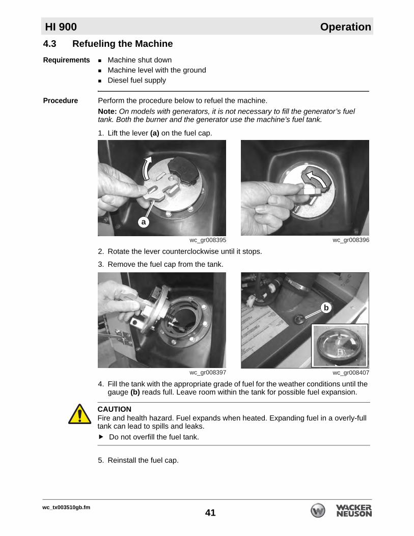
4.3 Refueling the MachineRequirements Machine shut downMachine level with the groundDiesel fuel supply
Procedure Perform the procedure below to refuel the machine.Note: On models with generators, it is not necessary to fill the generator’s fuel tank. Both the burner and the generator use the machine’s fuel tank.
1. Lift the lever (a) on the fuel cap.
2. Rotate the lever counterclockwise until it stops.
3. Remove the fuel cap from the tank.
4. Fill the tank with the appropriate grade of fuel for the weather conditions until the gauge (b) reads full. Leave room within the tank for possible fuel expansion.
5. Reinstall the fuel cap.
wc_gr008395
a
wc_gr008396
wc_gr008397 wc_gr008407
b
CAUTIONFire and health hazard. Fuel expands when heated. Expanding fuel in a overly-full tank can lead to spills and leaks.
Do not overfill the fuel tank.
wc_tx003510gb.fm41

Operation HI 900
4.4 Features and Controlsv
Ref. Description Ref. Descriptiona Exhaust rain cap l Stepb Recirculation plate m Trailer (diesel units only)c Variable Frequency Drive (VFD)
(optional)n Natural gas/liquid propane burner with gas train
(optional)d Generator (optional) o Diesel burnere Air intake duct p Blower assemblyf Trailer jackstand — —g Tie-down loop s Control panelh Lift eye (skidded units only) t Emergency stop switchj Air output duct u Lockable fuel tank cap (diesel units only)k Burner access door v Fuel tank (diesel units only)
wc_tx003510gb.fm42
HI 900 Operation
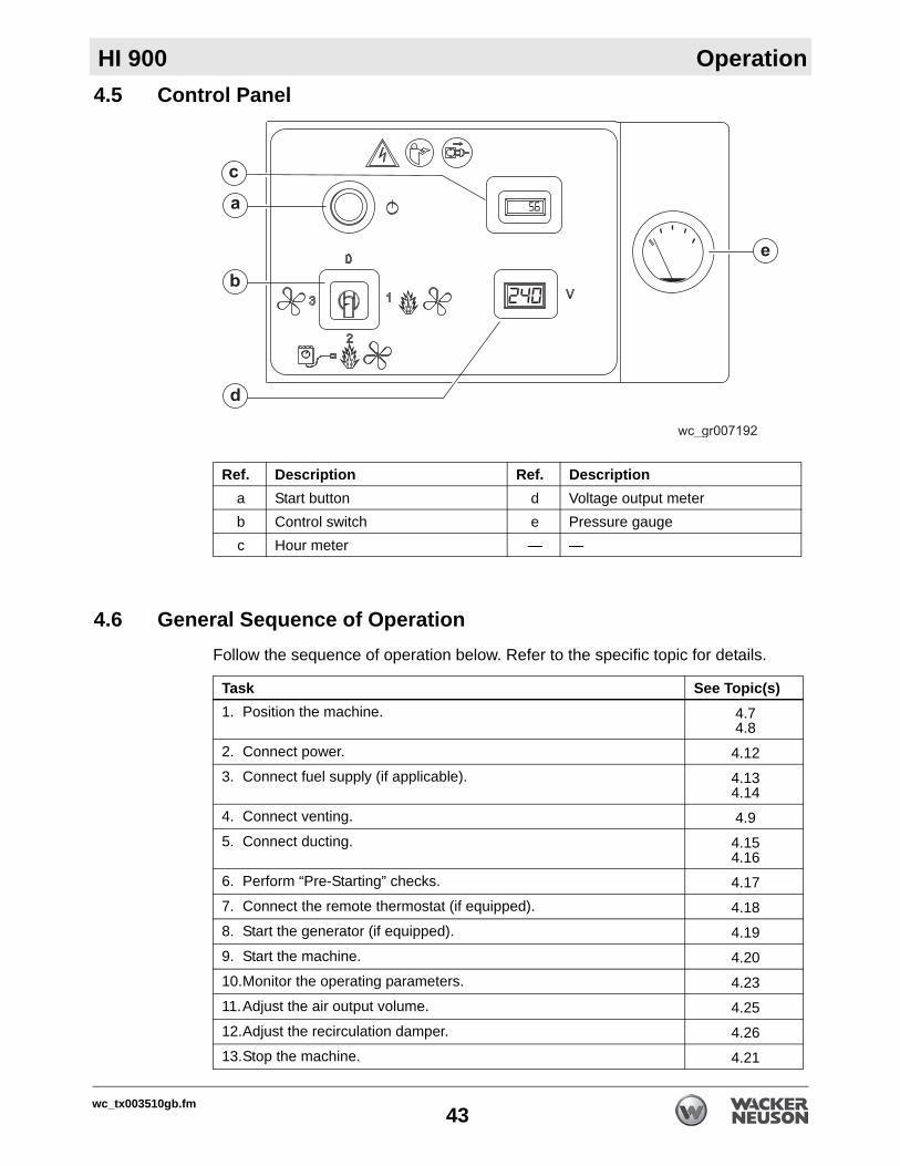
4.5 Control Panel4.6 General Sequence of OperationFollow the sequence of operation below. Refer to the specific topic for details.
Ref. Description Ref. Descriptiona Start button d Voltage output meterb Control switch e Pressure gaugec Hour meter — —
Task See Topic(s)1. Position the machine. 4.7
4.82. Connect power. 4.123. Connect fuel supply (if applicable). 4.13
4.144. Connect venting. 4.95. Connect ducting. 4.15
4.166. Perform “Pre-Starting” checks. 4.177. Connect the remote thermostat (if equipped). 4.188. Start the generator (if equipped). 4.199. Start the machine. 4.2010.Monitor the operating parameters. 4.2311.Adjust the air output volume. 4.2512.Adjust the recirculation damper. 4.2613.Stop the machine. 4.21
wc_tx003510gb.fm43

Operation HI 900
4.7 Positioning the Machine for Indoor UseNOTICE: If your machine includes a generator and/or trailer, DO NOT USE INDOORS. Refer to Positioning the Machine for Outdoor Use.
The installer must be familiar with all applicable laws, codes, regulations, or other restrictions regarding installation of Indirect-Fired (IDF) heaters.
Venting In order to use this machine indoors, the exhaust gases must be adequately vented. Refer to Suggested Venting for guidelines and diagrams.
CO Alarms Because this machine produces carbon monoxide (CO), Wacker Neuson recommends that CO alarms be installed in all structures in close proximity to the machine. CO alarms provide an extra measure of protection against this poison that you cannot see or smell.
Install battery-operated CO alarms or plug-in CO alarms with battery backup, according to the manufacturer’s instructions. CO alarms should be certified to the requirements of the latest safety standards (UL 2034, IAS 6-96, or CSA 6.19.01). Test the CO alarm batteries monthly.This procedure continues on the next page.
DANGERAsphyxiation hazard.Exhaust gas from the burner contains carbon monoxide, a deadly poison you cannot see or smell. Exposure to carbon monoxide can kill you in minutes.
Position the machine so that burner exhaust will not enter any nearby structures.
WARNINGFire hazard. Do not move the machine while it is running.
Shut down the machine before moving or repositioning it.
WARNINGFire hazard. Machines positioned on a hill or an incline may slide, break away, or roll over.
Do not position the machine on a hill or an incline.
WARNINGExplosion and fire hazard. Risk of severe injury or death.
Do not operate the machine near flammable vapors, fuels, or combustibles.
wc_tx003510gb.fm44

HI 900 Operation
Continued from the previous page.Requirements Position the machine:So that burner exhaust will not enter nearby structures.So that the machine does not block traffic.So that the machine is not near any combustible material or flammable vapor.So that all of the machine’s access doors/panels may be accessed.So that power cords do not pose tripping hazards, and so that the power cords cannot be damaged by machines or other equipment on the job site.So that the machine is on solid, stable, and level ground.So that the machine is not in direct contact with rain, spraying and/or dripping water.
NOTICE: The heater must be located at least: (i) 6 ft. (1.83 m) in the U.S.; or (ii) 10 ft . (3 m) in Canada, from any Propane-gas container.
Proximity restrictions
The machine must be located a safe distance from any other structures, vehicles, materials or other combustible surfaces. The following priximity restrictions apply for all machine installations.
6 ft. (2 m) to front10 ft. (3.1 m) to rear4 ft. (1.1 m) to sides4 ft. (1.1 m) to top20 ft (6.2 m) from outlet(s) to external fuel container
20 ft. (6.2 m)
wc_gr011431
wc_tx003510gb.fm45

Operation HI 900
4.8 Positioning the Machine for Outdoor UseThe installer must be familiar with all applicable laws, codes, regulations, or other restrictions regarding installation of Indirect-Fired (IDF) heaters.
CO Alarms Because this machine produces carbon monoxide (CO), Wacker Neuson recommends that CO alarms be installed in all structures in close proximity to the machine. CO alarms provide an extra measure of protection against this poison that you cannot see or smell.
Install battery-operated CO alarms or plug-in CO alarms with battery backup, according to the manufacturer’s instructions. CO alarms should be certified to the requirements of the latest safety standards (UL 2034, IAS 6-96, or CSA 6.19.01). Test the CO alarm batteries monthly.
Requirements Position the machine:So that burner exhaust will not enter nearby structures.So that the machine does not block traffic.So that the machine is not near any combustible material or flammable vapor.So that all of the machine’s access doors/panels may be accessed.So that power cords do not pose tripping hazards, and so that the power cords cannot be damaged by machines or other equipment on the job site.So that the machine is on solid, stable, and level ground.So that the machine is not in direct contact with rain, spraying and/or dripping water.
This procedure continues on the next page.
DANGERAsphyxiation hazard.Exhaust gas from the burner contains carbon monoxide, a deadly poison you cannot see or smell. Exposure to carbon monoxide can kill you in minutes.
Position the machine so the burner exhaust will not enter any nearby structures.
WARNINGFire hazard. Do not move the machine while it is running.
Shut down the machine before moving or repositioning it.
WARNINGFire hazard. Machines positioned on an incline may slide, break away, or roll over.
Do not position the machine on a hill or an incline.
WARNINGExplosion and fire hazard. Risk of severe injury or death.
Do not operate the machine near flammable vapors, fuels, or combustibles.
wc_tx003510gb.fm46

HI 900 Operation
Continued from the previous page.NOTICE: The heater must be located at least: (i) 6 ft. (1.83 m) in the U.S.; or (ii) 10 ft . (3 m) in Canada, from any Propane-gas container.
Proximity restrictions
The machine must be located a safe distance from any other structures, vehicles, materials or other combustible surfaces. The following proximity restrictions apply for all machine installations.
6 ft. (2 m) to front10 ft. (3.1 m) to rear4 ft. (1.1 m) to sides4 ft. (1.1 m) to top20 ft (6.2 m) from outlet(s) to external fuel container
Procedure Perform the following procedure to position the machine.
1. Place the machine near the application area on solid, stable, and level ground.
2. For machines with trailers, install chocks (a) under the wheels.
20 ft. (6.2 m)
wc_gr011428
wc_gr008340
a
wc_tx003510gb.fm47

Operation HI 900
4.9 Suggested VentingThe Installation of Venting to Natural Gas and Propane equipped models shall conform with local codes or, in the absence of local codes, with the National Fuel Gas Code ANSI Z223.1/NFPA 54 and the Natural Gas and Propane Installation Code, CSA B149.
When installing vents:Do not use B-vent exhaust pipes. Contact Wacker Neuson for alternatives.Use materials rated for 850°F (454°C).Adhere to all local and national codes.Adhere to all fire prevention regulations.Consult all appropriate governing bodies or local contractor for venting and fresh air requirements. Make sure that the room or building to be heated has sufficient ventilation to ensure that the machine has enough air to function properly.Position the machine in a manner that avoids excessive vent bends (elbows), and long horizontal runs.Keep air inlets and outlets free from obstruction. Ensure that there are no bulky objects or sheets/covers near or on the machine.Route the venting pipes in a manner that avoids flammable materials. Route the venting pipes in a manner that avoids contact with people.When the machine is connected to a flue pipe, the flue pipe shall terminate in a vertical section at least two feet long. Sufficient draft shall be created to assure safe and proper operation of the machine (minimum -0.02 in. w.c.).
DANGERAsphyxiation hazard.Exhaust gas from the burner contains carbon monoxide, a deadly poison. Exposure to carbon monoxide can kill you in minutes.
Never run the machine indoors or in an enclosed area unless the machine is vented properly according to local and national codes.
wc_gr011427
wc_tx003510gb.fm48

HI 900 Operation
4.10 Electrical and Grounding RequirementsElectrical requirements
Ensure that the machine is connected to a reliable, consistent source of electric power.The electric power source must be grounded per the requirements below and connected to a freely accessible circuit breaker.
Extension cords
Ensure that extension cords (if used) are properly sized for the installation. Do not use worn, bare, or frayed cords!Use only 3-wire type extension cords with heavy-duty plugs.The maximum length of extension cord usage per circuit is 30 m (100 ft). For 240V connections, use 8-gauge extension cords.For 120V connections, use 12-gauge extension cords.
Grounding requirements
Electrical grounding must comply with the National Electric Code ANSI/NFPA 70 or the CSA C22.1 Canadian Electrical Code, Part 1.
4.11 Power Requirements for Third-Party GeneratorsNOTICE: Machine damage may occur if an undersized generator (genset) is used to power the machine. The starting kVA of the generator must be at least 33 kVA at a maximum voltage dip of 20%.
WARNINGFire hazard and electric shock hazards. The use of an inappropriate power supply, or undersized extension cords, can lead to fire and electric shock. Fire and electric shock can cause severe injury.
Before use, ensure that the machine is properly connected to an appropriate power source and grounded per the requirements provided below.Do not use undersized extension cords.
wc_tx003510gb.fm49
Operation HI 900
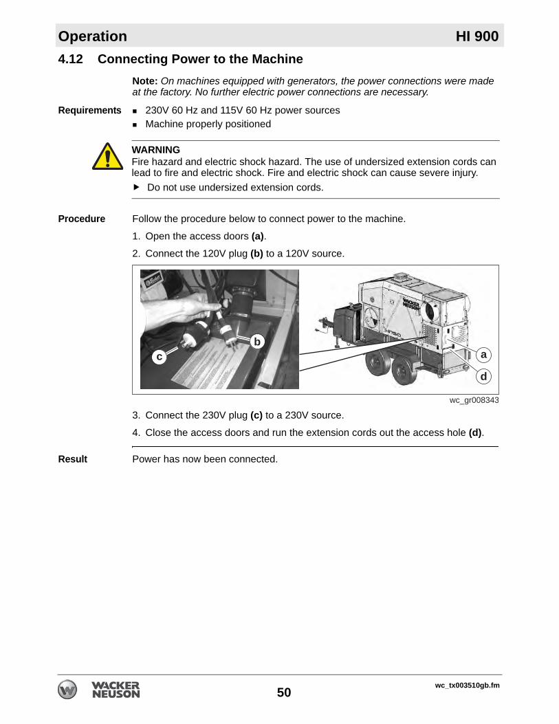
4.12 Connecting Power to the MachineNote: On machines equipped with generators, the power connections were made at the factory. No further electric power connections are necessary.
Requirements 230V 60 Hz and 115V 60 Hz power sourcesMachine properly positioned
Procedure Follow the procedure below to connect power to the machine.
1. Open the access doors (a).2. Connect the 120V plug (b) to a 120V source.
3. Connect the 230V plug (c) to a 230V source.
4. Close the access doors and run the extension cords out the access hole (d).
Result Power has now been connected.
WARNINGFire hazard and electric shock hazard. The use of undersized extension cords can lead to fire and electric shock. Fire and electric shock can cause severe injury.
Do not use undersized extension cords.
cb
wc_gr008343
d
a
wc_tx003510gb.fm50

HI 900 Operation
4.13 Connecting the Gas LineOverview The HI 900G model heaters include a 1-inch NPT inlet on the gas safety valve /pressure regulator body. The gas supply line connects to the inlet.
Gas pressures
The table below lists the minimum and maximum gas supply pressures with the burner operating.
Regulating LP gas pressure
The installation of a secondary pressure regulator is strongly recommended when using LP gas. A secondary pressure regulator ensures a steady flow of LP to the burner. A regulator is especially valuable when the gas supply pressure is inconsistent.Note: Gas piping, pressure regulators, and fittings are not included with this heater and must be provided by the customer.
WARNINGExtreme fire and explosion hazard!
Only a licensed, professional gas technician shall perform installation, fuel sup-ply connection, setup, adjustment, and testing of gas lines. All connections and settings must conform to relevant local, state, provincial, and federal requirements.
WARNINGFire, explosion, inhalation, and asphyxiation hazard. The installation of an external fuel cylinder (natural gas or liquid propane) presents several hazards.
The installation of an external fuel cylinder (natural gas or liquid propane) must conform to local codes or, in the abscence of codes, with the National Fuel Gas Code ANSI Z223.1/NFPA 54 and the Natural Gas and Propane Installation Code, CSA B149.1.
Fuel Minimum supply pressure
Maximum supply pressure
Natural gas 8 in. w.c. 14 in. w.c.Liquid propane (LP) 8 in. w.c. 14 in. w.c.
wc_tx003510gb.fm51

Operation HI 900
4.14 Connecting to a Fuel CylinderIf cylinders are used to supply fuel to the heater (Liquid Propane or Natural Gas), the cylinder must be at least 100 lb. capacity. These cylinders must supply a vapor withdrawal only.
1. All cylinder connections must be made using a wrench to tighten the fitting.
2. Be sure that the cylinder valve is in the closed position when connecting or disconnecting the cylinder.
3. Proper procedure for gas leak testing: a soap and water solution must be applied to all connections in order to leak check the system.
4. The hose assembly must be visually inspected prior to each use of the heater.
5. The gas must be turned off at the propane supply cylinder(s) when the heater is not in use.
6. When the heater is to be stored indoors, the heater must be disconnected and the cylinders removed from the heater and stored in accordance with the standards mentioned above.
WARNINGFire, explosion, inhalation, and asphyxiation hazard. The installation and removal of an external liquid propane fuel cylinder presents several hazards.
Install and remove external fuel cylinders (liquid propane) in conformity with local codes or, in the absence of codes, with the Standard for the Storage and Handling of Liquefied Petroleum Gases, ANSI/NFPA 58, and the Natural Gas and Propane Installation Code, CSA B149.1.
WARNINGFire and explosion hazard! To reduce the risk of fire and explosion:
Determine size of supply piping using appropriate piping tables that consider the length of pipe run from the source as well as the BTU/h rating of the appli-ance.Have a licensed, professional technician perform installation, fuel supply con-nection, setup, adjustment, and testing of fuel lines. Ensure that all connections and settings conform to relevant local, state, provincial, and federal requirements.
wc_tx003510gb.fm52

HI 900 Operation
4.15 Flex Ducting OptionsRefer to the chart below for the maximum allowable return and supply duct lengths for your machine.
NOTICE: Do not exceed the maximum total lengths specified in the chart. Exceeding these lengths, or blocking any of the duct openings, constricts the air flow through the machine and may cause a high-temperature shut-down fault.
MODEL RETURN DUCTING SUPPLY DUCTING
— Return duct
adapter
Maximum number of 25 ft. duct sections
Totalcombined
length
Supply duct
adapter
Length of each duct
section (ft)
Maximum duct sections per opening
Total combined
lengthQty Length
AB XHDHI 770XHD
1 X 20 in. 8 200 ft 1 X 20 in. 25 8 200 ft 200 ft
1 X 16 in. 25 6 150 ft 150 ft
2 X 12 in. 25 3 75 ft 150 ft
HI110 Return ductwork not available. 12 in. 25 1 25 ft 25 ft
HI200 14 in. 25 1 25 ft 25 ft
HI300 16 in. 25 1 25 ft 25 ft
HI300 HD 2 X 12 in. 25 1 25 ft 50 ft
HI 750HI 900
2 X 20 in. 4 100 ft 2 X 20 in. 25 8 150 ft 300 ft
3 X 20 in. 25 9 225 ft 675 ft
3 X 16 in. 25 3 75 ft 225 ft
4 X 12 in. 25 1 25 ft 100 ft
wc_tx003510gb.fm53

Operation HI 900
4.16 Installing the Heater DuctOverview Optional ducts can be connected to the air outlet. This allows warm air to be evenlydistributed throughout the heating area.
NOTICE: When using ducts, observe the static air pressure limits specified in Technical Data.
Requirements Machine shut down and cooledMachine properly positioned
Procedure To install the ducts, carry out the following procedure.
1. Open the clamps (a). 2. Slide the duct (b) onto the duct adapter (c).3. Close the clamp to secure the duct in place.
Result The procedure to install the heater duct is now complete.
CAUTIONHot surface hazard. The machine surfaces may be hot.
Allow the machine to cool for a minimum of ten minutes before touching it.
wc_tx003510gb.fm54

HI 900 Operation
4.17 Pre-Starting ChecksRequirements Machine properly positionedPower connected to the machine
Checks Before starting the machine, check the following items:
Result The machine is now ready to be started.
Item TaskFuel Check that the fuel tank is full (if applicable). See
topic Recommended Fuels.
Check that the gas supply (if applicable) is connected and has the proper pressure. See topic Checking the Supply Gas Pressure.
Fuel tank cap Check that the fuel tank cap (if applicable) is secure.
Electric power Check that proper power supplies have been connected. See topic Connecting Power to the Machine.
Ducts and duct adapters Check that all ducts and duct adapters have been properly installed.
Generator Check that the generator (if applicable) is properly maintained. See the OEM documentation for more information.
wc_tx003510gb.fm55
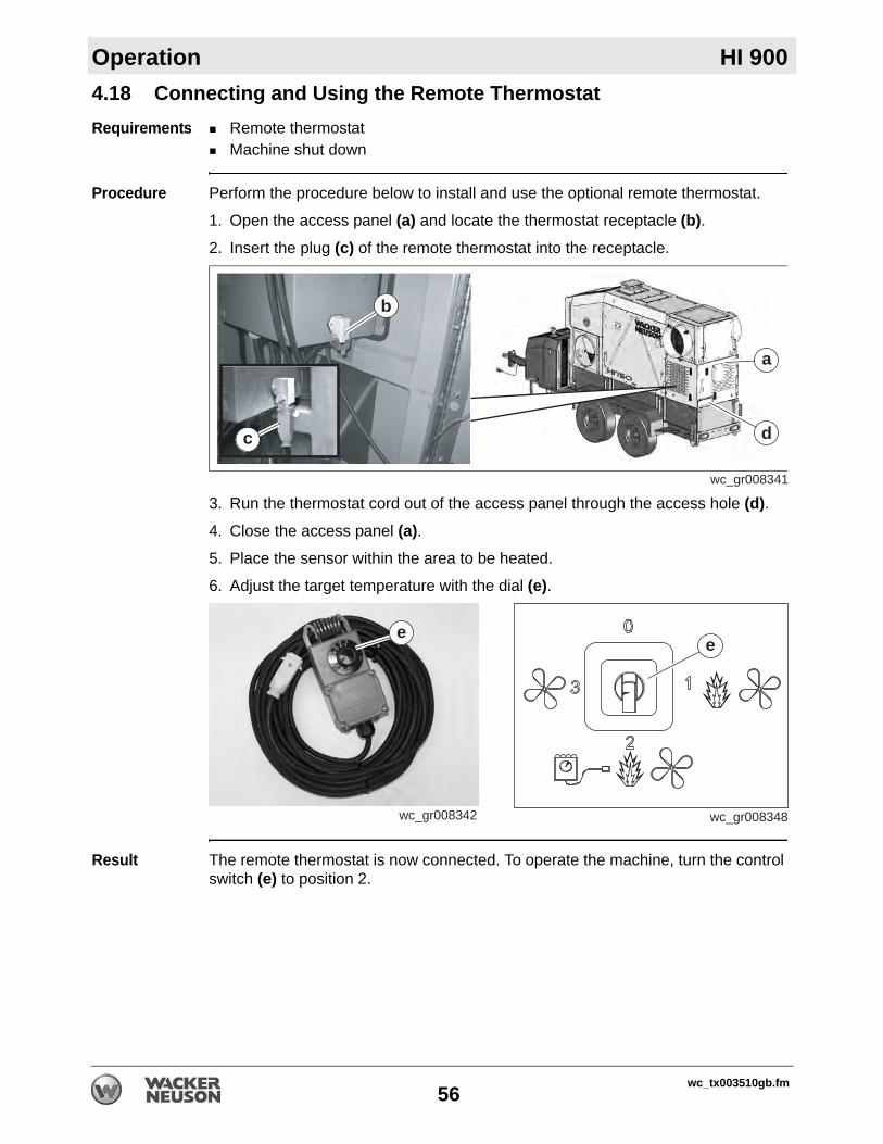
Operation HI 900
4.18 Connecting and Using the Remote ThermostatRequirements Remote thermostatMachine shut down
Procedure Perform the procedure below to install and use the optional remote thermostat.
1. Open the access panel (a) and locate the thermostat receptacle (b).2. Insert the plug (c) of the remote thermostat into the receptacle.
3. Run the thermostat cord out of the access panel through the access hole (d).4. Close the access panel (a).5. Place the sensor within the area to be heated.
6. Adjust the target temperature with the dial (e).
Result The remote thermostat is now connected. To operate the machine, turn the control switch (e) to position 2.
wc_gr008341
a
d
b
c
wc_gr008342
e
wc_gr008348
e
wc_tx003510gb.fm56
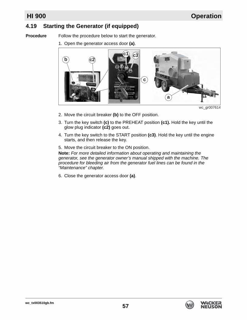
HI 900 Operation
4.19 Starting the Generator (if equipped)Procedure Follow the procedure below to start the generator.1. Open the generator access door (a).
2. Move the circuit breaker (b) to the OFF position.
3. Turn the key switch (c) to the PREHEAT position (c1). Hold the key until the glow plug indicator (c2) goes out.
4. Turn the key switch to the START position (c3). Hold the key until the engine starts, and then release the key.
5. Move the circuit breaker to the ON position. Note: For more detailed information about operating and maintaining the generator, see the generator owner’s manual shipped with the machine. The procedure for bleeding air from the generator fuel lines can be found in the “Maintenance” chapter.
6. Close the generator access door (a).
wc_gr007614
a
b c2c3c1
c
wc_tx003510gb.fm57

Operation HI 900
4.20 Starting the MachineRequirements Power connectedGenerator started (if equipped)Pre-starting checks complete
Procedure Follow the procedure below to start the machine.
1. Check that the emergency stop switch (a) is in the disengaged position.
2. Open the panel door. Press the green start button (b).3. Rotate the control switch (c) to the “1” position, or if a remote thermostat is
being used, rotate the control switch to the “2” position. Close the panel door.
Operational sequence
The following sequence of events will occur.
1. If your machine is equipped with a VFD, a preheating cycle begins. Allow 30 minutes for preheating to occur.
2. The burner will complete a startup sequence, and then will start firing.In applications in which a remote thermostat is not being used, the burner will fire continuously.In applications in which a remote thermostat is being used, the burner will fire until the air temperature of the application area reaches the target temperature set by the remote thermostat. At that time, the burner will shut off, but the blower will continue to operate. When the air temperature of the application area falls below the target temperature set by the remote thermostat, the burner will refire. The process continues as long as there is fuel for the burner.
3. The blower will start. v
wc_gr008344
a
b
c
wc_gr007193
c
wc_tx003510gb.fm58

HI 900 Operation
4.21 StoppingProcedure Follow the procedure below to stop the machine.1. Turn the control switch (c) to the OFF (0) position.
Stopping sequence
The following sequence of events will occur.
1. The burner will shut down. 2. The blower will stop when the machine is sufficiently cool.
Restarting Perform the following to restart the machine.
1. Turn the control switch (c) to the either position 1, position 2, or position 3. Note: The green start button does not need to be pressed to restart the machine if electric power is still connected to it.
2. Use the machine as normal.
Complete shutdown
Perform the following to shut down the machine.
For machines without gensets (i.e., shore-powered machines):
1. Stop the machine as stated above.
2. Disconnect the power supplies when the blower stops.
3. Disconnect and pack up the air ducts.
For machines with gensets:
1. Move the genset circuit breaker to the OFF position when the blower stops.
2. Allow the genset engine to run for approximately 5 minutes with no load.
3. Turn the genset key switch to the OFF position.
4. Disconnect and pack up the air ducts.
WARNINGElectric shock hazard. Electric power is still active at the blower and at the control switch even when the machine is turned OFF.
Disconnect all electric power from the machine before servicing it.
wc_gr007193
c
wc_tx003510gb.fm59

Operation HI 900
4.22 Emergency Shutdown ProcedureBackground This machine is equipped with an emergency stop push button. When pressed, thispush button shuts down the machine and disconnects all power to the machine controls and the generator if equipped.
NOTICE: Do not use the emergency stop push button for normal shutdown.
Stopping the machine
To stop the machine and disconnect power to the controls:
1. Press the emergency stop push button.
Reconnecting the power
To reconnect the power to the controls:
1. Twist the emergency stop push button. It will disengage.
2. Restart the generator if equipped.3. Press the reset button.
wc_tx003510gb.fm60

HI 900 Operation
4.23 Monitoring the Operating ParametersBackground Monitor the machine while it is operating to ensure safe and efficient operation.Parameters Monitor the following parameters while the machine is operating.
Parameter Notes
Fuel level (“D” models only)
Add fuel as needed.
Voltage output (a)
Voltage output should be 240V If voltage is less than 240V or fluctuating, check to make sure the power supply is consistent. An extension cord that is undersized or too long will also cause a drop in voltage out-put. Make sure that an appropriate exten-sion cord is being used for your particular application. Contact Wacker Neuson Prod-uct Support for assistance if needed.
Air pressure (b)
Operating pressure: 0 to 1.4 in. w.c.If operating pressure is higher than 1.4 in. w.c., check for obstructed or blocked ducts.
wc_gr008349
b
a
wc_tx003510gb.fm61

Operation HI 900
4.24 Operating at High ElevationsBackground If using the machine at or above elevations of 1524 m (5000 ft) asl (above sealevel), periodic monitoring and additional maintenance are necessary to preserve the machine’s systems. The following procedures will ensure that the machine runs smoothly and that premature soot build-up will be reduced.
Guidelines Use the guidelines below to ensure efficient operation of the machine. Refer to the specific topic for details.
High Elevation Nozzle
Wacker Neuson recommends using a 3.50-60° B @ 140 psi nozzle when operating at high elevations. Contact Wacker Neuson Product Support to order a replacement nozzle.
Task When See Topic1. Conduct a smoke spot test. After making any adjustments
and/orEvery 1000 hours
7.2
2. Adjust the air output volume. Before operation 4.23
3. Adjust the fuel pressure. Before operation 7.7 & 8.7
4. Replace the burner nozzle. Before operation 7.4
WARNINGFire hazard. The use of incorrect nozzles could cause fire or impaired combustion. Impaired combustion may cause under-firing, over-firing, sooting, sudden expulsion of hot gases, and smoke.
Use only the factory-installed or recommended nozzles.
wc_tx003510gb.fm62

HI 900 Operation
4.25 Adjusting the Air Output VolumeBackground The volume of heated air produced by your machine can be increased ordecreased depending on job site requirements.
Procedure Follow the procedure below to adjust the air output volume.
1. Loosen the locking handle (a) on the adjusting lever (b).
2. Move the adjusting lever backward to increase output volume, or forward to decrease output volume.
3. Tighten the locking handle when the adjusting lever is in the desired position.
wc_gr007652
++––
a
b
wc_tx003510gb.fm63

Operation HI 900
:4.26 Using the Recirculation DamperNOTICE: Do not operate the machine with the inlet ports covered. Operating the machine with the inlet ports covered will cause the machine to shut down due to overheating.
Opening the recirculation damper (a) introduces fresh air into the main air sup-ply. Running the machine in this mode pressurizes the heated space.Closing the recirculation damper recirculates the heated air, which allows the machine to run more economically.
wc_gr008347
a
wc_tx003510gb.fm64

HI 900 Operation
4.27 Operating States of the Beckett Burner ControllerBurner states The burner control has several states that it sequences through during normal operation. These operating states are described below..
Standby
Run
Ignition
carryover
State
10 30
Operating
wc_gr007662
State Action or FunctionStandby As soon as power is supplied to the burner control, the burner control
enters the standby state in which it will remain until there is a call for heat or power is disconnected.
Valve-on delay
(pre-time)
When the setpoint of the temperature controller is set to a temperature higher than that of the heat transfer fluid, the output contacts of the temperature controller close, completing a circuit between the two terminals labeled “T” of the burner control. This is the call for heat. The burner control enters the valve-on-delay state.
The valve-on-delay state lasts 15 seconds. During this state:Power is sent to the burner motor.Power is sent to the electrodes.If the cad cell detects flame anytime during the valve-on-delay state, the burner control goes into the lockout state.
Trial-for-ignition
The trial-for-ignition state immediately follows the valve-on-delay state. During this state:
The fuel shut-off valve is opened (energized).Pressurized fuel atomizes at the burner nozzle.The atomized fuel is ignited by the electrodes.The burner fires and the flame is monitored by the cad cell.If flame is detected, the burner control moves to the ignition carryover state.
If flame is not detected within 15 seconds: The burner control enters the lockout state.Power is disconnected from the fuel shut-off valve, electrodes, and the burner motor.
wc_tx003510gb.fm65

Operation HI 900
Ignition carryover
The ignition carryover state starts as soon as the flame is established.During this state:
The fuel shut-off valve is open (energized).Pressurized fuel atomizes at the burner nozzle.The atomized fuel is ignited by the electrodes. The electrodes stay powered for up to 10 seconds after flame is sensed.
When the ignition carryover state has elapsed:The ignition transformer is shut off.The burner control enters the run state.
If the flame is lost during the ignition carryover state: If the lockout time has not expired, the burner control returns to trial-for-ignition state.If the lockout time has expired, the burner control enters the recycle mode.
Run The run state starts and continues once the ignition carryover state has elapsed. During this state:
The fuel shut-off valve is open (energized).Pressurized fuel atomizes at the burner nozzle.The flame is monitored by the cad cell.
When the setpoint is reached (call for heat satisfied), the burner control enters the burner-motor-off delay state.If the flame is lost during the run state:
The burner control enters the recycle mode.
Burner-motor-off-delay
The burner-motor-off-delay state starts immediately after the setpoint is reached, i.e., the call for heat has been satisfied. The time of this state is 30 seconds. During this state:
The output contacts of the temperature controller open, interrupting the circuit between terminals labeled “T”.The fuel shut-off valve closes (de-energizes).The burner motor runs until the burner-motor-off delay expires, then the burner motor turns off.The burner control returns to the idle mode.
If the cad cell detects flame during the burner-motor-off-delay state:The burner control goes into the standby state.
State Action or Function
wc_tx003510gb.fm66

HI 900 Operation
Lockout The lockout state is described below.Recycle The recycle mode is described below.
State Action or FunctionLockout The burner will enter the lockout state for the following reasons:
Trial for ignition time has expired without flame being established.Cad cell detects flame at the end of the valve-on delay state.Recycle time budget expires.Relay check failure.
Note: The burner control cannot reset by interrupting the voltage.
During the lockout state:The burner will not fire.The red reset button / lockout light on the burner control will flash during a soft lockout condition.The reset button / lockout light will remain on continuously during a hard lockout condition.The burner fault light on the control panel will illuminate.
To clear the soft lockout fault so a restart can be attempted, press and release the reset button. Note: After the third attempt to manually clear the lockout fault, the burner control will enter the hard lockout mode. To clear the hard lockout, press and hold the reset button for 15 seconds.
wc_gr007665
Yellowpump prime
Greenflame / recycle
RedReset button / lockout
State Action or FunctionRecycle The burner will enter the recycle mode if the flame is lost while
the burner is firing.During the recycle mode:
The burner control shuts down the burner.The burner control enters a 60-second delay, then repeats the ignition sequence.The green flame / recycle light on the control panel flashes.The burner control attempts to recycle each time the flame is lost, up to three times. If flame is not established after the third time, the burner control enters the hard lockout state.
To clear the hard lockout fault so a restart can be attempted, press and hold the reset button for 15 seconds.
wc_tx003510gb.fm67

Operation HI 900
Pump prime The pump prime mode is described below.
State Action or FunctionPump prime During the pump prime mode, the cad cell is disregarded,
allowing the technician to prime the pump without having to jumper the cad cell.
This mode lasts 4 minutes. During this mode:Power is sent to the burner motor/fuel pump.Power is sent to the electrodes.The cad cell is disregarded.The yellow pump prime light illuminates.
To enter the pump prime mode:1. Prepare the burner for priming. Do not allow oil to spray
into a hot combustion chamber.Attach a hose over the bleed port fitting.Fully open the pump bleed valve.Use a suitable container to collect the purged oil.
2. Set the temperature controller so there is a call for heat.3. After the burner starts, press and hold the reset button for 15
seconds until the yellow light turns on, then release the reset button. The yellow light will turn off, the burner control pow-ers down the burner, and the burner will then start up again. At burner startup, press and release the reset button to enter the pump prime mode. The yellow light will turn on.
To exit the pump prime mode, do one of the following:Set the temperature controller so there is no longer a call for heat and press the reset button for at least 1 second. The burner control will return to the standby state.Wait four minutes for the pump prime mode to time out. The burner control will return to the standby state. The yellow light will turn off.
wc_tx003510gb.fm68

HI 900 Operation
4.28 Operating States of the Riello Burner ControllerStart-up cycle
Start-up cycle diagnosticsDuring startup, the controller indicates the phase/state of the burner according to the following table.
wc_gr008351
3s40s40smax. 2s max. 2s
Lock-out, due to ignition failureNormalThermostat
MotorIgnition transformer
ValvesFlame
Lock-out
State/Phase Color code
Pre-purging
Ignition phase
Operation, flame OK
Operating with weak flame signal
Electrical supply lower than ~ 170V
Lock-out
Extraneous light
Index: Off � Yellow Green Redwc_gr008352
wc_tx003510gb.fm69

Operation HI 900
Entering the burner controller diagnostic modeThe burner controller includes a diagnostic mode / function through which causes of malfunctions may be determined. The controller sends out a sequence of pulses which are visible on the reset button / LED display.To enter the diagnostic mode:
1. Wait at least 10 seconds after the controller has entered the lock-out mode.
2. Press the reset button for more than 3 seconds. Release the reset button when the yellow LED flashes.
The burner controller will send out a sequence of pulses, one second on and one second off. There is a 3-second interval between each sequence. The number of pulses identifies the probable cause of a problem. See the chart below.
After the determining the cause of the malfunction, correct the issue.
Resetting the burner controller
To return the burner controller to the operation mode, reset the burner controller by pressing and holding the reset button for 1–3 seconds. The burner will restart after a 2-second pause.
Press resetfor > 3s 3sPulses Pulses
RED LED onwait at least 10s
IntervalLock-out
wc_gr008353
Signal Probable Cause
2 pulses
The flame does not stabilze at the end of the safety time due to one of thefollowing:– faulty ionization probe– faulty or soiled gas valves– neutral/phase exchange– faulty ignition transformer– poor burner regulation (insufficient gas)
3 pulses
Minimum air pressure switch does not close due to one of the following:– make sure pressure switch trips to produce lockout– air pressure switch faulty– air pressure switch incorrectly regulated– fan motor does not run– maximum air pressure switch operating
4 pulses
Minimum air pressure switch does not open or light in the chamber beforefiring due to one of the following:– air pressure switch faulty– air pressure switch incorrectly regulated
7 pulsesLoss of flame during operation due to one of the following: – poor burner regulation (insufficient gas)– faulty or soiled gas valves– short circuit between ionization probe and earth
10 pulses– Wiring error or internal fault
wc_gr008354
wc_tx003510gb.fm70

HI 900 Operation
wc_tx003510gb.fm71

Factory-Installed Options HI 750
5 Factory-Installed Options5.1 Variable Frequency Drive (VFD)Overview The blower motor on your machine requires a surge of electrical current when
starting. This means that the amount of power needed to initially start the motor is larger than the power required to keep it running. The motor may not start if the power source does not provide enough current to overcome the surge.Machines equipped with generators include a Variable Frequency Drive (VFD). The VFD (a) allows the motor to start at a low RPM with a gradual increase to full operating speed. This reduces the amount of current needed to start the motor.
Changing VFD settings
The VFD is factory-set for the motor to reach full operating speed 5 seconds after startup. Contact your Wacker Neuson representative if there is a need to adjust the time interval.
5.2 TrailerOverview Mobile HI 900 IDF Heaters are mounted on trailers equipped with electric brakes or
surge brakes, depending on the model selected.Electric brakes draw power from the towing vehicle. When the brake pedal is applied, a magnetic actuator forces the brake shoes against the brake drum to slow the trailer. A battery-powered breakaway cable is included as a safety measure to stop the trailer if both the safety chains and coupler fail.Surge brakes operate independently of the towing vehicle. When the brake pedal is applied, centrifugal force actuates a master hydraulic cylinder in the trailer. Hydraulic fluid then forces the brake shoes against the brake drum to slow the trailer.
Trailer manual A trailer owner’s manual is provided with the HI 900. Read the manual and follow the manufacturer’s instructions for using, adjusting, maintaining, and storing the trailer.
Towing safety Read Towing Safety in this Operator’s Manual for additional information about how to safely tow the HI 900 IDF Heater.
wc_gr007613
a
72 wc_tx003511gb.fm

HI 750 Factory-Installed Options
5.3 GeneratorBackground Your machine may be equipped with a diesel generator (a). The generator providesa consistent source of operating power for the machine. Power cords are plugged into the generator control panel (b) at the factory.
NOTICE: Do not use the generator to power any other devices. Connecting other equipment to the generator may cause the circuit breakers to trip.
Operating the generator
For complete operating and maintenance instructions, refer to the generator owner’s manual shipped with your machine.
5.4 Diesel BurnerDescription Machines equipped with diesel burners use diesel (oil) fuel for combustion. Electric
power is also required to operate the machine. If power is supplied by the optional diesel generator, the machine becomes a self-contained heater suitable for mobile applications.
Diesel burner kit
A diesel burner conversion kit is available. Contact your Wacker Neuson dealer for more information.
5.5 Natural Gas (NG)/Liquid Propane (LP) BurnerDescription Machines equipped with gas burners are best suited for permanent installations.
The gas burner is fueled by Natural Gas (NG) or Liquid Propane (LP) depending on the user’s requirements. Electric power is also required to operate the machine and must be provided by an external source.
Gas burner kit A gas burner conversion kit is available. Contact your Wacker Neuson dealer for more information.
wc_gr007616
a b
wc_tx003511gb.fm 73

wc_tx003512gb.fm74
Accessories HI 9006 Accessories
6.1 Available AccessoriesAvailable accessories
The following Wacker Neuson accessories are available. Contact your Wacker Neuson dealer for more information.
Item Description/PurposeRemote thermostat Allows the user to remotely control the target
temperatureInlet and outlet covers Vinyl covers that protect the interior of the machine
from the elements during transport or storageDuct adapters Various sizes of detachable inlet and outlet adaptersFlexible ducts Vinyl ducts that offer a method of directing inlet and
outlet airBurner conversion kits Allows the user to switch the fuel source from DSL to
NG/LP and vice versa

HI 900 Burner Setup—Oil
7 Burner Setup—Oil7.1 Factory Settings
7.2 Setting up the BurnerBackground The burner consists of several different components and subsystems. Each of
these components or subsystems must be operating correctly for the burner to function properly.
Fuel Low ambient temperatures cause diesel fuels to gel. Gelled fuels will cause burner ignition failure and/or burner fuel pump damage. Always use the proper fuel for the conditions.
Tools required The following tools are required to adjust the burner:High-quality combustion analyzer Smoke spot testerFuel pressure test gaugeGeneral hand tools
Mandates Adjustments must be made so that the machine conforms to the requirements of local, state, provincial, and federal codes and authorities. Adjustments shall be made at the job site.
This procedure continues on the next page.
Head Firing rategph Nozzle size Fuel pressure
psiInitial head
settingAir bandsetting
Air shutter
CF 800 KJ 6.4 5.5 60° B 140 4 8 7
Fuel Blend GuideLowest expected ambient
temperature °F (°C)When power is supplied
by the generatorWhen power is supplied by the local power utility
Below 5 (-15)
#2 diesel plus additives
100% #1 diesel plus additives
OR100% K1 kerosene,
plus additives
5 to 25 (-15 to -4)
70-30 blend of #2 diesel and #1 diesel, plus additives
OR 70-30 blend of #2 diesel
and K1 kerosene,plus additives
Above 25 (-4) Winter-blend diesel
wc_tx003513gb.fm75

Burner Setup—Oil HI 900
Continued from the previous page.When Adjust the burner:Before operating the machine at elevations 305 m (1,000 ft) above or below the location of the previous adjustmentsBefore starting at a new job siteAfter any burner maintenance or repair has been performedIf burner performance is in question
Procedure Follow the procedure below to set up the burner.
1. Shut down the machine.
2. Set the burner electrodes.(See topic Setting/Checking the Electrodes.)
3. Check the burner nozzle.(See topic Replacing the Burner Nozzle.)
4. Check/set the “Z” distance.(See topic Setting the “Z” Distance.)
5. Set the air settings.(See topic Adjusting the Air Settings.)
6. Start the machine and the burner.
7. Check/set the fuel pressure.(See topic Adjusting the Fuel Pressure.)
8. Conduct a smoke spot test. Follow the smoke spot tester manufacturer’s instructions and the general guidelines below.
Use the access hole in the exhaust stack.Take several samples as the heater warms.Take the final sample just before the heater reaches 71°C (160°F).
This procedure continues on the next page.
wc_gr008047
wc_tx003513gb.fm76

HI 900 Burner Setup—Oil
Continued from the previous page.9. Analyze the combustion. Follow the combustion analyzer manufacturer’s instructions and the general guidelines below.
Use the access hole in the exhaust stack.Take several samples as the heater warms. Take the final sample just before the heater reaches 71°C (160°F).
10.Re-adjust the air setting(s) if necessary until the smoke spot test and combustion analysis are within the following parameters:O2 content: 4–6% Smoke spot: 1 or less
Result The burner has now been set up.
wc_gr008048
wc_tx003513gb.fm77

Burner Setup—Oil HI 900
7.3 Setting/Checking the ElectrodesRequirements Power supplies disconnectedRuler or similar measuring device
Procedure Follow the procedure below to check the electrodes.
1. Disconnect the power from the machine.
2. Remove the screws (c) and open the burner cover.
3. Disconnect the wiring connector (d).4. Remove the copper fuel line (a).
5. Remove the spline nut (b).
NOTICE: Handle the spline nut with care. It is easily damaged.
6. Maneuver the electrode assembly (d) up and out of the burner.
This procedure continues on the next page.
WARNINGFire and explosion hazard. Improperly maintained electrodes could cause ignition malfunction, puff-back of hot gases, heavy smoke, asphyxiation, explosion, and fire hazards.
Keep the electrodes well maintained and set to the specifications listed below.
wc_gr008316
c
wc_gr008317
d
wc_gr008315
a
b
wc_gr008318
d
wc_tx003513gb.fm78

HI 900 Burner Setup—Oil
Continued from the previous page.7. Loosen the nut (e) and rotate the electrodes as necessary so that they match the dimensions below. Tighten the nut when finished.
Note: The head (f) may be removed for improved access to the nozzle/electrodes.
Installation Follow the procedure below to reinstall the electrode assembly.
1. Reinstall the head if it was removed.
2. Reinstall the electrode assembly into the burner.
3. Reconnect the wiring.
4. Reinstall the spline nut.
5. Reconnect the fuel line.
6. Close the burner cover and secure it with two screws.
Result The electrodes have now been checked/adjusted.
Ref. Description Gap distanceh Electrode tip to electrode tip 3/16 in. (4.7 mm)
i Nozzle center to electrode tip 3/16 in. (4.7 mm)
j Nozzle end to electrode tip end 1/4 in. (6.3 mm)
wc_gr008319
e
f
wc_gr009168
e
f
wc_tx003513gb.fm79
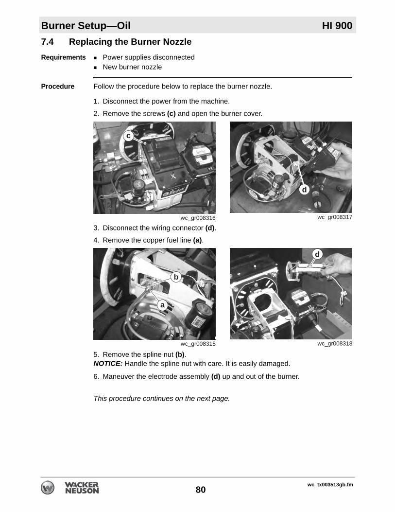
Burner Setup—Oil HI 900
7.4 Replacing the Burner NozzleRequirements Power supplies disconnectedNew burner nozzle
Procedure Follow the procedure below to replace the burner nozzle.
1. Disconnect the power from the machine.
2. Remove the screws (c) and open the burner cover.
3. Disconnect the wiring connector (d).4. Remove the copper fuel line (a).
5. Remove the spline nut (b).NOTICE: Handle the spline nut with care. It is easily damaged.
6. Maneuver the electrode assembly (d) up and out of the burner.
This procedure continues on the next page.
wc_gr008316
c
wc_gr008317
d
wc_gr008315
a
b
wc_gr008318
d
wc_tx003513gb.fm80

HI 900 Burner Setup—Oil
Continued from the previous page.7. Loosen the nut (e) and remove the clamp (f). Then, remove the head (g).
8. Unscrew the nozzle (h) from the nozzle holder.
9. When finished, check the electrodes and reposition them if necessary.
Installation Follow the procedure below to reinstall the electrode assembly.
1. Screw a new nozzle into the nozzle holder.
2. Re-install the head and the clamp.
3. Re-install the electrode assembly into the burner.
4. Reconnect the wiring.
5. Re-install the spline nut.
6. Reconnect the fuel line.
7. Close the burner cover and secure it with two screws.
Result The nozzle has now been replaced.
wc_gr008327
e
g
f
wc_gr008328
h
wc_tx003513gb.fm81

Burner Setup—Oil HI 900
7.5 Setting the “Z” Distance and Head PositionRequirements Burner removed from the machineStraight edge, and Ruler or similar measuring device
Preliminary steps
Follow the procedure below to set the “Z” distance.
1. Disconnect the copper fuel line from the nozzle assembly.
2. Loosen the spline nut (a).
3. Loosen the hex head screw (b).4. Hand tighten the acorn nut (c) so that the secondary adjusting plate (d) and the
indicator adjusting plate (e) are held together.
5. Slide the secondary adjusting plate (d) and the indicator adjusting plate (e) completely to the right.
6. Set the “Z” distance. See below.
“Z” distance Perform the procedure below to measure the “Z” distance.
1. Put a straight edge (x) on the end of the air tube.
2. Slide the nozzle assembly until the distance between the flat area of the front face of the head (y) and end of the air tube is 1-3/4 inches (44 mm).
This procedure continues on the next page.
wc_gr008322
ac d
b
e
wc_gr008321
1-3/4 in.44 mm
x
y
wc_tx003513gb.fm82

HI 900 Burner Setup—Oil
Continued from the previous page.3. Tighten the acorn nut (c).
Result The “Z” distance has now been set.
Continue by setting the head position.
Set the head position
Perform the procedure below to set the head position.
1. Slide the secondary adjusting plate (d) and the indicator adjusting plate (e) so that the indicator adjusting plate aligns with “4” on the scale.
2. Tighten the hex head screw (b).3. Tighten the spline nut.
4. Reconnect the copper fuel line.
Result The procedure to set the “Z” distance and head is now complete.
wc_gr008320
ac d
b
e
wc_tx003513gb.fm83

Burner Setup—Oil HI 900
7.6 Adjusting the Air SettingsFactory settings
Air band: 8Air shutter: 7
These settings are initial settings only. Adjust the air settings as necessary to obtain the proper smoke spot and combustion analysis values.
Background There are two parts to adjusting the air setting: 1) air band; and 2) air shutter. Adjust the air band to make large adjustments. Adjust the air shutter to make small adjustments.
Effects The air setting has the following effects on combustion.Higher O2 percentage (excess air settings) lowers soot production but raises stack temperature and reduces efficiency: lean mixture.Lower O2 percentage (inadequate air settings) increases efficiency and lowers stack temperature but may cause soot build-up: rich mixture.
Procedure Follow the procedure below to adjust the air settings.
1. Initial setting of the air damper should be performed with the machine shut down.
2. Loosen the air band locking screw (a) and the air shutter locking screw (b).
3. Using the air band position pointer (c) to determine position, rotate the air band to a higher number to increase air volume. Rotate it to a lower number to decrease air volume.
4. Using the shutter position pointer (d) to determine position, move the air shutter to a higher number on the shutter position pointer to increase air volume. Turn it to a lower number to decrease air volume.
5. After the air settings have been made, tighten the band-locking screw (a) and the shutter-locking screw (b).
Result The air settings have now been adjusted.
wc_gr008323
bc
a
d
wc_gr008324
c
d
wc_tx003513gb.fm84

HI 900 Burner Setup—Oil
7.7 Adjusting the Fuel Pressure—Oil BurnerRequirements Pressure gaugeSee Factory Settings for fuel pressure setting
Procedure Follow the procedure below to check and adjust the fuel pressure.
1. Stop the machine.
2. Open the burner access door(s) on the rear of the machine.
3. Remove the plug (not shown) from the top port (a) of the fuel pump.
4. Insert the gauge in place of the plug.
5. If your machine has a generator, start it.
6. Set the burner ON-OFF switch to the ON position. The burner will go through a pre-purge cycle. Monitor and make adjustments during the pre-purge cycle.
7. Turn the adjusting screw (b) clockwise to increase fuel pressure, counterclockwise to decrease fuel pressure.
After the correct fuel pressure has been obtained:
8. Stop the machine.
9. Remove the pressure gauge.
10.Re-install the bleeder valve.
Result The fuel pressure has now been adjusted.
wc_gr011216
a
b
wc_tx003513gb.fm85

Burner Setup—Gas HI 900
8 Burner Setup—Gas8.1 Factory Settings
HI 900
NG LP
Air damper setting 8 8
Combustion head setting 5 5
Gas manifold pressure (in. w.c.) 3.4 5.1
Orifice (mm) 3.7 2.0
Spring R6110-512 (blue) R6110-38 (pink)
wc_tx003514gb.fm86

HI 900 Burner Setup—Gas
8.2 Setting up the BurnerBackground The burner consists of several different components and subsystems. Each ofthese components or subsystems must be operating correctly for the burner to function properly.
Tools required The following tools are required to adjust the burner:High-quality combustion analyzer Smoke spot testerManometerGeneral hand tools
Mandates Adjustments made shall be done so that the machine conforms to the requirements of local, state, and federal codes and authorities. Adjustments shall be made at the job site.
When to adjust
Adjust the burner:Before operating the machine at elevations 305 m (1,000 ft) above or below the location of where the last adjustments were madeBefore starting at a new job siteAfter any burner maintenance or repair has been performedIf burner performance is in question
Procedure Follow the procedure below to set up the burner.
1. Shut down the machine.
2. Adjust the ionization probe and the electrode.(See topic 8.4)
3. Check the burner orifice.(See topic 8.5)
4. Set the air settings.(See topic 8.6)
5. Adjust the head setting.(See topic 8.7)
6. Check/set the supply gas pressure.(See topic 8.8)
7. Start the machine and the burner.
8. Check/set the burner gas pressure.(See topic 8.9)
This procedure continues on the next page.
wc_tx003514gb.fm87

Burner Setup—Gas HI 900
Continued from the previous page.9. Conduct a smoke spot test. Follow the smoke spot tester manufacturer’s instructions and the general guidelines below.
Use the access hole in the exhaust outlet.Take several samples as the heater warms.Take the final sample just before the heater reaches 71°C (160°F).
10.Analyze the combustion. Follow the combustion analyzer manufacturer’s instructions and the general guidelines below.
Use the access hole in the exhaust outlet.Take several samples as the heater warms. Take the final sample just before the heater reaches 71°C (160°F).
11.Re-adjust the air setting(s) if necessary until the smoke spot test and combustion analysis are within the following parameters:O2 content: 4–6% Smoke spot: 1 or less
Result The burner has now been set up.
wc_gr008047
wc_gr008048
wc_tx003514gb.fm88

HI 900 Burner Setup—Gas
8.3 Removing the Combustion HeadRequirements Machine shut downBurner cool
Procedure Perform the procedure below to remove the combustion head assembly.
1. Open the access doors and locate the burner (a).
2. Remove the burner assembly cover (b).3. Remove nut (c) and open the burner.
4. Make note of the position of the screw (d) then remove it.
5. Disconnect the wires (e and f).
6. Remove the combustion head (g).
wc_gr008490
a
wc_gr008489
b
wc_gr008491
c
wc_gr011217
d
wc_gr011218
f
e
wc_gr011219
g
wc_tx003514gb.fm89

Burner Setup—Gas HI 900
8.4 Adjusting the Ionization Probe and the ElectrodeRequirements Machine shut downBurner cool
Procedure Perform the procedure below to adjust both the ionizatIon probe and the electrode.
1. Shut down the machine and allow it to cool.
2. Remove the combustion head assembly. See topic Removing the Combustion Head Assembly.
3. Clean the combustion head.
4. Adjust the ionization probe (a) so that it is positioned from the mixing plate as shown.
5. Adjust the electrode (b) so that it is positioned from the mixing plate as shown.
Result Both the ionization probe and the electrode have now been adjusted.
0.039 in.
1 mm
wc_gr011220
ba
b
a
wc_tx003514gb.fm90

HI 900 Burner Setup—Gas
8.5 Changing the Burner OrificeRequirements Machine shut downMachine cool
Procedure Perform the procedure below to change the burner orifice.
1. Shut down the machine and allow it to cool.
2. Remove the combustion head assembly (a). See topic Removing the Combustion Head Assembly.
3. Unscrew the orifice (b) and remove it from the combustion head assembly.
4. Clean the existing orifice and re-install it or, install a new orifice.
5. Re-install the combustion head assembly.
6. Re-install the burner assembly cover.
Result The procedure to change the orifice is now complete.
wc_gr008496
a
wc_gr008497
b
wc_tx003514gb.fm91

Burner Setup—Gas HI 900
8.6 Checking the Burner Air Damper SettingRequirements Machine shut downBurner cool
Procedure Follow the procedure below to check the air damper setting.Note: This procedure must be performed at each new job site. The proper setting depends on environmental conditions at the job site.
1. Shut down the machine and allow it to cool.
2. Remove the burner cover.
3. Loosen the two screws (a) that secure the air adjustment plate (b).
4. Rotate the air adjustment plate so that the proper number on the air adjustment plate lines up with the setting indicator (c). See topic Factory Settings.
5. Once the air adjustment plate is set, tighten the two screws (a).
Result The air damper setting has now been checked.
b
c a
wcghi_gr005205
wc_tx003514gb.fm92

HI 900 Burner Setup—Gas
8.7 Adjusting the Head SettingRequirements Machine shut downMachine cool
Procedure Perform the procedure below to adjust the head setting.
1. Open the access doors and locate the burner (a).
2. Remove the burner assembly cover (b).3. Remove nut (c) and open the burner.
4. Loosen screw (d)5. Move the elbow (e) so that the edge of the air tube (f) is flush with the edge of
the head base (“5”).Note: Set point “5” is not marked.
6. Tighten screw (d).7. Close the burner and re-install nut (c).8. Re-install the burner cover.
Result The head setting has now been adjusted.
wc_gr008490
a
wc_gr008489
b
wc_gr008491
c
wc_gr011221
e
f
d
"5"
wc_tx003514gb.fm93
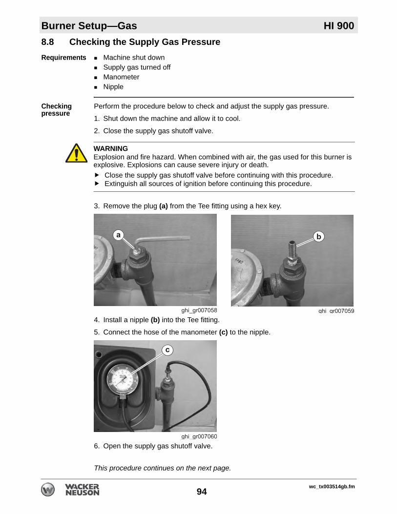
Burner Setup—Gas HI 900
8.8 Checking the Supply Gas PressureRequirements Machine shut downSupply gas turned offManometerNipple
Checking pressure
Perform the procedure below to check and adjust the supply gas pressure.
1. Shut down the machine and allow it to cool.
2. Close the supply gas shutoff valve.
3. Remove the plug (a) from the Tee fitting using a hex key.
4. Install a nipple (b) into the Tee fitting.
5. Connect the hose of the manometer (c) to the nipple.
6. Open the supply gas shutoff valve.
This procedure continues on the next page.
WARNINGExplosion and fire hazard. When combined with air, the gas used for this burner is explosive. Explosions can cause severe injury or death.
Close the supply gas shutoff valve before continuing with this procedure.Extinguish all sources of ignition before continuing this procedure.
wc_tx003514gb.fm94

HI 900 Burner Setup—Gas
Continued from the previous page.7. Check the pressure reading on the manometer. See section Technical Data for the correct pressure. Adjust the supply gas pressure as needed.
8. After the supply gas pressure has been set, turn off the supply gas.
9. Remove the manometer and the nipple.
10.Reinstall the plug.
Result The supply gas pressure has now been checked and adjusted.
wc_tx003514gb.fm95

Burner Setup—Gas HI 900
8.9 Checking and Adjusting the Burner Gas PressureRequirements Machine shut downAdequate supply gas pressure Manometer
Checking pressure
Follow the procedure below to check and adjust the burner gas pressure.
1. Open the access doors and locate the burner (a).
2. Locate the pressure test port (c).
3. Insert a small screwdriver into the pressure test port and back off the needle valve two revolutions.
4. Connect the hose of the manometer (d) to the pressure test port.
5. Start the machine.
6. With the burner firing, check the pressure reading on the manometer. See section Technical Data for the correct pressure.
This procedure continues on the next page.
wc_gr008490
a
wc_gr008499
c
wc_gr008500
d
wc_tx003514gb.fm96

HI 900 Burner Setup—Gas
Continued from the previous page.Adjusting pressure
Follow the procedure below to adjust the burner gas pressure at the regulator (e).
1. Check that the vent (g) is clean and open.
2. Remove the cap (f) from the regulator.
3. Turn the screw (e) to adjust the burner gas pressure: clockwise to increase pressurecounterclockwise to decrease pressure
Once the burner gas pressure is set:
4. Reinstall the cap.
5. Shut down the machine.
6. Remove the manometer tube from the pressure test port.
7. Tighten the needle valve.
NOTICE: Do not overtighten the needle valve. Damage to the needle valve will occur.
Result The burner gas pressure has now been checked and adjusted.
wc_gr008501
e
wc_gr008502
f
e
wc_tx003514gb.fm97

Burner Setup—Gas HI 900
8.10 Changing the Burner Type (from Oil to NG or LP)Requirements Burner Conversion Kit (contact Wacker Neuson Product Support)Licensed gas installerCombustion analyzerGas regulator (not supplied by Wacker Neuson)
Precautions You must have the proper licensing for your location.Disconnect all power to the machine.
Setting up for natural gas (NG)
Perform the following procedure to change the machine from oil burning (diesel) to natural gas (NG) burning.
Setting up for liquid propane (LP)
If using LP, perform these additional steps. Otherwise, skip to step 6.
Completing the process
Perform the following steps to complete the process.
Result The burner is now ready to operate using NG or LP.
Step Task Reference Notes1. Remove the oil burner
from the machine.Instruction sheet included with kit
Contact Wacker Neuson Product Support for more information.
2. Install the gas burner to the machine
You must be licensed for your location.
3. Install a gas regulator to the machine
Gas regulator not supplied by Wacker Neuson.
Step Task Reference Notes4. Install the appropriate
orifice and air restricting washer.
Topic 8.10 Contact Wacker Neuson Product Support for more information.
5. Install the appropriate regulator spring.
Topic 8.11
6. Adjust the supply gas pressure.
Topic 8.8 See chapter Technical Data for appropriate pressure settings.
7. Adjust the burner gas pressure.
Topic 8.9 See chapter Technical Data for appropriate pressure settings.
8. Adjust the air damper. Burner set-up procedures This setting is the same whether burning NG or LP.
9. Test the exhaust. Burner set-up procedures A combustion analyzer is needed for this step.
wc_tx003514gb.fm98

HI 900 Burner Setup—Gas
8.11 Changing the Burner from Natural Gas Burning to LP BurningRequirements Machine shut downMachine cool
Background The burner is set up at the factory to burn natural gas (NG). By changing the burner orifice and adding an air restricting washer, the burner can burn LP gas. A kit is included with new machines with the appropriate orifice and the air restricting washer.
Procedure Perform the procedure below to change the burner from NG to LP.
1. Shut down the machine and allow it to cool.2. Remove the combustion head assembly. See topic Removing the Combustion
Head Assembly.
3. Remove the natural gas orifice (e) (marked “3.7”).
4. Lift the distributor plate (h) off the combustion head assembly and place the air restricting washer (i) on the combustion head assembly as shown. Then, reinstall the distributor plate (and the air restricting washer) to the burner head with the new LP/propane orifice (marked “2.0”).
Note: The air restricting washer must be removed when changing back to NG.
5. Affix the LP gas label to the burner.
6. Reinstall the combustion head to the burner and adjust the head setting.
Result The burner is now ready to burn LP.
wc_gr008504
e
hFuel Orifice
markingNG 3.7LP 2.0
wc_gr008505
i
without washer with washer
wc_tx003514gb.fm99

Burner Setup—Gas HI 900
8.12 Changing the Gas Burner Regulator SpringRequirements Machine shut downBurner coolGas burner installed
Procedure Perform the procedure below to change the gas pressure regulator spring.
1. Locate the gas pressure regulator (d)..
2. Remove the cap (e) from the regulator.
3. Remove the screw (f) from the regulator.
4. Remove the regulator spring (g) and install a replacement spring (h).Note: The blue spring is used for NG and the pink spring is used for LP.
5. Reinstall the screw (f). 6. Adjust the gas pressure. See topic Checking and Adjusting the Burner Gas
Pressure.
7. Reinstall the cap (e) once the gas pressure is set.
Result The gas burner regulator spring has now been changed.
wc_gr008506
d
wc_tx003514gb.fm100

HI 900 Maintenance
9 Maintenance9.1 Periodic Maintenance Schedule—Oil BurnersThe table below lists basic machine maintenance. Tasks designated with check marks may be performed by the operator. Tasks designated with square bullet points require special training and equipment.
Task
Interval*(hours of service)
Daily 6 Months Yearly
--- (1000) (1200)
Check fuel level.
Clean the machine.
Inspect electrical components.
Inspect the blower motor and belt. Replace the belt if necessary.
Inspect the heat exchangers.
Replace the burner nozzle.
Replace the fuel filter.
Clean the CAD cell.
Lubricate the pillow block bearings1
Inspect and test the burner.
As needed or upon changing job sites; see chapter Burner Setup.
Inspect burner electrodes; replace burner electrodes if necessary.
Check the “Z” distance.
Check the air settings
Check the fuel pressure.
* Use whichever comes first, calendar time or service hours.1 Adjust frequency depending on work site and operating conditions.
wc_tx003515gb.fm101

Maintenance HI 900
9.2 Periodic Maintenance Schedule—Gas BurnersTask
Interval*(hours of service)
Daily 6 Months Yearly
--- (1000) (1200)
Check fuel level.
Clean the machine.
Inspect electrical components.
Inspect the blower motor and belt. Replace the belt if necessary.
Inspect the heat exchangers.
Inspect and test the burner.
As needed or upon changing job sites; see chapter Burner Setup.
Adjust the ionization probe and electrode. Replace the electrode if necessary.
Check the burner orifice.
Check the air damper setting
Check the gas pressure.
* Use whichever comes first, calendar time or service hours.
wc_tx003515gb.fm102

HI 900 Maintenance
9.3 Cleaning the MachineRequirements Machine shut downMachine cool
General cleaning
Clean the following areas to ensure proper operation.
Item Method/taskBurner Remove all dirt and debris. Ensure that the air intake area is
unobstructed.Hoses, connectors, and couplings
Wipe clean with cloth.
Trailer (if equipped) Clean with compressed air: 50 psi maximum.Covers/machine exterior
Wipe clean with cloth.
Air inlets/ouputs Remove all dirt and debris. Ensure that the air intake area is unobstructed.
wc_tx003515gb.fm103
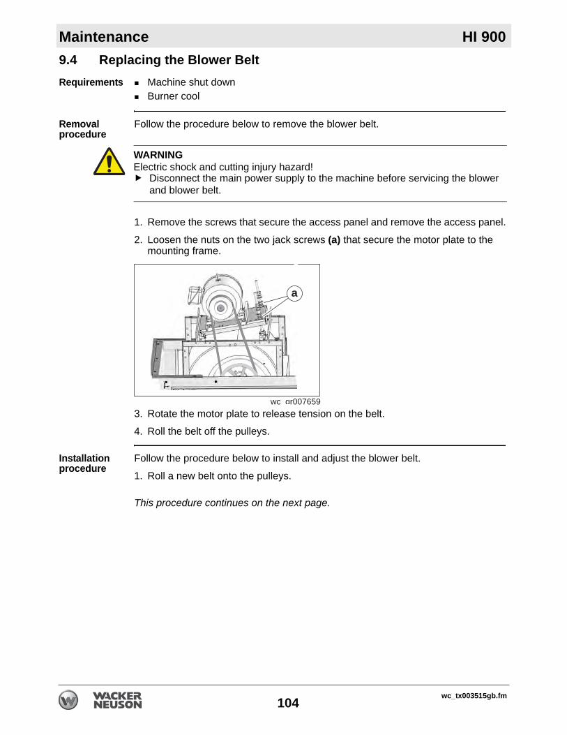
Maintenance HI 900
9.4 Replacing the Blower BeltRequirements Machine shut downBurner cool
Removal procedure
Follow the procedure below to remove the blower belt.
1. Remove the screws that secure the access panel and remove the access panel.
2. Loosen the nuts on the two jack screws (a) that secure the motor plate to the mounting frame.
3. Rotate the motor plate to release tension on the belt.
4. Roll the belt off the pulleys.
Installation procedure
Follow the procedure below to install and adjust the blower belt.
1. Roll a new belt onto the pulleys.
This procedure continues on the next page.
WARNINGElectric shock and cutting injury hazard!
Disconnect the main power supply to the machine before servicing the blower and blower belt.
wc gr007659
a
wc_tx003515gb.fm104

HI 900 Maintenance
Continued from the previous page.2. Rotate the motor plate to apply tension to the belt. A properly adjusted belt will have approximately 3/8–1/2 in. (10–13 mm) of deflection at the center of the belt when pressed with moderate pressure. Or tension by using 5–7 pounds (2.3 –3.2 kg) of pressure.
3. Tighten the nuts on the two jack screws (a) that secure the motor plate to the mounting frame. When tightening the nuts, be sure to keep the motor plate parallel with the blower housing, and the motor pulley parallel to the blower pulley.
4. Secure the access panel to the machine.
Result The procedure to replace the blower belt is now complete.
wc_gr008378
5–7 lbs.(2.3–3.2 kg)
wc_tx003515gb.fm105

Maintenance HI 900
9.5 Inspecting the Heat ExchangerIntroduction The heat exchanger consists of the combustion chamber and an attached series ofmetal tubes. As intake air flows over the hot combustion chamber and tubes, it collects heat. The heated intake air is then blown out of the supply ducts.
Reasons for inspection
A cracked or damaged heat exchanger is hazardous! Poisonous carbon monoxide gas can escape from the heat exchanger and enter the clean air stream. Combustible gases may also ignite the surrounding insulation material, causing a fire. To ensure a safe operating condition, the heat exchanger must be inspected regularly for damage.
When Inspect the heat exchanger at least twice a year as part of the regularly scheduled maintenance program.
Inspect the heat exchanger more often if any of the following conditions exist:The machine has been transported or towed over extremely rough roads or terrain.The machine / towing vehicle has been involved in an accident.The machine has been dropped.There is visible damage to the heater shell or trailer components.The burner has been improperly adjusted and is over-firing.There is doubt about whether regularly scheduled maintenance has been performed.The safety systems have been bypassed by improper or modified wiring.
NOTICE: If the machine wiring has been altered, correct the wiring before operating the machine.
Requirements Power disconnected from the machine.Machine cool. Do not inspect a hot heat exchanger.Gas fuel supply disconnected from machines with gas burners. See topic Connecting the Gas Line.Assistant to aid in the inspectionShop light or flash lightInspection mirror
This procedure continues on the next page.
DANGERAsphyxiation hazard. Gases escaping from a cracked or damaged heat exchanger contain carbon monoxide (CO). This is a poison you cannot see or smell. CO can kill you in minutes!
Do not operate the machine if it has a cracked or damaged heat exchanger.
wc_tx003515gb.fm106
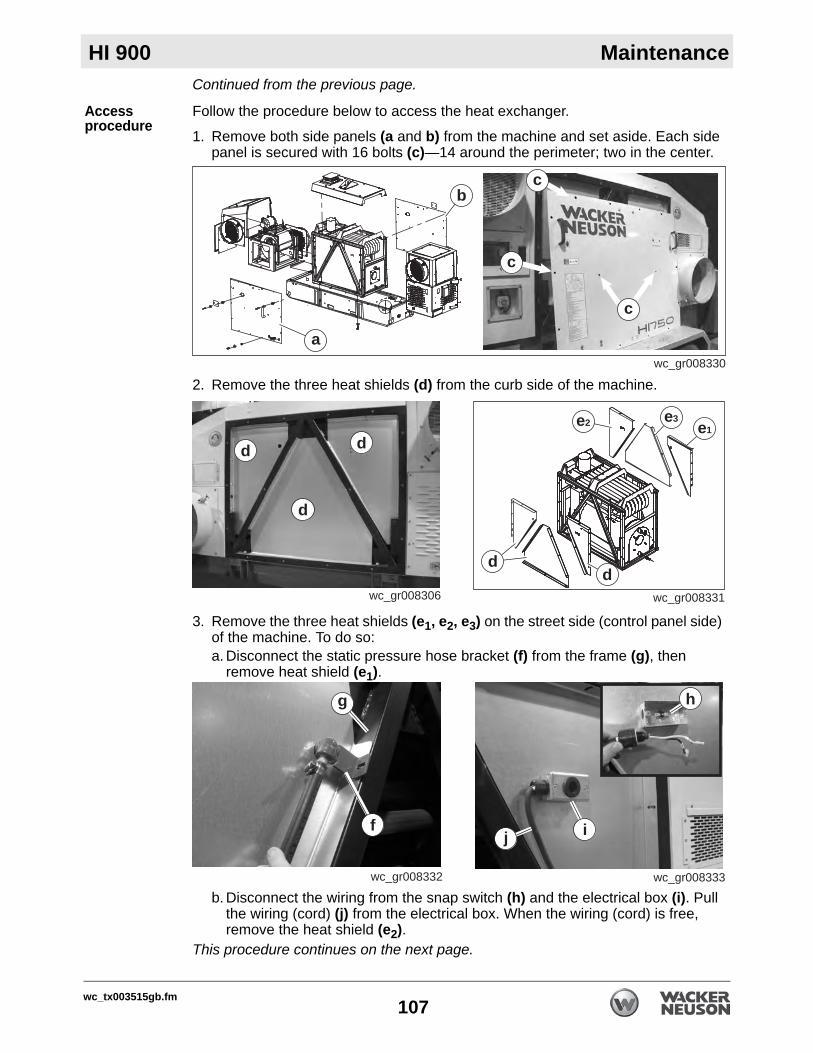
HI 900 Maintenance
Continued from the previous page.Access procedure
Follow the procedure below to access the heat exchanger.
1. Remove both side panels (a and b) from the machine and set aside. Each side panel is secured with 16 bolts (c)—14 around the perimeter; two in the center.
2. Remove the three heat shields (d) from the curb side of the machine.
3. Remove the three heat shields (e1, e2, e3) on the street side (control panel side) of the machine. To do so:a. Disconnect the static pressure hose bracket (f) from the frame (g), then
remove heat shield (e1).
b. Disconnect the wiring from the snap switch (h) and the electrical box (i). Pull the wiring (cord) (j) from the electrical box. When the wiring (cord) is free, remove the heat shield (e2).
This procedure continues on the next page.
wc_gr008330
a
b
c
c
c
wc_gr008306
d
d
d
wc_gr008331
e3e1
e2
dd
wc_gr008332
f
g
wc_gr008333
j i
h
wc_tx003515gb.fm107
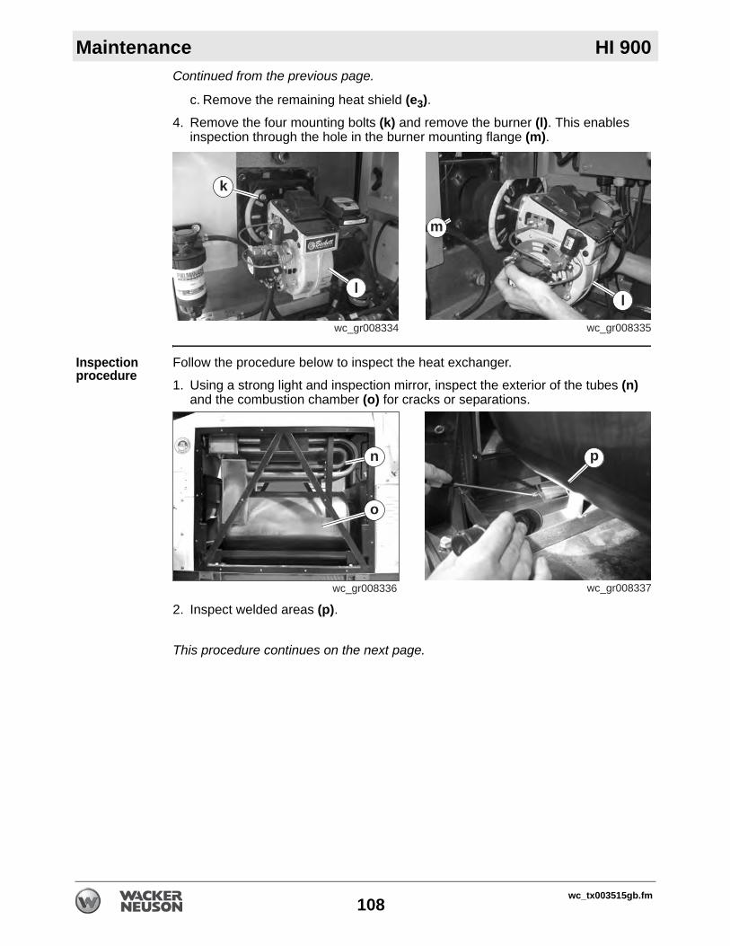
Maintenance HI 900
Continued from the previous page.c. Remove the remaining heat shield (e3).4. Remove the four mounting bolts (k) and remove the burner (l). This enables
inspection through the hole in the burner mounting flange (m).
Inspection procedure
Follow the procedure below to inspect the heat exchanger.
1. Using a strong light and inspection mirror, inspect the exterior of the tubes (n) and the combustion chamber (o) for cracks or separations.
2. Inspect welded areas (p).
This procedure continues on the next page.
wc_gr008334
k
l
wc_gr008335
l
m
wc_gr008336
n
o
wc_gr008337
p
wc_tx003515gb.fm108

HI 900 Maintenance
Continued from the previous page.3. Use the light and mirror to examine the interior of the combustion chamber for cracks or separations. Also, inspect the burner mounting flange (m) for damage.
4. Have an assistant shine the light (q) over the exterior shell of the combustion chamber while you peer through the hole in the mounting flange. Look for signs of light inside the combustion chamber.
Outcome Do not use the machine if any of the following conditions exist. Contact Wacker Neuson Product Support for assistance.
Cracks or separations are discovered in the heat exchangerSoot is visible on the exterior (air side) of the heat exchanger There are cracks or damage to the burner mounting flange
Note: Light surface rust is normal.
Reassembly Follow the procedure below to reassemble the machine after inspecting the heat exchanger.
1. Reinstall the burner.
2. Reinstall heat shield (e2).3. Reattach the static pressure hose bracket to the frame.
4. Reinstall heat shield (e1).5. Reconnect cord/wiring to the snap switch and electrical box.
6. Reinstall heat shield (e3).7. Reinstall the three curb side heat shields.
8. Reattach both side panels.
Result The heat exchanger has now been inspected.
wc_gr008338
q
wc_gr004505
m
wc_tx003515gb.fm109

Maintenance HI 900
9.6 Replacing the Burner NozzleRequirements Power supplies disconnectedNew burner nozzle
Procedure Follow the procedure below to replace the burner nozzle.
1. Disconnect the power from the machine.
2. Remove the screws (c) and open the burner cover.
3. Disconnect the wiring connector (d).4. Remove the copper fuel line (a).
5. Remove the spline nut (b).NOTICE: Handle the spline nut with care. It is easily damaged.
6. Maneuver the electrode assembly (d) up and out of the burner.
This procedure continues on the next page.
wc_gr008316
c
wc_gr008317
d
wc_gr008315
a
b
wc_gr008318
d
wc_tx003515gb.fm110

HI 900 Maintenance
Continued from the previous page.7. Loosen the nut (e) and remove the clamp (f). Then, remove the head (g).
8. Unscrew the nozzle (h) from the nozzle holder.
9. When finished, check the electrodes and reposition them if necessary.
Installation Follow the procedure below to reinstall the electrode assembly.
1. Screw a new nozzle into the nozzle holder.
2. Re-install the head and the clamp.
3. Re-install the electrode assembly into the burner.
4. Reconnect the wiring.
5. Re-install the spline nut.
6. Reconnect the fuel line.
7. Close the burner cover and secure it with two screws.
Result The nozzle has now been replaced.
wc_gr008327
e
g
f
wc_gr008328
h
wc_tx003515gb.fm111

Maintenance HI 900
9.7 Replacing the Fuel FilterRequirements Machine shut downNew fuel filter element and gasket kit
Removal NOTICE: Do not remove the fuel filter assembly from the machine unless the filter housing cap needs to be replaced. The fuel lines are permanently attached to the fuel filter assembly.
To remove the fuel filter element, carry out the following procedure:Note: In the interests of environmental protection, place a plastic sheet and a container under the machine to collect any liquid which drains off. Dispose of this liquid in accordance with local environmental protection laws.
1. Locate the fuel filter assembly (a).
2. Loosen (do not remove at this time) the bolt (b) that secures the filter housing cap (c).
3. Hold the filter housing (g) and lightly tap the bolt (b) with a hammer to break the seal between the gasket (e) and the housing (g).
4. Remove the bolt (b) and gasket (d).5. Remove the filter housing cap (c) and gasket (e).6. Pull the fuel filter element (f) out of the housing.
Installation Perform the procedure below to install the new fuel filter.
1. Remove any remaining gasket material from the filter housing cap or the housing.
2. Place the new fuel filter element (f), with exposed screen portion facing up, into the housing (g).
3. Place the new gasket (e) on the top lip of the housing.
4. Slide the new gasket (d) on the bolt (b).5. Re-install the filter housing cap (c) to the housing (g) with bolt (b).6. Reconnect the fuel lines at the quick-connect fittings (a).
Result The fuel filter has now been replaced.
wc_gr008329
a
wc_tx003515gb.fm112

HI 900 Maintenance
9.8 Cleaning the CAD CellRequirements Power supplies disconnectedClean rag
Procedure Follow the procedure below to clean the CAD cell.
1. Disconnect the power from the machine.
2. Remove the screws (c) and open the burner cover (b).
3. The CAD cell (a) is located on the under side of the cover.
4. Clean the lens of the CAD cell (a) with a clean rag.
5. Close the burner cover (b) and secure it with two screws.
Result The CAD cell has now been cleaned.
wc_gr008316
c
wc_gr008357
a
wc_gr008358
b
wc_tx003515gb.fm113

Maintenance HI 900
9.9 Storing the MachineShort-term storage1. Stop the machine.
2. Remove and store any accessories.
3. Allow the heater to cool sufficiently.
4. Fill the fuel tank if it is low. Allow space in the fuel tank for fuel expansion.
Long-term storage
1. Fill the fuel tank with stabilized fuel and operate the burner for at least fifteen minutes to ensure circulation through entire fuel system. Any brand of fuel stabilizer is acceptable.
2. Allow heater to cool sufficiently. Cover the chimney and the burner with plastic wrap or other waterproof material. This will prevent corrosive moisture build-up and blockages caused by animal nests.
3. Shut and lock all doors.
4. If the machine has a trailer, protect the trailer tires from direct sun light.
5. When removing from storage, the machine must be prepared for operation. See topic Preparing the Machine for Seasonal Operation.
wc_tx003515gb.fm114

HI 900 Maintenance
9.10 Preparing the Machine for Seasonal OperationBackground After removing the machine from long-term storage, it must be prepared foroperation. Perform the procedures below before each seasonal use.
Before powering up machine
Perform the procedures below before you power up the machine.
With machine powered up
Perform the procedures below with the machine powered up.
Item TaskMachine exterior Clean all outside surfaces
Heater and burner Remove protective coverings from chimney and burner.Remove any carbon buildup from the heater and burner assemblies.Replace the burner nozzle or orifice.Verify burner electrode position.
Controls and wiring Inspect all wires for damage, corrosion, or wear. Replace damaged wiring.Inspect all electrical components for damage, corrosion, or wear. Replace damaged electrical components.
Fuel system Replace the fuel filter element if applicable.Check gas train for leaks if applicable.
Item TaskBurner Verify fuel pump pressure if applicable.
Verify gas pressure if applicable.Verify burner combustion.
wc_tx003515gb.fm115

Maintenance HI 900
9.11 Connecting and Maintaining the BatteryBattery connections
To connect the battery:Connect the positive (+) battery cable to the battery.Connect the negative (-) battery cable to the battery.
To disconnect the battery:Stop the engine.Place all electrical switches in the OFF position.Disconnect the negative (-) battery cable from the battery.Disconnect the positive (+) battery cable from the battery.
Maintaining the battery
Follow the battery manufacturer’s maintenance recommendations.Keep battery terminals clean and connections tight.When necessary, tighten the cables and grease the cable clamps with petroleum jelly.Maintain the battery at full charge to improve cold weather starting.
Precautions Observe the following precautions to prevent serious damage to the electrical system.
Do not disconnect the battery while the machine is running.Do not attempt to run the machine without a battery. Do not attempt to jump-start the machine.In the event that the machine has a discharged battery, either replace the battery with a fully charged battery or charge the battery using an appropriate battery charger. See Technical Data for the equivalent battery specification.Dispose of waste batteries in accordance with local environmental regulations.
WARNINGExplosion hazard. Batteries can emit explosive hydrogen gas.
Keep all sparks and flames away from the battery. Do not short-circuit battery posts.
WARNINGBattery fluid is poisonous and corrosive.
In the event of ingestion or contact with skin or eyes, seek medical attention immediately.
wc_tx003515gb.fm116

HI 900 Maintenance
9.12 Storing the GensetIf the genset is to be idle for more than 120 days:
1. Change the engine oil. (Place a tag on the genset designating engine oil viscosity.)
2. Change the engine coolant.
3. Check all bolts and nuts, and tighten them as needed.
4. Remove the battery. Check the electrolyte level. Store the battery in a cool dark place.
5. Plug the exhaust tail pipe to keep out dirt, moisture, bugs, etc.
6. Clean the genset.
7. Run the engine for 5 minutes under no-load conditions every 60 days.
When returning the genset back into service:
1. Reconnect the battery.
2. Check the oil tag and change the engine oil if the oil viscosity is not appropriate for the expected temperature.
3. Remove the plug from the exhaust tail pipe.
4. Inspect the genset.
5. Clean the genset if necessary.
wc_tx003515gb.fm117

Genset Maintenance Kubota Genset
10 Genset Maintenance10.1 Periodic Maintenance ScheduleThe table below lists basic machine maintenance. Tasks designated with check marks may be performed by the operator. Tasks designated with square bullet points require special training and equipment.
Task
Interval*(hours of service)
Daily — — — — — Yearly Every 2 years
— (50) (100) (200) (400) (800) — —
Conduct a general inspection.
Check the engine oil level.
Check the engine coolant level.
Check fuel hoses and clamps.
Change engine oil.**
Clean air cleaner element.
Check battery electrolyte level.***
Check fan belt tension.
Clean fuel filter.
Check radiator hoses and clamps.
Check intake air hose.
Replace oil filter cartridge.**
Replace fuel filter cartridge.
Replace fan belt.
Check valve clearances.#
* Use whichever comes first, calendar time or service hours.** Change oil and filter after first 50 hours of operation.*** Check after first 50 hours of operation.# See Kubota dealer for service.
wc_tx001805gb.fm118
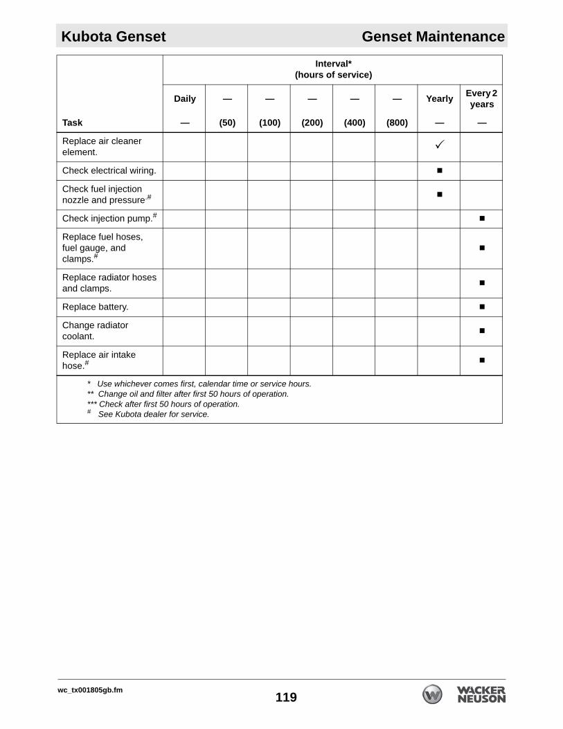
Kubota Genset Genset Maintenance
Replace air cleaner element.
Check electrical wiring.
Check fuel injection nozzle and pressure.#
Check injection pump.#
Replace fuel hoses, fuel gauge, and clamps.#
Replace radiator hoses and clamps.
Replace battery.
Change radiator coolant.
Replace air intake hose.#
Task
Interval*(hours of service)
Daily — — — — — Yearly Every 2 years
— (50) (100) (200) (400) (800) — —
* Use whichever comes first, calendar time or service hours.** Change oil and filter after first 50 hours of operation.*** Check after first 50 hours of operation.# See Kubota dealer for service.
wc_tx001805gb.fm119

Genset Maintenance Kubota Genset
10.2 Checking the Engine OilRequirements Generator shut downEngine coolMachine positioned on a level surfaceEngine oil API grade CD or higher
Determine engine oil type according to the ambient temperature.
Procedure Perform the procedure below to check the engine oil.
1. Stop the engine and allow it to cool.
2. Open the genset enclosure.
3. Remove the dipstick (2).
4. Wipe the dipstick clean and reinstall it.
5. Check the engine oil level on the end of the dipstick. It must be within range (A). 6. If the oil level is low, remove the filler plug (1) and add oil through the filler
opening until the level is within the range on the end of the dipstick.
7. Wait 5 minutes for the engine oil to drain to the oil pan and recheck the level. Add more engine oil as needed.
NOTICE: Do not operate a diesel engine when it is overfilled with engine oil. This could result in engine damage or malfunction. Drain the appropriate amount of engine oil from an over-filled diesel engine before operating it.
NOTICE: When using engine oil of a different brand from the previous brand used, drain all the previous engine oil before adding the new engine oil.
above 25°C (77°F)
0 to 25°C (32 to 77°F)
below 0°C (32°F)
SAE30 or
SAE20 or
SAE10W or
SAE10W-30SAE10W-40SAE10W-30SAE10W-40SAE10W-30SAE10W-40
wc_gr008359
wc_gr008356
1
A
2
wc_tx001805gb.fm120

Kubota Genset Genset Maintenance
10.3 Servicing the RadiatorRequirements Machine stoppedMachine coolRubber gloves
Cleaning radiator
1. Stop the engine. Allow it to cool at least 30 minutes after stopping.
2. Clean the radiator with low-pressure water. Keep the water off of electrical parts.
NOTICE: Do not use firm tools such as screwdrivers or putty knives to clean the radiator. These tools may damage the fins.
Checking coolant
Perform the procedure below to check the coolant level.
1. Stop the engine. Allow it to cool at least 30 minutes after stopping.
2. Open the genset enclosure and locate the reserve tank (1).
3. Check the level of coolant within the reserve tank. If the level of coolant is below the LOW level mark (B), add a 50/50 mixture of clean water and anti-freeze to the reserve tank until the level reaches the FULL mark (A).
NOTICE: Do not overfill the reserve tank.
Changing Perform the procedure below to change the coolant.This procedure continues on the next page.
WARNINGBurn hazard. Hot coolant spray can cause severe burns.
Allow the engine to cool before opening the radiator.
WARNINGHealth hazard. Coolant/anti-freeze can be harmful to people and pets.
Keep children and pets away from coolant/anti-freeze.When coolant/anti-freeze comes into contact with skin or clothing, wash it off immediately.
A
1
B
wc_gr008366
wc_tx001805gb.fm121

Genset Maintenance Kubota Genset
Continued from the previous page.1. Stop the engine. Allow it to cool at least 30 minutes after stopping.
2. Clean the radiator.Note: In the interests of environmental protection, place a plastic sheet and a container under the machine to collect any liquid which drains off. Dispose of this liquid in accordance with local environmental protection laws.
3. Drain the reserve tank.
4. Remove the access cover (x) from the genset enclosure.
5. Remove the rubber cover (a).
6. Slowly open the radiator cap (b) and allow any residual pressure to escape, then remove the cap.
7. With an appropriate container(s) ready to catch the coolant, open both the radiator drain plug (d) and the engine drain plug (e) simultaneously. Drain the coolant.
8. Reinstall the drain plugs.
9. Fill the radiator (c) with a 50/50 mixture of clean water and anti-freeze.
10.Reinstall the radiator cap.
11.Start the engine and allow it to run for approximately 1 minute. Stop the engine.
12.Check the amount of coolant in the radiator and add more if necessary.
This procedure continues on the next page.
wc_gr008365
x
wc_gr008364
b
a
wc_gr008367
e
d
c
wc_tx001805gb.fm122

Kubota Genset Genset Maintenance
Continued from the previous page.13.Fill the reserve tank with a 50/50 mixture of clean water and anti-freeze to the FULL mark.
14.Reinstall the rubber cover (a).
Hoses and clamps
Perform the following procedure to check the hoses and clamps.
1. Check the condition of the radiator hoses (f). Replace the hoses every two years, or if they are swollen, hardened, or cracked.
2. Check the clamps (g). Replace the clamps every two years, or if they are damaged, and whenever hoses are replaced.
3. Reinstall the access cover (x).
Result The radiator has now been serviced.
wc_gr008368
g
f
wc_tx001805gb.fm123

Genset Maintenance Kubota Genset
10.4 Checking the Fuel HosesRequirements Machine stoppedEngine cool
Procedure Follow the procedure below to check the fuel hoses.
1. Stop the engine and remove the key.
2. Open the genset enclosure.
3. Check the fuel hoses (2) and clamps (1) for damage. Replace the fuel hoses and clamps every two years, or if they are damaged.
Note: Air bleed the fuel system after each time the fuel hoses are replaced.
4. Close the genset enclosure.
Result The fuel hoses and clamps have now been adjusted.
wc_gr008370
1 1
22
wc_tx001805gb.fm124

Kubota Genset Genset Maintenance
10.5 Changing the Engine OilRequirements Engine warmAppropriate container to hold used engine oilFresh, clean engine oil
Determine engine oil type according to the ambient temperature.
Draining oil Perform the procedure below to change the engine oil.
Note: In the interests of environmental protection, place a plastic sheet and a container under the machine to collect any liquid which drains off. Dispose of this liquid in accordance with local environmental protection laws.
1. Operate the genset until warm, then stop the engine.
2. Remove the drain plug (3) and drain the used engine oil. Dispose of used engine oil in accordance with local environmental protection laws.
Filling 1. Check the gasket on the drain plug. Replace it if necessary. Then, reinstall the drain plug.
2. Remove the filler plug (1) and add engine oil through the filler opening until the level is within the range (A) on the end of the dipstick (2).
3. Wait 5 minutes for the engine oil to drain to the oil pan and recheck the level. Add more engine oil as needed.
4. Reinstall filler plug.
WARNINGMost used oil contains small amounts of materials that can cause cancer and other health problems if inhaled, ingested, or left in contact with skin for prolonged periods of time.
Take steps to avoid inhaling or ingesting used engine oil. Wash skin thoroughly after exposure to used engine oil.
above 25°C (77°F)
0 to 25°C (32 to 77°F)
below 0°C (32°F)
SAE30 or
SAE20 or
SAE10W or
SAE10W-30SAE10W-40SAE10W-30SAE10W-40SAE10W-30SAE10W-40
wc_gr008359
wc_gr008360
3wc_gr008356
1
A
2
wc_tx001805gb.fm125

Genset Maintenance Kubota Genset
10.6 Servicing the Air CleanerRequirements Machine stoppedNew elements if necessary
Procedure Perform the procedure below to service the air cleaner.
1. Stop the engine.
2. Open the evacuator valve (6) weekly to remove large particles of dirt.
Air cleaner assembly
3. Remove the air cleaner assembly (7) from the engine.
4. Disassemble the air cleaner assembly. Avoid touching the elements except when cleaning them.
5. Wipe out the inside of the air cleaner body (1) and the cover (4).
Primary element
6. Remove the primary element (3) and blow low-pressure (205 kPa (30 psi)) compressed air through it from the inside out.
7. If the primary element is heavily soiled, soak it for 15 minutes in warm soapy water. Rinse it in clean water and allow it to air dry.
8. Inspect the primary element. Replace the primary element every six cleanings, or if it is damaged, or if it is heavily stained.
Secondary element
9. To avoid possible engine damage, do not remove the secondary element (2) except when cleaning it.
10.To clean the secondary element (3), remove it and blow low-pressure (205 kPa (30 psi)) compressed air through it from the inside out.
11.If the secondary element is heavily soiled, wash it with Donaldson ND-1500 filter cleaner or an equivalent cleaner.
12.Inspect the secondary element. Replace the secondary element yearly or if it is damaged.
Result The air cleaner has now been serviced. Reassemble it with the cover (4) pointing (5) in the direction shown.
wc_gr008363
7
5
wc_gr008362
1
2 3 6
4
45
wc_tx001805gb.fm126

Kubota Genset Genset Maintenance
10.7 Checking Battery Electrolyte LevelRequirements Machine stoppedEngine coolDistilled waterRubber gloves
Procedure Follow the procedure below to check the battery electrolyte level.
1. Stop the engine and remove the key.
2. Open the genset enclosure.
3. Locate the battery (a).
4. Remove the vent caps (b).
This procedure continues on the next page.
WARNINGExplosion hazard. Batteries can emit explosive hydrogen gas.
Keep all sparks and flames away from the battery. Do not short-circuit battery posts.
WARNINGBattery fluid is poisonous and corrosive.
In the event of ingestion or contact with skin or eyes, seek medical attention immediately.
wc_gr008372
a
b
wc_tx001805gb.fm127

Genset Maintenance Kubota Genset
Continued from the previous page.5. Check the electrolyte level in each cell. The electrolyte level should be at the bottom of the vent wells (B).
6. Fill any cell that is low with distilled water until the battery’s fluid level is at the proper level (B).
7. Reinstall the vent caps.
Result The electrolyte level has now been checked.
wc_gr008373
A B CToo low Proper Too high
A
C
wc_tx001805gb.fm128

Kubota Genset Genset Maintenance
10.8 Adjusting the Fan Belt TensionRequirements Machine stoppedEngine cool
Procedure Follow the procedure below to adjust the fan belt tension.
1. Stop the engine and remove the key.
2. Open the genset enclosure.
3. Check the belt for cracks and damage. Replace the belt if it is damaged.
4. Apply moderate thumb pressure to the belt (1) between the pulleys. There should be approximately 12–14 mm (0.47–0.50 in.) of deflection (A). To adjust the tension, continue.
5. Loosen the locknut (3).6. Turn the adjust nut (2) to obtain the proper belt tension.
7. Retighten the locknut.
Result The belt tension is now adjusted.
wc_gr008369
3
2
1
A
wc_tx001805gb.fm129

Genset Maintenance Kubota Genset
10.9 Cleaning the Fuel Filter and Filter HousingRequirements Machine stoppedEngine cool
Procedure Follow the procedure below to clean the fuel filter and the filter housing.
1. Stop the engine and remove the key.
2. Open the genset enclosure and locate the fuel filter.
3. Place the fuel valve in the CLOSED position (A).
4. Remove the filter housing (2) from the cover (1). 5. Rinse the cover with diesel fuel.
6. Remove the fuel filter element and rinse it with diesel fuel. (Replace the fuel filter element every 200 hours of operation.)
7. Rinse the filter housing with diesel fuel.
8. Reinstall the fuel filter element.
9. Reassemble the filter housing to the cover.
10.Air bleed the fuel system. See topic Bleeding Air from the Generator Fuel System.
Result The fuel filter and filter housing have now been cleaned.
12
A
wc_gr008371
wc_tx001805gb.fm130

Kubota Genset Genset Maintenance
10.10 Replacing the Engine Oil FilterRequirements Machine stoppedNew engine oil filter
Procedure Perform the procedure below to change the engine oil filter.Note: In the interests of environmental protection, place a plastic sheet and a container under the machine to collect any liquid which drains off. Dispose of this liquid in accordance with local environmental protection laws.
1. Stop the engine.
2. Remove the old filter (1) with a filter wrench.
3. Apply a film of new engine oil to the gasket of the new oil filter (2). 4. Screw the new oil filter onto the engine by hand. Tighten it firmly by hand. Do
not use a wrench to tighten the oil filter, it may be damaged.
5. Check the engine oil level and add engine oil as necessary.
Result The engine oil filter has now been replaced.
WARNINGMost used oil contains small amounts of materials that can cause cancer and other health problems if inhaled, ingested, or left in contact with skin for prolonged periods of time.
Take steps to avoid inhaling or ingesting used engine oil. Wash skin thoroughly after exposure to used engine oil.
wc_gr008361
1
2
wc_tx001805gb.fm131

Genset Maintenance Kubota Genset
10.11 Checking Air Inlet HoseRequirements Machine stoppedEngine cool
Procedure Follow the procedure below to check the air inlet hose.
1. Stop the engine and remove the key.
2. Open the genset enclosure.
3. Locate the air inlet hose (a).
4. Check the air inlet hose for proper connection, cracks or other air leaks that may allow the engine to draw air that is not filtered. Replace the air inlet hose every two years or if it is damaged.
Result The air inlet hose has now been checked.
wc_gr008374
a
wc_tx001805gb.fm132

Kubota Genset Genset Maintenance
10.12 Bleeding Air from the Generator Fuel SystemWhen Bleeding air from the generator fuel system is required:after the fuel filter and fuel lines have been detached and reinstalledafter the fuel tank has run drybefore starting the engine after long-term storage
Procedure Follow the procedure below to bleed air from the fuel system.
1. Fill the fuel tank completely.
2. Raise the front of the machine by fully extending the tongue jack.
3. Locate the fuel filter (a).4. Open the fuel filter valve (b) by rotating the lever clockwise.
5. Loosen, but do not remove, the fuel filter air vent plug (c). Fuel bubbles will appear.
6. Tighten the fuel filter air vent plug when fuel stops bubbling.
7. Loosen, but do not remove, the fuel pump air vent plug (d). Fuel bubbles will appear.
8. Tighten the fuel pump air vent plug when fuel stops bubbling.
9. Close the fuel filter valve by rotating the lever counterclockwise.
10.Return the machine to level by lowering the tongue jack.
Result Air has now been bled from the fuel system. Proceed with normal operation.
WARNINGBurn and fire hazards. Engine components become very hot during operation. Fuel spilled on a hot engine may ignite.
Allow the engine to cool before bleeding air from the fuel system.
wc_gr007658
a
dc
a
b
wc_tx001805gb.fm133

Basic Troubleshooting HI 900
11 Basic Troubleshooting11.1 Machines with Oil Burners
Problem/Symptom Reason Remedy
The burner does not start
Faulty cable or power supply Check cable and power supply.
One or both of the high-temperature reset switches has tripped.
Press reset pushbutton(s).
The burner starts, the flame does not ignite, and the unit locks out
No fuel Fill fuel tank.
Worn burner nozzle Replace burner nozzle.
Faulty electrodes Replace electrodes.
Faulty cad cell Call Wacker Neuson Product Support.
Faulty burner control Call Wacker Neuson Product Support.
The burner starts, flame ignites, but the unit locks out
Incorrect fuel pressure Increase fuel pressure.
Worn burner nozzle Replace burner nozzle.
Incorrect air adjustment Readjust air supply.
Faulty cad cell Call Wacker Neuson Product Support.
Faulty burner control Call Wacker Neuson Product Support.
Faulty connection to neutral Correct faulty connection.
Combustion is poor or noisy
Lack of fresh air to burner Ensure that there is an adequate air supply.If the problem persists, call Wacker Neuson Product Support.
Excessive blower noise
Faulty motor bearings Replace motor bearings.
Mounting base not secure Tighten mounting hardware.
Misaligned pulleys Adjust alignment.
Damaged wheel Replace wheel.
Incorrect belt tension Check tension.
Motor overheating Incorrect belt tension Adjust belt tension.
Over or under voltage Check power supply.
Fan inoperative Circuit breaker tripped Reset circuit breaker.
Loose or disconnected wiring Check wiring and repair as needed.
Faulty motor Replace motor.
Broken belt Replace belt.
wc_tx003517gb.fm134

HI 900 Basic Troubleshooting
11.2 Machines with Gas BurnersProblem/Symptom Reason Remedy
The burner goes to lockout after the pre-purge period because the flame does not ignite.
Air has not been evacuated from the gas lines.
Check the gas train for leaks.
The gas valve is passing too little gas.
Adjust the gas valve.
The ignition spark is irregular or not present.
Adjust or replace the electrode.
The gas valve is faulty. Replace the gas valve.
The burner does not start when there is a call for heat.
The air pressure switch is faulty.
Replace the air pressure switch.
There is no gas, or there is insufficient pressure in the supply lines to activate the optional gas pressure switch.
Check the gas supply.
There is a blown buss fuse. Check / replace the fuse.
The low voltage contacts or the low voltage relay are faulty.
Check / replace the low voltage relay.
The burner does not go through prepurge, ignition is established, the burner fires for 2 seconds, then goes to lockout.
The air pressure switch does not change from normally closed to normally open contacts. This condition exists due to insufficient pressure in the air tube.
Move the head towards zero (0) on the stop gate.
The burner goes through prepurge, ignition is established, the burner fires for 2 seconds, then goes to lockout.
The flame rod is faulty or has shorted to ground.
Replace the flame rod.
Polarity is reversed or the earth ground is not connected properly.
Check / rectify the wiring.
The ionization current is weak (lower than 5 micro Amps).
Replace the ionization probe.
Excessive blower noise Faulty motor bearings Replace the motor bearings.
Mounting base not secure Tighten mounting hardware.
Misaligned pulleys Adjust the alignment.
Damaged wheel Replace the wheel.
Incorrect belt tension Check belt tension.
Motor overheating Incorrect belt tension Adjust the belt tension.
Over or under voltage Check the power supply.
Fan inoperative Circuit breaker tripped Reset the circuit breaker.
Loose or disconnected wiring Check the wiring and repair as needed.
Faulty motor Replace the motor.
Broken belt Replace the belt.
wc_tx003517gb.fm135

Technical Data HI 900
12 Technical Data12.1 Machine
NG/LP Diesel
Item Number:520001416152000141635200014164
520001415852000141595200014160
(shore power)
52000141655200014166(mobile, with generator)
HI 900
Dimensions LxWxH in.(cm)
139x47x66(353x119x166)
139x47x77(353x119x196)
197x61x101(500x155x255)
Weight: with fuel without fuel
lbs.(kg)
—2300 (1050)
2567 (1167)3400 (1550)
4925 (2240)4092 (1860)
Fuel input BTU/hr 850,000 890,000
Net burner heat output
BTU/hr 705,500 738,700 738,700
Efficiency % 83
Air output volume cfm 6447
Static pressure in. w.c. 2
Power requirements VAC,Amps,
Hz;Plug
115, 15, 60; NEMA 5-15and
230, 30, 60; NEMA L6-30
Blower motor VAC,Amp 230, 13
Vent pipe diameter (nominal)
in.(cm) 8 (20.32)
Burner nozzle (solid spray)
gph — 5.5 60° B
Fuel pressure psig(bar) — 140 (9.65)
Fuel consumption gph(lph)
LP: 8.19 (35.1)
NG: 850 cfh (24.03 m3/h)
6.4
Air shutter / damper(factory setting) 8 7
Fuel capacity gal. (l) — 119 (449.7)
Hours of operation per tank
hrs — 16.9
wc_td000582gb.fm136

HI 900 Technical Data
* Longer run times are achieved when using the machine indoors.
Maximum return duct length
in. x ft.(mm x m)
2: 20 x 110(2: 508 x 33.5)
Maximum supply duct length
in. x ft(mm x m)
3: 16 x 55(3: 406 x 16.8)
Orifice mm NG: 3.7LP: 2.0 —
Supply fuel pressure (max.)
in. w.c. NG: 7–14LP: 8–14 —
Combustion head setting 5 —
Manifold pressure (operating)
in. w.c. NG: 3.4LP: 5.1 —
NG/LP Diesel
Item Number:520001416152000141635200014164
520001415852000141595200014160
(shore power)
52000141655200014166(mobile, with generator)
wc_td000582gb.fm137

Technical Data HI 900
12.2 GensetModel Kubota GL7000
Frequency Hz 60
Rated output kVAkW
6.56.5
Rated voltage V 120 / 240
Rated amperage A 54.2 / 27.1
Phase & wire — 1 Ø / 4-wire
Power factor % 100
Number of poles — 2
Insulation Class B
Voltage regulation % 5 (no load to full load)
Type of coupling — Direct
Engine model — Z482
Design — Vertical, water-cooled, 4-cycle
Number of cylinders — 4
Bore and stroke mm (in.) 67 x 68 (2.6 x 2.7)
Displacement l (in3) 0.479 (29.2)
Engine speed rpm 3600
Lubricating oil — API service class CD or higher
Oil capacity l (qt) 2.2 (2.3)
Coolant capacity l (gal) 3.7 (0.98)
Battery model (V x Ah) 38B20R (12V x 28 Ah)
L x W x H mm (in.) 1066 x 618 x 698(42.o x 24.3 x 27.5)
wc_td000582gb.fm138

HI 900 Technical Data
12.3 TrailerItem NumberModel
5200014165HI 900 DGM
5200014166HI 900 DGM
GAWR(Gross Axle Weight Rating)
kg(lb)
1588(3500)
Rim mm(in.)
381 x 152(15 x 6.0)
Tire code — ST225/75D15D
Tire pressure kPa(psi)
448(65)
Lug nut torque Nmft-lbs
122–135(90–100)
GVWR (Gross Vehicle Weight Rating)
kg(lb)
3175(7000)
Brake type — Electric Surge
Brake fluid type for surge brakes — — DOT 3 or 4
Maximum towing speed km/h(MPH)
72(45)
wc_td000582gb.fm139

Technical Data HI 900
Noteswc_td000582gb.fm140

Tire Safety Information
Tire Safety InformationIntroduction to Tire Safety InformationFederal Regulation 49 CFR 575 requires trailer manufacturers to include certain tire information in the Owner’s Manuals for the trailers they manufacture. This regulation requires that the information be in the English language. This chapter includes all the information required by Federal Regulation 49 CFR 575.
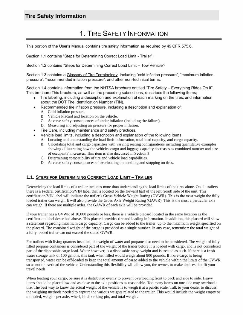
Tire Safety Information
1. TIRE SAFETY INFORMATION
This portion of the
Section 1.1 contains - Trailer .
Section 1.2 contains mit Tow Vehicle .
Section 1.3 contains a Glossary of Tire Terminology-technical terms.
Section 1.4 contains information from the NHTSA brochure entitled “Tire Safety – Everything Rides On It”.This brochure This brochure, as well as the preceding subsections, describes the following items;
Tire labeling, including a description and explanation of each marking on the tires, and information about the DOT Tire Identification Number (TIN). Recommended tire inflation pressure, including a description and explanation of:A. Cold inflation pressure.B. Vehicle Placard and location on the vehicle.C. Adverse safety consequences of under inflation (including tire failure).D. Measuring and adjusting air pressure for proper inflation.Tire Care, including maintenance and safety practices.Vehicle load limits, including a description and explanation of the following items:A. Locating and understanding the load limit information, total load capacity, and cargo capacity.B. Calculating total and cargo capacities with varying seating configurations including quantitative examples
showing / illustrating how the vehicles cargo and luggage capacity decreases as combined number and size
C. Determining compatibility of tire and vehicle load capabilities.D. Adverse safety consequences of overloading on handling and stopping on tires.
1.1. STEPS FOR DETERMINING CORRECT LOAD LIMIT TRAILER
Determining the load limits of a trailer includes more than understanding the load limits of the tires alone. On all trailersthere is a Federal certification/VIN label that is located on the forward half of the left (road) side of the unit. This
loaded trailer can weigh. It will also provide the Gross Axle Weight Rating (GAWR). This is the most a particular axle can weigh. If there are multiple axles, the GAWR of each axle will be provided.
If your trailer has a GVWR of 10,000 pounds or less, there is a vehicle placard located in the same location as the certification label described above. This placard provides tire and loading information. In addition, this placard will show a statement regarding maximum cargo capacity. Cargo can be added to the trailer, up to the maximum weight specified onthe placard. The combined weight of the cargo is provided as a single number. In any case, remember: the total weight of a fully loaded trailer can not exceed the stated GVWR.
For trailers with living quarters installed, the weight of water and propane also need to be considered. The weight of fully filled propane containers is considered part of the weight of the trailer before it is loaded with cargo, and is not consideredpart of the disposable cargo load. Water however, is a disposable cargo weight and is treated as such. If there is a fresh water storage tank of 100 gallons, this tank when filled would weigh about 800 pounds. If more cargo is being transported, water can be off-loaded to keep the total amount of cargo added to the vehicle within the limits of the GVWR so as not to overload the vehicle. Understanding this flexibility will allow you, the owner, to make choices that fit your travel needs.
When loading your cargo, be sure it is distributed evenly to prevent overloading front to back and side to side. Heavy items should be placed low and as close to the axle positions as reasonable. Too many items on one side may overload a tire. The best way to know the actual weight of the vehicle is to weigh it at a public scale. Talk to your dealer to discuss the weighing methods needed to capture the various weights related to the trailer. This would include the weight empty or unloaded, weights per axle, wheel, hitch or king-pin, and total weight.

Tire Safety Information
Excessive loads and/or underinflation cause tire overloading and, as a result, abnormal tire flexing occurs. This situation can generate an excessive amount of heat within the tire. Excessive heat may lead to tire failure. It is the air pressure that enables a tire to support the load, so proper inflation is critical. The proper air pressure may be found on the certification/VIN label and/or on the Tire Placard. This value should never exceed the maximum cold inflation pressure stamped on the tire.
1.1.1. TRAILERS 10,000 POUNDS GVWR OR LESS
Tire and Loading Information Placard Figure 1-1
1.placard. See figure 1-1.
2. This figure equals the available amount of cargo and luggage load capacity. 3. Determine the combined weight of luggage and cargo being loaded on the vehicle. That weight may not
safely exceed the available cargo and luggage load capacity.
attached (Certification) label at the left front of the trailer.
1.1.2. TRAILERS OVER 10,000 POUNDS GVWR (NOTE: THESE TRAILERS ARE NOT REQUIRED TO HAVE A TIRE INFORMATION PLACARD ON THE VEHICLE)
1. Determine the empty weight of your trailer by weighing the trailer using a public scale or other means. This step does not have to be repeated.
2. Locate the 3. Subtract the empty weight of your trailer from the GVWR stated on the VIN label. That weight is the
maximum available cargo capacity of the trailer and may not be safely exceeded.
1.2. STEPS FOR DETERMINING CORRECT LOAD LIMIT TOW VEHICLE
1.
2. Determine the combined weight of the driver and passengers who will be riding in your vehicle.3. Subtract the combined weight of the driver and passengers from XXX kilograms or XXX pounds.4.
amount equals 1400 lbs. and there will be five 150 lb. passengers in your vehicle, the amount of available cargo and luggage capacity is 650 lbs. (1400-750 (5 x 150) = 650 lbs.).
5. Determine the combined weight of luggage and cargo being loaded on the vehicle. That weight may not safely exceed the available cargo and luggage capacity calculated in Step # 4.
6. If your vehicle will be towing a trailer, load from your trailer will be transferred to your vehicle. Consult the educes the available cargo and luggage
capacity of your vehicle.
1.3. GLOSSARY OF TIRE TERMINOLOGY
Accessory weightThe combined weight (in excess of those standard items which may be replaced) of automatic transmission, power steering, power brakes, power windows, power seats, radio and heater, to the extent that these items are available as factory-installed equipment (whether installed or not).

Tire Safety Information
BeadThe part of the tire that is made of steel wires, wrapped or reinforced by ply cords and that is shaped to fit the rim.Bead separationThis is the breakdown of the bond between components in the bead.
Bias ply tireA pneumatic tire in which the ply cords that extend to the beads are laid at alternate angles substantially less than 90 degrees to the centerline of the tread.
CarcassThe tire structure, except tread and sidewall rubber which, when inflated, bears the load.
ChunkingThe breaking away of pieces of the tread or sidewall.
Cold inflation pressureThe pressure in the tire before you drive.CordThe strands forming the plies in the tire.
Cord separationThe parting of cords from adjacent rubber compounds.
CrackingAny parting within the tread, sidewall, or inner liner of the tire extending to cord material.
CTA pneumatic tire with an inverted flange tire and rim system in which the rim is designed with rim flanges pointed radially inward and the tire is designed to fit on the underside of the rim in a manner that encloses the rim flanges inside the air cavity of the tire.
Curb weightThe weight of a motor vehicle with standard equipment including the maximum capacity of fuel, oil, and coolant, and, if so equipped, air conditioning and additional weight optional engine.
Extra load tireA tire designed to operate at higher loads and at higher inflation pressures than the corresponding standard tire.
GrooveThe space between two adjacent tread ribs.
Gross Axle Weight RatingThe maximum weight that any axle can support, as published on the Certification / VIN label on the front left side of the trailer. Actual weight determined by weighing each axle on a public scale, with the trailer attached to the towing vehicle.
Gross Vehicle Weight RatingThe maximum weight of the fully loaded trailer, as published on the Certification / VIN label. Actual weight determined by weighing trailer on a public scale, without being attached to the towing vehicle.
Hitch WeightThe downward force exerted on the hitch ball by the trailer coupler.
InnerlinerThe layer(s) forming the inside surface of a tubeless tire that contains the inflating medium within the tire.
Innerliner separationThe parting of the innerliner from cord material in the carcass.

Tire Safety Information
Intended outboard sidewallThe sidewall that contains a white-wall, bears white lettering or bears manufacturer, brand, and/or model name molding that is higher or deeper than the same molding on the other sidewall of the tire or the outward facing sidewall of an asymmetrical tire that has a particular side that must always face outward when mounted on a vehicle.Light truck (LT) tireA tire designated by its manufacturer as primarily intended for use on lightweight trucks or multipurpose passenger vehicles.
Load ratingThe maximum load that a tire is rated to carry for a given inflation pressure.
Maximum load ratingThe load rating for a tire at the maximum permissible inflation pressure for that tire.
Maximum permissible inflation pressureThe maximum cold inflation pressure to which a tire may be inflated.
Maximum loaded vehicle weightThe sum of curb weight, accessory weight, vehicle capacity weight, and production options weight.
Measuring rimThe rim on which a tire is fitted for physical dimension requirements.
Pin WeightThe downward force applied to the 5th wheel or gooseneck ball, by the trailer kingpin or gooseneck coupler.
Non-pneumatic rimA mechanical device which, when a non-pneumatic tire assembly incorporates a wheel, supports the tire, and attaches, either integrally or separably, to the wheel center member and upon which the tire is attached.
Non-pneumatic spare tire assemblyA non-pneumatic tire assembly intended for temporary use in place of one of the pneumatic tires and rims that are fitted to a passenger car in compliance with the requirements of this standard.
Non-pneumatic tireA mechanical device which transmits, either directly or through a wheel or wheel center member, the vertical load and tractive forces from the roadway to the vehicle, generates the tractive forces that provide the directional control of the vehicle and does not rely on the containment of any gas or fluid for providing those functions.
Non-pneumatic tire assemblyA non-pneumatic tire, alone or in combination with a wheel or wheel center member, which can be mounted on a vehicle.
Normal occupant weightThis means 68 kilograms (150 lbs.) times the number of occupants specified in the second column of Table I of 49 CFR 571.110.
Occupant distribution The distribution of occupants in a vehicle as specified in the third column of Table I of 49 CFR 571.110.
Open spliceAny parting at any junction of tread, sidewall, or innerliner that extends to cord material.
Outer diameterThe overall diameter of an inflated new tire.
Overall widthThe linear distance between the exteriors of the sidewalls of an inflated tire, including elevations due to labeling, decorations, or protective bands or ribs.

Tire Safety Information
Ply A layer of rubber-coated parallel cords.
Ply separation A parting of rubber compound between adjacent plies.
Pneumatic tire A mechanical device made of rubber, chemicals, fabric and steel or other materials, that, when mounted on an automotive wheel, provides the traction and contains the gas or fluid that sustains the load.
Production options weight The combined weight of those installed regular production options weighing over 2.3 kilograms (5 lbs.) in excess of those standard items which they replace, not previously considered in curb weight or accessory weight, including heavy duty brakes, ride levelers, roof rack, heavy duty battery, and special trim.
Radial ply tire A pneumatic tire in which the ply cords that extend to the beads are laid at substantially 90 degrees to the centerline of the tread.
Recommended inflation pressure This is the inflation pressure provided by the vehicle manufacturer on the Tire Information label and on the Certification / VIN tag.
Reinforced tire A tire designed to operate at higher loads and at higher inflation pressures than the corresponding standard tire.
Rim A metal support for a tire or a tire and tube assembly upon which the tire beads are seated.
Rim diameter This means the nominal diameter of the bead seat.
Rim size designation This means the rim diameter and width.
Rim type designation rim by style or code.
Rim width This means the nominal distance between rim flanges.
Section width The linear distance between the exteriors of the sidewalls of an inflated tire, excluding elevations due to labeling, decoration, or protective bands.
Sidewall That portion of a tire between the tread and bead.
Sidewall separation The parting of the rubber compound from the cord material in the sidewall.
Special Trailer (ST) tireThe "ST" is an indication the tire is for trailer use only.
Test rim The rim on which a tire is fitted for testing, and may be any rim listed as appropriate for use with that tire.
Tread That portion of a tire that comes into contact with the road.

Tire Safety Information
Tread ribA tread section running circumferentially around a tire.
Tread separationPulling away of the tread from the tire carcass.
Treadwear indicators (TWI)The projections within the principal grooves designed to give a visual indication of the degrees of wear of the tread.
Vehicle capacity weightThe rated cargo a
Vehicle maximum load on the tireThe load on an individual tire that is determined by distributing to each axle its share of the maximum loaded vehicle weight and dividing by two.
Vehicle normal load on the tireThe load on an individual tire that is determined by distributing to each axle its share of the curb weight, accessory weight, and normal occupant weight (distributed in accordance with Table I of CRF 49 571.110) and dividing by 2.
Weather sideThe surface area of the rim not covered by the inflated tire.
Wheel center memberIn the case of a non-pneumatic tire assembly incorporating a wheel, a mechanical device which attaches, either integrally or separably, to the non-pneumatic rim and provides the connection between the non-pneumatic rim and the vehicle; or, in the case of a non-pneumatic tire assembly not incorporating a wheel, a mechanical device which attaches, either integrally or separably, to the non-pneumatic tire and provides the connection between tire and the vehicle.
Wheel-holding fixtureThe fixture used to hold the wheel and tire assembly securely during testing.
1.4. TIRE SAFETY - EVERYTHING RIDES ON IT
The National Traffic Safety Administration (NHTSA) has published a brochure (DOT HS 809 361) that discusses all aspects of Tire Safety, as required by CFR 575.6. This brochure is reproduced in part below. It can be obtained and downloaded from NHTSA, free of charge, from the following web site:
http://www.nhtsa.dot.gov/cars/rules/TireSafety/ridesonit/tires_index.html
Studies of tire safety show that maintaining proper tire pressure, observing tire and vehicle load limits (not carrying more weight in your vehicle than your tires or vehicle can safely handle), avoiding road hazards, and inspecting tires for cuts, slashes, and other irregularities are the most important things you can do to avoid tire failure, such as tread separation or blowout and flat tires. These actions, along with other care and maintenance activities, can also:
Improve vehicle handling Help protect you and others from avoidable breakdowns and accidents Improve fuel economy Increase the life of your tires.
This booklet presents a comprehensive overview of tire safety, including information on the following topics:Basic tire maintenance Uniform Tire Quality Grading System Fundamental characteristics of tires

Tire Safety Information
y p
Use this information to make tire safety a regular part of your vehicle maintenance routine. Recognize that the time you spend is minimal compared with the inconvenience and safety consequences of a flat tire or other tire failure.
1.5. SAFETY FIRST BASIC TIRE MAINTENANCE
Properly maintained tires improve the steering, stopping, traction, and load-carrying capability of your vehicle. Underinflated tires and overloaded vehicles are a major cause of tire failure. Therefore, as mentioned above, to avoid flat tires and other types of tire failure, you should maintain proper tire pressure, observe tire and vehicle load limits, avoid road hazards, and regularly inspect your tires.
1.5.1. FINDING YOUR VEHICLE'S RECOMMENDED TIRE PRESSURE AND LOAD LIMITS
Tire information placards and vehicle certification labels contain information on tires and load limits. These labels indicate the vehicle manufacturer's information including:
Recommended tire size Recommended tire inflation pressure Vehicle capacity weight (VCW the maximum occupant and cargo weight a vehicle is designed to carry) Front and rear gross axle weight ratings (GAWR the maximum weight the axle systems are designed to carry).
Both placards and certification labels are permanently attached to the trailer near the left front.
1.5.2. UNDERSTANDING TIRE PRESSURE AND LOAD LIMITS
Tire inflation pressure is the level of air in the tire that provides it with load-carrying capacity and affects the overall performance of the vehicle. The tire inflation pressure is a number that indicates the amount of air pressure measured in pounds per square inch (psi) a tire requires to be properly inflated. (You will also find this number on the vehicle information placard expressed in kilopascals (kpa), which is the metric measure used internationally.)
Manufacturers of passenger vehicles and light trucks determine this number based on the vehicle's design load limit, that is, the greatest amount of weight a vehicle can safely carry and the vehicle's tire size. The proper tire pressure for your vehicle is referred to as the "recommended cold inflation pressure." (As you will read below, it is difficult to obtain the recommended tire pressure if your tires are not cold.)Because tires are designed to be used on more than one type of vehicle, tire manufacturers list the "maximum permissible inflation pressure" on the tire sidewall. This number is the greatest amount of air pressure that should ever be put in the tire under normal driving conditions.
1.5.3. CHECKING TIRE PRESSURE
It is important to check your vehicle's tire pressure at least once a month for the following reasons:
Most tires may naturally lose air over time. Tires can lose air suddenly if you drive over a pothole or other object or if you strike the curb when parking. With radial tires, it is usually not possible to determine underinflation by visual inspection.
For convenience, purchase a tire pressure gauge to keep in your vehicle. Gauges can be purchased at tire dealerships, auto supply stores, and other retail outlets. The recommended tire inflation pressure that vehicle manufacturers provide reflects the proper psi when a tire is cold. The term cold does not relate to the outside temperature. Rather, a cold tire is one that has not been driven on for at least three hours. When you drive, your tires get warmer, causing the air pressure within them to increase. Therefore, to get an accurate tire pressure reading, you must measure tire pressure when the tires are cold or compensate for the extra pressure in warm tires.

Tire Safety Information
1.5.4. STEPS FOR MAINTAINING PROPER TIRE PRESSURE
Step 1: Locate the recommended tire pressure on the vehicle's tire information placard, certification label, or in the owner's manual. Step 2: Record the tire pressure of all tires. Step 3: If the tire pressure is too high in any of the tires, slowly release air by gently pressing on the tire valve stem with the edge of your tire gauge until you get to the correct pressure. Step 4: If the tire pressure is too low, note the difference between the measured tire pressure and the correct tire pressure. These "missing" pounds of pressure are what you will need to add. Step 5: At a service station, add the missing pounds of air pressure to each tire that is underinflated. Step 6: Check all the tires to make sure they have the same air pressure (except in cases in which the front and rear tires are supposed to have different amounts of pressure).
If you have been driving your vehicle and think that a tire is underinflated, fill it to the recommended cold inflation pressure indicated on your vehicle's tire information placard or certification label. While your tire may still be slightly underinflated due to the extra pounds of pressure in the warm tire, it is safer to drive with air pressure that is slightly lower than the vehicle manufacturer's recommended cold inflation pressure than to drive with a significantly underinflated tire. Since this is a temporary fix, don't forget to recheck and adjust the tire's pressure when you can obtain a cold reading.
1.5.5. TIRE SIZE
To maintain tire safety, purchase new tires that are the same size as the vehicle's original tires or another size recommended by the manufacturer. Look at the tire information placard, the owner's manual, or the sidewall of the tire you are replacing to find this information. If you have any doubt about the correct size to choose, consult with the tire dealer.
1.5.6. TIRE TREAD
The tire tread provides the gripping action and traction that prevent your vehicle from slipping or sliding, especially when the road is wet or icy. In general, tires are not safe and should be replaced when the tread is worn down to 1/16 of an inch. Tires have built-in treadwear indicators that let you know when it is time to replace your tires. These indicators are raised sections spaced intermittently in the bottom of the tread grooves. When they appear "even" with the outside of the tread, it is time to replace your tires. Another methodfor checking tread depth is to place a penny in the tread with Lincoln's head upside down and facing you. If you can see the top of Lincoln's head, you are ready for new tires.
1.5.7. TIRE BALANCE AND WHEEL ALIGNMENT
To avoid vibration or shaking of the vehicle when a tire rotates, the tire must be properly balanced. This balance is achieved by positioning weights on the wheel to counterbalance heavy spots on the wheel-and-tire assembly. A wheel alignment adjusts the angles of the wheels so that they are positioned correctly relative to the vehicle's frame. This adjustment maximizes the life of your tires. These adjustments require special equipment and should be performed by a qualified technician.
1.5.8. TIRE REPAIR
The proper repair of a punctured tire requires a plug for the hole and a patch for the area inside the tire that surrounds the puncture hole. Punctures through the tread can be repaired if they are not too large, but punctures to the sidewall should not be repaired. Tires must be removed from the rim to be properly inspected before being plugged and patched.
1.5.9. TIRE FUNDAMENTALS
Federal law requires tire manufacturers to place standardized information on the sidewall of all tires. This information identifies and describes the fundamental characteristics of the tire and also provides a tire identification number for safety standard certification and in case of a recall.

Tire Safety Information
1.5.9.1. Information on Passenger Vehicle Tires
Please refer to the diagram below.
PThe "P" indicates the tire is for passenger vehicles.
Next numberThis three-digit number gives the width in millimeters of the tire from sidewall edge to sidewall edge. In general, the larger the number, the wider the tire.
Next numberThis two-digit number, known as the aspect ratio, gives the tire's ratio of height to width. Numbers of 70 or lower indicate a short sidewall for improved steering response and better overall handling on dry pavement.
RThe "R" stands for radial. Radial ply construction of tires has been the industry standard for the past 20 years.
Next numberThis two-digit number is the wheel or rim diameter in inches. If you change your wheel size, you will have to purchase new tires to match the new wheel diameter.
Next numberThis two- or three-digit number is the tire's load index. It is a measurement of how much weight each tire can support. You may find this information in your owner's manual. If not, contact a local tire dealer. Note: You maynot find this information on all tires because it is not required by law.
M+SThe "M+S" or "M/S" indicates that the tire has some mud and snow capability. Most radial tires have these markings; hence, they have some mud and snow capability.
Speed RatingThe speed rating denotes the speed at which a tire is designed to be driven for extended periods of time. The ratings range from 99 miles per hour (mph) to 186 mph. These ratings are listed below. Note: You may not find this information on all tires because it is not required by law.

Tire Safety Information
Letter Rating Speed RatingQ 99 mphR 106 mphS 112 mphT 118 mphU 124 mphH 130 mphV 149 mphW 168* mphY 186* mph
* For tires with a maximum speed capability over 149 mph, tire manufacturers sometimes use the letters ZR. For those with a maximum speed capability over 186 mph, tire manufacturers always use the letters ZR.
U.S. DOT Tire Identification NumberThis begins with the letters "DOT" and indicates that the tire meets all federal standards. The next two numbers or letters are the plant code where it was manufactured, and the last four numbers represent the week and year the tire was built. For example, the numbers 3197 means the 31st week of 1997. The other numbers are marketing codes used at the manufacturer's discretion. This information is used to contact consumers if a tire defect requires a recall.
Tire Ply Composition and Materials UsedThe number of plies indicates the number of layers of rubber-coated fabric in the tire. In general, the greater the number of plies, the more weight a tire can support. Tire manufacturers also must indicate the materials in the tire, which include steel, nylon, polyester, and others.
Maximum Load RatingThis number indicates the maximum load in kilograms and pounds that can be carried by the tire.
Maximum Permissible Inflation PressureThis number is the greatest amount of air pressure that should ever be put in the tire under normal driving conditions.
1.5.9.2. UTQGS Information
Treadwear NumberThis number indicates the tire's wear rate. The higher the treadwear number is, the longer it should take for thetread to wear down. For example, a tire graded 400 should last twice as long as a tire graded 200.
Traction LetterThis letter indicates a tire's ability to stop on wet pavement. A higher graded tire should allow you to stop your car on wet roads in a shorter distance than a tire with a lower grade. Traction is graded from highest to lowest as "AA","A", "B", and "C".
Temperature LetterThis letter indicates a tire's resistance to heat. The temperature grade is for a tire that is inflated properly andnot overloaded. Excessive speed, underinflation or excessive loading, either separately or in combination, can cause heat build-up and possible tire failure. From highest to lowest, a tire's resistance to heat is graded as "A", "B", or "C".

Tire Safety Information
gPlease refer to the following diagram.
Tires for light trucks have other markings besides those found on the sidewalls of passenger tires.
LTThe "LT" indicates the tire is for light trucks or trailers.
STAn "ST" is an indication the tire is for trailer use only.
Max. Load Dual kg (lbs) at kPa (psi) ColdThis information indicates the maximum load and tire pressure when the tire is used as a dual, that is, when four tires are put on each rear axle (a total of six or more tires on the vehicle).
Max. Load Single kg (lbs) at kPa (psi) ColdThis information indicates the maximum load and tire pressure when the tire is used as a single.
Load RangeThis information identifies the tire's load-carrying capabilities and its inflation limits.
1.6. TIRE SAFETY TIPS
Preventing Tire Damage
Slow down if you have to go over a pothole or other object in the road.Do not run over curbs or other foreign objects in the roadway, and try not to strike the curb when parking.
Tire Safety Checklist
Check tire pressure regularly (at least once a month), including the spare.Inspect tires for uneven wear patterns on the tread, cracks, foreign objects, or other signs of wear or trauma.Remove bits of glass and foreign objects wedged in the tread.Make sure your tire valves have valve caps.Check tire pressure before going on a long trip.Do not overload your vehicle. Check the Tire Information and Loading Placard or for the maximum recommended load for the vehicle.

Schematics
HI 900wc_tx003518gb.fm 153
13 Schematics
This page is intentionally left blank.

HI 900
2
L4
L4
13
K2
FP
TS
A2
A1
P1
K4
B1H1
BCCD
° F ° F
L4
31
4144
33
32
A1
A2
1K4
SOL1
M4
LS2 LS39
10
6T3 24
5L3 23 13
12
11
14
L4
EARTH
7
WHT
GN
RED
BLKPIN 3
PIN 2
PIN 1
PRE-HEATER WIRING
A-A+
BM
V
IG
C+
L2
C-
L1
TT
wc_gr007610
Schematics
154
13.1 HI 900 with VFD—Electrical Schematic
8
3
K3
115V60Hz15A
L4
A1
A2
1
21
K3
24
2
4
S13
L3
1617
17
2
13B
TERMINALSTO 230V
M1
MC
VF1
VF2
WHTBLK
1A
L1
F2
P2
E1
O2
O1230V60Hz30A
L1 L3L2 T1
BLK
T3
RED
T2
WHT
M2
44 41
K2
5
6
2 A
30
180 ° F
50 ° F
F4
F5
34
20
2A
F3
TH
P3
GRX2 X1
F7 F850A
F6
1 A
2
12A
1
10 A
F1
S2
LS4
LS1
1
4
21
K3
14 11
A1
A3
A2
44
1
33
2
140 ° F
75 ° F
15 ° F
15
K1
4T22T1
1L1 3L2
15 A
S3

Schematics
lors
YL Yellow OR Orange
BR Brown PU Purple
CL Clear SH Shield
GY Gray LB Lt. blue
HI 900
wc_tx003518gb.fm 155
13.2 HI 900 with VFD—Electrical Schematic Components
Ref. Description Ref. DescriptionB1 Beckett oil burner LS2 Cycle limit switchBC Burner controller LS3 High limit switch
(in air outlet box)CD Cad cell LS4 Blower limit switchE1 Emergency stop switch M1 Blower motorF1 Burner circuit breaker, 10A M2 Control panel fanF2 Fuse, 1A — —F3 Fuse, 2A M4 Burner fan motorF4 Fuse, 2A MC Motor controllerF5 Magnetic circuit breaker, 15A 01 Customer connection, 230VF6 Fuse, 1A 02 Customer connection, 115VF7 Fuse, 50A P1 Hour meterF8 Fuse, 50A P2 VoltmeterFP Fuel pump S1 Start switchGR Power indicator (green) S2 Control switchH1 Fuel preheater SOL
1Fuel solenoid
K1 Motor contactor T1 Ignition transformerK2 Remote thermostat relay TH1 Remote thermostatK3 Start relay TS Generator terminal stripK4 Burner relay VF1 Variable frequency drive
(if equipped)LS1 Burner limit switch
(on side of machine)VF2 Variable frequency drive heater
(if equipped)
Wire Co
BK Black RD Red
GN Green TN Tan
BU Blue VIO Violet
PK Pink WH White

HI 900
L4
13
K2
11
12
L4
14
P1
24
14
1323
A2
A1
L4
31
K4
4144
33
A1
A2
LS2 LS3
K4
B2
P
M44
B1
CD
BC
7
2
9
10
ING.TRANS. 9
A
6
11
14
210 1
12
7
8 515
B
1 3 4 865 7 119 10
RMGP
C
PIN 2
L4 WHT
PIN 3
31RED
WHTWHTBRBR
BUBUBLKBLK
CN3
CN1
BR
BU
GN
BURNER
2
L4
WHT
GN
RED
BLKPIN 3
PIN 2
PIN 1
PRE-HEATER WIRING
A-A+
SOL1
M3
H1
BM
V
IG
C+
L2
C-
L1
TT
21 BLK
PIN 1
C1
TS
T2IP
IG
DV SOL2
REG
212°F185°F
Schematics
156
13.3 HI 900, no VFD—Electrical Schematic
8
16 17
M1
15 2T1 4T2 6T3
1L1 3L2 5L3
K1
MC
10A4
F1K3
1114
30
21
2A
F4E1
2A
F5
34
32F3
TH1
GRP3
X2 X1
115V60Hz15A
L3
K3
L4
4
1
3
2
21
K3
24
A1
A2
S1
O2
O1
230V60Hz30A
L2
20
P2
F2
L1
1A
1
S2
LS1
A2
A1
A3
M2 LS4
5
K2
44 41
6
3
F6
1A
1 2
15A
140°F
180°F
50°F

Schematics
lors
YL Yellow OR Orange
BR Brown PU Purple
CL Clear SH Shield
GY Gray LB Lt. blue
HI 900
wc_tx003518gb.fm 157
13.4 HI 900, no VFD—Electrical Schematic Components
Ref. Description Ref. DescriptionE1 Emergency stop switch LS3 High limit switch
(in air outlet box)F1 Burner circuit breaker, 10A LS4 Blower limit switchF2 Fuse, 1A M1 Blower motorF3 Fuse, 2A M2 Control panel fanF4 Fuse, 2A MC Motor controllerF5 Magnetic circuit breaker, 15A 01 Customer connection, 230VGR Power indicator (green) 02 Customer connection, 115VK1 Motor contactor P1 Hour meterK2 Remote thermostat relay P2 VoltmeterK3 Start relay S1 Start switchK4 Burner relay S2 Control switchLS1 Burner limit switch
(on side of machine)TH1 Remote thermostat
LS2 Cycle limit switch — —
B1 Beckett oil burner T1 Ignition transformerBC Burner controller M3 Burner fan motorCD Cad cell SOL
1Fuel solenoid
H1 Fuel preheater — —
B2 Riello gas burner M4 Burner fan motorRMG
Burner control unit TS Terminal strip
IP Ionization probe P Pressure switchT2 Ignition transformer SOL
2Shut-off solenoid
DV Dungs® valve C1 Burner motor capacitorIG Ignitor RE
GRegulator
Wire Co
BK Black RD Red
GN Green TN Tan
BU Blue VIO Violet
PK Pink WH White

HI 900
i
j
k
lm
ee
wc_gr008375
Schematics
158
13.5 Kubota Genset
a
ii
c
d
hoo
e
f
g
n
opqrs
t
uv
b
w xy z aa bb cc

Schematics
HI 900wc_tx003518gb.fm 159
13.6 Kubota Genset Schematic Components
Ref. Description Ref. Descriptiona Sub winding r Glow plugb Excitation winding s Starterc Main winding t Batteryd voltmeter u Engine blocke Full power switch v Enclosure blockf Circuit breaker w Regulatorg Emergency unit x Slow blow fuseh Control box y Fuse boxi Hour meter z Relay Bj Starter switch aa Diode 2k External connection terminal
stripbb Diode 1
l Glow lamp timer cc Relay Am Starter relay ee Fuse, 1An Glow relay ii Field windingo Water temperature switch oo Generator blockp Oil switch rr Automatic voltage regulatorq Stop solenoid — —


Wacker Neuson Produktion GmbH & Co. KG, Preußenstraße 41, D-80809 München, Tel.: +49-(0)89-3 54 02-0 Fax: +49 - (0)89-3 54 02-390Wacker Neuson Production Americas LLC, N92W15000 Anthony Ave., Menomonee Falls, WI 53051
Tel. : (262) 255-0500 Fax: (262) 255-0550 Tel.: (800) 770-0957Wacker Neuson Limited - Room 1701–03 & 1717–20, 17/F. Tower 1, Grand Century Place, 193 Prince Edward Road West, Mongkok, Kowloon, Hongkong.
Tel: (852) 3605 5360, Fax: (852) 2758 0032