Operator’s Manual IDEALARC DC1000 - Askaynak · PDF fileIDEALARC ® DC1000...
34
IDEALARC ® DC1000 Operator’s Manual Save for future reference Date Purchased Code: (ex: 10859) Serial: (ex: U1060512345) IM420-E | Issue Date 12-Dec © Lincoln Global, Inc. All Rights Reserved. For use with machines having Code Numbers: 9919, 9920, 9921, 9922, 9923, 9924, 9925, 10293, 11305, 11330, 11331, 11332, 11333, 11334, 11681, 11682, 11683, 11684, 11950, 11951, 11952, 11953 Register your machine: www.lincolnelectric.com/register Authorized Service and Distributor Locator: www.lincolnelectric.com/locator
Transcript of Operator’s Manual IDEALARC DC1000 - Askaynak · PDF fileIDEALARC ® DC1000...
IDEALARC ® DC1000
Operator’s Manual
Save for future reference
Date Purchased
Code: (ex: 10859)
Serial: (ex: U1060512345)
IM420-E | Issue D ate 12-Dec
© Lincoln Global, Inc. All Rights Reserved.
For use with machines having Code Numbers:
9919, 9920, 9921, 9922, 9923, 9924, 9925, 10293, 11305, 11330, 11331, 11332, 11333, 11334, 11681, 11682, 11683, 11684, 11950, 11951, 11952, 11953
Register your machine: www.lincolnelectric.com/register
Authorized Service and Distributor Locator: www.lincolnelectric.com/locator

FOR ENGINEpowered equipment.
1.a. Turn the engine off before troubleshooting and maintenancework unless the maintenance work requires it to be running.
____________________________________________________1.b. Operate engines in open, well-ventilated
areas or vent the engine exhaust fumes outdoors.
____________________________________________________1.c. Do not add the fuel near an open flame
welding arc or when the engine is running.Stop the engine and allow it to cool beforerefueling to prevent spilled fuel from vaporiz-ing on contact with hot engine parts andigniting. Do not spill fuel when filling tank. Iffuel is spilled, wipe it up and do not startengine until fumes have been eliminated.
____________________________________________________1.d. Keep all equipment safety guards, covers and devices in
position and in good repair.Keep hands, hair, clothing andtools away from V-belts, gears, fans and all other movingparts when starting, operating or repairing equipment.
____________________________________________________
1.e. In some cases it may be necessary to remove safetyguards to perform required maintenance. Removeguards only when necessary and replace them when themaintenance requiring their removal is complete.Always use the greatest care when working near movingparts.
___________________________________________________1.f. Do not put your hands near the engine fan.
Do not attempt to override the governor oridler by pushing on the throttle control rodswhile the engine is running.
___________________________________________________1.g. To prevent accidentally starting gasoline engines while
turning the engine or welding generator during maintenancework, disconnect the spark plug wires, distributor cap ormagneto wire as appropriate.
iSAFETYi
ARC WELDING CAN BE HAZARDOUS. PROTECT YOURSELF AND OTHERS FROM POSSIBLE SERIOUS INJURY OR DEATH.KEEP CHILDREN AWAY. PACEMAKER WEARERS SHOULD CONSULT WITH THEIR DOCTOR BEFORE OPERATING.
Read and understand the following safety highlights. For additional safety information, it is strongly recommended that youpurchase a copy of “Safety in Welding & Cutting - ANSI Standard Z49.1” from the American Welding Society, P.O. Box351040, Miami, Florida 33135 or CSA Standard W117.2-1974. A Free copy of “Arc Welding Safety” booklet E205 is availablefrom the Lincoln Electric Company, 22801 St. Clair Avenue, Cleveland, Ohio 44117-1199.
BE SURE THAT ALL INSTALLATION, OPERATION, MAINTENANCE AND REPAIR PROCEDURES AREPERFORMED ONLY BY QUALIFIED INDIVIDUALS.
WARNING
ELECTRIC AND MAGNETIC FIELDSmay be dangerous
2.a. Electric current flowing through any conductor causes localized Electric and Magnetic Fields (EMF). Welding current creates EMF fields around welding cables and welding machines
2.b. EMF fields may interfere with some pacemakers, andwelders having a pacemaker should consult their physicianbefore welding.
2.c. Exposure to EMF fields in welding may have other healtheffects which are now not known.
2.d. All welders should use the following procedures in order tominimize exposure to EMF fields from the welding circuit:
2.d.1. Route the electrode and work cables together - Securethem with tape when possible.
2.d.2. Never coil the electrode lead around your body.
2.d.3. Do not place your body between the electrode andwork cables. If the electrode cable is on your right side, the work cable should also be on your right side.
2.d.4. Connect the work cable to the workpiece as close aspossible to the area being welded.
2.d.5. Do not work next to welding power source.
1.h. To avoid scalding, do not remove theradiator pressure cap when the engine ishot.
CALIFORNIA PROPOSITION 65 WARNINGS
Diesel engine exhaust and some of its constituentsare known to the State of California to cause can-cer, birth defects, and other reproductive harm.
The engine exhaust from this product containschemicals known to the State of California to causecancer, birth defects, or other reproductive harm.
The Above For Diesel Engines The Above For Gasoline Engines

ARC RAYS can burn.4.a. Use a shield with the proper filter and cover
plates to protect your eyes from sparks andthe rays of the arc when welding or observingopen arc welding. Headshield and filter lensshould conform to ANSI Z87. I standards.
4.b. Use suitable clothing made from durable flame-resistantmaterial to protect your skin and that of your helpers fromthe arc rays.
4.c. Protect other nearby personnel with suitable, non-flammablescreening and/or warn them not to watch the arc nor exposethemselves to the arc rays or to hot spatter or metal.
ELECTRIC SHOCK cankill.3.a. The electrode and work (or ground) circuits
are electrically “hot” when the welder is on.Do not touch these “hot” parts with your bareskin or wet clothing. Wear dry, hole-free
gloves to insulate hands.
3.b. Insulate yourself from work and ground using dry insulation.Make certain the insulation is large enough to cover your fullarea of physical contact with work and ground.
In addition to the normal safety precautions, if weldingmust be performed under electrically hazardousconditions (in damp locations or while wearing wetclothing; on metal structures such as floors, gratings orscaffolds; when in cramped positions such as sitting,kneeling or lying, if there is a high risk of unavoidable oraccidental contact with the workpiece or ground) usethe following equipment:
• Semiautomatic DC Constant Voltage (Wire) Welder.• DC Manual (Stick) Welder.• AC Welder with Reduced Voltage Control.
3.c. In semiautomatic or automatic wire welding, the electrode,electrode reel, welding head, nozzle or semiautomaticwelding gun are also electrically “hot”.
3.d. Always be sure the work cable makes a good electricalconnection with the metal being welded. The connectionshould be as close as possible to the area being welded.
3.e. Ground the work or metal to be welded to a good electrical(earth) ground.
3.f. Maintain the electrode holder, work clamp, welding cable andwelding machine in good, safe operating condition. Replacedamaged insulation.
3.g. Never dip the electrode in water for cooling.
3.h. Never simultaneously touch electrically “hot” parts ofelectrode holders connected to two welders because voltagebetween the two can be the total of the open circuit voltageof both welders.
3.i. When working above floor level, use a safety belt to protectyourself from a fall should you get a shock.
3.j. Also see Items 6.c. and 8.
iiSAFETYii
FUMES AND GASEScan be dangerous.5.a. Welding may produce fumes and gases
hazardous to health. Avoid breathing thesefumes and gases. When welding, keepyour head out of the fume. Use enoughventilation and/or exhaust at the arc to keep
fumes and gases away from the breathing zone. Whenwelding with electrodes which require specialventilation such as stainless or hard facing (seeinstructions on container or MSDS) or on lead orcadmium plated steel and other metals or coatingswhich produce highly toxic fumes, keep exposure aslow as possible and within applicable OSHA PEL and ACGIH TLV limits using local exhaust or mechanicalventilation. In confined spaces or in some circum-stances, outdoors, a respirator may be required.Additional precautions are also required when weldingon galvanized steel.
5. b. The operation of welding fume control equipment is affectedby various factors including proper use and positioning ofthe equipment, maintenance of the equipment and the spe-cific welding procedure and application involved. Workerexposure level should be checked upon installation andperiodically thereafter to be certain it is within applicableOSHA PEL and ACGIH TLV limits.
5.c. Do not weld in locations near chlorinated hydrocarbon vaporscoming from degreasing, cleaning or spraying operations.The heat and rays of the arc can react with solvent vapors toform phosgene, a highly toxic gas, and other irritating prod-ucts.
5.d. Shielding gases used for arc welding can displace air andcause injury or death. Always use enough ventilation,especially in confined areas, to insure breathing air is safe.
5.e. Read and understand the manufacturer’s instructions for thisequipment and the consumables to be used, including thematerial safety data sheet (MSDS) and follow youremployer’s safety practices. MSDS forms are available fromyour welding distributor or from the manufacturer.
5.f. Also see item 1.b.
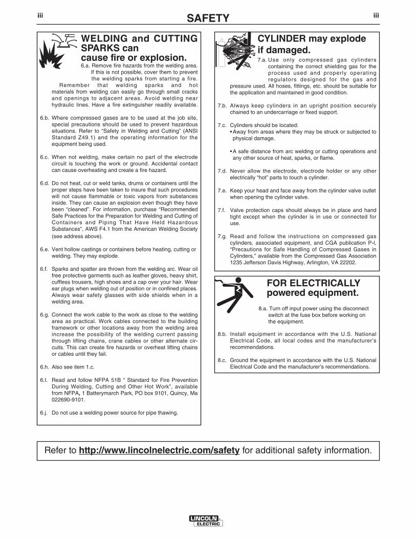
FOR ELECTRICALLYpowered equipment.
8.a. Turn off input power using the disconnectswitch at the fuse box before working onthe equipment.
8.b. Install equipment in accordance with the U.S. NationalElectrical Code, all local codes and the manufacturer’srecommendations.
8.c. Ground the equipment in accordance with the U.S. NationalElectrical Code and the manufacturer’s recommendations.
CYLINDER may explodeif damaged.7.a. Use only compressed gas cylinders
containing the correct shielding gas for theprocess used and properly operatingregulators designed for the gas and
pressure used. All hoses, fittings, etc. should be suitable forthe application and maintained in good condition.
7.b. Always keep cylinders in an upright position securelychained to an undercarriage or fixed support.
7.c. Cylinders should be located:• Away from areas where they may be struck or subjected tophysical damage.
• A safe distance from arc welding or cutting operations andany other source of heat, sparks, or flame.
7.d. Never allow the electrode, electrode holder or any otherelectrically “hot” parts to touch a cylinder.
7.e. Keep your head and face away from the cylinder valve outletwhen opening the cylinder valve.
7.f. Valve protection caps should always be in place and handtight except when the cylinder is in use or connected foruse.
7.g. Read and follow the instructions on compressed gascylinders, associated equipment, and CGA publication P-l,“Precautions for Safe Handling of Compressed Gases inCylinders,” available from the Compressed Gas Association1235 Jefferson Davis Highway, Arlington, VA 22202.
WELDING and CUTTINGSPARKS cancause fire or explosion.6.a. Remove fire hazards from the welding area.
If this is not possible, cover them to preventthe welding sparks from starting a fire.
Remember that welding sparks and hotmaterials from welding can easily go through small cracksand openings to adjacent areas. Avoid welding nearhydraulic lines. Have a fire extinguisher readily available.
6.b. Where compressed gases are to be used at the job site,special precautions should be used to prevent hazardoussituations. Refer to “Safety in Welding and Cutting” (ANSIStandard Z49.1) and the operating information for theequipment being used.
6.c. When not welding, make certain no part of the electrodecircuit is touching the work or ground. Accidental contactcan cause overheating and create a fire hazard.
6.d. Do not heat, cut or weld tanks, drums or containers until theproper steps have been taken to insure that such procedureswill not cause flammable or toxic vapors from substancesinside. They can cause an explosion even though they havebeen “cleaned”. For information, purchase “RecommendedSafe Practices for the Preparation for Welding and Cutting ofContainers and Piping That Have Held HazardousSubstances”, AWS F4.1 from the American Welding Society(see address above).
6.e. Vent hollow castings or containers before heating, cutting orwelding. They may explode.
6.f. Sparks and spatter are thrown from the welding arc. Wear oilfree protective garments such as leather gloves, heavy shirt,cuffless trousers, high shoes and a cap over your hair. Wearear plugs when welding out of position or in confined places.Always wear safety glasses with side shields when in awelding area.
6.g. Connect the work cable to the work as close to the weldingarea as practical. Work cables connected to the buildingframework or other locations away from the welding areaincrease the possibility of the welding current passingthrough lifting chains, crane cables or other alternate cir-cuits. This can create fire hazards or overheat lifting chainsor cables until they fail.
6.h. Also see item 1.c.
6.I. Read and follow NFPA 51B “ Standard for Fire PreventionDuring Welding, Cutting and Other Hot Work”, availablefrom NFPA, 1 Batterymarch Park, PO box 9101, Quincy, Ma022690-9101.
6.j. Do not use a welding power source for pipe thawing.
iiiSAFETYiii
Refer to http://www.lincolnelectric.com/safety for additional safety information.
PRÉCAUTIONS DE SÛRETÉPour votre propre protection lire et observer toutes les instructionset les précautions de sûreté specifiques qui parraissent dans cemanuel aussi bien que les précautions de sûreté générales suiv-antes:
Sûreté Pour Soudage A L’Arc1. Protegez-vous contre la secousse électrique:
a. Les circuits à l’électrode et à la piéce sont sous tensionquand la machine à souder est en marche. Eviter toujourstout contact entre les parties sous tension et la peau nueou les vétements mouillés. Porter des gants secs et sanstrous pour isoler les mains.
b. Faire trés attention de bien s’isoler de la masse quand onsoude dans des endroits humides, ou sur un planchermetallique ou des grilles metalliques, principalement dans les positions assis ou couché pour lesquelles une grandepartie du corps peut être en contact avec la masse.
c. Maintenir le porte-électrode, la pince de masse, le câblede soudage et la machine à souder en bon et sûr étatdefonctionnement.
d.Ne jamais plonger le porte-électrode dans l’eau pour lerefroidir.
e. Ne jamais toucher simultanément les parties sous tensiondes porte-électrodes connectés à deux machines à souderparce que la tension entre les deux pinces peut être letotal de la tension à vide des deux machines.
f. Si on utilise la machine à souder comme une source decourant pour soudage semi-automatique, ces precautionspour le porte-électrode s’applicuent aussi au pistolet desoudage.
2. Dans le cas de travail au dessus du niveau du sol, se protégercontre les chutes dans le cas ou on recoit un choc. Ne jamaisenrouler le câble-électrode autour de n’importe quelle partiedu corps.
3. Un coup d’arc peut être plus sévère qu’un coup de soliel,donc:
a. Utiliser un bon masque avec un verre filtrant appropriéainsi qu’un verre blanc afin de se protéger les yeux du ray-onnement de l’arc et des projections quand on soude ouquand on regarde l’arc.
b. Porter des vêtements convenables afin de protéger lapeau de soudeur et des aides contre le rayonnement del‘arc.
c. Protéger l’autre personnel travaillant à proximité ausoudage à l’aide d’écrans appropriés et non-inflammables.
4. Des gouttes de laitier en fusion sont émises de l’arc desoudage. Se protéger avec des vêtements de protection libresde l’huile, tels que les gants en cuir, chemise épaisse, pan-talons sans revers, et chaussures montantes.
5. Toujours porter des lunettes de sécurité dans la zone desoudage. Utiliser des lunettes avec écrans lateraux dans leszones où l’on pique le laitier.
6. Eloigner les matériaux inflammables ou les recouvrir afin deprévenir tout risque d’incendie dû aux étincelles.
7. Quand on ne soude pas, poser la pince à une endroit isolé dela masse. Un court-circuit accidental peut provoquer unéchauffement et un risque d’incendie.
8. S’assurer que la masse est connectée le plus prés possiblede la zone de travail qu’il est pratique de le faire. Si on placela masse sur la charpente de la construction ou d’autresendroits éloignés de la zone de travail, on augmente le risquede voir passer le courant de soudage par les chaines de lev-age, câbles de grue, ou autres circuits. Cela peut provoquerdes risques d’incendie ou d’echauffement des chaines et descâbles jusqu’à ce qu’ils se rompent.
9. Assurer une ventilation suffisante dans la zone de soudage.Ceci est particuliérement important pour le soudage de tôlesgalvanisées plombées, ou cadmiées ou tout autre métal quiproduit des fumeés toxiques.
10. Ne pas souder en présence de vapeurs de chlore provenantd’opérations de dégraissage, nettoyage ou pistolage. Lachaleur ou les rayons de l’arc peuvent réagir avec les vapeursdu solvant pour produire du phosgéne (gas fortement toxique)ou autres produits irritants.
11. Pour obtenir de plus amples renseignements sur la sûreté,voir le code “Code for safety in welding and cutting” CSAStandard W 117.2-1974.
PRÉCAUTIONS DE SÛRETÉ POURLES MACHINES À SOUDER ÀTRANSFORMATEUR ET ÀREDRESSEUR
1. Relier à la terre le chassis du poste conformement au code del’électricité et aux recommendations du fabricant. Le dispositifde montage ou la piece à souder doit être branché à unebonne mise à la terre.
2. Autant que possible, I’installation et l’entretien du poste seronteffectués par un électricien qualifié.
3. Avant de faires des travaux à l’interieur de poste, la debranch-er à l’interrupteur à la boite de fusibles.
4. Garder tous les couvercles et dispositifs de sûreté à leurplace.
ivSAFETYiv

vv
Thank You for selecting a QUALITY product by Lincoln Electric. We want youto take pride in operating this Lincoln Electric Company product••• as much pride as we have in bringing this product to you!
Read this Operators Manual completely before attempting to use this equipment. Save this manual and keep ithandy for quick reference. Pay particular attention to the safety instructions we have provided for your protection.The level of seriousness to be applied to each is explained below:
WARNINGThis statement appears where the information must be followed exactly to avoid serious personal injury or loss of life.
This statement appears where the information must be followed to avoid minor personal injury or damage to this equipment.
CAUTION
Please Examine Carton and Equipment For Damage ImmediatelyWhen this equipment is shipped, title passes to the purchaser upon receipt by the carrier. Consequently, Claimsfor material damaged in shipment must be made by the purchaser against the transportation company at thetime the shipment is received.
Please record your equipment identification information below for future reference. This information can befound on your machine nameplate.
Product _________________________________________________________________________________
Model Number ___________________________________________________________________________
Code Number or Date Code_________________________________________________________________
Serial Number____________________________________________________________________________
Date Purchased___________________________________________________________________________
Where Purchased_________________________________________________________________________
Whenever you request replacement parts or information on this equipment, always supply the information youhave recorded above. The code number is especially important when identifying the correct replacement parts.
CUSTOMER ASSISTANCE POLICYThe business of The Lincoln Electric Company is manufacturing and selling high quality welding equipment, consumables, and cutting equip-ment. Our challenge is to meet the needs of our customers and to exceed their expectations. On occasion, purchasers may ask LincolnElectric for advice or information about their use of our products. We respond to our customers based on the best information in our posses-sion at that time. Lincoln Electric is not in a position to warrant or guarantee such advice, and assumes no liability, with respect to such infor-mation or advice. We expressly disclaim any warranty of any kind, including any warranty of fitness for any customer’s particular purpose,with respect to such information or advice. As a matter of practical consideration, we also cannot assume any responsibility for updating orcorrecting any such information or advice once it has been given, nor does the provision of information or advice create, expand or alter anywarranty with respect to the sale of our products.
Lincoln Electric is a responsive manufacturer, but the selection and use of specific products sold by Lincoln Electric is solely within the controlof, and remains the sole responsibility of the customer. Many variables beyond the control of Lincoln Electric affect the results obtained inapplying these types of fabrication methods and service requirements.
Subject to Change – This information is accurate to the best of our knowledge at the time of printing. Please refer to www.lincolnelectric.comfor any updated information.
On-Line Product Registration- Register your machine with Lincoln Electric either via fax or over the Internet.• For faxing: Complete the form on the back of the warranty statement included in the literature packet
accompanying this machine and fax the form per the instructions printed on it.• For On-Line Registration: Go to our WEB SITE at www.lincolnelectric.com. Choose “Support” and then “Register
Your Product”. Please complete the form and submit your registration.

vivi TABLE OF CONTENTSPage
Installation.......................................................................................................................Section ATechnical Specifications.......................................................................................................A-1Safety Precautions. ..............................................................................................................A-2
Location ........................................................................................................................A-2Stacking ........................................................................................................................A-2Input Wiring ...................................................................................................................A-2Reconnect Procedures ..........................................................................................A-3, A-4Output Connections ......................................................................................................A-5
_______________________________________________________________________________Operation.........................................................................................................................Section B
Safety Precautions ...............................................................................................................B-1Product Description ..............................................................................................................B-1
To Set Polarity...............................................................................................................B-2Set-Up For Various Procedures....................................................................................B-2, B-3
________________________________________________________________________________Maintenance ....................................................................................................Section D
Safety Precautions ...................................................................................................D-1General Maintenance .........................................................................................D-1Overload Protection ...........................................................................................D-1
________________________________________________________________________Troubleshooting ..............................................................................................Section E
Safety Precautions.................................................................................................E-1How to Use Troubleshooting Guide.......................................................................E-1Troubleshooting Guide.............................................................................E-2 thru E-7
________________________________________________________________________Connection and Wiring Diagrams..................................................................Section F
________________________________________________________________________Parts List .........................................................................................P-146, P-720 Series
________________________________________________________________________
A-1INSTALLATION
IDEALARC® DC-1000
A-1
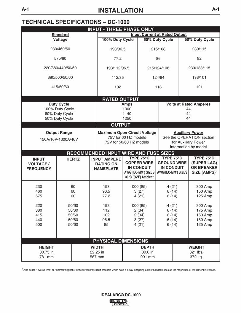
60% Duty Cycle
215/108
86
215/124/108
124/94
113
TECHNICAL SPECIFICATIONS – DC-1000
Volts at Rated Amperes444444
Auxiliary PowerSee the OPERATION section
for Auxiliary Power information by model
Amps100011401250
Maximum Open Circuit Voltage75V for 60 HZ models
72V for 50/60 HZ models
Duty Cycle100% Duty Cycle60% Duty Cycle50% Duty Cycle
Output Range
150A/16V-1300A/46V
INPUT - THREE PHASE ONLY
OUTPUT
1Also called “inverse time” or “thermal/magnetic” circuit breakers; circuit breakers which have a delay in tripping action that decreases as the magnitude of the current increases.
RECOMMENDED INPUT WIRE AND FUSE SIZES
StandardVoltage
230/460/60
575/60
220/380/440/50/60
380/500/50/60
415/50/60
100% Duty Cycle
193/96.5
77.2
193/112/96.5
112/85
102
50% Duty Cycle
230/115
92
230/133/115
133/101
121
Input Current at Rated Output
RATED OUTPUT
INPUTVOLTAGE /
FREQUENCY
230460575
220380415440500
TYPE 75°C(SUPER LAG)OR BREAKERSIZE (AMPS)1
300 Amp150 Amp125 Amp
300 Amp175 Amp150 Amp150 Amp125 Amp
TYPE 75°CGROUND WIRE
IN CONDUITAWG(IEC-MM2) SIZES
4 (21)6 (14)6 (14)
4 (21)6 (14)6 (14)6 (14)6 (14)
TYPE 75°CCOPPER WIRE
IN CONDUITAWG(IEC-MM2) SIZES30°C (86°F) Ambient
000 (85)3 (27)4 (21)
000 (85)2 (34)2 (34)3 (27)4 (21)
INPUT AMPERERATING ON
NAMEPLATE
19396.577.2
19311210296.585
HERTZ
606060
50/6050/6050/6050/6050/60
PHYSICAL DIMENSIONSHEIGHT30.75 in781 mm
WIDTH22.25 in567 mm
DEPTH39.0 in
991 mm
WEIGHT821 lbs.372 kg.
A-2INSTALLATION
IDEALARC® DC-1000
A-2
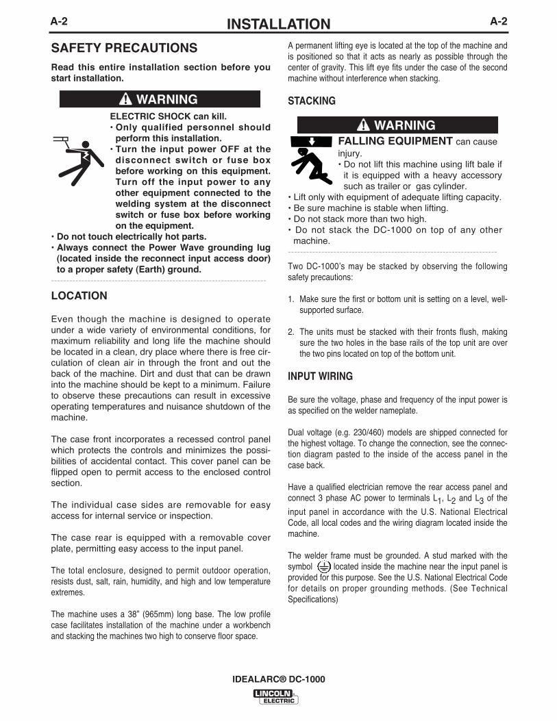
A permanent lifting eye is located at the top of the machine andis positioned so that it acts as nearly as possible through thecenter of gravity. This lift eye fits under the case of the secondmachine without interference when stacking.
STACKING
Two DC-1000ʼs may be stacked by observing the followingsafety precautions:
1. Make sure the first or bottom unit is setting on a level, well-supported surface.
2. The units must be stacked with their fronts flush, makingsure the two holes in the base rails of the top unit are overthe two pins located on top of the bottom unit.
INPUT WIRING
Be sure the voltage, phase and frequency of the input power isas specified on the welder nameplate.
Dual voltage (e.g. 230/460) models are shipped connected forthe highest voltage. To change the connection, see the connec-tion diagram pasted to the inside of the access panel in thecase back.
Have a qualified electrician remove the rear access panel andconnect 3 phase AC power to terminals L1, L2 and L3 of the
input panel in accordance with the U.S. National ElectricalCode, all local codes and the wiring diagram located inside themachine.
The welder frame must be grounded. A stud marked with thesymbol located inside the machine near the input panel isprovided for this purpose. See the U.S. National Electrical Codefor details on proper grounding methods. (See TechnicalSpecifications)
SAFETY PRECAUTIONSRead this entire installation section before youstart installation.
ELECTRIC SHOCK can kill.• Only qualified personnel should
perform this installation.• Turn the input power OFF at the
disconnect switch or fuse boxbefore working on this equipment.Turn off the input power to anyother equipment connected to thewelding system at the disconnectswitch or fuse box before workingon the equipment.
• Do not touch electrically hot parts.• Always connect the Power Wave grounding lug
(located inside the reconnect input access door)to a proper safety (Earth) ground.
-----------------------------------------------------------------------
FALLING EQUIPMENT can causeinjury.• Do not lift this machine using lift bale if
it is equipped with a heavy accessorysuch as trailer or gas cylinder.
• Lift only with equipment of adequate lifting capacity.• Be sure machine is stable when lifting.• Do not stack more than two high.• Do not stack the DC-1000 on top of any other
machine.---------------------------------------------------------------------
WARNING
LOCATION
Even though the machine is designed to operateunder a wide variety of environmental conditions, formaximum reliability and long life the machine shouldbe located in a clean, dry place where there is free cir-culation of clean air in through the front and out theback of the machine. Dirt and dust that can be drawninto the machine should be kept to a minimum. Failureto observe these precautions can result in excessiveoperating temperatures and nuisance shutdown of themachine.
The case front incorporates a recessed control panelwhich protects the controls and minimizes the possi-bilities of accidental contact. This cover panel can beflipped open to permit access to the enclosed controlsection.
The individual case sides are removable for easyaccess for internal service or inspection.
The case rear is equipped with a removable coverplate, permitting easy access to the input panel.
The total enclosure, designed to permit outdoor operation,resists dust, salt, rain, humidity, and high and low temperatureextremes.
The machine uses a 38” (965mm) long base. The low profilecase facilitates installation of the machine under a workbenchand stacking the machines two high to conserve floor space.
WARNING

A-3INSTALLATION
IDEALARC® DC-1000
A-3
RECONNECT PROCEDURE
Multiple voltage machines are shipped connected tothe highest input voltage listed on the machineʼs ratingplate. Before installing the machine, check that theReconnect Panel in the Input Box Assembly is con-nected for the proper voltage.
Failure to follow these instructions can causeimmediate failure of components within themachine.
When powering welder from a generator be sureto turn off welder first, before generator is shutdown, in order to prevent damage to the welder.
------------------------------------------------------------------------------------------------------
To reconnect a multiple voltage machine to a differentvoltage, remove input power and change the positionof the reconnect board on the Reconnect Panel.Follow The Input Connection Diagram located on theinside of Case Back Input Access Door. These con-nection diagrams for the following codes are listedbelow.
1. For Single and Dual Voltage except 380/500 seeFigure 1, (S17172).
2. For 220/380/460, see Figure 2, (M14358).
3. For 380/500, see Figure 3, (S17344).
4. For Voltages not listed, see the Input ConnectionDiagram pasted on the inside of the Case Back Input Access Door.
CAUTION
FIGURE 1

A-4INSTALLATION
IDEALARC® DC-1000
A-4
FIGURE 2
FIGURE 3

A-5INSTALLATION
IDEALARC® DC-1000
A-5
OUTPUT CONNECTIONS
Output Studs
The output leads are connected to the output termi-nals. The output terminals are located on the lowercase front and labeled “+” and “-”. There are 1000amp rated “+” terminals on the right side, one 500amp rated “+” terminal near the center and “-” termi-nals on the left side. They are fully recessed to mini-mize the possibility of accidental contact by an objector a person. Strain relief is provided by the oval holesin the base. The leads are run through these ovalholes before they are connected to the output termi-nals.
The 1000 amp output connections provide the fullrated output range of the machine. See Table1 forrecommended DC-1000 cable sizes for combinedlengths of electrode and work cables.
The 500 amp output connections provide enhancedlower current arc characteristics, especially for sub-merged arc and GMAW procedures below 450 amps.
Auxiliary Power
This machine supplies the 115 volt, AC power neededfor operating wire feeding equipment. The power isavailable from terminals #31 and #32 on the terminalstrip. An 8 amp slow blow fuse on the machine controlpanel protects the auxiliary power from excessiveoverloads. The circuit has a 1000 volt-ampere rating.
Control Cable Connection
Terminal strips with screw connections are locatedbehind the hinged door on the front of the powersource to make all the control cable connections foroperating wire feeding equipment. See the appropri-ate connection diagram for exact instructions coveringthe wire feeder being used.
With the DC-1000 turned off, the control cable fromthe automatic wire feeding equipment is connected tothe terminal strip. A strain relief box connector is pro-vided for access into the terminal strip section. Achassis grounding screw is also provided below theterminal strip marked with the symbol for connect-ing the wire feeding equipment grounding wire. Seethe appropriate connection diagram for the exactinstructions for the wire feeder being used. A sparehole is provided for an additional box connector ifrequired.
Connecting for Air Carbon Arc:
a. Turn off all power.b. Disconnect all wire feed unit control, electrode and
work leads.c. Connect a jumper from 2-4 on terminal strip.d. Place mode switch in the CV(I) position.
With the DC-1000 connected for air carbon arc weld-ing, the output terminals will be energized at all times.
Cable SizeParallel CablesCable Length
1/0 (53mm2)3
3
3
Lengths up to 150 ft. (46m)
2/0 (67mm2)150 ft.(46m) to 200 ft (61m)
3/0 (85mm2)200 ft.(61m) to 250 ft.(76m)
TABLE 1DC-1000 Cable Sizes for Combined Lengths of Copper Electrode and Work Cable
at 100% Duty CycleELECTRODE, WORK AND #21 LEAD

B-1OPERATION
IDEALARC® DC-1000
B-1
PRODUCT DESCRIPTION
The DC-1000 is an SCR-controlled three phase DCpower source. It is designed with a single rangepotentiometer control for submerged arc or open arcautomatic and semiautomatic welding. It can be usedfor air carbon arc cutting with carbon rods up to andincluding 5/8” (15.9mm) dia. The DC-1000 (belowcode 9500) is not recommended for stick welding orfor solid wire and gas in the short arc welding mode.With the addition of the 500 amp output stud to DC-1000 models above code 9500, GMAW procedurescan be performed. This connection provides theenhanced lower current arc characteristics requiredfor this type of welding.
The DC-1000 is provided with a three position modeswitch that selects CV Innershield®, CV SubmergedArc or CC (Variable Voltage) Submerged Arc.
The unit is designed to be used with the NA-5, NA-5Rand NA-3 automatics, the LT-56 and LT-7 tractors,and can also be used with the LN-7, LN-8 or LN-9semiautomatic wire feeders.
NOTE: All P.C. boards are protected by a moistureresistant coating. When the welder is operated, thiscoating will “bake off” of certain power resistors thatnormally operate at high temperatures emitting somesmoke and odor for a short time. These resistors andthe P.C. board beneath them may become blackened.This is a normal occurrence and does not damage thecomponent or affect the machine performance.
TO SET POLARITYTurn off the DC-1000 and connect the electrode cableto the “Positive” or “Negative” studs depending uponthe electrode polarity desired. Connect the work cableto the other stud. (See “Output Connections”).
Set the “Electrode Negative-Electrode Positive” switchto correspond to the polarity of the electrode cableconnection. This switch setting is necessary for properoperation of some Lincoln wire feeders and does notchange the welding polarity.
Starting the Machine - The push button power “on”switch at the extreme right side of the control panelenergizes and closes the three phase input contactorfrom a 115 volt auxiliary transformer. This in turn ener-gizes the main power transformer.
The red light below the stop-start button indicateswhen the input contactor is energized.
Output Control - The output control in the center ofthe control panel is a continuous control of themachine output. The control may be rotated from min.to max. while under load to adjust the machine output.
The machine is equipped with line voltage compensa-tion as a standard feature. This will hold the output rel-atively constant except at maximum output of themachine, through a fluctuation of +/- 10% of input linevoltage.
Output Control at DC-1000 or Output ControlRemote Switch
The toggle switch on the control panel labeled “OutputControl at DC-1000” / “Output Control Remote” givesthe operator the option of controlling the output at themachine control panel or at a remote station. Forremote control, the toggle switch is set in the “OutputControl Remote” position and controlled at the wirefeed unit control or by connecting a K775 control tothe appropriate terminals (as indicated on the connec-tion diagram) on the terminal strip at the front of themachine. For control at the machine control panel, thetoggle switch is set in the “Output Control at DC-1000”position.
OPERATING INSTRUCTIONS
ELECTRIC SHOCK can kill.• Do not touch electrically live parts orelectrode with skin or wet clothing.• Insulate yourself from work andground.• Always wear dry insulating gloves.
------------------------------------------------------------------------FUMES AND GASES can be danger-ous.• Keep your head out of fumes.• Use ventilation or exhaust to removefumes from breathing zone.
------------------------------------------------------------------------WELDING SPARKS can cause fire orexplosion.• Keep flammable material away.• Do not weld on closed containers.
------------------------------------------------------------------------ARC RAYS can burn eyes and skin.• Wear eye, ear and body protection.
------------------------------------------------------------
See additional warning information atfront of this operatorʼs manual.
-----------------------------------------------------------
WARNING

B-2INSTALLATION
IDEALARC® DC-1000
B-2
Remote Output Control - (Optional)
The K775 Remote Output Control consists of a controlbox with 28 ft. (8.4m) of four conductor cable. Thisconnects to terminals 75, 76, 77 on the terminal strip,and the case grounding screw so marked with thesymbol on the machine. These terminals aremade available by opening the terminal access coveron the left side of the case front. This control will givethe same control as the output control on themachine.
Mode Switch
The toggle switch labeled C (I) Innershield, CV(S)Submerged Arc, CC (or Variable Voltage) is used toselect the proper welder characteristics for theprocess being used. The CC (or Variable Voltage)mode is primarily available for use with older wirefeeding equipment such as the LAF-3, LT-34 and soforth. Use of this type of older equipment requires theaddition of an NL Option Kit.
SET-UP FOR VARIOUS PROCEDURES
1. Selection of mode switch position - There areseveral general rules to follow in the selection ofthe mode switch position.
a. Use the CV(I) mode for all FCAW and GMAWprocesses. The CV(I) mode is also used forair carbon arc using carbon rods up to andincluding 5/8” (15.9mm) dia.
Welding with NR®-151, 202, 203 and otherelectrodes below 20 volts, is not recommend-ed.
b. Use the CV(S) mode for all submerged arcwelding. This applies to both low and hightravel speeds.
c. The CC (Variable Voltage) mode is availablefor high current large puddle submerged arcprocedures that cannot be done as well withthe constant voltage mode. CC mode shouldbe used for 3/16” (4.8mm) diameter electrodeand above where high current surges causemachine shutdown when starting. This occursprimarily when the slag ball is not cut from theelectrode prior to starting. (Also requires awire feeder that has a constant current mode- i.e. NA-3S).
NOTE: Some processes and procedures may be bet-ter with the mode switch in the other CV position. Ifthe mode switch position initially selected is not pro-ducing the desired results, then place the mode switchin the other CV position and make a test weld. Thenuse the CV mode switch position that gives thedesired results.
2. NA-3 - The NA-3 should be set for the mode beingused on the power source. If using either of theCV modes, the NA-3 CC board switch should beset for CV. If the power source is used in the CCmode, then the NA-3 CC board mode switchshould be placed in the CC position.
All the NA-3ʼs when used with the DC-1000 are capa-ble of cold starting with the constant current boardmode switch in CC. Cold starting permits the wire tobe inched down to the work, automatically stop, andautomatically energize the flux hopper valve. All NA-3ʼs made after September, 1976 are capable of coldstarting on either CV or CC settings of the constantcurrent board.
On the NA-3, set the open circuit voltage control to thesame dial setting as the arc voltage control. If the pro-cedure has not yet been established, a good startingpoint is to set the OCV to #6.
Run a test weld, setting the proper current, voltageand travel speed. Once the proper welding procedureis established and if the start is poor - wire blast off,stub, etc. - adjust the NA-3 OCV and inch speed con-trols for optimum starting. In general, a low inch speedand an OCV dial setting identical to the voltage dialsetting will provide the best starting.
To further optimize starting, adjust the OCV by makingrepeated starts and observing the NA-3 voltmeteraction. With proper adjustment of the OCV control, thevoltmeter needle will swing smoothly up to the desiredarc voltage and thus provide repeatable starts.
If the voltmeter swings above the set voltage and thenback to the desired welding voltage, the OCV settingis too high. This usually results in a bad start wherethe wire tends to “blast off”.
If the voltmeter needle hesitates before coming up tothe desired voltage, the OCV is set too low. This willcause the electrode to stub.

B-3INSTALLATION
IDEALARC® DC-1000
B-3
3. NA-5 - Set the DC-1000 mode switch to theprocess being used - CV(I) Innershield or CV(S)Sub Arc. Set the DC-1000 machine/remote switchin the remote position. Set the OCV control fourvolts higher than the welding voltage and the inchspeed at 1/2 the welding wire feed speed for theinitial test weld. Adjust the OCV and inch speed asrequired for optimum starting. Refer to the NA-5instruction manual for data regarding the setup ofcontrols and modes on the NA-5.
4. LN-8 - Set the LN-8 mode switch (located on theCC board) to the CV position. Set the DC-1000mode switch on CV(I) Innershield or CV(S) SubArc according to the process being used.
5. LN-7, LN-9 and other constant wire feed units -Set the DC-1000 mode switch on CV(I) Innershieldor CV(S) Sub Arc according to the process beingused. If using an LN-9, refer to the LN-9 instructionmanual for further instructions on its use. If usingan LN-7, it will be necessary to use either a K775Remote Control or operate the DC-1000 with themachine/remote switch in the machine position.
NL Option Kit (Not Required with NA-3, NA-5, LT-7or LT-56).
The K783 NL Option Kit (for field installation) isdesigned to permit use of the obsolete NA-2, LAF-3,LT-3 and LT-3 section of the LT-34 tractor. It providesthe necessary DC control power for the operation ofthe equipment and the necessary circuitry for properinching, cold starting and arc striking. In using the NLOption Kit, a K775 remote field control is required andis included as part of the kit. Installation instructionsare included with the NL Option Kit.
D-1MAINTENANCED-1
The control board is designed with adequate protec-tion so that no damage will occur if the remote controlleads are shorted together or are grounded to thecase. The machine will automatically shut down ifsuch faults do occur.
An 8-amp fuse located on the machine control panelprotects the 115 volt auxiliary AC circuit (#31 and #32)from overload. If replacing, use the same type andsize fuse.
IDEALARC® DC-1000
SAFETY PRECAUTIONS
ELECTRIC SHOCK can kill.• Only qualified personnel should
perform this installation.• Turn the input power OFF at the
disconnect switch or fuse box beforeworking on this equipment.
• Do not touch electrically hot parts.------------------------------------------------------------------------GENERAL MAINTENANCE
1. The fan motors have sealed bearings whichrequire no service.
2. In extremely dusty locations, dirt may clog the airchannels causing the welder to run hot. Blow outthe welder with low pressure air at regular inter-vals as required to eliminate excessive dirt anddust buildup on internal parts.
OVERLOAD PROTECTION
The power source is thermostatically protected withtwo proximity thermostats against overload or insuffi-cient cooling. One thermostat is located on the trans-former secondary Negative Output Lead, and theother thermostat is located on the choke coil. Thethermostats are connected in series in the machinecontrol circuit so that if an excessive overload isapplied to the machine, or the machine should receiveinsufficient cooling on either the main transformer,SCR bridge assembly or choke, the input contactorwould open and remain open until the machine cools.It can then be manually restarted by operating thestart push button.
The power source is also protected against heavyoverloads on the SCR bridge assembly through anelectronic protection circuit. This circuit senses anoverload on the power source and opens the inputcontactor should the overload remain for a predeter-mined time. The predetermined time varies with theamount of overload; the greater the overload, theshorter the time. The input contactor will remain openuntil the power source is manually started with thestart push button.
WARNING

E-1TROUBLESHOOTINGE-1
IDEALARC® DC-1000
If for any reason you do not understand the test procedures or are unable to perform the tests/repairs safely, contact yourLocal Lincoln Authorized Field Service Facility for technical troubleshooting assistance before you proceed.
CAUTION
This Troubleshooting Guide is provided to help youlocate and repair possible machine malfunctions.Simply follow the three-step procedure listed below.
Step 1. LOCATE PROBLEM (SYMPTOM).Look under the column labeled “PROBLEM (SYMP-TOMS)”. This column describes possible symptomsthat the machine may exhibit. Find the listing thatbest describes the symptom that the machine isexhibiting.
Step 2. POSSIBLE CAUSE.The second column labeled “POSSIBLE CAUSE” liststhe obvious external possibilities that may contributeto the machine symptom.
Step 3. RECOMMENDED COURSE OF ACTIONThis column provides a course of action for thePossible Cause, generally it states to contact yourlocal Lincoln Authorized Field Service Facility.
If you do not understand or are unable to perform theRecommended Course of Action safely, contact yourlocal Lincoln Authorized Field Service Facility.
HOW TO USE TROUBLESHOOTING GUIDE
Service and Repair should only be performed by Lincoln Electric Factory Trained Personnel.Unauthorized repairs performed on this equipment may result in danger to the technician andmachine operator and will invalidate your factory warranty. For your safety and to avoid ElectricalShock, please observe all safety notes and precautions detailed throughout this manual.
__________________________________________________________________________
WARNING

E-2TROUBLESHOOTINGE-2
IDEALARC® DC-1000
Observe all Safety Guidelines detailed throughout this manual
If for any reason you do not understand the test procedures or are unable to perform the tests/repairs safely, contact yourLocal Lincoln Authorized Field Service Facility for technical troubleshooting assistance before you proceed.
CAUTION
PROBLEMS(SYMPTOMS)
POSSIBLE CAUSE
RECOMMENDEDCOURSE OF ACTION
Input contactor (1CR) chatters.
Machine input contactor does not oper-ate.
Input contactor pulls in when start buttonis pressed, but immediately drops out.
Machine input contactor operates but nooutput when trying to weld.
1. Faulty input contactor (1CR).2. Low line voltage.3. Faulty 2CR relay.
1. Supply line fuse blown.
2. Contactor power circuit dead.
3. Broken power lead.4. Wrong input voltage.5. Secondary or choke thermostat open.
6. Open input contactor coil.7. Faulty stop/start push button switch.8. Faulty 2CR relay.9. Defective control board.
1. Defective start/stop push button.2. Defective 1CR interlock.3. Ground fault between control termi-
nals 73, 74, 75, 76 or 77 and nega-tive output terminal.
4. Short on output terminals with 2-4jumpered.
5. Defective control board.
1. Electrode or work lead loose or bro-ken.
2. Open main transformer (T1) primaryor secondary circuit.
3. Output pilot relay 4CR not operatingor faulty.
4. Firing circuit P.C. board not connect-ed or is faulty.
5. If using 500 amp stud, choke circuitmay be open.
1. Repair or replace.2. Check input power.3. Repair relay.
1. Replace if blown - look for reasonfirst.
2. Check pilot transformer T2 and asso-ciated leads.
3. Check input voltage at contactor.4. Check voltage against instructions.5. Check for overheating; make sure fan
is operating and there is no obstruc-tion to free air flow. Replace faultythermostat.
6. Replace coil.7. Replace switch.8. Replace relay.9. Replace control board. See P.C.
board troubleshooting guide.
1. Check and replace if necessary.2. Repair or replace.3. Check 73, 74, 75, 76 or 77 for ground
to negative output circuit.
4. Remove short.
5. Replace control board. See P.C.board troubleshooting guide.
1. Repair connection.
2. Repair.
3. Check relay pull-in by connecting ajumper across terminals 2 and 4 onDC-1000 terminal strip. Replace iffaulty.
4. All nine light emitting diodes (LED1thru LED9) must be lit. See P.C.board troubleshooting guide.
5. Repair.

E-3TROUBLESHOOTINGE-3
IDEALARC® DC-1000
Observe all Safety Guidelines detailed throughout this manual
If for any reason you do not understand the test procedures or are unable to perform the tests/repairs safely, contact yourLocal Lincoln Authorized Field Service Facility for technical troubleshooting assistance before you proceed.
CAUTION
PROBLEMS(SYMPTOMS)
POSSIBLE CAUSE
RECOMMENDEDCOURSE OF ACTION
Machine has maximum output butnot control.
Machine has minimum output and nocontrol.
Machine does not have maximumoutput.
Variable or sluggish welding arc.
Machine has output but trips offimmediately when wire feed unitstart button is pressed.
Machine will not shut off.
Output control not functioning on themachine(1).
1. Output control switch (SW3) in wrongposition.
2. Output control switch faulty.3. Open in feedback circuitry.
4. Faulty control or firing circuit P.C.boards.
5. Output control potentiometer circuitopen (Lead 75).
1. Terminals 73, 74, 75, 76 or 77grounded to positive output.
1. One input fuse blown.
2. One phase of main transformer open.3. Faulty control or firing circuit P.C.
boards.
4. Output control potentiometer defec-tive.
5. Output control potentiometer leadsopen - 76, 77, 226, 236, 237, 238.
1. Machine has either an internal orexternal short circuit on the output.
2. Faulty control P.C. board.
3. Terminals 73, 74, 75, 76, 77 ground-ed to negative output terminal.
1. Poor work or electrode connection.2. Welding leads too small.3. Welding current or voltage too low.
4. Defective main SCR bridge.
1. Input contactor contacts frozen.2. Faulty 2CR relay.
1. Check position of switch.
2. Check switch and replace if faulty.3. Check wiring and control and firing
circuit P.C. board wiring harnessplugs.
4. All light emitting diodes must be lit,except LED4 on the control/faultboard. See P.C. board troubleshoot-ing guide.
5. Check and replace potentiometer iffaulty. Check wiring of Lead #75.
1. Check 73, 74, 75, 76 or 77 for groundto positive output circuit.
1. Check and replace if blown afterchecking for reason for blown fuse.
2. Check for open and repair.3. All light emitting diodes must be lit on
both P.C. boards, except LED4 oncontrol/fault board. See P.C. boardtroubleshooting guide.
4. Check and replace if faulty.
5. Repair.
1. Check internally and externally forany shorts and remove or repair.
2. Replace control board. See P.C.board troubleshooting guide.
3. Check for grounded 73, 74, 75, 76,77.
1. Check and clean all connections.2. Check table in instruction manual.3. Check procedures for recommended
settings.4. Check and replace if defective.
1. Check and replace if necessary.2. Check and replace if necessary.
(1) If connected to an LN-9 or NA-5, disconnect leads 73, 74, 75 before troubleshooting.
E-4TROUBLESHOOTINGE-4
IDEALARC® DC-1000
Observe all Safety Guidelines detailed throughout this manual
If for any reason you do not understand the test procedures or are unable to perform the tests/repairs safely, contact yourLocal Lincoln Authorized Field Service Facility for technical troubleshooting assistance before you proceed.
CAUTION
PROBLEMS(SYMPTOMS)
POSSIBLE CAUSE
RECOMMENDEDCOURSE OF ACTION
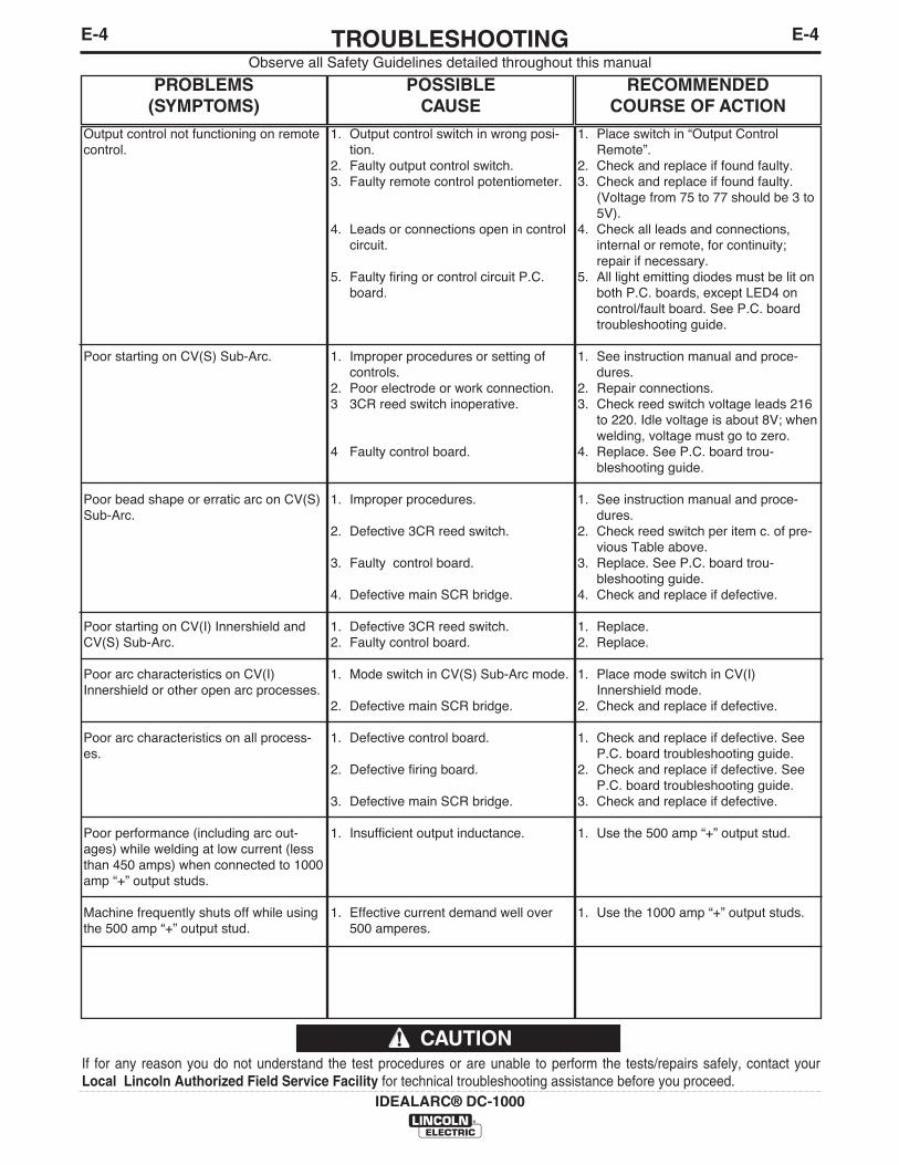
Output control not functioning on remotecontrol.
Poor starting on CV(S) Sub-Arc.
Poor bead shape or erratic arc on CV(S)Sub-Arc.
Poor starting on CV(I) Innershield andCV(S) Sub-Arc.
Poor arc characteristics on CV(I)Innershield or other open arc processes.
Poor arc characteristics on all process-es.
Poor performance (including arc out-ages) while welding at low current (lessthan 450 amps) when connected to 1000amp “+” output studs.
Machine frequently shuts off while usingthe 500 amp “+” output stud.
1. Output control switch in wrong posi-tion.
2. Faulty output control switch.3. Faulty remote control potentiometer.
4. Leads or connections open in controlcircuit.
5. Faulty firing or control circuit P.C.board.
1. Improper procedures or setting ofcontrols.
2. Poor electrode or work connection.3 3CR reed switch inoperative.
4 Faulty control board.
1. Improper procedures.
2. Defective 3CR reed switch.
3. Faulty control board.
4. Defective main SCR bridge.
1. Defective 3CR reed switch.2. Faulty control board.
1. Mode switch in CV(S) Sub-Arc mode.
2. Defective main SCR bridge.
1. Defective control board.
2. Defective firing board.
3. Defective main SCR bridge.
1. Insufficient output inductance.
1. Effective current demand well over500 amperes.
1. Place switch in “Output ControlRemote”.
2. Check and replace if found faulty.3. Check and replace if found faulty.
(Voltage from 75 to 77 should be 3 to5V).
4. Check all leads and connections,internal or remote, for continuity;repair if necessary.
5. All light emitting diodes must be lit onboth P.C. boards, except LED4 oncontrol/fault board. See P.C. boardtroubleshooting guide.
1. See instruction manual and proce-dures.
2. Repair connections.3. Check reed switch voltage leads 216
to 220. Idle voltage is about 8V; whenwelding, voltage must go to zero.
4. Replace. See P.C. board trou-bleshooting guide.
1. See instruction manual and proce-dures.
2. Check reed switch per item c. of pre-vious Table above.
3. Replace. See P.C. board trou-bleshooting guide.
4. Check and replace if defective.
1. Replace.2. Replace.
1. Place mode switch in CV(I)Innershield mode.
2. Check and replace if defective.
1. Check and replace if defective. SeeP.C. board troubleshooting guide.
2. Check and replace if defective. SeeP.C. board troubleshooting guide.
3. Check and replace if defective.
1. Use the 500 amp “+” output stud.
1. Use the 1000 amp “+” output studs.

E-5TROUBLESHOOTINGE-5
IDEALARC® DC-1000
Observe all Safety Guidelines detailed throughout this manual
If for any reason you do not understand the test procedures or are unable to perform the tests/repairs safely, contact yourLocal Lincoln Authorized Field Service Facility for technical troubleshooting assistance before you proceed.
CAUTION
P.C. BOARD TROUBLESHOOTING GUIDE
ELECTRIC SHOCK can kill.• Have an electrician install and servicethis equipment.• Turn the input power off at the fusebox before working on equipment.
• Do not touch electrically hot parts.---------------------------------------------------------------------
WARNING
Machine settings for P.C. board troubleshooting.Disconnect all leads to the wire feeder and jumper ter-minals #2 and #4 on DC-1000. Output Control at DC-1000. Mode switch in the CV(I) position.
CONTROL/FAULT PROTECTION P.C.BOARD
1. LED1 indicates AC input voltage is present at pins255-256. If not lit, check the voltage across thesecondary winding of the control transformer, T2.The voltage should be approximately 115 volts. Ifnot, the problem is in the power supply and not theP.C. board.
2. LED2 indicates welder output voltage is being sup-plied to the control circuit. If not lit, check to makecertain lead 222 from pin 2 of the 15-pin controlcircuit P.C. board connector is connected to thepower source negative output lead and is not bro-ken.
3. LED3 indicates power is being applied to fault pro-tection pilot relay 2CR to turn on the input contac-tor.
4. LED4 indicates when overcurrent protection circuitis being activated.
5. LED5 indicates a control signal is being suppliedto the firing circuit. As the output control is varied,LED5 should change brilliancy from bright at lowoutput to dim at high output.
FIRING CIRCUIT P.C. BOARD
All nine light emitting diodes must be lit when thepower source is turned on and the wire feed arc startbutton is pressed or a jumper is connected between 2and 4.
1. Lights 7, 8, and 9 indicate AC power being sup-plied to the P.C. boards from T1 auxiliary winding.If a light is not lit, turn the machine off and unplugP5 from J5 on the firing P.C. board. Turn themachine on and check the following voltages:
• If approximately 75 VAC is present, turn themachine off, plug P5 back into firing board. Turnthe machine back on and check to see if the lightor lights are on. If the light or lights are not onreplace the firing P.C. board.
• If the 75 VAC was not present, then check thewiring.
2. Lights 1 through 6 indicate gate signals are beingsupplied to the main power SCRʼs 1 through 6respectively. If light 5 on the control circuit andlights 7 through 9 on the firing circuit are lit andlights 1 through 6 are not lit, check lead 231between the firing circuit and the control circuitthat it is not broken and is connected to eachMolex connector. If the lead shows continuity andlights 1 through 6 are not lit, replace the firing cir-cuit P.C. board. If any one of the lights 1 through 6is not lit and lights 7 through 9 are lit, replace thefiring circuit P.C. board.
Light That Check AC Voltage Voltage Should Was Off Between Pins of Be Approx.
Plug P5
7 P5 Pins 2 & 4 75 VAC(Wires 203, 204)
8 P5 Pins 7 & 3 75 VAC(Wires 205, 206)
9 P5 Pins 9 & 8 75 VAC(Wires 207, 208)

E-6TROUBLESHOOTINGE-6
IDEALARC® DC-1000
Observe all Safety Guidelines detailed throughout this manual
If for any reason you do not understand the test procedures or are unable to perform the tests/repairs safely, contact yourLocal Lincoln Authorized Field Service Facility for technical troubleshooting assistance before you proceed.
CAUTION
PROCEDURE FOR REPLACING P.C.BOARDS
When P.C. board is to be replaced, the following pro-cedure must be followed:
1. Visually inspect P.C. board in question. Are any ofthe components damaged? Is a conductor on theback side of the board damaged? All P.C. boardsare protected by a moisture resistant coating.When the welder is operated, this coating will“bake off” of certain power resistors that normallyoperate at high temperatures emitting somesmoke and odor for a short time. These resistorsand the P.C. board beneath them may becomeblackened. This is a normal occurrence and doesnot damage the component or affect the machineperformance.
a. If there is no damage to the P.C. board, inserta new one and see if this remedies the prob-lem. If the problem is remedied, replace theold P.C. board and see if the problem stillexists with the old P.C. board.
1) If the problem is no longer present with theold board, check the P.C. board harnessplug and P.C. board plug for corrosion,contamination, or oversize.
2) Check leads in the harness for loose con-nections.
b. If there is damage to the P.C. board, refer tothe Troubleshooting Guide
E-7TROUBLESHOOTINGE-7
IDEALARC® DC-1000
If for any reason you do not understand the test procedures or are unable to perform the tests/repairs safely, contact yourLocal Lincoln Authorized Field Service Facility for technical troubleshooting assistance before you proceed.
CAUTION
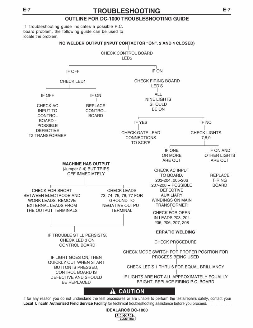
MACHINE HAS OUTPUT(Jumper 2-4) BUT TRIPS
OFF IMMEDIATELY
CHECK FOR SHORT CHECK LEADSBETWEEN ELECTRODE AND 73, 74, 75, 76, 77 FOR
WORK LEADS, REMOVE GROUND TOEXTERNAL LEADS FROM NEGATIVE OUTPUTTHE OUTPUT TERMINALS TERMINAL
IF TROUBLE STILL PERSISTS,CHECK LED 3 ONCONTROL BOARD
IF LIGHT GOES ON, THENQUICKLY OUT WHEN START
BUTTON IS PRESSED,CONTROL BOARD IS
DEFECTIVE AND SHOULDBE REPLACED
ERRATIC WELDING
CHECK PROCEDURE
CHECK MODE SWITCH FOR PROPER POSITION FORPROCESS BEING USED
CHECK LEDʼS 1 THRU 6 FOR EQUAL BRILLIANCY
IF LIGHTS ARE NOT ALL APPROXIMATELY EQUALLYBRIGHT, REPLACE FIRING P.C. BOARD
OUTLINE FOR DC-1000 TROUBLESHOOTING GUIDE
If troubleshooting guide indicates a possible P.C.board problem, the following guide can be used tolocate the problem.
NO WELDER OUTPUT (INPUT CONTACTOR “ON”. 2 AND 4 CLOSED)
CHECK CONTROL BOARDLED5
IF OFF
CHECK LED1
IF ON
CHECK FIRING BOARDLEDʼS
ALLNINE LIGHTS
SHOULDBE ON
IF OFF IF ON
CHECK AC REPLACEINPUT TO CONTROLCONTROL BOARDBOARD -
POSSIBLEDEFECTIVE
T2 TRANSFORMER
IF YES IF NO
CHECK GATE LEAD CHECK LIGHTSCONNECTIONS 7,8,9
TO SCRʼS
IF ONE IF ON ANDOR MORE OTHER LIGHTSARE OUT ARE OUT
CHECK AC INPUTTO BOARD, REPLACE
203-204, 205-206 FIRING207-208 -- POSSIBLE BOARD
DEFECTIVEAUXILIARY
WINDINGS ON MAINTRANSFORMER
CHECK FOR OPENIN LEADS 203, 204205, 206, 207, 208
F-1DIAGRAMSF-1
IDEALARC® DC-1000
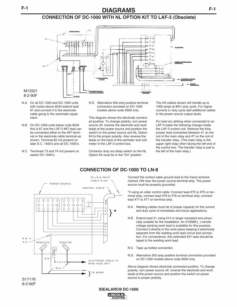
CONNECTION OF DC-1000 WITH NL OPTION KIT TO LAF-3 (Obsolete)
N.A. On all DC-1000 and DC-1500 unitswith codes above 8234 extend lead67 and connect it to the electrodecable going to the automatic equip-ment.
N.B. On DC-1500 units below code 8234this is 67 and the LAF-3 #67 lead canbe connected either to the #67 termi-nal or the electrode cable terminal asshown. Terminal 82 not present onlater D.C. 1500ʼs and all DC-1000ʼs.
N.C. Terminals 73 and 74 not present onearlier DC-1500ʼs.
N.D. Alternative 500 amp positive terminalconnection provided on DC-1000models above code 9500 only.
This diagram shows the electrode connect-ed positive. To change polarity, turn powersource off, reverse the electrode and workleads at the power source and position theswitch on the power source and NL OptionKit to the proper polarity. Also reverse theleads on the back of the ammeter and volt-meter in the LAF-3 control box.
Contactor drop out delay switch on the NLOption Kit must be in the “On” position.
The 4/0 cables shown will handle up to1000 amps at 80% duty cycle. For highercurrents or duty cycle add additional cablesto the power source output studs.
For best arc striking when connected to anLAF-3 make the following change insidethe LAF-3 control unit. Remove the bluejumper lead connected between #1 on thecoil of the main relay and #7 on the coil ofthe transfer relay. (The main relay is theupper right relay when facing the left end ofthe control box. The transfer relay is just tothe left of the main relay.)
S171768-2-90F
CONNECTION OF DC-1000 TO LN-8
Connect the control cable ground lead to the frame terminalmarked near the power source terminal strip. The powersource must be properly grounded.
*If using an older control cable: Connect lead #75 to #75 on ter-minal strip, connect lead #76 to #76 on terminal strip, connectlead #77 to #77 on terminal strip.
N.A. Welding cables must be of proper capacity for the currentand duty cycle of immediate and future applications.
N.B. Extend lead 21 using #14 or larger insulated wire physi-cally suitable for the installation. An S16586-[ ] remotevoltage sensing work lead is available for this purpose.Connect it directly to the work piece keeping it electricallyseparate from the welding work lead circuit and connec-tion. For convenience, this extended #21 lead should betaped to the welding work lead.
N.C. Tape up bolted connection.
N.D. Alternative 500 amp positive terminal connection providedon DC-1000 models above code 9500 only.
Above diagram shows electrode connected positive. To changepolarity, turn power source off, reverse the electrode and workleads at the power source and position the switch on powersource to proper polarity.
82 21 4 2 31 32
�
77767574
�
73
��
67 21 4 2 31 32 75 76 77
N.C.POWER SOURCE
N.B.
N.A. NEGATIVE POSITIVE
N.D.
TO WORK
ELECTRODE CABLE TO�AUTOMATIC EQUIPMENT
35 VOLT CONTROL� EXCITER
21 1
6 4 2 1 10 21 32 31 18 45 29 5
TAPE UP LEADS� NOT USED
K775 REMOTE CONTROL�MOUNTED AT LAF-3
TO LAF-3�CONTROL BOX
CONNECT THE RED LEAD TO�TERMINAL 22
75
76
77
75
76
77
GND
22
31
32
21
10
1
2
4
NL OPTION
106
E D
F C
2 1 4 2 3 1 3 2 7 3 7 4 7 5 7 6 7 7
4
GN
D
P O W E R S O U R C E
N E G A T I V E P O S I T I V E
2 1
N . A .
E L E C T R O D E C A B L E T O
T O W O R K}
T O L N - 8 I N P U T
C A B L E P L U G
C O N T R O L C A B L E
3 23 1
2
C
B
A } *
W I R E F E E D U N I T
N . D .
N . B . &
N . C .
M133218-2-90F
F-2DIAGRAMSF-2
IDEALARC® DC-1000
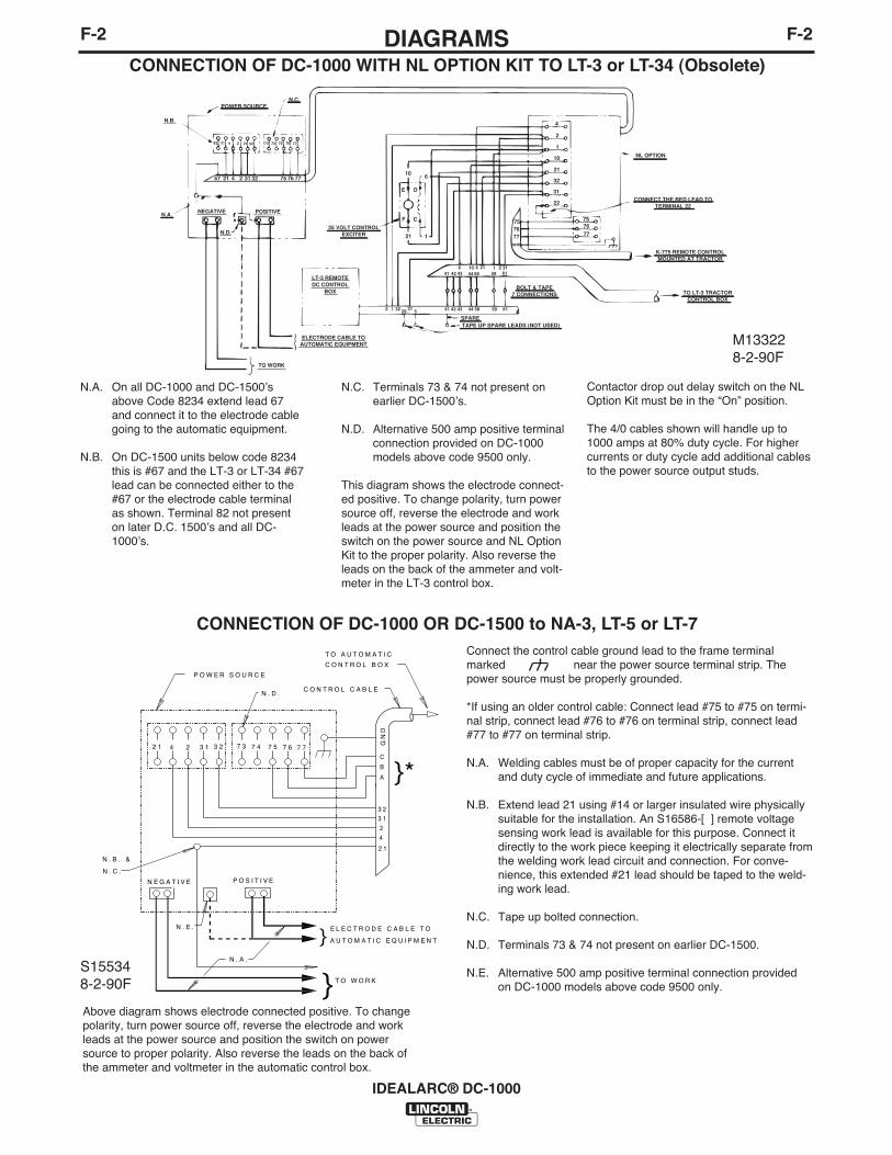
CONNECTION OF DC-1000 WITH NL OPTION KIT TO LT-3 or LT-34 (Obsolete)
N.A. On all DC-1000 and DC-1500ʼsabove Code 8234 extend lead 67and connect it to the electrode cablegoing to the automatic equipment.
N.B. On DC-1500 units below code 8234this is #67 and the LT-3 or LT-34 #67lead can be connected either to the#67 or the electrode cable terminalas shown. Terminal 82 not presenton later D.C. 1500ʼs and all DC-1000ʼs.
N.C. Terminals 73 & 74 not present onearlier DC-1500ʼs.
N.D. Alternative 500 amp positive terminalconnection provided on DC-1000models above code 9500 only.
This diagram shows the electrode connect-ed positive. To change polarity, turn powersource off, reverse the electrode and workleads at the power source and position theswitch on the power source and NL OptionKit to the proper polarity. Also reverse theleads on the back of the ammeter and volt-meter in the LT-3 control box.
Contactor drop out delay switch on the NLOption Kit must be in the “On” position.
The 4/0 cables shown will handle up to1000 amps at 80% duty cycle. For highercurrents or duty cycle add additional cablesto the power source output studs.
CONNECTION OF DC-1000 OR DC-1500 to NA-3, LT-5 or LT-7Connect the control cable ground lead to the frame terminalmarked near the power source terminal strip. Thepower source must be properly grounded.
*If using an older control cable: Connect lead #75 to #75 on termi-nal strip, connect lead #76 to #76 on terminal strip, connect lead#77 to #77 on terminal strip.
N.A. Welding cables must be of proper capacity for the currentand duty cycle of immediate and future applications.
N.B. Extend lead 21 using #14 or larger insulated wire physicallysuitable for the installation. An S16586-[ ] remote voltagesensing work lead is available for this purpose. Connect itdirectly to the work piece keeping it electrically separate fromthe welding work lead circuit and connection. For conve-nience, this extended #21 lead should be taped to the weld-ing work lead.
N.C. Tape up bolted connection.
N.D. Terminals 73 & 74 not present on earlier DC-1500.
N.E. Alternative 500 amp positive terminal connection providedon DC-1000 models above code 9500 only.
Above diagram shows electrode connected positive. To changepolarity, turn power source off, reverse the electrode and workleads at the power source and position the switch on powersource to proper polarity. Also reverse the leads on the back ofthe ammeter and voltmeter in the automatic control box.
TO WORK
LT-3 REMOTEDC CONTROL
BOX
ELECTRODE CABLE TOAUTOMATIC EQUIPMENT
N.D.
NEGATIVE POSITIVEN.A.
N.B.
POWER SOURCEN.C.
73 74 75 76 7782 21 4 2 31 32
67 21 4 2 31 32 75 76 77
35 VOLT CONTROLEXCITER 21 1
CF
E D
10 6
757677
GND
757677
1
4
2
10
21
32
31
22
BOLT & TAPE7 CONNECTIONS
41 42 43 44 58 59 616 10 4 21 1 2 31
SPARETAPE UP SPARE LEADS (NOT USED)
2 1 32 3129 5 41 42 43 44 58 59 61
NL OPTION
CONNECT THE RED LEAD TOTERMINAL 22
K-775 REMOTE CONTROLMOUNTED AT TRACTOR
TO LT-3 TRACTORCONTROL BOX
2 1 4 2 3 1 3 2 7 3 7 4 7 5 7 6 7 7
4
GN
D
P O W E R S O U R C E
N E G A T I V E P O S I T I V E
2 1
N . A .
E L E C T R O D E C A B L E T O
T O W O R K
}
C O N T R O L C A B L E
3 23 1
2
C
B
A }*
N . B . &
N . C .
T O A U T O M A T I C
C O N T R O L B O X
N . D .
N . E .
A U T O M A T I C E Q U I P M E N T
}
M133228-2-90F
S155348-2-90F

F-3DIAGRAMSF-3
IDEALARC® DC-1000
CONNECTION OF DC-1000 to NA-5N.A. Welding cables must be of proper capacity for the cur-
rent and duty cycle of immediate and future applica-tions.
N.B. Extend lead 21 using #14 or larger insulated wire phys-ically suitable for the installation. An S16586-[ ] remotevoltage sensing work lead is available for this purpose.Connect it directly to the work piece keeping it separatefrom the welding work cable connection to work piece.For convenience, this extended #21 lead should betaped along the welding work cable.
N.C. Tape up bolted connection.
N.D. Connect the NA-5 control cable ground lead to theframe terminal marked near the power source ter-minal strip. The power source must be properly ground-ed.
N.E. If using an older automatic control cable with leads 75,76, 77: Connect lead 75 to #75 on terminal strip, con-nect lead #76 to #74 on terminal strip, connect lead#77 to #73 on terminal strip.
N.F. Connect the jumpers on the NA-5 voltage board as fol-lows: Connect RED jumper to pin “S”, Connect WHITEjumper to pin “B”.
N.G. Set the DC-1000 or DC-1500 controls as follows: Setthe control switch to “Output Control Remote”. ForSubmerged Arc Processes set the switch to “C.V.Submerged Arc”. For Open Arc Processes, set themode switch to “C.V. Innershield”.
N.H. For proper operation, the electrode cable must besnugged under the clamp bar on the left side of the NA-5 control box.
N.J. Terminals #73 and #74 were not present on DC-1500machines below code 8294. These earlier codemachines are not suitable for use with the NA-5.
N.K. Alternative 500 amp positive terminal connection pro-vided on DC-1000 models above code 9500 only.
N.L. Alternate submerged arc mode available for improvedarc stability in high current, large puddle, slow travelprocedures by making special connections on both DC-1500 and NA-5.
On DC-1500 Control Board (G1530-2 and superseding)remove red and blue jumpers from “FR” pins and reconnectto corresponding “SR” pins.
On NA-5 Voltage Board (G1556-1 and superseding) whitejumper must be connected to pin “D”.
NA-5 pin “D” connection may also be used for some proce-dures on DC-1500 without control board jumpers, DC-1500with control board jumpers on “FR” pins or DC-1000.
Above diagram shows electrode connected positive. To changepolarity turn power off, reverse the electrode and work leads atthe power source, position the positive - negative switch on thepower source to correspond to the polarity of the electrode cableconnection. Refer to NA-5 operating manual for required NA-5control box polarity connections.
2 1 4 2 3 1 3 2 7 3 7 4 7 5 7 6 7 7
4
GN
D
N E G A T I V E P O S I T I V E2 1
N . A .
C O N T R O L C A B L E
3 23 1
2
C
B
A
}
}
T O N A - 5 I N P U TC A B L E P L U GN . J . N . F .
N . F .N . E .
N . K .
C O N T A C T A S S E M B L Y
F R O M N A - 5 W I R E
N . B . & N . C .
B O L T T O C A B L E S
N . D .
C O N N E C T T O W O R K
N . C . & N . H .
S168898-2-90F
F-4DIAGRAMSF-4
IDEALARC® DC-1000
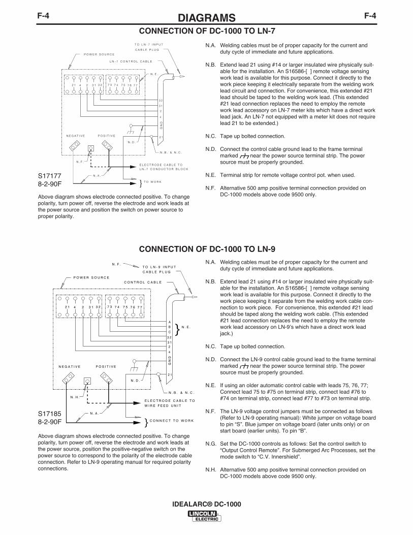
CONNECTION OF DC-1000 TO LN-7
CONNECTION OF DC-1000 TO LN-9
N.A. Welding cables must be of proper capacity for the current andduty cycle of immediate and future applications.
N.B. Extend lead 21 using #14 or larger insulated wire physically suit-able for the installation. An S16586-[ ] remote voltage sensingwork lead is available for this purpose. Connect it directly to thework piece keeping it electrically separate from the welding worklead circuit and connection. For convenience, this extended #21lead should be taped to the welding work lead. (This extended#21 lead connection replaces the need to employ the remotework lead accessory on LN-7 meter kits which have a direct worklead jack. An LN-7 not equipped with a meter kit does not requirelead 21 to be extended.)
N.C. Tape up bolted connection.
N.D. Connect the control cable ground lead to the frame terminalmarked near the power source terminal strip. The powersource must be properly grounded.
N.E. Terminal strip for remote voltage control pot. when used.
N.F. Alternative 500 amp positive terminal connection provided onDC-1000 models above code 9500 only.
N.A. Welding cables must be of proper capacity for the current andduty cycle of immediate and future applications.
N.B. Extend lead 21 using #14 or larger insulated wire physically suit-able for the installation. An S16586-[ ] remote voltage sensingwork lead is available for this purpose. Connect it directly to thework piece keeping it separate from the welding work cable con-nection to work piece. For convenience, this extended #21 leadshould be taped along the welding work cable. (This extended#21 lead connection replaces the need to employ the remotework lead accessory on LN-9ʼs which have a direct work leadjack.)
N.C. Tape up bolted connection.
N.D. Connect the LN-9 control cable ground lead to the frame terminalmarked near the power source terminal strip. The powersource must be properly grounded.
N.E. If using an older automatic control cable with leads 75, 76, 77;Connect lead 75 to #75 on terminal strip, connect lead #76 to#74 on terminal strip, connect lead #77 to #73 on terminal strip.
N.F. The LN-9 voltage control jumpers must be connected as follows(Refer to LN-9 operating manual): White jumper on voltage boardto pin “S”. Blue jumper on voltage board (later units only) or onstart board (earlier units). To pin “B”.
N.G. Set the DC-1000 controls as follows: Set the control switch to“Output Control Remote”. For Submerged Arc Processes, set themode switch to “C.V. Innershield”.
N.H. Alternative 500 amp positive terminal connection provided onDC-1000 models above code 9500 only.
Above diagram shows electrode connected positive. To changepolarity, turn power off, reverse the electrode and work leads atthe power source and position the switch on power source toproper polarity.
Above diagram shows electrode connected positive. To changepolarity, turn power off, reverse the electrode and work leads atthe power source, position the positive-negative switch on thepower source to correspond to the polarity of the electrode cableconnection. Refer to LN-9 operating manual for required polarityconnections.
2 1 4 2 3 1 3 2 7 3 7 4 7 5 7 6 7 7
3 2
3 1
2
4
GN
D
P O W E R S O U R C E
L N - 7 C O N T R O L C A B L E
T O L N - 7 I N P U T
C A B L E P L U G
N E G A T I V E P O S I T I V E 2 1
N . B . & N . C .
N . D .
N . F .
N . A .
E L E C T R O D E C A B L E T O
L N - 7 C O N D U C T O R B L O C K
T O W O R K}
N . E .
2 1 4 2 3 1 3 2 7 3 7 4 7 5 7 6 7 7
3 2
3 12
4
GN
D
P O W E R S O U R C E
C A B L E P L U G
N E G A T I V E P O S I T I V E
2 1
N . B . & N . C .
N . D .
N . A .
E L E C T R O D E C A B L E T O
}
T O L N - 9 I N P U TN . F .
N . H .
W I R E F E E D U N I T
C O N N E C T T O W O R K
A
B
C } N . E .
C O N T R O L C A B L E
S171778-2-90F
S171858-2-90F
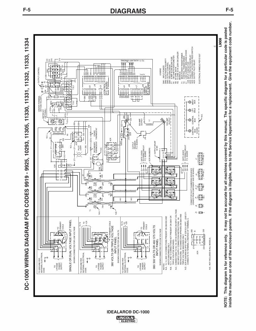
F-5DIAGRAMSF-5
IDEALARC® DC-1000
DC
-100
0 W
IRIN
G D
IAG
RA
M F
OR
CO
DE
S 9
919
- 99
25, 1
0293
, 113
05, 1
1330
, 113
31, 1
1332
, 113
33, 1
1334
NO
TE
: T
his
dia
gra
m is
fo
r re
fere
nce
on
ly.
It m
ay n
ot
be
accu
rate
fo
r al
l mac
hin
es c
ove
red
by
this
man
ual
. T
he
spec
ific
dia
gram
fo
r a
par
ticu
lar
cod
e is
pas
ted
insi
de
the
mac
hin
e o
n o
ne
of
the
encl
osu
re p
anel
s. I
f th
e d
iag
ram
is il
leg
ible
, wri
te t
o t
he
Ser
vice
Dep
artm
ent
for
a re
pla
cem
ent.
Giv
e th
e eq
uip
men
t co
de
nu
mb
er.

F-6DIAGRAMSF-6
IDEALARC® DC-1000
NO
TE
: T
his
diag
ram
is fo
r re
fere
nce
only
. It
may
not
be
accu
rate
for
all m
achi
nes
cove
red
by th
is m
anua
l. T
he s
peci
fic d
iagr
am fo
r a
part
icul
ar c
ode
is p
aste
d in
side
the
mac
hine
on
one
of th
e en
clos
ure
pane
ls.
If th
e di
agra
m is
ille
gibl
e, w
rite
to th
e S
ervi
ce D
epar
tmen
t for
a r
epla
cem
ent.
Giv
e th
e eq
uipm
ent c
ode
num
ber.

NOTES
IDEALARC® DC-1000

NOTES
IDEALARC® DC-1000

WARNING
AVISO DEPRECAUCION
ATTENTION
WARNUNG
ATENÇÃO
Spanish
French
German
Portuguese
Japanese
Chinese
Korean
Arabic
READ AND UNDERSTAND THE MANUFACTURER’S INSTRUCTION FOR THIS EQUIPMENT AND THE CONSUMABLES TO BEUSED AND FOLLOW YOUR EMPLOYER’S SAFETY PRACTICES.
SE RECOMIENDA LEER Y ENTENDER LAS INSTRUCCIONES DEL FABRICANTE PARA EL USO DE ESTE EQUIPO Y LOSCONSUMIBLES QUE VA A UTILIZAR, SIGA LAS MEDIDAS DE SEGURIDAD DE SU SUPERVISOR.
LISEZ ET COMPRENEZ LES INSTRUCTIONS DU FABRICANT EN CE QUI REGARDE CET EQUIPMENT ET LES PRODUITS AETRE EMPLOYES ET SUIVEZ LES PROCEDURES DE SECURITE DE VOTRE EMPLOYEUR.
LESEN SIE UND BEFOLGEN SIE DIE BETRIEBSANLEITUNG DER ANLAGE UND DEN ELEKTRODENEINSATZ DES HER-STELLERS. DIE UNFALLVERHÜTUNGSVORSCHRIFTEN DES ARBEITGEBERS SIND EBENFALLS ZU BEACHTEN.
Do not touch electrically live parts orelectrode with skin or wet clothing.Insulate yourself from work andground.
No toque las partes o los electrodosbajo carga con la piel o ropa moja-da.Aislese del trabajo y de la tierra.
Ne laissez ni la peau ni des vête-ments mouillés entrer en contactavec des pièces sous tension.Isolez-vous du travail et de la terre.
Berühren Sie keine stromführendenTeile oder Elektroden mit IhremKörper oder feuchter Kleidung!Isolieren Sie sich von denElektroden und dem Erdboden!
Não toque partes elétricas e elec-trodos com a pele ou roupa molha-da.Isole-se da peça e terra.
Keep flammable materials away.
Mantenga el material combustiblefuera del área de trabajo.
Gardez à l’écart de tout matérielinflammable.
Entfernen Sie brennbarres Material!
Mantenha inflamáveis bem guarda-dos.
Wear eye, ear and body protection.
Protéjase los ojos, los oídos y elcuerpo.
Protégez vos yeux, vos oreilles etvotre corps.
Tragen Sie Augen-, Ohren- und Kör-perschutz!
Use proteção para a vista, ouvido ecorpo.
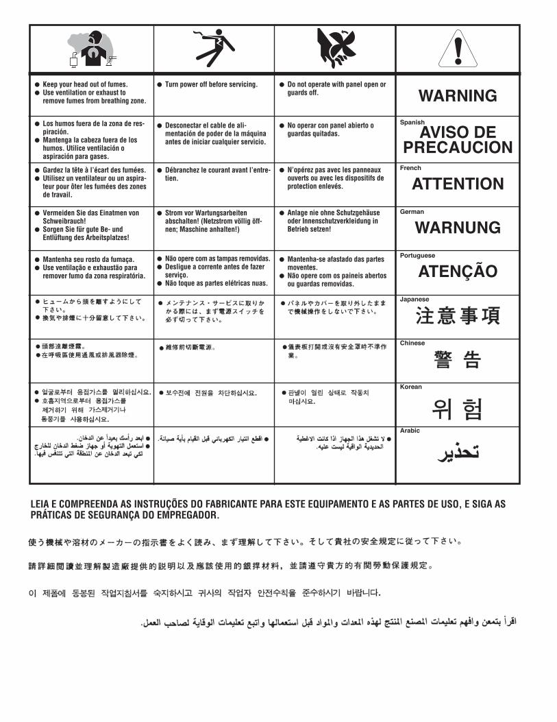
WARNING
AVISO DEPRECAUCION
ATTENTION
WARNUNG
ATENÇÃO
Spanish
French
German
Portuguese
Japanese
Chinese
Korean
Arabic
LEIA E COMPREENDA AS INSTRUÇÕES DO FABRICANTE PARA ESTE EQUIPAMENTO E AS PARTES DE USO, E SIGA ASPRÁTICAS DE SEGURANÇA DO EMPREGADOR.
Keep your head out of fumes.Use ventilation or exhaust toremove fumes from breathing zone.
Los humos fuera de la zona de res-piración.Mantenga la cabeza fuera de loshumos. Utilice ventilación oaspiración para gases.
Gardez la tête à l’écart des fumées.Utilisez un ventilateur ou un aspira-teur pour ôter les fumées des zonesde travail.
Vermeiden Sie das Einatmen vonSchweibrauch!Sorgen Sie für gute Be- undEntlüftung des Arbeitsplatzes!
Mantenha seu rosto da fumaça.Use ventilação e exhaustão pararemover fumo da zona respiratória.
Turn power off before servicing.
Desconectar el cable de ali-mentación de poder de la máquinaantes de iniciar cualquier servicio.
Débranchez le courant avant l’entre-tien.
Strom vor Wartungsarbeitenabschalten! (Netzstrom völlig öff-nen; Maschine anhalten!)
Não opere com as tampas removidas.Desligue a corrente antes de fazerserviço.Não toque as partes elétricas nuas.
Do not operate with panel open orguards off.
No operar con panel abierto oguardas quitadas.
N’opérez pas avec les panneauxouverts ou avec les dispositifs deprotection enlevés.
Anlage nie ohne Schutzgehäuseoder Innenschutzverkleidung inBetrieb setzen!
Mantenha-se afastado das partesmoventes.Não opere com os paineis abertosou guardas removidas.

• Sales and Service through Subsidiaries and Distributors Worldwide •
Cleveland, Ohio 44117-1199 U.S.A. TEL: 216.481.8100 FAX: 216.486.1751 WEB SITE: www.lincolnelectric.com
• World's Leader in Welding and Cutting Products •