Operator's Manual for LaserCAD - Boss Laser · Operator's Manual for LaserCAD. 608 ... All main...
59
Operator's Manual for LaserCAD 608 Trestle Point Sanford, FL 32771 Phone 888-652-1555 • Fax 407-878-0837 www.BOSSLASER.com
Transcript of Operator's Manual for LaserCAD - Boss Laser · Operator's Manual for LaserCAD. 608 ... All main...
Operator's Manual for LaserCAD
608 Trestle PointSanford, FL 32771
Phone 888-652-1555 • Fax 407-878-0837
www.BOSSLASER.com

1.Software InstallationEnter the software installation category
After that, double click “Setup” to start installation.
“LaserCAD”option means installation for LaserCAD“CoreDraw_LaserCut”option means installation for CoreDraw plugin“AutoCAD_LaserCut”option means installation for AutoCAD plugin

Install the USB driver. Once installed successfully, you will have this message appear (as shown below)
Please turn off any anti-virus software or the software may be considered as virus and not run correctly. It will cause installation to fail (this software is NOT a virus of any sort). If it has been stopped by your anti-virus system, there would be some warning words like “Error” or “Can’t Copy Files”. Please try to remove the relative items from your anti-virus files blocked list. Then try again.
Select installation path
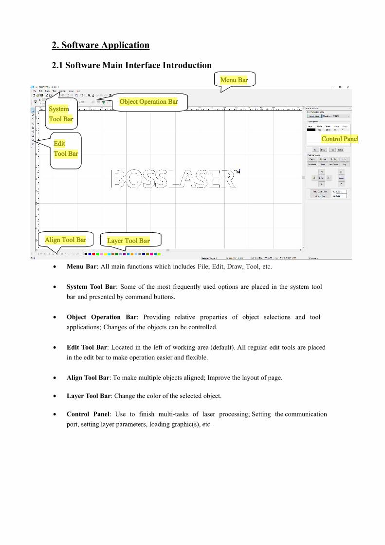
2. Software Application
2.1 Software Main Interface Introduction
• Menu Bar: All main functions which includes File, Edit, Draw, Tool, etc.
• System Tool Bar: Some of the most frequently used options are placed in the system toolbar and presented by command buttons.
• Object Operation Bar: Providing relative properties of object selections and toolapplications; Changes of the objects can be controlled.
• Edit Tool Bar: Located in the left of working area (default). All regular edit tools are placedin the edit bar to make operation easier and flexible.
• Align Tool Bar: To make multiple objects aligned; Improve the layout of page.
• Layer Tool Bar: Change the color of the selected object.
• Control Panel: Use to finish multi-tasks of laser processing; Setting the communicationport, setting layer parameters, loading graphic(s), etc.
Menu Bar
Object Operation BarSystemTool Bar
EditTool Bar
Align Tool Bar Layer Tool Bar
Control Panel
BossLaser2
Highlight
BossLaser2
Highlight
BossLaser2
Highlight
BossLaser2
Highlight
BossLaser2
Highlight
BossLaser2
Highlight
BossLaser2
Highlight

• The preview graphic option helps you to preview the file you selected.
2.2 File Management2.2.1 New FileClick the File menu and select “New File” option or click the system tool bar icon to create a new file.
2.2.2 Open FileClick the File menu and select “Open”option or click the system tool bar icon to find file category then select the file and double click. The opened file suffix is pwj5.

2.2.4 Save as...Click the file menu and select “save as” option to find the file saving category. Then import the file's name and click to save it. The saved file suffix is pwj5.
2.2.5 Import fileClick the File menu and select “Import” option or click the system tool bar icon to find
the file saving category. This software support files with the following suffix: AI, DXF, PLT, DST, DSB, BMP, GIF, JPEG, PNG, MNG, ICO, TIF, TGA, PCX, JBG, JB2, JBC, PGX, RAS, PNM, SKA, and RAW.
2.2.3 Save FileClick the File menu and select “save” option or click the system tool bar to find the file saving icon category. Then import the file’s name and click to save it. The saved file suffix is pwj5.
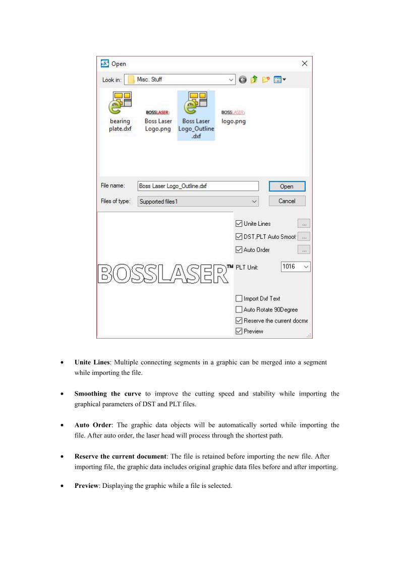
• Unite Lines: Multiple connecting segments in a graphic can be merged into a segmentwhile importing the file.
• Smoothing the curve to improve the cutting speed and stability while importing thegraphical parameters of DST and PLT files.
• Auto Order: The graphic data objects will be automatically sorted while importing thefile. After auto order, the laser head will process through the shortest path.
• Reserve the current document: The file is retained before importing the new file. Afterimporting file, the graphic data includes original graphic data files before and after importing.
• Preview: Displaying the graphic while a file is selected.
2.2.7 Import Machine ConfigurationClick the File menu and select“Import Machine Configuration” option to find the path of the
machine's configuration file. Then double click machine configuration file to accept the changes.
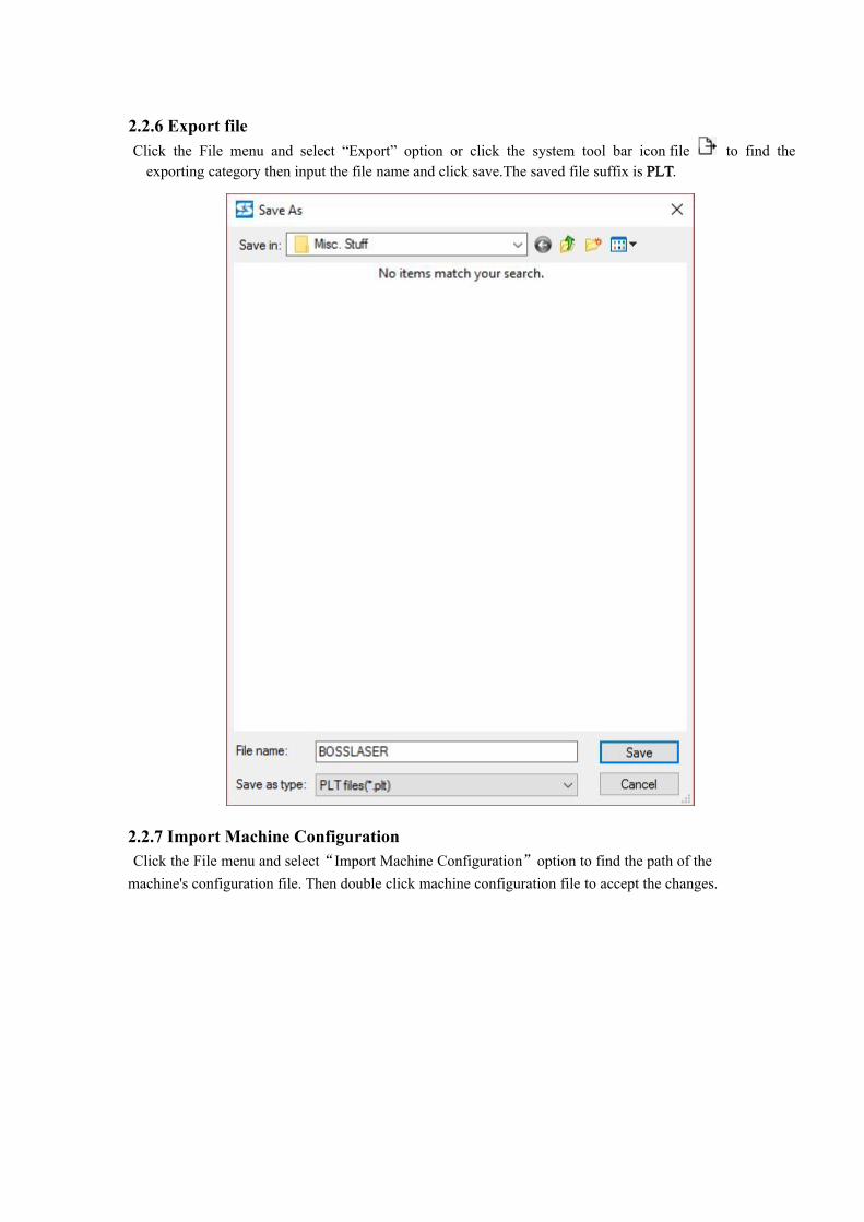
to find the2.2.6 Export fileClick the File menu and select “Export” option or click the system tool bar icon file
exporting category then input the file name and click save.The saved file suffix is PLT.

2.2.8 Export Machine ConfigurationClick the File menu and select “Export Machine Configuration” option to find the path of
saving the machine's configuration file. Then name the file, click save to save it on the destination you have chosen. The exported file suffix is CF5.
2.2.9 Import Software ConfigurationClick the File menu and select “Import Software Configuration” option to find the path of the
machine's software file. Then double click software configuration file to import it. The suffix of the software configuration is qscf.
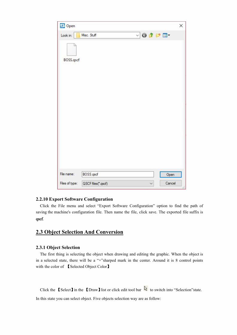
2.2.10 Export Software ConfigurationClick the File menu and select “Export Software Configuration” option to find the path of
saving the machine's configuration file. Then name the file, click save. The exported file suffix is qscf.
2.3 Object Selection And Conversion
2.3.1 Object SelectionThe first thing is selecting the object when drawing and editing the graphic. When the object is
in a selected state, there will be a “×”sharped mark in the center. Around it is 8 control points with the color of 【Selected Object Color】
Click the 【Select】in the 【Draw】list or click edit tool bar to switch into “Selection”state.
In this state you can select object. Five objects selection way are as follow:
1) Click【All Select】in【Edit】list (Shortcuts Ctrl+A) to select all objects.2) Click to select single objectClick object with mouse as follow:
3) Frame selectionHold down the mouse and move. All objects touched by the cursor will be selected.4) Add /Reduce selection objects.
Add: First, select the first object and hold down shift. Then click (or frame select) other objects which you need to add.Reduce: Press shift and click (or frame select) the selected graphic files. Then the clicked (or frame selected) object will be reduced from selected objects.
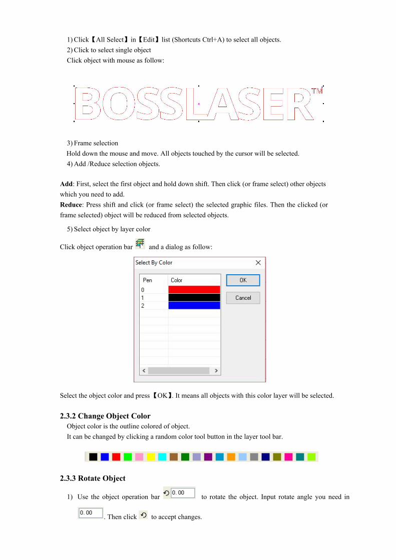
5) Select object by layer color
Click object operation bar and a dialog as follow:
Select the object color and press【OK】. It means all objects with this color layer will be selected.
2.3.2 Change Object ColorObject color is the outline colored of object.It can be changed by clicking a random color tool button in the layer tool bar.
2.3.3 Rotate Object
1) Use the object operation bar to rotate the object. Input rotate angle you need in
. Then click to accept changes.

2) Select the Edit tool bar , double click the object which you need to rotate or tilt and enter
the relative mode. At this moment the control point around the object exchanged into Rotatecontrol arrow and tilt control arrow. As follow:
Move the cursor to rotate arrow and drag the control points along the direction of the arrow controls; during the process, some outline frame wires will follow to rotate. Like the following picture:
Rotate it to your desired position and release the mouse button to accept changes.
2.3.4 Change Object Size
1) Use (Select tool) to click & select the object which needs to be zoomed or changed.Move control points of object to change the object size. This method is easy but with low precision.
2) In the object operation bar (zoom size) input the
horizontal size number and vertical size number and press “Enter”to accept.
Click to . Any changes on one number, the other will change according to the
proportions of the object (Proportional Scaling).
2.4 Edit
2.4.1 UndoClick 【Undo】in 【Edit】list or click to cancel the last operation.
2.4.2 RedoClick 【Redo】in 【Edit】list or click to recover the cancel action.
2.4.3 CutSelect one object and click 【Cut】in 【Edit】list or click to cut a file part.
2.4.4 CopySelect one object and click 【Copy】in 【Edit】list or click to copy a file part.
2.4.5 PasteSelect one object and click 【Paste】in 【Edit】list or click to paste a file part
2.4.6 DeleteSelect one object and click 【Delete】in 【Edit】list to delete a file part
2.4.7 All SelectClick 【All Select】in 【Edit】list to select all file parts in one graphic.
to build a graphic group2.4.8 Group
Select file parts and click 【Group】in 【Edit】list or click with separated selected graphics.
2.4.9 Ungroupto split aSelect needed graphic group and click【Ungroup】 in【Edit】 list or click
completed graphic file group into separated graphics.
2.4.10 All UngroupSelect needed graphic group and click 【Ungroup】in 【Edit】list or click to split All file
group into separated graphics.
2.4.11 Moveand cursor changes into size. Hold down mouse
. Click the graphic with the left mouse button to enlarge
Click 【Move】in 【Edit】list or click left button and you can move the graphic.
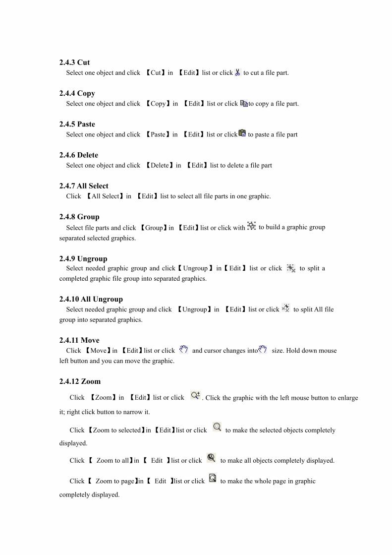
2.4.12 Zoom
Click 【Zoom】in 【Edit】list or click
it; right click button to narrow it.
Click 【Zoom to selected】in 【Edit】list or click to make the selected objects completely
displayed.
Click 【 Zoom to all】in 【 Edit 】list or click to make all objects completely displayed.
to make the whole page in graphic Click【 Zoom to page】in【 Edit 】list or click
completely displayed.
2.4.13 AlignSelect graphic and click 【 Align 】 in 【 Edit 】 list on relative list options or click
to accept changes.
2.4.14 Nudge OffsetSelect graphic and click 【 Align 】in 【 Edit 】list on relative options to make a tiny
adjustment for the graphic.
2.4.15 Convert To LeftoverConvert to leftover belongs to affiliated graphics of an array file. It is used for to add other
graphics in empty places in array layout. In the blank area of an array graphic, add cutting box file to save materials.
2.4.16 Convert Last Row To LeftoverThis option is used to add other graphics in the last row of an array of typesetting.
2.4.17 Light Guide Panel
2.4.18 Clothing Mark
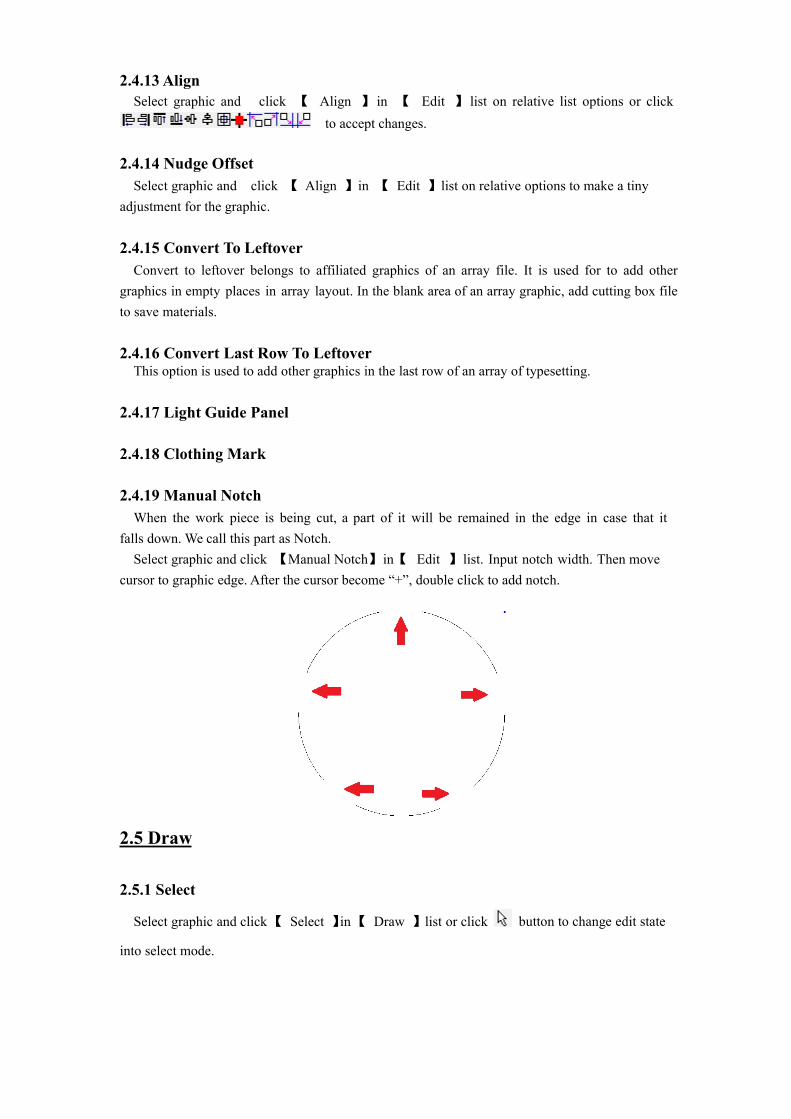
2.4.19 Manual NotchWhen the work piece is being cut, a part of it will be remained in the edge in case that it
falls down. We call this part as Notch.Select graphic and click 【Manual Notch】in【 Edit 】list. Input notch width. Then move
cursor to graphic edge. After the cursor become “+”, double click to add notch.
2.5 Draw
button to change edit state
2.5.1 Select
Select graphic and click【 Select 】in【 Draw 】 list or click
into select mode.

2.5.2 Edit Node
Click 【 Edit Node 】 in 【 Draw 】list or click
operation bar will show tools : ( add node )
button. In the right side of object
(delete node) (connect node)
(separate node).
Use your mouse to select items. Node point of selected file will be presented as small rectangle “ ”. A selected rectangle as follow:
Select points of fileClick selected file or select one point of this file.It is marked as “ ”.
Select node of fileClick the node point of file to select it. It will be marked as “ ”as follow:
Click the selected node of a file. At the same time, press “Shift” button to select multi nodes of file.
Add NodeSelect one point of selected file, as follow:
in object operation bar and the selected pointClick 【 Add Node 】in 【 Edit 】list or click
becomes the added node of the file. As follow:
Selected point
Selected node
Selected point
Selected point addedas node
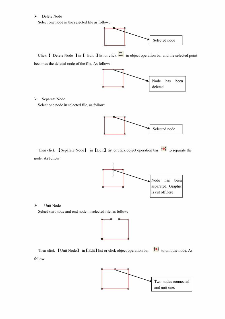
Delete NodeSelect one node in the selected file as follow:
in object operation bar and the selected pointClick【 Delete Node 】 in【 Edit 】 list or click
becomes the deleted node of the file. As follow:
Separate NodeSelect one node in selected file, as follow:
to separate theThen click 【Separate Node】 in【Edit】list or click object operation bar
node. As follow:
Unit NodeSelect start node and end node in selected file, as follow:
to unit the node. AsThen click 【Unit Node】 in【Edit】list or click object operation bar
follow:
Selected node
Node has beendeleted
Selected node
Node has been separated. Graphic is cut off here
Two nodes connectedand unit one.

2.5.3 Line
Click 【Line】 in【Draw】list or click Edit Tool Bar . Then drag the mouse to draw any line.
When drawing a line, press “Ctrl”and move mouse to draw a level line.
2.5.4 Polyline
Click 【Polyline】 in【Draw】list or click Edit Tool Bar . Then drag mouse and click it to
draw any line.
2.5.5 RectangleClick 【Rectangle】 in【Draw】list or click Edit Tool Bar . Then drag mouse to draw any
rectangle.
When drawing a rectangle, press “Ctrl”and move mouse to draw a cube.
2.5.6 EllipseClick【Ellipse】 in【Draw】 list or click Edit Tool Bar .Then drag mouse to draw any ellipse.
When drawing a ellipse, press “Ctrl”and move mouse to draw a circle.
2.5.7 Bezier
Click 【Bezier】 in【Draw】list or click Edit Tool Bar . Then drag mouse to draw a Bezier.
2.5.8 TextClick 【Text 】 in【Draw】list or click Edit Tool Bar . Then Double click mouse left
button in screen, a dialog as follow:
Input characters in dialog and set font and size. Then press OK to add a text to graphic.
2.6 Tool
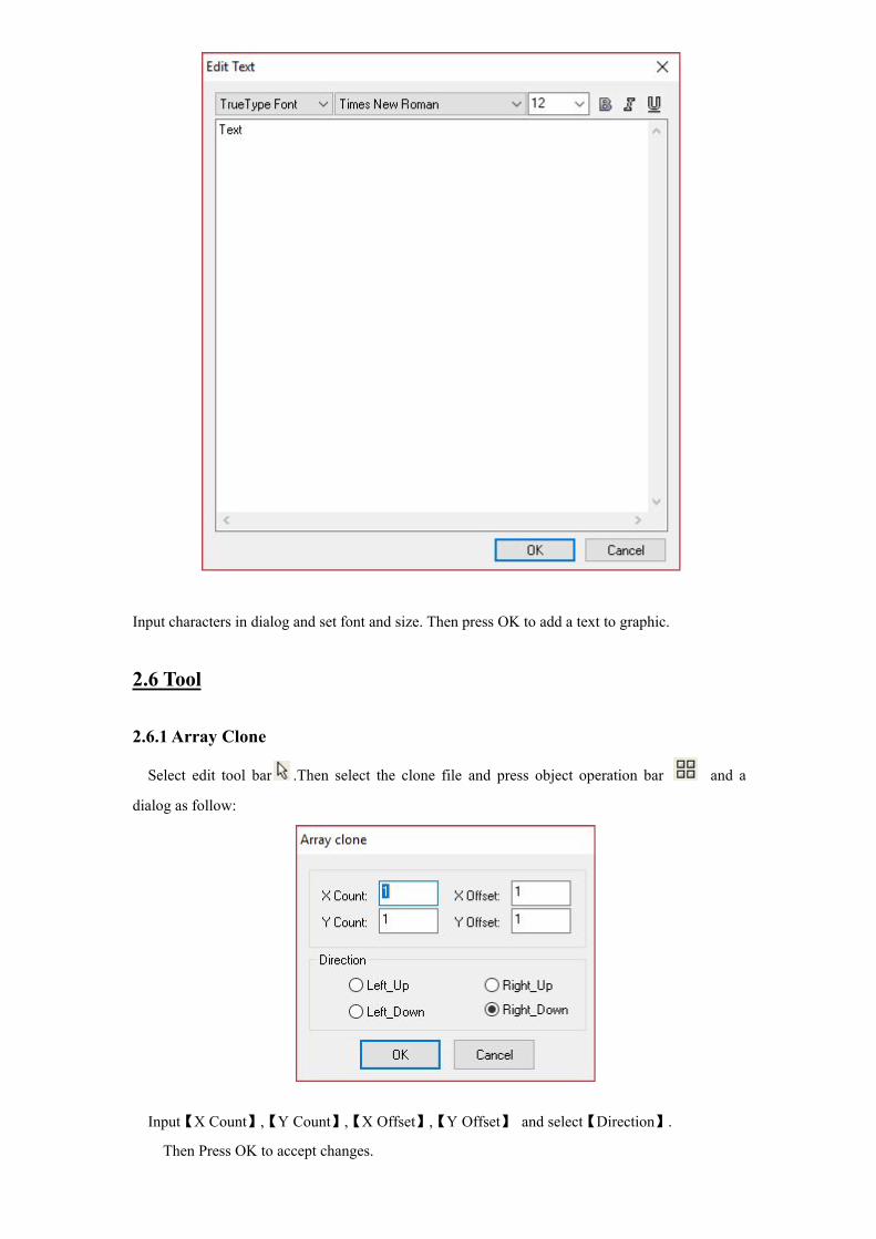
2.6.1 Array Clone
Select edit tool bar .Then select the clone file and press object operation bar and a
dialog as follow:
Input【X Count】,【Y Count】,【X Offset】,【Y Offset】 and select【Direction】.
Then Press OK to accept changes.
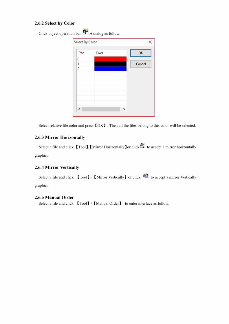
2.6.2 Select by Color
Click object operation bar .A dialog as follow:
Select relative file color and press【OK】. Then all the files belong to this color will be selected.
2.6.3 Mirror Horizontally
Select a file and click【Tool】/【Mirror Horizontally】or click to accept a mirror horizontally
graphic.
2.6.4 Mirror Vertically
Select a file and click 【Tool】/【Mirror Vertically】or click to accept a mirror Vertically
graphic.
2.6.5 Manual OrderSelect a file and click 【Tool】/【Manual Order】 to enter interface as follow:

1) Change serial number of cutting object.• Mouse drag option in 【Manual Order】. Then you could move this option to the position of
the cursor.
• Mouse double click option in 【Manual Order】. Then it could be moved to the top position.
• Click 【Rev_Order】in【Manual Order】will list all items in reverse order
Each Serial Number are different file numbers in 【Manual Order】. The lower the number is, the earlier the file will be processed.
2) Change The Start PointStart point in the file is marked as “ ”. Click anywhere along the file to change the position.3) Change Arrow DirectionCutting direction of object is marked as “ ”.Click【Rev_Dir】in【Manual Order】to make thecutting direction opposite to origin.
2.6.6 Automatic Order【 Automatic Order 】 tool is used for automatically ordering all the objects in the current
document. After that, the motion path of output processing will be the theoretical shortest way.Click 【Tool】/【Automatic Order】. A dialog is as follow. Then Press【OK】

• Order by layer: All file items with the same color will be continuously ordered. (Thismeans the same colored files will be processed all together before the next colored items.)
• Inner to outer: Inner files (or included) will be ranked priority on outer files (includes).(This means the inner files will be processed first, before the outer items.)
• Automation set cut director: Automatically ensure start point and cutting direction of theprocessed file when order graphics.
• Path run region: Files will be ordered as 【Size】 with setting 【Director】.【Path run region】is normally used for an arrangement of a regular array pattern (eg: circular array, a rectangulararray). For these, the【Size】setting is the height of a single graphic in the ordered files.
2.6.7 Smooth Object(s)To Smooth the curve and improve the cutting speed and stability.Click 【Tool】/【Smooth Object(s)】.A dialog is as follow.Then Press 【OK】
The higher the smoothing parameters, the smoother the curve is. However, with more file deformation.

2.6.9 Unite Lines【Unite Lines】tool combine multiple segments into one segment.Click 【Tool】/【Unite Lines】. A dialog is as follow. Then Press【OK】
• Unite Tolerance(mm): Between two segments, if their distance is less than their unitetolerance, they will be merged together.
2.6.8 Delete Repeated Lines【Delete Repeated Lines】can delete overlapping graphics in case of any repeating cutting. Click 【Tool】/【Delete Repeated Lines】. A dialog is as follow. Then Press【OK】

Object cutting starting point will be marked as “ ”. Clicking the object could change the start point. Cutting direction will be marked as “ ”. Arrow direction will show the cutting direction.
2.6.11 Auto Cutting Guide LineWhen drawing or importing graphics, by default, the curve has no cutting guide line. Click 【Tool】/【Auto Cutting Guide_Line】. A dialog is as follow:
2.6.10 Edit Cutting Guide LineClick 【Tool】/【Edit Cutting Guide Line】to enter the interface as follow:
• Cutting In & Out Guide Line: Angle of cutting guide line and starting line.Counterclockwise with positive numbers.
• Auto Confirm direction: When it's not being chosen, you can select guide line direction byhand. When choosing direction inner, lines will be guided from graphic inside. Otherwise willbe from out of graphic.
• Center Guide: Cutting guide lines will be guided from center of graphic.

2.6.12 Image Invert
Select edit tool .Then the select file which needs to be inverted.
Click 【Tool】 /【Image Invert】or click object operation bar .
2.6.13 Image Dither
Select edit tool bar . Then select the bitmap object to be treated. Click
【Tool】 / 【Image Dither】in list or click object operation bar . A dialog as follow:

2.6.14 Create Image Block
2.6.15 Create Image Outline
Select edit tool bar and select the file graphic to begin creating an image outline. Then
click 【Tool】 /【Create Image Outline】as follow:
2.6.16 Close Check
Select edit tool bar .Then select the vector object which need to do a close check.
Click【Tool】 /【Close Check】in list as follow:
Note: Results may vary depending on the quality of the original image.
BossLaser2
Highlight
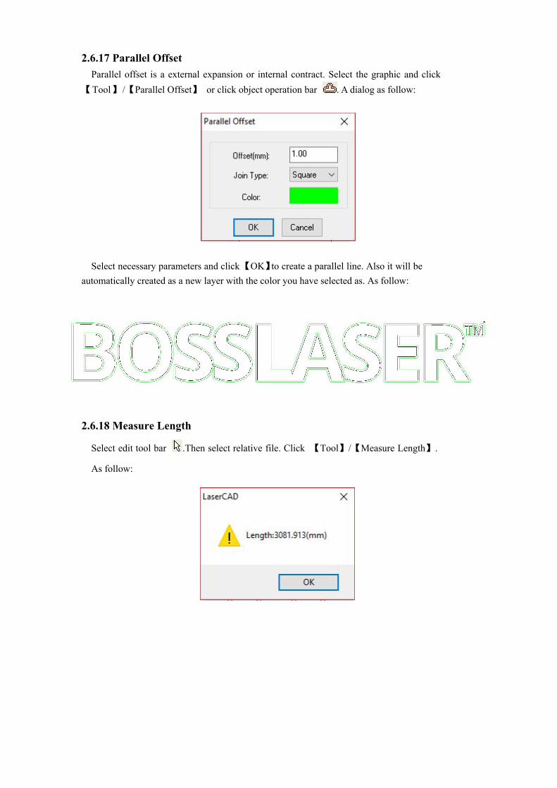
2.6.17 Parallel OffsetParallel offset is a external expansion or internal contract. Select the graphic and click
【Tool】 /【Parallel Offset】 or click object operation bar . A dialog as follow:
Select necessary parameters and click【OK】 to create a parallel line. Also it will be automatically created as a new layer with the color you have selected as. As follow:
2.6.18 Measure Length
Select edit tool bar .Then select relative file. Click 【Tool】/【Measure Length】.
As follow:

2.6.19 Estimate Work Time
Select edit tool bar . Then select relative file. Click 【Tool】/【Estimate Work Time】 or
click system tool bar to show the working time of processing. As follow:
2.6.20 Simulate
Select edit tool bar . Then select the relative file. Click【Tool】 / 【Simulate 】 or click
system tool bar to analog output the machining process. As follow:
2.7 Options
to enter the system parameters2.7.1 System Options
Click【Options】/【System Options】or click system tool bar setting interface.

• Nudge Offset(mm): The single movement distance when the pressing keyboard “←”, “→”,“↑”, “↓” to move the selected file.
• Paste Offset(mm): The offset distance of pasting a copy of selected object to current view.
• Language: The language used in the type of software
• Speed Unit: The unit type used for all items in software related to speed.
• Machine Zero: The current machine zero point (Or limit switch position). Thisparameter should be the same as actual machine zero point. Otherwise the processed file maybe left-right or up-down reversed.
• Page Zero: Zero point in software graphic. Or when the mouse is moved to the rightbottom corner of the workspace, the state bar presents X=0, Y=0.
• Selected’ Color: Outline color of the selected object.
• Show Grid: Graphic will be shown with grid model.
• Simulating show objects of engraving: Simulating shows layer with stuffed engraving way.
When the amount of data in the graphic sculpture is large, it will lead a slower speed of software display. Regularly not recommend this option.
• Always show the welcome screen at launch: When it is selected, there will always be asoftware default welcome interface after starting.
2.7.1.1 Work Space

2.7.1.2 Advance Functions:
2) Divided Cutting
• Enable divided cutting• Auto control of two laser head• Max Divide Height (mm)
1) Two Head Configuration
3) Speed Optimize Of cutting
• Enable

2.7.1.3 Work Parameters
1) Curve Disperse(mm)• Curve Disperse(mm): Parameters of curve smooth. The smaller it is, the higher graphic
precision, but the slower computing speed. It effects the processing speed. Normally formaterials like acrylic, you can choose a smaller number. Otherwise please use default0.10.
2) Circle Speed:• Circle Speed: System automatically determines if the processed circle is limited on cutting speed. Then
process it by relative diameter date with different speed. Under the right parameter settings, the cuttingeffect of the circle will be greatly improved. To Click【Add】,【Delete】【Modify】and set the parameters.
3) Engrave reserve offset:• Engrave reserve offset: During the double-way engraving graphics and due to the
mechanical backlash, it may lead to a uneven edge graphics after scanned. So using theengraving reserve offset to fix it. A specific speed can relate to specific engraving reserveoffset. Normally speaking, more speed is needed with the higher engraving reserve offset.This parameters could be positive or negative.
When speed is 200mm/s, reserve offset is 0.3mm; When speed is less than 200mm/s,the relationship between speed and reserve offset is proportional. So when speed is100mm/s, reserve offset is 0.30*(100/200)=0.15mm
When speed is 300mm/s, reserve offset is 0.50mm; When speed is within 200~300mm/s,the relationship between speed and reserve offset is proportional. So when speed is250mm/s, reserve offset is 0.30+(300-250)/(300-200)×(0.5-0.3)=0.40mm
When speed is more than 300mm/s, reserve offset is the same as when speed is 300mm/s(or 0.5mm)

2.7.1.4 Manufacturer Parameters
X,Y,Z,U axes parameters (Z axis is for up down axis,and U axis is for auto feeding axis).Click【Z/U Axes Options】you can set up parameters of Z and U axis.
• Um/Pulse(um): The absolute distance value (unit: um) that a signal sent by the motor relateto motion axis movement. The processed graphic size with error Um/Pulse setting will notthe same as expected.
• Pulse Edge: The trigger edge of the motor driver making the motor spin. It will lead acutting dislocation if it has the wrong parameter settings.
• Datum: Axis movement direction during reset. When the machine datums and does NOTmove the top right corner of the machine, please rewrite this parameter.
1) X,Y axes parameters

• Key direction: Direction of LCD panel button movement. If the direction is reversed, rewrite the parameter to correct the direction.
• Range: Working area of machine; Axis max working distance.
• Start Speed: Speed of motion axis from still state to starting state. The more numbers, the higher the starting speed, but will increase the instability of the machine. Please adjust accordingly. Classical setting ranges in 5~20mm/s.
• Max_Acc: Acceleration of motion axis doing adding or reducing speed. If too high of an acceleration, it will cause the motor to skip steps and/or shake. If too low of an acceleration, it may cause a low working speed and slow down whole program. For an axis with a big inertia, like beams corresponding to the Y-axis, a classical setting parameters range from 800 to 3000mm/s2. For an axis with small inertia, like the X-axis, a classical setting parameters range from 10000 to 20000mm/s2.
• Max_Speed: The max speed motion axis could be up to which decided by motor driving ability and inertia. When doing engraving task,the engraving speed could not beyond the max speed of relative axis. When doing cutting task,the max cutting speed could not beyond the max speed of X and Y axes. Controller will protect speed within the max speed limitation if met any over-high speed requirement.
2) I/O Switches• Water Protect: Controller board water protection interface for Laser 1-Protect and Laser-
Protect. Enable【Water Protect】and the system will, in real-time, monitor the two waterprotection signals. When one of them presents in a high level state, the processing task will bepaused and laser will be turned off. “Water protection error”will be shown in LCD display.
• Open Protect: Controller board open protection interface is IN1. Enable【Open Protect】and the system will, in real-time, monitor the signal. When it changes into low level state, theprocessing task will be paused. When it is in a high level state, the paused task will becontinued.
• Foot Switch: Controller board foot switch interface is IN2. Enable【Foot Switch】systemwill, in real-time, monitor the signal. When the signal exchanges from high level to low level,the states will be switches (from pause to work or from work to pause).
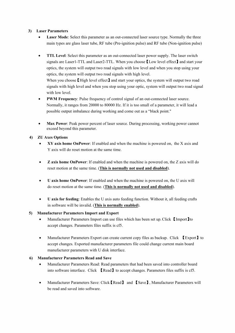
4) ZU Axes Options• XY axis home OnPower: If enabled and when the machine is powered on, the X axis and
Y axis will do reset motion at the same time.
• Z axis home OnPower: If enabled and when the machine is powered on, the Z axis will doreset motion at the same time. (This is normally not used and disabled).
• U axis home OnPower: If enabled and when the machine is powered on, the U axis willdo reset motion at the same time. (This is normally not used and disabled).
• U axis for feeding: Enables the U axis auto feeding function. Without it, all feeding craftsin software will be invalid. (This is normally enabled).
5) Manufacturer Parameters Import and Export• Manufacturer Parameters Import can use files which has been set up. Click 【Import】to
accept changes. Parameters files suffix is cf5.
• Manufacturer Parameters Export can create current copy files as backup. Click 【Export】toaccept changes. Exported manufacturer parameters file could change current main boardmanufacturer parameters with U disk interface.
6) Manufacturer Parameters Read and Save• Manufacturer Parameters Read: Read parameters that had been saved into controller board
into software interface. Click 【Read】to accept changes. Parameters files suffix is cf5.
• Manufacturer Parameters Save: Click【Read】 and 【Save】, Manufacturer Parameters willbe read and saved into software.
3) Laser Parameters• Laser Mode: Select this parameter as an out-connected laser source type. Normally the three
main types are glass laser tube, RF tube (Pre-ignition pulse) and RF tube (Non-ignition pulse)
• TTL Level: Select this parameter as an out-connected laser power supply. The laser switchsignals are Laser1-TTL and Laser2-TTL. When you choose【Low level effect】and start youroptics, the system will output two road signals with low level and when you stop using youroptics, the system will output two road signals with high level.When you choose【High level effect】and start your optics, the system will output two roadsignals with high level and when you stop using your optic, system will output two road signalwith low level.
• PWM Frequency: Pulse frequency of control signal of an out-connected laser source.Normally, it ranges from 20000 to 80000 Hz. If it is too small of a parameter, it will lead apossible output imbalance during working and come out as a “black point."
• Max Power: Peak power percent of laser source. During processing, working power cannotexceed beyond this parameter.

2.7.1.5 User Parameters
1) Work Control Parameters
• Space_Speed: Laser head motion speed when the laser is not outputting during workingprocess. This parameter is limited by【Max_Speed】in manufacturer parameters.
• Start_Speed: Laser head motion speed from running to still-phase during working process.This parameter is limited by【Start_Speed】in manufacturer parameters.
• Speed_Factor: Rounding speed item during working process. The bigger it is ,the fasterworking speed, but can increase instability to the machine. It ranges between 0 to 5. Thecurrent default 2.
• Space_Jerk: Changing speed of space acceleration during working process. The bigger it is,the faster space speed, but can increase instability to the machine. It is normally set as 10000to 60000.
• Cut_Jerk: Changing speed of cutting acceleration during working process. The bigger it is,the faster space speed, but can increase instability to the machine. It is normally set as 5000to 50000.
• Min_Acc: Mini acceleration of axis motion during working process.
• Cut_Acc: Max acceleration of motion laser head when the laser is outputting during workingprocess. Normally set below 1500.
• Space_Acc: Max acceleration of motion laser head when the laser is NOT outputting duringworking process. Normally set below 2000.

• Engrave_Acc: Max acceleration of laser head when engraving. Normally set higherthan 8000. If it is too small of a parameter, it will lead a long distance between startingspeed increase to engraving speed and cause the engraving oversize to fail.
• Instant recovery: One press button to set user parameters. You can choose “SlowerParams”, “Normal Params”, “Faster Params” and “Fastest Params”.
2) System Config Parameters• X/Y_Home_Speed: Machine speed reset to origin point. Normally ranges between 40 to 80.
If it is too large, it will lead a overload impact and probably damage the limit switch(es).
• Z_Home_Speed: Z axis (up & down axis) reset to origin point.
• U_Home_Speed: U axis (feeding axis) reset to origin point.
• Z_Work_Speed: Z axis motion speed during working process.
• U_Work_Speed: U axis motion speed during working process.
• Key_Move_Speed: Axis movement speed when pressing keys on LCD panel.
• RunBox_Speed: Laser head motion speed along graphic outline box.
• ClipBox_Speed: Cutting speed on graphics outline box.
3) User parameters import and export.• User parameters import could be used for all adjusted user parameters files. Click【Import】to
accept changes.
• User parameters export can create current copy files as backup. Click【Export】to acceptchanges. Exported user parameters file could change current main board manufacturerparameters with U disk interface.
User Parameters Read: Read parameters saved in controller main board to software interface. Click【Read】to accept changes. Click【Save】, user parameters will be saved into software.
4) User parameters read and save.

Click 【Auto_conver Calculation】software will do automatic array as the working area and graphic size with the most economical way of materials and make graphics filled in whole working size.
Graphics needed to do an array process will be dealt with the array parameters setting. Click【Option】/【Array output options】to enter it as follow:
2.7.2 Array output options
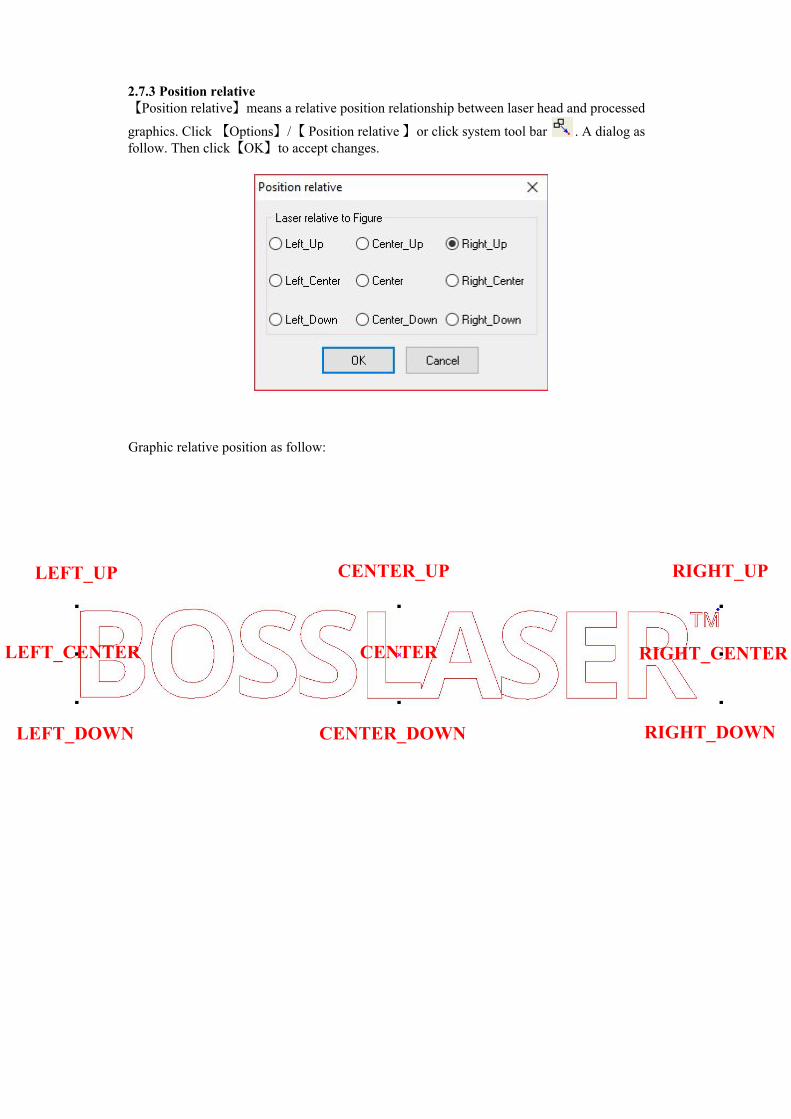
Graphic relative position as follow:
2.7.3 Position relative【Position relative】means a relative position relationship between laser head and processed
graphics. Click 【Options】/【 Position relative 】or click system tool bar . A dialog as follow. Then click【OK】to accept changes.
LEFT_UP CENTER_UP RIGHT_UP
RIGHT_CENTER
RIGHT_DOWNCENTER_DOWNLEFT_DOWN
LEFT_CENTER CENTER

2.7.4 Default ParametersBack to default software parameters. When it is selected, reset machine property parameters
will be required.
2.8 ViewView list is used to tune out or hide the toolbar
2.8.1 How to tune out the hidden tool bar?When the menu bar is not hidden, you can choose relative tool bar in【View】list to tune them out. When the menu bar is hidden, click the mouse right button in the space area of state bar and select the relative tool bar to accept changes. Press the mouse right button down on the tool bar title and stay held. Then drag it to software top to fix the toolbar. As follow:
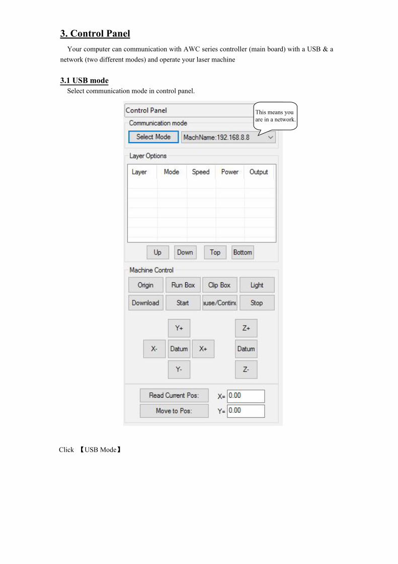
3. Control PanelYour computer can communication with AWC series controller (main board) with a USB & a
network (two different modes) and operate your laser machine
3.1 USB modeSelect communication mode in control panel.
Click 【USB Mode】
This means youare in a network.
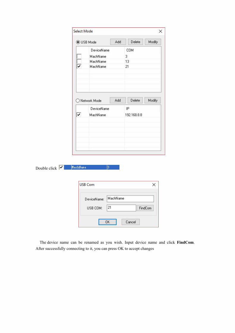
Double click
The device name can be renamed as you wish. Input device name and click FindCom. After successfully connecting to it, you can press OK to accept changes
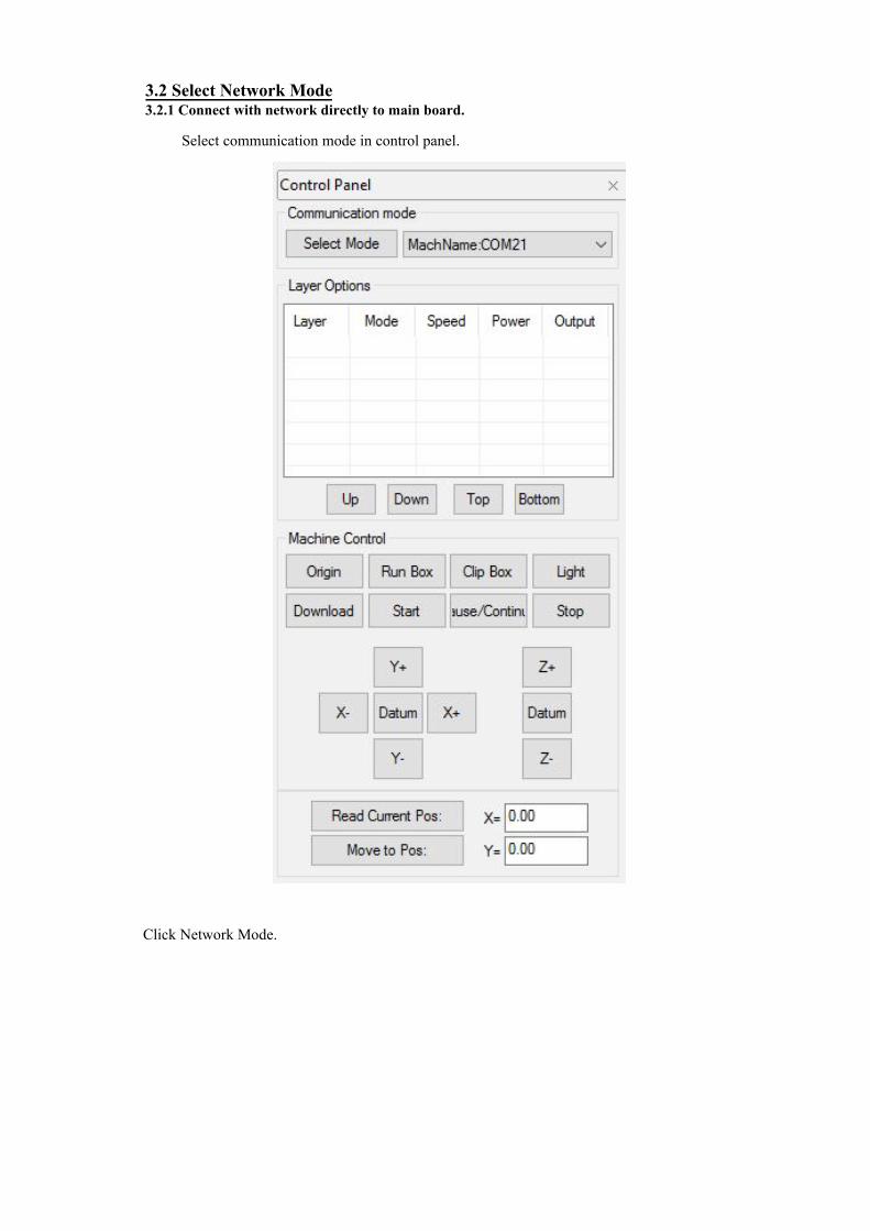
Click Network Mode.
Select communication mode in control panel.
3.2 Select Network Mode3.2.1 Connect with network directly to main board.

Double click
The device name can be renamed as you wish. Input IP address in controller main board panel and press OK to accept changes.
Let's take Windows 10 as an example, search for Network and Sharing Center.
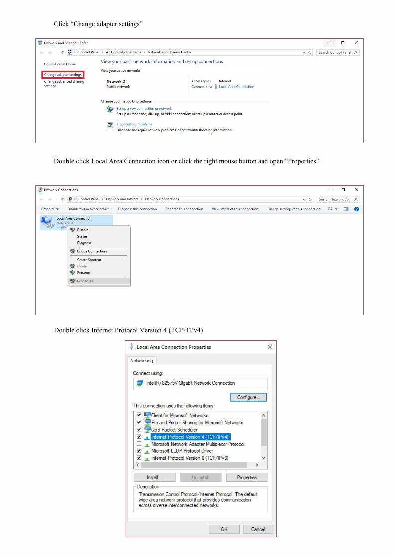
Click “Change adapter settings”
Double click Local Area Connection icon or click the right mouse button and open “Properties”
Double click Internet Protocol Version 4 (TCP/TPv4)

Select the following IP address. The former three IP addresses must be the same as what in controller main board. The number circled in red can be any one number between 0-255 except the main board's IP address. Then Click【OK】to accept changes.
3.2.2 Connection through the router to main board.Refer to the picture above; IP address set as obtain IP address automatically. The three IP
addresses must be the same as what is on controller main board. The number circled in red can be any one number between 0-255 except main board IP address (just like the above example).
Again, let's take Windows 10 as an example, search for Network and Sharing Center.

Double Click the WLAN icon or click the mouse right button to open “Properties”.
Click “Change adapter settings”

When you double click the WLAN icon, a window (as shown below) will pop up. Then click on "Properties."
Or you can click on the right mouse button on the WLAN icon, then select "Properties."

Set parameters with the same rule.
Double click Internet Protocol Version 4 (TCP/TPv4)
The three IP addresses must be the same as what is on controller main board. This IP at the end can be any one number between 0-255 except main board IP address

3.3 Setting layer parameters.1) Layer parameters
Locate the “Output” bar (under Layer Options; located at the top right of the software), each layer
will have white-check box under Output. will output the layer and will NOT output the layer.
Double click any row on the parameters list (such as
The following window will appear as shown below:
• Layer: The current layer you have selected where you can change the parameters for thatcolor. At any time, you can select the different layers on the left side to change in between.
• Work Mode: Includes “Cut,” “Engrave,” “Cut after engrave,” “Hole,” and “Pen Run.” If thecurrent file format is a BMP or bitmap layer, then it will show “Engrave” under WorkMode as the only option. (A bitmap layer is only used for laser engraving).
• If Air Switch Open: Blowing air when cutting on this layer.
)

2) Cut ParametersSelect “Cut” or “Cut after engrave” in 【Work Mode】 , cut parameters will be enable. As
follow:
• Speed: Working speed of laser head during cutting.
• MaxPower(%): Machine working power (unit is in percentage). Related to AWC controllerpanel Laser 1 power.
• MinPower(%): In variable motion, this power is done at the lowest speed. Related to AWCcontroller panel Laser 1 power.
To set any cut advance parameters , click and a dialog will show as follow:
• Overlap(mm): The mechanical deviation; if the file did not completely close, i.e showinga gap, this parameter can help solve this problem. However, it should not be adjust toomuch. A suggestion might be to improve your mechanical parts' precision to fix it OR itmight be the file itself.
• Open Delay(ms): Set open delay time before laser output.
• Close Delay(ms): Set close delay time after laser shut down.
• Dash Line: Cutting a graphic with a dash-line way. Enable it and you can set the dash linelength and single solid length.
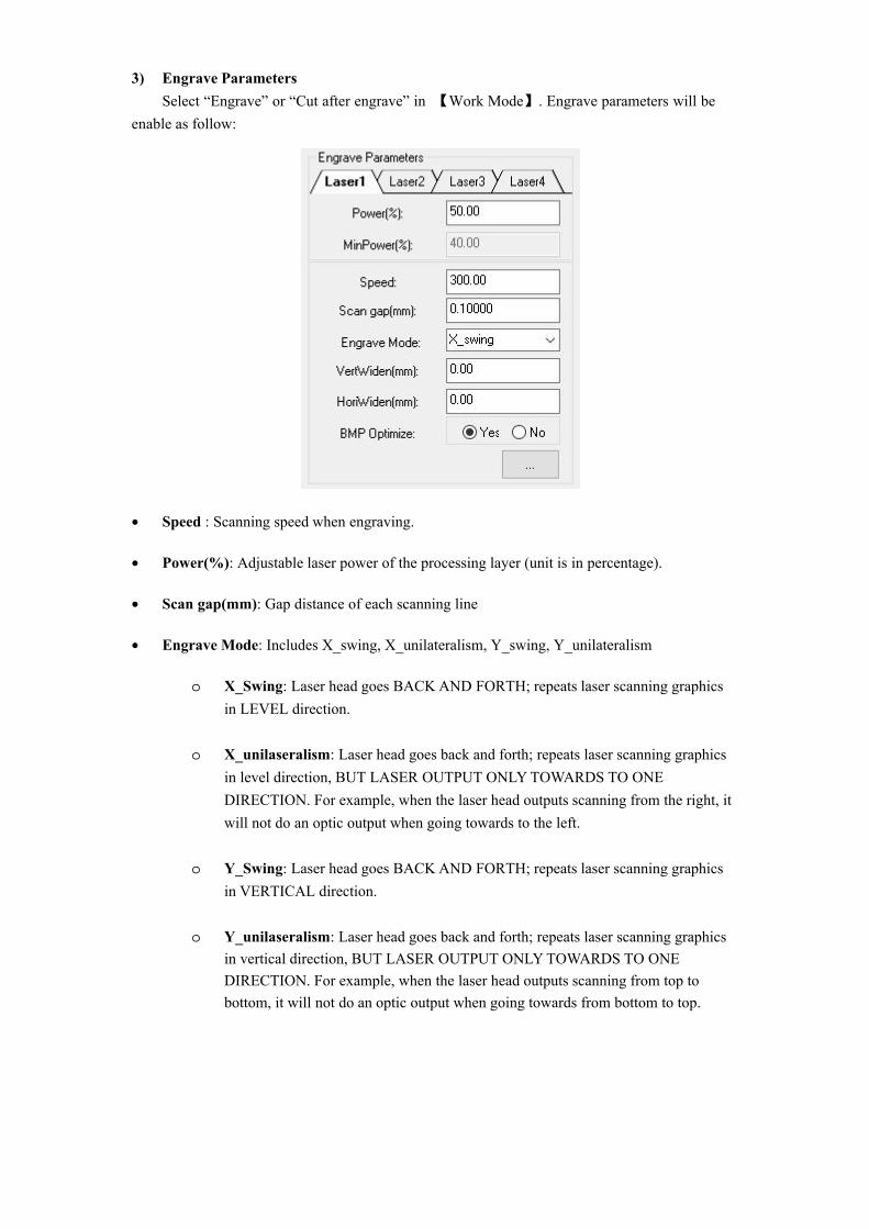
3) Engrave ParametersSelect “Engrave” or “Cut after engrave” in 【Work Mode】. Engrave parameters will be
enable as follow:
• Speed : Scanning speed when engraving.
• Power(%): Adjustable laser power of the processing layer (unit is in percentage).
• Scan gap(mm): Gap distance of each scanning line
• Engrave Mode: Includes X_swing, X_unilateralism, Y_swing, Y_unilateralism
o X_Swing: Laser head goes BACK AND FORTH; repeats laser scanning graphics in LEVEL direction.
o X_unilaseralism: Laser head goes back and forth; repeats laser scanning graphics in level direction, BUT LASER OUTPUT ONLY TOWARDS TO ONE DIRECTION. For example, when the laser head outputs scanning from the right, it will not do an optic output when going towards to the left.
o Y_Swing: Laser head goes BACK AND FORTH; repeats laser scanning graphics in VERTICAL direction.
o Y_unilaseralism: Laser head goes back and forth; repeats laser scanning graphics in vertical direction, BUT LASER OUTPUT ONLY TOWARDS TO ONE DIRECTION. For example, when the laser head outputs scanning from top to bottom, it will not do an optic output when going towards from bottom to top.

If GradeEngrave : Choose “Yes” and enable【Grade Length (mm)】. Grade engraving schematic diagram:
• Grade Length(mm): or “slope” in diagram.
4) HoleSelect “Hole” in 【Work Mode】to enable hole parameters.
Look for .Press 【Hole Parameters】and a dialog as
follow:
• Power(%): Adjustable laser power when the layer is being processed
• Speed: Laser head movement speed
• Interval(mm): Distance of each hole
• Time(s): Each period that laser head will stay when drilling
Click to enter the engrave advance parameters
A:Grade width. B:Top depth C:Total depth
A
B
C

5) Pen Parameters
• Speed: Movement speed of pen.
3.3.1 Adjust layers processing orderThe default processing order in the layer list is from top to bottom. If you need change
it, just select any one layer and press to accept changes.
Only select【Order by layer】in route optimization parameters, this function will work.
3.4 Machine Control【Machine Control】includes control operations on importing graphics, starting process and
other simple machine functions.
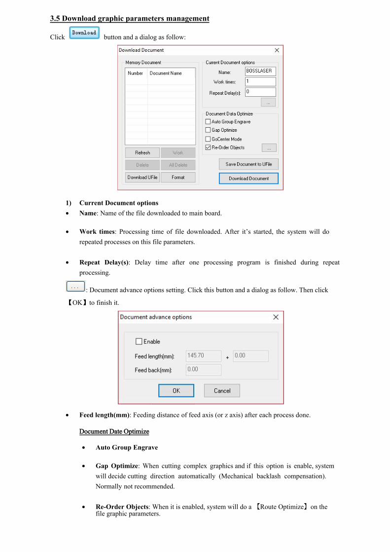
3.5 Download graphic parameters management
Click button and a dialog as follow:
1) Current Document options• Name: Name of the file downloaded to main board.
• Work times: Processing time of file downloaded. After it’s started, the system will dorepeated processes on this file parameters.
• Repeat Delay(s): Delay time after one processing program is finished during repeatprocessing.
: Document advance options setting. Click this button and a dialog as follow. Then click
【OK】to finish it.
• Feed length(mm): Feeding distance of feed axis (or z axis) after each process done.
Document Date Optimize
• Auto Group Engrave
• Gap Optimize: When cutting complex graphics and if this option is enable, systemwill decide cutting direction automatically (Mechanical backlash compensation).Normally not recommended.
• Re-Order Objects: When it is enabled, system will do a 【Route Optimize】on thefile graphic parameters.

2) Export file parametersYou can save it as an off-line file (or *.ud5 file). Then copy it to an U disk to the controllermain board. Press【Save document to Ufile】and dialog as follow:
Input a file name and press【Save】to accept it.OR you can directly download the file parameters via USB or network mode to the controller main board, just click【Download Document】.
to start the processing program on it.
button. This file will be removed
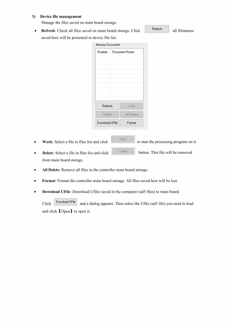
• Work: Select a file in files list and click
• Delete: Select a file in files list and click
from main board storage.
• All Delete: Remove all files in the controller main board storage.
• Format: Format the controller main board storage. All files saved here will be lost.
• Download UFile: Download Ufiles saved in the computer (ud5 files) to main board.
Click and a dialog appears. Then select the Ufile (ud5 file) you need to load
and click【Open】to open it.
3) Device file managementManage the files saved on main board storage.
all filenames• Refresh: Check all files saved on main board storage. Click
saved here will be presented in device file list.
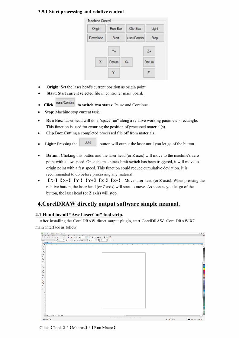
• Run Box: Laser head will do a "space run" along a relative working parameters rectangle.This function is used for ensuring the position of processed material(s).
• Clip Box: Cutting a completed processed file off from materials.
• Light: Pressing the button will output the laser until you let go of the button.
• Datum: Clicking this button and the laser head (or Z axis) will move to the machine's zeropoint with a low speed. Once the machine's limit switch has been triggered, it will move toorigin point with a fast speed. This function could reduce cumulative deviation. It isrecommended to do before processing any material.
• 【X-】【X+】【Y-】【Y+】【Z-】【Z+】: Move laser head (or Z axis). When pressing therelative button, the laser head (or Z axis) will start to move. As soon as you let go of thebutton, the laser head (or Z axis) will stop.
4.CorelDRAW directly output software simple manual.
4.1 Hand install “AwcLaserCut” tool strip.After installing the CorelDRAW direct output plugin, start CorelDRAW. CorelDRAW X7
main interface as follow:
Click【Tools】/【Macros】/【Run Macro】
3.5.1 Start processing and relative control
• Origin: Set the laser head's current position as origin point.• Start: Start current selected file in controller main board.
• Click to switch two states: Pause and Continue.
• Stop: Machine stop current task.

A dialog as follow:
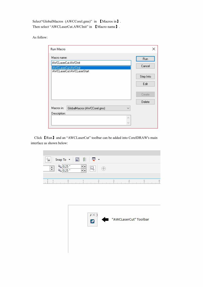
Click 【Run】 and an “AWCLaserCut” toolbar can be added into CorelDRAW's main interface as shown below:
Select“GlobalMacros (AWCCorel.gms)” in 【Macros in】.Then select “AWCLaserCut.AWCInit” in 【Macro name】.
As follow:

After it has been added successfully, when restart CorelDRAW, “AWCLaserCut”tool strip will always appear in tool bar.
4.2 Shows hidden “AWCLaserCut” tool stripWhen using CorelDRAW with the LaserCAD plugin, the “AWCLaserCut”toolbar may not be visible.
To make it visible again:Click tool bar with mouse right button. A drop-down menu should appear. Click【AWCLaserCut】 as
follow:
Drag the “AWCLaserCut” tool strip with your mouse to the toolbar. As follow: