Operator’s Manual - Erreur générique · This Operator’s Manual is an impo rtant part of your...
29
772C0692 (01/04) PRINTED IN UNITED-STATES Hydrostatic Lawn Tractor Operator’s Manual IMPORTANT: READ SAFETY RULES AND INSTRUCTIONS CAREFULLY WHITE OUTDOOR, 60 OTTAWA STREET SOUTH, KITCHENER, ONT. N2G 3S7 Models: LT-18H LT-180H LT-200H WLT-180
Transcript of Operator’s Manual - Erreur générique · This Operator’s Manual is an impo rtant part of your...

772C0692 (01/04)PRINTED IN UNITED-STATES
Hydrostatic Lawn Tractor
Operator’s Manual
IMPORTANT: READ SAFETYRULES AND INSTRUCTIONSCAREFULLY
WHITE OUTDOOR, 60 OTTAWA STREET SOUTH, KITCHENER, ONT. N2G 3S7
Models: LT-18HLT-180HLT-200HWLT-180

2
TABLE OF CONTENTSPAGE
FINDING YOUR MODEL NUMBER . . . . . . . . . . . . . . . . . . . . . . . . . . . . . . . . . . . . . . . . . . . . . . . . . . . . . . . 2CALLING CUSTOMER SUPPORT . . . . . . . . . . . . . . . . . . . . . . . . . . . . . . . . . . . . . . . . . . . . . . . . . . . . . . . 2IMPORTANT SAFE OPERATION PRACTICES . . . . . . . . . . . . . . . . . . . . . . . . . . . . . . . . . . . . . . . . . . . . . 3SAFETY LABELS FOUND ON YOUR UNIT . . . . . . . . . . . . . . . . . . . . . . . . . . . . . . . . . . . . . . . . . . . . . . . . 6ATTACHMENTS & ACCESSORIES . . . . . . . . . . . . . . . . . . . . . . . . . . . . . . . . . . . . . . . . . . . . . . . . . . . . . . 6SLOPE GAUGE . . . . . . . . . . . . . . . . . . . . . . . . . . . . . . . . . . . . . . . . . . . . . . . . . . . . . . . . . . . . . . . . . . . . . . 7TRACTOR SET-UP . . . . . . . . . . . . . . . . . . . . . . . . . . . . . . . . . . . . . . . . . . . . . . . . . . . . . . . . . . . . . . . . . . . 8CONTROLS . . . . . . . . . . . . . . . . . . . . . . . . . . . . . . . . . . . . . . . . . . . . . . . . . . . . . . . . . . . . . . . . . . . . . . . . 11OPERATION. . . . . . . . . . . . . . . . . . . . . . . . . . . . . . . . . . . . . . . . . . . . . . . . . . . . . . . . . . . . . . . . . . . . . . . . 14ADJUSTMENTS . . . . . . . . . . . . . . . . . . . . . . . . . . . . . . . . . . . . . . . . . . . . . . . . . . . . . . . . . . . . . . . . . . . . . 18MAINTENANCE . . . . . . . . . . . . . . . . . . . . . . . . . . . . . . . . . . . . . . . . . . . . . . . . . . . . . . . . . . . . . . . . . . . . . 20LUBRICATION . . . . . . . . . . . . . . . . . . . . . . . . . . . . . . . . . . . . . . . . . . . . . . . . . . . . . . . . . . . . . . . . . . . . . . 21SERVICE . . . . . . . . . . . . . . . . . . . . . . . . . . . . . . . . . . . . . . . . . . . . . . . . . . . . . . . . . . . . . . . . . . . . . . . . . . 22OFF-SEASON STORAGE . . . . . . . . . . . . . . . . . . . . . . . . . . . . . . . . . . . . . . . . . . . . . . . . . . . . . . . . . . . . . 26TROUBLESHOOTING GUIDE . . . . . . . . . . . . . . . . . . . . . . . . . . . . . . . . . . . . . . . . . . . . . . . . . . . . . . . . . . 27PARTS LIST/PIÈCES DÉTACHÉES . . . . . . . . . . . . . . . . . . . . . . . . . . . . . . . . . . . . . . . . . . . . . . . . . . . . . 28WARRANTY . . . . . . . . . . . . . . . . . . . . . . . . . . . . . . . . . . . . . . . . . . . . . . . . . . . . . . . . . . . . . . . . . . . . . . . 50
FINDING MODEL NUMBERThis Operator’s Manual is an important part of your new garden tractor. It will help you assemble, prepare and maintain the unit for best performance. Please read and understand what it says.
Before you start assembling your new equipment, please locate the model plate on the equipment and copy the information from it in the space provided below. The information on the model plate is very important if you need help from your authorized dealer.
• You can locate the model number by looking beneath the seat. A sample model plate is explained below.
CALLING CUSTOMER SUPPORTIf you are having difficulty assembling this product or if you have any question regarding thecontrols, operation or maintenance of this unit, please call your service dealer.
Please have your unit’s model number and serial number ready when you call.
WHITE OUTDOOR CANADAKITCHENER, ON N2G 4J1
XXXXXXXXXX XXXXXXXXXXX
Model NumberNuméro de modèle
Serial NumberNuméro de série
This is where your model number will be.
This is where your serial number will be.
Copy the model number here:
Copy the serial number here:
3
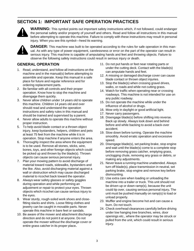
SECTION 1: IMPORTANT SAFE OPERATION PRACTICES
WARNING: This symbol points out important safety instructions which, if not followed, could endangerthe personal safety and/or property of yourself and others. Read and follow all instructions in this manualbefore attempting to operate this machine. Failure to comply with these instructions may result in personalinjury. When you see this symbol—heed its warning.
DANGER: This machine was built to be operated according to the rules for safe operation in this man-ual. As with any type of power equipment, carelessness or error on the part of the operator can result in serious injury. This machine is capable of amputating hands and feet and throwing objects. Failure to observe the following safety instructions could result in serious injury or death.
GENERAL OPERATION1. Read, understand, and follow all instructions on the
machine and in the manual(s) before attempting to assemble and operate. Keep this manual in a safe place for future and regular reference and for ordering replacement parts.
2. Be familiar with all controls and their proper operation. Know how to stop the machine and disengage them quickly.
3. Never allow children under 14 years old to operate this machine. Children 14 years old and over should read and understand the operation instructions and safety rules in this manual and should be trained and supervised by a parent.
4. Never allow adults to operate this machine without proper instruction.
5. To help avoid blade contact or a thrown object injury, keep bystanders, helpers, children and pets at least 75 feet from the machine while it is in operation. Stop machine if anyone enters the area.
6. Thoroughly inspect the area where the equipment is to be used. Remove all stones, sticks, wire, bones, toys, and other foreign objects which could be picked up and thrown by the blade(s). Thrown objects can cause serious personal injury.
7. Plan your mowing pattern to avoid discharge of material toward roads, sidewalks, bystanders and the like. Also, avoid discharging material against a wall or obstruction which may cause discharged material to ricochet back toward the operator.
8. Always wear safety glasses or safety goggles during operation and while performing an adjustment or repair to protect your eyes. Thrown objects which ricochet can cause serious injury to the eyes.
9. Wear sturdy, rough-soled work shoes and close-fitting slacks and shirts. Loose fitting clothes and jewelry can be caught in movable parts. Never operate this machine in bare feet or sandals.
10. Be aware of the mower and attachment discharge direction and do not point it at anyone. Do not operate the mower without the discharge cover or entire grass catcher in its proper place.
11. Do not put hands or feet near rotating parts or under the cutting deck. Contact with the blade(s) can amputate hands and feet.
12. A missing or damaged discharge cover can cause blade contact or thrown object injuries.
13. Stop the blade(s) when crossing gravel drives, walks, or roads and while not cutting grass.
14. Watch for traffic when operating near or crossing roadways. This machine is not intended for use on any public roadway.
15. Do not operate the machine while under the influence of alcohol or drugs.
16. Mow only in daylight or good artificial light.17. Never carry passengers.18. Disengage blade(s) before shifting into reverse.
Back up slowly. Always look down and behind before and while backing to avoid a back-over accident.
19. Slow down before turning. Operate the machine smoothly. Avoid erratic operation and excessive speed.
20. Disengage blade(s), set parking brake, stop engine and wait until the blade(s) come to a complete stop before removing grass catcher, emptying grass, unclogging chute, removing any grass or debris, or making any adjustments.
21. Never leave a running machine unattended. Always turn off blade(s), place transmission in neutral, set parking brake, stop engine and remove key before dismounting.
22. Use extra care when loading or unloading the machine into a trailer or truck. This unit should not be driven up or down ramp(s), because the unit could tip over, causing serious personal injury. The unit must be pushed manually on ramp(s) to load or unload properly.
23. Muffler and engine become hot and can cause a burn. Do not touch.
24. Check overhead clearances carefully before driving under low hanging tree branches, wires, door openings etc., where the operator may be struck or pulled from the unit, which could result in serious injury.

4
25. Disengage all attachment clutches, depress the brake pedal completely and shift into neutral before attempting to start engine.
26. Your machine is designed to cut normal residential grass of a height no more than 10”. Do not attempt to mow through unusually tall, dry grass (e.g., pasture) or piles of dry leaves. Dry grass or leaves may contact the engine exhaust and/or build up on the mower deck presenting a potential fire hazard.
27. Use only accessories and attachments approved for this machine by the machine manufacturer. Read, understand and follow all instructions provided with the approved accessory or attachment.
28. Data indicates that operators, age 60 years and above, are involved in a large percentage of riding mower-related injuries. These operators should evaluate their ability to operate the riding mower safely enough to protect themselves and others from serious injury.
29. If situations occur which are not covered in this manual, use care and good judgment. Contact your authorized dealer for assistance.
SLOPE OPERATION Slopes are a major factor related to loss of control and tip-over accidents which can result in severe injury or death. All slopes require extra caution. If you cannot back up the slope or if you feel uneasy on it, do not mow it.
For your safety, use the slope gauge included as part of this manual to measure slopes before operating this unit on a sloped or hilly area. If the slope is greater than 15 degrees as shown on the slope gauge, do not operate this unit on that area or serious injury could result.
DO:1. Mow up and down slopes, not across. Exercise
extreme caution when changing direction on slopes.
2. Watch for holes, ruts, bumps, rocks, or other hidden objects. Uneven terrain could overturn the machine. Tall grass can hide obstacles.
3. Use slow speed. Choose a low enough speed setting so that you will not have to stop or shift while on the slope. Tires may lose traction on slopes even though the brakes are functioning properly.Always keep machine in gear when going down slopes to take advantage of engine braking action.
4. Follow the manufacturer’s recommendations for wheel weights or counterweights to improve stability.
5. Use extra care with grass catchers or other attachments. These can change the stability of the machine.
6. Keep all movement on the slopes slow and gradual. Do not make sudden changes in speed or direction. Rapid engagement or braking could cause the front of the machine to lift and rapidly flip over backwards which could cause serious injury.
7. Avoid starting or stopping on a slope. If tires lose traction, disengage the blade(s) and proceed slowly straight down the slope.
DO NOT: 1. Do not turn on slopes unless necessary; then, turn
slowly and gradually downhill, if possible.2. Do not mow near drop-offs, ditches or
embankments. The mower could suddenly turn over if a wheel is over the edge of a cliff, ditch, or if an edge caves in.
3. Do not try to stabilize the machine by putting your foot on the ground.
4. Do not use a grass catcher on steep slopes. 5. Do not mow on wet grass. Reduced traction could
cause sliding.6. Do not shift to neutral and coast downhill. Over-
speeding may cause the operator to lose control of the machine resulting in serious injury or death.
7. Do not tow heavy pull behind attachments (e.g. loaded dump cart, lawn roller, etc.) on slopes greater than 5 degrees. When going down hill, the extra weight tends to push the tractor and may cause you to loose control. (e.g. tractor may speed up, braking and steering ability are reduced, attachment may jack-knife and cause tractor to overturn).
CHILDREN1. Tragic accidents can occur if the operator is not
alert to the presence of children. Children are often attracted to the machine and the mowing activity. They do not understand the dangers. Never assume that children will remain where you last saw them.
a. Keep children out of the mowing area and in watchful care of a responsible adult other than the operator.
b. Be alert and turn machine off if a child enters the area.
c. Before and while backing, look behind and down for small children.
d. Never carry children, even with the blade(s) shut off. They may fall off and be seriously injured or interfere with safe machine operation.
e. Use extreme care when approaching blind corners, doorways, shrubs, trees or other objects that may block your vision of a child who may run into the machine.
f. Disengage the cutting blade(s) before shifting in reverse. The “No-Cut-In Reverse”

5
feature is a reminder not to cut in reverse and to help avoid back over accidents. Do not defeat it.
g. Keep children away from hot or running engines. They can suffer burns from a hot muffler.
h. Remove key when machine is unattended to prevent unauthorized operation.
i. Never allow children under 14 years old to operate the machine. Children 14 years old and over should read and understand the operation instructions and safety rules in this manual and should be trained and supervised by a parent.
TOWING1. Tow only with a machine that has a hitch designed
for towing. Do not attach towed equipment except at the hitch point.
2. Follow the manufacturers recommendation for weight limits for towed equipment and towing on slopes.
3. Never allow children or others in or on towed equipment.
4. On slopes, the weight of the towed equipment may cause loss of traction and loss of control.
5. Travel slowly and allow extra distance to stop.6. Do not shift to neutral and coast downhill.
SERVICESAFE HANDLING OF GASOLINE:
1. To avoid personal injury or property damage use extreme care in handling gasoline. Gasoline is extremely flammable and the vapors are explosive. Serious personal injury can occur when gasoline is spilled on yourself or your clothes which can ignite. Wash your skin and change clothes immediately.
a. Use only an approved gasoline container.b. Never fill containers inside a vehicle or on a
truck or trailer bed with a plastic liner. Always place containers on the ground away from your vehicle before filling.
c. When practical, remove gas-powered equipment from the truck or trailer and refuel it on the ground. If this is not possible, then refuel such equipment on a trailer with a portable container, rather than from a gasoline dispenser nozzle.
d. Keep the nozzle in contact with the rim of the fuel tank or container opening at all times until fueling is complete. Do not use a nozzle lock-open device.
e. Extinguish all cigarettes, cigars, pipes and other sources of ignition.
f. Never fuel machine indoors.g. Never remove gas cap or add fuel while the
engine is hot or running. Allow engine to cool at least two minutes before refueling.
h. Never over fill fuel tank. Fill tank to no more than ½ inch below bottom of filler neck to allow space for fuel expansion.
i. Replace gasoline cap and tighten securely.j. If gasoline is spilled, wipe it off the engine and
equipment. Move unit to another area. Wait 5 minutes before starting the engine.
k. To reduce fire hazards, keep machine free of grass, leaves, or other debris build-up. Clean up oil or fuel spillage and remove any fuel soaked debris.
l. Never store the machine or fuel container inside where there is an open flame, spark or pilot light as on a water heater, space heater, furnace, clothes dryer or other gas appliances.
m. Allow a machine to cool at least 5 minutes before storing.
GENERAL SERVICE:
1. Never run an engine indoors or in a poorly ventilated area. Engine exhaust contains carbon monoxide, an odorless, and deadly gas.
2. Before cleaning, repairing, or inspecting, make certain the blade(s) and all moving parts have stopped. Disconnect the spark plug wire and ground against the engine to prevent unintended starting.
3. Periodically check to make sure the blades come to complete stop within approximately (5) five seconds after operating the blade disengagement control. If the blades do not stop within the this time frame, your unit should be serviced professionally by an authorized dealer.
4. Check brake operation frequently as it is subjected to wear during normal operation. Adjust and service as required.
5. Check the blade(s) and engine mounting bolts at frequent intervals for proper tightness. Also, visually inspect blade(s) for damage (e.g., excessive wear, bent, cracked).Replace the blade(s) with the original equipment manufacturer’s (O.E.M.) blade(s) only, listed in this manual. “Use of parts which do not meet the original equipment specifications may lead to improper performance and compromise safety!”
6. Mower blades are sharp. Wrap the blade or wear gloves, and use extra caution when servicing them.
7. Keep all nuts, bolts, and screws tight to be sure the equipment is in safe working condition.
8. Never tamper with the safety interlock system or other safety devices. Check their proper operation regularly.
9. After striking a foreign object, stop the engine, disconnect the spark plug wire(s) and ground against the engine. Thoroughly inspect the machine for any damage. Repair the damage before starting and operating.

6
10. Never attempt to make adjustments or repairs to the machine while the engine is running.
11. Grass catcher components and the discharge cover are subject to wear and damage which could expose moving parts or allow objects to be thrown.For safety protection, frequently check components and replace immediately with original equipment manufacturer’s (O.E.M.) parts only, listed in this manual. “Use of parts which do not meet the origi-
nal equipment specifications may lead to improper performance and compromise safety!”
12. Do not change the engine governor settings or over-speed the engine. The governor controls the maximum safe operating speed of the engine.
13. Maintain or replace safety and instruction labels, as necessary.
14. Observe proper disposal laws and regulations for gas, oil, etc. to protect the environment.
WARNING: YOUR RESPONSIBILITY Restrict the use of this power machine to persons who read,understand and follow the warnings and instructions in this manual and on the machine.
Safety Labels found on your unit
SECTION 2: ATTACHMENTS & ACCESSORIESThe following attachments and accessories are compatible for your lawn tractor. See the your authorized dealer for information regarding price and availability.
NOTE: Your lawn tractor is NOT designed for use with any type of ground-engaging attachments (e.g. tiller orplow). Use of this type of equipment WILL void the tractor’s warranty.
MODEL DESCRIPTIONOEM-190-116 Mulch Kit (For 38” and 42” Decks)OEM-190-118 Mulch Kit (For 46” Decks)OEM-190-180 Twin Bagger Grass Collector 38” and 42” DecksOEM-190-182 Twin Bagger Grass Collector 46” DecksOEM-190-603 FastAttach™ Grille Guard (mounts on front of tractor)OEM-190-604 TracPac™ Storage Container (mounts on rear of tractor)OEM-190-607 Deluxe SunshadeOEM-190-822 FastAttach™ 46-inch Front Dozer BladeOEM-190-823 42-inch Two-stage Snow Thrower
S30011
MAX 20% S30544
7
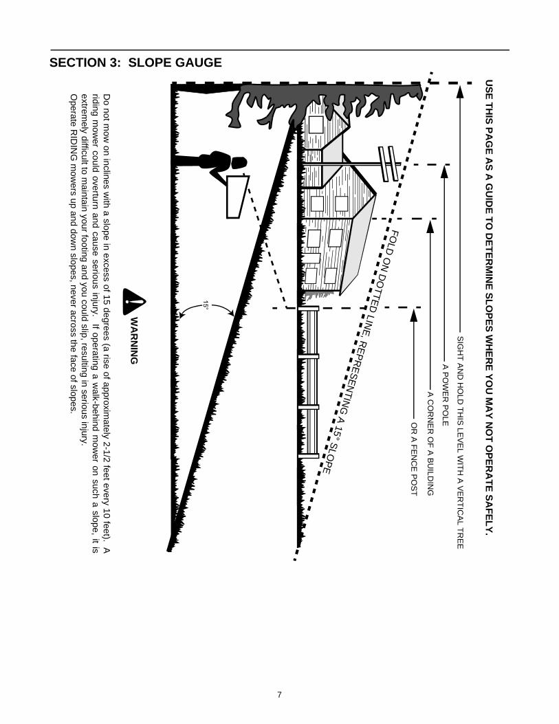
SECTION 3: SLOPE GAUGE
15°
SIG
HT
AN
D H
OLD
TH
IS LE
VE
L WIT
H A
VE
RT
ICA
L TR
EE
A P
OW
ER
PO
LE
A C
OR
NE
R O
F A
BU
ILDIN
G
OR
A F
EN
CE
PO
ST
FO
LD O
N D
OT
TE
D LIN
E, R
EP
RE
SE
NT
ING
A 15° S
LOP
E
US
E T
HIS
PA
GE
AS
A G
UID
E T
O D
ET
ER
MIN
E S
LO
PE
S W
HE
RE
YO
U M
AY
NO
T O
PE
RA
TE
SA
FE
LY
.
Do not m
ow on inclines w
ith a slope in excess of 15 degrees (a rise of approximately 2-1/2 feet every 10 feet). A
riding mow
er could overturn and cause serious injury. If operating a walk-behind m
ower on such a slope, it is
extremely difficult to m
aintain your footing and you could slip, resulting in serious injury.O
perate RID
ING
mow
ers up and down slopes, never across the face of slopes.
WA
RN
ING

8
SECTION 4: TRACTOR SET-UP
NOTE: Reference to RIGHT or LEFT side of thetractor in this manual is observed from operator’sposition.
ATTACHING THE BATTERY CABLES
NOTE: The battery cables may or may not beattached on your unit. If the cables are not attached,please follow the instructions below.
NOTE: The positive battery terminal is marked Pos.(+). The negative battery terminal is marked Neg. (–).
• The positive cable (heavy red wire) is secured tothe positive battery terminal (+) with a hex bolt andhex nut at the factory. Make certain that the rubberboot covers the terminal to help protect it fromcorrosion.
• Remove the hex bolt and wing nut from thenegative cable.
• Remove the black plastic cover, if present, from thenegative battery terminal and attach the negativecable (heavy black wire) to the negative batteryterminal (–) with the bolt and wing nut.
• Make certain the battery retainer rod is in positionover the battery, securing it in place. See Figure 1.
Figure 1
NOTE: If the battery is put into service after the dateshown on top of battery, charge the battery asinstructed on page 23 of this manual prior to operatingthe tractor.
ATTACHING THE STEERING WHEELIn the event your tractor was crated with the steeringwheel and the seat removed for shipping reasons, usethe following instructions to properly assemble theparts.
WARNING: Do NOT operate the tractorwithout first attaching both the steeringwheel AND the seat. Doing so could resultin serious injury to the operator.
NOTE: There are two different styles of steeringwheel cap. See Figure 2. Styles vary by model.
• Using your hands, place the tractor’s front tires inposition for straight-ahead travel.
• Remove the steering wheel cap from the center ofthe steering wheel. Be careful not to lose the hexscrew and bell washer found beneath it.
• Place the steering wheel (in position for straight-ahead travel) directly onto the steering shaft foundin the center of the tractor’s dash.
• Place the bell washer (cupped side DOWN) overthe steering shaft.
• Thread the hex screw into the steering shaft andtighten securely.
• Reinsert the steering wheel cap in the center of thesteering wheel. Refer to Figure 2.
Figure 2
Shoulder Bolt
WingNut
RubberBoot
PositiveTerminal
NegativeTerminal
Battery
BatteryRetainer Rod
Steering
Hex Bolt
SteeringShaft
& Washer
Wheel Cap
9
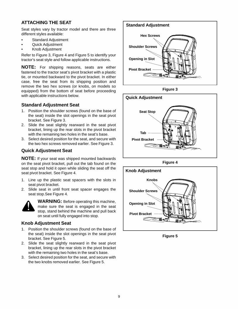
ATTACHING THE SEATSeat styles vary by tractor model and there are threedifferent styles available:
• Standard Adjustment • Quick Adjustment • Knob Adjustment
Refer to Figure 3, Figure 4 and Figure 5 to identify yourtractor’s seat style and follow applicable instructions.
NOTE: For shipping reasons, seats are eitherfastened to the tractor seat’s pivot bracket with a plastictie, or mounted backward to the pivot bracket. In eithercase, free the seat from its shipping position andremove the two hex screws (or knobs, on models soequipped) from the bottom of seat before proceedingwith applicable instructions below.
Standard Adjustment Seat1. Position the shoulder screws (found on the base of
the seat) inside the slot openings in the seat pivotbracket. See Figure 3.
2. Slide the seat slightly rearward in the seat pivotbracket, lining up the rear slots in the pivot bracketwith the remaining two holes in the seat’s base.
3. Select desired position for the seat, and secure withthe two hex screws removed earlier. See Figure 3.
Quick Adjustment Seat
NOTE: If your seat was shipped mounted backwardson the seat pivot bracket, pull out the tab found on theseat stop and hold it open while sliding the seat off theseat pivot bracket. See Figure 4.
1. Line up the plastic seat spacers with the slots inseat pivot bracket.
2. Slide seat in until front seat spacer engages theseat stop.See Figure 4.
WARNING: Before operating this machine,make sure the seat is engaged in the seatstop, stand behind the machine and pull backon seat until fully engaged into stop.
Knob Adjustment Seat1. Position the shoulder screws (found on the base of
the seat) inside the slot openings in the seat pivotbracket. See Figure 5.
2. Slide the seat slightly rearward in the seat pivotbracket, lining up the rear slots in the pivot bracketwith the remaining two holes in the seat’s base.
3. Select desired position for the seat, and secure withthe two knobs removed earlier. See Figure 5.
Figure 3
Figure 4
Figure 5
Standard Adjustment
Hex Screws
Pivot Bracket
Shoulder Screws
Opening in Slot
Quick Adjustment
Seat Stop
Tab
Pivot Bracket
Knob Adjustment
Knobs
Pivot Bracket
Shoulder Screws
Opening in Slot
10
GAS AND OIL FILL-UPThe gasoline tank is located under the hood and has acapacity of either two or three gallons. Do not overfill.
WARNING: Use extreme care whenhandling gasoline. Gasoline is extremelyflammable and the vapors are explosive.Never fuel machine indoors or while theengine is hot or running. Extinguishcigarettes, cigars, pipes, and other sources ofignition.
Service the engine with gasoline and oil as instructed in the separate engine manual packed with your tractor. Read instructions carefully.
IMPORTANT: Your tractor is shipped with oil;however, you MUST check the oil level beforeoperating. Be careful not to overfill. Overfilling with oilmay cause the engine to smoke. This will result in poorengine performance and could cause permanentengine damage.
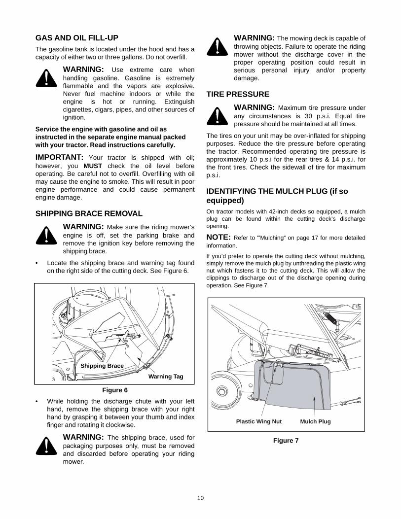
SHIPPING BRACE REMOVAL
WARNING: Make sure the riding mower’sengine is off, set the parking brake andremove the ignition key before removing theshipping brace.
• Locate the shipping brace and warning tag foundon the right side of the cutting deck. See Figure 6.
Figure 6
• While holding the discharge chute with your lefthand, remove the shipping brace with your righthand by grasping it between your thumb and indexfinger and rotating it clockwise.
WARNING: The shipping brace, used forpackaging purposes only, must be removedand discarded before operating your ridingmower.
WARNING: The mowing deck is capable ofthrowing objects. Failure to operate the ridingmower without the discharge cover in theproper operating position could result inserious personal injury and/or propertydamage.
TIRE PRESSURE
WARNING: Maximum tire pressure underany circumstances is 30 p.s.i. Equal tirepressure should be maintained at all times.
The tires on your unit may be over-inflated for shippingpurposes. Reduce the tire pressure before operatingthe tractor. Recommended operating tire pressure isapproximately 10 p.s.i for the rear tires & 14 p.s.i. forthe front tires. Check the sidewall of tire for maximump.s.i.
IDENTIFYING THE MULCH PLUG (if so equipped)On tractor models with 42-inch decks so equipped, a mulchplug can be found within the cutting deck’s dischargeopening.
NOTE: Refer to '”Mulching“ on page 17 for more detailedinformation.
If you’d prefer to operate the cutting deck without mulching,simply remove the mulch plug by unthreading the plastic wingnut which fastens it to the cutting deck. This will allow theclippings to discharge out of the discharge opening duringoperation. See Figure 7.
Figure 7
Shipping Brace
Warning Tag
Plastic Wing Nut Mulch Plug
11
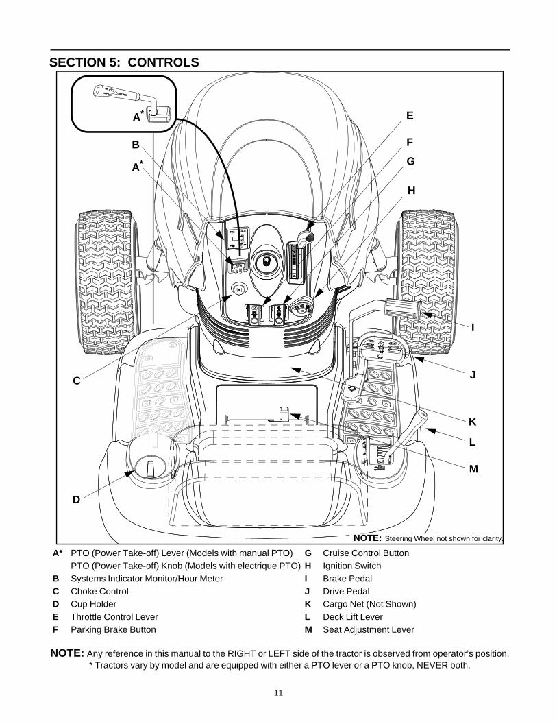
SECTION 5: CONTROLS
NOTE: Any reference in this manual to the RIGHT or LEFT side of the tractor is observed from operator’s position.* Tractors vary by model and are equipped with either a PTO lever or a PTO knob, NEVER both.
A* PTO (Power Take-off) Lever (Models with manual PTO) G Cruise Control Button PTO (Power Take-off) Knob (Models with electrique PTO) H Ignition Switch
B Systems Indicator Monitor/Hour Meter I Brake PedalC Choke Control J Drive PedalD Cup Holder K Cargo Net (Not Shown)E Throttle Control Lever L Deck Lift LeverF Parking Brake Button M Seat Adjustment Lever
H
E
B
C
G
F
D
K
J
I
L
NOTE: Steering Wheel not shown for clarity.
P
1/10
P
+
A*
A*
M
12
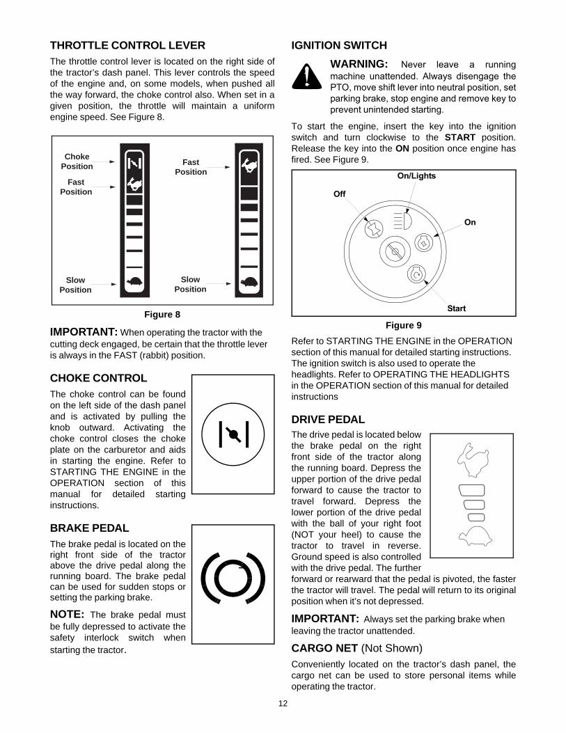
THROTTLE CONTROL LEVERThe throttle control lever is located on the right side ofthe tractor’s dash panel. This lever controls the speedof the engine and, on some models, when pushed allthe way forward, the choke control also. When set in agiven position, the throttle will maintain a uniformengine speed. See Figure 8.
Figure 8
IMPORTANT: When operating the tractor with the cutting deck engaged, be certain that the throttle lever is always in the FAST (rabbit) position.
CHOKE CONTROLThe choke control can be foundon the left side of the dash paneland is activated by pulling theknob outward. Activating thechoke control closes the chokeplate on the carburetor and aidsin starting the engine. Refer toSTARTING THE ENGINE in theOPERATION section of thismanual for detailed startinginstructions.
BRAKE PEDALThe brake pedal is located on theright front side of the tractorabove the drive pedal along therunning board. The brake pedalcan be used for sudden stops orsetting the parking brake.
NOTE: The brake pedal mustbe fully depressed to activate thesafety interlock switch whenstarting the tractor.
IGNITION SWITCH
WARNING: Never leave a runningmachine unattended. Always disengage thePTO, move shift lever into neutral position, setparking brake, stop engine and remove key toprevent unintended starting.
To start the engine, insert the key into the ignitionswitch and turn clockwise to the START position.Release the key into the ON position once engine hasfired. See Figure 9.
Figure 9
Refer to STARTING THE ENGINE in the OPERATION section of this manual for detailed starting instructions. The ignition switch is also used to operate the headlights. Refer to OPERATING THE HEADLIGHTS in the OPERATION section of this manual for detailed instructions
DRIVE PEDALThe drive pedal is located belowthe brake pedal on the rightfront side of the tractor alongthe running board. Depress theupper portion of the drive pedalforward to cause the tractor totravel forward. Depress thelower portion of the drive pedalwith the ball of your right foot(NOT your heel) to cause thetractor to travel in reverse.Ground speed is also controlledwith the drive pedal. The furtherforward or rearward that the pedal is pivoted, the fasterthe tractor will travel. The pedal will return to its originalposition when it’s not depressed.
IMPORTANT: Always set the parking brake when leaving the tractor unattended.
CARGO NET (Not Shown)Conveniently located on the tractor’s dash panel, thecargo net can be used to store personal items whileoperating the tractor.
Slow
Choke
Fast
Position
Position
PositionSlow
FastPosition
Position
Off
On/Lights
On
Start

13
SYSTEMS INDICATOR MONITOR / HOUR METERYour tractor is equipped with either an hour meter or anammeter as part of two available system indicatormonitors. Locate the monitor on the left side of yourdash panel and compare it to both shown in Figure 10.
Figure 10
If the Brake light or PTO light illuminates whenattempting to start the unit, proceed as follows:
Brake — Engage the parking brake.
PTO — Move the PTO lever into the disengaged(OFF) position.
It is normal for the Oil light and the Battery light toilluminate while the engine is cranking, but if eitherilluminates while the engine is running, proceed asfollows:
Oil— Stop the tractor immediately and check thecrankcase oil level as instructed in theEngine Owner’s Manual included withyour unit. Add oil as required.
Battery— If this light illuminate’s while the engine isrunning, it indicates that the battery is inneed of a charge OR that the engine’scharging system is not generatingsufficient amperage. Refer to the MAINTENANCE section of this manualfor the proper battery charging procedureor have the engine’s charging systemchecked by a authorized dealer.
On units so equipped, the ammeter measures theelectrical output of the engine’s charging system. Undernormal operating conditions, with the engine at fullthrottle, the ammeter’s needle should measure apositive charge.
The hour meter, on units so equipped, operates whenever the engine is running and records the actual hours of tractor operation.
ELECTRIC PTO (POWER TAKE-OFF) KNOBTo engage the power to thecutting deck or other (separatelyavailable) attachments on modelsso equipped with an electric PTO,pull outward on the PTO knob.Push the PTO knob inward todisengage the power to the cutting deck.
NOTE: The PTO knob must be in the disengaged(OFF) position when starting the engine, whensimultaneously moving both control handles into theREVERSE position and if the operator leaves the seat.
PTO (POWER TAKE-OFF) LEVER
On models equipped with a manual PTO, the PTO leveris located on the left side of the dashboard next to thesteering wheel. Move the PTO lever forward to engagethe power to the cutting deck or other (separatelyavailable) attachments; move the PTO lever rearward todisengage the power.
NOTE: The PTO lever must be in the disengaged(OFF) position when starting the engine, when travelingin reverse and if the operator leaves the seat.
SEAT ADJUSTMENT LEVERTo adjust the seat forward or backward on unitsequipped with a quick-adjust seat, slide the seatadjustment lever to the left and reposition the seat to thedesired position. Once a comfortable position is found,release the seat adjustment lever to lock the seat inplace. Refer to SEAT ADJUSTMENTS in the MAKINGADJUSTMENTS section of this manual for moredetailed instructions.
DECK LIFT LEVER Found on your tractor’s right fender, the deck lift lever isused to change the height of the cutting deck. To use,move the lever to the left, then place in the notch bestsuited for your application.
CUP HOLDERThe tractor’s cup holder is located on the fender to theleft of the seat, just to the rear of the parking brake lever.
Oil
Brake
PTO
AMPS
Ammeter
1/10
P
+Battery
PTO
Oil
Brake
Hour Meter

14
CRUISE CONTROL BUTTON The cruise control button islocated on the tractor dash panelto the left of the ignition switch.Push the cruise control buttonwhile traveling forward at adesired speed. While holding thebutton in, release pressure fromthe drive pedal. This will engagethe cruise control and allow thetractor to remain at that speed without applyingpressure to the drive pedal. Depress the brake pedal orthe drive pedal to deactivate cruise control. Refer toOPERATION SECTION of this manual for detailedinstructions regarding the cruise control feature.
NOTE: Cruise control can NOT be engaged at thetractor’s fastest ground speed. If the operator shouldattempt to do so, the tractor will automaticallydecelerate to the fastest optimal mowing ground speed.
PARKING BRAKE BUTTON To set the parking brake, fullydepress the brake pedal andpush the parking brake button in.Hold the button in while takingyour foot off the brake pedal. Boththe parking button and the brakepedal will then stay depressed.To release the parking brake,depress the brake pedal slightly.The parking brake button will then return to its originalposition.
NOTE: The parking brake must be set if the operatorleaves the seat with the engine running or the enginewill automatically shut off.
IMPORTANT: Always set the parking brake when leaving the tractor unattended.
SECTION 6: OPERATING YOUR LAWN TRACTOR
WARNING: Read, understand, and followall instructions and warnings on the machineand in this manual before operating.
SAFETY INTERLOCK SWITCHESThis tractor is equipped with a safety interlock systemfor the protection of the operator. If the interlock systemshould ever malfunction, do not operate the tractor.Contact an authorized Service Dealer in your area. Thesafety interlock system prevents the engine fromcranking or starting unless the brake pedal is fullydepressed, and the PTO lever, or PTO knob is in thedisengaged (OFF) position.
• The safety interlock system will automatically shut off the engine if the operator leaves the seat before engaging the brake lock.
• The safety interlock system will automatically shut off the engine if the operator leaves the seat with the PTO lever, or PTO knob in the engaged (ON) position, regardless of whether the brake lock is engaged. The PTO lever, or PTO knob must be in the disengaged (OFF) position to restart the engine.
• On units equipped with an electric PTO, the safety interlock system will automatically shut off the PTO if the PTO knob is moved into the engaged (ON) position with the shift lever in the REVERSE position.
• On units equipped with a manual PTO, the safety interlock system will automatically shut off the tractor’s engine if the PTO lever is moved into the engaged (ON) position with the shift lever in the REVERSE position.
WARNING: Do not operate the tractor if theinterlock system is malfunctioning. Thissystem was designed for your safety andprotection.
IMPORTANT: Tampering with or attempting tobypass the tractors Safety Interlock Switches in anyway WILL void your warranty.
SETTING THE CUTTING HEIGHTSelect the height position of the cutting deck by placingthe deck lift lever in any of the six different cutting heightnotches on the right side of the fender. Then adjust thedeck wheels so that they are between ¼-inch and ½-
P
AVOID SERIOUS INJURY OR DEATH
• GO UP AND DOWN SLOPES, NOT ACROSS. • AVOID SUDDEN TURNS.• DO NOT OPERATE THE UNIT WHERE IT COULD SLIP OR TIP.• IF MACHINE STOPS GOING UPHILL, STOP BLADE(S) AND BACK
DOWNHILL SLOWLY.• DO NOT MOW WHEN CHILDREN OR OTHERS ARE AROUND.• NEVER CARRY CHILDREN, EVEN WITH BLADES OFF.• LOOK DOWN AND BEHIND BEFORE AND WHILE BACKING.• KEEP SAFETY DEVICES (GUARDS, SHIELDS, AND SWITCHES) IN
PLACE AND WORKING.• REMOVE OBJECTS THAT COULD BE THROWN BY THE BLADE(S).• KNOW LOCATION AND FUNCTION OF ALL CONTROLS.• BE SURE BLADE(S) AND ENGINE ARE STOPPED BEFORE PLAC-
ING HANDS OR FEET NEAR BLADE(S).• BEFORE LEAVING OPERATOR’S POSITION, DISENGAGE
BLADE(S), PLACE THE SHIFT LEVER IN NEUTRAL, ENGAGEBRAKE LOCK, SHUT ENGINE OFF AND REMOVE KEY.
READ OPERATOR’S MANUAL
WARNING
15
inch above the ground when the tractor is on a smooth,flat surface such as a driveway.
WARNING: Keep hands and feet awayfrom the discharge opening of the cuttingdeck.
NOTE: The deck wheels are an anti-scalp feature ofthe deck and are not designed to support the weight ofthe cutting deck.
Refer to the ADJUSTMENTS section of this manual for more detailed instructions regarding various deck adjustments.
STARTING THE ENGINE
WARNING: Do not operate the tractor ifthe interlock system is malfunctioning. Thissystem was designed for your safety andprotection.
NOTE: Refer to the TRACTOR SET-UP section of thismanual for Gasoline and Oil fill-up instructions.
• Insert the tractor key into the ignition switch.• Place the PTO knob (or lever) in the disengaged
(OFF) position.• Engage the tractor’s parking brake.• Pull the choke control outward.• Turn the ignition key clockwise to the START
position. After the engine starts, release the key. Itwill return to the ON position.
IMPORTANT: Do NOT hold the key in the STARTposition for longer than ten seconds at a time. Doing somay cause damage to your engine’s electric starter.
NOTE: If starting problems are encountered, refer tothe TROUBLESHOOTING section of this manual.
After the engine starts, slowly release the brake pedal. As the engine warms up, gradually push the choke control knob inward to open up the choke plate on the engine’s carburetor.
NOTE: Do NOT leave the choke control on whileoperating the tractor. Doing so will result in a "rich" fuelmixture and cause the engine to run poorly.
STOPPING THE ENGINE
WARNING: If you strike a foreign object,stop the engine, disconnect the spark plugwire(s) and ground against the engine.Thoroughly inspect the machine for anydamage. Repair the damage before restartingand operating
• If the blades are engaged, place the PTO knob (orlever) in the disengaged (OFF) position.
• Turn the ignition key counterclockwise to the OFFposition.
• Remove the key from the ignition switch to preventunintended starting.
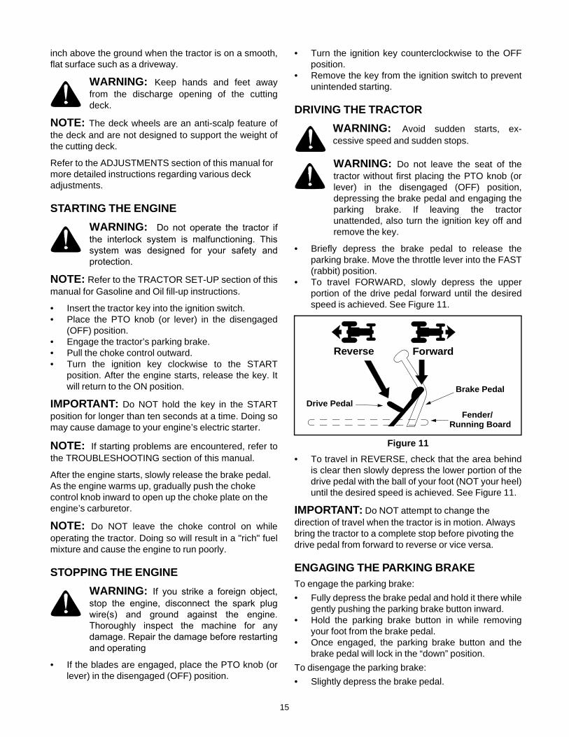
DRIVING THE TRACTOR
WARNING: Avoid sudden starts, ex-cessive speed and sudden stops.
WARNING: Do not leave the seat of thetractor without first placing the PTO knob (orlever) in the disengaged (OFF) position,depressing the brake pedal and engaging theparking brake. If leaving the tractorunattended, also turn the ignition key off andremove the key.
• Briefly depress the brake pedal to release theparking brake. Move the throttle lever into the FAST(rabbit) position.
• To travel FORWARD, slowly depress the upperportion of the drive pedal forward until the desiredspeed is achieved. See Figure 11.
Figure 11
• To travel in REVERSE, check that the area behindis clear then slowly depress the lower portion of thedrive pedal with the ball of your foot (NOT your heel)until the desired speed is achieved. See Figure 11.
IMPORTANT: Do NOT attempt to change the direction of travel when the tractor is in motion. Always bring the tractor to a complete stop before pivoting the drive pedal from forward to reverse or vice versa.
ENGAGING THE PARKING BRAKETo engage the parking brake:
• Fully depress the brake pedal and hold it there whilegently pushing the parking brake button inward.
• Hold the parking brake button in while removingyour foot from the brake pedal.
• Once engaged, the parking brake button and thebrake pedal will lock in the “down” position.
To disengage the parking brake:
• Slightly depress the brake pedal.
Reverse Forward
Drive PedalFender/
Brake Pedal
Running Board
16
NOTE: The parking brake must be engaged if theoperator leaves the seat with the engine running or theengine will automatically shut off.
DRIVING ON SLOPESRefer to the SLOPE GAUGE on page 7 to help determine slopes where you may not operate safely.
WARNING: Do not mow on inclines with aslope in excess of 15 degrees (a rise ofapproximately 2-1/2 feet every 10 feet). Thetractor could overturn and cause seriousinjury.
• Mow up and down slopes, NEVER across.• Exercise extreme caution when changing direction
on slopes.• Watch for holes, ruts, bumps, rocks, or other hidden
objects. Uneven terrain could overturn the machine.Tall grass can hide obstacles.
• Avoid turns when driving on a slope. If a turn mustbe made, turn down the slope. Turning up a slopegreatly increases the chance of a roll over.
• Avoid stopping when driving up a slope. If it isnecessary to stop while driving up a slope, start upsmoothly and carefully to reduce the possibility offlipping the tractor over backward.
SETTING THE CRUISE CONTROL
NOTE: The cruise control feature should only beutilized while traveling in the forward direction.
• Slowly depress the upper portion of the drive pedaluntil the desired speed is achieved.
• Lightly depress the cruise control button.• While continuing to hold the cruise button in, lift
your foot from the drive pedal (you should feel thecruise latch engage).
• Once engaged, the cruise control button and thedrive pedal will lock in the “down” position, and thetractor will maintain the same forward speed.
NOTE: Cruise control can not be engaged at thetractor’s fastest ground speed. If the operator shouldattempt to do so, the tractor will automaticallydecelerate to the fastest optimal mowing ground speed.
Disengage the cruise control using one of the followingmethods:
• Depress the brake pedal to disengage the cruisecontrol and stop the tractor.
• Lightly depress the drive pedal.To change the direction of travel to reverse whenoperating with cruise control, depress the brake pedalto disengage the cruise control and bring the tractor to acomplete stop. Then slowly depress the lower portion ofthe drive pedal with the ball of your foot to travel inreverse.
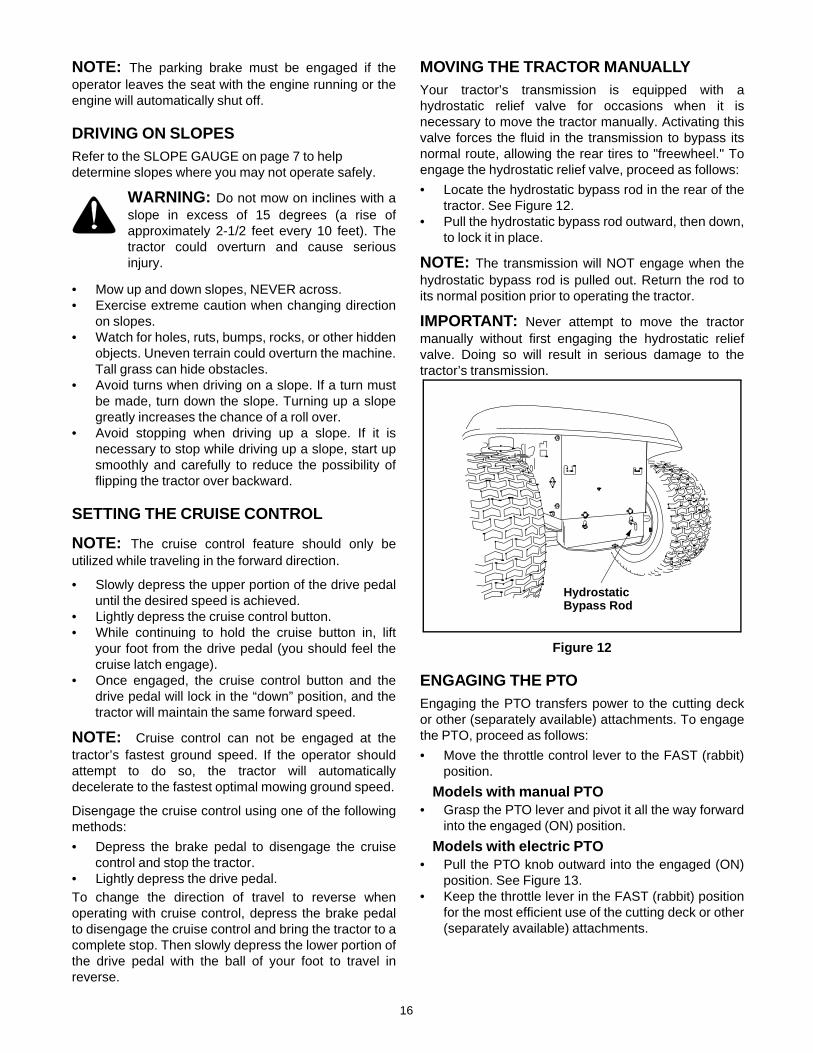
MOVING THE TRACTOR MANUALLYYour tractor’s transmission is equipped with ahydrostatic relief valve for occasions when it isnecessary to move the tractor manually. Activating thisvalve forces the fluid in the transmission to bypass itsnormal route, allowing the rear tires to "freewheel." Toengage the hydrostatic relief valve, proceed as follows:
• Locate the hydrostatic bypass rod in the rear of thetractor. See Figure 12.
• Pull the hydrostatic bypass rod outward, then down,to lock it in place.
NOTE: The transmission will NOT engage when thehydrostatic bypass rod is pulled out. Return the rod toits normal position prior to operating the tractor.
IMPORTANT: Never attempt to move the tractormanually without first engaging the hydrostatic reliefvalve. Doing so will result in serious damage to thetractor’s transmission.
Figure 12
ENGAGING THE PTOEngaging the PTO transfers power to the cutting deckor other (separately available) attachments. To engagethe PTO, proceed as follows:
• Move the throttle control lever to the FAST (rabbit)position.
Models with manual PTO• Grasp the PTO lever and pivot it all the way forward
into the engaged (ON) position.
Models with electric PTO• Pull the PTO knob outward into the engaged (ON)
position. See Figure 13.• Keep the throttle lever in the FAST (rabbit) position
for the most efficient use of the cutting deck or other(separately available) attachments.
HydrostaticBypass Rod
17
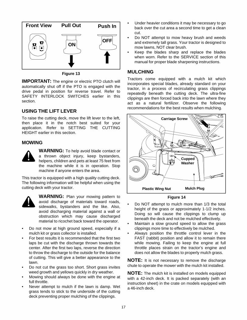
Figure 13
IMPORTANT: The engine or electric PTO clutch willautomatically shut off if the PTO is engaged with thedrive pedal in position for reverse travel. Refer toSAFETY INTERLOCK SWITCHES earlier in thissection.
USING THE LIFT LEVERTo raise the cutting deck, move the lift lever to the left,then place it in the notch best suited for yourapplication. Refer to SETTING THE CUTTINGHEIGHT earlier in this section.
MOWING
WARNING: To help avoid blade contact ora thrown object injury, keep bystanders,helpers, children and pets at least 75 feet fromthe machine while it is in operation. Stopmachine if anyone enters the area.
This tractor is equipped with a high quality cutting deck.The following information will be helpful when using thecutting deck with your tractor.
WARNING: Plan your mowing pattern toavoid discharge of materials toward roads,sidewalks, bystanders and the like. Also,avoid discharging material against a wall orobstruction which may cause dischargedmaterial to ricochet back toward the operator.
• Do not mow at high ground speed, especially if amulch kit or grass collector is installed.
• For best results it is recommended that the first twolaps be cut with the discharge thrown towards thecenter. After the first two laps, reverse the directionto throw the discharge to the outside for the balanceof cutting. This will give a better appearance to thelawn.
• Do not cut the grass too short. Short grass invitesweed growth and yellows quickly in dry weather.
• Mowing should always be done with the engine atfull throttle.
• Never attempt to mulch if the lawn is damp. Wetgrass tends to stick to the underside of the cuttingdeck preventing proper mulching of the clippings.
• Under heavier conditions it may be necessary to goback over the cut area a second time to get a cleancut.
• Do NOT attempt to mow heavy brush and weedsand extremely tall grass. Your tractor is designed tomow lawns, NOT clear brush.
• Keep the blades sharp and replace the bladeswhen worn. Refer to the SERVICE section of thismanual for proper blade sharpening instructions.
MULCHINGTractors come equipped with a mulch kit whichincorporates special blades, already standard on yourtractor, in a process of recirculating grass clippingsrepeatedly beneath the cutting deck. The ultra-fineclippings are then forced back into the lawn where theyact as a natural fertilizer. Observe the followingrecommendations for the best results when mulching.
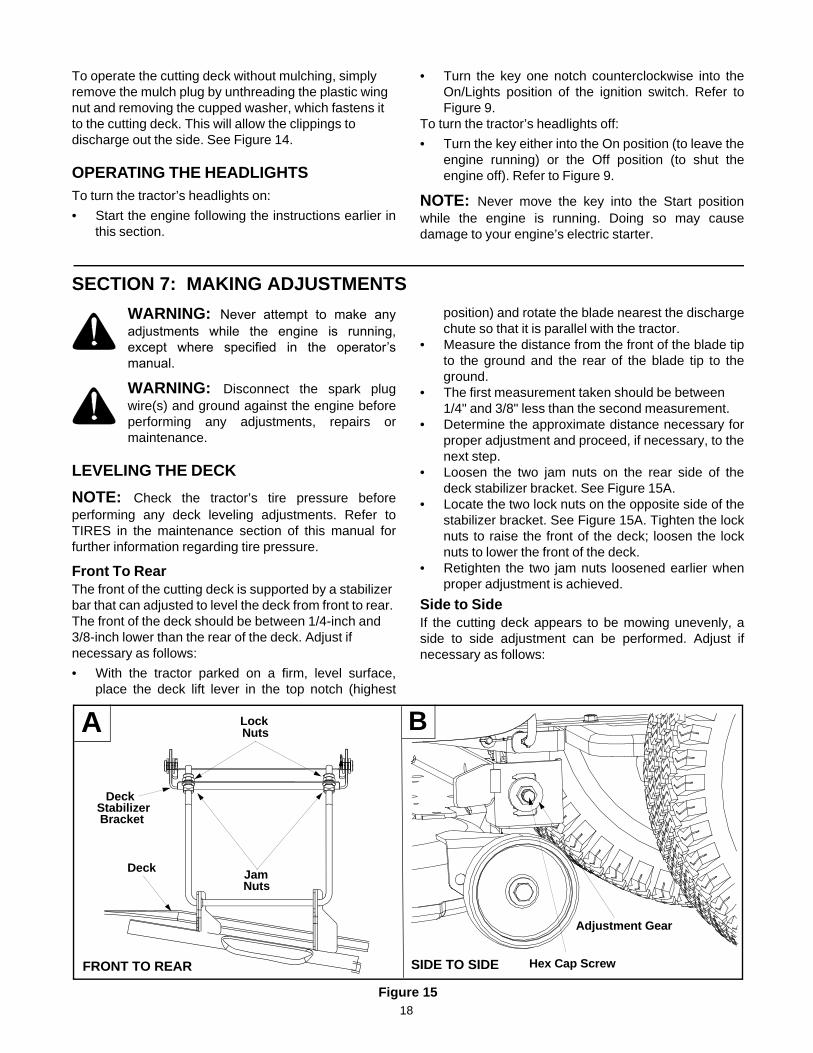
Figure 14
• Do NOT attempt to mulch more than 1/3 the totalheight of the grass or approximately 1-1/2 inches.Doing so will cause the clippings to clump upbeneath the deck and not be mulched effectively.
• Maintain a slow ground speed to allow the grassclippings more time to effectively be mulched.
• Always position the throttle control lever in theFAST (rabbit) position and allow it to remain therewhile mowing. Failing to keep the engine at fullthrottle places strain on the tractor’s engine anddoes not allow the blades to properly mulch grass.
NOTE: It is not necessary to remove the dischargechute to operate the mower with the mulch kit installed.
NOTE: The mulch kit is installed on models equippedwith a 42-inch deck. It is packed separately (with aninstruction sheet) in the crate on models equipped witha 46-inch deck.
ONOFF
Front View Pull Out Push In
Carriage Screw
Plastic Wing Nut
Cupped
Mulch Plug
Washer
18
To operate the cutting deck without mulching, simply remove the mulch plug by unthreading the plastic wing nut and removing the cupped washer, which fastens it to the cutting deck. This will allow the clippings to discharge out the side. See Figure 14.
OPERATING THE HEADLIGHTSTo turn the tractor’s headlights on:
• Start the engine following the instructions earlier inthis section.
• Turn the key one notch counterclockwise into theOn/Lights position of the ignition switch. Refer toFigure 9.
To turn the tractor’s headlights off:
• Turn the key either into the On position (to leave theengine running) or the Off position (to shut theengine off). Refer to Figure 9.
NOTE: Never move the key into the Start positionwhile the engine is running. Doing so may causedamage to your engine’s electric starter.
SECTION 7: MAKING ADJUSTMENTS
WARNING: Never attempt to make anyadjustments while the engine is running,except where specified in the operator’smanual.
WARNING: Disconnect the spark plugwire(s) and ground against the engine beforeperforming any adjustments, repairs ormaintenance.
LEVELING THE DECK
NOTE: Check the tractor’s tire pressure beforeperforming any deck leveling adjustments. Refer toTIRES in the maintenance section of this manual forfurther information regarding tire pressure.
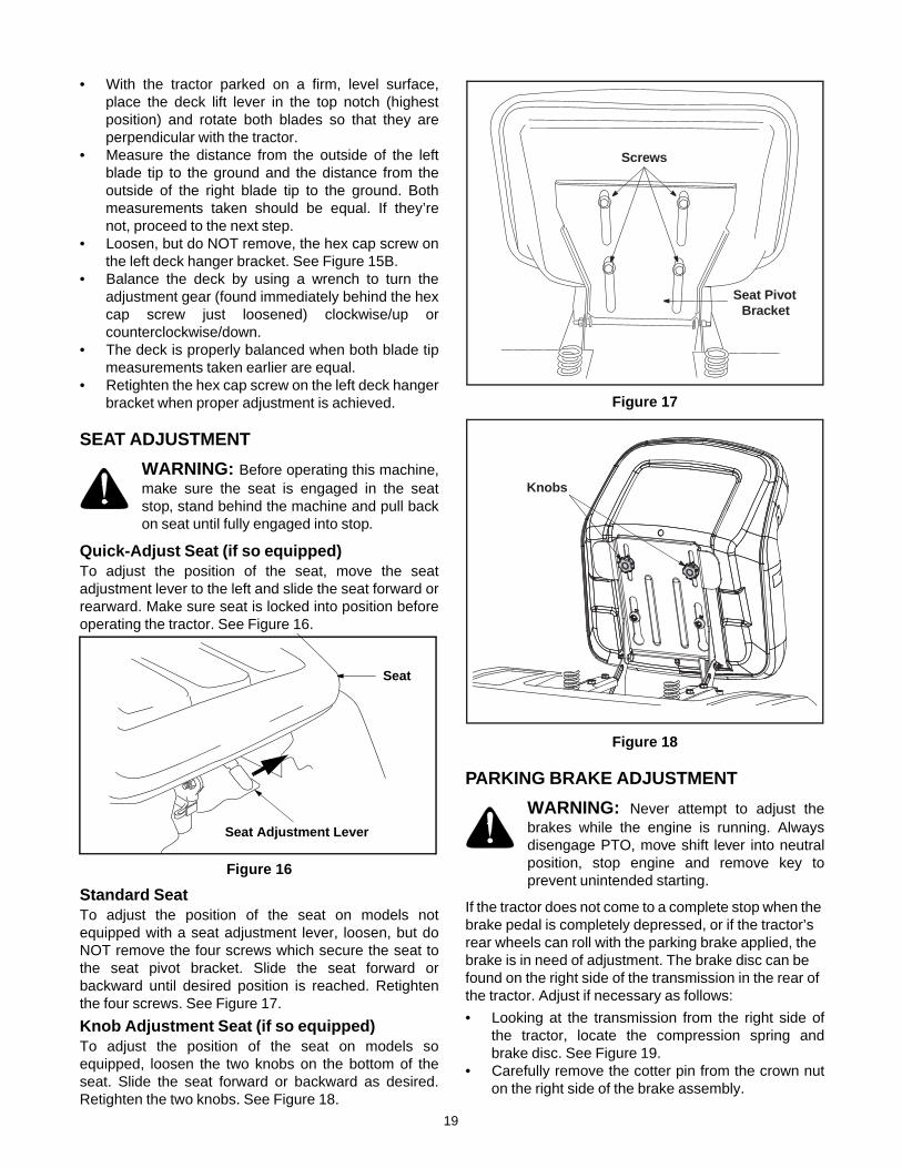
Front To RearThe front of the cutting deck is supported by a stabilizer bar that can adjusted to level the deck from front to rear. The front of the deck should be between 1/4-inch and 3/8-inch lower than the rear of the deck. Adjust if necessary as follows:
• With the tractor parked on a firm, level surface,place the deck lift lever in the top notch (highest
position) and rotate the blade nearest the dischargechute so that it is parallel with the tractor.
• Measure the distance from the front of the blade tipto the ground and the rear of the blade tip to theground.
• The first measurement taken should be between 1/4" and 3/8" less than the second measurement.
• Determine the approximate distance necessary forproper adjustment and proceed, if necessary, to thenext step.
• Loosen the two jam nuts on the rear side of thedeck stabilizer bracket. See Figure 15A.
• Locate the two lock nuts on the opposite side of thestabilizer bracket. See Figure 15A. Tighten the locknuts to raise the front of the deck; loosen the locknuts to lower the front of the deck.
• Retighten the two jam nuts loosened earlier whenproper adjustment is achieved.
Side to SideIf the cutting deck appears to be mowing unevenly, aside to side adjustment can be performed. Adjust ifnecessary as follows:
Figure 15
Jam
DeckStabilizerBracket
Nuts
Lock Nuts
Deck
A B
FRONT TO REAR SIDE TO SIDE Hex Cap Screw
Adjustment Gear
19
• With the tractor parked on a firm, level surface,place the deck lift lever in the top notch (highestposition) and rotate both blades so that they areperpendicular with the tractor.
• Measure the distance from the outside of the leftblade tip to the ground and the distance from theoutside of the right blade tip to the ground. Bothmeasurements taken should be equal. If they’renot, proceed to the next step.
• Loosen, but do NOT remove, the hex cap screw onthe left deck hanger bracket. See Figure 15B.
• Balance the deck by using a wrench to turn theadjustment gear (found immediately behind the hexcap screw just loosened) clockwise/up orcounterclockwise/down.
• The deck is properly balanced when both blade tipmeasurements taken earlier are equal.
• Retighten the hex cap screw on the left deck hangerbracket when proper adjustment is achieved.
SEAT ADJUSTMENT
WARNING: Before operating this machine,make sure the seat is engaged in the seatstop, stand behind the machine and pull backon seat until fully engaged into stop.
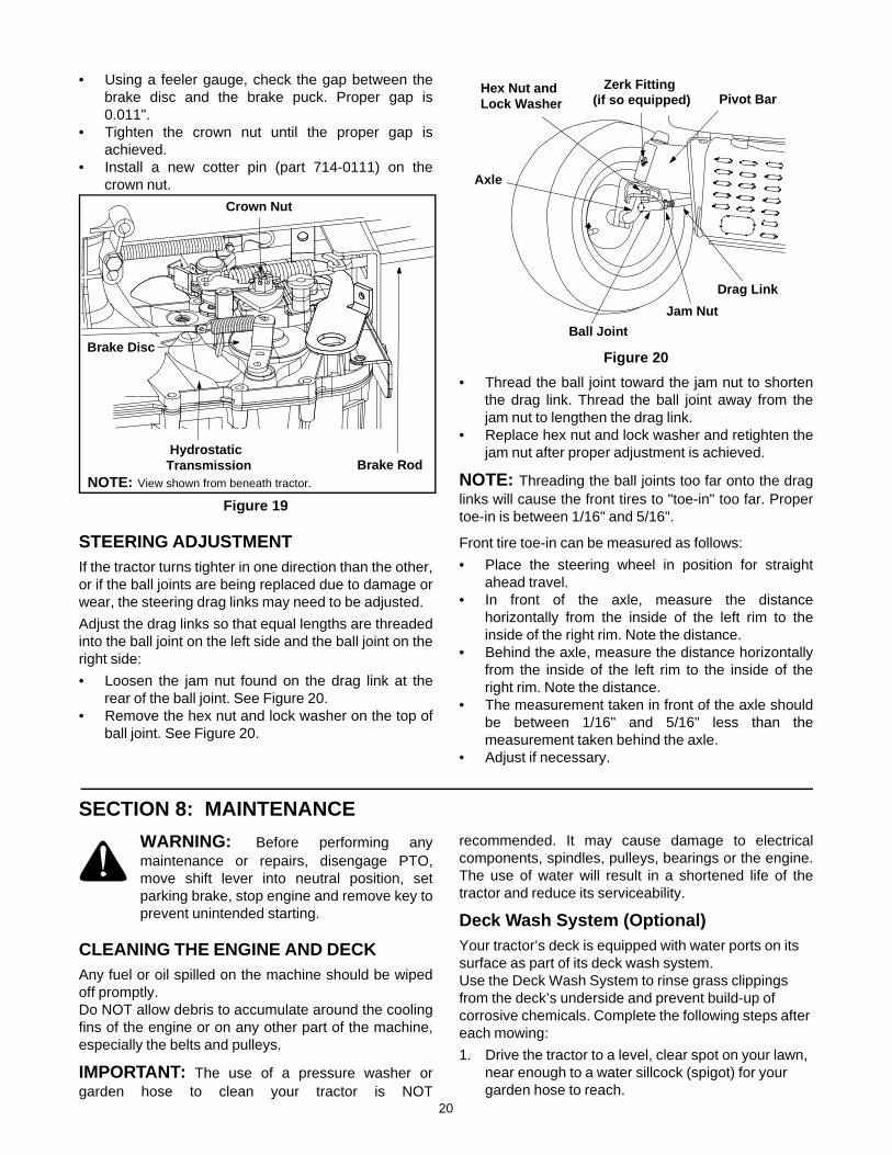
Quick-Adjust Seat (if so equipped)To adjust the position of the seat, move the seatadjustment lever to the left and slide the seat forward orrearward. Make sure seat is locked into position beforeoperating the tractor. See Figure 16.
Figure 16
Standard Seat To adjust the position of the seat on models notequipped with a seat adjustment lever, loosen, but doNOT remove the four screws which secure the seat tothe seat pivot bracket. Slide the seat forward orbackward until desired position is reached. Retightenthe four screws. See Figure 17.
Knob Adjustment Seat (if so equipped)To adjust the position of the seat on models soequipped, loosen the two knobs on the bottom of theseat. Slide the seat forward or backward as desired.Retighten the two knobs. See Figure 18.
Figure 17
Figure 18
PARKING BRAKE ADJUSTMENT
WARNING: Never attempt to adjust thebrakes while the engine is running. Alwaysdisengage PTO, move shift lever into neutralposition, stop engine and remove key toprevent unintended starting.
If the tractor does not come to a complete stop when the brake pedal is completely depressed, or if the tractor’s rear wheels can roll with the parking brake applied, the brake is in need of adjustment. The brake disc can be found on the right side of the transmission in the rear of the tractor. Adjust if necessary as follows:
• Looking at the transmission from the right side ofthe tractor, locate the compression spring andbrake disc. See Figure 19.
• Carefully remove the cotter pin from the crown nuton the right side of the brake assembly.
Seat
Seat Adjustment Lever
Screws
Seat PivotBracket
Knobs
20
• Using a feeler gauge, check the gap between thebrake disc and the brake puck. Proper gap is0.011".
• Tighten the crown nut until the proper gap isachieved.
• Install a new cotter pin (part 714-0111) on thecrown nut.
Figure 19
STEERING ADJUSTMENTIf the tractor turns tighter in one direction than the other,or if the ball joints are being replaced due to damage orwear, the steering drag links may need to be adjusted.
Adjust the drag links so that equal lengths are threadedinto the ball joint on the left side and the ball joint on theright side:
• Loosen the jam nut found on the drag link at therear of the ball joint. See Figure 20.
• Remove the hex nut and lock washer on the top ofball joint. See Figure 20.
Figure 20
• Thread the ball joint toward the jam nut to shortenthe drag link. Thread the ball joint away from thejam nut to lengthen the drag link.
• Replace hex nut and lock washer and retighten thejam nut after proper adjustment is achieved.
NOTE: Threading the ball joints too far onto the draglinks will cause the front tires to "toe-in" too far. Propertoe-in is between 1/16" and 5/16".
Front tire toe-in can be measured as follows:
• Place the steering wheel in position for straightahead travel.
• In front of the axle, measure the distancehorizontally from the inside of the left rim to theinside of the right rim. Note the distance.
• Behind the axle, measure the distance horizontallyfrom the inside of the left rim to the inside of theright rim. Note the distance.
• The measurement taken in front of the axle shouldbe between 1/16" and 5/16" less than themeasurement taken behind the axle.
• Adjust if necessary.
SECTION 8: MAINTENANCE
WARNING: Before performing anymaintenance or repairs, disengage PTO,move shift lever into neutral position, setparking brake, stop engine and remove key toprevent unintended starting.
CLEANING THE ENGINE AND DECKAny fuel or oil spilled on the machine should be wipedoff promptly. Do NOT allow debris to accumulate around the coolingfins of the engine or on any other part of the machine,especially the belts and pulleys.
IMPORTANT: The use of a pressure washer orgarden hose to clean your tractor is NOT
recommended. It may cause damage to electricalcomponents, spindles, pulleys, bearings or the engine.The use of water will result in a shortened life of thetractor and reduce its serviceability.
Deck Wash System (Optional)Your tractor’s deck is equipped with water ports on its surface as part of its deck wash system. Use the Deck Wash System to rinse grass clippings from the deck’s underside and prevent build-up of corrosive chemicals. Complete the following steps after each mowing:
1. Drive the tractor to a level, clear spot on your lawn, near enough to a water sillcock (spigot) for your garden hose to reach.
Brake Disc
Crown Nut
NOTE: View shown from beneath tractor.
Hydrostatic Transmission Brake Rod
Drag Link
Ball Joint
Axle
Pivot BarHex Nut and
Jam Nut
Lock WasherZerk Fitting
(if so equipped)
21
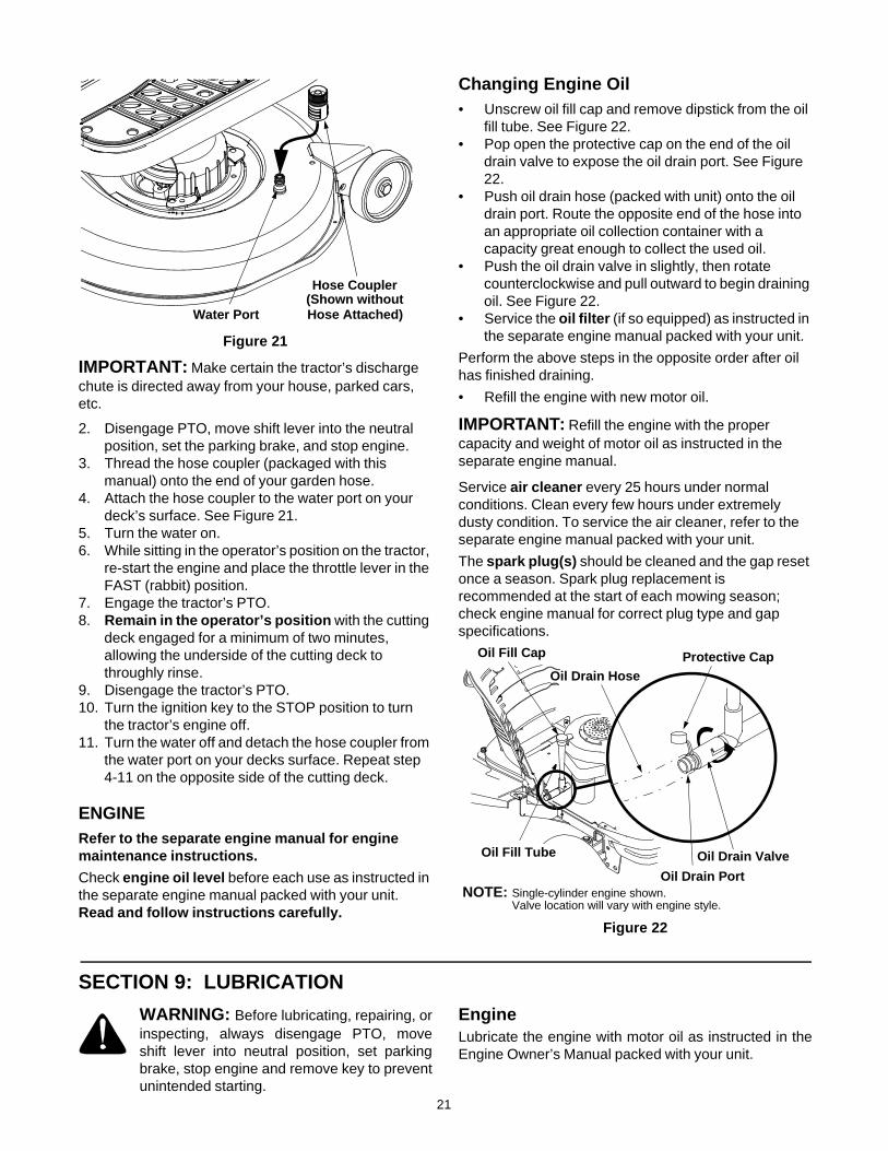
Figure 21
IMPORTANT: Make certain the tractor’s discharge chute is directed away from your house, parked cars, etc.
2. Disengage PTO, move shift lever into the neutral position, set the parking brake, and stop engine.
3. Thread the hose coupler (packaged with this manual) onto the end of your garden hose.
4. Attach the hose coupler to the water port on your deck’s surface. See Figure 21.
5. Turn the water on.6. While sitting in the operator’s position on the tractor,
re-start the engine and place the throttle lever in the FAST (rabbit) position.
7. Engage the tractor’s PTO.8. Remain in the operator’s position with the cutting
deck engaged for a minimum of two minutes, allowing the underside of the cutting deck to throughly rinse.
9. Disengage the tractor’s PTO.10. Turn the ignition key to the STOP position to turn
the tractor’s engine off.11. Turn the water off and detach the hose coupler from
the water port on your decks surface. Repeat step 4-11 on the opposite side of the cutting deck.
ENGINE Refer to the separate engine manual for engine maintenance instructions.
Check engine oil level before each use as instructed in the separate engine manual packed with your unit. Read and follow instructions carefully.
Changing Engine Oil• Unscrew oil fill cap and remove dipstick from the oil
fill tube. See Figure 22.• Pop open the protective cap on the end of the oil
drain valve to expose the oil drain port. See Figure 22.
• Push oil drain hose (packed with unit) onto the oil drain port. Route the opposite end of the hose into an appropriate oil collection container with a capacity great enough to collect the used oil.
• Push the oil drain valve in slightly, then rotate counterclockwise and pull outward to begin draining oil. See Figure 22.
• Service the oil filter (if so equipped) as instructed in the separate engine manual packed with your unit.
Perform the above steps in the opposite order after oil has finished draining.
• Refill the engine with new motor oil.
IMPORTANT: Refill the engine with the proper capacity and weight of motor oil as instructed in the separate engine manual.
Service air cleaner every 25 hours under normal conditions. Clean every few hours under extremely dusty condition. To service the air cleaner, refer to the separate engine manual packed with your unit.
The spark plug(s) should be cleaned and the gap reset once a season. Spark plug replacement is recommended at the start of each mowing season; check engine manual for correct plug type and gap specifications.
Figure 22
SECTION 9: LUBRICATION
WARNING: Before lubricating, repairing, orinspecting, always disengage PTO, moveshift lever into neutral position, set parkingbrake, stop engine and remove key to preventunintended starting.
EngineLubricate the engine with motor oil as instructed in theEngine Owner’s Manual packed with your unit.
Water Port
Hose Coupler(Shown withoutHose Attached)
Protective CapOil Drain Hose
Oil Drain Port
Oil Fill Cap
Oil Fill Tube Oil Drain Valve
Single-cylinder engine shown.NOTE:Valve location will vary with engine style.
22
Pivot Points & LinkageLubricate all the pivot points on the drive system,parking brake and lift linkage at least once a seasonwith light oil.
TransmissionThe hydrostatic transmission is sealed at the factory.Oil level cannot be checked nor can the oil be changed.
Front WheelsEach of the front wheel axles is equipped with a greasefitting. Lubricate with a grease gun after every 25 hoursof tractor operation.
Rear WheelsThe rear wheels should be removed from the axlesonce a season. Lubricate the axles and the rims wellwith an all-purpose grease before re-installing them.
SECTION 10: SERVICE
TIRES
WARNING: Never exceed the maximuminflation pressure shown on the sidewall of thetire.
The recommended operating tire pressure is 10 psi forthe rear tires and 14 psi for the front tires. Refer to thetire sidewall for exact tire manufacturer’s recommendedor maximum psi. Do not overinflate. Uneven tirepressure could cause the cutting deck to mowunevenly.
CUTTING BLADES
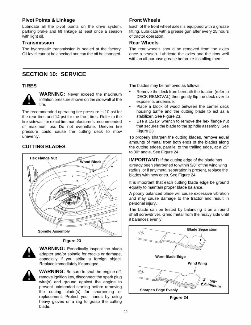
Figure 23
WARNING: Periodically inspect the bladeadapter and/or spindle for cracks or damage,especially if you strike a foreign object.Replace immediately if damaged.
WARNING: Be sure to shut the engine off,remove ignition key, disconnect the spark plugwire(s) and ground against the engine toprevent unintended starting before removingthe cutting blade(s) for sharpening orreplacement. Protect your hands by usingheavy gloves or a rag to grasp the cuttingblade.
The blades may be removed as follows.
• Remove the deck from beneath the tractor, (refer toDECK REMOVAL) then gently flip the deck over toexpose its underside.
• Place a block of wood between the center deckhousing baffle and the cutting blade to act as astabilizer. See Figure 23.
• Use a 15/16" wrench to remove the hex flange nutthat secures the blade to the spindle assembly. SeeFigure 23.
To properly sharpen the cutting blades, remove equalamounts of metal from both ends of the blades alongthe cutting edges, parallel to the trailing edge, at a 25°to 30° angle. See Figure 24 .
IMPORTANT: If the cutting edge of the blade has already been sharpened to within 5/8" of the wind wing radius, or if any metal separation is present, replace the blades with new ones. See Figure 24.
It is important that each cutting blade edge be groundequally to maintain proper blade balance.
A poorly balanced blade will cause excessive vibrationand may cause damage to the tractor and result inpersonal injury.
The blade can be tested by balancing it on a roundshaft screwdriver. Grind metal from the heavy side untilit balances evenly.
Figure 24
Spindle Assembly
Hex Flange NutWood Block
Blade Separation
Worn Blade Edge
Wind Wing
Sharpen Edge Evenly
5/8"minimum

23
When replacing the blade, be sure to install the bladewith the side of the blade marked ‘‘Bottom’’ (or with apart number stamped in it) facing the ground when themower is in the operating position.
BATTERYThe battery is sealed and is maintenance-free. Acidlevels cannot be checked.
WARNING: Shield eyes (e.g. goggles, faceshield) and protect skin and clothing whenhandling battery acid or a battery containingacid.
• Always keep the battery cables and terminals cleanand free of corrosive build-up.
• After cleaning the battery and terminals, apply alight coat of petroleum jelly or grease to bothterminals
• Always keep the rubber boot positioned over thepositive terminal to prevent shorting.
IMPORTANT: If removing the battery for any reason,disconnect the NEGATIVE (Black) wire from it’sterminal first, followed by the POSITIVE (Red) wire.When re-installing the battery, always connect thePOSITIVE (Red) wire its terminal first, followed by theNEGATIVE (Black) wire. Be certain that the wires areconnected to the correct terminals; reversing themcould change the polarity and cause damage to yourengine’s alternating system.
IMPORTANT:
1. Battery wires must be connected to the correct terminals. Reversing them could change the polarity and damage engine’s alternating system.
2. Do not jump-start a damaged battery.3. When storing the battery, disconnect the negative
terminal and store with full charge.
ChargingIf the unit has not been put into use for an extendedperiod of time, charge the battery with an automotive-type 12-volt charger for a minimum of one hour at sixamps.
WARNING: Batteries give off an explosivegas while charging. Charge battery in a wellventilated area and keep away from an openflame or pilot light as on a water heater, spaceheater, furnace, clothes dryer or other gasappliances.
JUMP STARTING
WARNING: When removing or installingthe battery, follow these instructions toprevent the screwdriver from shorting againstthe frame.
IMPORTANT: Never jump your tractor’s dead battery with the battery of a running vehicle.
• Connect end of one jumper cable to the positiveterminal of the good battery, then the other end tothe positive terminal of the dead battery.
• Connect the other jumper cable to the negativeterminal of the good battery, then to the frame of theunit with the dead battery.
WARNING: Failure to use this procedurecould cause sparking, and the gas in eitherbattery could explode.
WARNING: Do not use the tractor batteryto start other vehicles.
Cleaning the batteryKeep the terminals and the top of the battery clean andfree from corrosion. Clean the battery with baking sodaor a commercial battery cleaner. If necessary, scrapethe battery terminals with a wire brush to removedeposits. Coat terminals and exposed wiring withgrease or petroleum jelly to prevent corrosion.
CAUTION: Do not allow any cleaning solution to getinside the battery.
Battery failuresSome common causes for battery failure are:
• incorrect initial activation• undercharging• overcharging• corroded connections• freezing
These failures are NOT covered by your tractor’s warranty.
FUSESTwo fuses are installed in your tractor’s wiring harnessto protect the tractor’s electrical system from damagecaused by excessive amperage.
If the electrical system does not function, or yourtractor’s engine will not crank, first check to be certainthat the fuse has not blown. See Figure 25.
Figure 25
One can be found under the hood mounted behind thetop of the dash panel on the support bar. The other can be found under the seat mounted to theinside of the tractor frame next to the battery tray. Pullthe fuse out and inspect it to determine if it is good orblown.
GOOD BAD
24
WARNING: Always use a fuse with thesame amperage capacity for replacement.
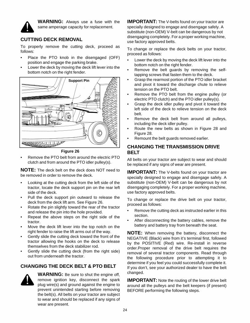
CUTTING DECK REMOVALTo properly remove the cutting deck, proceed asfollows:
• Place the PTO knob in the disengaged (OFF)position and engage the parking brake.
• Lower the deck by moving the deck lift lever into thebottom notch on the right fender.
Figure 26
• Remove the PTO belt from around the electric PTOclutch and from around the PTO idler pulley(s).
NOTE: The deck belt on the deck does NOT need tobe removed in order to remove the deck.
• Looking at the cutting deck from the left side of thetractor, locate the deck support pin on the rear leftside of the deck.
• Pull the deck support pin outward to release thedeck from the deck lift arm. See Figure 26.
• Rotate the pin slightly toward the rear of the tractorand release the pin into the hole provided.
• Repeat the above steps on the right side of thetractor.
• Move the deck lift lever into the top notch on theright fender to raise the lift arms out of the way.
• Gently slide the cutting deck toward the front of thetractor allowing the hooks on the deck to releasethemselves from the deck stabilizer rod.
• Gently slide the cutting deck (from the right side)out from underneath the tractor.
CHANGING THE DECK BELT & PTO BELT
WARNING: Be sure to shut the engine off,remove ignition key, disconnect the sparkplug wire(s) and ground against the engine toprevent unintended starting before removingthe belt(s). All belts on your tractor are subjectto wear and should be replaced if any signs ofwear are present.
IMPORTANT: The V-belts found on your tractor are specially designed to engage and disengage safely. A substitute (non-OEM) V-belt can be dangerous by not disengaging completely. For a proper working machine, use factory approved belts.
To change or replace the deck belts on your tractor,proceed as follows:
• Lower the deck by moving the deck lift lever into thebottom notch on the right fender.
• Remove the belt guards by removing the self-tapping screws that fasten them to the deck.
• Grasp the rearmost portion of the PTO idler bracketand pivot it toward the discharge chute to relievetension on the PTO belt.
• Remove the PTO belt from the engine pulley (orelectric PTO clutch) and the PTO idler pulley(s).
• Grasp the deck idler pulley and pivot it toward theleft side of the deck to relieve tension on the deckbelt.
• Remove the deck belt from around all pulleys,including the deck idler pulley.
• Route the new belts as shown in Figure 28 andFigure 28.
• Remount the belt guards removed earlier.
CHANGING THE TRANSMISSION DRIVE BELTAll belts on your tractor are subject to wear and shouldbe replaced if any signs of wear are present.
IMPORTANT: The V-belts found on your tractor arespecially designed to engage and disengage safely. Asubstitute (non-OEM) V-belt can be dangerous by notdisengaging completely. For a proper working machine,use factory approved belts.
To change or replace the drive belt on your tractor,proceed as follows:
• Remove the cutting deck as instructed earlier in thissection.
• After disconnecting the battery cables, remove thebattery and battery tray from beneath the seat.
NOTE: When removing the battery, disconnect theNEGATIVE (Black) wire from it’s terminal first, followedby the POSITIVE (Red) wire. Re-install in reverseorder.Proper removal of the drive belt requires theremoval of several tractor components. Read throughthe following procedure prior to attempting it todetermine if you feel you could successfully complete it.If you don’t, see your authorized dealer to have the beltchanged.
IMPORTANT: Note the routing of the lower drive beltaround all the pulleys and the belt keepers (if present)BEFORE performing the following steps.
Support Pin
25
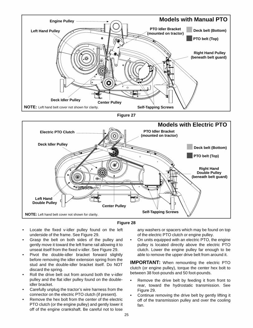
Figure 27
Figure 28
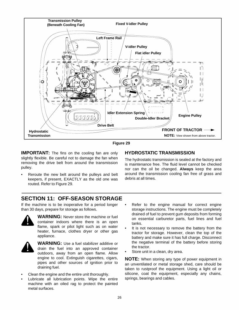
• Locate the fixed v-idler pulley found on the leftunderside of the frame. See Figure 29.
• Grasp the belt on both sides of the pulley andgently move it toward the left frame rail allowing it tounseat itself from the fixed v-idler. See Figure 29.
• Pivot the double-idler bracket forward slightlybefore removing the idler extension spring from thestud and the double-idler bracket itself. Do NOTdiscard the spring.
• Roll the drive belt out from around both the v-idlerpulley and the flat idler pulley found on the double-idler bracket.
• Carefully unplug the tractor’s wire harness from theconnector on the electric PTO clutch (if present).
• Remove the hex bolt from the center of the electricPTO clutch (or the engine pulley) and gently lower itoff of the engine crankshaft. Be careful not to lose
any washers or spacers which may be found on topof the electric PTO clutch or engine pulley.
• On units equipped with an electric PTO, the enginepulley is located directly above the electric PTOclutch. Lower the engine pulley far enough to beable to remove the upper drive belt from around it.
IMPORTANT: When remounting the electric PTOclutch (or engine pulley), torque the center hex bolt tobetween 38 foot-pounds and 50 foot-pounds.
• Remove the drive belt by feeding it from front torear, toward the hydrostatic transmission. SeeFigure 29.
• Continue removing the drive belt by gently lifting itoff of the transmission pulley and over the coolingfan.
Engine Pulley
PTO Idler BracketLeft Hand Pulley
Right Hand Pulley(beneath belt guard)
Center PulleyDeck Idler Pulley
Self-Tapping Screws
(mounted on tractor)
NOTE: Left hand belt cover not shown for clarity.
Models with Manual PTO
Deck belt (Bottom)
PTO belt (Top)
Electric PTO Clutch
Left HandDouble Pulley
Right HandDouble Pulley
Center Pulley
Deck Idler Pulley
Self-Tapping Screws
(beneath belt guard)
PTO Idler Bracket(mounted on tractor)
NOTE: Left hand belt cover not shown for clarity.
Deck belt (Bottom)
PTO belt (Top)
Models with Electric PTO
26
Figure 29
IMPORTANT: The fins on the cooling fan are onlyslightly flexible. Be careful not to damage the fan whenremoving the drive belt from around the transmissionpulley.
• Reroute the new belt around the pulleys and beltkeepers, if present, EXACTLY as the old one wasrouted. Refer to Figure 29.
HYDROSTATIC TRANSMISSIONThe hydrostatic transmission is sealed at the factory andis maintenance free. The fluid level cannot be checkednor can the oil be changed. Always keep the areaaround the transmission cooling fan free of grass anddebris at all times.
SECTION 11: OFF-SEASON STORAGEIf the machine is to be inoperative for a period longerthan 30 days, prepare for storage as follows.
WARNING: Never store the machine or fuelcontainer indoors where there is an openflame, spark or pilot light such as on waterheater, furnace, clothes dryer or other gasappliance.
WARNING: Use a fuel stabilizer additive ordrain the fuel into an approved containeroutdoors, away from an open flame. Allowengine to cool. Extinguish cigarettes, cigars,pipes and other sources of ignition prior todraining fuel.
• Clean the engine and the entire unit thoroughly. • Lubricate all lubrication points. Wipe the entire
machine with an oiled rag to protect the paintedmetal surfaces.
• Refer to the engine manual for correct enginestorage instructions. The engine must be completelydrained of fuel to prevent gum deposits from formingon essential carburetor parts, fuel lines and fueltanks.
• It is not necessary to remove the battery from thetractor for storage. However, clean the top of thebattery and make sure it has full charge. Disconnectthe negative terminal of the battery before storingthe tractor.
• Store unit in a clean, dry area.
NOTE: When storing any type of power equipment inan unventilated or metal storage shed, care should betaken to rustproof the equipment. Using a light oil orsilicone, coat the equipment, especially any chains,springs, bearings and cables.
FRONT OF TRACTOR
Fixed V-idler PulleyTransmission Pulley
Engine Pulley
Hydrostatic
Double-Idler Bracket
V-idler Pulley
NOTE: View shown from above tractor.
Idler Extension Spring
Drive Belt
Left Frame Rail
Flat idler Pulley
(Beneath Cooling Fan)
Transmission

27
SECTION 12: TROUBLESHOOTING
Trouble Possible Cause(s) Corrective Action
Engine fails to start PTO lever engaged.Parking brake not engaged.Spark plug wire(s) disconnected.Throttle control not in correct positionChoke not activatedFuel tank empty, or stale fuel.Blocked fuel line.Faulty spark plug.Engine flooded.
Place PTO lever in disengaged (OFF) position.Engage parking brake.Connect wire(s) to spark plug.Place throttle lever to fast or choke (if so equipped).Activate choke.Fill tank with clean, fresh (less than 30 days old) gas.Clean fuel line or replace fuel filter, if so equipped.Clean, adjust gap or replace plug.Crank engine with throttle in FAST position.
Engine runs erratic Unit running with CHOKE applied.Spark plug wire loose.Blocked fuel line or stale fuel.
Vent in gas cap plugged.Water or dirt in fuel system.
Dirty air cleaner.
Place throttle lever in FAST position.Connect and tighten spark plug wire.Clean fuel line; fill tank with clean, fresh (less than 30 days old) gasoline. Replace fuel filter, if so equipped.Clear vent or replace cap if damaged.Drain fuel tank. Refill with clean, fresh (less than 30 days old) gasoline.Replace air cleaner cartridge/element or clean pre-cleaner, if so equipped.
Engine overheats Engine oil level low.Air flow restricted.
Fill crankcase with proper capacity and weight of oil.Clean grass clippings and debris from around the engine’s cooling fins and blower housing.
Engine hesitates at high RPM
Spark plug gap too close. Remove spark plug and reset the gap to .030”.
Idles poorly Spark plug fouled, faulty or gap too wide.Dirty air cleaner.
Replace spark plug. Set plug gap to .030”.
Replace air cleaner cartridge/element or clean pre-cleaner, if so equipped.
Excessive vibration Cutting blade loose or unbalanced or damaged.
Tighten blade and spindle. Balance blade. Replace blade.
Mower will not mulch grass
Engine speed low.Wet grass.Excessively high grass.
Dull blade.
Place throttle in FAST position.Do not mow when grass is wet; wait until later to cut.Mow once at a higher cutting height, then mow again at desired height or make a narrower cutting swath..Sharpen or replace blade.
Uneven cut Deck not balanced properly.Dull blade.Uneven tire pressure.
Perform side-to-side deck adjustment.Sharpen or replace blade.Check tire pressure in all four tires.
THREE (3) YEAR LIMITED WARRANTY
For three (3) years from the date of original purchase of our products, we will either repair or replace, at itsoption, free of charge, F.O.B. Factory or authorized service firm, any part found to be DEFECTIVE INMATERIAL and WORKMANSHIP for the original purchaser. all transportation charges on parts submittedfor replacement under this warranty must be paid by the purchaser unless return is requested by themanufacturer.
This warranty DOES NOT apply to any part which has become inoperative through misuse, excessive use,accident, neglect, improper maintenance or alterations by unauthorized persons.
The limited warranty does not extend to the replacement of parts which are not defective, but where regularusage has exhausted the life of the part.
ENGINES, ELECTRIC START KITS, PEERLESS TRANSMISSIONS AND PEERLESS TRANSAXLES AREWARRANTED BY THEIR RESPECTIVE MANUFACTURER. ALL CLAIMS AGAINST THESE COMPONENTSMUST BE HANDLED THROUGH THE RESPECTIVE MANUFACTURER’S SERVICE DEALERS.
Belts, light bulbs, clutch parts (friction wheels), grass bags, tires, seats, rider deck wheels and cuttingblades are covered by a 60 day limited warranty.
Batteries are covered by a 90 day limited warranty.
Fuses, shear bolts and blade adapters are considered consumable items and as such are not warranted.
NOTE: Regular maintenance replacement parts and related inspections and adjustments are excludedfrom coverage when made as part of normal maintenance service.
TRACTOR ATTACHMENT WARRANTY
Mower decks included with your product, or sold separately, as an attachment for your garden tractors willbe warranted according to the above terms of the manufacturer three (3) year limited consumer warranty.
ALL OTHER ATTACHMENTS will be sold under the same condition as above except the warranty will beONE YEAR FROM DATE OF ORIGINAL PURCHASE.
PERSONAL USE
THE FOREGOING PARAGRAPHS CONSTITUTE THE MANUFACTURER’S ENTIRE WARRANTY WITHRESPECT TO ANY PRODUCT PURCHASED AND USED FOR PERSONAL FAMILY,HOUSEHOLD/RESIDENTIAL PURPOSES, AS DISTINGUISHED FROM COMMERCIAL USAGE.
COMMERCIAL USE
ALL APPLICATIONS OTHER THAN PERSONAL USE AS OUTLINED ABOVE, ARE CONSIDEREDCOMMERCIAL USAGE.
New products purchased for commercial usage are warranted in the same manner and to the same extendEXCEPT the term of warranty will be 60 DAYS from date of purchase.
WARRANTY SERVICE CAN ONLY BE PERFORMED BY AN AUTHORIZED SERVICE DEALER. ANYNON-ORIGINAL EQUIPMENT REPLACEMENT PART USED ON OR IN A PRODUCT UNDER WARRANTYWILL BE EXCLUDED FROM THAT WARRANTY COVERAGE, AS WILL BE ANY RELATED DAMAGEDCOMPONENTS RESULTING FROM THE INSTALLATION OF A REPLACEMENT PART FROM ANOTHERSOURCE OTHER THAN THE MANUFACTURER.
50

NOTES
51